WO2016208440A1 - センサの出力補正装置 - Google Patents
センサの出力補正装置 Download PDFInfo
- Publication number
- WO2016208440A1 WO2016208440A1 PCT/JP2016/067535 JP2016067535W WO2016208440A1 WO 2016208440 A1 WO2016208440 A1 WO 2016208440A1 JP 2016067535 W JP2016067535 W JP 2016067535W WO 2016208440 A1 WO2016208440 A1 WO 2016208440A1
- Authority
- WO
- WIPO (PCT)
- Prior art keywords
- value
- zero point
- correction
- vehicle
- detection
- Prior art date
Links
Images


Classifications
-
- G—PHYSICS
- G01—MEASURING; TESTING
- G01C—MEASURING DISTANCES, LEVELS OR BEARINGS; SURVEYING; NAVIGATION; GYROSCOPIC INSTRUMENTS; PHOTOGRAMMETRY OR VIDEOGRAMMETRY
- G01C19/00—Gyroscopes; Turn-sensitive devices using vibrating masses; Turn-sensitive devices without moving masses; Measuring angular rate using gyroscopic effects
- G01C19/56—Turn-sensitive devices using vibrating masses, e.g. vibratory angular rate sensors based on Coriolis forces
- G01C19/5776—Signal processing not specific to any of the devices covered by groups G01C19/5607 - G01C19/5719
-
- G—PHYSICS
- G01—MEASURING; TESTING
- G01P—MEASURING LINEAR OR ANGULAR SPEED, ACCELERATION, DECELERATION, OR SHOCK; INDICATING PRESENCE, ABSENCE, OR DIRECTION, OF MOVEMENT
- G01P21/00—Testing or calibrating of apparatus or devices covered by the preceding groups
-
- G—PHYSICS
- G01—MEASURING; TESTING
- G01C—MEASURING DISTANCES, LEVELS OR BEARINGS; SURVEYING; NAVIGATION; GYROSCOPIC INSTRUMENTS; PHOTOGRAMMETRY OR VIDEOGRAMMETRY
- G01C19/00—Gyroscopes; Turn-sensitive devices using vibrating masses; Turn-sensitive devices without moving masses; Measuring angular rate using gyroscopic effects
-
- G—PHYSICS
- G01—MEASURING; TESTING
- G01C—MEASURING DISTANCES, LEVELS OR BEARINGS; SURVEYING; NAVIGATION; GYROSCOPIC INSTRUMENTS; PHOTOGRAMMETRY OR VIDEOGRAMMETRY
- G01C21/00—Navigation; Navigational instruments not provided for in groups G01C1/00 - G01C19/00
- G01C21/26—Navigation; Navigational instruments not provided for in groups G01C1/00 - G01C19/00 specially adapted for navigation in a road network
- G01C21/265—Navigation; Navigational instruments not provided for in groups G01C1/00 - G01C19/00 specially adapted for navigation in a road network constructional aspects of navigation devices, e.g. housings, mountings, displays
-
- G—PHYSICS
- G01—MEASURING; TESTING
- G01C—MEASURING DISTANCES, LEVELS OR BEARINGS; SURVEYING; NAVIGATION; GYROSCOPIC INSTRUMENTS; PHOTOGRAMMETRY OR VIDEOGRAMMETRY
- G01C25/00—Manufacturing, calibrating, cleaning, or repairing instruments or devices referred to in the other groups of this subclass
- G01C25/005—Manufacturing, calibrating, cleaning, or repairing instruments or devices referred to in the other groups of this subclass initial alignment, calibration or starting-up of inertial devices
-
- G—PHYSICS
- G01—MEASURING; TESTING
- G01D—MEASURING NOT SPECIALLY ADAPTED FOR A SPECIFIC VARIABLE; ARRANGEMENTS FOR MEASURING TWO OR MORE VARIABLES NOT COVERED IN A SINGLE OTHER SUBCLASS; TARIFF METERING APPARATUS; MEASURING OR TESTING NOT OTHERWISE PROVIDED FOR
- G01D18/00—Testing or calibrating apparatus or arrangements provided for in groups G01D1/00 - G01D15/00
-
- G—PHYSICS
- G01—MEASURING; TESTING
- G01D—MEASURING NOT SPECIALLY ADAPTED FOR A SPECIFIC VARIABLE; ARRANGEMENTS FOR MEASURING TWO OR MORE VARIABLES NOT COVERED IN A SINGLE OTHER SUBCLASS; TARIFF METERING APPARATUS; MEASURING OR TESTING NOT OTHERWISE PROVIDED FOR
- G01D3/00—Indicating or recording apparatus with provision for the special purposes referred to in the subgroups
- G01D3/028—Indicating or recording apparatus with provision for the special purposes referred to in the subgroups mitigating undesired influences, e.g. temperature, pressure
- G01D3/032—Indicating or recording apparatus with provision for the special purposes referred to in the subgroups mitigating undesired influences, e.g. temperature, pressure affecting incoming signal, e.g. by averaging; gating undesired signals
Definitions
- the present invention relates to a sensor output correction device that corrects an output value of a sensor mounted on a vehicle.
- the sensor output center value (that is, the zero point) deviates from the designed center value (that is, 0) due to sensor aging, temperature characteristics, sensor output initial deviation, and the like.
- the detected value includes an error caused by the deviation of the zero point.
- various configurations have been proposed in which the amount of deviation of the sensor zero point is estimated and the detection value of the sensor is corrected based on the estimated amount of deviation.
- Japanese Patent Laid-Open No. 2010-107244 calculates a correction value corresponding to the deviation amount of the zero point of the acceleration sensor based on the detection value of the acceleration sensor from when the vehicle door is opened until it is closed. And the structure using the output of the acceleration sensor which deducted the correction value from the detection value of the acceleration sensor is disclosed.
- the detection value of the sensor from when the vehicle door is opened until it is closed is used as a reference for calculating the correction value.
- the situation in which the vehicle door is opened while the ignition power is on is a limited situation such as departure or parking.
- the sensor zero point changes according to the temperature around the sensor, and therefore the sensor zero point can change dynamically even during traveling. Therefore, in the configuration of Japanese Patent Application Laid-Open No. 2010-107244, there are few opportunities to update the correction value, and the correction value used for zero point correction tends to be a value deviating from the actual deviation amount.
- the present invention has been made based on this circumstance, and the purpose of the present invention is to provide a sensor that can suppress the deviation of the correction value used for zero point correction from the actual deviation of the zero point. It is to provide an output correction device.
- the present invention for achieving the object includes a detection value acquisition unit (F1) that is mounted on a vehicle and sequentially acquires detection values of a sensor that detects a predetermined physical state amount acting on the vehicle, A curvature obtaining unit (F3) that obtains the curvature of a traveling road that is a traveling road, and a predetermined approximation threshold that allows the curvature obtained by the curvature obtaining unit to approximate the traveling road to a straight road.
- a detection value acquisition unit (F1) that is mounted on a vehicle and sequentially acquires detection values of a sensor that detects a predetermined physical state amount acting on the vehicle
- a curvature obtaining unit (F3) that obtains the curvature of a traveling road that is a traveling road
- a predetermined approximation threshold that allows the curvature obtained by the curvature obtaining unit to approximate the traveling road to a straight road.
- a zero point specifying unit (F5) for specifying a zero point equivalent value that is a value corresponding to the current zero point of the sensor based on the detection value of the sensor acquired by the detection value acquisition unit when A correction value determination unit that determines a correction value for removing an error derived from a deviation of the zero point generated in the sensor from a detection value of the sensor, using the zero point equivalent value specified by the zero point specification unit ( F6).
- the zero point specifying unit specifies the zero point equivalent value corresponding to the current zero point of the sensor based on the detection value of the sensor acquired while the vehicle is traveling on the straight road. To do. Then, the correction value determination unit determines a correction value for zero point correction using the zero point equivalent value specified by the zero point specification unit.
- FIG. 1 is a block diagram illustrating an example of a schematic configuration of an in-vehicle system 100 according to a first embodiment. It is a block diagram which shows an example of a schematic structure of ECU1. 3 is a block diagram illustrating an example of a schematic configuration of a RAM 12. FIG. It is a conceptual diagram for demonstrating the relationship between the detected value of the yaw rate sensor 5, and a vehicle behavior. It is a flowchart corresponding to the correction value determination process during driving
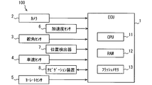
- FIG. 1 shows a schematic configuration of an in-vehicle system 100 including an ECU (Electronic Control Unit) 1 having a function as a sensor output correction device according to the present invention.
- ECU Electronic Control Unit
- the in-vehicle system 100 is mounted on a vehicle, and in addition to the ECU 1, as shown in FIG. 1, a camera 2, a steering angle sensor 3, a vehicle speed sensor 4, a yaw rate sensor 5, an acceleration sensor 6, a position detector 7, and A navigation device 8 is provided.
- the ECU 1 can communicate with each of the camera 2, the steering angle sensor 3, the vehicle speed sensor 4, the yaw rate sensor 5, the acceleration sensor 6, the position detector 7, and the navigation device 8 via a communication network built in the vehicle. It is connected to the.
- a vehicle on which the in-vehicle system 100 is mounted is hereinafter referred to as a system mounted vehicle.
- the camera 2 is a camera mounted on the vehicle so as to photograph a predetermined range outside the passenger compartment, and can be realized using an optical camera such as a CMOS camera or a CCD camera.
- the camera 2 is a so-called forward monitoring camera that captures a predetermined range in front of the system-equipped vehicle.
- the camera 2 may be installed in the vicinity of the windshield upper end, for example, in the vicinity of a room mirror. Image data taken by the camera 2 is sequentially provided to the ECU 1.
- the camera 2 is a front monitoring camera, but as another aspect, a camera (so-called rear monitoring camera) whose imaging range is behind the system-equipped vehicle may be used.
- the camera 2 corresponds to the in-vehicle camera described in the claims.
- the steering angle sensor 3 detects the steering angle of the system-equipped vehicle, and sequentially outputs a steering angle signal corresponding to the detected steering angle to the ECU 1.
- the vehicle speed sensor 4 is a sensor that detects the traveling speed of the vehicle, and sequentially outputs a vehicle speed signal corresponding to the detected traveling speed to the ECU 1.
- the yaw rate sensor 5 is a sensor that detects the rotational angular velocity (that is, the yaw rate) of the system-equipped vehicle around the vertical axis of the system-equipped vehicle, and sequentially outputs a signal indicating the detected yaw rate to the ECU 1.
- the vertical direction here is a direction orthogonal to both the front-rear direction and the vehicle width direction of the vehicle.
- the acceleration sensor 6 is a sensor that detects acceleration acting on the system-equipped vehicle, and sequentially outputs a signal indicating the detected acceleration to the ECU 1.
- the acceleration sensor 6 is a three-axis acceleration sensor that detects acceleration in each of three axial directions orthogonal to each other, such as a vehicle width direction, a vehicle front-rear direction, and a vertical direction.
- the acceleration sensor 6 may be an acceleration sensor that detects acceleration in two axial directions orthogonal to each other, or may be a single-axis sensor that detects acceleration acting in one direction.
- the position detector 7 detects the current position of the system-equipped vehicle based on a signal received from a positioning satellite by a receiver used for GNSS (Global Navigation Satellite System).
- the position detector 7 may perform dead reckoning that complements the detection result of the current position of the system-equipped vehicle using detection values of the yaw rate sensor 5 and the acceleration sensor 6.
- the detection result of the position detector 7, that is, the position information indicating the current position of the system-equipped vehicle is sequentially provided to the ECU 1 and the navigation device 8.
- the position information may be expressed by latitude and longitude, for example.
- the navigation device 8 provides the same function as a known navigation device. For example, based on the current position detected by the position detector 7 and road map data stored in a storage device (not shown), a map image around the system-equipped vehicle is displayed on the display, or the destination set by the user Or guide the travel route to. Further, the navigation device 8 can acquire information on the type of road on which the system-equipped vehicle is currently traveling, the number of lanes, and the road shape (curvature and gradient) from the current position of the system-equipped vehicle and road map data. It has a configuration.
- the ECU 1 may be connected to, for example, a shift position sensor that detects the gear shift position of the transmission, a brake pedal sensor that detects the amount of depression of the brake pedal, an accelerator pedal sensor that detects the amount of depression of the accelerator pedal, and the like.
- the ECU 1 is configured as a normal computer, and includes a CPU 11, a RAM 12 as a main storage device (so-called memory), a flash memory 13 as an auxiliary storage device (so-called storage), an I / O, and a bus line connecting them. Etc.
- the flash memory 13 stores a program for causing a normal computer to function as the ECU 1 according to the present embodiment.
- This program only needs to be stored in a non-transitory tangible storage medium provided in the ECU 1, and a specific storage medium may not be a flash memory. For example, it may be a ROM.
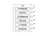
- the ECU 1 includes a vehicle information acquisition unit F1, a stop determination unit F2, a travel route information acquisition unit F3, a condition determination unit F4, and a zero point specification unit. F5 and a correction value determination unit F6 are provided.
- Each of the functional blocks may be realized by hardware using one or a plurality of IC chips. Further, the fact that the CPU executes the program corresponds to the execution of a method corresponding to the program.
- the RAM 12 provides a detection value storage unit M1, a zero point storage unit M2, and a correction value storage unit M3, which will be described later, using a part of the storage area, as shown in FIG.
- each of the detection value storage unit M1, the zero point storage unit M2, and the correction value storage unit M3 is configured to be realized by using a part of the storage area of the RAM 12, but as another mode, It may be realized by using a part of the storage area of the flash memory 13.
- the vehicle information acquisition unit F1 acquires the detection value ⁇ of the steering angle sensor 3, the detection value V of the vehicle speed sensor 4, the detection value Y of the yaw rate sensor 5, and the detection value A of the acceleration sensor.
- the vehicle information acquisition unit F1 corresponds to the detection value acquisition unit described in the claims.
- information indicating the behavior of these system-equipped vehicles is collectively referred to as vehicle information.
- vehicle information information indicating the behavior of these system-equipped vehicles is collectively referred to as vehicle information.
- vehicle information information indicating the behavior of these system-equipped vehicles is collectively referred to as vehicle information.
- vehicle information information indicating the behavior of these system-equipped vehicles is collectively referred to as vehicle information.
- the type of information included in the vehicle information is not limited to that described above.
- the position of the gear shift position detected by the shift position sensor, the depression amount of the brake pedal, the depression amount of the accelerator pedal, the connection state of the direction indicator lever, and the like may be included.
- the correction value used for the zero point correction is stored in the detection value storage unit M1 a certain number of times from the latest one.
- Zero point correction here refers to the sensor zero value that has deviated from the original correct zero due to aging, temperature characteristics, initial deviation of sensor output, etc. Is corrected so as to obtain a detection result in a state where is 0.
- the zero point for a sensor is a value output by the sensor in a situation where a physical state quantity that is detected by the sensor is not acting on the sensor. Usually, the zero point is designed to be zero.
- the correction value used for the zero point correction is used to remove an error component derived from the deviation of the zero point from the detected value of the sensor.
- the correction value is determined so as to correspond to the amount by which the zero point of the sensor is deviated from 0 (hereinafter, the amount of deviation).
- the stop determination unit F2 determines whether the system-equipped vehicle is stopped based on the vehicle information acquired by the vehicle information acquisition unit F1. As an example, here, when the traveling speed V of the system-equipped vehicle is equal to or less than a predetermined stop threshold (for example, 3 km / h) for determining that the system-equipped vehicle is stopped, the system-equipped vehicle is stopped. It is determined that
- the stop determination unit F2 stops the system-equipped vehicle based on the fact that the gear shift position is the parking position. You may determine that you are doing. Further, when the side brake is applied, it may be determined that the system-equipped vehicle is stopped.
- the stop determination part F2 changes from the state (it is set as a stop state) to the state (it is set as a drive state) from which the system mounting vehicle stops based on the determination result of whether it has stopped. It detects that it has changed and that it has changed from the running state to the stopped state.
- the travel path information acquisition unit F3 acquires travel path information that is information about a road (referred to as a travel path) on which the system-equipped vehicle is currently traveling. Examples of information included in the travel path information include curvature C, gradient, width, and the like. The travel path information only needs to include at least the curvature C, and may not include a gradient, a width, or the like.
- This travel path information acquisition part F3 is equivalent to the curvature acquisition part as described in a claim.
- the method by which the traveling road information acquisition unit F3 acquires the traveling road information may be designed as appropriate.
- the traveling road information acquisition unit F3 detects the lane markings provided on the road existing in front of the system-equipped vehicle by analyzing the image data provided from the camera 2, and the detection.
- the curvature of the lane marking thus obtained is acquired as the curvature C of the travel path.
- An image recognition technique for detecting a lane marking on a road from image data and a technique for estimating a curvature from a detected white line are known as disclosed in, for example, Japanese Patent Application Laid-Open No. 2013-196341. The description is omitted here.
- the travel route information acquisition unit F3 may acquire travel route information from the navigation device 8 when the ECU 1 and the navigation device 8 are connected as in the present embodiment.
- the curvature C of the traveling road may be estimated from a traveling locus generated by arranging the current positions sequentially detected by the position detector 7 in time series.
- the curvature C may be calculated
- the condition determination unit F4 determines whether or not a predetermined sampling condition is satisfied based on the vehicle information acquired by the vehicle information acquisition unit F1.
- the sampling condition is a condition that stipulates a situation in which a detection value used to estimate a value Yz corresponding to the current zero point of the correction target sensor (here, the yaw rate sensor 5) Yz is collected. .
- the sampling condition is a condition corresponding to a situation in which the correction target sensor can be regarded as outputting a value corresponding to the current zero point.
- the sampling condition is a condition that can be considered that the yaw rate is not acting on the system-equipped vehicle.
- the traveling speed V is equal to or higher than a predetermined vehicle speed threshold Vth
- the steering angle ⁇ is less than the predetermined steering angle threshold ⁇ th
- the curvature C is less than the predetermined curvature threshold Cth. 3 conditions (sub-conditions) are defined. Then, when all of these three sub-conditions are satisfied, it is determined that the sampling conditions are satisfied.
- the vehicle speed threshold value Vth used here is a threshold value that defines the lower limit of the traveling speed V that can be considered that the system-equipped vehicle is traveling.
- the vehicle speed threshold Vth may be the same value as the aforementioned stop threshold.
- the steering angle threshold value ⁇ th is a threshold value that defines an upper limit of the steering angle ⁇ that can be considered that the system-equipped vehicle is going straight ahead.
- the curvature threshold value Cth is a threshold value that defines an upper limit of the curvature C that can be considered (in other words, approximate) that the traveling road is a straight road (a straight road).
- the situation where the sampling condition is satisfied is that the system-equipped vehicle travels on a straight road in a state where the traveling speed is equal to or higher than the vehicle speed threshold Vth and the steering angle ⁇ is less than the steering angle threshold ⁇ th. It is a situation.
- the curvature threshold Cth corresponds to the approximate threshold described in the claims.
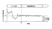
- FIG. 4 is a conceptual diagram showing the relationship between the detected value of the yaw rate sensor 5 and the travel path, where the horizontal axis of the graph represents the time axis, and the vertical axis represents the detected value of the yaw rate sensor 5.
- Time Ta represents a point in time when the system-equipped vehicle transitions from a state of traveling on a curve to a state of traveling on a straight road.
- Yz represents the zero point equivalent value of the current yaw rate sensor 5.
- the zero point equivalent value Yz corresponds to the amount of deviation of the zero point.
- the yaw rate acts on the system-equipped vehicle as shown in FIG. 4, so that the yaw rate sensor 5 has a current zero point equivalent value Yz and a yaw rate that acts on the system-equipped vehicle. A value with the corresponding value added is output.
- the yaw rate is unlikely to act on the system-equipped vehicle, so the detection value of the yaw rate sensor 5 can be expected to be a value close to the current zero point.
- the detection value output from the yaw rate sensor 5 in a situation where the sampling conditions described above are satisfied can be regarded as a value corresponding to the current zero point of the yaw rate sensor 5.
- the case where the detection value of the yaw rate sensor 5 can be expected to be a value close to the zero point is not only when traveling on a straight road. It can be expected that the detected value of the yaw rate sensor 5 while the vehicle is stopped is also outputting a value close to the current zero point.
- the zero point specifying unit F5 calculates the current zero point equivalent value Yz of the correction target sensor based on the detection values at a plurality of times of the correction target sensor (here, the yaw rate sensor 5) stored in the detection value storage unit M1. Identify. Specifically, N detection values collected while the sampling condition is satisfied are extracted from the detection value storage unit M1 as a population for specifying the current zero point equivalent value Yz of the yaw rate sensor 5. The average value of the population is set as the zero point equivalent value Yz of the correction target sensor. The zero point equivalent value Yz specified by the zero point specifying unit F5 is stored in the zero point storage unit M2.
- the zero point specifying unit F5 is not an average value of detection values constituting a population for calculating the correction value Q (referred to as a specific population), but a detection constituting the specific population.
- the median when the values are arranged in ascending order may be regarded as the zero point equivalent value Yz.
- the mode value in the specific population may be regarded as the zero point equivalent value Yz. That is, not only the average value but also various representative values used in statistics can be adopted as the zero point equivalent value Yz.
- the correction value determination unit F6 determines the correction value Q based on the zero point equivalent value Yz specified by the zero point specification unit F5.
- the zero point equivalent value Yz specified by the zero point specifying unit F5 is adopted as the correction value Q and stored in the correction value storage unit M3. Thereafter, the ECU 1 uses a value (correction detection value) Yq obtained by subtracting the correction value Q from the detection value Y for various control processes.
- the correction value Q is a value corresponding to the zero point equivalent value Yz of the yaw rate sensor 5, that is, the zero point deviation amount. Therefore, the correction detection value Yq obtained by subtracting the correction value Q from the detection value Y is a value that the yaw rate sensor 5 should originally detect, in other words, a value corresponding to the yaw rate actually acting on the system-equipped vehicle.
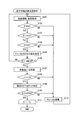
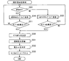
- a process for determining the correction value Q for the yaw rate sensor 5 based on the detection value of the yaw rate sensor 5 during traveling (the correction value determination process during traveling is performed) performed by the ECU 1. ).
- the flowchart shown in FIG. 5 may be started when the ignition power supply is turned on.
- this process is called again and executed. Thereby, while the ignition power is on, the running correction value determination process is sequentially executed.
- step S101 of FIG. 5 the vehicle information acquisition unit F1 acquires vehicle information, and the travel path information acquisition unit F3 acquires the curvature C of the travel path, and proceeds to step S102.
- step S102 the condition determination unit F4 determines whether or not the traveling speed V is equal to or higher than the vehicle speed threshold Vth. If the traveling speed V is greater than or equal to the vehicle speed threshold Vth, an affirmative determination is made in step S102 and the process proceeds to step S103. On the other hand, when the traveling speed V is less than the vehicle speed threshold value Vth, a negative determination is made in step S102, and the process proceeds to step S112.
- step S103 the condition determination unit F4 determines whether or not the steering angle ⁇ is less than the steering angle threshold ⁇ th. If the steering angle ⁇ is less than the steering angle threshold ⁇ th, an affirmative determination is made in step S103 and the process proceeds to step S104. On the other hand, when the steering angle ⁇ is equal to or larger than the steering angle threshold ⁇ th, a negative determination is made in step S103, and the process proceeds to step S112.
- step S104 the condition determination unit F4 determines whether the curvature C is less than a predetermined curvature threshold Cth. If the curvature C is less than the curvature threshold Cth, an affirmative determination is made in step S104 and the process proceeds to step S105. On the other hand, when the curvature C is equal to or greater than the curvature threshold Cth, a negative determination is made in step S104, and the process proceeds to step S112. Note that steps S102 to S104 correspond to a series of processes in which the condition determination unit F4 determines whether or not the sampling condition is satisfied. That is, the case where an affirmative determination is made in step S104 and the process proceeds to step S105 means that the sampling condition is satisfied.
- step S105 the vehicle information acquisition unit F1 stores the detection value of the yaw rate sensor 5 acquired in step S101 in the detection value storage unit M1, and proceeds to step S106.
- step S106 the zero point specifying unit F5 determines whether or not the number of detection values stored in the detection value storage unit M1 is N or more. If the number of detected values stored in the detected value storage unit M1 is N or more, an affirmative determination is made in step S106 and the process proceeds to step S107. On the other hand, if the number of detected values stored in the detected value storage unit M1 is less than N, a negative determination is made in step S106, the process returns to step S101, and collection of the detected values of the yaw rate sensor 5 is continued.
- the zero point specifying unit F5 uses the latest N detection values stored in the detection value storage unit M1 as the population for specifying the current zero point equivalent value Yz of the yaw rate sensor 5 (that is, specifying). And a fluctuation range ⁇ of the specific population is calculated.
- the fluctuation range ⁇ here determines whether or not the detection value of the yaw rate sensor 5 is stable while the detection value for specifying the current zero point equivalent value Yz of the yaw rate sensor 5 is collected. It is an index value for.
- the fluctuation range ⁇ is an absolute value of the difference between the minimum value and the maximum value of the detection values constituting the specific population, but is not limited thereto.
- the variance of the specific population and the standard deviation may be adopted as the fluctuation range ⁇ .
- the fluctuation range ⁇ corresponds to the degree of variation described in the claims.
- step S108 the zero point specifying unit F5 determines whether or not the fluctuation range ⁇ is equal to or less than a predetermined variation threshold ⁇ th.
- a predetermined variation threshold ⁇ th When the fluctuation range ⁇ is equal to or less than the variation threshold ⁇ th, an affirmative determination is made in step S108 and the process proceeds to step S109.
- the fluctuation width ⁇ is larger than the variation threshold ⁇ th, a negative determination is made in step S108, and the process proceeds to step S112.
- the variation threshold ⁇ th used here is such that the variation in the detection value of the yaw rate sensor 5 falls within a predetermined allowable range while the detection value for identifying the current zero point equivalent value Yz of the yaw rate sensor 5 is collected. It is a threshold value for determining whether or not it has been. If the behavior of the yaw rate sensor 5 is stabilized while collecting the detection value for specifying the current zero point equivalent value Yz of the yaw rate sensor 5, the fluctuation range ⁇ is equal to or less than the variation threshold ⁇ th. By including such a determination process in the travel correction value determination process, the current zero point equivalent value Yz can be specified with higher accuracy.
- step S109 the zero point specifying unit F5 calculates the average value of the specifying population. Then, the calculated average value is adopted as the current zero point equivalent value Yz of the yaw rate sensor 5, and the process proceeds to step S110.
- step S110 the correction value determination unit F6 uses the zero point equivalent value Yz stored in the correction value storage unit M3, which is used to determine the correction value Q that is currently employed, and the newly specified zero.
- a zero point displacement amount ⁇ Yz that is an absolute value of a difference between the point equivalent values Yz is calculated.
- the correction value determination unit F6 determines whether or not the calculated zero point displacement amount ⁇ Yz is equal to or greater than a predetermined displacement amount threshold value DYth. If the zero point displacement amount ⁇ Yz is greater than or equal to the displacement amount threshold value DYth, an affirmative determination is made in step S110 and the process proceeds to step S111. At that time, the zero point equivalent value Yz newly specified this time is stored in the zero point storage unit M2 as a zero point equivalent value used in determining the correction value Q. On the other hand, if the zero point displacement amount ⁇ Yz is less than the displacement amount threshold value DYth, a negative determination is made in step S110 and the process proceeds to step S112.
- the predetermined displacement threshold DYth corresponds to the upper limit of the error range described in the claims. Note that the lower limit of the error range described in the claims is zero.
- step S111 the zero point equivalent value Yz specified in step S109 is set as the correction value Q for the yaw rate sensor 5, and this flow is ended.
- step S112 the detection value for specifying the zero point equivalent value Yz stored in the detection value storage unit M1 is discarded, and the process returns to step S101.
- the ECU 1 when the detected value for N times can be acquired from the yaw rate sensor 5 while the sampling condition is satisfied (YES in step S106), the ECU 1 is based on the detected value for N times.
- the correction value Q can be updated to a value corresponding to the current zero point equivalent value Yz. That is, according to the above configuration, the correction value Q can be updated even during traveling. Note that the sampling condition is satisfied when the system-equipped vehicle travels on a straight road while the traveling speed is equal to or higher than the vehicle speed threshold Vth and the steering angle ⁇ is less than the steering angle threshold ⁇ th. Refers to the state of
- the correction value Q can be updated even while traveling. Therefore, the correction value Q used for the zero point correction deviates from the actual zero point deviation amount. Is suppressed.
- a plurality of yaw rate sensors are provided, and among the plurality of yaw rate sensors, the correction value of the sensor to be corrected is changed to another yaw rate.
- a configuration (second comparison configuration) determined using a detection value of a sensor (referred to as a comparison sensor) is also conceivable.
- the correction value calculated for the correction target sensor also includes an error. End up.
- the configuration of the present embodiment it is not necessary to provide a plurality of yaw rate sensors 5. Furthermore, according to the configuration of the present embodiment, the specific correction value Q for the yaw rate sensor 5 is determined only by the detection value of the yaw rate sensor 5 itself. Therefore, according to the configuration of the present embodiment, there is no possibility that an error in the detection value of the comparison sensor affects the correction value for the correction target sensor.
- the correction value of the yaw rate sensor 5 can be estimated as the yaw rate acting on the system-equipped vehicle such as a gyro sensor or a three-axis acceleration sensor. It is also possible to adopt a configuration in which a determination is made from the detection value of another sensor that detects a physical quantity. According to such an aspect, it is not necessary to provide a plurality of yaw rate sensors.
- this third configuration also has a difference with respect to the yaw rate sensor 5 if the detection value itself of the gyro sensor or the like corresponding to the comparison sensor or the triaxial acceleration sensor includes an error. There is a problem that an error is included in the determined correction value.
- the configuration of the present embodiment is superior to the third comparison configuration in that there is no possibility that the error included in the detection value of the comparison sensor affects the correction value. It can be said.
- the ECU 1 described in the first embodiment further performs a process of determining a correction value for the yaw rate sensor 5 based on a detection value of the yaw rate sensor 5 when stopped (referred to as a correction value determination process during stopping). May be. This is because the detected value during stoppage can also be expected to be a value corresponding to the current zero point.
- a correction value determination process during stopping
- step S201 the vehicle information acquisition unit F1 acquires vehicle information, and the traveling road information acquisition unit F3 acquires the curvature C of the traveling road, and proceeds to step S202.
- step S202 the condition determination unit F4 compares the current traveling speed V with the vehicle speed threshold Vth. If the traveling speed V is equal to or higher than the vehicle speed threshold Vth, an affirmative determination is made in step S202 and the process proceeds to step S203. On the other hand, when the traveling speed V is less than the vehicle speed threshold value Vth, a negative determination is made in step S202, and the process proceeds to step S209.
- step S203 the vehicle information acquisition unit F1 stores the detection value Y of the yaw rate sensor 5 acquired in step S201 in the detection value storage unit M1, and proceeds to step S204. It should be noted that the detection value stored in the stoppage correction value determination process and the detection value stored in the travel correction value determination process may be stored separately from each other in the detection value storage unit M1.
- step S204 the zero point specifying unit F5 determines whether or not the number of detected values collected while the vehicle is stored in the detected value storage unit M1 is N or more.
- the detected value stored in the detected value storage unit M1 is N or more
- an affirmative determination is made in step S204 and the process proceeds to step S205.
- the process returns to step S201, and collection of the detected values of the yaw rate sensor 5 is continued.
- step S205 the zero point specifying unit F5 reads the detection values for the latest N times among the detection values collected while the vehicle is stored in the detection value storage unit M1 as a specific population, and the specific population The fluctuation range ⁇ of is calculated.
- step S206 the process proceeds to step S206.
- step S206 the zero point specifying unit F5 compares the variation width ⁇ with the variation threshold ⁇ th, and when the variation width ⁇ is equal to or less than the variation threshold ⁇ th, an affirmative determination is made in step S206 and the processing proceeds to step S207. . On the other hand, if the fluctuation range ⁇ is larger than the variation threshold ⁇ th, a negative determination is made in step S206 and the process proceeds to step S209.
- step S207 the zero point specifying unit F5 calculates the average value of the specifying population. Then, the calculated average value is adopted as the current zero point equivalent value Yz of the yaw rate sensor 5, and the process proceeds to step S208.
- step S208 the correction value determination unit F6 sets the zero point equivalent value Yz specified in step S207 as the correction value Q for the yaw rate sensor 5. Then, the zero point equivalent value Yz newly specified this time is stored in the zero point storage unit M2 as the zero point equivalent value Yz used for determining the correction value Q, and this flow is ended.
- step S209 the detection values collected while the vehicle is stopped stored in the detection value storage unit M1 are discarded, and the process returns to step S201.
- the correction value Q of the yaw rate sensor 5 can be updated not only when the system-equipped vehicle is traveling but also when the vehicle is stopped. Further, when the system-equipped vehicle is stopped, the detection value of the yaw rate sensor 5 is more stable than the traveling state, and the possibility that the yaw rate is acting on the system-equipped vehicle is low. That is, the zero point equivalent value Yz determined from the detected value collected in the stopped state is more reliable than the zero point equivalent value Yz determined from the detected value collected in the traveling state. Therefore, according to the configuration of the present modification, it is possible to further suppress the correction value Q used for zero point correction from deviating from the actual zero point deviation amount.
- the determination process in step S110 in the traveling correction value determination process is omitted.
- the zero point equivalent value Yz used for determining the currently adopted correction value stored in the correction value storage unit M3 and the zero point equivalent value newly specified this time are used. Even if the difference in Yz is small, the correction value Q is updated to a value corresponding to the zero point equivalent value Yz newly specified this time.
- the zero point equivalent value Yz determined from the detected value collected in the stopped state is more reliable than the zero point equivalent value Yz determined from the detected value collected in the traveling state. Therefore, by omitting the determination process in step S110 in the travel correction value determination process, the ECU 1 can be updated to a more appropriate correction value Q, and the ECU 1 can use the correction value Q more appropriately. It becomes possible to execute the arithmetic processing.
- the ECU 1 according to the second embodiment as a functional block for realizing the above-described processing, includes a reliability evaluation unit F7 and a weight as shown in FIG. 7 in addition to various functional blocks provided in the ECU 1 according to the first embodiment.
- a determination unit F8 is provided.
- FIG. 7 illustration of various functional blocks described in the first embodiment is omitted.
- the reliability evaluation unit F7 evaluates the reliability of the zero point equivalent value Yz newly specified by the zero point specifying unit F5. Further, the weight determination unit F8 determines the weight ⁇ used when the zero point equivalent value Yz newly specified by the zero point specification unit F5 and the correction value Q currently employed are weighted and added.
- the weight ⁇ is a coefficient of the newly specified zero point equivalent value Yz as shown in the above formula 1. The larger the weight ⁇ (closer to 1), the more newly specified zero point equivalent value Yz. However, the ratio that contributes to the newly determined correction value Q increases. Details of the reliability evaluation unit F7 and the weight determination unit F8 will be described later.
- each of the reliability evaluation unit F7 and the weight determination unit F8 is implemented in software (that is, as a function provided by the CPU). It may be realized in hardware using an IC or the like.
- the correction value determination process may be started when the ignition power is turned on.
- this process is called again and executed. That is, this process is sequentially executed while the ignition power is on.
- step S301 the stop determination unit F2 determines whether or not the system-equipped vehicle is currently stopped. If the system-equipped vehicle is stopped, an affirmative determination is made in step S301 and the process proceeds to step S310. On the other hand, when the system-equipped vehicle is in a traveling state, a negative determination is made in step S301, and the process proceeds to step S320.
- This stopping sampling process is a process of collecting detection values for N times of the yaw rate sensor 5 in the stopped state.
- the specific processing content corresponds to a series of processing (including step S209) from step S201 to step S206 shown in FIG.
- step S310 for example, when the system-equipped vehicle shifts to the traveling state (NO in step S202), a negative determination is made in step S311 in FIG. 8 and the process returns to step S301.
- step S311 if the detection values for N times in which the fluctuation range ⁇ is less than the variation threshold ⁇ th have been successfully collected, an affirmative determination is made in step S311 and the process proceeds to step S330. .
- each part of the ECU 1, mainly the vehicle information acquisition unit F1, the stop determination unit F2, the condition determination unit F4, and the zero point specification unit F5 cooperate to execute the running sampling process.
- This during-running sampling process is a process of collecting the detection values for N times of the yaw rate sensor 5 in the running state of the system-equipped vehicle.
- the specific processing content corresponds to a series of processing (including step S112) from step S101 to step S108 shown in FIG.
- step S320 During the traveling sampling process in step S320, for example, when the system-equipped vehicle shifts to the stop state, a negative determination is made in step S321 in FIG. 8 and the process returns to step S301.
- step S320 As a result of the sampling processing during traveling in step S320, when the detection values for N times in which the fluctuation range ⁇ is less than the variation threshold ⁇ th have been successfully collected, an affirmative determination is made in step S321 and the process proceeds to step S330. .
- step S330 the zero point specifying unit F5 specifies the current zero point equivalent value Yz using the detection values collected by the stopping sampling process or the traveling sampling process as a specifying population, and the process proceeds to step S331.
- the zero point equivalent value Yz newly specified in step S330 is also referred to as a new specified value Yz for convenience.
- step S331 the reliability evaluation unit F7 evaluates the reliability for the new specific value Yz specified in step S330. Specifically, the reliability evaluation unit F7 determines that the new specific value Yz is the detected value during traveling when the new specific value Yz is a zero-point equivalent value that is specified using the detected value while stopped as a population. The reliability with respect to the new specific value Yz is evaluated higher than in the case of the zero point equivalent value specified as the population.
- the specific population collected in a situation where it can be expected that the vehicle is surely stopped Is more reliable for the new specific value Yz than when it is specified using the specific population collected when it is determined that the vehicle is stopped based only on the traveling speed V.
- the degree may be increased.
- the situation where the vehicle can be expected to stop reliably is, for example, immediately after the ignition power is turned on or when the shift position is in the parking position.
- the reliability may be further evaluated in stages. Specifically, the longer the distance (recognition distance) at which the lane marking existing in front of the system-equipped vehicle can be recognized by the image recognition processing, the higher the reliability with respect to the new specific value Yz is evaluated, and the recognition distance is shorter. The lower the reliability, the better.
- the high degree of curvature reliability corresponds to high reliability for the determination result (YES in step S104) that the system-equipped vehicle is traveling on a straight road.
- the fact that the determination result that the system-equipped vehicle is traveling on a straight road is highly reliable means that the detection value of the yaw rate sensor 5 collected during traveling truly corresponds to the current zero point. It means that there is a high possibility.
- the higher the possibility that the detected value of the yaw rate sensor 5 collected during traveling is a value corresponding to the zero point the higher the reliability with respect to the new specified value Yz specified based on the detected value. That is, it means that the new specific value Yz is a reliable value, so that the recognition distance of the lane marking when holding
- the reliability evaluation unit F7 may evaluate the reliability for the new specific value Yz as follows, for example, according to the situation when the detection values constituting the specific population are collected.
- the following is an example for explaining the hierarchical relationship of the reliability set for the new specific value Yz, and specific numerical values may be designed as appropriate.
- the reliability may be expressed not at a numerical value but at a level such as high, medium and low. In the following example, the larger the numerical value, the higher the reliability.
- the reliability is set to 100. If the detected value collected when it is determined that the vehicle is stopped based only on the traveling speed V, the reliability is set to 80.
- the new specific value Yz is specified using the detected value collected in the situation where the system-equipped vehicle is traveling and the recognition distance is equal to or greater than a certain distance, Is 60%. If the new specific value Yz is specified using the detected value collected in the situation where the system-equipped vehicle is traveling and the recognition distance is less than a certain distance, the reliability is The lower value is 40.
- the reliability evaluation method for the new specific value Yz is not limited to the example described above.
- the reliability of the new specific value Yz may be evaluated higher as the time interval from when the previous correction value is updated to when the new specific value Yz is specified this time is longer.
- step S332 the weight determination unit F8 determines the value of the weight ⁇ according to the reliability with respect to the new specific value Yz determined in step S330. That is, as the reliability for the new specific value Yz is higher, the weight ⁇ is set to a value closer to 1 that is the upper limit value.
- the process proceeds to step S333.
- step S333 the correction value determination unit F6 calculates a new correction value Q by substituting the weight ⁇ determined in step S332, the new specific value Yz, the correction value Qa currently employed, and Equation 1. This flow is finished.
- the correction value Q can be updated in accordance with the reliability of the newly specified zero point equivalent value Yz. Specifically, when the new specific value Yz is a value specified based on the detection value collected while the vehicle is stopped, the weight ⁇ for the new specific value Yz increases, so the new correction value Q is The new specific value Yz is reflected more strongly.
- the new specific value Yz is a value specified based on the detection value collected while the system-equipped vehicle is traveling.
- the weight ⁇ for the new specific value Yz increases. Therefore, the longer the recognition distance of the lane markings when collecting the detection values, the greater the ratio of the new specific value Yz that contributes to the new correction value Q.
- the weight ⁇ (T) is determined according to the elapsed time T after obtaining the specific value Yzstp at the time of stopping. Specifically, the weight ⁇ (T) increases as the elapsed time T from when the stationary specific value Yzstp is acquired is shorter (that is, close to 1), and the elapsed time since the stationary specific value Yzstp is acquired. It is designed to be smaller as time T is longer.
- the weight ⁇ (T) is designed to decrease from the initial value 1 in proportion to the elapsed time T, as indicated by a solid line in FIG.
- the weight ⁇ (T) may be reduced stepwise as shown by a broken line in FIG. 9, or may be reduced in a curve as shown by a one-dot chain line. It may be a thing.
- the initial value of the weight ⁇ (T) is 1 here, the initial value may be 0.9 or the like as another mode.
- the convergence value of the weight ⁇ (T) is 0, it may be 0.1 or the like.
- the weight ⁇ (T) may be defined as a function having the elapsed time T after obtaining the stop-time specific value Yzstp as a variable, and indicates a correspondence relationship between the elapsed time T and the weight ⁇ (T). It may be represented by a table or the like.
- the specific value of the weight ⁇ (T) may be updated by the correction value determination unit F6, for example.
- This correction value determination process may be started when the ignition power is turned on, as in the correction value determination process in the second embodiment. Further, when the running correction value determination process is normally completed while the ignition power is on, this process may be called again and executed.
- step S401 the stop determination unit F2 determines whether or not the system-equipped vehicle is currently stopped. If the system-equipped vehicle is stopped, an affirmative determination is made in step S401 and the process proceeds to S410. On the other hand, if the system-equipped vehicle is in a traveling state, a negative determination is made in S401 and the process proceeds to step S420.
- step S410 the stopping sampling process similar to that in step S310 is executed. That is, processing corresponding to a series of processing (including step S209) from step S201 to step S206 shown in FIG. 6 is performed.
- a negative determination is made in step S411 in FIG. 10 and the process returns to step S401.
- an affirmative determination is made in step S411 and the process proceeds to step S412. .
- step S412 the zero point specifying unit F5 specifies the current zero point equivalent value Yz using the detection values collected by the stopping sampling process as a specifying population, and the process proceeds to step S413.
- the zero point equivalent value Yz specified in step S412 corresponds to the stop time specific value Yzstp.
- the acquired stop-time specific value Yzstp is stored in the zero point storage unit M2 in association with the acquisition time, for example.
- step S420 a running sampling process similar to that in step S320 is executed. That is, processing corresponding to a series of processing (including step S112) from step S101 to step S108 shown in FIG. 5 is executed.
- processing corresponding to a series of processing including step S112 from step S101 to step S108 shown in FIG. 5 is executed.
- a negative determination is made in step S421 in FIG. 10 and the process returns to step S401.
- an affirmative determination is made in step S421 and the process proceeds to step S422. .
- step S422 the zero point specifying unit F5 specifies the current zero point equivalent value Yz using the detection values collected by the running sampling process as the specifying population, and proceeds to step S423.
- the zero point equivalent value Yz specified in step S422 corresponds to the traveling specific value Yzrun.
- the acquired travel time specific value Yzrun is stored in the zero point storage unit M2 separately from the stop time specific value Yzstp.
- step S423 the elapsed time T from the acquisition of the stop-time specific value Yzstp is acquired, the weight ⁇ (T) is updated to a value corresponding to the current elapsed time T, and the process proceeds to step S430.
- the elapsed time T may be measured by a timer or the like that measures the time after acquiring the stop-time specific value Yzstp, or the elapsed time by subtracting the acquisition time of the stop-time specific value Yzstp from the current time. It is good also as an aspect which calculates T.
- step S430 the correction value determining unit F6 substitutes the stopping specific value Yzstp, the traveling specific value Yzrun, and the weight ⁇ (T) set in step S413 or S423, which are stored in the zero point storage unit M2, into Equation 2.
- a new correction value Q is calculated, and this flow is finished.
- the weight ⁇ (T) used here is set so as to decrease as the traveling state of the system-equipped vehicle is maintained. Therefore, immediately after the stop-time specific value Yzstp can be acquired while the vehicle is stopped, the stop-time specific value Yzstp is more strongly reflected in the correction value Q. As the travel duration time increases, the ratio derived from the stop specific value Yzstp in the correction value Q decreases, and the ratio derived from the travel specific value Yzrun that is updated as needed during travel increases.
- the correction value Q in which the more specific stop-time specific value Yzstp is more strongly reflected. Further, in a time zone in which a change in the zero point due to a temperature change or the like is foreseen and the traveling duration is a certain value or more, the correction value Q more strongly reflecting the traveling specific value Yzrun updated during traveling. Will be available.
- the yaw rate sensor 5 is exemplified as the correction target sensor.
- the present invention is not limited to this.
- the steering angle sensor 3, the acceleration sensor 6, and a gyro sensor may be used as the correction target sensor.
- the sampling conditions during traveling may be designed as appropriate according to the state quantity detected by the sensor to be corrected.
- sampling conditions three sub-conditions are defined as sampling conditions.
- the present invention is not limited to this.
- two sub conditions for the curvature C and the sub condition for the traveling speed V may be used as the update conditions.
- conditions for parameters other than those described above may be included in the sampling conditions.
- the in-vehicle system 100 illustrated the aspect provided with the camera 2, the position detector 7, and the navigation apparatus 8 as a source device which provides the information regarding the curvature C of the road where the system-equipped vehicle is traveling. Not limited to this. That is, the in-vehicle system 100 does not have to include all three of these. Moreover, it is good also as an aspect which acquires the information regarding the curvature C of a travel path from source devices other than the above-mentioned.
Abstract
ゼロ点補正に用いられる補正値が、実際のゼロ点のずれ量から乖離してしまうことを抑制できるセンサ出力補正システムが提供される。ECUは、システム搭載車両が走行している道路である走行路の曲率を取得する走行路情報取得部と、ヨーレートセンサの検出値を取得する車両情報取得部を備える。ECUは、走行路情報取得部が取得している曲率に基づいて、システム搭載車両が直線路を走行しているか否かを判定し、システム搭載車両が直線路を走行している間に収集したヨーレートセンサの検出値に基づいて、ヨーレートセンサの現在のゼロ点のずれ量に相当する値(ゼロ点相当値)を特定する。そして、特定したゼロ点相当値を用いて、検出値から差し引くための補正値を決定する。
Description
本発明は、車両に搭載されているセンサの出力値を補正するセンサ出力補正装置に関する。
ヨーレートセンサや、舵角センサ、加速度センサ等といった種々のセンサが搭載されている車両がある。これらのセンサの出力値(以下、検出値ともいう)は、種々の制御処理に利用されるため、検出値に含まれる誤差は0であることが好ましい。
しかしながら、実際には、センサの経年劣化や温度特性、センサ出力の初期ズレなどにより、センサの出力値の中心値(つまりゼロ点)が、設計上の中心値(つまり0)からずれた状態となり、検出値に、ゼロ点のずれに起因する誤差が含まれるようになる。そのような問題に対し、センサのゼロ点のずれ量を推定し、その推定したずれ量に基づいてセンサの検出値を補正して用いる構成が種々提案されている。
例えば、特開2010-107244号公報には、車両のドアが開かれてから閉じられるまでの間の加速度センサの検出値に基づいて、加速度センサのゼロ点のずれ量に対応する補正値を算出し、加速度センサの検出値から補正値を差し引いた加速度センサの出力を用いる構成が開示されている。
特開2010-107244号公報に開示の方法では、車両のドアが開かれてから閉じられるまでの間のセンサの検出値が、補正値を算出するための基準として用いられる。しかしながら、イグニッション電源がオンとなっている間に車両のドアが開かれる状況とは、例えば出発時や駐車時等といった限定的な状況である。
そのため、特許文献1の方法では、補正値を算出するための基準として用いられるセンサ検出値を収集できる機会が少なく、それに伴って、補正値を算出及び更新する頻度も少なくなってしまう。
また、センサのゼロ点は、前述の通り、センサ周辺の温度に応じて変化するため、センサのゼロ点は、走行中においても動的に変化しうる。したがって、特開2010-107244号公報の構成では補正値を更新する機会が少ないため、ゼロ点補正に用いられる補正値が、実際のずれ量から乖離した値となりやすい。
本発明は、この事情に基づいて成されたものであり、その目的とするところは、ゼロ点補正に用いられる補正値が、実際のゼロ点のずれ量から乖離してしまうことを抑制できるセンサ出力補正装置を提供することにある。
その目的を達成するための本発明は、車両に搭載されてあって、車両に作用する所定の物理状態量を検出するセンサの検出値を逐次取得する検出値取得部(F1)と、車両が走行している道路である走行路の曲率を取得する曲率取得部(F3)と、曲率取得部が取得している曲率が、走行路を直線状の道路と近似することができる所定の近似閾値以下となっている場合に検出値取得部によって取得されたセンサの検出値に基づいて、センサの現在のゼロ点に相当する値であるゼロ点相当値を特定するゼロ点特定部(F5)と、ゼロ点特定部が特定したゼロ点相当値を用いて、センサの検出値から当該センサに生じているゼロ点のずれに由来する誤差を除去するための補正値を決定する補正値決定部(F6)と、を備えることを特徴とする。
以上の構成では、ゼロ点特定部は、センサの現在のゼロ点に相当するゼロ点相当値を、車両が直線状の道路を走行している間に取得した当該センサの検出値に基づいて特定する。そして、補正値決定部は、ゼロ点特定部が特定したゼロ点相当値を用いてゼロ点補正するための補正値を決定する。
以上の構成によれば、車両が走行中においても、現在のゼロ点のずれ量に対応する補正値を決定する事ができる。したがって、ゼロ点補正に用いられる補正値が、実際のゼロ点のずれ量から乖離してしまうことを抑制できる。
なお、特許請求の範囲に記載した括弧内の符号は、一つの態様として後述する実施形態に記載の具体的手段との対応関係を示すものであって、本発明の技術的範囲を限定するものではない。
以下、本発明の実施形態について図を用いて説明する。図1は、本発明に係るセンサ出力補正装置としての機能を備えるECU(Electronic Control Unit)1を備える車載システム100の概略的な構成を示す。
車載システム100は、車両に搭載されてあって、図1に示すようにECU1に加えて、カメラ2、舵角センサ3、車速センサ4、ヨーレートセンサ5、加速度センサ6、位置検出器7、及びナビゲーション装置8を備えている。ECU1は、カメラ2、舵角センサ3、車速センサ4、ヨーレートセンサ5、加速度センサ6、位置検出器7、及びナビゲーション装置8のそれぞれと、車両内に構築されている通信ネットワークを介して通信可能に接続されている。便宜上、この車載システム100が搭載されている車両を以降ではシステム搭載車両と称する。
カメラ2は、車室外の所定の範囲を撮影するように車両に搭載されているカメラであって、例えばCMOSカメラやCCDカメラ等の光学式カメラを用いて実現することができる。本実施形態においては一例としてカメラ2は、システム搭載車両の前方の所定範囲を撮影する、いわゆる前方監視カメラとする。カメラ2は、例えばルームミラー付近等の、ウインドシールド上端部近傍に設置されていればよい。カメラ2が撮影した画像データは、逐次ECU1に提供される。なお、本実施形態ではカメラ2を前方監視カメラとするが、他の態様としてシステム搭載車両の後方を撮影範囲とするカメラ(いわゆる後方監視カメラ)であってもよい。カメラ2が請求項に記載の車載カメラに相当する。
舵角センサ3は、システム搭載車両の舵角を検知し、その検出した舵角に応じた舵角信号をECU1に逐次出力する。車速センサ4は、車両の走行速度を検出するセンサであって、その検出した走行速度に応じた車速信号をECU1に逐次出力する。
ヨーレートセンサ5は、システム搭載車両の上下方向軸回りのシステム搭載車両の回転角速度(すなわちヨーレート)を検出するセンサであり、検出したヨーレートを示す信号をECU1に逐次出力する。ここでの上下方向とは、車両の前後方向及び車幅方向の何れとも直交する方向である。
加速度センサ6は、システム搭載車両に作用する加速度を検出するセンサであって、検出した加速度を示す信号をECU1に逐次出力する。なお、本実施形態において加速度センサ6は、車幅方向、車両前後方向、及び上下方向といった、互いに直交する3つの軸方向のそれぞれにおける加速度を検出する3軸加速度センサとする。もちろん、他の態様として加速度センサ6は、互いに直交する2つの軸方向の加速度を検出する加速度センサであってもよいし、1方向に作用する加速度を検出する1軸センサであってもよい。
位置検出器7は、GNSS(Global Navigation Satellite System)に用いられる受信機によって測位衛星から受信した信号をもとに、システム搭載車両の現在位置を検出する。位置検出器7は、ヨーレートセンサ5や加速度センサ6などの検出値を用いて、システム搭載車両の現在位置の検出結果を補完するデッドレコニング(Dead Reckoning)を行ってもよい。位置検出器7の検出結果、すなわちシステム搭載車両の現在位置を示す位置情報は、逐次ECU1及びナビゲーション装置8に提供される。位置情報は例えば緯度及び経度によって表されればよい。
ナビゲーション装置8は、周知のナビゲーション装置と同様の機能を提供する。例えば、位置検出器7が検出する現在位置と、図示しない記憶装置に格納されている道路地図データ等に基づき、システム搭載車両周辺の地図画像をディスプレイに表示したり、ユーザによって設定された目的地までの走行経路を案内したりする。また、ナビゲーション装置8は、システム搭載車両の現在位置と道路地図データとから、システム搭載車両が現在走行している道路の種別や、車線数、道路形状(曲率や勾配)についての情報を取得できる構成となっている。
なお、ECU1に接続するデバイス(センサを含む)は、上述したものに限らない。ECU1は、例えばトランスミッションのギアシフトポジションを検出するシフトポジションセンサや、ブレーキペダルの踏み込み量を検出するブレーキペダルセンサ、アクセルペダルの踏み込み量を検出するアクセルペダルセンサなどと接続されていても良い。
ECU1は、通常のコンピュータとして構成されており、CPU11や、主記憶装置(いわゆるメモリ)としてのRAM12、補助記憶装置(いわゆるストレージ)としてのフラッシュメモリ13、I/O、及びこれらを接続するバスラインなどを備えている。
フラッシュメモリ13には、通常のコンピュータを本実施形態に係るECU1として機能させるためのプログラムが格納されている。なお、このプログラムは、ECU1が備える非遷移的実体的記録媒体(non-transitory tangible storage media)に格納されていればよく、具体的な記憶媒体は、フラッシュメモリでなくともよい。例えばROMであってもよい。
ECU1は、上記プログラムを実行することで実現される機能ブロックとして図2に示すように、車両情報取得部F1、停車判定部F2、走行路情報取得部F3、条件判定部F4、ゼロ点特定部F5、及び補正値決定部F6を備える。なお、上記機能ブロックのそれぞれは、1つ又は複数のICチップなどを用いてハードウェア的に実現されても良い。また、CPUが上記プログラムを実行するということは、上記プログラムに対応する方法が実行されることに相当する。
RAM12は、その記憶領域の一部を用いて、図3に示すように後述する検出値記憶部M1、ゼロ点記憶部M2、補正値記憶部M3を提供する。なお、本実施形態において検出値記憶部M1、ゼロ点記憶部M2、及び補正値記憶部M3のそれぞれは、RAM12の記憶領域の一部を用いて実現する態様とするが、他の態様として、フラッシュメモリ13の記憶領域の一部を用いて実現してもよい。
車両情報取得部F1は、舵角センサ3の検出値θ、車速センサ4の検出値V、ヨーレートセンサ5の検出値Y、加速度センサの検出値Aを取得する。この車両情報取得部F1が請求項に記載の検出値取得部に相当する。以降では、これらのシステム搭載車両の挙動を示す情報をまとめて車両情報と称する。なお、車両情報に含まれる情報の種別は上述したものに限らない。シフトポジションセンサが検出するギアシフトポジションの位置や、ブレーキペダルの踏込量、アクセルペダルの踏み込み量、方向指示レバーの接続状態などが含まれていても良い。
また、車両情報取得部F1は、後述する条件判定部F4によってサンプリング条件が充足していると判定している場合には、車載システム100が備える種々のセンサのうち、0点補正に用いる補正値を決定(及び更新)する処理の対象とするセンサ(補正対象センサとする)から提供される検出値を、最新のものから一定回数分、検出値記憶部M1に保存する。検出値記憶部M1に保存する検出値の個数は、補正値を算出するために必要とする数(=N)以上であればよい。
ここでのゼロ点補正とは、経年劣化や温度特性、センサ出力の初期ズレなどに起因して、ゼロ点が本来の正しい0からずれてしまっているセンサの検出値を、当該センサのゼロ点が0となっている状態での検出結果となるように補正することである。或るセンサにとってのゼロ点とは、当該センサが検出対象とする物理状態量が当該センサに作用していない状況において、当該センサが出力する値である。通常、ゼロ点は0となるように設計される。
ゼロ点補正に用いられる補正値は、センサの検出値からゼロ点のずれに由来する誤差成分を除去するために用いられる。補正値は、センサのゼロ点が0からずれている量(以降、ずれ量)に対応するように決定される。
以降では一例として、ヨーレートセンサ5を補正対象センサとして、本実施形態の作動を説明する。
停車判定部F2は、車両情報取得部F1が取得した車両情報に基づいて、システム搭載車両が停車しているか否かを判定する。一例としてここでは、システム搭載車両の走行速度Vが、システム搭載車両が停車していると判定するための所定の停車閾値(例えば3km/h)以下となっている場合に、システム搭載車両が停車していると判定する。
なお、他の態様として停車判定部F2は、車両情報取得部F1が車両情報としてギアシフトポジションの位置を取得する場合には、ギアシフトポジションが駐車位置になっていることに基づいてシステム搭載車両が停車していると判定してもよい。また、サイドブレーキが引かれている場合に、システム搭載車両が停車していると判定してもよい。
また、停車判定部F2は、停車しているか否かの判定結果に基づいて、システム搭載車両が停車している状態(停車状態とする)から走行している状態(走行状態とする)へと遷移したこと、及び、走行状態から停車状態へと遷移したことを検出する。
走行路情報取得部F3は、システム搭載車両が現在走行している道路(走行路とする)についての情報である走行路情報を取得する。走行路情報に含まれる情報としては、例えば曲率Cや、勾配、幅員等が該当する。なお、走行路情報には、少なくとも曲率Cが含まれていればよく、勾配や幅員などは含まれていなくとも良い。曲率Cは、曲率半径R[m]の逆数によって表される(すなわち、C=1/R)。この走行路情報取得部F3が請求項に記載の曲率取得部に相当する。
走行路情報取得部F3が走行路情報を取得する方法は、適宜設計されれば良い。本実施形態では一例として、走行路情報取得部F3は、カメラ2から提供される画像データを解析することで、システム搭載車両前方に存在する道路に設けられている区画線を検出し、その検出した区画線の曲率を、走行路の曲率Cとして取得する。画像データから道路上の区画線を検出するための画像認識技術や、検出した白線から曲率を推定する技術については、例えば特開2013-196341号公報に開示されているように公知であるため、ここではその説明は省略する。
また、走行路情報取得部F3は、本実施形態のようにECU1とナビゲーション装置8とが接続している場合には、ナビゲーション装置8から走行路情報を取得してもよい。さらに、位置検出器7が逐次検出する現在位置を時系列順に並べて生成される走行軌跡から、走行路の曲率Cを推定してもよい。また、これらの方法を相補的に利用することで曲率Cを求めてもよいし、上記以外の方法で曲率Cを取得してもよい。
条件判定部F4は、車両情報取得部F1が取得している車両情報に基づき、所定のサンプリング条件が充足されているか否かを判定する。サンプリング条件は、補正対象センサ(ここではヨーレートセンサ5)の現在のゼロ点に相当する値(ゼロ点相当値とする)Yzを推定するために用いる検出値を収集する状況を規定する条件である。言い換えれば、サンプリング条件は、補正対象センサが、現在のゼロ点に相当する値を出力していると見なすことができる状況に対応する条件である。
本実施形態ではヨーレートセンサ5が補正対象センサであるため、サンプリング条件は、システム搭載車両にヨーレートが作用していないと見なすことができる条件とする。具体的には、サンプリング条件として、走行速度Vが所定の車速閾値Vth以上であること、舵角θが所定の舵角閾値θth未満であること、曲率Cが所定の曲率閾値Cth未満となっていること、の3つの条件(サブ条件とする)を定義する。そして、これらの3つのサブ条件の全てが充足されている場合に、サンプリング条件が充足されていると判定する。
なお、ここで用いる車速閾値Vthは、システム搭載車両が走行していると見なすことができる走行速度Vの下限を規定する閾値である。車速閾値Vthは、前述の停車閾値と同じ値となっていても良い。また、舵角閾値θthは、システム搭載車両が直進しようとしていると見なすことができる舵角θの上限を規定する閾値である。曲率閾値Cthは、走行路が直線状の道路(直線路とする)であると見なす(言い換えれば、近似する)ことができる曲率Cの上限を規定する閾値である。
したがって、上記サンプリング条件が充足される状況とは、システム搭載車両が、走行速度が車速閾値Vth以上、かつ、舵角θが舵角閾値θth未満となっている状態で、直線路を走行している状況である。なお、曲率閾値Cthが請求項に記載の近似閾値に相当する。
図4は、ヨーレートセンサ5の検出値と、走行路との関係を示した概念図であり、グラフの横軸は時間軸を、縦軸はヨーレートセンサ5の検出値を表している。時刻Taは、システム搭載車両がカーブを走行している状態から直線路を走行している状態へと移行した時点を表している。また、Yzは、現在のヨーレートセンサ5のゼロ点相当値を表している。ゼロ点相当値Yzは、ゼロ点のずれ量に相当する。
システム搭載車両がカーブを走行している場合には、図4に示すようにシステム搭載車両にヨーレートが作用するため、ヨーレートセンサ5現在のゼロ点相当値Yzに、システム搭載車両に作用するヨーレートに応じた値が加わった値が出力される。一方、直線路走行中においては、システム搭載車両にヨーレートが作用しにくいため、ヨーレートセンサ5の検出値は、現在のゼロ点に近い値となることが期待できる。
つまり、上述したサンプリング条件が充足されている状況においてヨーレートセンサ5から出力される検出値は、ヨーレートセンサ5の現在のゼロ点に相当する値と見なすことができる。なお、ヨーレートセンサ5の検出値がゼロ点に近い値となることが期待できる場合とは、直線路走行時だけではない。停車中におけるヨーレートセンサ5の検出値もまた、現在のゼロ点に近い値を出力していると期待できる。
ゼロ点特定部F5は、検出値記憶部M1に保存されている、補正対象センサ(ここではヨーレートセンサ5)の複数時点における検出値に基づいて、補正対象センサの現在のゼロ点相当値Yzを特定する。具体的には、サンプリング条件が充足されている間に収集されたN個の検出値を、ヨーレートセンサ5の現在のゼロ点相当値Yzを特定するための母集団として検出値記憶部M1から抽出し、当該母集団の平均値を、補正対象センサのゼロ点相当値Yzとする。ゼロ点特定部F5が特定したゼロ点相当値Yzは、ゼロ点記憶部M2に保存される。
なお、他の態様としてゼロ点特定部F5は、補正値Qを算出するための母集団(特定用母集団とする)を構成する検出値の平均値でなく、特定用母集団を構成する検出値を小さい順に並べた時の中央値を、ゼロ点相当値Yzと見なしてもよい。また、特定用母集団における最頻値をゼロ点相当値Yzと見なしてもよい。つまり、平均値に限らず、統計学において用いられている種々の代表値をゼロ点相当値Yzとして採用することができる。
補正値決定部F6は、ゼロ点特定部F5が特定したゼロ点相当値Yzに基づいて、補正値Qを決定する。本実施形態においては、ゼロ点特定部F5が特定したゼロ点相当値Yzを補正値Qとして採用し、補正値記憶部M3に保存する。その後、ECU1は、検出値Yから補正値Qを差し引いた値(補正検出値)Yqを、種々の制御処理に用いる。
補正値Qは、上述の通り、ヨーレートセンサ5のゼロ点相当値Yz、つまり、ゼロ点のずれ量に対応する値となっている。そのため、検出値Yから補正値Qを差し引いた補正検出値Yqは、ヨーレートセンサ5が本来検出するべき値、言い換えればシステム搭載車両に実際に作用しているヨーレートに相当する値となる。
次に、図5に示すフローチャートを用いて、ECU1が実施する、走行中におけるヨーレートセンサ5の検出値に基づいて、ヨーレートセンサ5に対する補正値Qを決定する処理(走行中補正値決定処理とする)について説明する。この図5に示すフローチャートは、イグニッション電源がオンとなった場合に開始されればよい。また、イグニッション電源がオンとなっている間において、走行中補正値決定処理が正常に終了した場合には、再び本処理が呼び出されて実行される。これにより、イグニッション電源がオンとなっている間は、この走行中補正値決定処理が逐次実行される。
まず、図5のステップS101では車両情報取得部F1が車両情報を取得するとともに、走行路情報取得部F3が走行路の曲率Cを取得してステップS102に移る。ステップS102では条件判定部F4が、走行速度Vが車速閾値Vth以上となっているか否かを判定する。走行速度Vが車速閾値Vth以上となっている場合には、ステップS102が肯定判定されてステップS103に移る。一方、走行速度Vが車速閾値Vth未満となっている場合には、ステップS102が否定判定されてステップS112に移る。
ステップS103では条件判定部F4が、舵角θが舵角閾値θth未満となっているか否かを判定する。舵角θが舵角閾値θth未満となっている場合には、ステップS103が肯定判定されてステップS104に移る。一方、舵角θが舵角閾値θth以上となっている場合には、ステップS103が否定判定されてステップS112に移る。
ステップS104では条件判定部F4が、曲率Cが所定の曲率閾値Cth未満となっているか否かを判定する。曲率Cが曲率閾値Cth未満となっている場合には、ステップS104が肯定判定されてステップS105に移る。一方、曲率Cが曲率閾値Cth以上となっている場合には、ステップS104が否定判定されてステップS112に移る。なお、ステップS102~S104は、条件判定部F4が、サンプリング条件が充足されているか否かを判定する一連の処理に相当する。すなわち、ステップS104で肯定判定されてステップS105に移る場合とはサンプリング条件が充足している状況であることを意味している。
ステップS105では車両情報取得部F1が、ステップS101で取得したヨーレートセンサ5の検出値を検出値記憶部M1に保存してステップS106に移る。ステップS106ではゼロ点特定部F5が、検出値記憶部M1に保存されている検出値の数がN個以上となっているか否かを判定する。検出値記憶部M1に保存されている検出値の数がN個以上となっている場合には、ステップS106が肯定判定されてステップS107に移る。一方、検出値記憶部M1に保存されている検出値の数がN個未満である場合には、ステップS106が否定判定されてステップS101に戻り、ヨーレートセンサ5の検出値の収集を継続する。
ステップS107ではゼロ点特定部F5が、検出値記憶部M1に保存されている、最新N回分の検出値を、ヨーレートセンサ5の現在のゼロ点相当値Yzを特定するための母集団(つまり特定用母集団)として読み出し、その特定用母集団の変動幅σを算出する。ここでの変動幅σは、ヨーレートセンサ5の現在のゼロ点相当値Yzを特定するための検出値を収集している間において、ヨーレートセンサ5の検出値が安定していたか否かを判定するための指標値である。
ここでは一例として変動幅σは、特定用母集団を構成する検出値の最小値と最大値の差の絶対値とするが、これに限らない。他の態様として、特定用母集団の分散や、標準偏差を変動幅σとして採用しても良い。変動幅σが請求項に記載のばらつき度合いに相当する。このステップS107での処理が完了するとステップS108に移る。
ステップS108ではゼロ点特定部F5が、変動幅σが所定のばらつき閾値σth以下となっているか否かを判定する。変動幅σがばらつき閾値σth以下となっている場合には、ステップS108が肯定判定されてステップS109に移る。一方、変動幅σがばらつき閾値σthよりも大きい場合には、ステップS108が否定判定されてステップS112に移る。
ここで用いるばらつき閾値σthは、ヨーレートセンサ5の現在のゼロ点相当値Yzを特定するための検出値を収集している間において、ヨーレートセンサ5の検出値のばらつきが所定の許容範囲内に収まっていたか否かを判定するための閾値である。ヨーレートセンサ5の現在のゼロ点相当値Yzを特定するための検出値を収集している間において、ヨーレートセンサ5の挙動が安定した場合には、変動幅σはばらつき閾値σth以下となる。このような判定処理を走行中補正値決定処理に含ませることで、現在のゼロ点相当値Yzをより精度良く特定することができる。
ステップS109ではゼロ点特定部F5が、特定用母集団の平均値を算出する。そして、その算出された平均値を、ヨーレートセンサ5の現在のゼロ点相当値Yzとして採用し、ステップS110に移る。
ステップS110では補正値決定部F6が、現在採用されている補正値Qを決定する上で用いられた、補正値記憶部M3に保存されているゼロ点相当値Yzと、今回新たに特定したゼロ点相当値Yzの差の絶対値であるゼロ点変位量ΔYzを算出する。
そして補正値決定部F6は、算出したゼロ点変位量ΔYzが、所定の変位量閾値DYth以上となっているか否かを判定する。ゼロ点変位量ΔYzが変位量閾値DYth以上となっている場合には、ステップS110が肯定判定されてステップS111に移る。その際、今回新たに特定したゼロ点相当値Yzを、補正値Qを決定する上で用いられるゼロ点相当値としてゼロ点記憶部M2に保存する。一方、ゼロ点変位量ΔYzが変位量閾値DYth未満となっている場合には、ステップS110が否定判定されてステップS112に移る。所定の変位量閾値DYthが請求項に記載の誤差範囲の上限に相当する。なお、請求項に記載の誤差範囲の下限は0となる。
ステップS111では、ステップS109で特定されたゼロ点相当値Yzをヨーレートセンサ5に対する補正値Qに設定して本フローを終了する。また、ステップS112では、検出値記憶部M1に蓄積されている、ゼロ点相当値Yzを特定するための検出値を破棄してステップS101に戻る。
<第1実施形態のまとめ>
以上の構成によれば、ECU1は、サンプリング条件が充足されている間にヨーレートセンサ5からN回分の検出値を取得できた場合には(ステップS106 YES)、そのN回分の検出値に基づいて、補正値Qを、現在のゼロ点相当値Yzに対応する値に更新することができる。つまり、以上の構成によれば、走行中においても補正値Qを更新することができる。なお、サンプリング条件が充足されている状態とは、システム搭載車両が直線路を、走行速度が車速閾値Vth以上であって、かつ、舵角θが舵角閾値θth未満となっている状態で走行している状態を指す。
以上の構成によれば、ECU1は、サンプリング条件が充足されている間にヨーレートセンサ5からN回分の検出値を取得できた場合には(ステップS106 YES)、そのN回分の検出値に基づいて、補正値Qを、現在のゼロ点相当値Yzに対応する値に更新することができる。つまり、以上の構成によれば、走行中においても補正値Qを更新することができる。なお、サンプリング条件が充足されている状態とは、システム搭載車両が直線路を、走行速度が車速閾値Vth以上であって、かつ、舵角θが舵角閾値θth未満となっている状態で走行している状態を指す。
ところで、補正値を算出する別の構成(第1比較構成とする)としては、停車中に収集した検出値に基づいて補正値を算出及び更新する態様も考えられる。しかしながら、ゼロ点のずれ量は、ヨーレートセンサ5の周囲の温度に応じて変化する。そのため、停車中の検出値に基づいて補正値を更新したとしても、走行状態が継続している時間(走行継続時間)が長引くにつれて、停車中に算出された補正値が、実際のずれ量から乖離した値となってしまう場合がある。
このような課題に対し、以上の構成によれば、走行中においても補正値Qを更新することができるため、ゼロ点補正に用いられる補正値Qが、実際のゼロ点のずれ量から乖離してしまうことを抑制される。
また、ヨーレートセンサに対する補正値を走行中に更新するための別の解決策としては、ヨーレートセンサを複数備えさせ、それら複数のヨーレートセンサのうち、補正対象とするセンサの補正値を、別のヨーレートセンサ(比較用センサとする)の検出値を用いて決定する構成(第2比較構成)も考えられる。
しかし、そのような方法においては、ヨーレートセンサ5を複数備える必要があり、コストアップにつながってしまう。また、比較用センサの検出値自体に、ゼロ点のドリフト等に起因する誤差が含まれている場合には、補正対象センサに対して算出される補正値にも誤差が含まれることになってしまう。
そのような課題に対し、本実施形態の構成によれば、ヨーレートセンサ5を複数備える必要はない。さらに、本実施形態の構成によれば、ヨーレートセンサ5に対する具体的な補正値Qは、そのヨーレートセンサ5自身の検出値のみによって定まる。したがって、本実施形態の構成によれば、比較用センサの検出値の誤差が、補正対象センサに対する補正値に影響を及ぼすといった問題が生じる恐れがない。
また、第2比較構成に類似する比較構成(第3比較構成とする)としては、ヨーレートセンサ5の補正値を、ジャイロセンサ等や3軸加速度センサといった、システム搭載車両に作用するヨーレートを推定可能な物理状態量を検出する別のセンサの検出値から決定する構成も考えられる。そのような態様によれば、ヨーレートセンサを複数備えさせる必要ない。しかし、この第3構成も第2比較構成と同様に、比較用センサに相当するジャイロセンサ等や3軸加速度センサの検出値自体に誤差が含まれている場合には、ヨーレートセンサ5に対して決定される補正値にも誤差が含まれてしまうといった問題が生じる。
したがって、本実施形態の構成は、第3比較構成に対しても、比較用センサの検出値に含まれている誤差が補正値に影響を及ぼすといった問題が生じる恐れがないという観点において優れていると言える。
以上、本発明の実施形態を説明したが、本発明は上述の実施形態に限定されるものではなく、以降で述べる種々の変形例や実施形態も、本発明の技術的範囲に含まれ、さらに、下記以外にも要旨を逸脱しない範囲内で種々変更して実施することができる。
[第1実施形態の変形例]
前述の第1実施形態で述べたECU1は、さらに、停車中のヨーレートセンサ5の検出値に基づいて、ヨーレートセンサ5に対する補正値を決定する処理(停車中補正値決定処理とする)を実施してもよい。停車中の検出値もまた、現在のゼロ点に相当する値となっていることが期待できるためである。以下、この停車中補正値決定処理について、図6に示すフローチャートを用いて説明する。
前述の第1実施形態で述べたECU1は、さらに、停車中のヨーレートセンサ5の検出値に基づいて、ヨーレートセンサ5に対する補正値を決定する処理(停車中補正値決定処理とする)を実施してもよい。停車中の検出値もまた、現在のゼロ点に相当する値となっていることが期待できるためである。以下、この停車中補正値決定処理について、図6に示すフローチャートを用いて説明する。
この図6に示すフローチャートは、例えばイグニッション電源がオンとなって、ECU1が起動した場合、及び、停車判定部F2によってシステム搭載車両が走行状態から停車状態へと遷移したことを検出された場合に開始されればよい。なお、この停車中補正値決定処理と、前述の走行中補正値決定処理とは、並列的に(互いに独立して)実施されれば良い。
まず、ステップS201では、車両情報取得部F1が車両情報を取得するとともに、走行路情報取得部F3が走行路の曲率Cを取得してステップS202に移る。ステップS202では条件判定部F4が、現在の走行速度Vと車速閾値Vthを比較し、走行速度Vが車速閾値Vth以上となっている場合には、ステップS202が肯定判定されてステップS203に移る。一方、走行速度Vが車速閾値Vth未満となっている場合には、ステップS202が否定判定されてステップS209に移る。
ステップS203では車両情報取得部F1が、ステップS201で取得したヨーレートセンサ5の検出値Yを検出値記憶部M1に保存してステップS204に移る。なお、この停車中補正値決定処理で保存される検出値と、走行中補正値決定処理で保存される検出値とは、検出値記憶部M1において互いに区別して保存されればよい。
ステップS204ではゼロ点特定部F5が、検出値記憶部M1に保存されている、停車中に収集した検出値の数がN個以上となっているか否かを判定する。検出値記憶部M1に保存されている検出値がN個以上となっている場合には、ステップS204が肯定判定されてステップS205に移る。一方、検出値記憶部M1に保存されている検出値の数がN個未満である場合には、ステップS204が否定判定されてステップS201に戻り、ヨーレートセンサ5の検出値の収集を継続する。
ステップS205ではゼロ点特定部F5が、検出値記憶部M1に保存されている、停車中に収集した検出値のうち、最新N回分の検出値を特定用母集団として読み出し、その特定用母集団の変動幅σを算出する。このステップS205での処理が完了するとステップS206に移る。
ステップS206ではゼロ点特定部F5が、変動幅σとばらつき閾値σthとを比較して、変動幅σがばらつき閾値σth以下となっている場合には、ステップS206が肯定判定されてステップS207に移る。一方、変動幅σがばらつき閾値σthよりも大きい場合には、ステップS206が否定判定されてステップS209に移る。
ステップS207ではゼロ点特定部F5が、特定用母集団の平均値を算出する。そして、その算出された平均値を、ヨーレートセンサ5の現在のゼロ点相当値Yzとして採用し、ステップS208に移る。
ステップS208では補正値決定部F6が、ステップS207で特定されたゼロ点相当値Yzをヨーレートセンサ5に対する補正値Qに設定する。そして、今回新たに特定したゼロ点相当値Yzを、補正値Qを決定する上で用いられるゼロ点相当値Yzとしてゼロ点記憶部M2に保存し、本フローを終了する。ステップS209では、検出値記憶部M1に蓄積されている、停車中において収集した検出値を破棄してステップS201に戻る。
以上の構成によれば、システム搭載車両の走行中だけでなく、停車中においてもヨーレートセンサ5の補正値Qを更新することができる。また、システム搭載車両の停車状態においては、走行状態よりも、ヨーレートセンサ5の検出値が安定してあって、かつ、システム搭載車両にヨーレートが作用している可能性が低い。すなわち、停車状態において収集した検出値から定まるゼロ点相当値Yzは、走行状態において収集した検出値から定まるゼロ点相当値Yzよりも信頼性が高い。したがって、本変形例の構成によれば、ゼロ点補正に用いられる補正値Qが、実際のゼロ点のずれ量から乖離してしまうことをより一層抑制できる。
また、本変形例の停車中補正値決定処理では、走行中補正値決定処理におけるステップS110での判定処理を省略する。このような態様によれば、補正値記憶部M3に保存されている、現在採用されている補正値を決定するために用いられたゼロ点相当値Yzと、今回新たに特定したゼロ点相当値Yzの差が小さい場合であっても、補正値Qを今回新たに特定されたゼロ点相当値Yzに対応する値に更新させることになる。
前述の通り、停車状態において収集した検出値から定まるゼロ点相当値Yzは、走行状態において収集した検出値から定まるゼロ点相当値Yzよりも信頼性が高い。したがって、走行中補正値決定処理におけるステップS110での判定処理を省略することで、ECU1は、より適切な補正値Qに更新することができ、ECU1はより適切な補正値Qを利用して種々の演算処理を実行できるようになる。
[第2実施形態]
次に、本発明の第2実施形態について図を用いて説明する。なお、以降において前述の第1実施形態(及びその変形例)の構成の部材と同一の機能を有する部材については、同一の符号を付し、その説明を省略する。また、構成の一部のみに言及している場合、他の部分については先に説明した第1実施形態(及びその変形例)を適用することができる。
次に、本発明の第2実施形態について図を用いて説明する。なお、以降において前述の第1実施形態(及びその変形例)の構成の部材と同一の機能を有する部材については、同一の符号を付し、その説明を省略する。また、構成の一部のみに言及している場合、他の部分については先に説明した第1実施形態(及びその変形例)を適用することができる。
第1実施形態及びその変形例と、第2実施形態との主たる相違点は、本実施形態においては、ゼロ点特定部F5が新たに特定したゼロ点相当値Yzと、現在採用している補正値とを、所定の重みα(0≦α≦1)を用いて重み付け加算することで、新たな補正値Qを決定する点にある。具体的には、現在採用している補正値をQaとすると、新たな補正値Qは、下記式で求める態様とする。
(式1) Q=Qa×(1-α)+Yz×α
(式1) Q=Qa×(1-α)+Yz×α
第2実施形態におけるECU1は、上述した処理を実現するための機能ブロックとして、第1実施形態のECU1が備える種々の機能ブロックに加えて、図7に示すように、信頼度評価部F7と重み決定部F8を備える。なお、図7においては、第1実施形態で説明した種々の機能ブロックの図示を省略している。
この信頼度評価部F7は、ゼロ点特定部F5が新たに特定したゼロ点相当値Yzに対する信頼度を評価する。また、重み決定部F8は、ゼロ点特定部F5が新たに特定したゼロ点相当値Yzと、現在採用している補正値Qとを重み付け加算する際に用いる重みαを決定する。重みαは、上記式1に示すように、新たに特定されたゼロ点相当値Yzの係数であって、重みαが大きいほど(1に近い程)、新たに特定されたゼロ点相当値Yzが、新たに決定される補正値Qに寄与する割合が大きくなる。この信頼度評価部F7及び重み決定部F8の詳細については、別途後述する。
なお、本実施形態において信頼度評価部F7及び重み決定部F8のそれぞれは、ソフトウェア的に(すなわちCPUが提供する機能として)実現される態様とするが、他の態様として、1つ乃至複数のICなどを用いてハードウェア的に実現されても良い。
次に、この第2実施形態のECU1が実施する、ヨーレートセンサ5に対する補正値Qを決定する処理(補正値決定処理とする)について、図8を用いて説明する。なお、この補正値決定処理は、イグニッション電源がオンとなった場合に開始されればよい。また、イグニッション電源がオンとなっている間において、走行中補正値決定処理が正常に終了した場合には、再び本処理が呼び出されて実行される。つまり、イグニッション電源がオンとなっている間、本処理は逐次実行される。
まず、ステップS301では停車判定部F2が、現在システム搭載車両が停車しているか否かを判定する。システム搭載車両が停車状態となっている場合には、ステップS301が肯定判定されてステップS310に移る。一方、システム搭載車両が走行状態となっている場合にはステップS301が否定判定されてステップS320に移る。
ステップS310ではECU1の各部、主として、車両情報取得部F1、停車判定部F2、条件判定部F4、及びゼロ点特定部F5が協働して、停車中サンプリング処理を実行する。この停車中サンプリング処理は、停車状態におけるヨーレートセンサ5のN回分の検出値を収集する処理である。その具体的な処理内容は、図6に示すステップS201からステップS206までの一連の処理(ステップS209を含む)に相当する。
このステップS310の停車中サンプリング処理の間において、例えばシステム搭載車両が走行状態へ移行した場合(ステップS202 NO)には、図8のステップS311が否定判定されてステップS301に戻る。一方、ステップS310の停車中サンプリング処理の結果、変動幅σがばらつき閾値σth未満に収まっているN回分の検出値を収集することに成功した場合にはステップS311が肯定判定されてステップS330に移る。
ステップS320ではECU1の各部、主として、車両情報取得部F1、停車判定部F2、条件判定部F4、及びゼロ点特定部F5が協働して、走行中サンプリング処理を実行する。この走行中サンプリング処理は、システム搭載車両の走行状態におけるヨーレートセンサ5のN回分の検出値を収集する処理である。その具体的な処理内容は、図5に示すステップS101からステップS108までの一連の処理(ステップS112を含む)に相当する。
このステップS320の走行中サンプリング処理の間において、例えばシステム搭載車両が停車状態へ移行した場合には、図8のステップS321が否定判定されてステップS301に戻る。一方、ステップS320の走行中サンプリング処理の結果、変動幅σがばらつき閾値σth未満に収まっているN回分の検出値を収集することに成功した場合にはステップS321が肯定判定されてステップS330に移る。
ステップS330ではゼロ点特定部F5が、停車中サンプリング処理、又は走行中サンプリング処理によって収集された検出値を特定用母集団として、現在のゼロ点相当値Yzを特定し、ステップS331に移る。以降では、このステップS330で新たに特定したゼロ点相当値Yzを便宜上、新規特定値Yzとも称する。
ステップS331では信頼度評価部F7が、ステップS330で特定した新規特定値Yzに対する信頼度を評価する。具体的に、信頼度評価部F7は、新規特定値Yzが、停車中における検出値を母集団として特定されたゼロ点相当値である場合には、新規特定値Yzが走行中における検出値を母集団として特定されたゼロ点相当値である場合よりも、新規特定値Yzに対する信頼度を高く評価する。
また、新規特定値Yzが、システム搭載車両の停車中に収集された検出値を母集団として特定された場合の中でも、確実に停車していることが期待できる状況において収集された特定用母集団を用いて特定されている場合には、走行速度Vのみに基づいて停車中と判定されている場合に収集された特定用母集団を用いて特定された場合よりも、新規特定値Yzに対する信頼度を高くしても良い。確実に停車していることが期待できる状況とは、例えばイグニッション電源がオンとなった直後や、シフトポジションが駐車位置となっている場合などである。
また、新規特定値Yzが、システム搭載車両の走行中に収集された検出値を母集団として特定された場合の中でも、更に、信頼度を段階的に評価してもよい。具体的には、画像認識処理によってシステム搭載車両前方に存在する区画線を認識できている距離(認識距離とする)が長いほど、新規特定値Yzに対する信頼度を高く評価し、認識距離が短いほど、信頼度を低く評価する。
これは次の理由による。認識距離が長い程、その認識結果に基づいて算出される曲率Cに対する信頼性(曲率信頼度とする)は高くなる。曲率信頼度が高いということは、システム搭載車両が直線路を走行しているという判定結果(ステップS104 YES)に対する信頼性が高いことに相当する。
そして、システム搭載車両が直線路を走行しているという判定結果に対する信頼性が高いということは、走行中に収集したヨーレートセンサ5の検出値が真に現在のゼロ点に相当する値となっている可能性が高いことを意味する。当然、走行中に収集したヨーレートセンサ5の検出値がゼロ点に相当する値となっている可能性が高いほど、その検出値に基づいて特定された新規特定値Yzに対する信頼度は高くなる。すなわち、曲率Cが曲率閾値以下であるという判定を保持していた時の区画線の認識距離が長いほど、新規特定値Yzは信頼できる値であることを意味する。
以上を踏まえ、信頼度評価部F7は、特定用母集団を構成する検出値を収集したときの状況に応じて、例えば次のように新規特定値Yzに対する信頼度を評価すれば良い。なお、下記は新規特定値Yzに対して設定される信頼度の上下関係を説明するための一例であり、具体的な数値は適宜設計されればよい。さらに、信頼度は数値ではなく、高、中、低といったレベルで表現されても良い。なお、以下の例では数値が大きいほど信頼度が高いことを表すものとする。
まず、新規特定値Yzが、システム搭載車両が確実に停車していることが期待できる状況において収集された検出値を用いて特定されている場合には信頼度を100とする。また、走行速度Vのみに基づいて停車中と判定されている場合に収集された検出値を用いて特定されている場合には、信頼度を80とする。
さらに、新規特定値Yzが、システム搭載車両が走行中であって、かつ、認識距離が一定距離以上となっている状況において収集された検出値を用いて特定されている場合には、信頼度を60%とする。新規特定値Yzが、システム搭載車両が走行中であって、かつ、認識距離が一定距離未満となっている状況において収集された検出値を用いて特定されている場合には、信頼度を相対的に低い40とする。
もちろん、新規特定値Yzに対する信頼度の評価方法は上述した例に限らない。前回補正値を更新してから、今回新規特定値Yzを特定するまでの時間間隔が長いほど、新規特定値Yzに対する信頼度を高く評価してもよい。また、以上では、認識距離による信頼度を2段階で評価する態様を例示しているが、3段階や4段階などで評価してもよい。いずれにしても、認識距離が長いほど、その新規特定値Yzに対する信頼度が高くなるように設計されればよい。以上のようにして新規特定値Yzに対する信頼度を評価すると、ステップS332に移る。
ステップS332では重み決定部F8が、ステップS330で決定された新規特定値Yzに対する信頼度に応じて重みαの値を決定する。すなわち、新規特定値Yzに対する信頼度が高いほど、重みαを上限値である1に近い値に設定する。重みαを決定すると、ステップS333に移る。
ステップS333では補正値決定部F6が、ステップS332で決定した重みαと、新規特定値Yzと、現在採用している補正値Qaと、式1に代入することで新たな補正値Qを算出して、本フローを終了する。
この第2実施形態の構成によれば、新しく特定したゼロ点相当値Yzの信頼度に応じて、補正値Qを更新することができる。具体的には、新規特定値Yzが停車中に収集された検出値に基づいて特定された値である場合には、新規特定値Yzに対する重みαが大きくなるため、新たな補正値Qは、その新規特定値Yzがより強く反映された値となる。
また、新規特定値Yzがシステム搭載車両の走行中に収集された検出値に基づいて特定された値である場合であっても、検出値を収集している時の区画線の認識距離が長いほど、新規特定値Yzに対する重みαが大きくなる。そのため、検出値を収集している時の区画線の認識距離が長いほど、新たな補正値Qに寄与する新規特定値Yzの割合は大きくなる。
[第3実施形態]
次に、本発明の第3実施形態について図を用いて説明する。第3実施形態と先に説明した第1実施形態の変形例との主たる相違点は、停車中に収集した検出値に基づいて特定された最新のゼロ点相当値Yz(便宜上、停車時特定値Yzstpとする)と、走行中に収集した検出値に基づいて特定された最新のゼロ点相当値Yz(走行時特定値Yzrun)とを、所定の重みβ(T)(0≦β≦1)を用いて重み付け加算することで、新たな補正値Qを決定する点にある。具体的には、補正値Qは下記式2で求める態様とする。
(式2) Q=Yzstp×β(T)+Yzrun×{1-β(T)}
次に、本発明の第3実施形態について図を用いて説明する。第3実施形態と先に説明した第1実施形態の変形例との主たる相違点は、停車中に収集した検出値に基づいて特定された最新のゼロ点相当値Yz(便宜上、停車時特定値Yzstpとする)と、走行中に収集した検出値に基づいて特定された最新のゼロ点相当値Yz(走行時特定値Yzrun)とを、所定の重みβ(T)(0≦β≦1)を用いて重み付け加算することで、新たな補正値Qを決定する点にある。具体的には、補正値Qは下記式2で求める態様とする。
(式2) Q=Yzstp×β(T)+Yzrun×{1-β(T)}
重みβ(T)は、停車時特定値Yzstpを取得してからの経過時間Tに応じて定まる。具体的には、重みβ(T)は、停車時特定値Yzstpを取得してからの経過時間Tが短いほど大きく(すなわち、1に近く)、停車時特定値Yzstpを取得してからの経過時間Tが長いほど小さくなるように設計されている。
ここでは一例として重みβ(T)は、図9において実線で示すように、経過時間Tに比例して、初期値の1から減少していくように設計されているものとする。なお、他の態様として、重みβ(T)は、図9において破線で示すように階段状に減少していくものであってもよいし、一点鎖線で示すように曲線的に減少していくものであっても良い。また、ここでは重みβ(T)の初期値を1としているが、他の態様として初期値を0.9等としてもよい。さらに、重みβ(T)の収束値を0としているが、0.1などとしてもよい。
重みβ(T)は、停車時特定値Yzstpを取得してからの経過時間Tを変数とする関数として定義されていても良いし、経過時間Tと重みβ(T)との対応関係を示すテーブルなどで表されていても良い。重みβ(T)の具体的な値は、例えば補正値決定部F6によって更新されればよい。
次に、この第3実施形態のECU1が実施する補正値決定処理について、図10を用いて説明する。なお、この補正値決定処理は、第2実施形態における補正値決定処理と同様に、イグニッション電源がオンとなった場合に開始されればよい。また、イグニッション電源がオンとなっている間において走行中補正値決定処理が正常に終了した場合には、再び本処理が呼び出されて実行されればよい。
まず、ステップS401では停車判定部F2が、現在システム搭載車両が停車しているか否かを判定する。システム搭載車両が停車状態となっている場合には、ステップS401が肯定判定されてS410に移る。一方、システム搭載車両が走行状態となっている場合にはS401が否定判定されてステップS420に移る。
ステップS410では、ステップS310と同様の停車中サンプリング処理が実行される。つまり、図6に示すステップS201からステップS206までの一連の処理(ステップS209を含む)に相当する処理が実施される。停車中サンプリング処理の間において、例えばシステム搭載車両が停車状態から走行状態へ移行した場合(ステップS202 NO)には、図10のステップS411が否定判定されてステップS401に戻る。一方、ステップS410の停車中サンプリング処理の結果、変動幅σがばらつき閾値σth未満に収まっているN回分の検出値を収集することに成功した場合にはステップS411が肯定判定されてステップS412に移る。
ステップS412では、ゼロ点特定部F5が、停車中サンプリング処理によって収集された検出値を特定用母集団として現在のゼロ点相当値Yzを特定し、ステップS413に移る。このステップS412で特定されたゼロ点相当値Yzが、停車時特定値Yzstpに相当する。取得した停車時特定値Yzstpは、例えば取得時刻と対応付けられてゼロ点記憶部M2に保存される。
ステップS413では、停車時特定値Yzstpを取得してからの経過時間Tを0にリセットするとともに、重みβ(T)もまた、T=0に応じた値へと初期化し、ステップS430に移る。
ステップS420では、ステップS320と同様の走行中サンプリング処理が実行される。つまり、図5に示すステップS101からステップS108までの一連の処理(ステップS112を含む)に相当する処理が実行される。この走行中サンプリング処理の間において、例えばシステム搭載車両が停車状態へ移行した場合には、図10のステップS421が否定判定されてステップS401に戻る。一方、ステップS420の走行中サンプリング処理の結果、変動幅σがばらつき閾値σth未満に収まっているN回分の検出値を収集することに成功した場合にはステップS421が肯定判定されてステップS422に移る。
ステップS422では、ゼロ点特定部F5が、走行中サンプリング処理によって収集された検出値を特定用母集団として現在のゼロ点相当値Yzを特定し、ステップS423に移る。このステップS422で特定されたゼロ点相当値Yzが、走行時特定値Yzrunに相当する。取得した走行時特定値Yzrunは、ゼロ点記憶部M2において停車時特定値Yzstpとは区別されて保存される。
ステップS423では、停車時特定値Yzstpを取得してからの経過時間Tを取得し、重みβ(T)を現在の経過時間Tに応じた値へと更新して、ステップS430に移る。なお、経過時間Tは、停車時特定値Yzstpを取得してからの時間を計測するタイマーなどによって計測されていても良いし、現在時刻から停車時特定値Yzstpの取得時刻を差し引くことで経過時間Tを算出する態様としてもよい。
ステップS430では補正値決定部F6が、ゼロ点記憶部M2に保存されている停車時特定値Yzstp、走行時特定値Yzrun、ステップS413又はS423で設定された重みβ(T)を式2に代入することで、新たな補正値Qを算出して本フローを終了する。
ここで用いられる重みβ(T)は、システム搭載車両の走行状態が維持されるほど小さくなっていくように設定されている。したがって、停車中において停車時特定値Yzstpを取得できた直後においては、補正値Qにおいて停車時特定値Yzstpがより強く反映される。また、走行継続時間が長くなるにつれて、補正値Qのうち停車時特定値Yzstpに由来する割合は小さくなり、走行中において随時更新される走行時特定値Yzrunに由来する割合が大きくなる。
このような構成によれば、走行を開始した直後においては、より信頼性が高い停車時特定値Yzstpがより強く反映された補正値Qを利用できる。また、温度変化等に起因するゼロ点の変化が予見される、走行継続時間が一定値以上となる時間帯においては、走行中において更新される走行時特定値Yzrunをより強く反映した補正値Qを利用できるようになる。
[その他の変形例]
なお、以上の構成では、ヨーレートセンサ5を補正対象センサとした態様を例示したが、これに限らない。例えば舵角センサ3や、加速度センサ6、図示しないジャイロセンサなどを補正対象センサとしてもよい。なお、補正対象とするセンサが検出する状態量に応じて、走行中におけるサンプリング条件は適宜設計されれば良い。
なお、以上の構成では、ヨーレートセンサ5を補正対象センサとした態様を例示したが、これに限らない。例えば舵角センサ3や、加速度センサ6、図示しないジャイロセンサなどを補正対象センサとしてもよい。なお、補正対象とするセンサが検出する状態量に応じて、走行中におけるサンプリング条件は適宜設計されれば良い。
また、以上ではサンプリング条件として、3つのサブ条件を定義する態様を例示したが、これに限らない。舵角θに対するサブ条件や、システム搭載車両の走行速度Vに対するサブ条件はなくともよい。例えば、曲率Cに対するサブ条件と走行速度Vに対するサブ条件の2つを更新条件として用いる態様としてもよい。もちろん、上述した以外のパラメータに対する条件をサンプリング条件に含ませても良い。
さらに、以上では、システム搭載車両が走行している道路の曲率Cに関する情報を提供するソースデバイスとして、車載システム100はカメラ2、位置検出器7、及びナビゲーション装置8を備える態様を例示したが、これに限らない。つまり、車載システム100は、これらの3つ全てを備えている必要はない。また、上述した以外のソースデバイスから、走行路の曲率Cに関する情報を取得する態様としてもよい。
Claims (9)
- 車両に搭載されてあって、前記車両に作用する所定の物理状態量を検出するセンサの検出値を逐次取得する検出値取得部(F1)と、
前記車両が走行している道路である走行路の曲率を取得する曲率取得部(F3)と、
前記曲率取得部が取得している曲率が、前記走行路を直線状の道路と近似することができる所定の近似閾値以下となっている場合に前記検出値取得部によって取得された前記センサの検出値に基づいて、前記センサの現在のゼロ点に相当する値であるゼロ点相当値を特定するゼロ点特定部(F5)と、
前記ゼロ点特定部が特定した前記ゼロ点相当値を用いて、前記センサの検出値から当該センサに生じているゼロ点のずれに由来する誤差を除去するための補正値を決定する補正値決定部(F6)と、を備えることを特徴とするセンサ出力補正装置。 - 請求項1において、
前記検出値取得部が取得した検出値を記憶する検出値記憶部(M1)を備え、
前記補正値決定部は、
前記曲率取得部が取得している曲率が前記近似閾値以下となっている間に前記検出値取得部によって取得され、前記検出値記憶部に保存されている検出値のうち、最新の検出値から過去所定回数分の検出値を母集団として前記補正値を算出するものであって、
前記補正値を算出するための前記母集団に含まれる検出値のばらつき度合いを算出し、
前記ばらつき度合いが所定の許容範囲に収まっている場合に、当該母集団に基づいて前記補正値を決定することを特徴とするセンサ出力補正装置。 - 請求項1又は2において、
前記車両が停車中であるか走行中であるかを判定する停車判定部(F2)を備え、
前記ゼロ点特定部は、
前記停車判定部が前記車両は停車していると判定している間に前記検出値取得部によって取得された検出値に基づいて、前記ゼロ点相当値を逐次特定し、
前記補正値決定部は、停車中に取得された検出値に基づいて前記ゼロ点特定部が特定した前記ゼロ点相当値である停車時特定値を用いて前記補正値を決定することを特徴とするセンサ出力補正装置。 - 請求項3において、
前記補正値決定部は、前記曲率取得部が取得している曲率が前記近似閾値以下となっている道路を前記車両が走行している間に取得された検出値を母集団として特定された最新の前記ゼロ点相当値である走行時特定値と、最新の前記停車時特定値とを重み付け加算することで前記補正値を算出するものであって、
前記停車時特定値を特定してからの経過時間が長い程、前記重み付け加算において前記停車時特定値に付与する重みを小さくし、かつ、前記走行時特定値に付与する重みを大きくすることを特徴とするセンサ出力補正装置。 - 請求項3において、
前記ゼロ点特定部が特定した前記ゼロ点相当値に対する信頼度を評価する信頼度評価部(F7)を備え、
前記補正値決定部は、前記ゼロ点特定部が新たに特定した前記ゼロ点相当値である新規特定値と、現在採用している前記補正値とを重み付け加算することで前記補正値を算出するものであって、
前記新規特定値に対して前記信頼度評価部が評価した信頼度が高い程、前記重み付け加算において前記新規特定値に付与する重みを大きくすることを特徴とするセンサ出力補正装置。 - 請求項5において
前記信頼度評価部は、
前記新規特定値が前記停車時特定値である場合には、前記新規特定値が、曲率が前記近似閾値以下となっている道路を前記車両が走行している間に取得された検出値を母集団として特定された前記ゼロ点相当値である走行時特定値である場合よりも、前記新規特定値に対する信頼度を高くすることを特徴とするセンサ出力補正装置。 - 請求項6において、
前記曲率取得部は、システム搭載車両の前方又は後方を撮影する車載カメラの撮影画像に対して画像認識処理を施すことで得られる、道路上に設けられた区画線の曲率を、前記走行路の曲率として取得するものであって、
前記信頼度評価部は、前記新規特定値が前記走行時特定値である場合には、前記画像認識処理によって認識できている前記区画線の認識距離が長いほど、前記新規特定値に対する信頼度を高く評価することを特徴とするセンサ出力補正装置。 - 請求項5から7の何れか1項において、
前記信頼度評価部は、
前記ゼロ点相当値を前回特定してから前記新規特定値を特定するまでの経過時間が長いほど、前記新規特定値に対する信頼度を高く評価することを特徴とするセンサ出力補正装置。 - 請求項2において、
前記補正値決定部は、前記ゼロ点特定部が新たに特定した前記ゼロ点相当値と、現在採用している前記補正値を決定するために用いられた前記ゼロ点相当値との差が所定の誤差範囲に収まっている場合には、前記補正値を更新しないことを特徴とするセンサ出力補正装置。
Priority Applications (1)
| Application Number | Priority Date | Filing Date | Title |
|---|---|---|---|
| US15/738,508 US10767994B2 (en) | 2015-06-26 | 2016-06-13 | Sensor output correction apparatus |
Applications Claiming Priority (2)
| Application Number | Priority Date | Filing Date | Title |
|---|---|---|---|
| JP2015-129176 | 2015-06-26 | ||
| JP2015129176A JP6369399B2 (ja) | 2015-06-26 | 2015-06-26 | センサ出力補正装置 |
Publications (1)
| Publication Number | Publication Date |
|---|---|
| WO2016208440A1 true WO2016208440A1 (ja) | 2016-12-29 |
Family
ID=57585712
Family Applications (1)
| Application Number | Title | Priority Date | Filing Date |
|---|---|---|---|
| PCT/JP2016/067535 WO2016208440A1 (ja) | 2015-06-26 | 2016-06-13 | センサの出力補正装置 |
Country Status (3)
| Country | Link |
|---|---|
| US (1) | US10767994B2 (ja) |
| JP (1) | JP6369399B2 (ja) |
| WO (1) | WO2016208440A1 (ja) |
Cited By (5)
| Publication number | Priority date | Publication date | Assignee | Title |
|---|---|---|---|---|
| CN108496059A (zh) * | 2018-03-26 | 2018-09-04 | 深圳市锐明技术股份有限公司 | 一种惯量传感器的校正方法、装置、终端设备和存储介质 |
| CN108489480A (zh) * | 2018-03-19 | 2018-09-04 | 中国林业科学研究院资源信息研究所 | 一种飞机航迹直线转弯检测方法 |
| DE102018115428A1 (de) * | 2018-06-27 | 2020-01-02 | Valeo Schalter Und Sensoren Gmbh | Verfahren zum Ermitteln eines Offsetwertes für eine inertiale Messeinheit bei einem stationären Bewegungszustand eines Kraftfahrzeugs |
| CN113260544A (zh) * | 2018-12-28 | 2021-08-13 | 爱知制钢株式会社 | 陀螺仪传感器的修正方法 |
| WO2023171255A1 (ja) * | 2022-03-11 | 2023-09-14 | 日野自動車株式会社 | ヨーレート較正装置 |
Families Citing this family (6)
| Publication number | Priority date | Publication date | Assignee | Title |
|---|---|---|---|---|
| KR20190003918A (ko) | 2017-06-30 | 2019-01-10 | 현대엠엔소프트 주식회사 | 차량 속도 기반 자이로 센서 캘리브레이션 방법 |
| KR101979429B1 (ko) * | 2017-08-14 | 2019-05-16 | 네이버랩스 주식회사 | 전동식 이동 대차의 힘 감지 센서 캘리브레이션 방법 및 그 장치 |
| US11151002B2 (en) * | 2019-04-05 | 2021-10-19 | International Business Machines Corporation | Computing with unreliable processor cores |
| KR20210096478A (ko) * | 2020-01-28 | 2021-08-05 | 엘지전자 주식회사 | 유모차 및 그 동작 방법 |
| CN113320566B (zh) * | 2020-02-28 | 2023-04-07 | 长沙智能驾驶研究院有限公司 | 多列车铰接角零位标定方法、装置和计算机设备 |
| CN117074722A (zh) * | 2023-09-08 | 2023-11-17 | 无锡车联天下信息技术有限公司 | 一种加速度传感器的零位标定方法和零位标定装置 |
Citations (11)
| Publication number | Priority date | Publication date | Assignee | Title |
|---|---|---|---|---|
| JPS58201104A (ja) * | 1982-05-19 | 1983-11-22 | Hitachi Ltd | デ−タ処理装置 |
| JPS63182519A (ja) * | 1987-01-23 | 1988-07-27 | Matsushita Electric Ind Co Ltd | 車載用ナビゲ−シヨン装置 |
| JPH05187879A (ja) * | 1992-01-16 | 1993-07-27 | Pioneer Electron Corp | ナビゲーション装置 |
| JPH06213659A (ja) * | 1993-01-19 | 1994-08-05 | Aisin Seiki Co Ltd | 車両前方の物体検出方法 |
| JPH0993716A (ja) * | 1995-09-28 | 1997-04-04 | Mitsubishi Motors Corp | ハイブリッド電気自動車の電源出力の可変制御装置 |
| JPH09152338A (ja) * | 1995-12-01 | 1997-06-10 | Fujitsu Ten Ltd | ジャイロ装置 |
| JP2007106210A (ja) * | 2005-10-12 | 2007-04-26 | Toyota Motor Corp | 車両の挙動制御装置 |
| WO2009113505A1 (ja) * | 2008-03-14 | 2009-09-17 | 日本電気株式会社 | 映像分割装置、方法及びプログラム |
| WO2010140234A1 (ja) * | 2009-06-03 | 2010-12-09 | トヨタ自動車株式会社 | センサオフセット量推定装置 |
| JP2013196341A (ja) * | 2012-03-19 | 2013-09-30 | Nippon Soken Inc | 走行区画線認識装置およびプログラム |
| JP2014021826A (ja) * | 2012-07-20 | 2014-02-03 | Nec Corp | ストリームデータ処理装置、ストリームデータ処理方法、及び、プログラム |
Family Cites Families (19)
| Publication number | Priority date | Publication date | Assignee | Title |
|---|---|---|---|---|
| DE3924691C2 (de) * | 1989-07-26 | 1993-11-04 | Daimler Benz Ag | Verfahren zur kompensation von fehlern eines beschleunigungsgebers |
| US5424953A (en) | 1992-01-16 | 1995-06-13 | Pioneer Electronic Corporation | Navigation apparatus |
| JPH07159438A (ja) | 1993-12-07 | 1995-06-23 | Nippondenso Co Ltd | 加速度センサの補正装置 |
| US5906653A (en) | 1995-12-01 | 1999-05-25 | Fujitsu Ten Limited | Navigation system and gyroscopic device |
| AU7821098A (en) * | 1997-06-05 | 1998-12-21 | Philip Schaefer | Method and apparatus for a rotation angle sensor |
| US8301108B2 (en) * | 2002-11-04 | 2012-10-30 | Naboulsi Mouhamad A | Safety control system for vehicles |
| US9818136B1 (en) * | 2003-02-05 | 2017-11-14 | Steven M. Hoffberg | System and method for determining contingent relevance |
| SE0403229D0 (sv) * | 2004-12-30 | 2004-12-30 | Abb Ab | A method and a system for adaptive compensation of the temperature drift for a sensor |
| JP4784447B2 (ja) | 2006-08-31 | 2011-10-05 | ソニー株式会社 | ナビゲーション装置、ナビゲーション制御方法及びナビゲーション制御プログラム |
| CN102202948B (zh) * | 2008-10-28 | 2014-05-07 | 株式会社爱德克斯 | 用于控制车辆行驶的设备 |
| JP5159559B2 (ja) | 2008-10-28 | 2013-03-06 | ダイハツ工業株式会社 | 車載用加速度センサ零点補正装置 |
| JP5610847B2 (ja) * | 2010-05-26 | 2014-10-22 | 三菱電機株式会社 | 角速度推定装置及びコンピュータプログラム及び角速度推定方法 |
| EP2662266B1 (en) * | 2011-01-07 | 2015-11-25 | Honda Motor Co., Ltd. | Electric power steering device |
| DE102013100577B4 (de) * | 2012-01-25 | 2024-02-29 | Denso Corporation | Spurhalte-Steuersystem |
| DE102013100578B4 (de) * | 2012-01-25 | 2024-02-01 | Denso Corporation | Spurhalte-Steuersystem |
| US20150177272A1 (en) * | 2012-06-13 | 2015-06-25 | Purdue Research Foundation | Microelectromechanical system and methods of use |
| US9340212B2 (en) * | 2014-04-01 | 2016-05-17 | GM Global Technology Operations LLC | System and method for estimating road grade based on an output of a longitudinal acceleration sensor in a vehicle |
| JP5990606B2 (ja) * | 2015-02-10 | 2016-09-14 | 本田技研工業株式会社 | 操舵装置及び操舵支援方法 |
| WO2016168854A1 (en) * | 2015-04-17 | 2016-10-20 | Traxxas Lp | Steering stabilizing apparatus for a model vehicle |
-
2015
- 2015-06-26 JP JP2015129176A patent/JP6369399B2/ja active Active
-
2016
- 2016-06-13 WO PCT/JP2016/067535 patent/WO2016208440A1/ja active Application Filing
- 2016-06-13 US US15/738,508 patent/US10767994B2/en active Active
Patent Citations (11)
| Publication number | Priority date | Publication date | Assignee | Title |
|---|---|---|---|---|
| JPS58201104A (ja) * | 1982-05-19 | 1983-11-22 | Hitachi Ltd | デ−タ処理装置 |
| JPS63182519A (ja) * | 1987-01-23 | 1988-07-27 | Matsushita Electric Ind Co Ltd | 車載用ナビゲ−シヨン装置 |
| JPH05187879A (ja) * | 1992-01-16 | 1993-07-27 | Pioneer Electron Corp | ナビゲーション装置 |
| JPH06213659A (ja) * | 1993-01-19 | 1994-08-05 | Aisin Seiki Co Ltd | 車両前方の物体検出方法 |
| JPH0993716A (ja) * | 1995-09-28 | 1997-04-04 | Mitsubishi Motors Corp | ハイブリッド電気自動車の電源出力の可変制御装置 |
| JPH09152338A (ja) * | 1995-12-01 | 1997-06-10 | Fujitsu Ten Ltd | ジャイロ装置 |
| JP2007106210A (ja) * | 2005-10-12 | 2007-04-26 | Toyota Motor Corp | 車両の挙動制御装置 |
| WO2009113505A1 (ja) * | 2008-03-14 | 2009-09-17 | 日本電気株式会社 | 映像分割装置、方法及びプログラム |
| WO2010140234A1 (ja) * | 2009-06-03 | 2010-12-09 | トヨタ自動車株式会社 | センサオフセット量推定装置 |
| JP2013196341A (ja) * | 2012-03-19 | 2013-09-30 | Nippon Soken Inc | 走行区画線認識装置およびプログラム |
| JP2014021826A (ja) * | 2012-07-20 | 2014-02-03 | Nec Corp | ストリームデータ処理装置、ストリームデータ処理方法、及び、プログラム |
Cited By (8)
| Publication number | Priority date | Publication date | Assignee | Title |
|---|---|---|---|---|
| CN108489480A (zh) * | 2018-03-19 | 2018-09-04 | 中国林业科学研究院资源信息研究所 | 一种飞机航迹直线转弯检测方法 |
| CN108489480B (zh) * | 2018-03-19 | 2021-08-13 | 中国林业科学研究院资源信息研究所 | 一种飞机航迹直线转弯检测方法 |
| CN108496059A (zh) * | 2018-03-26 | 2018-09-04 | 深圳市锐明技术股份有限公司 | 一种惯量传感器的校正方法、装置、终端设备和存储介质 |
| WO2019183750A1 (zh) * | 2018-03-26 | 2019-10-03 | 深圳市锐明技术股份有限公司 | 一种惯量传感器的校正方法、装置、终端设备和存储介质 |
| CN108496059B (zh) * | 2018-03-26 | 2019-12-27 | 深圳市锐明技术股份有限公司 | 一种惯量传感器的校正方法、装置、终端设备和存储介质 |
| DE102018115428A1 (de) * | 2018-06-27 | 2020-01-02 | Valeo Schalter Und Sensoren Gmbh | Verfahren zum Ermitteln eines Offsetwertes für eine inertiale Messeinheit bei einem stationären Bewegungszustand eines Kraftfahrzeugs |
| CN113260544A (zh) * | 2018-12-28 | 2021-08-13 | 爱知制钢株式会社 | 陀螺仪传感器的修正方法 |
| WO2023171255A1 (ja) * | 2022-03-11 | 2023-09-14 | 日野自動車株式会社 | ヨーレート較正装置 |
Also Published As
| Publication number | Publication date |
|---|---|
| JP2017015410A (ja) | 2017-01-19 |
| US10767994B2 (en) | 2020-09-08 |
| JP6369399B2 (ja) | 2018-08-08 |
| US20180188029A1 (en) | 2018-07-05 |
Similar Documents
| Publication | Publication Date | Title |
|---|---|---|
| JP6369399B2 (ja) | センサ出力補正装置 | |
| US11709492B2 (en) | Information processing device, information processing method, and non-transitory computer readable medium | |
| EP2273233B1 (en) | Reliability evaluation device, reliability evaluation method, and reliability evaluation program | |
| EP2933790A1 (en) | Moving object location/attitude angle estimation device and moving object location/attitude angle estimation method | |
| EP3358545A1 (en) | Travel control method and travel control device | |
| EP3327532B1 (en) | Self-position estimation device and method for estimating self-position | |
| JP5257252B2 (ja) | 運転支援装置および運転支援システム | |
| JP6035904B2 (ja) | 電子機器 | |
| JP6407447B1 (ja) | 走行路認識装置及び走行路認識方法 | |
| JP5904226B2 (ja) | 車両挙動予測装置及びプログラム | |
| CN111845740A (zh) | 动态偏航角速率偏差估计的方法和装置 | |
| CA3036337A1 (en) | Vehicle travel control method and travel control device | |
| JP7123530B2 (ja) | 通信装置、通信システム、及び通信方法 | |
| KR101756717B1 (ko) | 잦은 변속을 억제하는 도로의 형상 인식을 통한 예측 변속 제어 방법 | |
| CN112762944A (zh) | 零速区间检测及零速更新方法 | |
| JP2019060814A (ja) | 自動運転の自車位置検出装置 | |
| JP4808131B2 (ja) | 停車判定方法 | |
| JP2006317287A (ja) | 車両用現在位置決定装置 | |
| JP4824522B2 (ja) | 車載装置 | |
| CN111492204A (zh) | 确定修正值的方法,确定一机动车辆位置的方法,电子控制装置和存储介质 | |
| JP3587904B2 (ja) | 現在位置算出装置 | |
| US20190185016A1 (en) | Vehicle position attitude calculation apparatus and vehicle position attitude calculation program | |
| JP2011080947A (ja) | タイヤ空気圧測定装置、方法およびプログラム | |
| KR102475878B1 (ko) | 영상 정보에 기초하여 추출된 차선 유지 구간별 수시 보정이 가능한 차량 모션 센서의 보정 장치와 보정 방법 및 이를 실행시키는 프로그램이 기록된 기록 매체 | |
| JP7136050B2 (ja) | 自車位置推定装置 |
Legal Events
| Date | Code | Title | Description |
|---|---|---|---|
| 121 | Ep: the epo has been informed by wipo that ep was designated in this application |
Ref document number: 16814211 Country of ref document: EP Kind code of ref document: A1 |
|
| NENP | Non-entry into the national phase |
Ref country code: DE |
|
| 122 | Ep: pct application non-entry in european phase |
Ref document number: 16814211 Country of ref document: EP Kind code of ref document: A1 |