WO2016208399A1 - 自動操舵機能を持つ車両操舵装置 - Google Patents
自動操舵機能を持つ車両操舵装置 Download PDFInfo
- Publication number
- WO2016208399A1 WO2016208399A1 PCT/JP2016/067154 JP2016067154W WO2016208399A1 WO 2016208399 A1 WO2016208399 A1 WO 2016208399A1 JP 2016067154 W JP2016067154 W JP 2016067154W WO 2016208399 A1 WO2016208399 A1 WO 2016208399A1
- Authority
- WO
- WIPO (PCT)
- Prior art keywords
- steering
- mode
- driver
- automatic
- manual
- Prior art date
- Legal status (The legal status is an assumption and is not a legal conclusion. Google has not performed a legal analysis and makes no representation as to the accuracy of the status listed.)
- Ceased
Links
Images


Classifications
-
- B—PERFORMING OPERATIONS; TRANSPORTING
- B62—LAND VEHICLES FOR TRAVELLING OTHERWISE THAN ON RAILS
- B62D—MOTOR VEHICLES; TRAILERS
- B62D15/00—Steering not otherwise provided for
- B62D15/02—Steering position indicators ; Steering position determination; Steering aids
- B62D15/025—Active steering aids, e.g. helping the driver by actively influencing the steering system after environment evaluation
-
- B—PERFORMING OPERATIONS; TRANSPORTING
- B62—LAND VEHICLES FOR TRAVELLING OTHERWISE THAN ON RAILS
- B62D—MOTOR VEHICLES; TRAILERS
- B62D1/00—Steering controls, i.e. means for initiating a change of direction of the vehicle
- B62D1/24—Steering controls, i.e. means for initiating a change of direction of the vehicle not vehicle-mounted
- B62D1/28—Steering controls, i.e. means for initiating a change of direction of the vehicle not vehicle-mounted non-mechanical, e.g. following a line or other known markers
- B62D1/286—Systems for interrupting non-mechanical steering due to driver intervention
-
- B—PERFORMING OPERATIONS; TRANSPORTING
- B62—LAND VEHICLES FOR TRAVELLING OTHERWISE THAN ON RAILS
- B62D—MOTOR VEHICLES; TRAILERS
- B62D15/00—Steering not otherwise provided for
- B62D15/02—Steering position indicators ; Steering position determination; Steering aids
- B62D15/027—Parking aids, e.g. instruction means
- B62D15/0285—Parking performed automatically
-
- B—PERFORMING OPERATIONS; TRANSPORTING
- B62—LAND VEHICLES FOR TRAVELLING OTHERWISE THAN ON RAILS
- B62D—MOTOR VEHICLES; TRAILERS
- B62D5/00—Power-assisted or power-driven steering
- B62D5/04—Power-assisted or power-driven steering electrical, e.g. using an electric servo-motor connected to, or forming part of, the steering gear
- B62D5/0457—Power-assisted or power-driven steering electrical, e.g. using an electric servo-motor connected to, or forming part of, the steering gear characterised by control features of the drive means as such
- B62D5/0481—Power-assisted or power-driven steering electrical, e.g. using an electric servo-motor connected to, or forming part of, the steering gear characterised by control features of the drive means as such monitoring the steering system, e.g. failures
- B62D5/0484—Power-assisted or power-driven steering electrical, e.g. using an electric servo-motor connected to, or forming part of, the steering gear characterised by control features of the drive means as such monitoring the steering system, e.g. failures for reaction to failures, e.g. limp home
-
- B—PERFORMING OPERATIONS; TRANSPORTING
- B62—LAND VEHICLES FOR TRAVELLING OTHERWISE THAN ON RAILS
- B62D—MOTOR VEHICLES; TRAILERS
- B62D6/00—Arrangements for automatically controlling steering depending on driving conditions sensed and responded to, e.g. control circuits
- B62D6/08—Arrangements for automatically controlling steering depending on driving conditions sensed and responded to, e.g. control circuits responsive only to driver input torque
Definitions
- the present invention relates to a vehicle steering apparatus having an automatic steering function.
- Patent Document 1 JP-A-2002-200985.
- the driver It is determined that the hand has been released and the automatic steering mode is set in which the steering mechanism is automatically steered so that the vehicle travels along the lane on the road.
- the rotation angle of the input shaft changes before the rotation angle of the output shaft in a state where automatic steering is being performed, it is determined that the steering wheel has been operated by the driver, and based on the steering wheel operation by the driver. It is described that it can be switched to an assist mode in which the electric motor is driven and torque generated from the electric motor is applied to the steering mechanism to assist steering.
- Patent Document 1 in order to determine whether to switch from the automatic steering mode to the manual steering mode (assist mode) in which the steering wheel is operated by the driver, a change amount is observed in the rotation angles of the output shaft and the input shaft. A large amount of steering torque must be input to the steering wheel. Here, at a stage where the steering torque at the initial stage of steering wheel operation is small, a sufficient amount of change is not observed in the rotation angle between the output shaft and the input shaft, and therefore switching is not performed.
- the automatic steering mode is continued even though the driver is operating the steering wheel. For this reason, the driver feels uncomfortable and performs excessive operations to disturb the behavior of the vehicle, which may prevent safe driving.
- the object of the present invention is to quickly cancel the automatic steering mode and execute the switching to the manual steering mode by the driver when the steering input from the driver is on the steering wheel. It is an object of the present invention to provide a method and an apparatus capable of preventing the behavior of the vehicle from being disturbed.
- the present application includes a plurality of means for solving the above-mentioned problems.
- the features of the present invention are as follows if an example is given.
- Steering input means for detecting steering by a driver, traveling control apparatus for executing traveling control, steering input to the steering input means, or steering of an automobile tire based on a steering position calculated by the traveling control apparatus
- a vehicle steering apparatus comprising: steering means; and capable of operating in a manual steering mode based on steering by a driver and an automatic steering mode based on a calculation result of a travel control apparatus, Detecting that the driver is grasping the input part of the steering input means by detecting the change in the characteristics due to an increase in the mass of the input part of the steering input means and the accompanying mass or moment of inertia.
- a vehicle steering apparatus having a step of switching between an automatic steering mode and a manual steering mode based on the result.
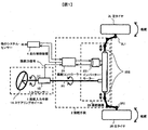
- FIG. 1 is an example of a configuration diagram of the front wheel steering system of the present embodiment.
- the front wheel steering system has a steering input means 1, a steering means 2, a left knuckle 3L1, a right knuckle 3R1, a left tire 3L, a right tire 3R, and a travel control device 4.
- the steering input means 1 includes a steering wheel 1A, a torque sensor 1B, and a connecting shaft 1C that are rotatably attached to a vehicle body of a passenger car.
- the steering means 2 includes a steering controller 2A, a steering mechanism 2B, and a lower connecting shaft 2C.
- the steering mechanism 2B includes an inverter motor 2B1, and the output portion of the steering mechanism is a rack end 2B2.
- the front wheel steering system performs both a turning operation based on a driver's steering operation (manual steering mode) and a turning operation based on a command from the travel control device (automatic steering mode).
- the steering input means transmits the rotational movement of the steering by the driver received by the steer wheel 1A to the connecting shaft, the torque sensor, and the lower connecting shaft, and transfers it to the steering mechanism 2B of the steering means 2.
- the torque sensor detects steering torque and outputs it as a steering force signal.
- the steering means 2 converts the rotational motion of the steering input to the steering mechanism 2B into a translational motion of the rack end 2B2 by an internal rack and pinion mechanism (not shown) and outputs the translational motion.
- the right knuckle 3R1 and the left knuckle 3L1 are rotatably attached to the vehicle body of the passenger car, and rotate themselves in response to the translational movement of the rack end. Since the right tire 3R and the left tire 3L are respectively attached to the right knuckle and the left knuckle, the respective tires are steered by the rotation of the knuckle, and a steering operation is performed.
- the steering controller 2A receives a steering force signal (steering torque value) from the torque sensor 1B.
- a steering force signal steering torque value
- the front wheel steering system performs the operation of assisting the steering driver with the torque of the electric motor, so the steering controller calculates the appropriate motor torque from the steering force signal and the vehicle running speed, etc. Output as steering force.
- the inverter motor 2B1 receives the target steering force, adjusts the voltage applied to the electric motor so as to obtain a steering force having the same magnitude as the target steering force, and generates and outputs a motor torque.
- the steering mechanism 2B receives the motor torque, converts it into a translation force to the rack end by an internal ball screw mechanism (not shown), and obtains and outputs the translation motion of the rack end by the translation force.
- the translation movement of the rack end is made by the total torque of both the steering torque by the driver and the motor torque. Therefore, the driver's steering operation is assisted by the motor.
- the traveling control device 4 receives information from other systems and sensors (not shown), and determines and outputs a steering (target steering angle) necessary for the vehicle to perform a desired traveling.
- the front wheel steering system performs an operation to adjust the actual steering angle to the target steering angle, so that the steering controller receives the target steering angle, the actual steering angle, the vehicle traveling speed, etc.
- the motor torque is calculated so that there is no difference between the target steering angle and the actual steering angle, and is output as the target steering force.
- the inverter motor receives the target steering force and generates and outputs motor torque in the same manner as in the manual steering mode.
- the steering mechanism 2B receives motor torque, converts it into a translational force in the rack end direction by an internal ball screw mechanism (not shown), and obtains and outputs the translational motion of the rack end with the translational force.
- the right knuckle 3R1 and the left knuckle 3L1 rotate, the right tire 3R and the left tire 3L are steered, and the steering angle (actual steering angle) of the tire is planned by the travel control device.
- the steering angle becomes necessary for traveling of the vehicle, and the operation by automatic steering is performed.
- the front wheel steering system needs to have a function of stopping the automatic steering mode and shifting to the manual steering mode when an input is given to the steering wheel during the operation by the automatic steering.
- the method for detecting the input to the steering wheel requires that a steering torque having such a magnitude that a change amount is observed in the rotation angle between the output shaft and the input shaft is input to the steering wheel. In the stage where the steering torque at the initial stage of steering wheel operation is small, a sufficient amount of change is not observed in the rotation angle between the output shaft and the input shaft, so switching is not performed.
- the automatic steering mode is continued even though the driver is operating the steering wheel, it takes time until the automatic steering is canceled after the driver performs the steering operation. For this reason, the driver feels resistance (uncomfortable feeling) in the operation of the steering wheel, and the resistance may cause the driver to operate the steering wheel with a greater force. For this reason, after the automatic steering is released, the steering wheel is excessively operated and the vehicle behavior may be disturbed as a result.
- the steering controller has processing for detecting that the driver has gripped the steering wheel, and when the driver grips the steering wheel, the input to the steering wheel is not detected. It detects that there is, and cancels the automatic steering mode and shifts to the manual steering mode.
- the driver can shift to the manual steering mode by grasping the steering wheel, it does not take time until the driver cancels the automatic steering after the steering operation is performed, and the driver resists the steering wheel operation ( I don't remember. Therefore, the steering wheel is not excessively operated. Therefore, it is possible to prevent the behavior of the vehicle from being disturbed.
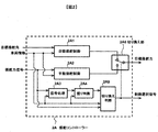
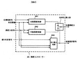
- FIG. 2 is an example of a processing block diagram inside the steering controller.
- the steering controller receives a target steering angle generated by the travel control device, vehicle information including vehicle travel speed, motor rotation angle, control mode switching information, steering wheel rotation angle information, and a steering force signal from a torque sensor.
- vehicle information including vehicle travel speed, motor rotation angle, control mode switching information, steering wheel rotation angle information, and a steering force signal from a torque sensor.
- a control selection signal indicating the target steering force and the switching state of the control mode is output.
- the automatic steering control unit 2A1 receives the target steering angle and the vehicle information, calculates a motor torque that eliminates the difference between the target steering angle and the actual steering angle, and outputs it as a target steering force.
- the manual steering control unit 2A2 receives a steering force signal and vehicle information, calculates an appropriate motor torque for assisting the driver's steering, and outputs it as a target steering force.
- the signal processing unit 2A3 receives the steering force signal, extracts a signal in a predetermined frequency region using, for example, a bandpass filter, and outputs the intensity of the extracted signal as a feature amount.
- the grip determination unit 2A4 receives the feature amount that is the intensity of the signal that has passed through the bandpass filter. For example, if the state where the feature amount is equal to or greater than a predetermined grip determination threshold value continues for a predetermined time or longer It is determined that the steering wheel is being gripped, and a grip determination is output.
- the switching determination unit 2A5 receives the grip determination, the steering force signal, and the vehicle information, finally determines whether to execute automatic steering control or manual steering control, and outputs it as a control selection signal.
- the switching unit 2A6 receives the target steering force by the automatic steering control, the target steering force by the manual steering control, and the control selection signal, and outputs the signal of the steering control unit specified by the control selection signal as the target steering force.
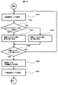
- FIG. 3 is an example of a switching flow from the automatic steering mode to the manual operation mode.
- the switching determination unit 2A5 is designated to perform the automatic steering control based on the control mode switching information from the travel control device included in the vehicle information, and automatically outputs the control selection signal. Steering control is selected. Therefore, the switching unit 2A6 selects the target steering force resulting from the automatic steering control unit. Therefore, the steering controller outputs the target steering force calculated by the automatic steering control unit.
- the signal processor receives the steering force signal and passes it through the bandpass filter.
- the pass frequency range of the bandpass filter does not substantially include the resonance frequency around the steering wheel, and is set to a frequency that is approximately lower than the resonance frequency.
- the steering wheel is slightly vibrating due to the vehicle vibration and the reaction force from the tire, and this is observed in the steering force signal.
- the moment of inertia around the steering wheel is increased by the driver holding the steering wheel, the resonance frequency around the steering wheel is lowered based on the laws of physics.
- the output of the signal processing unit is a high-intensity signal when the driver is holding the steering wheel.
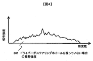
- FIG. 4 is an example 301 of signal strength in the frequency domain around the steering wheel when the driver is not gripping the steering wheel.
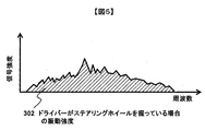
- FIG. 5 shows an example 302 of the signal strength in the frequency domain around the steering wheel when the driver is holding the steering wheel.
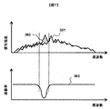
- FIG. 6 is an example of a comparison of signal strength in the frequency region around the steering wheel when the driver is holding the steering wheel and when the driver is not holding the steering wheel.
- the vibration characteristics change depending on the gripping state of the driver's steering wheel.
- the frequency drops.
- FIG. 7 shows an example of the relationship between the change in signal intensity in the frequency region around the steering wheel and the pass frequency characteristic 303 of the band-pass filter that does not include the resonance frequency and is set to a frequency that is approximately lower than the resonance frequency.
- the grip determination unit receives the feature amount that is the intensity of the signal that has passed through the bandpass filter, and the driver determines that the feature amount has exceeded a predetermined grip determination threshold for a predetermined time or longer. It is determined that the steering wheel is being gripped, and grip determination YES is output. If it is less than or equal to the threshold value, a grip determination NO is output.
- the grip determination is NO, and the process returns to the control flow F201 in the automatic steering mode to continue the automatic steering.
- the grip determination is YES, and the flow proceeds to the automatic steering release confirmation flow F203.
- the signal processing unit 2A3 only needs to be able to detect the phenomenon that the peak moves to the lower frequency side because the resonance frequency around the steering wheel is lowered when the driver grasps the steering wheel. It can also be configured using a filter (FIG. 8).
- the signal processing unit 2A3 performs a process of calculating a frequency characteristic of the steering force signal by executing, for example, a fast Fourier transform because the resonance frequency around the steering wheel is lowered when the driver grips the steering wheel.
- the grip determination unit 2A4 may extract a vibration intensity of a predetermined frequency that captures the change of the resonance frequency from the result of the Fourier transform, and use it as a feature amount. A change in the frequency of the peak frequency may be captured and used as a feature amount.
- the signal processing unit 2A3 receives the steering force signal, performs a calculation for estimating, for example, an inertia moment or mass around the steering wheel, and outputs the calculated inertia moment or mass as a feature amount.
- the grip determination unit 2A4 receives the feature amount and, for example, determines that the driver is gripping the steering wheel when the feature amount is equal to or greater than a predetermined grip determination threshold value for a predetermined period of time. It may output a grip determination.
- the resonance characteristic around the steering wheel varies depending on changes in the state of the vehicle and the driver. Therefore, the characteristic parameter of the band-pass filter or the low-pass filter of the signal processing unit 2A3 or the result of the Fourier transform is evaluated.
- the frequency or the like may be automatically adjusted by a learning function using vehicle travel history data, or may be adjusted according to the characteristics of the driver, for example, physique, gender, and age. May be. Further, the weight sensor provided on the seat or the driver's physique based on the amount of the seat belt pulled out may be determined and automatically adjusted.
- a large amount of features are detected to detect that the steering wheel is being gripped by automatically adjusting filter characteristic parameters or a predetermined frequency for evaluating the result of Fourier transform according to changes in vehicle and driver conditions. Therefore, a more reliable grip determination can be performed.
- the switching determination unit receives the grip determination, the steering force signal, and the vehicle information, determines whether to execute automatic steering control or manual steering control, and outputs a control selection signal. For example, even when the grip determination is YES, if the transition from the travel control device included in the vehicle information is prohibited to shift to manual steering control, a determination is made to continue automatic steering control.
- the selection signal is automatic steering control selection.
- the most suitable control mode can be selected by comprehensively selecting the steering control based not only on the grip judgment but also on the situation where the vehicle is placed.
- the process returns to the controlling flow F201 in the automatic steering mode and the automatic steering is continued. If the automatic steering mode can be canceled, the process proceeds to the control mode manual switching flow F204.
- control mode switching flow F204 the processing of the switching unit 2A6 is executed.
- the switching unit receives the target steering force based on the automatic steering control, the target steering force based on the manual steering control, and the control selection signal, and outputs the signal of the steering control unit designated by the control selection signal as the target steering force.
- the change processing is performed, and switching is performed so that the target steering force by the manual steering control unit is output.
- the process proceeds to control flow F205 in the manual steering mode.
- the change process of switching in the control mode switching flow F204 may be, for example, a change process that is switched once in a control cycle of the steering controller, or a change process that is gradually switched within the number of tens to thousands of cycles. .
- the switching change process in the control mode switching flow F204 is performed in a relatively short time when the reaction force input from the vehicle side to the steering wheel is small, for example, when traveling straight ahead, and the steering wheel when turning, for example. If the reaction force input from the vehicle side is large, a change process for switching over a relatively long time may be used.
- switching change processing in the control mode switching flow F204 may be performed by, for example, performing processing of mixing and outputting the target steering force by automatic steering control and the target steering force by manual steering control during switching.
- the switching change process in the control mode switching flow F204 is performed, for example, when the process of mixing and outputting the target steering force by the automatic steering control and the target steering force by the manual steering control is performed during the switching. You may perform the process which changes a ratio.
- the switching unit 2A6 selects the target steering force resulting from the manual steering control unit, and the steering controller outputs the target steering force calculated by the manual steering control unit.
- the front wheel steering system for a normal passenger vehicle determines the steering input from the driver during the control in the automatic steering mode by detecting the steering wheel grip by the driver.
- Automatic steering release processing can be started when the steering torque at the initial stage of wheel operation is small, and it takes no time from the driver's steering operation until the release of automatic steering. Canceling and switching to manual steering mode by the driver can prevent the driver from feeling uncomfortable and performing excessive operations to disturb the behavior of the vehicle.
- the value of the steering torque measured by the torque sensor is used.
- processing using the value of the rotation angle information of the steering wheel may be used, or the value of the rotation angle sensor to which the motor is attached.
- the process which uses may be sufficient, and the process which uses these in combination may be sufficient.
- the battery as the power source and the power supply wiring are not shown. Also, sensors and wiring for detecting the traveling speed of the automobile, the position of the motor rotor, etc. are not shown.
- the configuration is such that the vibration of the steering wheel generated by receiving a force such as a vehicle vibration or a reaction force from the tire is observed.
- the reaction force generation device may be driven to intentionally generate vibration, and the steering wheel vibration observed as a result may be observed.
- the characteristic amount for detecting that the steering wheel is being gripped is observed to be larger, so that more reliable grip determination can be performed.
- the steering input means is a steering wheel, it may take any form as long as it is held by a driver such as a joystick or lever.
- the steering device is configured to input the rotation of the steering wheel to the steering mechanism of the steering means.
- a steer-by-wire configuration in which torque is controlled and steering is performed only by the torque of the electric motor may be employed.
- the switching to the manual operation mode is determined from the signal in the steering system such as the steering torque.
- the switching to the manual operation mode is referred to by referring to the operation input of another system, for example, the brake system. You may judge.
- the driver requests cancellation of automatic steering by rotating the steering wheel while driving by automatic steering.
- FIG. 9 is an example of a processing block diagram inside the steering controller.
- the steering controller is a target steering angle generated by the travel control device, vehicle information including vehicle travel speed, motor rotation angle, control mode switching information, steering wheel rotation angle information, etc., a steering force signal from the torque sensor, and grip determination Upon receiving the signal, a control selection signal indicating the target steering force and the switching state of the control mode is output.
- the automatic steering control unit 2A1 receives the target steering angle and the vehicle information, calculates a motor torque that eliminates the difference between the target steering angle and the actual steering angle, and outputs it as a target steering force.
- the manual steering control unit 2A2 receives a steering force signal and vehicle information, calculates an appropriate motor torque for assisting the driver's steering, and outputs it as a target steering force.
- the switching determination unit 2A5 receives the grip determination, the steering force signal, and the vehicle information, finally determines whether to execute automatic steering control or manual steering control, and outputs it as a control selection signal.
- the switching unit 2A6 receives the target steering force by the automatic steering control, the target steering force by the manual steering control, and the control selection signal, and outputs the signal of the steering control unit specified by the control selection signal as the target steering force.
- the grip determination signal is supplied from the outside here, the present invention is not limited to this, and the grip determination signal may be calculated by performing calculation inside the steering controller.
- FIG. 10 is an example of a switching flow from the automatic steering mode to the manual operation mode.
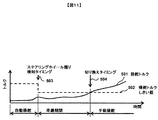
- FIG. 11 is an example of a diagram illustrating the change of the steering torque and the steering torque threshold based on the steering force signal and the switching timing in the switching from the automatic steering mode to the manual operation mode of the present embodiment.
- the horizontal axis represents time
- the vertical axis represents torque value.
- the switching determination unit 2A5 is designated to perform the automatic steering control by the control mode switching information from the travel control device included in the vehicle information, and automatically outputs the control selection signal for output. Steering control is selected. Therefore, the switching unit 2A6 selects the target steering force resulting from the automatic steering control unit. Therefore, the steering controller outputs the target steering force calculated by the automatic steering control unit. (Automatic steering section in FIG. 11) Next, from the steering wheel grip detection flow F302, the process of the switching determination unit 2A5 is executed. The switching determination unit receives the grip determination and sets a steering torque threshold value as a condition for shifting from the automatic steering mode to the manual steering mode.
- the normal value (a sufficiently large value to prevent switching from the automatic steering mode to the manual steering mode due to malfunction) is used as the steering torque threshold value. (F303). If it is determined that the driver is holding the steering wheel, a low value is set as the steering torque threshold value (F304).
- the steering force signal input to the switching determination unit 2A5 is referred to determine whether the threshold set in the previous flow is exceeded or not exceeded. For example, if the state where the steering torque based on the steering force signal is equal to or greater than the steering torque threshold continues for a predetermined time or longer, it is determined that the threshold is exceeded.
- the steering torque threshold value 502 is obtained by the above processing as shown by the steering wheel grip detection timing 503 in FIG. Reduce.
- the steering torque 501 increases as shown in FIG. 11 and exceeds the steering torque threshold at the switching timing 504.
- the switching timing is reached in a short time after the input of the steering torque to the steering wheel from the driver, and it is possible to shift to the manual steering mode.
- control mode switching flow F206 the processing of the switching unit 2A6 is executed.
- the switching unit receives the target steering force based on the automatic steering control, the target steering force based on the manual steering control, and the control selection signal, and outputs the signal of the steering control unit designated by the control selection signal as the target steering force.
- the selection signal is changed from the automatic steering control selection to the manual steering control selection, the changing process is executed, and finally, the target steering force by the manual steering control is output.
- the process proceeds to control flow F307 in the manual steering mode.
- the switching determination unit 2A5 uses the calculation result and the output control selection signal as the selection of the manual steering control. Therefore, the switching unit 2A6 selects the target steering force resulting from the manual steering control unit. Therefore, the steering controller outputs the target steering force calculated by the manual steering control unit.
- the front wheel steering system for a normal passenger car provides a preparation period based on detection of the steering wheel grip by the driver during control in the automatic steering mode, and shifts to manual steering.
- the threshold value for judging the switching of the vehicle it takes no time from the driver performing the steering operation until the automatic steering is canceled, and the automatic steering mode is quickly canceled and the manual steering mode by the driver is performed. It can be seen that it is possible to prevent the driver from disturbing the behavior of the vehicle by performing excessive operations with a sense of incongruity.
- the driver steering controller drives the motor or steering wheel excitation device or steering wheel reaction force generation device to intentionally generate vibrations, and the resulting steering wheel vibrations are observed.
- the automatic steering mode may be switched to the manual control mode. By deliberately generating vibration, the feature quantity used for the determination is observed to be larger, so that more reliable determination can be performed.
- the driver steering controller drives the motor or steering wheel excitation device or steering wheel reaction force generation device to intentionally generate vibrations. Observation may be made and the automatic steering mode may be switched to the manual control mode when the amplitude becomes smaller than a predetermined threshold value. A more reliable determination can be performed by intentionally generating vibration and using an easily measurable amplitude for the feature amount used for the determination.
- the vibration of the steering wheel may be a torque vibration in the rotation direction of the steering wheel, an amplitude of a displacement angle, or a vibration of force in the steering wheel axial direction. It may be the amplitude of the displacement.
- the driver requests cancellation of automatic steering by rotating the steering wheel while driving by automatic steering.
- this invention is not limited to the above-mentioned Example, Various modifications are included.
- the above-described embodiments have been described in detail for easy understanding of the present invention, and are not necessarily limited to those having all the configurations described.
- a part of the configuration of one embodiment can be replaced with the configuration of another embodiment, and the configuration of another embodiment can be added to the configuration of one embodiment.
- each of the above-described configurations, functions, processing units, processing means, and the like may be realized by hardware by designing a part or all of them with, for example, an integrated circuit.
- Each of the above-described configurations, functions, and the like may be realized by software by interpreting and executing a program that realizes each function by the processor.
- the control lines and information lines indicate what is considered necessary for the explanation, and not all the control lines and information lines on the product are necessarily shown. Actually, it may be considered that almost all the components are connected to each other.
- SYMBOLS 1 Steering input means, 1A ... Steering wheel, 1B ... Torque sensor, 2 ... Steering means, 2A ... Steering controller, 2B ... Steering mechanism, 2B1 ... Inverter motor, 2B2 ... Rack end, 3L ... Left tire, 3L1 ... Left Knuckle, 3R ... Right tire, 3R1 ... Right knuckle, 4 ...
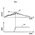
- Driving control device 301 ... Signal strength in frequency region around the steering wheel when the driver is not holding the steering wheel, 302 ... Driver holding the steering wheel Signal intensity in the frequency region around the steering wheel, 303 ... band-pass filter shielding characteristics, 304 ... low-pass filter shielding characteristics
Landscapes
- Engineering & Computer Science (AREA)
- Chemical & Material Sciences (AREA)
- Combustion & Propulsion (AREA)
- Transportation (AREA)
- Mechanical Engineering (AREA)
- Steering Control In Accordance With Driving Conditions (AREA)
Abstract
ドライバーからの操舵入力がステアリングホイールにあった場合、速やかに自動操舵モードを解除しドライバーによる手動操舵モードへの切り換えを実行し、ドライバーが違和感を覚えて過剰な操作を行い車両の挙動を乱すことを防止できる方法及び装置を提供する。本発明に係る車両用操舵装置は、ドライバーが、操舵入力手段(1)の入力部(1A)を握っていることを、操舵入力手段(1)の入力部(1A)とそれに付随する質量、あるいは、慣性モーメントが増加したことによる特徴変化で検出し、握っていることの検出結果に基づいて自動操舵モードと手動操舵モードの切り換え動作を行う。
Description
本発明は、自動操舵機能を持つ車両操舵装置に関する。
本技術分野の背景技術として、特開2002-200985号公報(特許文献1)がある。この公報には、出力軸の回転角が入力軸の回転角よりも先に変化し、かつ、一定時間内における入力軸の回転角の変化量が所定値以下であれば、ドライバーがステアリングホイールから手を放したと判断されて、車両が道路上の車線に沿って走行するようにステアリング機構を自動操舵する自動操舵モードにされる。
そして、自動操舵が行われている状態で、入力軸の回転角が出力軸の回転角よりも先に変化すれば、ドライバーによってステアリングホイールが操作されたと判断され、ドライバーによるステアリングホイールの操作に基づいて電動モーターを駆動し、電動モーターから発生されるトルクをステアリング機構に与えて操舵補助を行うアシストモードに切り換えられる、と記載されている。
特許文献1では、自動操舵モードからドライバーによるステアリングホイールが操作される手動操舵モード(アシストモード)への切り換え判断が成されるには、出力軸と入力軸の回転角度に変化量が観測される大きさの操舵トルクがステアリングホイールに入力されることが必要となる。ここで、ステアリングホイール操作初期の操舵トルクが小さい段階では、出力軸と入力軸の回転角度に十分な変化量が観測される状態に至らないため、切り換えが実施されない。
すなわち、ドライバーがステアリングホイールを操作しているにもかかわらず、自動操舵モードが継続されてしまうこととなる。このため、ドライバーが違和感を覚え過剰な操作を行い車両の挙動を乱してしまうため、安全な走行ができない可能性がある。
そこで、本発明の目的は、ドライバーからの操舵入力がステアリングホイールにあった場合、速やかに自動操舵モードを解除しドライバーによる手動操舵モードへの切り換えを実行し、ドライバーが違和感を覚えて過剰な操作を行い車両の挙動を乱すことを防止できる方法及び装置を提供することにある。
上記課題を解決するために、例えば特許請求の範囲に記載の構成を採用する。本願は上記課題を解決する手段を複数含んでいるが、その一例を挙げるならば本発明の特徴は、以下の通りである。
ドライバーによる操舵を検出する操舵入力手段と、走行制御を実行する走行制御装置と、操舵入力手段に入力された操舵、あるいは、走行制御装置の計算する操舵位置に基づいて自動車のタイヤの操舵を行う操舵手段とを備え、ドライバーによる操舵に基づく手動操舵モードと走行制御装置の計算結果に基づく自動操舵モードでの動作を行える車両用操舵装置であって、
ドライバーが、操舵入力手段の入力部を握っていることを、操舵入力手段の入力部と、それに付随する質量、あるいは、慣性モーメントが増加したことによる特徴変化で検出し、握っていることの検出結果に基づいて自動操舵モードと手動操舵モードの切り換え動作を行う工程、を持つ車両の操舵装置に特徴がある。
ドライバーが、操舵入力手段の入力部を握っていることを、操舵入力手段の入力部と、それに付随する質量、あるいは、慣性モーメントが増加したことによる特徴変化で検出し、握っていることの検出結果に基づいて自動操舵モードと手動操舵モードの切り換え動作を行う工程、を持つ車両の操舵装置に特徴がある。
本発明によれば、自動操舵モードで制御されている最中にドライバーからの操舵入力がステアリングホイールにあった場合、速やかに自動操舵を解除し手動操舵に切り換えることを実現でき、ドライバーが違和感を覚えて過剰な操作を行い車両の挙動を乱すことを防止できる装置を提供できる。上記した以外の課題、構成及び効果は、以下の実施形態の説明により明らかにされる。
実施例を用いて本発明の実施形態を説明する。
本実施例では、普通乗用車の前輪操舵システムの例について、図1から図8を用いて説明する。
図1は、本実施例の前輪操舵システムの構成図の例である。
前輪操舵システムは、操舵入力手段1、操舵手段2、左ナックル3L1、右ナックル3R1、左タイヤ3L、右タイヤ3R、走行制御装置4、を有する。操舵入力手段1は、乗用車の車体に回転自由に取り付けられたステアリングホイール1A、トルクセンサー1B、連結シャフト1Cから成る。操舵手段2は、操舵コントローラー2A、操舵機構2B、下部連結シャフト2Cから成る。また、操舵機構2Bはインバーター・モーター2B1を含み、操舵機構の出力部はラックエンド2B2である。
前輪操舵システムは、ドライバーの操舵操作に基づく転舵動作(手動操舵モード)と走行制御装置の指令に基づく転舵動作(自動操舵モード)の両方の動作を行う。
手動操舵モードの場合、操舵入力手段は、ステアリンホイール1Aで受けたドライバーによる操舵の回転運動を連結シャフト、トルクセンサー、下部連結シャフトと伝達し、操舵手段2の操舵機構2Bに受け渡す。また、トルクセンサーは、操舵トルクを検出し、操舵力信号として出力する。操舵手段2は、操舵機構2Bに入力された操舵の回転運動を内部の図示しないラックアンドピニオン機構によってラックエンド2B2の並進運動に変換して出力する。右ナックル3R1および左ナックル3L1は、乗用車の車体に回転自由に取り付けられていて、ラックエンドの並進運動を受けて自身が回転する。右タイヤ3Rおよび左タイヤ3Lはそれぞれ、右ナックル、左ナックルに取り付けられているので、ナックルの回転によりそれぞれのタイヤが転舵し、転舵動作が行われる。
操舵コントローラー2Aは、トルクセンサー1Bからの操舵力信号(操舵トルクの値)を受ける。手動操舵モードでは、前輪操舵システムは、操舵ドライバーの操舵を電気モーターによるトルクでアシストする動作を行うので、操舵コントローラーは、操舵力信号と自動車の走行速度などより適切なモータートルクを計算し、目標操舵力として出力する。
インバーター・モーター2B1は、目標操舵力を受け、目標操舵力と等しい大きさの操舵力が得られるように電気モーターに印加する電圧を調整してモータートルクを発生させ、出力する。操舵機構2Bは、モータートルクを受け、内部の図示しないボールねじ機構によってラックエンドへの並進力に変換し、その並進力でラックエンドの並進運動を得て出力する。
すなわち、ラックエンドの並進運動は、ドライバーによる操舵トルクとモータートルクの双方の合計トルクによって成される。よって、ドライバーの操舵動作がモーターによりアシストされる動作となる。
自動操舵モードでは、ドライバーはステアリングホイールを握っておらず、手動操舵モードのようなステアリングホイールへの回転入力は無いとする。走行制御装置4は、図示しない他のシステムやセンサーからの情報を受け、車両が所望の走行となるために必要な操舵(目標操舵角)を決定し出力する。自動操舵モードでは、前輪操舵システムは、目標操舵角に実操舵角が一致するように調整する動作を行うので、操舵コントローラーは、目標操舵角と実操舵角と車両の走行速度などを受けて、目標操舵角と実舵角の差が無くなるようにモータートルクを計算し、目標操舵力として出力する。
インバーター・モーターは、目標操舵力を受けて、手動操舵モードの場合と同様に、モータートルクを発生させ出力する。操舵機構2Bは、モータートルクを受け、内部の図示しないボールねじ機構によってラックエンド方向の並進力に変換し、並進力でラックエンドの並進運動を得て出力する。以下、手動操モードの場合と同様に、右ナックル3R1および左ナックル3L1が回転し、右タイヤ3Rおよび左タイヤ3Lが転舵して、タイヤの舵角(実舵角)は走行制御装置で計画された車両の走行に必要な舵角となり、自動操舵による動作が行われる。
ここで、自動操舵による動作を行っている最中にドライバーが自動操舵の解除を要求する場合、ドライバーがステアリングホイールを回転させて意図する車両運動を得ようとする場合がある。よって、前輪操舵システムは、自動操舵による動作を行っている最中にステアリングホイールに入力が与えられた場合、自動操舵モードを中止し手動操舵モードに移行する機能を持つ必要がある。
ステアリングホイールへの入力を検知するため方法は、従来の例では、出力軸と入力軸の回転角度に変化量が観測される大きさの操舵トルクがステアリングホイールに入力されることが必要となるので、ステアリングホイール操作初期の操舵トルクが小さい段階では、出力軸と入力軸の回転角度に十分な変化量が観測される状態に至らないため、切り換えが実施されない。
すなわち、ドライバーがステアリングホイールを操作しているにもかかわらず、自動操舵モードが継続されてしまうこととなるため、ドライバーが操舵動作を行ってから自動操舵の解除に至るまでに時間がかかる。このため、ドライバーはステアリングホイールの操作に抵抗(違和感)を覚え、抵抗があるためさらに大きな力でステアリングホイールを操作することがある。そのため、自動操舵解除後に勢いあまってステアリングホイールを過剰操作してしまい、結果として車両の挙動を乱してしまうことがある。
本実施例ではステアリングホイールへの入力を検知するため方法として、ステアリングホイールをドライバーが握ったことを感知する処理を操舵コントローラー内に持ち、ドライバーがステアリングホイールを握ったことでステアリングホイールへの入力があると検知し、自動操舵モードを中止し手動操舵モードに移行する。
これにより、ドライバーがステアリングホイールを握ったことにより手動操舵モードに移行できるのでドライバーが操舵動作を行ってから自動操舵の解除に至るまでに時間がかからず、ドライバーはステアリングホイールの操作に抵抗(違和感)を覚え無い。よって、ステアリングホイールを過剰に操作することも無い。よって、車両の挙動を乱してしまうことも防止できる。
図2は、操舵コントローラーの内部の処理ブロック図の例である。
操舵コントローラーは、走行制御装置で生成される目標操舵角と、車両走行速度やモーター回転角度、制御モード切り換え情報、ステアリングホイール回転角度情報などからなる車両情報と、トルクセンサーによる操舵力信号を受け、目標操舵力と、制御モードの切り換え状態を示す制御選択信号を出力する。
自動操舵制御部2A1は、目標操舵角と車両情報を受けて、目標操舵角と実舵角の差が無くなるようにするモータートルクを計算し、目標操舵力として出力する。手動操舵制御部2A2は、操舵力信号と車両情報を受けて、ドライバーの操舵をアシストする適切なモータートルクを計算し、目標操舵力として出力する。
信号処理部2A3は、操舵力信号を受けて、例えば、バンドパスフィルターを用いて所定の周波数領域の信号を抽出し、抽出した信号の強度を特徴量として出力する。
信号処理部2A3は、操舵力信号を受けて、例えば、バンドパスフィルターを用いて所定の周波数領域の信号を抽出し、抽出した信号の強度を特徴量として出力する。
握り判断部2A4は、バンドパスフィルターを通過した信号の強度である特徴量を受けて、例えば、特徴量が予め設定した握り判断しきい値以上となる状態が所定の時間以上継続した場合ドライバーがステアリングホイールを握っていると判断し、握り判定を出力する。
切り換え判断部2A5は、握り判定と操舵力信号と車両情報を受けて、最終的に自動操舵制御と手動操舵制御のどちらを実行するか判断を行い、制御選択信号として出力する。
切り換え部2A6は、自動操舵制御による目標操舵力と手動操舵制御による目標操舵力と制御選択信号を受けて、制御選択信号で指定された操舵制御部の信号を目標操舵力として出力する。
図3は、自動操舵モードから手動操作モードへの切り換えフローの例である。
以下、本実施例におけるステアリングホイールに入力が与えられた場合に自動操舵モードを中止し手動操舵モードに移行する動作を説明する。
自動操舵モードで制御フローF201においては、切り換え判断部2A5は、車両情報に含まれる走行制御装置からの制御モード切り換え情報により自動操舵制御を行うことを指定されていて、出力の制御選択信号を自動操舵制御の選択としている。よって、切り換え部2A6は、自動操舵制御部の結果の目標操舵力を選択している。したがって、操舵コントローラーは自動操舵制御部が計算した目標操舵力を出力している。
次に、ステアリングホイール握り検出フローF202において、信号処理部2A3、握り判断部2A4での処理を実行する。
信号処理部では、操舵力信号を受けて、それをバンドパスフィルターに通す。ここで、バンドパスフィルターの通過周波数域は、ステアリングホイール周りの共振周波数をおおよそ含まず、共振周波数よりもおおよそ低い周波数に設定されている。
つまり、ステアリングホイールは車両の振動やタイヤからの反力などの力を受けてわずかであるが振動をしていて、これが操舵力信号に観測されている。ドライバーがステアリングホイールを握ることによってステアリングホイール周りの慣性モーメントが増加すると、物理法則に基づきステアリングホイール周りの共振周波数が下がる。
すると、共振のピーク周波数は、バンドパスフィルターが通過させる周波数帯に移動してくるので、バンドパスフィルターを通過した信号の強度である特徴量は、ドライバーがステアリングホイールを握っていない場合は小さく、ドライバーがステアリングホイールを握っている場合は大きくなる。すなわち、信号処理部の出力は、ドライバーがステアリングホイールを握っている場合に強度の高い信号となる。
図4は、ドライバーがステアリングホイールを握っていない場合のステアリングホイール周りの周波数領域での信号強度の例301である。
図5は、ドライバーがステアリングホイールを握っている場合のステアリングホイール周りの周波数領域での信号強度の例302である。
図6は、ドライバーがステアリングホイールを握っている場合と握っていない場合のステアリングホイール周りの周波数領域での信号強度の比較の例である。
図4、5、6の例で示すように、ドライバーのステアリングホイールの握りの状態によって、振動特性が変わり、振動特性で高い値を示す共振周波数は、ドライバーのステアリングホイールを握ることによって顕著にその周波数が低下する。
図7は、ステアリングホイール周りの周波数領域での信号強度の変化と、共振周波数をおおよそ含まず、共振周波数よりもおおよそ低い周波数に設定したバンドパスフィルターの通過周波数特性303の関係の例である。
続く、握り判断部は、バンドパスフィルターを通過した信号の強度である特徴量を受けて、特徴量が予め設定した握り判断しきい値以上となる状態が所定の時間以上継続した場合にドライバーがステアリングホイールを握っていると判断し、握り判定YESを出力する。しきい値以下の場合は握り判定NOを出力する。
ドライバーがステアリングホイールを握っていない場合は、握り判定がNOとなり、自動操舵モードでの制御中フローF201に戻り自動操舵を継続する。
ドライバーがステアリングホイールを握っている場合は、握り判定がYESとなり、自動操舵解除確認フローF203に進む。
なお、信号処理部2A3は、ドライバーがステアリングホイールを握るとステアリングホイール周りの共振周波数が下がるので、より低周波側にピークが移動する現象を検出できれば良いので、低周波側の振動を通過させるローパスフィルターを用いて構成することもできる(図8)。
なお、信号処理部2A3は、ドライバーがステアリングホイールを握るとステアリングホイール周りの共振周波数が下がるので、例えば高速フーリエ変換を実行して操舵力信号の周波数特性を計算する処理を行うものであって、握り判断部2A4は、フーリエ変換の結果から、共振周波数が変化することを捉えられる所定の周波数の振動強度を抽出し、特徴量とするものであっても良いし、フーリエ変換の結果から、共振ピーク周波数の振動数の変化を捉えて特徴量とするものであっても良い。
なお、信号処理部2A3は、操舵力信号を受けて、例えばステアリングホイール周りの慣性モーメント、あるいは質量を推定する計算を実施し、算出した慣性モーメント、あるいは質量を特徴量として出力するものであって、握り判断部2A4は、特徴量を受けて、例えば、特徴量が予め設定した握り判断しきい値以上となる状態が所定の時間以上継続した場合ドライバーがステアリングホイールを握っていると判断し、握り判定を出力するものであっても良い。
なお、ステアリングホイール周りの共振の特性は、車両やドライバーの状態の変化によって変動するものであるので、信号処理部2A3のバンドパスフィルターまたはローパスフィルターの特性パラメーターまたはフーリエ変換の結果を評価する所定の周波数などは、車両の走行履歴データを用いて学習機能により自動的に調整されるものであっても良いし、ドライバーの特徴、例えば、体格や性別、年齢などに応じて調整されるものであっても良い。また、シートに設けられた体重センサーあるいは、シートベルト引き出し量に基づき運転者の体格を判断して自動的に調整されるものであっても良い。
車両やドライバーの状態の変化に合わせて、フィルターの特性パラメーターまたはフーリエ変換の結果を評価する所定の周波数などを自動調整することで、ステアリングホイールを握っていることを検出する特徴量がより大きく観測されるので、より確実な握り判定を実施できる。
自動操舵解除確認フローF203では、切り換え判断部2A5の処理を実行する。切り換え判断部は、握り判定と操舵力信号と車両情報を受けて、自動操舵制御と手動操舵制御のどちらを実行するかの判断を行い、制御選択信号を出力する。例えば、握り判定がYESの場合であっても、車両情報に含まれる走行制御装置からの信号で、手動操舵制御への移行が禁止されている場合は、自動操舵制御を継続する判断を行い、選択信号を自動操舵制御選択とする。
これにより、握り判断だけでなく車両のおかれている状況から総合的に操舵制御の選択を行うことで、最も適する制御モードを選択できるようになる。
ここで、自動操舵モードを解除できない場合は、自動操舵モードでの制御中フローF201に戻り自動操舵を継続する。自動操舵モードの解除可能な場合は、制御モードの手動切り換えフローF204に進む。
ここで、自動操舵モードを解除できない場合は、自動操舵モードでの制御中フローF201に戻り自動操舵を継続する。自動操舵モードの解除可能な場合は、制御モードの手動切り換えフローF204に進む。
制御モード切り換えフローF204では、切り換え部2A6の処理を実行する。切り換え部は、自動操舵制御による目標操舵力と手動操舵制御による目標操舵力と制御選択信号を受けて、制御選択信号で指定された操舵制御部の信号を目標操舵力として出力する。ここで、選択信号として自動操舵制御選択から手動操舵制御選択に変更となった場合は、変更処理を実施し、手動操舵制御部による目標操舵力を出力するように切り換える。切り換えのあと、手動操舵モードで制御フローF205に進む。
なお、制御モード切り換えフローF204での切り換えの変更処理は、例えば、操舵コントローラーの制御周期1回で切り換える変更処理でも良いし、数十から数千周期の回数の内に徐々に切り換える変更処理でも良い。
なお、制御モード切り換えフローF204での切り換え変更処理は、例えば、直進走行時などでステアリングホイールに車両側から入力される反力が小さい場合は比較的短い時間で切り換え、旋回走行時などでステアリングホイールに車両側から入力される反力が大きい場合は比較的長い時間で切り換える変更処理でも良い。
なお、制御モード切り換えフローF204での切り換え変更処理は、例えば、切り換える間に自動操舵制御による目標操舵力と手動操舵制御による目標操舵力を混合して出力する処理を行っても良い。
なお、制御モード切り換えフローF204での切り換え変更処理は、例えば、切り換える間に、自動操舵制御による目標操舵力と手動操舵制御による目標操舵力を混合して出力する処理を行う場合、徐々にその混合比率を変更させる処理を行っても良い。
手動操舵モードで制御フローF205においては、切り換え部2A6は、手動操舵制御部の結果の目標操舵力を選択し、操舵コントローラーは手動操舵制御部が計算した目標操舵力を出力する。
このようにして、本発明の一実施形態による普通乗用車の前輪操舵システムは、自動操舵モードでの制御中にドライバーからの操舵入力を、ドライバーによるステアリングホイールの握りの検出で判断することで、ステアリングホイール操作初期の操舵トルクが小さい段階で自動操舵の解除処理を開始することができ、ドライバーが操舵動作を行ってから自動操舵の解除に至るまでに時間がかからず、速やかに自動操舵モードを解除しドライバーによる手動操舵モードへの切り換えを実行し、ドライバーが違和感を覚えて過剰な操作を行い車両の挙動を乱すことを防止できる。
なお、本実施例ではトルクセンサーが測定する操舵トルクの値を用いているが、ステアリングホイールの回転角度情報の値を用いる処理であっても良いし、モーターの取り付けられている回転角センサーの値を用いる処理であっても良いし、これらを組み合わせて用いる処理であっても良い。ステアリングホイールの回転角度情報の値を用いる処理やモーターの取り付けられている回転角センサーの値を用いる処理とすることで、トルクセンサーが故障した場合にも本実施例の制御を実行することができる。
なお、図中、動力源であるバッテリや給電の配線などは図示していない。また、自動車の走行速度、モーターローターの位置などを検出するセンサーや配線などは図示していない。
なお、本実施例では、車両の振動やタイヤからの反力などの力を受けて発生するステアリングホイールの振動を観測する構成としたが、操舵コントローラーでモーターあるいはステアリングホイールの加振装置あるいはステアリングホイールの反力生成装置を駆動して故意に振動を発生させ、その結果観測されるステアリングホイールの振動を観測する構成であっても良い。故意に振動を発生させることで、ステアリングホイールを握っていることを検出する特徴量がより大きく観測されるので、より確実な握り判定を実施できる。
なお、操舵入力手段はステアリングホイールとしたが、ジョイススティックやレバー等のドライバーが手で握るものであれば、どのような形態でも良い。
なお、操舵装置はステアリングホイールの回転を操舵手段の操舵機構に入力する構成を示したが、ステアリングホイールと操舵機構を機械的に連結せずにトルクセンサーの検出した操舵トルクに基づいて電気モーターのトルクを制御し、電気モーターのトルクのみで転舵を行うステア・バイ・ワイヤの構成であっても良い。
なお、本実施例では手動操作モードへの切り換えを操舵トルクなどのステアリングシステム内の信号から判断するとしたが、他のシステム、例えばブレーキシステムの操作入力等を参照して、手動操作モードへの切り換えを判断しても良い。
なお、本実施例では手動操作モードへの切り換えを操舵トルクなどのステアリングシステム内の信号から判断するとしたが、他のシステム、例えばブレーキシステムの操作入力等を参照して、手動操作モードへの切り換えを判断しても良い。
なお、本実施例の前輪操舵システムにおける自動操舵の解除機能が正常にはたらいていることを確認する方法として、ステアリングホイールにばねなどを用いて回転トルクを与えた場合とステアリングホイールに質量を負荷してからばねなどを用いて回転トルクを与えた場合の両者の解除タイミングを比較し、量を負荷してからばねなどを用いて回転トルクを与えた場合の方が解除に至る時間が短いことをもって正常に作動していると判断することができる。
以上、本実施の形態によれば、自動操舵機能を持つ車両操舵装置に関して、自動操舵による運転を行っている最中にドライバーが自動操舵の解除を、ステアリングホイールを回転させて要求する場合であっても速やかに自動操舵を解除し手動操舵に切り換え、ドライバーが違和感を覚えて過剰な操作を行い車両の挙動を乱すことを防止できる装置を提供することができる。
以下、本発明の第二の実施の形態に係る普通乗用車の前輪操舵システムの例について、図9から図11を用いて説明する。
実施例1と同様の構成である部分の説明は省略し、本実施例の特徴的な部分について、まずその構成を説明する。
図9は、操舵コントローラーの内部の処理ブロック図の例である。
操舵コントローラーは、走行制御装置で生成される目標操舵角と、車両走行速度やモーター回転角度、制御モード切り換え情報、ステアリングホイール回転角度情報などからなる車両情報と、トルクセンサーによる操舵力信号と握り判定信号を受け、目標操舵力と、制御モードの切り換え状態を示す制御選択信号を出力する。
自動操舵制御部2A1は、目標操舵角と車両情報を受けて、目標操舵角と実舵角の差が無くなるようにするモータートルクを計算し、目標操舵力として出力する。手動操舵制御部2A2は、操舵力信号と車両情報を受けて、ドライバーの操舵をアシストする適切なモータートルクを計算し、目標操舵力として出力する。
切り換え判断部2A5は、握り判定と操舵力信号と車両情報を受けて、最終的に自動操舵制御と手動操舵制御のどちらを実行するか判断を行い、制御選択信号として出力する。
切り換え判断部2A5は、握り判定と操舵力信号と車両情報を受けて、最終的に自動操舵制御と手動操舵制御のどちらを実行するか判断を行い、制御選択信号として出力する。
切り換え部2A6は、自動操舵制御による目標操舵力と手動操舵制御による目標操舵力と制御選択信号を受けて、制御選択信号で指定された操舵制御部の信号を目標操舵力として出力する。
なお、ここで握り判定信号は外部から供給されるとしたが、これに限定するものでは無く、操舵コントローラー内部で計算を行って握り判定信号を算出しても良い。
図10は、自動操舵モードから手動操作モードへの切り換えフローの例である。
図11は、本実施例の自動操舵モードから手動操作モードへの切り換えにおける、操舵力信号による操舵トルクと操舵トルクしきい値の変化と切り換えのタイミングを示した図の例である。なお、図11の横軸は時間、縦軸はトルク値である
以下、本実施例におけるステアリングホイールに入力が与えられた場合に自動操舵モードを中止し手動操舵モードに移行する動作を説明する。
以下、本実施例におけるステアリングホイールに入力が与えられた場合に自動操舵モードを中止し手動操舵モードに移行する動作を説明する。
自動操舵モードで制御フローF301においては、切り換え判断部2A5は、車両情報に含まれる走行制御装置からの制御モード切り換え情報により自動操舵制御を行うことを指定されていて、出力の制御選択信号を自動操舵制御の選択としている。よって、切り換え部2A6は、自動操舵制御部の結果の目標操舵力を選択している。したがって、操舵コントローラーは自動操舵制御部が計算した目標操舵力を出力している。(図11の自動操舵の区間)
次に、ステアリングホイール握り検出フローF302からは、切り換え判断部2A5の処理を実行する。切り換え判断部は、握り判定を受けて、自動操舵モードから、手動操舵モードに移る条件となる操舵トルクしきい値を設定する。すなわち、ドライバーがステアリングホイールを握っていない判断の場合は、通常の値(誤作動による自動操舵モードから手動操舵モードへの切り換えを防止するため、十分に大きな値)を操舵トルクしきい値とする(F303)。また、ドライバーがステアリングホイールを握っている判断の場合は、低い値を操舵トルクしきい値とする(F304)。
次に、ステアリングホイール握り検出フローF302からは、切り換え判断部2A5の処理を実行する。切り換え判断部は、握り判定を受けて、自動操舵モードから、手動操舵モードに移る条件となる操舵トルクしきい値を設定する。すなわち、ドライバーがステアリングホイールを握っていない判断の場合は、通常の値(誤作動による自動操舵モードから手動操舵モードへの切り換えを防止するため、十分に大きな値)を操舵トルクしきい値とする(F303)。また、ドライバーがステアリングホイールを握っている判断の場合は、低い値を操舵トルクしきい値とする(F304)。
操舵トルク判定フローF305においては、切り換え判断部2A5に入力されている操舵力信号を参照し、先のフローで設定したしきい値を超えているか超えていないかの判断を行う。例えば、操舵力信号による操舵トルクが操舵トルクしきい値以上となる状態が所定の時間以上継続した場合、しきい値を超えていると判断する。
ここで、自動操舵モードの最中に、ドライバーがステアリングホイールを握っていることを検知した場合、上記の処理により、図11のステアリングホイール握り検知タイミング503で示すように、操舵トルクしきい値502を低下させる。ここで、ドライバーからのステアリングホイールへの操舵トルクの入力が始まると、図11に示すように操舵トルク501が上昇し、切り換えタイミング504で操舵トルクしきい値を超える。このように、操舵トルクしきい値502を低下させているので、ドライバーからのステアリングホイールへの操舵トルクの入力が始まってから短時間で切り換えタイミングとなり、手動操舵モードに移行することができる。
制御モード切り換えフローF206では、切り換え部2A6の処理を実行する。切り換え部は、自動操舵制御による目標操舵力と手動操舵制御による目標操舵力と制御選択信号を受けて、制御選択信号で指定された操舵制御部の信号を目標操舵力として出力する。ここで、選択信号として自動操舵制御選択から手動操舵制御選択に変更となった場合は、変更処理を実施し、最終的には手動操舵制御による目標操舵力を出力するように切り換える。切り換えのあと、手動操舵モードで制御フローF307に進む。
手動操舵モードで制御フローF307においては、切り換え判断部2A5は、上記の計算結果、出力の制御選択信号を手動操舵制御の選択としている。よって、切り換え部2A6は、手動操舵制御部の結果の目標操舵力を選択している。したがって、操舵コントローラーは手動操舵制御部が計算した目標操舵力を出力している。
このようにして、本発明の第二の実施の形態による普通乗用車の前輪操舵システムは、自動操舵モードでの制御中にドライバーによるステアリングホイールの握りの検出に基づいて準備期間を設け、手動操舵への切り換えを判断するしきい値を低下させることで、ドライバーが操舵動作を行ってから自動操舵の解除に至るまでに時間がかからず、速やかに自動操舵モードを解除しドライバーによる手動操舵モードへの切り換えを実行し、ドライバーが違和感を覚えて過剰な操作を行い車両の挙動を乱すことを防止できることがわかる。
また、準備期間においては、ドライバー操舵コントローラーでモーターあるいはステアリングホイールの加振装置あるいはステアリングホイールの反力生成装置を駆動して故意に振動を発生させ、その結果観測されるステアリングホイールの振動を観測して自動操舵モードから手動制御モードに切り換える構成であっても良い。故意に振動を発生させることで、判断に用いる特徴量がより大きく観測されるので、より確実な判定を実施できる。
また、準備期間においては、ドライバー操舵コントローラーでモーターあるいはステアリングホイールの加振装置あるいはステアリングホイールの反力生成装置を駆動して故意に振動を発生させ、その結果観測されるステアリングホイールの振動の振幅を観測し、この振幅が所定のしきい値より小さくなった場合に自動操舵モードから手動制御モードに切り換える構成であっても良い。故意に振動を発生させることと、判断に用いる特徴量に計測が容易な振幅を用いることで、より確実な判定を実施できる。なお、ステアリングホイールの振動とは、ステアリングホイールの回転方向のトルクの振動であっても良いし、変位角の振幅であっても良いし、ステアリングホイール軸方向の力の振動であっても良いし変位の振幅であっても良い。
以上、本実施の形態によれば、自動操舵機能を持つ車両操舵装置に関して、自動操舵による運転を行っている最中にドライバーが自動操舵の解除を、ステアリングホイールを回転させて要求する場合であっても速やかに自動操舵を解除し手動操舵に切り換え、ドライバーが違和感を覚えて過剰な操作を行い車両の挙動を乱すことを防止できる装置を提供することができる。
なお、本発明は上記した実施例に限定されるものではなく、様々な変形例が含まれる。例えば、上記した実施例は本発明を分かりやすく説明するために詳細に説明したものであり、必ずしも説明した全ての構成を備えるものに限定されるものではない。また、ある実施例の構成の一部を他の実施例の構成に置き換えることが可能であり、また、ある実施例の構成に他の実施例の構成を加えることも可能である。また、各実施例の構成の一部について、他の構成の追加・削除・置換をすることが可能である。
また、上記の各構成、機能、処理部、処理手段等は、それらの一部又は全部を、例えば集積回路で設計する等によりハードウェアで実現してもよい。また、上記の各構成、機能等は、プロセッサがそれぞれの機能を実現するプログラムを解釈し、実行することによりソフトウェアで実現してもよい。また、制御線や情報線は説明上必要と考えられるものを示しており、製品上必ずしも全ての制御線や情報線を示しているとは限らない。実際には殆ど全ての構成が相互に接続されていると考えてもよい。
1…操舵入力手段,1A…ステアリングホイール,1B…トルクセンサー,2…操舵手段,2A…操舵コントローラー,2B…操舵機構,2B1…インバーター・モーター,2B2…ラックエンド,3L…左タイヤ,3L1…左ナックル,3R…右タイヤ,3R1…右ナックル,4…走行制御装置,301…ドライバーがステアリングホイールを握っていない場合のステアリングホイール周りの周波数領域での信号強度,302…ドライバーがステアリングホイールを握っている場合のステアリングホイール周りの周波数領域での信号強度,303…バンドパスフィルターの遮蔽特性,304…ローパスフィルターの遮蔽特性
Claims (20)
- ドライバーによる操舵を検出する操舵入力手段と、走行制御を実行する走行制御装置と、操舵入力手段に入力された操舵、あるいは、走行制御装置の計算する操舵位置に基づいて自動車のタイヤの操舵を行う操舵手段とを備え、ドライバーによる操舵に基づく手動操舵モードと走行制御装置の計算結果に基づく自動操舵モードでの動作を行える車両用操舵装置であって、
ドライバーが、操舵入力手段の入力部を握っていることを、操舵入力手段の入力部とそれに付随する質量、あるいは、慣性モーメントが増加したことによる特徴変化で検出し、握っていることの検出結果に基づいて自動操舵モードと手動操舵モードの切り換え動作を行うことを特徴とする車両用操舵装置。 - 請求項1において、
特徴変化とは、操舵入力手段の入力部とそれに付随する部分の周波数領域における振動の特徴が周波数の低くなる方向にシフトする変化であることを特徴とする車両用操舵装置。 - 請求項1において、
特徴変化とは、操舵トルクセンサーの出力データの周波数領域における振動の特性が周波数の低くなる方向にシフトする変化であることを特徴とする車両用操舵装置。 - 請求項1において、
特徴変化とは、操舵入力手段の入力部とそれに付随する部分の動作データを特定周波数領域のみを通過させるフィルターに通した後の強度の変化であることを特徴とする車両用操舵装置。 - 請求項1において、
特徴変化とは、操舵入力手段の入力部とそれに付随する部分の動作データを特定周波数領域のみを通過させるフィルターに通した後の強度の変化であり、フィルターの特性を決定するパラメーターを運転者に応じて調整することを特徴とする車両用操舵装置。 - 請求項1において、
特徴変化とは、操舵入力手段の入力部とそれに付随する部分の動作データを特定周波数領域のみを通過させるフィルターに通した後の強度の変化であり、フィルターの特性を決定するパラメーターを運転者に応じて自動的に調整することを特徴とする車両用操舵装置。 - 請求項1において、
特徴変化とは、操舵入力手段の入力部とそれに付随する部分の動作データを特定周波数領域のみを通過させるフィルターに通した後の強度の変化であり、フィルターの特性を決定するパラメーターをシートに設けられた体重センサーあるいは、シートベルト引き出し量に基づき運転者の体格を判断して自動的に調整することを特徴とする車両用操舵装置。 - 請求項1において、
特徴変化とは、操舵入力手段の入力部とそれに付随する部分の動作データから物理モデルを用いて計算によって求めた可動部の推定質量の変化であることを特徴とする車両用操舵装置。 - 請求項1において、
特徴変化の検出を、操舵トルクセンサーの出力データの周波数領域における振動の特徴から検出する方式と
ステアリングホイールの回転位置情報の周波数領域における振動の特徴から検出する方式の両方を搭載し、一方に異常が生じた場合には他方を用いて切り換え動作の制御を継続することを特徴とする車両用操舵装置。 - 請求項1において、
ドライバーが、操舵入力手段の入力部を握っていることの検出結果に基づいておこなう自動操舵モードと手動操舵モードの切り換え動作では、まず、準備期間に入り、準備期間では自動操舵を継続しつつ、手動操舵モードに切り換える条件を自動操舵モードの場合より緩い設定とすることを特徴とする車両用操舵装置。 - 請求項1において、
手動操舵モードに切り換える条件は操舵トルクが所定のしきい値を超えることであり、ドライバーが、操舵入力手段の入力部を握っていることの検出結果に基づいておこなう自動操舵モードと手動操舵モードの切り換え動作では、まず、準備期間に入り、準備期間では自動操舵を継続しつつ、手動操舵モードに切り換える操舵トルクのしきい値を自動操舵モードの場合に手動操舵モードに切り換えるしきい値より低いトルク設定とすることを特徴とする車両用操舵装置。 - 請求項1において、
ドライバーが、操舵入力手段の入力部を握っていることの検出結果に基づいておこなう自動操舵モードと手動操舵モードの切り換え動作では、まず、準備期間に入り、準備期間では操舵入力手段の入力部とそれに付随する質量、あるいは、慣性モーメントが増加したことによる特徴変化が検出しやすいように、操舵入力手段に加振力あるいは加振トルクを加えることを特徴とする車両用操舵装置。 - 請求項1において、
ドライバーが、操舵入力手段の入力部を握ったと判断されたとき、自動操舵モードと手動操舵モードの切り換え動作では、判断後すぐに手動操舵モードに切り換えることを特徴とする車両用操舵装置。 - 請求項1において、
ドライバーが、操舵入力手段の入力部を握ったと判断されたとき、自動操舵モードと手動操舵モードの切り換え動作で、準備モードに入り、準備モードでは自動操舵を継続しつつ、自動操舵のモータートルクを減少させることを特徴とする車両用操舵装置。 - 請求項1において、車両が自動駐車制御中であることを特徴とする車両用操舵装置。
- 請求項1において、ドライバーが、操舵入力手段の入力部を握ったと判断され、かつ、ドライバーによるブレーキ操作が行われたとき、自動操舵モードと手動操舵モードの切り換え動作では、すぐに手動操舵モードに切り換えることを特徴とする車両用操舵装置。
- ドライバーによる操舵を検出する操舵入力手段と、走行制御を実行する走行制御装置と、操舵入力手段に入力された操舵、あるいは、走行制御装置の計算する操舵位置に基づいて自動車のタイヤの操舵を行う操舵手段とを備え、ドライバーによる操舵に基づく手動操舵モードと走行制御装置の計算結果に基づく自動操舵モードでの動作を行える車両用操舵装置であって、
自動操舵モードで動作しているとき、ドライバーが、操舵入力手段の入力部を握っていることを検出した場合、準備期間に入り、準備期間では自動操舵を継続しつつ、手動操舵モードに切り換える条件を自動操舵モードの場合より緩い設定とすることを特徴とする車両用操舵装置。 - 請求項17において、
手動操舵モードに切り換える条件は操舵トルクが所定のしきい値を超えることであり、緩い設定とは手動操舵モードに切り換える操舵トルクのしきい値を低いトルク設定とすることを特徴とする車両用操舵装置。 - 請求項17において、
準備期間では操舵入力手段の入力部とそれに付随する質量、あるいは、慣性モーメントが増加したことによる特徴変化が検出しやすいように、操舵入力手段に加振力あるいは加振トルクを加えることを特徴とする車両用操舵装置。 - 請求項18において、
準備期間で、手動操舵モードに切り換える条件は操舵トルクの振幅が所定のしきい値より小さくなることとすることを特徴とする車両用操舵装置。
Priority Applications (3)
| Application Number | Priority Date | Filing Date | Title |
|---|---|---|---|
| US15/737,509 US20180154936A1 (en) | 2015-06-22 | 2016-06-09 | Vehicle Steering Apparatus Having Automatic Steering Function |
| CN201680035545.3A CN107735308B (zh) | 2015-06-22 | 2016-06-09 | 具有自动操舵功能的车辆操舵装置 |
| DE112016002795.8T DE112016002795T5 (de) | 2015-06-22 | 2016-06-09 | Fahrzeuglenkvorrichtung mit automatischer lenkfunktion |
Applications Claiming Priority (2)
| Application Number | Priority Date | Filing Date | Title |
|---|---|---|---|
| JP2015124360A JP2017007484A (ja) | 2015-06-22 | 2015-06-22 | 自動操舵機能を持つ車両操舵装置 |
| JP2015-124360 | 2015-06-22 |
Publications (1)
| Publication Number | Publication Date |
|---|---|
| WO2016208399A1 true WO2016208399A1 (ja) | 2016-12-29 |
Family
ID=57585615
Family Applications (1)
| Application Number | Title | Priority Date | Filing Date |
|---|---|---|---|
| PCT/JP2016/067154 Ceased WO2016208399A1 (ja) | 2015-06-22 | 2016-06-09 | 自動操舵機能を持つ車両操舵装置 |
Country Status (5)
| Country | Link |
|---|---|
| US (1) | US20180154936A1 (ja) |
| JP (1) | JP2017007484A (ja) |
| CN (1) | CN107735308B (ja) |
| DE (1) | DE112016002795T5 (ja) |
| WO (1) | WO2016208399A1 (ja) |
Cited By (7)
| Publication number | Priority date | Publication date | Assignee | Title |
|---|---|---|---|---|
| WO2018230101A1 (ja) * | 2017-06-16 | 2018-12-20 | 株式会社デンソー | 運転交代制御装置、運転交代制御プログラム、及びコンピュータ読み出し可能持続的有形記録媒体 |
| JP2019051783A (ja) * | 2017-09-14 | 2019-04-04 | 株式会社東海理化電機製作所 | ステアリング装置 |
| EP3480079A1 (de) * | 2017-11-01 | 2019-05-08 | Volkswagen Aktiengesellschaft | Verfahren und vorrichtung zum betreiben einer kraftfahrzeugfunktion |
| CN110001764A (zh) * | 2018-01-03 | 2019-07-12 | 操纵技术Ip控股公司 | 高带宽通用电动转向系统控制器 |
| US20230311983A1 (en) * | 2022-04-01 | 2023-10-05 | Ford Global Technologies, Llc | Systems and methods for mitigating spoofing of vehicle features |
| US11807317B2 (en) * | 2019-11-20 | 2023-11-07 | Robert Bosch Gmbh | Method for operating a vehicle |
| US20240034408A1 (en) * | 2020-08-27 | 2024-02-01 | Isuzu Motors Limited | Power steering controller and power steering control method |
Families Citing this family (25)
| Publication number | Priority date | Publication date | Assignee | Title |
|---|---|---|---|---|
| US8260482B1 (en) * | 2010-04-28 | 2012-09-04 | Google Inc. | User interface for displaying internal state of autonomous driving system |
| US8346426B1 (en) | 2010-04-28 | 2013-01-01 | Google Inc. | User interface for displaying internal state of autonomous driving system |
| WO2018143408A1 (ja) * | 2017-02-03 | 2018-08-09 | 日本精工株式会社 | 電動パワーステアリング装置 |
| US10787192B1 (en) * | 2017-04-11 | 2020-09-29 | Apple Inc. | Steer-by-wire system with multiple steering actuators |
| JP7032880B2 (ja) * | 2017-07-10 | 2022-03-09 | 株式会社Subaru | 意思推定装置および走行制御装置 |
| KR102018084B1 (ko) * | 2018-03-02 | 2019-09-04 | 주식회사 만도 | 차량의 조향 장치 및 방법 |
| JP7144947B2 (ja) * | 2018-03-14 | 2022-09-30 | 本田技研工業株式会社 | 車両制御装置 |
| JP7047821B2 (ja) * | 2019-07-18 | 2022-04-05 | トヨタ自動車株式会社 | 運転支援装置 |
| KR20210011557A (ko) * | 2019-07-22 | 2021-02-02 | 현대자동차주식회사 | 자율 주행 제어 장치, 그를 포함한 시스템 및 그 방법 |
| JP7169951B2 (ja) * | 2019-09-11 | 2022-11-11 | 日立Astemo株式会社 | 操舵制御装置 |
| JP7173371B2 (ja) * | 2019-10-18 | 2022-11-16 | 日産自動車株式会社 | 走行支援装置のオーバーライド判定方法、及び走行支援装置 |
| DE102020000524A1 (de) * | 2020-01-29 | 2021-07-29 | Daimler Ag | Verfahren zum Abbruch eines automatisierten Fahrbetriebs eines Fahrzeugs |
| JP7287364B2 (ja) * | 2020-08-20 | 2023-06-06 | いすゞ自動車株式会社 | 判定装置 |
| KR102756532B1 (ko) * | 2020-08-25 | 2025-01-21 | 현대모비스 주식회사 | 자율주행차량의 조향 제어 장치 및 방법 |
| KR102925228B1 (ko) * | 2020-09-09 | 2026-02-06 | 현대모비스 주식회사 | 차량의 조향 제어 시스템 및 방법 |
| JP7388335B2 (ja) * | 2020-10-23 | 2023-11-29 | 株式会社デンソー | 操舵制御装置、操舵制御方法、操舵制御プログラム |
| JP7579217B2 (ja) * | 2021-07-07 | 2024-11-07 | 日立Astemo株式会社 | ステアバイワイヤ制御装置、及びステアバイワイヤ制御方法 |
| WO2023018717A1 (en) | 2021-08-09 | 2023-02-16 | Roto-Mix, Llc | Autonomous system for evenly dispensing livestock feed |
| JP7619910B2 (ja) * | 2021-08-26 | 2025-01-22 | トヨタ自動車株式会社 | ステアリングシステム |
| DE102021211073A1 (de) * | 2021-10-01 | 2023-04-06 | Zf Automotive Germany Gmbh | Verfahren zum Betreiben eines elektromechanisch unterstützten Lenksystems |
| CN118695986B (zh) * | 2022-02-07 | 2026-05-19 | 株式会社捷太格特 | 转向操纵控制装置以及转向操纵控制方法 |
| JP7548258B2 (ja) * | 2022-03-14 | 2024-09-10 | トヨタ自動車株式会社 | 車両制御装置 |
| CN117055381B (zh) * | 2022-05-06 | 2026-07-24 | 林德(中国)叉车有限公司 | 一种agv车辆的模式切换控制方法及agv车辆 |
| KR20240062706A (ko) * | 2022-11-02 | 2024-05-09 | 현대자동차주식회사 | 차량 및 차량의 핸즈 오프 검출 방법 |
| DE102023128436A1 (de) * | 2023-10-17 | 2025-04-17 | Audi Aktiengesellschaft | Verfahren zum Betreiben eines Steer-by-wire-Lenksystems eines Kraftfahrzeugs, Steer-by-wire-Lenksystem sowie Kraftfahrzeug |
Citations (7)
| Publication number | Priority date | Publication date | Assignee | Title |
|---|---|---|---|---|
| JP2001039325A (ja) * | 1999-08-02 | 2001-02-13 | Nissan Motor Co Ltd | 車線追従装置 |
| JP2007204005A (ja) * | 2006-02-06 | 2007-08-16 | Toyota Motor Corp | 操舵装置 |
| JP2010202048A (ja) * | 2009-03-03 | 2010-09-16 | Mazda Motor Corp | 車両用保舵状態検出装置 |
| JP2011084165A (ja) * | 2009-10-15 | 2011-04-28 | Nissan Motor Co Ltd | 路外逸脱防止装置 |
| JP2012096569A (ja) * | 2010-10-29 | 2012-05-24 | Aisin Seiki Co Ltd | 車両の横方向運動制御装置 |
| WO2013128638A1 (ja) * | 2012-03-02 | 2013-09-06 | トヨタ自動車株式会社 | 車両の制御装置 |
| JP2015000654A (ja) * | 2013-06-14 | 2015-01-05 | 日立オートモティブシステムズ株式会社 | 車両制御システム |
Family Cites Families (4)
| Publication number | Priority date | Publication date | Assignee | Title |
|---|---|---|---|---|
| JP2002264826A (ja) * | 2001-03-09 | 2002-09-18 | Toyota Motor Corp | 移動体の自動運転装置 |
| US6907333B2 (en) * | 2001-09-10 | 2005-06-14 | Toyota Jidosha Kabushiki Kaisha | Steering device |
| JP2008260381A (ja) * | 2007-04-11 | 2008-10-30 | Toyota Motor Corp | 操舵支援装置 |
| CN203902645U (zh) * | 2014-06-19 | 2014-10-29 | 江苏大学 | 基于eps的自动转向控制装置 |
-
2015
- 2015-06-22 JP JP2015124360A patent/JP2017007484A/ja active Pending
-
2016
- 2016-06-09 DE DE112016002795.8T patent/DE112016002795T5/de not_active Withdrawn
- 2016-06-09 WO PCT/JP2016/067154 patent/WO2016208399A1/ja not_active Ceased
- 2016-06-09 US US15/737,509 patent/US20180154936A1/en not_active Abandoned
- 2016-06-09 CN CN201680035545.3A patent/CN107735308B/zh not_active Expired - Fee Related
Patent Citations (7)
| Publication number | Priority date | Publication date | Assignee | Title |
|---|---|---|---|---|
| JP2001039325A (ja) * | 1999-08-02 | 2001-02-13 | Nissan Motor Co Ltd | 車線追従装置 |
| JP2007204005A (ja) * | 2006-02-06 | 2007-08-16 | Toyota Motor Corp | 操舵装置 |
| JP2010202048A (ja) * | 2009-03-03 | 2010-09-16 | Mazda Motor Corp | 車両用保舵状態検出装置 |
| JP2011084165A (ja) * | 2009-10-15 | 2011-04-28 | Nissan Motor Co Ltd | 路外逸脱防止装置 |
| JP2012096569A (ja) * | 2010-10-29 | 2012-05-24 | Aisin Seiki Co Ltd | 車両の横方向運動制御装置 |
| WO2013128638A1 (ja) * | 2012-03-02 | 2013-09-06 | トヨタ自動車株式会社 | 車両の制御装置 |
| JP2015000654A (ja) * | 2013-06-14 | 2015-01-05 | 日立オートモティブシステムズ株式会社 | 車両制御システム |
Cited By (16)
| Publication number | Priority date | Publication date | Assignee | Title |
|---|---|---|---|---|
| WO2018230101A1 (ja) * | 2017-06-16 | 2018-12-20 | 株式会社デンソー | 運転交代制御装置、運転交代制御プログラム、及びコンピュータ読み出し可能持続的有形記録媒体 |
| JP2019001350A (ja) * | 2017-06-16 | 2019-01-10 | 株式会社デンソー | 運転交代制御装置、及び運転交代制御プログラム |
| JP2019051783A (ja) * | 2017-09-14 | 2019-04-04 | 株式会社東海理化電機製作所 | ステアリング装置 |
| CN109747709B (zh) * | 2017-11-01 | 2022-02-11 | 大众汽车有限公司 | 用于运行机动车功能的方法和装置 |
| CN109747709A (zh) * | 2017-11-01 | 2019-05-14 | 大众汽车有限公司 | 用于运行机动车功能的方法和装置 |
| US10988173B2 (en) | 2017-11-01 | 2021-04-27 | Volkswagen Aktiengesellschaft | Method and device for operating a transportation vehicle function |
| EP3480079A1 (de) * | 2017-11-01 | 2019-05-08 | Volkswagen Aktiengesellschaft | Verfahren und vorrichtung zum betreiben einer kraftfahrzeugfunktion |
| CN110001764A (zh) * | 2018-01-03 | 2019-07-12 | 操纵技术Ip控股公司 | 高带宽通用电动转向系统控制器 |
| CN110001764B (zh) * | 2018-01-03 | 2021-11-30 | 操纵技术Ip控股公司 | 高带宽通用电动转向系统控制器 |
| US11807317B2 (en) * | 2019-11-20 | 2023-11-07 | Robert Bosch Gmbh | Method for operating a vehicle |
| US20240034408A1 (en) * | 2020-08-27 | 2024-02-01 | Isuzu Motors Limited | Power steering controller and power steering control method |
| US12286153B2 (en) * | 2020-08-27 | 2025-04-29 | Isuzu Motors Limited | Power steering controller and power steering control method |
| US20230311983A1 (en) * | 2022-04-01 | 2023-10-05 | Ford Global Technologies, Llc | Systems and methods for mitigating spoofing of vehicle features |
| US11981354B2 (en) * | 2022-04-01 | 2024-05-14 | Ford Global Technologies, Llc | Systems and methods for mitigating spoofing of vehicle features |
| US20240227869A1 (en) * | 2022-04-01 | 2024-07-11 | Ford Global Technologies, Llc | Systems and methods for mitigating spoofing of vehicle features |
| US12371073B2 (en) * | 2022-04-01 | 2025-07-29 | Ford Global Technologies, Llc | Systems and methods for mitigating spoofing of vehicle features |
Also Published As
| Publication number | Publication date |
|---|---|
| DE112016002795T5 (de) | 2018-03-29 |
| CN107735308A (zh) | 2018-02-23 |
| JP2017007484A (ja) | 2017-01-12 |
| US20180154936A1 (en) | 2018-06-07 |
| CN107735308B (zh) | 2019-10-25 |
Similar Documents
| Publication | Publication Date | Title |
|---|---|---|
| JP2017007484A (ja) | 自動操舵機能を持つ車両操舵装置 | |
| CN109070932B (zh) | 线控转向系统中的非脱手/脱手检测 | |
| CN111417563B (zh) | 用于控制具有主动回位功能的线控转向系统的方法 | |
| JP6030459B2 (ja) | 車両の操舵制御装置 | |
| JP6107928B2 (ja) | 電動パワーステアリング装置 | |
| JP5915811B2 (ja) | 電動パワーステアリング装置 | |
| JP5925640B2 (ja) | ステアバイワイヤの操舵反力制御装置 | |
| CN109963766A (zh) | 控制线控转向型转向系统 | |
| CN109311510A (zh) | 电动动力转向装置 | |
| WO2016158720A1 (ja) | 電動車両の駆動力制御装置 | |
| CN115551768A (zh) | 用于影响车辆中的线控转向系统的转向把手的运动的方法 | |
| JP6213233B2 (ja) | 操舵制御装置 | |
| CN109415086A (zh) | 进出弯道时具有不同阻尼的线控转向系统 | |
| KR20170090444A (ko) | 조향 장치 및 조향 장치를 제어하는 방법 | |
| CN109204457A (zh) | 确定用于机动车辆应用的转向角 | |
| JP4340118B2 (ja) | 車両用操舵装置 | |
| CN111051181A (zh) | 线控转向系统和用于运行线控转向系统的方法 | |
| JP6335955B2 (ja) | 車両の制御装置及び車両の制御方法 | |
| JP2009512590A (ja) | 自動車の制御補助システム | |
| JP6142659B2 (ja) | 車両用操舵制御装置及び車両用操舵制御方法 | |
| US12005973B2 (en) | Steering system and method for operating a steering system | |
| EP3056409B1 (en) | Torque steering mitigation for electric power steering | |
| JP6408408B2 (ja) | 電動車両の駆動力制御装置 | |
| JP6142660B2 (ja) | 車両用操舵制御装置及び車両用操舵制御方法 | |
| JP4984918B2 (ja) | 電動パワーステアリング装置 |
Legal Events
| Date | Code | Title | Description |
|---|---|---|---|
| 121 | Ep: the epo has been informed by wipo that ep was designated in this application |
Ref document number: 16814170 Country of ref document: EP Kind code of ref document: A1 |
|
| WWE | Wipo information: entry into national phase |
Ref document number: 15737509 Country of ref document: US |
|
| WWE | Wipo information: entry into national phase |
Ref document number: 112016002795 Country of ref document: DE |
|
| 122 | Ep: pct application non-entry in european phase |
Ref document number: 16814170 Country of ref document: EP Kind code of ref document: A1 |