WO2016208115A1 - 注意喚起出力装置 - Google Patents
注意喚起出力装置 Download PDFInfo
- Publication number
- WO2016208115A1 WO2016208115A1 PCT/JP2016/002356 JP2016002356W WO2016208115A1 WO 2016208115 A1 WO2016208115 A1 WO 2016208115A1 JP 2016002356 W JP2016002356 W JP 2016002356W WO 2016208115 A1 WO2016208115 A1 WO 2016208115A1
- Authority
- WO
- WIPO (PCT)
- Prior art keywords
- vehicle
- avoidance
- vehicles
- attention
- data
- Prior art date
Links
Images


Classifications
-
- B—PERFORMING OPERATIONS; TRANSPORTING
- B60—VEHICLES IN GENERAL
- B60Q—ARRANGEMENT OF SIGNALLING OR LIGHTING DEVICES, THE MOUNTING OR SUPPORTING THEREOF OR CIRCUITS THEREFOR, FOR VEHICLES IN GENERAL
- B60Q9/00—Arrangement or adaptation of signal devices not provided for in one of main groups B60Q1/00 - B60Q7/00, e.g. haptic signalling
- B60Q9/008—Arrangement or adaptation of signal devices not provided for in one of main groups B60Q1/00 - B60Q7/00, e.g. haptic signalling for anti-collision purposes
-
- G—PHYSICS
- G06—COMPUTING; CALCULATING OR COUNTING
- G06N—COMPUTING ARRANGEMENTS BASED ON SPECIFIC COMPUTATIONAL MODELS
- G06N20/00—Machine learning
-
- G—PHYSICS
- G06—COMPUTING; CALCULATING OR COUNTING
- G06N—COMPUTING ARRANGEMENTS BASED ON SPECIFIC COMPUTATIONAL MODELS
- G06N5/00—Computing arrangements using knowledge-based models
- G06N5/04—Inference or reasoning models
-
- G—PHYSICS
- G07—CHECKING-DEVICES
- G07C—TIME OR ATTENDANCE REGISTERS; REGISTERING OR INDICATING THE WORKING OF MACHINES; GENERATING RANDOM NUMBERS; VOTING OR LOTTERY APPARATUS; ARRANGEMENTS, SYSTEMS OR APPARATUS FOR CHECKING NOT PROVIDED FOR ELSEWHERE
- G07C5/00—Registering or indicating the working of vehicles
- G07C5/008—Registering or indicating the working of vehicles communicating information to a remotely located station
-
- G—PHYSICS
- G07—CHECKING-DEVICES
- G07C—TIME OR ATTENDANCE REGISTERS; REGISTERING OR INDICATING THE WORKING OF MACHINES; GENERATING RANDOM NUMBERS; VOTING OR LOTTERY APPARATUS; ARRANGEMENTS, SYSTEMS OR APPARATUS FOR CHECKING NOT PROVIDED FOR ELSEWHERE
- G07C5/00—Registering or indicating the working of vehicles
- G07C5/08—Registering or indicating performance data other than driving, working, idle, or waiting time, with or without registering driving, working, idle or waiting time
- G07C5/0841—Registering performance data
- G07C5/085—Registering performance data using electronic data carriers
-
- G—PHYSICS
- G08—SIGNALLING
- G08G—TRAFFIC CONTROL SYSTEMS
- G08G1/00—Traffic control systems for road vehicles
- G08G1/01—Detecting movement of traffic to be counted or controlled
- G08G1/0104—Measuring and analyzing of parameters relative to traffic conditions
- G08G1/0108—Measuring and analyzing of parameters relative to traffic conditions based on the source of data
- G08G1/0112—Measuring and analyzing of parameters relative to traffic conditions based on the source of data from the vehicle, e.g. floating car data [FCD]
-
- G—PHYSICS
- G08—SIGNALLING
- G08G—TRAFFIC CONTROL SYSTEMS
- G08G1/00—Traffic control systems for road vehicles
- G08G1/01—Detecting movement of traffic to be counted or controlled
- G08G1/0104—Measuring and analyzing of parameters relative to traffic conditions
- G08G1/0125—Traffic data processing
- G08G1/0129—Traffic data processing for creating historical data or processing based on historical data
-
- G—PHYSICS
- G08—SIGNALLING
- G08G—TRAFFIC CONTROL SYSTEMS
- G08G1/00—Traffic control systems for road vehicles
- G08G1/16—Anti-collision systems
- G08G1/164—Centralised systems, e.g. external to vehicles
-
- G—PHYSICS
- G08—SIGNALLING
- G08G—TRAFFIC CONTROL SYSTEMS
- G08G1/00—Traffic control systems for road vehicles
- G08G1/16—Anti-collision systems
- G08G1/166—Anti-collision systems for active traffic, e.g. moving vehicles, pedestrians, bikes
-
- B—PERFORMING OPERATIONS; TRANSPORTING
- B60—VEHICLES IN GENERAL
- B60R—VEHICLES, VEHICLE FITTINGS, OR VEHICLE PARTS, NOT OTHERWISE PROVIDED FOR
- B60R21/00—Arrangements or fittings on vehicles for protecting or preventing injuries to occupants or pedestrians in case of accidents or other traffic risks
Definitions
- This disclosure relates to a warning output device.
- Patent Document 1 discloses a warning device that predicts a dangerous point by analyzing actual driving performance data of a plurality of vehicles and transmits warning information to each user. This alerting device determines whether or not the point to be determined is a dangerous point based on the driving record data, registers the point determined to be dangerous as a dangerous point, and the vehicle is traveling immediately before the dangerous point. Send attention information. This alerting device treats a determination target point as a point with a fixed latitude and longitude.
- the object to be noted by the driver is not only a fixed point but also a moving object as the object to be noted.
- This disclosure is intended to record one moving object as one attention object.
- the alerting device is provided to include a reception recording unit, an avoidance detection unit, an extraction unit, and a recording unit as follows.
- the reception recording unit receives travel behavior data indicating the travel behavior of the vehicle on which the vehicle-mounted device is mounted from each of the plurality of vehicle-mounted devices respectively mounted on the plurality of vehicles, and records the data in the travel history database.
- the avoidance detection unit reads, from each of the plurality of vehicles, travel behavior data indicating the travel behavior of the vehicle from the travel history database, and attempts to detect the avoidance behavior generated in the vehicle based on the read travel behavior data. .
- a group of related avoidance actions that are a plurality of avoidance actions generated in step (b) is extracted based on occurrence positions and generation points of the avoidance actions for the plurality of target vehicles detected by the avoidance detection unit.
- the recording unit records information indicating the change in position of the same object that causes the related avoidance action group extracted by the extraction unit in the attention object database as the attention object data indicating the position change of the attention object.
- the alert output device records a group of related avoidance actions that are a plurality of avoidance actions that occurred at different times at different positions due to the same object in the attention object database as information indicating a change in the position of the same object. To do. In this way, one moving object can be recorded as one attention object.
- the alerting system of the present embodiment includes a server 1 and a plurality of vehicle-mounted devices 3a, 3b, 3c, and 3d.
- the vehicle-mounted devices 3a, 3b, 3c, and 3d are mounted on the vehicles 2a, 2b, 2c, and 2d, respectively. These vehicles are also referred to as onboard vehicles or host vehicles.
- the server 1 can communicate with the vehicle-mounted devices 3a to 3d via the communication network 4 (for example, the Internet) and the radio base stations 5a and 5b.
- the server 1 corresponds to an example of an alerting device, and includes a communication unit 11, a storage unit 12, and a processing unit 13.
- the communication unit 11 is a known communication interface for connecting to the communication network 4.
- the storage unit 12 is a storage medium for recording various data, and includes a RAM, a ROM, and a writable nonvolatile storage medium (for example, a flash memory).
- the writable non-volatile storage medium includes a normal travel DB 12a, an attention target DB 12b, a travel history DB 12c, and a map DB 12d.
- DB is an abbreviation for database.
- the normal travel DB 12a, the attention target DB 12b, the travel history DB 12c, and the map DB 12d are a part of a storage area of a writable nonvolatile storage medium.
- the processing unit 13 is a CPU that executes various calculations and control processes.
- each of the vehicle-mounted devices 3a to 3d includes a notification unit 31, a communication unit 32, an input unit 33, a vehicle signal acquisition unit 34, and a control unit 35.
- the notification unit 31 includes an image display device that displays an image so that the driver of the vehicle on which the vehicle is mounted can be seen, and an audio output device that outputs sound so that the driver of the vehicle on the vehicle can be heard.
- the communication unit 32 is a known wireless communication interface for wirelessly connecting to any of the base stations 5a and 5b.
- the input unit 33 is a member (for example, a steering switch or a voice input device) that receives an input action (for example, switch operation input or voice input) of a driver of a vehicle on which the vehicle is mounted.
- the vehicle signal acquisition unit 34 is a device that acquires information related to the traveling behavior of the vehicle from other in-vehicle devices connected to the in-vehicle LAN of the vehicle on which the vehicle is mounted.
- Other on-vehicle devices include, for example, an ECU (for example, a navigation ECU) that uses a GPS receiver to specify the latitude and longitude of the current location of the vehicle on which the vehicle is mounted.
- detection signals are input from the vehicle speed sensor, acceleration sensor, and steering angle sensor, and the vehicle speed of the vehicle on which the vehicle is mounted, the steering angle of the steering wheel, etc. are specified based on the detection signals from these sensors.
- ECU for example, body ECU
- Information is used not only as countable nouns but also as countable nouns.
- the plurality of information is equivalent to the plurality of information items.
- Data is also used in the singular or plural form, and thus the data is used as equivalent to one data item or a plurality of data items.
- the control unit 35 is also referred to as an electronic control unit or a controller.
- the control unit 35 includes a CPU, a RAM, a ROM, and the like.
- the CPU executes a program recorded in the ROM, and uses the RAM as a work memory when executing the program.
- the processing executed by the CPU will be described as processing executed by the control unit 35.
- the control unit 35 may implement part or all of each processing with a hardware circuit.
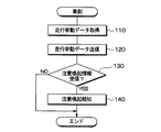
- each control unit 35 of the vehicle-mounted devices 3a to 3d executes the program recorded in the ROM, thereby repeatedly performing the process shown in FIG. .
- the described flowchart includes a plurality of sections (or referred to as S), and each section is expressed as S110, for example. Further, each section can be divided into a plurality of subsections, while a plurality of sections can be combined into one section.
- Each section can be referred to as a device or a unique name, for example, a detection section can be referred to as a detection device, a detector (detector).
- the section includes (i) not only a section of software combined with a hardware unit (eg, a computer) but also (ii) a section of hardware (eg, an integrated circuit, a wiring logic circuit) and related devices. It can be realized with or without the function.
- the hardware section can be included inside the microcomputer.
- the control unit 35 first acquires travel behavior data using the vehicle signal acquisition unit 34 in S110.
- the travel behavior data is data indicating the travel behavior of the vehicle on which the vehicle is mounted.
- the types of travel behavior data to be acquired include data such as the current location of the host vehicle, the steering angle of the steered wheels, and the vehicle speed, which are periodically transmitted from the ECU or the like to the in-vehicle LAN.
- the travel behavior data acquired by the control unit 35 in S110 of this time is the travel behavior data acquired by the vehicle signal acquisition unit 34 after executing S110 during the previous execution of FIG.
- the travel behavior data acquired in S110 immediately before is transmitted to the server 1 using the communication unit 32.
- the travel behavior data includes a vehicle ID for distinguishing a vehicle on which the vehicle is mounted from other vehicles, and information on an acquisition date and time when the travel behavior data is acquired.
- S130 after executing S130 during the previous execution of FIG. 3 and before the present time, it is determined whether or not new alert information is received from the server 1 via the communication unit 32, and it is determined that it has been received. If it is, the process proceeds to S130, and if it is determined that it has not been received, the process of FIG. In S140, the alerting unit 31 is used to perform alerting notification based on the newly received alerting information. After S140, the current process in FIG. 3 ends.
- the processing unit 13 always executes this reception recording process in parallel with other processes by executing a program recorded in the ROM or flash memory of the storage unit.
- the processing unit 13 first waits until receiving travel behavior data from any of the vehicle-mounted devices 3a to 3d in S170.
- the traveling behavior data is received from any of the on-vehicle devices 3a to 3d via the communication unit 11, the process proceeds to S180.
- the processing unit 13 of the server 1 receives one piece of driving behavior data from each of the vehicle-mounted devices 3a to 3d, the received driving behavior data is added to the driving history DB 12c. As a result, the past travel behavior data of the vehicles 2a to 2d is accumulated in the travel history DB 12c.
- the processing unit 13 executes the program recorded in the ROM or the flash memory of the storage unit, thereby performing this detection process in parallel with other processes in a repeated cycle (for example, periodically in a 1 second cycle). )Execute.
- the processing unit 13 of the travel behavior data recorded in the travel history DB 12c has an acquisition date and time within a range from a predetermined point in the past (for example, one minute before) to the present. Read driving behavior data.
- FIG. 6 shows details of the process of S220.
- the processing unit 13 executes a series of processes S221 to S227 once for each of the vehicles 2a to 2d.
- the processing unit 13 first includes, in S221, only all the travel behavior data including the vehicle ID of the vehicle among the travel behavior data read out in the immediately preceding S210. To extract.
- the acquisition date and location information is read from the travel behavior data extracted in the immediately preceding S221. Then, the day of the week and the time zone to which the read acquisition date belongs are specified, and further, the same geographical area as the read location is specified.
- the time zone classification is determined in advance. For example, 12 time zones may be determined in advance by dividing 24 hours that do not specify a day every 2 hours.
- the division of the geographic area is also determined in advance, and for example, the geographic area may be divided for each region having a length of 500 meters along the road. In many cases, a plurality of sets of one specified day of the week, one time zone, and one geographical area are specified.
- normal driving data corresponding to the specified day of the week, time zone, and geographic area is read from the normal driving DB 12a.
- the normal travel DB 12a has a plurality of normal travel data, and each normal travel data corresponds to one of a set of day of the week, time zone, and geographic area.
- Each normal driving data is data indicating the normal driving behavior of the vehicle in a set of day of the week, time zone, and geographical area corresponding to the normal driving data.
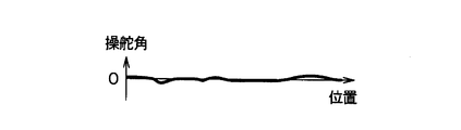
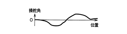
- the data of the steering angle for each position on the road is recorded so that the steering angle hardly changes with the position change on the road.
- vehicle speed data for each position on the road such that the vehicle speed decreases at a constant acceleration from a specific position on the road (for example, the position of the temporary stop line) at 100 meters and the vehicle speed becomes zero at the specific position. It is included.
- the avoidance action is an action in which the driver operates the vehicle to avoid an obstacle on or near the road.
- the steering angle for each position of the travel behavior data specified in S221 is compared with the steering angle for each position of the normal travel data extracted in S223 based on the travel behavior data.
- the difference between the steering angle indicated by the travel behavior data and the steering angle indicated by the normal travel data is calculated at each position on the road.
- a position where the steering angle difference is maximum and a position where the difference is within a predetermined distance is detected.
- the absolute value of the difference between the maximum value of the steering angle at the maximum position and the minimum value of the steering angle at the minimum position is calculated.
- the calculated absolute value is equal to or greater than the reference value, it is detected that the avoidance action of the vehicle has occurred at the midpoint position of the line segment connecting the position where the maximum value and the position where the value is minimum. If the calculated absolute value is not greater than or equal to the reference value, it is determined that the avoidance action of the vehicle has not occurred at the midpoint position.
- the generation position and generation date and time (corresponding to an example of the generation point) of the avoidance action detected in S225 are added to the avoidance action data in the RAM.
- the occurrence date and time is specified to be the location of the vehicle at the occurrence position based on the acquisition date and time in the travel behavior data of the vehicle in the vicinity of the occurrence position.
- the occurrence position and the occurrence date and time of the avoidance action that occurred in the vehicle are recorded in the avoidance action data for each vehicle.
- the generation position and the generation date and time of the avoidance action that occurred in the past in the vehicles 2a to 2d are sequentially added to the avoidance action data.
- S230 it is determined whether or not an avoidance action is detected in S220. If it is determined that the avoidance action is detected, the process proceeds to S240. If it is determined that the avoidance action is not detected, the detection process of FIG. To do.
- a set corresponding to the surrounding avoidance action is extracted from the set of the occurrence position and the occurrence date and time of the avoidance action included in the avoidance action data. Specifically, as illustrated in FIG. 9, the processing unit 13 first reads the set of the occurrence position and the occurrence date and time of the avoidance action recorded in the avoidance action data in the immediately preceding S220 in S243.
- the geographic area including the occurrence position read in immediately preceding S243 and the period including the occurrence date and time read in immediately preceding S243 are specified.
- the geographic area is assumed to be an area having a radius of 100 m or less centered on the occurrence position read out in the previous S243.
- the period shall be within 1 minute before and after the occurrence time.
- the occurrence position and the occurrence date and time of the avoidance action that has the occurrence position in the specified geographic area and has the occurrence date and time within the specified period correspond to the surrounding avoidance action. Extracted from avoidance behavior data as avoidance behavior.
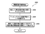
- FIG. 10 shows details of the processing of S250.
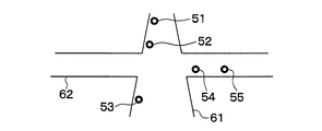
- the processing unit 13 maps the surrounding avoidance behavior extracted in the immediately preceding S240 (more specifically, S247) on the road map. Specifically, as shown in FIG. 11, which of the plurality of generation positions 51 to 55 of the extracted surrounding avoidance actions and which of the plurality of roads 61 and 62 belong to, and which of the destination roads to which the road belongs Determine if it is in position. Since the map DB 12d includes map data indicating the location ranges of a plurality of roads, the processing of S252 is realized by using this map data. In the example of FIG. 11, the road 61 and the road 62 are recorded as different roads that intersect each other in the map data.
- one is selected from the surrounding avoidance actions mapped on the map in the immediately preceding S252.
- the method of selecting may be random or a method of selecting the one with the earliest acquisition date. In the example of FIG. 12, the avoidance action 53 is selected.
- the related avoidance action group extracted in this way is likely to be a plurality of avoidance actions that are caused by different vehicles to avoid the same object at different positions at different times.
- vehicles 2b, 2c, and 2d are traveling on a road 61 in this order. Is walking on the road 61 so as to obstruct the car.
- the generation position 53 at the time of occurrence of the avoidance action is the same as the position of the person 70 at that time.
- the occurrence position 52 at the time of occurrence of the avoidance action is the same as the position of the person 70 at that time. Is moved from the position 53 with the movement of.
- the generation position 51 at the time of the occurrence of the avoidance action is the same as the position of the person 70 at that time. Is moved from the position 52 with the movement of.
- the same object 70 that has caused the related avoidance action group 50 is a moving object to be watched. Specifically, the moving speed of the same object 70 is calculated based on all occurrence positions and occurrence dates and times belonging to the related avoidance action group 50. Then, it is determined whether or not the calculated moving speed is within a reference range (for example, 2 km / h or more and less than 40 km / h). If it is within the reference speed range, it is determined that the object is a moving caution object, and the process proceeds to S270. If it is outside the reference speed range, it is determined that the object is not a moving caution object, and the current detection process is terminated.
- a reference range for example, 2 km / h or more and less than 40 km / h.
- the moving speed of the same object 70 can be grasped.
- the generation point of the avoidance action 53 is T53
- the generation position is P53
- the generation point of the avoidance action 53 is T52
- the generation position is P52
- the avoidance action When the occurrence time of 51 is T51 and the occurrence position is P51, the moving speed is calculated by ⁇ L (P52, P53) / (T52 ⁇ T53) + L (P51, P52) / (T51 ⁇ T52) ⁇ / 2.
- L (P52, P53) is a straight line distance (or distance along the road) from the generation positions P52 to P53
- L (P51, P52) is a straight line distance (or along the road) from the generation positions P51 to P52. Distance).
- the processing unit 13 first identifies the type of the attention object 70 based on the moving speed of the object 70 determined to be the attention object in S260. For example, if the moving speed is 2 km / h or more and less than 10 km / h, it is determined that the attention object 70 is a person, and if the moving speed is 10 km / h or more, it is determined that the attention object 70 is a bicycle.
- the processing unit 13 specifies the moving direction of the attention object 70 on the road 61.
- the direction from the position of the first avoidance action caused by the attention object 70 to the position of the last avoidance action is the movement direction of the attention object 70 on the road 61. To do.
- the position and date and time of occurrence of the last avoidance action caused by the attention object 70, the moving speed of the attention object 70, the moving direction on the road 61, and the attention is additionally recorded in the attention object DB 12b as one attention object data.
- the information of the moving attention object 70 is accumulated in the attention object DB 12b of the server 1.
- the processing unit 13 executes the program recorded in the ROM or the flash memory of the storage unit, thereby performing this detection process in parallel with other processes in a repeated cycle (for example, periodically in a 1 second cycle). ) Run for each vehicle.
- the alert output process for the vehicle 2a (corresponding to an example of another vehicle) will be described.
- the alert process for the other vehicles 2b to 2d also excludes the value of the vehicle ID. It is the same.
- the processing unit 13 reads, from the travel history DB 12c, the travel behavior data including the vehicle ID of the vehicle 2a that has an acquisition date and time within the past one minute.
- the route after the present time of the vehicle 2a is predicted based on the information on the location of the vehicle 2a included in the traveling behavior data read out in the immediately preceding S310.
- the predicted course data includes a plurality of future times and the predicted position of the vehicle 2a at each of these times.
- a well-known technique may be used as a method for predicting a future course based on past driving behavior data.
- the course may be predicted on the assumption that the road on which the vehicle 2a is currently traveling travels along the road at an average speed of the past minute.
- the attention object data recorded in the attention object DB 12b is read.
- the moving speed of the attention object 70 Based on the moving direction on the road 61, the course of each attention object is predicted. For example, the route is predicted on the assumption that the attention object moves in the movement direction at the movement speed along the road to which the last occurrence position of the avoidance action belongs.
- the communication unit 11 is used to transmit alert information based on the information on the target object that needs to be avoided to the server 1.
- the attention object information that needs to be avoided is the attention object data of the attention object that is determined to be overtaken by the vehicle 2a in S340. After S350, the current alert output process is terminated.
- the control unit 35 when the control unit 35 receives the alerting information via the communication unit 32, it has received the alerting information in S130 of the process illustrated in FIG. It judges and progresses to S140 and performs alerting alerting in S140.
- the content included in the received alerting information is notified to the driver of the vehicle 2a using the image display device and the audio output device of the notification unit 31.
- the information to be notified is, for example, the current position of the alerting target object, the moving direction, the moving speed, the point where the vehicle is scheduled to pass the alerting target object, and the time.
- the server 1 is configured such that the traveling behavior of the vehicle on which the vehicle-mounted device is mounted from each of the plurality of vehicle-mounted devices 3a, 3b, 3c, and 3d mounted on the plurality of vehicles 2a, 2b, 2c, and 2d. Is received and recorded in the travel history DB 12c.
- the server 1 reads travel behavior data indicating the travel behavior of the vehicle from the travel history DB 12c, and the avoidance behavior generated in the vehicle based on the read travel behavior data. Try to detect.
- the server 1 selects a group of related avoidance actions that are a plurality of avoidance actions that have occurred in different vehicles at different positions at different times due to the same object among the avoidance actions for each of the plurality of vehicles 2a to 2d that have been successfully detected. Are extracted based on the occurrence position and the occurrence time of the avoidance action detected.
- the server 1 records information indicating the change in position of the same object that causes the extracted related avoidance action group in the attention object DB 12b as attention object data indicating the position change of the attention object.
- the server 1 records a group of related avoidance actions that are a plurality of avoidance actions that have occurred at different times at different positions due to the same object in the attention target database as information indicating the position change of the same object. In this way, one moving object can be recorded as one attention object.
- the server 1 predicts the course of the other vehicle 2a based on the data indicating the traveling behavior of the other vehicle 2a other than the plurality of vehicles 2b, 2c, and 2d, and based on the predicted course and the attention object data. Thus, it is determined whether or not the other vehicle 2a needs to avoid the attention object. And the server 1 transmits the alerting information based on the information of the attention object which needs to be avoided to the other vehicle 2a based on the determination that the other vehicle 2a needs to avoid the attention object. By doing in this way, one moving object can be notified to the vehicle not as a plurality of attention objects but as one attention object.
- the server 1 selects a group of avoidance actions that occur within a predetermined time range and a predetermined position range and are on the same road among the detected avoidance actions for each of the plurality of vehicles. Extract as a group. In this way, the related avoidance action group can be extracted with higher accuracy.
- the server 1 reads normal driving data indicating the normal driving behavior of the vehicle from the normal driving database 12a, and compares the read normal driving data with the driving behavior of the vehicle, thereby avoiding the avoidance behavior generated in the vehicle. Is detected. By doing in this way, avoidance action can be detected with higher accuracy compared to the case where normal running data is not used.
- the control unit 35 of the vehicle-mounted devices 3a to 3d executes the process of FIG. 18 in parallel with the process of FIG.
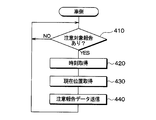
- the control unit 35 first determines whether or not a caution target report has newly occurred in S410, and repeats the determination process of S410 until it is determined that it has occurred.
- the attention object report is a predetermined input action performed in order for the driver of the vehicle on which the vehicle-mounted device is mounted to intentionally notify the moving attention object. For example, the act of operating a predetermined report switch among the steering switches of the input unit 33 corresponds to the caution target report. In addition, the action of uttering the word “moving object discovery” so as to be input to the input unit 33 corresponds to the attention object report.
- the process proceeds to S420, where the current time is acquired, and then, in S430, the current position of the vehicle on which the vehicle-mounted device is mounted is acquired via the vehicle signal acquisition unit 34. This current position is a position near the moving object.
- the caution report data is transmitted to the server 1 using the communication unit 32.
- This attention report data includes the current time acquired in S420 and the current position acquired in S430. After S440, the process returns to S410 again.
- each of the vehicle-mounted devices 3a to 3d performs a caution report based on the fact that the driver of the installation destination has performed an input act to intentionally notify the moving caution object. Data is transmitted to the server 1.
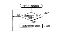
- the processing unit 13 repeats the determination processing of S510 until it is determined that the attention report data is newly received in S510 of the report reception processing shown in FIG. If the processing unit 13 determines that the attention report data has been newly received, the processing unit 13 proceeds to S520 and records the attention object data in the attention object DB 12b indicating the position change of the attention object based on the content of the received attention report data. .
- the data of the target object recorded in S520 has the same data format as the target object data recorded in S270 of FIG. More specifically, in S520, the processing unit 13 adopts the current position and the current time included in the attention report data received in S510, respectively, as the generation position and the generation date and time of the avoidance action of the attention target data to be recorded. In addition, a fixed value (for example, 1 km / h and the north side along the road) determined in advance is adopted as the moving speed of the attention object and the moving direction on the road. A predetermined fixed value (for example, a person) is also used as the type of the attention object. The attention object data recorded in this way is used similarly without being distinguished from the attention object data recorded in S270 of FIG.
- a fixed value for example, 1 km / h and the north side along the road
- the server 1 receives the caution report data including the position and time information from any of the plurality of vehicles, and indicates the caution object indicating the position change of the caution object based on the received caution report data. Data is recorded in the attention object DB 12b. In this way, it is possible to record one moving object as one attention object in a more direct procedure.
- the processing unit 13 of the server 1 functions as an example of the reception recording unit or the reception recording device by executing S170 and S180, and the avoidance detection unit or the avoidance detector by executing S220. It serves as an example.
- the processing unit 13 functions as an example of an extraction unit or an extractor by executing S250, and functions as an example of an attention target recording unit or an attention target recording device by executing S270 and S520.
- the processing unit 13 functions as an example of a determination unit or a determination unit by executing S320, S330, and S340, and functions as an example of a transmission unit or a transmitter by executing S350.
- the elements constituting the embodiment are not necessarily essential unless explicitly stated as essential and clearly considered essential in principle.
- numerical values such as the number, numerical value, quantity, range, etc. of the constituent elements of the embodiment are mentioned, it is clearly limited to a specific number when clearly indicated as essential and in principle. The number is not limited to the specific number except for the case.
- a plurality of values are exemplified for a certain amount, it is also possible to adopt a value between the plurality of values unless specifically stated otherwise and in principle impossible.
- the storage medium or memory is a non-temporary tangible recording medium.
- Module 1 In each said embodiment, although the alerting output apparatus was implement
- Module 2 In the above embodiment, four sets of the vehicle and the vehicle-mounted device are illustrated, but the number of the vehicle and the vehicle-mounted device configuring the alerting system may be five or more.
Abstract
複数の車両(2a、2b、2c、2d)にそれぞれ搭載された複数の車載器(3a、3b、3c、3d)の各々から、当該車載器の搭載先の車両の走行挙動を示す走行挙動データを受信して走行履歴データベース(12c)に記録する。複数の車両の各々について、当該車両の走行挙動を示す走行挙動データを走行履歴データベースから読み出し、読み出した当該走行挙動データに基づいて、当該車両に発生した回避行動を検出する。検出した複数の車両毎の回避行動のうち、同一物に起因して異なる位置で異なる時点に異なる対象車両(2b、2c、2d)で発生した複数の回避行動である関連回避行動群を、検出された回避行動の発生位置および発生時点に基づいて抽出する。抽出した関連回避行動群の原因となる同一物の位置変化を示す情報を、注意対象物の位置変化を示す注意対象データとして記録する。
Description
本出願は、2015年6月22日に出願された日本出願番号2015-124609号に基づくもので、ここにその記載内容を援用する。
本開示は、注意喚起出力装置に関するものである。
特許文献1には、複数車両の実際の走行実績データを分析することで危険地点を予測し、各利用者へ注意情報を送信する注意喚起装置が開示されている。この注意喚起装置は、走行実績データに基づいて判定対象地点が危険地点か否かを判定し、危険と判定した地点を危険地点として登録し、車両が危険地点の直前を走行している場合に注意情報を送信する。この注意喚起装置は、判定対象地点を緯度、経度が固定された地点として扱っている。
しかし、発明者の検討によれば、ドライバにとって注意すべき対象は固定地点だけではなく、移動している物体も注意対象物とすることが望ましい。
本開示は、移動している1つの物体を1つの注意対象物として記録することを目的とする。
上記目的を達成するための本開示の一つの観点によれば、注意喚起装置は、次のように、受信記録部、回避検出部、抽出部、記録部を備えるように提供される。受信記録部は、複数の車両にそれぞれ搭載された複数の車載器の各々から、当該車載器の搭載先の車両の走行挙動を示す走行挙動データを受信して走行履歴データベースに記録する。回避検出部は、複数の車両の各々について、当該車両の走行挙動を示す走行挙動データを走行履歴データベースから読み出し、読み出した当該走行挙動データに基づいて、当該車両に発生した回避行動の検出を試みる。抽出部は、回避検出部が検出した複数の車両毎の回避行動のうち、同一物に起因して異なる位置で異なる時点に、複数の車両のうちの、複数の異なる車両である対象車両のそれぞれで発生した複数の回避行動である関連回避行動群を、回避検出部が検出した複数の対象車両毎の回避行動の発生位置および発生時点に基づいて抽出する。記録部は、抽出部が抽出した関連回避行動群の原因となる同一物の位置変化を示す情報を、注意対象物の位置変化を示す注意対象データとして注意対象データベースに記録する。
このように、注意喚起出力装置は、同一物に起因して異なる位置で異なる時点に発生した複数の回避行動である関連回避行動群を、同一物の位置変化を示す情報として注意対象データベースに記録する。このようにすることで、移動している1つの物体を1つの注意対象物として記録することができる。
本開示についての上記目的およびその他の目的、特徴や利点は、添付の図面を参照しながら下記の詳細な記述により、より明確になる。
第1実施形態における注意喚起システムの全体構成図である。
車載器の構成図である。
車載器の制御部が実行する処理のフローチャートである。
サーバが実行する受信記録処理のフローチャートである。
サーバが実行する検出処理のフローチャートである。
図5のS220の処理の詳細を示すフローチャートである。
通常走行データの内容を例示する図である。
収集データの内容を例示する図である。
図5のS240の処理の詳細を示すフローチャートである。
図5のS250の処理の詳細を示すフローチャートである。
同一物に起因する回避行動群の抽出方法の一工程を示す図である。
同一物に起因する回避行動群の抽出方法の一工程を示す図である。
同一物に起因する回避行動群の抽出方法の一工程を示す図である。
車両が人を回避した後の状況を示す図である。
車両が人を回避した後の状況を示す図である。
車両が人を回避した後の状況を示す図である。
サーバが実行する注意喚起出力処理のフローチャートである。
第2実施形態において車載器が実行する処理のフローチャートである。
サーバが実行する報告受信処理のフローチャートである。
(第1実施形態)
以下、本開示の第1実施形態について説明する。図1に示すように、本実施形態の注意喚起システムは、サーバ1および複数個の車載器3a、3b、3c、3dを備えている。車載器3a、3b、3c、3dは、それぞれ、車両2a、2b、2c、2dに、搭載されている。これらの車両は、搭載車両あるいはホスト車両とも言及される。サーバ1は、通信ネットワーク4(例えばインターネット)および無線基地局5a、5bを介して、車載器3a~3dと通信可能になっている。
以下、本開示の第1実施形態について説明する。図1に示すように、本実施形態の注意喚起システムは、サーバ1および複数個の車載器3a、3b、3c、3dを備えている。車載器3a、3b、3c、3dは、それぞれ、車両2a、2b、2c、2dに、搭載されている。これらの車両は、搭載車両あるいはホスト車両とも言及される。サーバ1は、通信ネットワーク4(例えばインターネット)および無線基地局5a、5bを介して、車載器3a~3dと通信可能になっている。
サーバ1は、注意喚起装置の一例に相当し、通信部11、記憶部12、処理部13を備えている。通信部11は、通信ネットワーク4に接続するための周知の通信インターフェースである。
記憶部12は、各種データを記録するための記憶媒体であり、RAM、ROM、および、書き込み可能な不揮発性記憶媒体(例えばフラッシュメモリ)を含んでいる。また、書き込み可能な不揮発性記憶媒体は、通常走行DB12a、注意対象DB12b、走行履歴DB12c、地図DB12dを含んでいる。DBはデータベースの略である。本実施形態では、通常走行DB12a、注意対象DB12b、走行履歴DB12c、地図DB12dは、書き込み可能な不揮発性記憶媒体の一部の記憶領域である。処理部13は、各種演算、制御処理を実行するCPUである。
図2に示すように、車載器3a~3dは、それぞれ同じ構成を有している。具体的には、車載器3a~3dの各々は、報知部31、通信部32、入力部33、車両信号取得部34、制御部35を有している。
報知部31は、搭載先の車両のドライバが見えるように画像を表示する画像表示装置、および、搭載先の車両のドライバに聞こえるように音声を出力する音声出力装置を有している。
通信部32は、基地局5a、5bのいずれかに無線接続するための周知の無線通信インターフェースである。入力部33は、搭載先の車両のドライバの入力行為(例えば、スイッチ操作入力、音声入力)を受け付ける部材(例えば、ステアリングスイッチ、音声入力装置)である。
車両信号取得部34は、搭載先の車両の車内LANに接続される他の車載機器から車両の走行挙動に関する情報を取得する装置である。他の車載機器としては、例えば、GPS受信機を利用して搭載先の車両の現在の所在位置の緯度、経度を特定するECU(例えばナビゲーションECU)がある。また、他の車載機器としては、車速センサ、加速度センサ、舵角センサから検出信号が入力され、それらセンサからの検出信号に基づいて、搭載先の車両の車速、操舵輪の操舵角等を特定するECU(例えばボディECU)等がある。尚、情報は、不可算名詞のみならず、可算名詞としても使用される。複数の情報は、複数の情報項目と同等である。また、データは、単数形あるいは、複数形としても使用され、よって、データは、一つのデータ項目、あるいは、複数のデータ項目と同等として、使用される。
制御部35は、電子制御ユニット、コントローラとも言及される。本実施形態では、一例として、制御部35は、CPU、RAM、ROM等を備え、CPUがROMに記録されたプログラムを実行し、その実行の際にRAMをワークメモリとして利用する。以下、CPUが実行する処理を制御部35が実行する処理とみなして説明する。尚、制御部35は、各々の処理の一部あるいは全てを、ハードウエア回路で実現してもよい。
次に、上記のように構成された注意喚起システムの作動について説明する。まず、車載器3a~3dの各々の制御部35は、ROMに記録されたプログラムを実行することで、図3に示す処理を、繰り返し周期的に(例えば1秒周期で定期的に)実行する。
記載されるフローチャートは、複数のセクション(あるいはSと言及される)を含み、各セクションは、たとえば、S110と表現される。さらに、各セクションは、複数のサブセクションに分割されることができる、一方、複数のセクションが合わさって一つのセクションにすることも可能である。各セクションは、デバイス、あるいは、固有名として、例えば、検出セクションは、検出デバイス、検出器(ディテクタ)として、言及されることができる。また、セクションは、(i)ハードウエアユニット(例えば、コンピュータ)と組み合わさったソフトウエアのセクションのみならず、(ii)ハードウエア(例えば、集積回路、配線論理回路)のセクションとして、関連する装置の機能を含みあるいは含まずに実現できる。さらに、ハードウエアのセクションは、マイクロコンピュータの内部に含まれることもできる。
この図3の処理において制御部35は、まずS110で、車両信号取得部34を用いて、走行挙動データを取得する。走行挙動データは、搭載先の車両の走行挙動を示すデータである。取得する走行挙動データの種類としては、上述したECU等から車内LANに定期的に送信される自車両の現在の所在位置、操舵輪の操舵角、車速等のデータがある。また、今回のS110で制御部35が取得する走行挙動データは、前回の図3の実行時にS110を実行した後かつ現在以前に車両信号取得部34が取得した走行挙動データである。
続いてS120では、通信部32を用いて、直前のS110で取得した走行挙動データを、サーバ1に送信する。ただし、この走行挙動データには、自機が搭載される車両を他の車両と区別するための車両IDと、当該走行挙動データが取得された日時である取得日時の情報も含める。
続いてS130では、前回の図3の実行時にS130を実行した後かつ現在以前に、通信部32を介してサーバ1から新たに注意喚起情報を受信したか否かを判定し、受信したと判定すればS130に進み、受信していないと判定すれば今回の図3の処理を終了する。S140では、報知部31を用いて、当該新たに受信した注意喚起情報に基づいた注意喚起報知を行う。S140の後、今回の図3の処理が終了する。
次に、サーバ1の処理部13が実行する受信記録処理について、図4を用いて説明する。処理部13は、記憶部のROMまたはフラッシュメモリに記録されたプログラムを実行することで、この受信記録処理を、他の処理と同時並列的に、常時実行している。
処理部13は、この受信記録処理において、まずS170で、車載器3a~3dのいずれかから走行挙動データを受信するまで待つ。そして、通信部11を介して車載器3a~3dのいずれかから走行挙動データを受信すると、S180に進む。
S180では、直前のS180で受信した走行挙動データを走行履歴DB12cに記録する。S180の後は、S170に戻り、再度走行挙動データ
を受信するまで待つ。
を受信するまで待つ。
このような作動により、サーバ1の処理部13は、車載器3a~3dの各々から走行挙動データを1つ受信する度に、受信した当該走行挙動データを走行履歴DB12cに追記していく。これによって、走行履歴DB12cには、過去の車両2a~2dの走行挙動データが蓄積されていく。
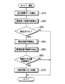
次に、サーバ1の処理部13が実行する検出処理について、図5を用いて説明する。処理部13は、記憶部のROMまたはフラッシュメモリに記録されたプログラムを実行することで、この検出処理を、他の処理と同時並列的に、繰り返し周期的に(例えば1秒周期で定期的に)実行する。
処理部13は、この検出処理において、まずS210で、走行履歴DB12cに記録された走行挙動データのうち、取得日時が過去の所定時点(例えば1分前)から現在までの範囲内となっている走行挙動データを読み出す。
続いてS220では、車両毎に回避行動検出を行う。図6に、S220の処理の詳細を示す。図6に示すように、処理部13は、S220では、車両2a~2dの各々について、S221~S227の一連の処理を1回ずつ実行する。
処理部13は、或る車両を対象とするS221~S227の一連の処理において、まずS221では、直前のS210で読み出した走行挙動データのうち、当該車両の車両IDを含むすべての走行挙動データのみを抽出する。
続いてS223では、直前のS221で抽出した走行挙動データから、取得日時、および所在位置の情報を読み出す。そして、読み出した取得日時の属する曜日と時間帯を特定し、更に、読み出した所在位置と同じ地理エリアを特定する。
時間帯の区分は、あらかじめ決められており、例えば、日を特定しない24時間を2時間毎に区分けすることで12個の時間帯があらかじめ決められていてもよい。地理エリアの区分も、あらかじめ決められており、例えば、道路に沿った500メートルの長さの領域毎に地理エリアが区分けされていてもよい。多くの場合、特定された1つの曜日、1つの時間帯、1つの地理エリアの組が、複数組特定される。
更にS223では、特定した曜日、時間帯、地理エリアの組に対応する通常走行データを通常走行DB12aから読み出す。通常走行DB12aは、複数個の通常走行データを有し、個々の通常走行データは、曜日、時間帯、地理エリアの組の1つに対応する。そして、各通常走行データは、当該通常走行データに対応する曜日、時間帯、地理エリアの組における車両の通常の走行挙動を示すデータである。
例えば、或る直線道路の通常走行データでは、図7に示すように、道路上の位置変化と共に操舵角が殆ど変化しないような、道路上の位置毎の操舵角のデータが記録されている。あるいは、道路上の特定位置(例えば一時停止線の位置)の手間100メートルの位置から車速が一定加速度で低下して当該特定位置で車速がゼロになるような、道路上の位置毎の車速データが含まれている。
続いてS225では、S221で抽出した走行挙動データおよびS223で取得した通常走行データを比較することで、当該車両に発生した回避行動の検出を試みる。回避行動とは、道路上または道路近傍の障害物を避けるためにドライバが車両を操作する行為をいう。
例えば、S221で特定した走行挙動データの位置毎の操舵角(図8参照)と、当該走行挙動データに基づいてS223で抽出された通常走行データの位置毎の操舵角を比較する場合について説明する。この場合、道路上の各位置において、走行挙動データ示す操舵角と通常走行データの示す操舵角の差を算出する。そして、操舵角差が所定距離以内(例えば100メートル以内)の間隔で極大となっている位置と極小となっている位置を検出する。そして、その極大となる位置における操舵角の極大値とその極小となる位置における操舵角の極小値の差の絶対値を算出する。そして、算出した絶対値が基準値以上であれば、その極大となる位置と極小となる位置を繋ぐ線分の中点の位置において、当該車両の回避行動が発生したことを検出する。そして、算出した絶対値が基準値以上でなければ、当該中点の位置において車両の回避行動が発生していないと判定する。
回避行動を検出した場合、S227に進むが、走行挙動データの示すどの位置でも回避行動が検出できなかった場合は、S227をバイパスして、当該車両についてのS221~S227の一連の処理を終了する。
S227では、S225で検出した回避行動の発生位置および発生日時(発生時点の一例に相当する)をRAMの回避行動データに追加する。発生日時は、発生位置の近傍における当該車両の走行挙動データ中の取得日時に基づいて、当該発生位置における当該車両の所在位置となるよう、特定する。S227の後、当該車両についてのS221~S227の一連の処理を終了する。
このように、S220では、車両毎に、当該車両において発生した回避行動の発生位置および発生日時が、回避行動データに記録される。これにより、回避行動データには、車両2a~2dにおいて過去に発生した回避行動の発生位置および発生日時が逐次追加されていく。
続いてS230では、S220において回避行動が検出されたか否かを判定し、検出されていると判定した場合はS240に進み、検出されていないと判定した場合は今回の図3の検出処理を終了する。
S240では、回避行動データに含まれる回避行動の発生位置および発生日時の組のうち、周辺回避行動に該当する組を抽出する。具体的には、処理部13は、図9に示すように、まずS243で、直前のS220で回避行動データに記録された回避行動の発生位置および発生日時の組を読み出す。
続いてS247では、直前のS243で読み出した発生位置を含む地理エリアと、直前のS243で読み出した発生日時を含む期間を特定する。地理エリアは、直前のS243で読み出した発生位置を中心とする半径100m以内のエリアとする。期間は、発生時間の前後1分以内の期間とする。そして更に、S243で読み出した回避行動以外で、特定した地理エリア内に発生位置があり、かつ、特定した期間内に発生日時がある回避行動の発生位置および発生日時を、周辺回避行動に該当する回避行動として回避行動データから抽出する。S247の後、S240の処理が終了する。
S240に続いては、S250で、関連回避行動群を抽出する。図10に、S250の処理の詳細を示す。処理部13は、まずS252において、直前のS240(より具体的にはS247)で抽出した周辺回避行動を、道路地図上にマッピングする。具体的には、図11に示されるように、抽出された周辺回避行動の複数の発生位置51~55、複数の道路61、62のうちどの道路に属するのか、および、属する先の道路のどの位置にあるのか、を特定する。地図DB12dには、複数の道路の所在範囲を示す地図データが含まれているので、この地図データを用いることで、S252の処理が実現する。なお、図11の例では、道路61と道路62は、地図データにおいて互いに交差している別の道路として記録されている。
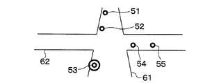
続いてS254では、直前のS252で地図上にマッピングされた周辺回避行動から1つを選択する。選択する方法は、ランダムでもよいし、取得日時が最も早いものを選択する方法でもよい。図12の例では、回避行動53が選択されている。
続いてS256では、直前のS254で選択した回避行動が属する道路と同じ道路上に存在するすべての回避行動を関連回避行動群として抽出する。図13の例では、回避行動51~55のうち、回避行動51、52が、選択された回避行動53と同じ道路61に属するので、回避行動51、52、53を関連回避行動群50として抽出する。S256の後、S250の処理が終了する。
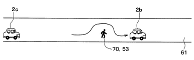
このようにして抽出された関連回避行動群は、同一物に起因して異なる位置で異なる時点に異なる車両が当該同一物を避けるために発生した複数の回避行動である可能性が高い。例えば、図14、図15、図16に示すように、車両2b、2c、2d(複数の対象車両の一例に相当する)がこの順に道路61を走行しており、更に、人70(同一物の一例に相当する)が道路61上を車に邪魔になるように歩いていたとする。
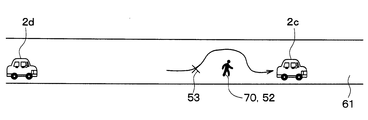
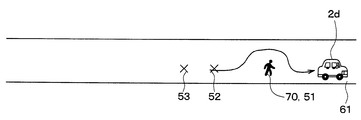
この場合、図14に示すように、まず車両2bが人70を回避して追い越した場合、その回避行動の発生時点における発生位置53は、その時の人70の位置と同じである。その後、図15に示すように、次に車両2cが人70を回避して追い越した場合、その回避行動の発生時点における発生位置52は、その時の人70の位置と同じであるから、人70の移動に伴って、位置53から移動している。その後、図16に示すように、次に車両2dが人70を回避して追い越した場合、その回避行動の発生時点における発生位置51は、その時の人70の位置と同じであるから、人70の移動に伴って、位置52から移動している。このように、人70に起因して、異なる時間に異なる位置で異なる車両において回避行動が発生する。
S250に続いては、S260で、関連回避行動群50の起因となった上記同一物70が、移動する注意対象物であるか否かを判定する。具体的には、関連回避行動群50に属するすべての発生位置および発生日時に基づいて、当該同一物70の移動速度を算出する。そして、算出した移動速度が基準範囲(例えば、時速2km以上時速40km未満)以内にあるか否かを判定する。そして、基準速度範囲内にあれば移動する注意対象物であると判定してS270に進み、基準速度範囲外にあれば移動する注意対象物でないと判定して今回の検出処理を終了する。
このように抽出された関連回避行動群があれば、同一物70の移動速度を把握することが可能となる。同一物70の移動速度については、例えば、図11~図16の例において、回避行動53の発生時点がT53、発生位置がP53、回避行動53の発生時点がT52、発生位置がP52、回避行動51の発生時点がT51、発生位置がP51の場合、移動速度は、{L(P52,P53)/(T52-T53)+L(P51,P52)/(T51-T52)}/2で算出する。ここで、L(P52,P53)は発生位置P52からP53までの直線距離(または道路に沿った距離)、L(P51,P52)は発生位置P51からP52までの直線距離(または道路に沿った距離)である。
S270では、S260で移動する注意対象物であると判定した物(すなわち、関連回避行動群の原因となる同一物70)の位置変化を示す情報を、注意対象物の位置変化を示す注意対象データとして、注意対象DB12bに記録する。
より具体的には、処理部13は、S270では、まず、S260で注意対象物であると判定した物70の移動速度に基づいて、当該注意対象物70の種別を特定する。例えば、移動速度が時速2km以上10km未満であれば注意対象物70が人であると判定し、移動速度が時速10km以上であれば注意対象物70が自転車であると判定する。
また処理部13は、注意対象物70の道路61上の移動方向を特定する。例えば、関連回避行動群のうち、この注意対象物70に起因して発生した最初の回避行動の位置から最後の回避行動の位置への方向を、注意対象物70の道路61上の移動方向とする。
そして、関連回避行動群のうち、この注意対象物70に起因して発生した最後の回避行動の発生位置および発生日時、この注意対象物70の移動速度および道路61上の移動方向、並びに、注意対象物70の種別を、1つの注意対象データとして、注意対象DB12bに追加記録する。S270の後、今回の検出処理が終了する。
このようにすることで、サーバ1の注意対象DB12bには、移動する注意対象物70の情報が蓄積されていく。
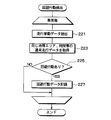
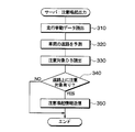
次に、サーバ1の処理部13が実行する注意喚起出力処理について、図17を用いて説明する。処理部13は、記憶部のROMまたはフラッシュメモリに記録されたプログラムを実行することで、この検出処理を、他の処理と同時並列的に、繰り返し周期的に(例えば1秒周期で定期的に)、車両毎に実行する。
ここでは、車両2a(他車両の一例に相当する)を対象とする注意喚起出力処理について説明するが、他の車両2b~2dを対象とする注意喚起処理についても、車両IDの値を除いて同様である。
処理部13は、まずS310では、走行履歴DB12cから、車両2aの車両IDが含まれた走行挙動データのうち、取得日時が過去1分以内となっているものを読み出す。
続いてS320において、直前のS310で読み出した走行挙動データに含まれる車両2aの所在位置の情報に基づいて、車両2aの現在以降の進路を予測する。予測された進路のデータは、複数の未来の時刻と、それら時刻の各々における車両2aの予想位置とを含む。過去の走行挙動データに基づいて未来の進路を予測する方法としては、周知の技術を用いればよい。例えば、車両2aが現在走行している道路を、過去1分の平均速度で、道なりに、走行すると仮定して、進路を予測してもよい。続いてS330では、注意対象DB12bに記録された注意対象データを読み出す。
続いてS340では、S320で予測した車両2aの進路上において、注意対象DB12bに記録された注意対象物を回避する必要が生じるか否かを判定する。
具体的には、まず、注意対象DB12b中の注意対象データに基づいて、すなわち、当該注意対象物に起因して発生した最後の回避行動の発生位置および発生日時、この注意対象物70の移動速度および道路61上の移動方向に基づいて、各注意対象物の進路を予想する。例えば、当該注意対象物が、最後の回避行動の発生位置が属する道路を、当該移動速度で、当該移動方向に、移動すると仮定して、進路を予測する。
続いて、車両2aの進路と、各注意対象物について予測した進路に基づいて、車両2aが各注意対象物を追い越すか否かを判定する。
追い越すと判定された注意対象物が1つ以上ある場合、車両2aの進路上において、注意対象DB12bに記録された注意対象物を回避する必要が生じると判定し、S350に進む。追い越すと判定された注意対象物が1つもない場合、車両2aの進路上において、注意対象DB12bに記録された注意対象物を回避する必要が生じないと判定し、S350をバイパスして今回の注意喚起出力処理を終了する。
S350では、通信部11を用いて、回避する必要が生じる注意対象物の情報に基づく注意喚起情報を、サーバ1に送信する。回避する必要が生じる注意対象物の情報とは、S340で車両2aが追い越すと判定した注意対象物の注意対象データである。S350の後、今回の注意喚起出力処理を終了する。
すると、車両2aに搭載される車載器3aにおいて、制御部35は、通信部32を介して当該注意喚起情報を受信すると、既に説明した図3の処理のS130において、注意喚起情報を受信したと判定してS140に進み、S140で注意喚起報知を行う。注意喚起報知では、報知部31の画像表示装置および音声出力装置を用いて、受信した注意喚起情報に含まれる内容を車両2aのドライバに報知する。報知する内容は、例えば、注意喚起対象物の現在位置、移動方向、移動速度、車両が当該注意喚起対象物を追い越す予定の地点、時刻である。
以上説明した通り、サーバ1は、複数の車両2a、2b、2c、2dにそれぞれ搭載された複数の車載器3a、3b、3c、3dの各々から、当該車載器の搭載先の車両の走行挙動を示す走行挙動データを受信して走行履歴DB12cに記録する。
そしてサーバ1は、それら複数の車両2a~2dの各々について、当該車両の走行挙動を示す走行挙動データを走行履歴DB12cから読み出し、読み出した当該走行挙動データに基づいて、当該車両に発生した回避行動の検出を試みる。
更にサーバ1は、検出に成功した複数の車両2a~2d毎の回避行動のうち、同一物に起因して異なる位置で異なる時点に異なる車両で発生した複数の回避行動である関連回避行動群を、が検出した回避行動の発生位置および発生時点に基づいて抽出する。
更にサーバ1は、抽出した関連回避行動群の原因となる上記同一物の位置変化を示す情報を、注意対象物の位置変化を示す注意対象データとして注意対象DB12bに記録する。
このように、サーバ1は、同一物に起因して異なる位置で異なる時点に発生した複数の回避行動である関連回避行動群を、同一物の位置変化を示す情報として注意対象データベースに記録する。このようにすることで、移動している1つの物体を1つの注意対象物として記録することができる。
また、サーバ1は、複数の車両2b、2c、2d以外の他車両2aの走行挙動を示すデータに基づいて、当該他車両2aの進路を予測し、予測した進路と上記注意対象データとに基づいて、他車両2aが注意対象物を回避する必要が生じるか否かを判定する。そしてサーバ1は、他車両2aが注意対象物を回避する必要が生じると判定したことに基づいて、回避する必要が生じる注意対象物の情報に基づく注意喚起情報を他車両2aに送信する。このようにすることで、移動している1つの物体を複数の注意対象物ではなく1つの注意対象物として車両に通知することができる。
また、サーバ1は、検出した複数の車両毎の回避行動のうち、所定の時間範囲および所定の位置範囲内で発生した回避行動であってかつ同じ道路上にある回避行動群を、関連回避行動群として抽出する。このようにすることで、より高い正確性で関連回避行動群を抽出することができる。
また、サーバ1は、車両の通常の走行挙動を示す通常走行データを通常走行データベース12aから読み出し、読み出した通常走行データと当該車両の走行挙動とを比較することで、当該車両に発生した回避行動を検出する。このようにすることで、通常走行データを用いない場合に比べ、より高い正確性で回避行動を検出することができる。
(第2実施形態)
次に、本開示の第2実施形態について説明する。本実施形態の注意喚起システムは、第1実施形態の注意喚起システムに対して、車載器3a~3dの制御部35が、図3の処理に加え図18の処理を実行し、かつ、サーバ1の処理部13が更に図19の報告受信処理を実行するよう、変更されている。他の構成および作動は、第1実施形態と同じである。
次に、本開示の第2実施形態について説明する。本実施形態の注意喚起システムは、第1実施形態の注意喚起システムに対して、車載器3a~3dの制御部35が、図3の処理に加え図18の処理を実行し、かつ、サーバ1の処理部13が更に図19の報告受信処理を実行するよう、変更されている。他の構成および作動は、第1実施形態と同じである。
まず、図18の処理について説明する。車載器3a~3dの制御部35は、図18の処理を、図3の処理と同時並行的に実行する。
制御部35は、まずS410で、注意対象報告が新たに発生したか否かを判定し、発生したと判定するまでS410の判定処理を繰り返す。注意対象報告は、車載器の搭載先の車両のドライバが、移動している注意対象物を意図的に報知するために行う所定の入力行為である。例えば、入力部33のステアリングスイッチのうち所定の報告スイッチを操作する行為が、注意対象報告に該当する。また、入力部33に入力されるよう、「移動物発見」とうの言葉を発話する行為が、注意対象報告に該当する。
注意対象報告が新たに発生したと判定すると、S420に進み、現在時刻を取得し、続いてS430で、車両信号取得部34を介して、車載器の搭載先の車両の現在位置を取得する。この現在位置は、当該移動物の近傍の位置である。
続いてS440では、通信部32を用いて、注意報告データをサーバ1に送信する。この注意報告データには、S420で取得した現在時刻と、S430で取得した現在位置が含まれる。S440の後、再度S410に戻る。
このようになっていることで、車載器3a~3dの各々は、搭載先のドライバが移動している注意対象物を意図的に報知するための入力行為を行ったことに基づいて、注意報告データをサーバ1に送信する。
一方、サーバ1では、処理部13が図19に示す報告受信処理のS510で、注意報告データを新たに受信したと判定するまでS510の判定処理を繰り返す。そして処理部13は、注意報告データを新たに受信したと判定すると、S520に進み、受信した注意報告データの内容に基づいて、注意対象物の位置変化を示す注意対象データ注意対象DB12bに記録する。
S520で記録する注意対象データは、図5のS270で記録される注意対象データとデータ形式は同じである。より具体的には、処理部13はS520で、記録する注意対象データの回避行動の発生位置および発生日時として、それぞれ、S510で受信した注意報告データに含まれる現在位置および現在時刻を採用する。また、注意対象物の移動速度および道路上の移動方向は、あらかじめ定められた固定値(例えば、時速1kmと道路に沿った北側方向)を採用する。また、注意対象物の種別としてもあらかじめ定められた固定値(例えば人)を採用する。このように記録された注意対象データは、図5のS270で記録される注意対象データと区別されることなく同様に使用される。
このように、サーバ1は、複数の車両のいずれかから、位置および時刻の情報を含む注意報告データを受信すると共に、受信した注意報告データに基づいて、注意対象物の位置変化を示す注意対象データを注意対象DB12bに記録する。このようにすることで、移動している1つの物体を1つの注意対象物としてより直接的な手順で記録することができる。
なお、上記実施形態において、サーバ1の処理部13が、S170、S180を実行することで受信記録部あるいは受信記録器の一例として機能し、S220を実行することで回避検出部あるいは回避検出器の一例として機能する。また、処理部13は、S250を実行することで抽出部あるいは抽出器の一例として機能し、S270、S520を実行することで注意対象記録部あるいは注意対象記録器の一例として機能する。また処理部13は、S320、S330、S340を実行することで判定部あるいは判定器の一例として機能し、S350を実行することで送信部あるいは送信器の一例として機能する。
(他の実施形態)
本開示は、実施例に準拠して記述されたが、本開示は当該実施例や構造に限定されるものではないと理解される。本開示は、様々な変形例や均等範囲内の変形をも包含する。加えて、様々な組み合わせや形態、さらには、それらに一要素のみ、それ以上、あるいはそれ以下、を含む他の組み合わせや形態をも、本開示の範疇や思想範囲に入るものである。
本開示は、実施例に準拠して記述されたが、本開示は当該実施例や構造に限定されるものではないと理解される。本開示は、様々な変形例や均等範囲内の変形をも包含する。加えて、様々な組み合わせや形態、さらには、それらに一要素のみ、それ以上、あるいはそれ以下、を含む他の組み合わせや形態をも、本開示の範疇や思想範囲に入るものである。
また、上記各実施形態において、実施形態を構成する要素は、特に必須であると明示した場合および原理的に明らかに必須であると考えられる場合等を除き、必ずしも必須のものではない。また、上記各実施形態において、実施形態の構成要素の個数、数値、量、範囲等の数値が言及されている場合、特に必須であると明示した場合および原理的に明らかに特定の数に限定される場合等を除き、その特定の数に限定されるものではない。特に、ある量について複数個の値が例示されている場合、特に別記した場合および原理的に明らかに不可能な場合を除き、それら複数個の値の間の値を採用することも可能である。また、上記各実施形態において、構成要素等の形状、位置関係等に言及するときは、特に明示した場合および原理的に特定の形状、位置関係等に限定される場合等を除き、その形状、位置関係等に限定されるものではない。また、本開示は、上記各実施形態に対する以下のような変形例も許容される。なお、以下の変形例は、それぞれ独立に、上記実施形態に適用および不適用を選択できる。すなわち、以下の変形例のうち任意の組み合わせを、上記実施形態に適用することができる。なお、上記各実施形態において記憶媒体またはメモリは、すべて非一時的実体的記録媒体である。
(変形例1)
上記各実施形態では、注意喚起出力装置は、1台のサーバ1で実現されていたが、互いに通信する複数台のサーバ(すなわち、クラウド)によって実現されていてもよい。
(変形例2)
上記実施形態において、車両および車載器の組は4組例示されているが、注意喚起システムを構成する車両および車載器の組は5組以上であってもよい。
(変形例1)
上記各実施形態では、注意喚起出力装置は、1台のサーバ1で実現されていたが、互いに通信する複数台のサーバ(すなわち、クラウド)によって実現されていてもよい。
(変形例2)
上記実施形態において、車両および車載器の組は4組例示されているが、注意喚起システムを構成する車両および車載器の組は5組以上であってもよい。
Claims (5)
- 複数の車両(2a、2b、2c、2d)にそれぞれ搭載された複数の車載器(3a、3b、3c、3d)の各々から、当該車載器の搭載先の車両の走行挙動を示す走行挙動データを受信して走行履歴データベース(12c)に記録する受信記録部(S170、S180)と、
前記複数の車両の各々について、当該車両の走行挙動を示す走行挙動データを前記走行履歴データベースから読み出し、読み出した当該走行挙動データに基づいて、当該車両に発生した回避行動の検出を試みる回避検出部(S220)と、
前記回避検出部が検出した前記複数の車両毎の回避行動のうち、同一物に起因して異なる位置で異なる時点に、前記複数の車両のうちの、複数の異なる車両である対象車両のそれぞれ(2b、2c、2d)で発生した複数の回避行動である関連回避行動群を、前記回避検出部が検出した前記複数の車両毎の回避行動の発生位置および発生時点に基づいて抽出する抽出部(S250)と、
前記抽出部が抽出した前記関連回避行動群の原因となる前記同一物の位置変化を示す情報を、注意対象物の位置変化を示す注意対象データとして注意対象データベース(12b)に記録する注意対象記録部(S270、S520)と、を備えた注意喚起出力装置。 - 前記複数の車両のうち、前記複数の対象車両以外の他車両(2a)の走行挙動を示すデータに基づいて、前記他車両の進路を予測し、予測した前記進路と前記注意対象データとに基づいて、前記他車両が注意対象物を回避する必要が生じるか否かを判定する判定部(S320、S330、S340)と、
前記他車両が注意対象物を回避する必要が生じると前記判定部が判定したことに基づいて、回避する必要が生じる注意対象物の情報に基づく注意喚起情報を前記他車両に送信する送信部(350)と、を備える
請求項1に記載の注意喚起出力装置。 - 前記抽出部は、前記回避検出部が検出した前記複数の車両毎の回避行動のうち、所定の時間範囲および所定の位置範囲内で発生した回避行動であってかつ同じ道路上にある回避行動群を、前記関連回避行動群として抽出する
請求項1または2に記載の注意喚起出力装置。 - 前記回避検出部は、車両の通常の走行挙動を示す通常走行データを通常走行データベース(12a)から読み出し、読み出した前記通常走行データと当該車両の走行挙動とを比較することで、当該車両に発生した回避行動を検出する
請求項1ないし3のいずれか1つに記載の注意喚起出力装置。 - 前記注意対象記録部は、前記複数の車両のいずれかから、位置および時刻の情報を含む注意報告データを受信すると共に、受信した前記注意報告データに基づいて、注意対象物の位置変化を示す注意対象データを前記注意対象データベースに記録する
請求項1ないし4のいずれか1つに記載の注意喚起出力装置。
Priority Applications (1)
| Application Number | Priority Date | Filing Date | Title |
|---|---|---|---|
| US15/567,810 US11654828B2 (en) | 2015-06-22 | 2016-05-13 | Alert output apparatus |
Applications Claiming Priority (2)
| Application Number | Priority Date | Filing Date | Title |
|---|---|---|---|
| JP2015-124609 | 2015-06-22 | ||
| JP2015124609A JP6380252B2 (ja) | 2015-06-22 | 2015-06-22 | 注意喚起出力装置 |
Publications (1)
| Publication Number | Publication Date |
|---|---|
| WO2016208115A1 true WO2016208115A1 (ja) | 2016-12-29 |
Family
ID=57585339
Family Applications (1)
| Application Number | Title | Priority Date | Filing Date |
|---|---|---|---|
| PCT/JP2016/002356 WO2016208115A1 (ja) | 2015-06-22 | 2016-05-13 | 注意喚起出力装置 |
Country Status (3)
| Country | Link |
|---|---|
| US (1) | US11654828B2 (ja) |
| JP (1) | JP6380252B2 (ja) |
| WO (1) | WO2016208115A1 (ja) |
Cited By (1)
| Publication number | Priority date | Publication date | Assignee | Title |
|---|---|---|---|---|
| CN106828486A (zh) * | 2017-01-23 | 2017-06-13 | 斑马信息科技有限公司 | 驾驶行为纠正系统及其方法 |
Families Citing this family (4)
| Publication number | Priority date | Publication date | Assignee | Title |
|---|---|---|---|---|
| JP7135796B2 (ja) * | 2018-11-30 | 2022-09-13 | トヨタ自動車株式会社 | サーバ装置、サーバ制御方法、サーバ制御プログラム、車両、車両制御方法、及び車両制御プログラム |
| JP7359551B2 (ja) * | 2019-02-26 | 2023-10-11 | 本田技研工業株式会社 | 道路管理システム |
| JPWO2022201860A1 (ja) * | 2021-03-24 | 2022-09-29 | ||
| JP7466489B2 (ja) * | 2021-03-31 | 2024-04-12 | 三菱重工機械システム株式会社 | 車群判定装置、合流支援装置、車群判定方法、及びプログラム |
Citations (2)
| Publication number | Priority date | Publication date | Assignee | Title |
|---|---|---|---|---|
| JP2007047914A (ja) * | 2005-08-08 | 2007-02-22 | Denso Corp | 危険反応地点記録システム及び運転支援システム |
| JP2014137682A (ja) * | 2013-01-16 | 2014-07-28 | Hitachi Solutions Ltd | 移動体端末の位置情報を用いた交通情報提供システム |
Family Cites Families (2)
| Publication number | Priority date | Publication date | Assignee | Title |
|---|---|---|---|---|
| JP2014048732A (ja) | 2012-08-29 | 2014-03-17 | Mitsubishi Motors Corp | 交通監視システム |
| US8972175B2 (en) * | 2013-03-14 | 2015-03-03 | Qualcomm Incorporated | Navigation using crowdsourcing data |
-
2015
- 2015-06-22 JP JP2015124609A patent/JP6380252B2/ja active Active
-
2016
- 2016-05-13 US US15/567,810 patent/US11654828B2/en active Active
- 2016-05-13 WO PCT/JP2016/002356 patent/WO2016208115A1/ja active Application Filing
Patent Citations (2)
| Publication number | Priority date | Publication date | Assignee | Title |
|---|---|---|---|---|
| JP2007047914A (ja) * | 2005-08-08 | 2007-02-22 | Denso Corp | 危険反応地点記録システム及び運転支援システム |
| JP2014137682A (ja) * | 2013-01-16 | 2014-07-28 | Hitachi Solutions Ltd | 移動体端末の位置情報を用いた交通情報提供システム |
Cited By (1)
| Publication number | Priority date | Publication date | Assignee | Title |
|---|---|---|---|---|
| CN106828486A (zh) * | 2017-01-23 | 2017-06-13 | 斑马信息科技有限公司 | 驾驶行为纠正系统及其方法 |
Also Published As
| Publication number | Publication date |
|---|---|
| JP6380252B2 (ja) | 2018-08-29 |
| US11654828B2 (en) | 2023-05-23 |
| US20180107946A1 (en) | 2018-04-19 |
| JP2017010245A (ja) | 2017-01-12 |
Similar Documents
| Publication | Publication Date | Title |
|---|---|---|
| WO2016208115A1 (ja) | 注意喚起出力装置 | |
| JP5842996B2 (ja) | 不慮予測感度判定装置 | |
| JP2017151798A (ja) | 道路異常警告システム及び車載機 | |
| EP3598414A1 (en) | System and method for avoiding a collision course | |
| CN109416872B (zh) | 用于对用户告警潜在碰撞的系统和方法 | |
| KR20180053385A (ko) | 차량-대-차량 인터페이스를 통해 교통 체증 정보를 제공하는 장치, 방법 및 컴퓨터 프로그램 | |
| JP2018106589A (ja) | 車両軌道予測装置、方法、プログラム及び記録媒体、並びに、警報装置 | |
| US20190139404A1 (en) | Method, device and system for wrong-way driver detection | |
| JP2019519041A (ja) | 逆走ドライバを検出するための方法、装置、およびシステム | |
| JP4285321B2 (ja) | 車車間通信システム及び車両用無線通信装置 | |
| JP2006343814A (ja) | 交通管制システム及び交通管制システムに情報を送信するための車載器 | |
| JP6903598B2 (ja) | 情報処理装置、情報処理方法、情報処理プログラム、および移動体 | |
| JP2018194954A (ja) | 道路リンク情報更新装置及び車両制御システム | |
| JP2016207073A (ja) | 交通渋滞情報提供装置、交通渋滞情報提供システム、車載機、交通渋滞情報提供方法及びプログラム | |
| US20190176848A1 (en) | Method, device and system for wrong-way driver detection | |
| WO2016139896A1 (ja) | 遭遇車両判定装置 | |
| JP2007122201A (ja) | 車両用道路形状検出装置 | |
| KR101745144B1 (ko) | 센서의 활용정보 구축 장치 및 그 방법 | |
| JP2019519040A (ja) | 逆走ドライバを検出するための方法、装置、およびシステム | |
| JP2018173800A (ja) | 自動走行制御装置 | |
| KR20220153708A (ko) | 제어기를 제어하는 방법 및 이를 위한 차량용 통합제어기 | |
| JP2018025871A (ja) | 運転支援システム | |
| CN114365206A (zh) | 停车位的占用状态变化的识别 | |
| US10876843B2 (en) | Method, device and system for wrong-way driver detection | |
| JP2016224872A (ja) | 交通状況特定装置、交通状況特定方法及びコンピュータプログラム |
Legal Events
| Date | Code | Title | Description |
|---|---|---|---|
| 121 | Ep: the epo has been informed by wipo that ep was designated in this application |
Ref document number: 16813891 Country of ref document: EP Kind code of ref document: A1 |
|
| WWE | Wipo information: entry into national phase |
Ref document number: 15567810 Country of ref document: US |
|
| NENP | Non-entry into the national phase |
Ref country code: DE |
|
| 122 | Ep: pct application non-entry in european phase |
Ref document number: 16813891 Country of ref document: EP Kind code of ref document: A1 |