WO2016208108A1 - 車両用衝突検知装置 - Google Patents
車両用衝突検知装置 Download PDFInfo
- Publication number
- WO2016208108A1 WO2016208108A1 PCT/JP2016/002188 JP2016002188W WO2016208108A1 WO 2016208108 A1 WO2016208108 A1 WO 2016208108A1 JP 2016002188 W JP2016002188 W JP 2016002188W WO 2016208108 A1 WO2016208108 A1 WO 2016208108A1
- Authority
- WO
- WIPO (PCT)
- Prior art keywords
- detection
- tube member
- collision
- temperature
- vehicle
- Prior art date
- Legal status (The legal status is an assumption and is not a legal conclusion. Google has not performed a legal analysis and makes no representation as to the accuracy of the status listed.)
- Ceased
Links
Images







Classifications
-
- B—PERFORMING OPERATIONS; TRANSPORTING
- B60—VEHICLES IN GENERAL
- B60R—VEHICLES, VEHICLE FITTINGS, OR VEHICLE PARTS, NOT OTHERWISE PROVIDED FOR
- B60R19/00—Wheel guards; Radiator guards, e.g. grilles; Obstruction removers; Fittings damping bouncing force in collisions
- B60R19/02—Bumpers, i.e. impact receiving or absorbing members for protecting vehicles or fending off blows from other vehicles or objects
- B60R19/48—Bumpers, i.e. impact receiving or absorbing members for protecting vehicles or fending off blows from other vehicles or objects combined with, or convertible into, other devices or objects, e.g. bumpers combined with road brushes, bumpers convertible into beds
-
- B—PERFORMING OPERATIONS; TRANSPORTING
- B60—VEHICLES IN GENERAL
- B60R—VEHICLES, VEHICLE FITTINGS, OR VEHICLE PARTS, NOT OTHERWISE PROVIDED FOR
- B60R21/00—Arrangements or fittings on vehicles for protecting or preventing injuries to occupants or pedestrians in case of accidents or other traffic risks
-
- B—PERFORMING OPERATIONS; TRANSPORTING
- B60—VEHICLES IN GENERAL
- B60R—VEHICLES, VEHICLE FITTINGS, OR VEHICLE PARTS, NOT OTHERWISE PROVIDED FOR
- B60R21/00—Arrangements or fittings on vehicles for protecting or preventing injuries to occupants or pedestrians in case of accidents or other traffic risks
- B60R21/01—Electrical circuits for triggering passive safety arrangements, e.g. airbags, safety belt tighteners, in case of vehicle accidents or impending vehicle accidents
- B60R21/013—Electrical circuits for triggering passive safety arrangements, e.g. airbags, safety belt tighteners, in case of vehicle accidents or impending vehicle accidents including means for detecting collisions, impending collisions or roll-over
- B60R21/0136—Electrical circuits for triggering passive safety arrangements, e.g. airbags, safety belt tighteners, in case of vehicle accidents or impending vehicle accidents including means for detecting collisions, impending collisions or roll-over responsive to actual contact with an obstacle, e.g. to vehicle deformation, bumper displacement or bumper velocity relative to the vehicle
Definitions
- the present disclosure relates to a vehicle collision detection device for detecting a collision with a pedestrian or the like of a vehicle.
- a pedestrian protection device for reducing the impact on the pedestrian when the pedestrian collides with the vehicle.
- a bump detection unit is provided with a collision detection device.
- the pedestrian protection device is activated to reduce the impact on the pedestrian.
- An example of a pedestrian protection device is a pop-up hood. The pop-up hood raises the rear end of the engine hood when a vehicle collision is detected, increases the clearance between the pedestrian and hard parts such as the engine, and absorbs collision energy to the pedestrian's head using that space. And reduce the impact on the head.
- a chamber member having a chamber space formed therein is disposed on the vehicle front side of a bumper reinforcement in a vehicle bumper, and the pressure in the chamber space is measured by a pressure sensor. There is something to be detected.
- the chamber member is deformed along with the deformation of the bumper cover, and a pressure change is generated in the chamber space.
- the pressure sensor detects this pressure change to detect a pedestrian collision.
- This vehicle collision detection device includes a bumper absorber disposed on the front side of a bumper reinforcement in a vehicle bumper, and a hollow tube mounted in a groove formed in the bumper absorber along the vehicle width direction. It comprises a member and a pressure sensor for detecting the pressure in the tube member.
- the bumper absorber When a pedestrian or the like collides with the front of the vehicle, the bumper absorber is deformed while absorbing the impact, and at the same time, the tube member is also deformed. At this time, the pressure in the tube member rises, and the collision with the pedestrian of the vehicle is detected based on detecting this pressure change by the pressure sensor.
- the amount of deformation of the tube member that is deformed with the deformation of the bumper cover at the time of collision is affected by the temperature characteristics of the bumper absorber.
- the bumper absorber has a temperature characteristic that a deformation amount is small at a low temperature and a deformation amount is large at a high temperature. For this reason, the amount of deformation of the tube member at the time of collision is small at a low temperature and large at a high temperature.
- the output of the pressure sensor varies with the temperature change. Therefore, in order to improve the collision detection accuracy, there is a problem that it is necessary to suppress a decrease in the collision detection accuracy due to variations in the output of the pressure sensor with a temperature change.
- This disclosure is intended to provide a vehicle collision detection device capable of detecting a collision of a pedestrian or the like with high accuracy regardless of a temperature change.
- a vehicle collision detection device is disposed in a vehicle bumper so as to extend in the vehicle width direction on the vehicle front side of a bumper reinforcement and has a hollow portion formed therein.
- a tube member for detection having a conductive member whose electrical properties change with temperature change, a pressure sensor for detecting the pressure in the hollow portion of the tube member for detection, and a pressure detection result by the pressure sensor is a predetermined threshold value or more
- a collision determination unit that determines whether or not an object has collided with the bumper, a power supply unit that supplies power to the detection tube member, and an electrical connection of the detection tube member
- An electrical detection unit that detects a change in the property; and a temperature calculation unit that calculates the temperature of the detection tube member based on a change in the electrical property of the detection tube member detected by the electrical detection unit; Equipped with a.
- a change in electrical properties of the detection tube member can be detected by the electric detection unit, and the temperature of the detection tube member can be calculated by the temperature calculation unit based on the detection result.
- an appropriate collision determination can be performed according to the temperature of the tube member for detection itself. Therefore, it is possible to detect a collision of a pedestrian or the like with high accuracy regardless of a temperature change of the detection tube member.
- the temperature of the detection tube member itself can be detected more accurately with a simple configuration than when a separate temperature sensor is provided at a position separated from the detection tube member, and the collision detection accuracy can be reliably improved.
- FIG. 1 is a diagram illustrating an overall configuration of a vehicle collision detection device according to a first embodiment. It is an enlarged view of the bumper part of FIG.
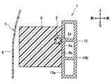
- FIG. 3 is a III-III cross-sectional view of the bumper portion of FIG. 2.
- the vehicle collision detection device 1 of this embodiment includes a hollow detection tube member 2, a pressure sensor 3, a power supply unit 4, a speed sensor 5, a collision detection ECU 6, and the like. Composed.
- the collision detection ECU 6 includes a collision determination unit 61, a low-pass filter 62, an electricity detection unit 63, a temperature calculation unit 64, and a threshold value correction unit 65.
- the vehicle collision detection device 1 detects a collision of an object (that is, a pedestrian) with a bumper 7 provided in front of the vehicle.
- the bumper 7 is mainly composed of a bumper cover 8, a bumper absorber 9, and a bumper reinforcement 10.
- the detection tube member 2 is a tube-shaped member having a hollow portion 2a formed therein and extending in the vehicle width direction (that is, the vehicle left-right direction). As shown in FIG. 3, the detection tube member 2 has a circular cross-sectional shape.
- the outer diameter of the detection tube member 2 is, for example, about 8 mm.
- the thickness of the peripheral wall of the detection tube member 2 is, for example, about 2 mm.
- the tube member for detection 2 is mounted in a groove portion 9a of a bumper absorber 9 described later, and is disposed at a position facing the front surface 10a of the bumper reinforcement 10 (that is, the vehicle front side).
- Both ends of the tube member for detection 2 are curved on the left and right outer sides of the bumper reinforcement 10 in the vehicle width direction, and are connected to a pressure sensor 3 to be described later.
- the cross-sectional shape of the detection tube member 2 is not limited to a circle, but may be a polygon such as a quadrangle.
- the detection tube member 2 of the present embodiment is made of a pressure-sensitive conductive elastomer in which an insulating synthetic rubber is mixed with a conductive material 2b (corresponding to a conductive member) that is conductive particles.
- a conductive material 2b corresponding to a conductive member
- silicone rubber is used as the synthetic rubber
- copper or the like is used as the conductive material 2b.
- ethylene propylene rubber (EPDM) or the like may be used as a material of the synthetic rubber.
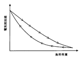
- the pressure-sensitive conductive elastomer has a characteristic that the electrical resistance value of the conductive material 2b changes with a change in the load applied to the synthetic rubber. Specifically, as shown in FIG. 7, when the load applied to the pressure-sensitive conductive elastomer increases, the electrical resistance value of the conductive material 2b decreases, and when the load load is eliminated, the electrical resistance value of the conductive material 2b increases. Become. This is because when the load is increased, a conduction path generated by contact between the conductive materials 2b increases.
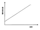
- the conductive material 2 b has an electrical property that the electrical resistance value increases in proportion to the temperature rise of the detection tube member 2.
- the temperature of the detection tube member 2 can be calculated from the correlation between the temperature of the conductive material 2b and the electrical resistance value.
- a conductive wire 2c is disposed inside the detection tube member 2 on the left end side in the vehicle width direction.
- the conductive wire 2c extends to the outside of the detection tube member 2 and is connected to the sensor portion 31 of the pressure sensor 3 disposed on the left side in the vehicle width direction.
- the conductive wire 2c is used to output the electrical resistance value of the detection tube member 2 to the sensor unit 31 of the pressure sensor 3 on the left side in the vehicle width direction.
- the pressure sensor 3 is disposed on the vehicle rear side with respect to the front surface 10a of the bumper reinforcement 10. Specifically, two pressure sensors 3 are installed on the left and right ends of the bumper cover 8, and are fixedly attached to the rear surface 10 b of the bumper reinforcement 10 by fastening with bolts (not shown). In this embodiment, redundancy and detection accuracy are ensured by installing two pressure sensors 3 in this way.
- the pressure sensor 3 is connected to both left and right ends of the detection tube member 2, and is configured to detect the pressure in the hollow portion 2a of the detection tube member 2.
- the pressure sensor 3 is a sensor device that detects a change in the pressure of gas, and detects a change in the pressure of air in the hollow portion 2 a of the tube member 2 for detection.
- the pressure sensor 3 is electrically connected to the collision detection ECU 6 via a transmission line, and outputs a signal proportional to the pressure to the collision detection ECU 6.
- the collision detection ECU 6 detects a pedestrian collision with the bumper 7 based on the pressure detection result by the pressure sensor 3.
- the collision detection ECU 6 is electrically connected to the pedestrian protection device 11.
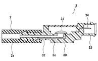
- the pressure sensor 3 includes a main body portion 30, a sensor portion 31, a pressure introduction pipe 32, and a connector portion 33.
- the main body 30 is a box-shaped case for housing the sensor unit 31.
- the sensor unit 31 is made of a substrate or the like on which a sensor element for detecting pressure is provided.
- the sensor unit 31 is electrically connected to the conductive wire 2c of the detection tube member 2 described above.
- the electrical resistance value of the detection tube member 2 is transmitted as a signal to the sensor unit 31 via the conductive wire 2c.
- a signal relating to the electrical resistance value transmitted to the sensor unit 31 is transmitted to the collision detection ECU 6 and received by the electrical detection unit 63 via a low-pass filter 62 described later.
- the pressure introduction tube 32 is a substantially cylindrical tube that introduces the pressure of the detection tube member 2 into the sensor unit 31, and is inserted into the detection tube member 2 from the main body unit 30.
- the sensor unit 31 detects a pressure change of the detection tube member 2 through the pressure introduction pipe 32.
- the sensor unit 31 is electrically connected to a connector 34 provided in the connector unit 33, and transmits a signal proportional to the pressure to the collision detection ECU 6 via the connector 34 and the transmission line (see FIG. 1).
- the power supply unit 4 supplies power to the conductive material 2b of the detection tube member 2. Specifically, it is electrically connected to the sensor part 31 of the pressure sensor 3 on the right side in the vehicle width direction, and applies a predetermined DC power supply voltage over the entire vehicle width direction of the detection tube member 2 (see FIG. 1). ).
- the power supplied by the power supply unit 4 may be an alternating voltage.
- Speed sensor 5 detects the speed of the vehicle.
- the speed sensor 5 outputs the detected vehicle speed as a speed signal to the collision detection ECU 6 via the transmission line.
- a collision detection ECU (Electronic Control Unit) 6 is mainly composed of a CPU, and controls the overall operation of the vehicle collision detection device 1. As shown in FIG. 5, the collision detection ECU 6 includes a collision determination unit 61, a low-pass filter 62, an electricity detection unit 63, a temperature calculation unit 64, and a threshold value correction unit 65.
- the collision detection ECU 6 is mainly composed of a CPU, and controls the overall operation of the vehicle collision detection apparatus 1. As shown in FIG. 1, the detection tube member 2, the pressure sensor 3, the speed sensor 5, the walking Each of the person protection devices 11 is electrically connected. The collision detection ECU 6 receives a pressure signal from the pressure sensor 3, a speed signal from the speed sensor 5, a signal related to an electrical resistance value from the detection tube member 2, and the like.
- the collision determination unit 61 determines whether or not an object (that is, a pedestrian) has collided with the bumper 7 by determining whether or not the pressure detection result by the pressure sensor 3 is equal to or greater than a predetermined threshold value. .
- the collision determination unit 61 of the present embodiment performs a collision determination using a threshold value corrected by a threshold value correction unit 65 described later.
- the collision determination unit 61 outputs a control signal for operating the pedestrian protection device 11.
- a low-pass filter (LPF: Low Pass Filter) 62 blocks a frequency signal higher than a predetermined value and passes only a low frequency as a signal.
- the low-pass filter 62 is a detection tube member having a conductive material 2b via the conductive wire 2c shown in FIG. 4, the sensor portion 31 of the pressure sensor 3, the connector 34, and the transmission line (see FIG. 1). 2 is electrically connected.
- a signal related to the electrical resistance value of the tube member for detection 2 is input to the low-pass filter 62 via the transmission line from the sensor unit 31.
- the low-pass filter 62 blocks disturbance noise such as a change in electrical resistance value due to electrical noise or a sudden change in electrical resistance value due to deformation of the detection tube member 2 at the time of a collision by blocking a signal in a high frequency range. It removes and outputs the signal regarding an electrical resistance value to the electric detection part 63 (refer FIG. 9).
- the electricity detection unit 63 detects a change in electrical properties of the detection tube member 2. Specifically, the electrical detection unit 63 detects a change in the electrical resistance value of the detection tube member 2 by receiving a signal related to the electrical resistance value of the detection tube member 2 via the low-pass filter 62.
- the temperature calculation unit 64 calculates the temperature of the detection tube member 2 based on the change in electrical properties of the detection tube member 2 detected by the electricity detection unit 63, that is, the change in electrical resistance value. Specifically, the temperature calculation unit 64 uses the correlation between the temperature and the electric resistance value of the detection tube member 2 shown in FIG. 8 to calculate the detection tube member from the electric resistance value of the detection tube member 2. Calculate the temperature of 2.
- the threshold correction unit 65 corrects the threshold used for the collision determination based on the temperature calculated by the temperature calculation unit 64. Specifically, as shown in FIG. 10, the threshold correction unit 65 reduces the threshold as the temperature calculated by the temperature calculation unit 64 is lower, and corrects the threshold so that the threshold is increased when the calculated temperature is high. Do. In FIG. 10, the threshold value before correction is indicated by a dotted line, and the threshold value after correction is indicated by a solid line.
- the bumper 7 is for reducing an impact at the time of a vehicle collision, and includes a bumper cover 8, a bumper absorber 9, a bumper reinforcement 10, and the like.
- the bumper cover 8 is provided so as to cover the components of the bumper 7 and is a resin member such as polypropylene.
- the bumper cover 8 constitutes the appearance of the bumper 7 and at the same time constitutes a part of the appearance of the entire vehicle.
- the bumper absorber 9 is disposed at a position facing the front surface 10a of the bumper reinforcement 10 (that is, on the vehicle front side).
- the bumper absorber 9 is a member responsible for shock absorption in the bumper 7, and is made of, for example, foamed polypropylene.
- a groove 9a for mounting the detection tube member 2 is formed in the rear surface 9b of the bumper absorber 9 along the vehicle width direction.
- the groove 9a has a rectangular cross-sectional shape and extends in the vehicle width direction.
- the length of the groove 9a in the vehicle front-rear direction is set to be approximately the same as the length of the detection tube member 2 in the vehicle front-rear direction (that is, the length of the outer diameter). In this case, the longitudinal length of the groove 9a is about 8 mm. Further, the length of the groove 9a in the vehicle vertical direction is set to be equal to or longer than the length of the detection tube member 2 in the vehicle vertical direction (that is, the length of the outer diameter). In this case, the vertical length of the groove 9a is set to about 10 mm.
- the bumper reinforcement 10 is a rigid member made of metal such as aluminum which is disposed in the bumper cover 8 and extends in the vehicle width direction, and is a hollow member having a beam provided in the center of the interior as shown in FIG. It is.
- the bumper reinforcement 10 has a front surface 10a that is a surface on the front side of the vehicle and a rear surface 10b that is a surface on the rear side of the vehicle. As shown in FIGS. 1 and 2, the bumper reinforcement 10 is attached to the front end of a side member 12 that is a pair of metal members extending in the vehicle front-rear direction.
- the pressure sensor 3 is disposed on the rear surface 10b of the bumper reinforcement 10, and a bumper cover 8 provided in front of the vehicle is subjected to an impact caused by a collision with a pedestrian or vehicle in front of the vehicle.
- the presence of the bumper reinforcement 10 protects the direct transmission to the pressure sensor 3.
- a pop-up hood is used as the pedestrian protection device 11.
- This pop-up hood raises the rear end of the engine hood instantly after detecting a vehicle collision, increases the clearance between the pedestrian and hard parts such as the engine, and uses that space to collide with the pedestrian's head. It absorbs energy and reduces the impact on the pedestrian's head.
- a cowl airbag or the like that cushions a pedestrian's impact by deploying an airbag from above the engine hood outside the vehicle body to the lower part of the front window may be used.
- the bumper cover 8 is deformed by an impact caused by the collision with the pedestrian.
- the bumper absorber 9 is deformed while absorbing an impact, and at the same time, the detection tube member 2 is also deformed.
- the pressure in the hollow portion 2 a of the detection tube member 2 rises rapidly, and this pressure change is transmitted to the pressure sensor 3.
- the electrical resistance value of the detection tube member 2 immediately before the occurrence of the collision is transmitted to the sensor unit 31 of the pressure sensor 3 through the conductive wire 2c. Furthermore, an electrical resistance value is output from the sensor unit 31 to the collision detection ECU 6 via the connector 34 and the transmission line.
- the electrical resistance value sent to the collision detection ECU 6 is sent to the electricity detection unit 63 via the low pass filter 62.
- the temperature calculation part 64 detects the temperature of the tube member 2 for a detection based on the electrical resistance value detected by the electricity detection part 63.
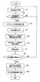
- the flow of the collision determination process performed by the vehicle collision detection apparatus 1 having the above-described configuration will be described with reference to the flowchart of FIG.
- this flowchart is an example, and the present invention is not limited to this.
- it is determined whether or not a collision with a pedestrian that requires the operation of the pedestrian protection device 11 has occurred based on the detection results of the pressure sensor 3 and the speed sensor 5.
- the collision detection ECU 6 of the vehicle collision detection device 1 acquires the vehicle speed from the output from the speed sensor 5 (S1), and determines whether or not the vehicle speed is within a predetermined operating range. (S2).
- the operating range of the vehicle speed is, for example, a range of 25 km to 55 km / h. This operating range is due to the fact that the speed at which the pedestrian protection function of the pedestrian protection device 11 acts effectively is determined by conditions such as the vehicle shape.
- effective mass refers to the mass calculated from the detection value of the pressure sensor 3 at the time of collision using the relationship between momentum and impulse.
- the value of the detected pressure sensor 3 is different for a collision object (an object with an OFF requirement) such as a roadside marker having a mass different from that of a pedestrian (an object with an ON requirement).
- a threshold value between the effective mass of the human body and the mass of another assumed collision object, it is possible to classify the types of the collision object.
- the effective mass is calculated by dividing the constant integral value of the pressure value detected by the pressure sensor 3 at a predetermined time by the vehicle speed detected by the speed sensor 5 as shown in the following equation.
- M ( ⁇ P (t) dt) / V (Expression 1)
- P is a value detected by the pressure sensor 3 at a predetermined time
- t is a predetermined time (for example, several ms to several tens of ms)
- V is a vehicle speed at the time of collision.
- E 1/2 ⁇ MV 2 representing the kinetic energy E of the collided object.
- the collision detection ECU 6 acquires the electric resistance value of the detection tube member 2 (S5). Specifically, based on the fact that the electrical detection unit 63 of the collision detection ECU 6 receives a signal related to the electrical resistance value of the detection tube member 2 via the low-pass filter 62, the electrical resistance value of the detection tube member 2 is determined. To detect. In addition, the electric detection part 63 is acquiring the electrical resistance value continuously for every predetermined time.
- the low-pass filter 62 passes only the low frequency.
- the low-pass filter 62 cuts off a signal in a high frequency range, thereby causing an electrical resistance value due to electrical noise, a sudden change in electrical resistance value accompanying deformation of the detection tube member 2 when a collision occurs, or the like. And a signal related to the electric resistance value is output to the electric detector 63. That is, when a collision occurs, the electrical resistance value of the detection tube member 2 changes abruptly, so that a frequency signal higher than a predetermined value is sent to the low-pass filter 62.
- the low-pass filter 62 removes a signal in a high frequency range when the collision occurs. As a result, the electric resistance value of the detection tube member 2 immediately before the collision can be detected as a measured value, and the temperature immediately before the collision can be detected (see FIG. 9).
- the temperature calculation unit 64 of the collision detection ECU 6 calculates the temperature of the detection tube member 2 (S6).
- the temperature calculation unit 64 calculates the temperature of the detection tube member 2 by using a signal relating to the electrical resistance value of the detection tube member 2 sent from the electricity detection unit 63 based on the proportional relationship shown in FIG. To do.
- the threshold correction unit 65 of the collision detection ECU 6 corrects the threshold used for collision determination (S7). Specifically, as shown in FIG. 10, the threshold value correction unit 65 corrects the threshold value so that the threshold value decreases as the calculated temperature by the temperature calculation unit 64 decreases, and the threshold value increases as the calculated temperature increases. . That is, the threshold correction unit 65 corrects the collision determination threshold to increase in proportion to the temperature rise. Note that the threshold correction method by the threshold correction unit 65 is not limited to this. For example, the threshold may be decreased only when the temperature calculated by the temperature calculation unit 64 is equal to or lower than a predetermined temperature.
- the collision determination unit 61 of the collision detection ECU 6 determines whether or not the calculated effective mass is greater than or equal to the threshold corrected by the threshold correction unit 65 (S8).
- the process returns to S1, and when the effective mass is equal to or more than the corrected threshold value (S8: Yes), the collision determination unit 61 of the collision detection ECU 6 It is determined that a collision with a pedestrian has occurred (S9), a control signal for operating the pedestrian protection device 11 is output, and the pedestrian protection device 11 is operated (S10). Thereby, the impact to the pedestrian by the collision with the pedestrian of a vehicle is reduced.
- the vehicle collision detection apparatus 1 is disposed in the vehicle bumper 7 so as to extend in the vehicle width direction on the vehicle front side of the bumper reinforcement 10 and has a hollow portion therein. 2a is formed, and the pressure in the hollow portion 2a of the detection tube member 2 including the conductive material 2b (conductive member) whose electrical properties change with temperature change is determined.
- a predetermined threshold By determining whether the pressure sensor 3 to be detected and whether the pressure detection result by the pressure sensor 3 is equal to or greater than a predetermined threshold, whether or not an object (that is, a pedestrian) has collided with the bumper 7 is determined.
- an electric detection unit (63, S5) for detecting a change in electrical properties of the detection tube member 2.
- a change in the electrical property of the detection tube member 2 is detected by the electric detection unit 63, and the temperature of the detection tube member 2 is accurately detected by the temperature calculation unit 64 based on the detection result. Can do.
- an appropriate collision determination can be performed according to the temperature of the detection tube member 2 itself. Therefore, it is possible to detect a collision of a pedestrian or the like with high accuracy regardless of the temperature change of the detection tube member 2.
- the temperature of the detection tube member 2 itself can be detected more accurately with a simple configuration, and the collision detection accuracy is reliably improved. it can.
- the electricity detection unit 63 detects a change in the electrical resistance value of the detection tube member 2. According to this configuration, since the change in the electric resistance value of the detection tube member 2 can be detected by the electric detection unit 63, the correlation between the electric resistance value of the detection tube member 2 and the temperature is verified in advance. Thus, it is possible to accurately grasp the temperature of the detection tube member 2.
- the vehicle collision detection device 1 includes a threshold value correction unit (65, S7) that corrects the threshold value based on the temperature calculated by the temperature calculation unit 64.
- the collision determination unit 61 performs a collision determination using the threshold corrected by the threshold correction unit 65.
- the threshold value correction unit 65 corrects the threshold value such that the lower the calculated temperature by the temperature calculation unit 64, the smaller the threshold value, and the higher the calculated temperature, the larger the threshold value.
- the threshold value is corrected by the threshold value correction unit 65 based on the temperature calculated by the temperature calculation unit 64, and the collision determination unit 61 performs the collision determination using the corrected threshold value. It can be performed. That is, the threshold value correction unit 65 corrects the threshold value so that the threshold value decreases as the calculated temperature by the temperature calculation unit 64 decreases, and the threshold value increases as the calculated temperature increases. A threshold can be set.
- the pedestrian protection device 11 when the detection tube member 2 is at a low temperature, the output of the pressure sensor 3 with respect to a predetermined load is small. Therefore, if the threshold value before correction indicated by the dotted line in FIG. The output of 3 becomes less than the threshold value, and the pedestrian protection device 11 may not operate. Therefore, when the temperature calculated by the temperature calculation unit 64 is low, the threshold value is corrected to a small value (see the corrected threshold value in FIG. 10), and even if the temperature of the detection tube member 2 is low, the ON requirement collision occurs. When this occurs, the pedestrian protection device 11 can be reliably operated.
- the detection tube member 2 is made of a pressure-sensitive conductive elastomer. According to this configuration, since the detection tube member 2 is made of a pressure-sensitive conductive elastomer having elasticity, the detection tube member 2 can be appropriately deformed at the time of collision, and the electric resistance of the pressure-sensitive conductive elastomer The temperature of the detection tube member 2 can be detected based on the change in value.
- the electricity detection unit 63 detects a change in electrical properties of the tube member for detection 2 via the low-pass filter 62.
- the temperature of the detection tube member 2 immediately before the occurrence of the collision can be measured by detecting a change in the electrical property of the detection tube member 2 via the low-pass filter 62 (see FIG. 9). ). That is, the detection tube member 2 suddenly changes its electrical properties (that is, its electric resistance value) with the occurrence of a collision, but by cutting off a signal in a high frequency region where the change in the electric resistance value is abrupt.
- the temperature of the tube member for detection 2 can be detected based on receiving the signal immediately before the collision.
- the collision detection ECU 6 includes a collision determination unit 61, a low-pass filter 62, an electricity detection unit 63, a temperature calculation unit 64, as shown in FIG. And an output correction unit 66. That is, in the second embodiment, an output correction unit 66 is provided instead of the threshold correction unit 65 in the first embodiment.
- the collision detection ECU 6 of the vehicle collision detection device 1 acquires the vehicle speed from the output from the speed sensor 5 (S21), as in the first embodiment, and the vehicle speed is predetermined. It is determined whether it is within the operating range (S22). If the vehicle speed is not within the operating range (S22: No), the process returns to S21. If the vehicle speed is within the operating range (S22: Yes), the collision detection ECU 6 acquires the detection value of the pressure sensor 3 (S23). ).
- the collision detection ECU 6 acquires the electrical resistance value of the detection tube member 2 (S24). Specifically, the electric detection unit 63 of the collision detection ECU 6 receives a signal related to the electric resistance value of the detection tube member 2 via the low-pass filter 62 (see FIG. 12). As described above, the low-pass filter 62 removes disturbance noise such as a change in electrical resistance value due to electrical noise and a sudden change in electrical resistance value due to deformation of the detection tube member 2 when a collision occurs. A signal related to the electrical resistance value is output to the electrical detection unit 63. By using this low-pass filter 62, the electric resistance value of the detection tube member 2 immediately before the occurrence of the collision can be detected.
- the temperature calculation unit 64 of the collision detection ECU 6 calculates the temperature of the detection tube member 2 (S25).
- the temperature calculation unit 64 calculates the temperature of the detection tube member 2 based on the signal related to the electrical resistance value sent from the electricity detection unit 63.
- the output correction unit 66 of the collision detection ECU 6 corrects the output of the pressure sensor 3 (S26). Specifically, the output of the pressure sensor 3 is corrected based on the calculated temperature of the detection tube member 2 in consideration of the temperature characteristics of the bumper absorber 9 and the detection tube member 2 that transmit the impact. For example, as illustrated in FIG. 13, the output correction unit 66 performs correction so as to increase the output of the pressure sensor 3 when the temperature calculated by the temperature calculation unit 64 is low (see the upward arrow in FIG. 13). On the other hand, when the temperature calculated by the temperature calculation unit 64 is high, correction is performed to reduce the output of the pressure sensor 3 (see the downward arrow in FIG. 13). Thereby, the output of the pressure sensor 3 increases as the temperature increases, and the collision detection accuracy is prevented from varying with temperature change.
- the deformation amount of the detection tube member 2 at the time of collision is affected by the temperature characteristics of the bumper absorber 9.
- the bumper absorber 9 has a temperature characteristic that the deformation amount is small at a low temperature and the deformation amount is large at a high temperature. For this reason, it is assumed that the deformation amount of the detection tube member 2 at the time of collision is small at a low temperature and large at a high temperature. Therefore, the output of the pressure sensor 3 is small at low temperatures and large at high temperatures.
- the output of the pressure sensor 3 is corrected according to the temperature calculated by the temperature calculation unit 64. is doing.
- the temperature characteristics of the detection tube member 2 and the bumper absorber 9 are different depending on the respective materials.
- the output of the pressure sensor 3 may decrease as the temperature increases. is there.
- the output correction unit 66 performs correction so as to decrease the output of the pressure sensor 3 when the temperature calculated by the temperature calculation unit 64 is low, and increases the output of the pressure sensor 3 when the calculated temperature is high. Correct as follows.
- the collision determination unit 61 of the collision detection ECU 6 calculates the above-described effective mass based on the detection value of the pressure sensor 3 corrected by the output correction unit 66 (see FIG. 12) (S27). . Then, the collision determination unit 61 of the collision detection ECU 6 determines whether or not the calculated effective mass is equal to or greater than a predetermined threshold (S28).
- the process returns to S1, and when the effective mass is equal to or greater than the threshold value (S28: Yes), the collision determination unit 61 of the collision detection ECU 6 determines that the collision with the pedestrian of the vehicle has occurred. It determines with having generate
- the vehicle collision detection apparatus 1 includes an output correction unit (66, S26) that corrects the sensor output from the pressure sensor 3 based on the temperature calculated by the temperature calculation unit 64.
- the collision determination unit (61, S28) performs collision determination using the sensor output corrected by the output correction unit 66.
- the output correction unit 66 corrects the sensor output from the pressure sensor 3 based on the temperature calculated by the temperature calculation unit 64, and the collision determination unit 61 uses the sensor output corrected by the output correction unit 66. Since the collision determination is performed, the collision determination can be accurately performed according to the temperature of the detection tube member 2 itself. Therefore, it is possible to detect the collision of the pedestrian with high accuracy regardless of the temperature change of the detection tube member 2.
- the output correction unit 66 corrects the sensor output so that the sensor output is increased as the calculated temperature by the temperature calculating unit 64 is lower and the sensor output is decreased as the calculated temperature is higher.
- the output correction unit 66 can correct the sensor output such that the sensor output is increased as the calculated temperature by the temperature calculating unit 64 is lower and the sensor output is decreased as the calculated temperature is higher. Therefore, the collision determination by the collision determination unit 61 can be more accurately performed by appropriately correcting the sensor output according to the calculated temperature. That is, when the temperature is low, the output of the pressure sensor 3 with respect to the predetermined load is reduced, so that the sensor output is increased. When the temperature is high, the output of the pressure sensor 3 with respect to the predetermined load is increased, so that the sensor output is decreased. Thus, regardless of the temperature change of the detection tube member 2, the pressure change in the hollow portion 2a of the detection tube member 2 at the time of collision can be detected with high accuracy.
- the pedestrian protection device 11 may not operate (see the low temperature side of the pre-correction ON requirement in FIG. 13). Therefore, when the temperature calculated by the temperature calculation unit 64 is low, the sensor output is corrected so as to increase, so that even when the temperature of the detection tube member 2 is low, it is ensured when the ON requirement collision occurs.
- the pedestrian protection device 11 can be activated.
- the output of the pressure sensor 3 becomes large when the tube member 2 for detection is high temperature, the output of the pressure sensor 3 becomes more than a threshold value even if it is a collision of OFF requirements, and the pedestrian protection apparatus 11 will operate
- the present disclosure is not limited to the above-described embodiments, and various modifications or expansions can be made without departing from the spirit of the present disclosure.
- the effective mass is calculated based on the pressure detection result, and when the effective mass is equal to or greater than the collision determination threshold in the collision determination process, although it is determined that a collision has occurred, the present invention is not limited to this. That is, the pressure detection result may be used as it is, and for example, a collision determination may be made by comparing with a threshold for each collision determination using a pressure value, a pressure change rate, or the like.
- the power supply unit 4 is provided separately from the pressure sensor 3, but a power supply unit may be provided inside the pressure sensor 3.
- a power supply unit 3Ra is provided inside a pressure sensor 3R arranged on the right side in the vehicle width direction.
- a grounded output detection resistor 3La is provided inside the pressure sensor 3L arranged on the left side in the vehicle width direction.
- the power supply unit 3Ra supplies a predetermined voltage Vin to the conductive material 2b of the detection tube member 2 from the right end portion in the vehicle width direction.
- the left end of the detection tube member 2 in the vehicle width direction is connected to the sensor portion 31 of the pressure sensor 3L via a conductive wire 2c (see FIG. 4).
- a predetermined DC power supply voltage is applied across the entire vehicle width direction from the right end to the left end of the detection tube member 2 by the power supply unit 3Ra.
- the sensor unit 31 of the pressure sensor 3L is connected to the collision detection ECU 6 via a transmission line, and outputs a signal proportional to the voltage value of the detection tube member 2 to the collision detection ECU 6.
- the output voltage value Vout is expressed by the following equation.
- the temperature of the tube member for detection 2 can be calculated by the temperature calculation unit 64. That is, since the resistance value R1 of the detection tube member 2 can be detected by detecting the output voltage value Vout, the detection value is detected using the above-described correlation between the temperature of the detection tube member 2 and the electrical resistance value. The temperature of the tube member 2 can be calculated. Also in this case, the same effect as the above embodiment can be obtained. Alternatively, the current value of the detection tube member 2 may be detected by the electricity detection unit 63, and the temperature of the detection tube member 2 may be calculated by the temperature calculation unit 64.
- the pressure-sensitive conductive elastomer is used as the material of the tube member 2 for detection, but is not limited thereto.
- the material of the tube member for detection 2 may be any material as long as it has a conductive member whose electrical properties change with changes in temperature.
- a conductive rubber in which carbon or the like is blended into a synthetic rubber as a conductive member may be used.
- a tube member made of synthetic rubber may be used in which conductive wires and conductive plates are arranged extending in the vehicle width direction as conductive members.
- conductive ink as a conductive material may be applied to the outer peripheral surface of the tube member.
- a conductive ink for example, an ink having a characteristic of positive temperature coefficient (PTC: Positive ⁇ ⁇ ⁇ Temperature Coefficient) is used. This ink has a characteristic that the electrical resistance value increases as the temperature increases, and the electrical resistance value decreases as the temperature decreases.
- PTC Positive ⁇ ⁇ ⁇ Temperature Coefficient
- the pressure sensor 3 shall be arrange
- the pressure sensor 3 may be disposed on the inner wall surface of the bumper reinforcement 10.
Landscapes
- Engineering & Computer Science (AREA)
- Mechanical Engineering (AREA)
- Force Measurement Appropriate To Specific Purposes (AREA)
Abstract
車両用衝突検知装置は、車幅方向に延びて、温度変化に伴って電気的性質が変化する導電部材(2b)を有する検出用チューブ部材(2)と、検出用チューブ部材の中空部(2a)内の圧力を検出する圧力センサ(3)と、圧力センサによる圧力検出結果が所定の閾値以上であるか否かを判定することで衝突判定を行う衝突判定部(61)と、検出用チューブ部材に電源を供給する電源供給部(4)と、検出用チューブ部材の電気的性質の変化を検出する電気検出部(63)と、電気検出部により検出される検出用チューブ部材の電気的性質の変化に基づいて、検出用チューブ部材の温度を算出する温度算出部(64)とを備える。
Description
本出願は、2015年6月23日に出願された日本特許出願2015-125727号に基づくもので、ここにその記載内容を援用する。
本開示は、車両の歩行者等との衝突を検知するための車両用衝突検知装置に関する。
従来、歩行者が車両に衝突した際、歩行者への衝撃を軽減するための歩行者保護装置を備えた車両がある。この車両では、バンパ部にセンサを備えた衝突検知装置を設ける。センサにより車両に歩行者等が衝突したことが検知された場合、歩行者保護装置を作動させ、歩行者への衝撃を和らげる。歩行者保護装置には、例えばポップアップフードと呼ばれるものがある。ポップアップフードは、車両の衝突検知時に、エンジンフードの後端を上昇させ、歩行者とエンジン等の硬い部品とのクリアランスを増加させ、そのスペースを用いて歩行者の頭部への衝突エネルギーを吸収し、頭部への衝撃を低減させる。
上記した車両用衝突検知装置には、車両のバンパ内におけるバンパレインフォースメントの車両前方側に、内部にチャンバ空間が形成されたチャンバ部材を配設し、このチャンバ空間内の圧力を圧力センサにより検出するようにしたものがある。この構成のものでは、バンパカバーへ歩行者等の物体が衝突すると、バンパカバーの変形に伴ってチャンバ部材が変形し、チャンバ空間に圧力変化が発生する。この圧力変化を圧力センサが検出することで歩行者の衝突を検知している。
近年、上記したチャンバ式の車両用衝突検知装置よりも、小型で搭載性に優れたチューブ部材を用いて衝突を検知するチューブ式の車両用衝突検知装置が提案されている。この車両用衝突検知装置は、車両のバンパ内においてバンパレインフォースメントの車両前方側に配設されたバンパアブソーバと、バンパアブソーバに車幅方向に沿って形成された溝部に装着される中空のチューブ部材と、チューブ部材内の圧力を検出する圧力センサとを備えて構成される。車両前方に歩行者等が衝突した際には、バンパアブソーバが衝撃を吸収しながら変形すると同時にチューブ部材も変形する。このとき、チューブ部材内の圧力が上昇し、この圧力変化を圧力センサにより検出することに基づいて、車両の歩行者との衝突を検知する。
上述したチューブ式の車両用衝突検知装置では、衝突時にバンパカバーの変形に伴って変形するチューブ部材の変形量は、バンパアブソーバの温度特性から影響を受ける。バンパアブソーバは、低温では変形量が小さく、高温では変形量が大きくなるという温度特性を有する。このため、衝突時におけるチューブ部材の変形量は、低温では変形量が小さく、高温では変形量が大きくなる。このように温度変化に伴って、所定の負荷荷重に対するチューブ部材の変形量が異なってくるので、圧力センサの出力が温度変化に伴ってばらつくことが想定される。従って、衝突検知精度を向上させるためには、温度変化に伴って圧力センサの出力がばらつくことにより衝突検知精度が低下することを抑止する必要があるという課題がある。
本開示は、歩行者等の衝突を温度変化に拘わらず高精度に検知可能な車両用衝突検知装置を提供することを目的とする。
本開示の一態様において、車両用衝突検知装置は、車両のバンパ内においてバンパレインフォースメントの車両前方側に車幅方向に延びて配設され、内部に中空部が形成されたものであって、温度変化に伴って電気的性質が変化する導電部材を有する検出用チューブ部材と、検出用チューブ部材の中空部内の圧力を検出する圧力センサと、圧力センサによる圧力検出結果が所定の閾値以上であるか否かを判定することで、バンパへ物体が衝突したか否かの衝突判定を行う衝突判定部と、検出用チューブ部材に電源を供給する電源供給部と、検出用チューブ部材の電気的性質の変化を検出する電気検出部と、電気検出部により検出される検出用チューブ部材の電気的性質の変化に基づいて、検出用チューブ部材の温度を算出する温度算出部と、を備える。
この構成によれば、電気検出部により検出用チューブ部材の電気的性質の変化を検出し、その検出結果に基づいて温度算出部により検出用チューブ部材の温度を算出することができる。これにより、検出用チューブ部材自体の温度に応じて適切な衝突判定を行うことができる。従って、検出用チューブ部材の温度変化に拘わらず歩行者等の衝突を高精度に検知することができる。また、検出用チューブ部材から離間した位置に別体の温度センサを設ける場合に比べて、簡易な構成で検出用チューブ部材自体の温度をより正確に検出でき、衝突検知精度を確実に向上できる。
[第1の実施形態]
第1の実施形態にかかる車両用衝突検知装置について、図1~図11を参照して説明する。図1及び図2に示すように、本実施形態の車両用衝突検知装置1は、中空の検出用チューブ部材2、圧力センサ3、電源供給部4、速度センサ5、衝突検知ECU6等を備えて構成される。衝突検知ECU6は、図5に示すように、衝突判定部61、ローパスフィルタ62、電気検出部63、温度算出部64、閾値補正部65を有して構成される。車両用衝突検知装置1は、車両前方に設けられたバンパ7への物体(即ち、歩行者)の衝突を検知する。バンパ7は、図3にも示すように、バンパカバー8、バンパアブソーバ9、バンパレインフォースメント10を主体として構成されている。
第1の実施形態にかかる車両用衝突検知装置について、図1~図11を参照して説明する。図1及び図2に示すように、本実施形態の車両用衝突検知装置1は、中空の検出用チューブ部材2、圧力センサ3、電源供給部4、速度センサ5、衝突検知ECU6等を備えて構成される。衝突検知ECU6は、図5に示すように、衝突判定部61、ローパスフィルタ62、電気検出部63、温度算出部64、閾値補正部65を有して構成される。車両用衝突検知装置1は、車両前方に設けられたバンパ7への物体(即ち、歩行者)の衝突を検知する。バンパ7は、図3にも示すように、バンパカバー8、バンパアブソーバ9、バンパレインフォースメント10を主体として構成されている。
検出用チューブ部材2は、図1及び図2に示すように、内部に中空部2aが形成され、車幅方向(即ち、車両左右方向)に延びているチューブ状の部材である。検出用チューブ部材2は、図3に示すように、円形の断面形状を有している。検出用チューブ部材2の外径は、例えば8mm程度である。また、検出用チューブ部材2の周壁の肉厚は、例えば2mm程度である。検出用チューブ部材2は、後述するバンパアブソーバ9の溝部9a内に装着され、バンパレインフォースメント10の前面10aに対向した位置(即ち、車両前方側)に配設される。検出用チューブ部材2の両端部は、バンパレインフォースメント10の車幅方向左右の外側にて湾曲し、後述する圧力センサ3に接続される。尚、検出用チューブ部材2の断面形状は、円形に限られず、四角形等の多角形であってもよい。
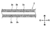
本実施形態の検出用チューブ部材2は、図6に示すように、絶縁性の合成ゴムに導電性粒子である導電材2b(導電部材に相当)を混ぜ合わせた感圧導電性エラストマーからなる。合成ゴムとしては、例えばシリコーンゴムを用い、導電材2bとしては、例えば銅等を用いるものとする。尚、合成ゴムの材質としては、他にもエチレンプロピレンゴム(EPDM)等でもよい。
感圧導電性エラストマーは、合成ゴムに負荷される荷重の変化に伴って、導電材2bの電気抵抗値が変化するという特性を有している。具体的には、図7に示すように、感圧導電性エラストマーに負荷される荷重が大きくなると導電材2bの電気抵抗値が小さくなり、負荷荷重をなくすと導電材2bの電気抵抗値が大きくなる。これは、負荷荷重が大きくなると、導電材2bどうしの接触により生じる導通経路が増加するためである。
また、導電材2bは、図8に示すように、検出用チューブ部材2の温度上昇に比例して電気抵抗値が大きくなるという電気的性質を有している。本実施形態の車両用衝突検知装置1では、導電材2bにおける温度と電気抵抗値との相関関係から、検出用チューブ部材2の温度を算出可能な構成となっている。
また、検出用チューブ部材2の車幅方向左端部側の内部には、図4に示すように、導電線2cが配設されている。導電線2cは、検出用チューブ部材2の外部に延び、車幅方向左側に配置された圧力センサ3のセンサ部31に接続される。導電線2cは、検出用チューブ部材2の電気抵抗値を、車幅方向左側の圧力センサ3のセンサ部31へ出力するために用いられる。
圧力センサ3は、バンパレインフォースメント10の前面10aよりも車両後方側に配置される。具体的には、圧力センサ3は、バンパカバー8内の左右両端部側に2つ設置され、バンパレインフォースメント10の後面10bに図示しないボルト等で締結することにより固定されて取り付けられる。本実施形態では、このように圧力センサ3を2つ設置することにより、冗長性及び検出精度を確保している。
圧力センサ3は、図4に示すように、検出用チューブ部材2の左右両端部に接続され、検出用チューブ部材2の中空部2a内の圧力を検出するように構成されている。具体的には、圧力センサ3は、気体の圧力変化を検出するセンサ装置であり、検出用チューブ部材2の中空部2a内の空気の圧力変化を検出する。圧力センサ3は、図1に示すように、伝送線を介して衝突検知ECU6に電気的に接続され、圧力に比例した信号を衝突検知ECU6へ出力する。衝突検知ECU6は、圧力センサ3による圧力検出結果に基づいて、バンパ7への歩行者の衝突を検知する。また、衝突検知ECU6は、歩行者保護装置11に電気的に接続されている。
また、圧力センサ3は、図4に示すように、本体部30と、センサ部31と、圧力導入管32と、コネクタ部33とを備えて構成される。本体部30は、センサ部31を収容するための箱状のケースである。センサ部31は、圧力検出用のセンサ素子等が設けられた基板等からなる。このセンサ部31は、上述した検出用チューブ部材2の導電線2cに電気的に接続されている。検出用チューブ部材2の電気抵抗値は、導電線2cを介してセンサ部31に信号として送信される。センサ部31に送信された電気抵抗値に関する信号は、衝突検知ECU6へ送信され、後述のローパスフィルタ62を介して電気検出部63により受信される。
圧力導入管32は、検出用チューブ部材2の圧力をセンサ部31に導入する略円筒状の管であり、本体部30から検出用チューブ部材2内に差し込まれている。センサ部31は、圧力導入管32を介して検出用チューブ部材2の圧力変化を検出する。センサ部31は、コネクタ部33に設けられたコネクタ34に電気的に接続されており、圧力に比例した信号をコネクタ34及び伝送線を介して衝突検知ECU6へ送信する(図1参照)。
電源供給部4は、検出用チューブ部材2の導電材2bに電源を供給する。具体的には、車幅方向右側の圧力センサ3のセンサ部31に電気的に接続され、検出用チューブ部材2の車幅方向全体に亘って、所定の直流電源電圧を印加する(図1参照)。尚、電源供給部4により供給される電源は、交流電圧であってもよい。
速度センサ5は、車両の速度を検出する。速度センサ5は、検出した車両の速度を速度信号として伝送線を介して衝突検知ECU6に出力する。
衝突検知ECU(Electronic Control Unit)6は、CPUを主体として構成され、車両用衝突検知装置1の動作全般を制御する。衝突検知ECU6は、図5に示すように、衝突判定部61と、ローパスフィルタ62と、電気検出部63と、温度算出部64と、閾値補正部65とを有している。
衝突検知ECU6は、CPUを主体として構成され、車両用衝突検知装置1の動作全般を制御するものであり、図1に示すように、検出用チューブ部材2、圧力センサ3、速度センサ5、歩行者保護装置11のそれぞれに電気的に接続されている。衝突検知ECU6には、圧力センサ3からの圧力信号、速度センサ5からの速度信号、及び検出用チューブ部材2からの電気抵抗値に関する信号等が入力される。
衝突判定部61は、圧力センサ3による圧力検出結果が所定の閾値以上であるか否かを判定することで、バンパ7へ物体(即ち、歩行者)が衝突したか否かの衝突判定を行う。本実施形態の衝突判定部61は、後述する閾値補正部65により補正された閾値を用いて衝突判定を行う。衝突判定部61は、車両の歩行者との衝突が発生したと判定した場合、歩行者保護装置11を作動させる制御信号を出力する。
ローパスフィルタ(LPF:Low Pass Filter)62は、所定値よりも高い周波数信号を遮断し、低域周波数のみを信号として通過させる。本実施形態では、ローパスフィルタ62は、図4に示す導電線2c、圧力センサ3のセンサ部31、コネクタ34、及び伝送線(図1参照)を介して、導電材2bを有する検出用チューブ部材2と電気的に接続されている。ローパスフィルタ62には、センサ部31から伝送線を介して、検出用チューブ部材2の電気抵抗値に関する信号が入力される。ローパスフィルタ62は、高周波域の信号を遮断することで、電気的ノイズによる電気抵抗値の変化や、衝突時における検出用チューブ部材2の変形に伴う急激な電気抵抗値の変化などの外乱ノイズを除去し、電気検出部63へ電気抵抗値に関する信号を出力する(図9参照)。
電気検出部63は、検出用チューブ部材2の電気的性質の変化を検出する。具体的には、電気検出部63は、ローパスフィルタ62を介して検出用チューブ部材2の電気抵抗値に関する信号を受信することにより、検出用チューブ部材2の電気抵抗値の変化を検出する。
温度算出部64は、電気検出部63により検出された検出用チューブ部材2の電気的性質の変化、即ち電気抵抗値の変化に基づいて、検出用チューブ部材2の温度を算出する。具体的には、温度算出部64は、図8に示す検出用チューブ部材2の温度と電気抵抗値との間の相関関係を用いて、検出用チューブ部材2の電気抵抗値から検出用チューブ部材2の温度を算出する。
閾値補正部65は、温度算出部64による算出温度に基づいて、衝突判定に用いる閾値を補正する。具体的には、閾値補正部65は、図10に示すように、温度算出部64による算出温度が低いほど閾値を小さくし、算出温度が高温の場合に閾値を大きくするように閾値の補正を行う。なお、図10には補正前の閾値が点線で示され、補正後の閾値が実線で示されている。
バンパ7は、車両の衝突時における衝撃を和らげるためのものであり、バンパカバー8、バンパアブソーバ9、バンパレインフォースメント10等から構成される。バンパカバー8は、バンパ7の構成部品を覆うように設けられ、ポリプロピレン等の樹脂製の部材である。バンパカバー8は、バンパ7の外観を構成すると同時に、車両全体の外観の一部を構成する。
バンパアブソーバ9は、バンパレインフォースメント10の前面10aに対向する位置(即ち、車両前方側)に配設される。バンパアブソーバ9は、バンパ7において衝撃吸収の作用を受け持つ部材であり、例えば発泡ポリプロピレン等からなる。
バンパアブソーバ9の後面9bには、図3に示すように、検出用チューブ部材2を装着するための溝部9aが車幅方向に沿って形成されている。この溝部9aは、矩形の断面形状を有し、車幅方向に延びている。
溝部9aの車両前後方向の長さは、検出用チューブ部材2の車両前後方向の長さ(即ち、外径の長さ)と同程度に設定されている。この場合、溝部9aの前後長さは、8mm程度である。また、溝部9aの車両上下方向の長さは、検出用チューブ部材2の車両上下方向の長さ(即ち、外径の長さ)以上に設定されている。この場合、溝部9aの上下長さは、10mm程度に設定されている。
バンパレインフォースメント10は、バンパカバー8内に配設されて車幅方向に延びるアルミニウム等の金属製の剛性部材であって、図3に示すように、内部中央に梁が設けられた中空部材である。また、バンパレインフォースメント10は、車両前方側の面である前面10aと、車両後方側の面である後面10bとを有している。このバンパレインフォースメント10は、図1及び図2に示すように、車両前後方向に延びる一対の金属製部材であるサイドメンバ12の前端に取り付けられる。
通常、車両の衝突事故においては、車両の進行方向(即ち、車両前方)に存在する歩行者や車両と衝突する場合が多い。このため、本実施形態では、圧力センサ3をバンパレインフォースメント10の後面10bに配設して、車両前方の歩行者や車両との衝突に伴う衝撃が、車両前方に設けられたバンパカバー8等から圧力センサ3に直接伝わることをバンパレインフォースメント10の存在によって保護している。
歩行者保護装置11としては、例えばポップアップフードを用いる。このポップアップフードは、車両の衝突検知後瞬時に、エンジンフードの後端を上昇させ、歩行者とエンジン等の硬い部品とのクリアランスを増加させ、そのスペースを用いて歩行者の頭部への衝突エネルギーを吸収し、歩行者の頭部への衝撃を低減させるものである。尚、ポップアップフードの代わりに、車体外部のエンジンフード上からフロントウインド下部にかけてエアバッグを展開させて歩行者の衝撃を緩衝するカウルエアバッグ等を用いてもよい。
本実施形態における車両用衝突検知装置1の衝突時の動作について説明する。車両前方に歩行者等の物体が衝突した際には、バンパカバー8が歩行者との衝突による衝撃により変形する。続いて、バンパアブソーバ9が衝撃を吸収しながら変形すると同時に、検出用チューブ部材2も変形する。このとき、検出用チューブ部材2の中空部2a内の圧力が急上昇し、この圧力変化が圧力センサ3に伝達する。
また、本実施形態では、衝突発生直前の検出用チューブ部材2の電気抵抗値が、導電線2cを介して圧力センサ3のセンサ部31へ送信される。更に、センサ部31からコネクタ34及び伝送線を介して、衝突検知ECU6へ電気抵抗値が出力される。衝突検知ECU6に送られた電気抵抗値は、ローパスフィルタ62を介して電気検出部63へ送信される。そして、温度算出部64は、電気検出部63により検出される電気抵抗値に基づいて、検出用チューブ部材2の温度を検出する。
次に、上記構成を有する車両用衝突検知装置1による衝突判定処理の流れについて、図11のフローチャートも参照して説明する。ただし、このフローチャートは一例であり、これに限定されるものではない。本実施形態の衝突判定処理においては、圧力センサ3及び速度センサ5の検出結果に基づいて、歩行者保護装置11の作動を要する歩行者との衝突が発生したか否かの判定を行う。
まず、図11のフローチャートにおいて、車両用衝突検知装置1の衝突検知ECU6は、速度センサ5からの出力により車両速度を取得し(S1)、車両速度が所定の作動範囲内か否かの判定を行っている(S2)。この車両速度の作動範囲としては、例えば時速25km~55kmの範囲であるとする。この作動範囲は、歩行者保護装置11の歩行者保護機能が有効に作用する速度が車両形状等の条件によって決まっていることによる。
車両速度が作動範囲内でない場合には(S2:No)、S1に戻り、車両速度が作動範囲内の場合(S2:Yes)、衝突検知ECU6は、圧力センサ3の検出値を取得し(S3)、有効質量を算出する(S4)。
ここで、「有効質量」とは、衝突時における圧力センサ3の検出値より、運動量と力積の関係を利用して算出する質量をいう。車両と物体との衝突が発生した場合、歩行者(ON要件の対象物)とは質量の異なるロードサイドマーカ等の衝突物(OFF要件の対象物)では、検知される圧力センサ3の値が異なる。このため、人体の有効質量と、想定される他の衝突物の質量との間に閾値を設定することにより、衝突物の種類を切り分けることが可能となる。この有効質量は、次式に示すように、圧力センサ3により検出される圧力の値の所定時間における定積分値を、速度センサ5により検出される車両速度で割ることにより算出される。
M=(∫P(t)dt)/V・・・(式1)
ここで、Mは有効質量、Pは所定時間における圧力センサ3による検出値、tは所定時間(例えば、数ms~数十ms)、Vは衝突時の車両速度を示している。尚、有効質量を算出する方法には、他にも、衝突した物体の運動エネルギーEを表す式E=1/2・MV2を用いて算出することが可能である。この場合、有効質量は、M=2・E/V2により算出される。
ここで、Mは有効質量、Pは所定時間における圧力センサ3による検出値、tは所定時間(例えば、数ms~数十ms)、Vは衝突時の車両速度を示している。尚、有効質量を算出する方法には、他にも、衝突した物体の運動エネルギーEを表す式E=1/2・MV2を用いて算出することが可能である。この場合、有効質量は、M=2・E/V2により算出される。
次に、衝突検知ECU6は、検出用チューブ部材2の電気抵抗値を取得する(S5)。具体的には、衝突検知ECU6の電気検出部63が、ローパスフィルタ62を介して検出用チューブ部材2の電気抵抗値に関する信号を受信することに基づいて、検出用チューブ部材2の電気抵抗値を検出する。尚、電気検出部63は、所定時間ごとに継続して電気抵抗値の取得を行っている。
ローパスフィルタ62(LPF:Low Pass Filter)は、低域周波数のみを通過させる。本実施形態では、ローパスフィルタ62は、高周波域の信号を遮断することで、電気的ノイズによる電気抵抗値や、衝突発生時における検出用チューブ部材2の変形に伴う急激な電気抵抗値の変化などの外乱ノイズを除去し、電気抵抗値に関する信号を電気検出部63へ出力する。即ち、衝突発生時においては、検出用チューブ部材2の電気抵抗値が急激に変化するため、所定値よりも高い周波数信号がローパスフィルタ62へ送られてくる。ローパスフィルタ62は、この衝突発生時の高周波域の信号を除去する。これにより、衝突直前の検出用チューブ部材2の電気抵抗値を測定値として検出することが可能となり、衝突直前の温度を検出可能となっている(図9参照)。
次に、衝突検知ECU6の温度算出部64は、検出用チューブ部材2の温度を算出する(S6)。ここで、検出用チューブ部材2の温度と電気抵抗値との間には所定の相関関係、この場合、図6に示す比例関係がある。従って、温度算出部64は、図6に示す比例関係に基づいて、電気検出部63から送られる検出用チューブ部材2の電気抵抗値に関する信号を用いることにより、検出用チューブ部材2の温度を算出する。
続いて、衝突検知ECU6の閾値補正部65が、衝突判定に用いる閾値を補正する(S7)。具体的には、閾値補正部65は、図10に示すように、温度算出部64による算出温度が低いほど閾値を小さくし、算出温度が高いほど閾値を大きくするように、閾値の補正を行う。即ち、閾値補正部65は、温度上昇に比例して衝突判定の閾値が大きくなるように補正する。尚、閾値補正部65による閾値の補正方法は、これに限られず、例えば、温度算出部64による算出温度が所定温度以下の場合にだけ、閾値を小さくしてもよい。
次に、衝突検知ECU6の衝突判定部61は、算出した有効質量が閾値補正部65により補正された閾値以上か否かの判定を行う(S8)。有効質量が補正された閾値未満の場合には(S8:No)、S1に戻り、有効質量が補正された閾値以上の場合(S8:Yes)、衝突検知ECU6の衝突判定部61は、車両の歩行者との衝突が発生したものと判定し(S9)、歩行者保護装置11を作動させる制御信号を出力して、歩行者保護装置11を作動させる(S10)。これにより、車両の歩行者との衝突による歩行者への衝撃を低減させる。
以上説明したように、第1の実施形態の車両用衝突検知装置1は、車両のバンパ7内においてバンパレインフォースメント10の車両前方側に車幅方向に延びて配設され、内部に中空部2aが形成されたものであって、温度変化に伴って電気的性質が変化する導電材2b(導電部材)を有する検出用チューブ部材2と、検出用チューブ部材2の中空部2a内の圧力を検出する圧力センサ3と、圧力センサ3による圧力検出結果が所定の閾値以上であるか否かを判定することで、バンパ7へ物体(即ち、歩行者)が衝突したか否かの衝突判定を行う衝突判定部(61,S8)と、検出用チューブ部材2に電源を供給する電源供給部4と、検出用チューブ部材2の電気的性質の変化を検出する電気検出部(63,S5)と、電気検出部63により検出される検出用チューブ部材2の電気的性質の変化に基づいて、検出用チューブ部材2の温度を検出する温度算出部(64,S6)と、を備える。
この構成によれば、電気検出部63により検出用チューブ部材2の電気的性質の変化を検出し、その検出結果に基づいて温度算出部64により検出用チューブ部材2の温度を正確に検出することができる。これにより、検出用チューブ部材2自体の温度に応じて適切な衝突判定を行うことができる。従って、検出用チューブ部材2の温度変化に拘わらず歩行者等の衝突を高精度に検知することができる。また、検出用チューブ部材2から離間した位置に別体の温度センサを設ける場合に比べて、簡易な構成で検出用チューブ部材2自体の温度をより正確に検出でき、衝突検知精度を確実に向上できる。
また、電気検出部63は、検出用チューブ部材2の電気抵抗値の変化を検出する。この構成によれば、電気検出部63により検出用チューブ部材2の電気抵抗値の変化を検出することができるので、検出用チューブ部材2の電気抵抗値と温度との相関関係を予め検証しておくことで、検出用チューブ部材2の温度を正確に把握することが可能である。
また、車両用衝突検知装置1は、温度算出部64による算出温度に基づいて、閾値を補正する閾値補正部(65,S7)を備えている。衝突判定部61は、閾値補正部65により補正された閾値を用いて衝突判定を行う。閾値補正部65は、温度算出部64による算出温度が低いほど閾値を小さくし、算出温度が高いほど閾値を大きくするように、閾値の補正を行う。
この構成によれば、温度算出部64による算出温度に基づいて、閾値補正部65により閾値を補正し、補正された閾値を用いて衝突判定部61が衝突判定を行うので、より正確に衝突判定を行うことができる。つまり、閾値補正部65によって、温度算出部64による算出温度が低いほど閾値を小さくし、算出温度が高いほど閾値を大きくするように、閾値の補正が行われるので、算出温度に応じて適切に閾値を設定することができる。
即ち、例えば検出用チューブ部材2が低温の場合、所定荷重に対する圧力センサ3の出力が小さくなるので、図10に点線で示す補正前の閾値を用いると、ON要件の衝突であっても圧力センサ3の出力が閾値未満となり、歩行者保護装置11が作動しないことがある。そこで、温度算出部64による算出温度が低温の場合には、閾値を小さく補正することで(図10の補正後の閾値参照)、検出用チューブ部材2の温度が低くても、ON要件の衝突が発生した場合には確実に歩行者保護装置11が作動するようにできる。
また、検出用チューブ部材2は、感圧導電性エラストマーからなる。この構成によれば、検出用チューブ部材2が弾性力を有する感圧導電性エラストマーからなるので、衝突時に検出用チューブ部材2を適切に変形させることができるとともに、感圧導電性エラストマーの電気抵抗値の変化に基づいて検出用チューブ部材2の温度を検出することができる。
また、電気検出部63は、ローパスフィルタ62を介して検出用チューブ部材2の電気的性質の変化を検出する。この構成によれば、ローパスフィルタ62を介して検出用チューブ部材2の電気的性質の変化を検出することで、衝突発生直前の検出用チューブ部材2の温度を測定することができる(図9参照)。つまり、検出用チューブ部材2は、衝突発生に伴って急激に電気的性質(即ち、電気抵抗値)が変化するが、この電気抵抗値の変化が急激である高周波域の信号を遮断することによって、衝突直前の信号を受信することに基づいて検出用チューブ部材2の温度を検出することができる。
[第2の実施形態]
第2の実施形態について、図12~図14を参照して説明する。尚、図12~図14において上記実施形態と同一部分には同一の符号を付して説明を省略し、異なる部分についてだけ説明する。第2の実施形態の車両用衝突検知装置1においては、衝突検知ECU6は、図12に示すように、衝突判定部61と、ローパスフィルタ62と、電気検出部63と、温度算出部64と、出力補正部66とを有して構成される。即ち、第2の実施形態では、第1の実施形態における閾値補正部65の代わりに、出力補正部66が設けられている。
第2の実施形態について、図12~図14を参照して説明する。尚、図12~図14において上記実施形態と同一部分には同一の符号を付して説明を省略し、異なる部分についてだけ説明する。第2の実施形態の車両用衝突検知装置1においては、衝突検知ECU6は、図12に示すように、衝突判定部61と、ローパスフィルタ62と、電気検出部63と、温度算出部64と、出力補正部66とを有して構成される。即ち、第2の実施形態では、第1の実施形態における閾値補正部65の代わりに、出力補正部66が設けられている。
第2の実施形態の車両用衝突検知装置1による衝突判定処理の流れについて、図14のフローチャートを参照して説明する。ただし、このフローチャートは一例であり、これに限定されるものではない。まず、図14のフローチャートにおいて、車両用衝突検知装置1の衝突検知ECU6は、第1の実施形態と同様に、速度センサ5からの出力により車両速度を取得し(S21)、車両速度が所定の作動範囲内か否かの判定を行っている(S22)。車両速度が作動範囲内でない場合には(S22:No)、S21に戻り、車両速度が作動範囲内の場合(S22:Yes)、衝突検知ECU6は、圧力センサ3の検出値を取得する(S23)。
次に、衝突検知ECU6は、検出用チューブ部材2の電気抵抗値を取得する(S24)。具体的には、衝突検知ECU6の電気検出部63が、ローパスフィルタ62を介して検出用チューブ部材2の電気抵抗値に関する信号を受信する(図12参照)。尚、ローパスフィルタ62は、上述の通り、電気的ノイズによる電気抵抗値の変化や衝突発生時における検出用チューブ部材2の変形に伴う急激な電気抵抗値の変化などの外乱ノイズを除去して、電気抵抗値に関する信号を電気検出部63へ出力する。このローパスフィルタ62を用いることによって、衝突発生直前の検出用チューブ部材2の電気抵抗値を検出できる。
次に、衝突検知ECU6の温度算出部64は、検出用チューブ部材2の温度を算出する(S25)。ここで、検出用チューブ部材2の温度と電気抵抗値との間には比例関係がある(図8参照)。従って、温度算出部64は、電気検出部63から送られる電気抵抗値に関する信号に基づいて、検出用チューブ部材2の温度を算出する。
続いて、衝突検知ECU6の出力補正部66が、圧力センサ3の出力を補正する(S26)。具体的には、衝撃を伝達するバンパアブソーバ9や検出用チューブ部材2の温度特性を考慮し、算出した検出用チューブ部材2の温度に基づいて、圧力センサ3の出力を補正する。例えば、出力補正部66は、図13に示すように、温度算出部64による算出温度が低温の場合、圧力センサ3の出力を大きくするように補正を行う(図13の上向き矢印参照)。一方、温度算出部64による算出温度が高温の場合、圧力センサ3の出力を小さくするように補正を行う(図13の下向き矢印参照)。これにより、温度が高くなるほど圧力センサ3の出力が大きくなり、温度変化に伴って衝突検知精度がばらつくことを防いでいる。
即ち、衝突時における検出用チューブ部材2の変形量は、バンパアブソーバ9の温度特性から影響を受ける。この場合、バンパアブソーバ9は、低温では変形量が小さく、高温では変形量が大きくなるという温度特性を有する。このため、衝突時における検出用チューブ部材2の変形量は、低温では変形量が小さく、高温では変形量が大きくなることが想定される。従って、圧力センサ3の出力は、低温では出力が小さく、高温では出力が大きくなる。このように温度変化に伴って、所定の負荷荷重に対する圧力センサ3の出力がばらつくことを防ぐために、第2の実施形態では、温度算出部64による算出温度に応じて圧力センサ3の出力を補正している。
なお、検出用チューブ部材2及びバンパアブソーバ9の温度特性は、各々の材質によって異なるものであり、例えば図13に示す場合とは逆に、温度が高くなるほど圧力センサ3の出力が小さくなる場合もある。この場合、出力補正部66は、温度算出部64による算出温度が低温の場合、圧力センサ3の出力を小さくするように補正を行い、算出温度が高温の場合、圧力センサ3の出力を大きくするように補正を行う。
次に、衝突検知ECU6の衝突判定部61は、出力補正部66により補正された圧力センサ3の検出値を受信することに基づいて(図12参照)、上述した有効質量を算出する(S27)。そして、衝突検知ECU6の衝突判定部61は、算出した有効質量が所定の閾値以上か否かの判定を行う(S28)。
有効質量が閾値未満の場合には(S28:No)、S1に戻り、有効質量が閾値以上の場合(S28:Yes)、衝突検知ECU6の衝突判定部61は、車両の歩行者との衝突が発生したと判定し(S29)、歩行者保護装置11を作動させる制御信号を出力して、歩行者保護装置11を作動させる(S30)。これにより、車両の歩行者との衝突による歩行者への衝撃を低減させる。
以上説明した第2の実施形態の車両用衝突検知装置1は、温度算出部64による算出温度に基づいて、圧力センサ3によるセンサ出力を補正する出力補正部(66,S26)を備えている。衝突判定部(61,S28)は、出力補正部66により補正されたセンサ出力を用いて衝突判定を行う。
この構成によれば、温度算出部64による算出温度に基づいて、出力補正部66が圧力センサ3によるセンサ出力を補正し、衝突判定部61が出力補正部66により補正されたセンサ出力を用いて衝突判定を行うので、検出用チューブ部材2自体の温度に応じて正確に衝突判定を行うことができる。従って、検出用チューブ部材2の温度変化に拘わらず歩行者の衝突を高精度に検知することができる。
また、出力補正部66は、温度算出部64による算出温度が低いほどセンサ出力を大きくし、算出温度が高いほどセンサ出力を小さくするように、センサ出力の補正を行う。
この構成によれば、出力補正部66により、温度算出部64による算出温度が低いほどセンサ出力を大きくし、算出温度が高いほどセンサ出力を小さくするように、センサ出力の補正を行うことができるので、算出温度に応じてセンサ出力を適切に補正して衝突判定部61による衝突判定をより正確に行うことができる。即ち、温度が低い場合には所定荷重に対する圧力センサ3の出力が小さくなるためセンサ出力を大きくさせ、温度が高い場合には所定荷重に対する圧力センサ3の出力が大きくなるためセンサ出力を小さくさせることで、検出用チューブ部材2の温度変化に拘わらず、衝突時における検出用チューブ部材2の中空部2a内の圧力変化を高精度に検知できる。
即ち、センサ出力の補正を行わないとき、検出用チューブ部材2が低温の場合では、圧力センサ3の出力が小さくなるので、ON要件の衝突であっても圧力センサ3の出力が閾値未満となり、歩行者保護装置11が作動しないことがある(図13の補正前ON要件の低温側参照)。そこで、温度算出部64による算出温度が低温の場合にはセンサ出力を大きくするように補正することで、検出用チューブ部材2の温度が低くても、ON要件の衝突が発生した場合には確実に歩行者保護装置11が作動するようにできる。
また、検出用チューブ部材2が高温の場合、圧力センサ3の出力が大きくなるので、OFF要件の衝突であっても圧力センサ3の出力が閾値以上となり、歩行者保護装置11が作動してしまうことがある(図13の補正前OFF要件の高温側参照)。そこで、温度算出部64による算出温度が高温の場合にはセンサ出力を小さくするように補正することで、検出用チューブ部材2の温度が高くても、OFF要件の衝突が発生した場合にはON要件の衝突と確実に区別して、歩行者保護装置11が作動しないようにできる。
[その他の実施形態]
本開示は、上記した実施形態に限定されるものではなく、主旨を逸脱しない範囲で種々の変形または拡張を施すことができる。例えば、上記した実施形態では、圧力検出結果に基づいて有効質量を算出し、衝突判定処理において有効質量が衝突判定閾値以上になった場合に、歩行者保護装置11の作動を要する歩行者との衝突が発生したと判定するものとしたが、これには限られない。即ち、圧力検出結果をそのまま用いてもよく、例えば圧力値、圧力変化率等を用いてそれぞれの衝突判定用の閾値と比較し、衝突判定を行う構成としてもよい。
本開示は、上記した実施形態に限定されるものではなく、主旨を逸脱しない範囲で種々の変形または拡張を施すことができる。例えば、上記した実施形態では、圧力検出結果に基づいて有効質量を算出し、衝突判定処理において有効質量が衝突判定閾値以上になった場合に、歩行者保護装置11の作動を要する歩行者との衝突が発生したと判定するものとしたが、これには限られない。即ち、圧力検出結果をそのまま用いてもよく、例えば圧力値、圧力変化率等を用いてそれぞれの衝突判定用の閾値と比較し、衝突判定を行う構成としてもよい。
また、上記実施形態では、圧力センサ3とは別体の電源供給部4を設ける構成としたが、圧力センサ3の内部に電源供給部を設けてもよい。図15に示す例では、車幅方向右側に配置された圧力センサ3Rの内部に電源供給部3Raが設けられている。また、車幅方向左側に配置された圧力センサ3Lの内部には、接地された出力検出用抵抗3Laが設けられている。電源供給部3Raは、車幅方向右側端部から所定電圧Vinを検出用チューブ部材2の導電材2bに供給する。検出用チューブ部材2の車幅方向左側端部は、導電線2cを介して圧力センサ3Lのセンサ部31に接続されている(図4参照)。電源供給部3Raにより、検出用チューブ部材2の車幅方向右側端部から左側端部までの車幅方向全体に亘って、所定の直流電源電圧が印加される。
圧力センサ3Lのセンサ部31は、伝送線を介して衝突検知ECU6に接続され、検出用チューブ部材2の電圧値に比例した信号を衝突検知ECU6へ出力する。検出用チューブ部材2の抵抗値をR1とし、出力検出用抵抗3Laの抵抗値R2とすると、出力電圧値Voutは次式のように表される。
Vout={R1/(R1+R2)}×Vin・・・(式2)
上式により算出される出力電圧値Voutの変化を、電気検出部63により検出することに基づいて、温度算出部64によって検出用チューブ部材2の温度を算出することができる。即ち、出力電圧値Voutを検出することにより、検出用チューブ部材2の抵抗値R1を検出できるので、上述した検出用チューブ部材2の温度と電気抵抗値との間の相関関係を用いて検出用チューブ部材2の温度を算出できる。この場合も、上記実施形態と同様の効果を得ることができる。尚、電気検出部63により検出用チューブ部材2の電流値を検出して、検出用チューブ部材2の温度を温度算出部64により算出するようにしてもよい。
上式により算出される出力電圧値Voutの変化を、電気検出部63により検出することに基づいて、温度算出部64によって検出用チューブ部材2の温度を算出することができる。即ち、出力電圧値Voutを検出することにより、検出用チューブ部材2の抵抗値R1を検出できるので、上述した検出用チューブ部材2の温度と電気抵抗値との間の相関関係を用いて検出用チューブ部材2の温度を算出できる。この場合も、上記実施形態と同様の効果を得ることができる。尚、電気検出部63により検出用チューブ部材2の電流値を検出して、検出用チューブ部材2の温度を温度算出部64により算出するようにしてもよい。
また、上記実施形態では、検出用チューブ部材2の材質として、感圧導電性エラストマーを用いるものとしたが、これに限られない。検出用チューブ部材2の材質は、温度変化に伴って電気的性質が変化する導電部材を有するものであればよく、例えば合成ゴムに導電部材としてカーボン等を配合した導電性ゴムを用いてもよい。また、合成ゴムからなるチューブ部材に導電部材として導電線や導電板を車幅方向に延びて配設したものを用いてもよい。
他にも、導電材として導電性インクをチューブ部材の外周面に塗布するようにしてもよい。導電性インクとしては、例えば、正温度係数(PTC:Positive Temperature Coefficient)の特性をもつインクを用いる。このインクは、温度が高くなると電気抵抗値が増加し、温度が低くなると電気抵抗値が減少するという特性を有している。
また、上記実施形態では、圧力センサ3は、バンパレインフォースメント10の後面10bに配設されるものとしたが、これに限られず、圧力センサ3の配置箇所は適宜変更可能であるものとする。例えば、圧力センサ3をバンパレインフォースメント10の内壁面に配設してもよい。
Claims (7)
- 車両のバンパ(7)内においてバンパレインフォースメント(10)の車両前方側に車幅方向に延びて配設され、内部に中空部(2a)が形成されたものであって、温度変化に伴って電気的性質が変化する導電部材(2b)を有する検出用チューブ部材(2)と、
前記検出用チューブ部材の前記中空部内の圧力を検出する圧力センサ(3,3R,3L)と、
前記圧力センサによる圧力検出結果が所定の閾値以上であるか否かを判定することで、前記バンパへ物体が衝突したか否かの衝突判定を行う衝突判定部(61,S8,S28)と、
前記検出用チューブ部材に電源を供給する電源供給部(4,31)と、
前記検出用チューブ部材の電気的性質の変化を検出する電気検出部(63,S5,S24)と、
前記電気検出部により検出される前記検出用チューブ部材の電気的性質の変化に基づいて、前記検出用チューブ部材の温度を算出する温度算出部(64,S6,S25)と、
を備えた車両用衝突検知装置。 - 前記電気検出部は、前記検出用チューブ部材の電気抵抗値、電圧値、電流値のうち少なくともいずれか1つの変化を検出する請求項1に記載の車両用衝突検知装置。
- 前記温度算出部による算出温度に基づいて、前記閾値を補正する閾値補正部(65,S7)をさらに備え、
前記衝突判定部(61,S8)は、前記閾値補正部により補正された前記閾値を用いて衝突判定を行う請求項1または2に記載の車両用衝突検知装置。 - 前記閾値補正部は、前記温度算出部による算出温度が低いほど前記閾値を小さくし、前記算出温度が高いほど前記閾値を大きくする請求項3に記載の車両用衝突検知装置。
- 前記温度算出部による算出温度に基づいて、前記圧力センサによるセンサ出力を補正する出力補正部(66,S26)をさらに備え、
前記衝突判定部(61,S28)は、前記出力補正部により補正された前記センサ出力を用いて衝突判定を行う請求項1または2に記載の車両用衝突検知装置。 - 前記検出用チューブ部材は、導電性エラストマーからなる請求項1から5のいずれか一項に記載の車両用衝突検知装置。
- 前記電気検出部は、ローパスフィルタ(62)を介して前記検出用チューブ部材の電気的性質の変化を検出する請求項1から6のいずれか一項に記載の車両用衝突検知装置。
Applications Claiming Priority (2)
| Application Number | Priority Date | Filing Date | Title |
|---|---|---|---|
| JP2015-125727 | 2015-06-23 | ||
| JP2015125727A JP2017007541A (ja) | 2015-06-23 | 2015-06-23 | 車両用衝突検知装置 |
Publications (1)
| Publication Number | Publication Date |
|---|---|
| WO2016208108A1 true WO2016208108A1 (ja) | 2016-12-29 |
Family
ID=57584772
Family Applications (1)
| Application Number | Title | Priority Date | Filing Date |
|---|---|---|---|
| PCT/JP2016/002188 Ceased WO2016208108A1 (ja) | 2015-06-23 | 2016-04-26 | 車両用衝突検知装置 |
Country Status (2)
| Country | Link |
|---|---|
| JP (1) | JP2017007541A (ja) |
| WO (1) | WO2016208108A1 (ja) |
Families Citing this family (1)
| Publication number | Priority date | Publication date | Assignee | Title |
|---|---|---|---|---|
| TWI742930B (zh) * | 2020-11-17 | 2021-10-11 | 國立成功大學 | 載具結構材料強化系統及包含其的載具 |
Citations (4)
| Publication number | Priority date | Publication date | Assignee | Title |
|---|---|---|---|---|
| JP2006078448A (ja) * | 2004-09-13 | 2006-03-23 | Mitsuba Corp | 感圧センサ |
| JP2009023410A (ja) * | 2007-07-17 | 2009-02-05 | Denso Corp | 衝突検出装置 |
| JP2012091664A (ja) * | 2010-10-27 | 2012-05-17 | Denso Corp | 車両用衝突検知装置 |
| JP2015093579A (ja) * | 2013-11-12 | 2015-05-18 | 株式会社デンソー | 車両用衝突検知装置 |
-
2015
- 2015-06-23 JP JP2015125727A patent/JP2017007541A/ja active Pending
-
2016
- 2016-04-26 WO PCT/JP2016/002188 patent/WO2016208108A1/ja not_active Ceased
Patent Citations (4)
| Publication number | Priority date | Publication date | Assignee | Title |
|---|---|---|---|---|
| JP2006078448A (ja) * | 2004-09-13 | 2006-03-23 | Mitsuba Corp | 感圧センサ |
| JP2009023410A (ja) * | 2007-07-17 | 2009-02-05 | Denso Corp | 衝突検出装置 |
| JP2012091664A (ja) * | 2010-10-27 | 2012-05-17 | Denso Corp | 車両用衝突検知装置 |
| JP2015093579A (ja) * | 2013-11-12 | 2015-05-18 | 株式会社デンソー | 車両用衝突検知装置 |
Also Published As
| Publication number | Publication date |
|---|---|
| JP2017007541A (ja) | 2017-01-12 |
Similar Documents
| Publication | Publication Date | Title |
|---|---|---|
| CN104943641A (zh) | 用于机动车辆的行人保护传感器的撞击管 | |
| US10661742B2 (en) | Vehicle collision sensor and vehicle collision detection device using same | |
| US10493933B2 (en) | Collision detection device for vehicle | |
| JP6406079B2 (ja) | 車両用衝突検知装置 | |
| WO2015194121A1 (ja) | 車両用衝突検知装置 | |
| JP6375907B2 (ja) | 車両用衝突検知装置 | |
| JP6036636B2 (ja) | 車両用衝突検知装置 | |
| WO2016075926A1 (ja) | 車両用衝突検知装置 | |
| JP5888313B2 (ja) | 車両用側突検知装置 | |
| JP6337832B2 (ja) | 車両用衝突検知装置 | |
| WO2016208108A1 (ja) | 車両用衝突検知装置 | |
| JP6376031B2 (ja) | 車両用衝突検知装置 | |
| JP6201909B2 (ja) | 車両用衝突検知装置 | |
| WO2016170733A1 (ja) | 車両用衝突検知装置 | |
| JP6432376B2 (ja) | 車両用衝突検知装置 | |
| JP6409702B2 (ja) | 車両用衝突検知装置及びその検査方法 | |
| WO2016147546A1 (ja) | 車両用衝突検知装置 | |
| WO2016092793A1 (ja) | 車両用衝突検知装置 | |
| JP6447303B2 (ja) | 車両用衝突検知装置 | |
| JP2016120867A (ja) | 車両用衝突検知装置 | |
| JP6504077B2 (ja) | 車両用衝突検知装置 | |
| KR101480630B1 (ko) | 보행자 보호를 위한 범퍼용 센서 장착 구조 | |
| KR20130102388A (ko) | 자동차의 보행자 충돌 감지용 범퍼 시스템 및 이를 이용한 보행자 충돌 감지 방법 | |
| JP6443686B2 (ja) | 車両用衝突検知装置 | |
| WO2016157734A1 (ja) | 車両用衝突検知装置 |
Legal Events
| Date | Code | Title | Description |
|---|---|---|---|
| 121 | Ep: the epo has been informed by wipo that ep was designated in this application |
Ref document number: 16813884 Country of ref document: EP Kind code of ref document: A1 |
|
| NENP | Non-entry into the national phase |
Ref country code: DE |
|
| 122 | Ep: pct application non-entry in european phase |
Ref document number: 16813884 Country of ref document: EP Kind code of ref document: A1 |