WO2016204278A1 - 非水電解液およびそれを用いた非水電解液二次電池 - Google Patents
非水電解液およびそれを用いた非水電解液二次電池 Download PDFInfo
- Publication number
- WO2016204278A1 WO2016204278A1 PCT/JP2016/068123 JP2016068123W WO2016204278A1 WO 2016204278 A1 WO2016204278 A1 WO 2016204278A1 JP 2016068123 W JP2016068123 W JP 2016068123W WO 2016204278 A1 WO2016204278 A1 WO 2016204278A1
- Authority
- WO
- WIPO (PCT)
- Prior art keywords
- electrolytic solution
- group
- mol
- negative electrode
- secondary battery
- Prior art date
Links
Images


Classifications
-
- H—ELECTRICITY
- H01—ELECTRIC ELEMENTS
- H01M—PROCESSES OR MEANS, e.g. BATTERIES, FOR THE DIRECT CONVERSION OF CHEMICAL ENERGY INTO ELECTRICAL ENERGY
- H01M4/00—Electrodes
- H01M4/02—Electrodes composed of, or comprising, active material
- H01M4/36—Selection of substances as active materials, active masses, active liquids
- H01M4/58—Selection of substances as active materials, active masses, active liquids of inorganic compounds other than oxides or hydroxides, e.g. sulfides, selenides, tellurides, halogenides or LiCoFy; of polyanionic structures, e.g. phosphates, silicates or borates
- H01M4/583—Carbonaceous material, e.g. graphite-intercalation compounds or CFx
- H01M4/587—Carbonaceous material, e.g. graphite-intercalation compounds or CFx for inserting or intercalating light metals
-
- H—ELECTRICITY
- H01—ELECTRIC ELEMENTS
- H01M—PROCESSES OR MEANS, e.g. BATTERIES, FOR THE DIRECT CONVERSION OF CHEMICAL ENERGY INTO ELECTRICAL ENERGY
- H01M10/00—Secondary cells; Manufacture thereof
- H01M10/05—Accumulators with non-aqueous electrolyte
-
- H—ELECTRICITY
- H01—ELECTRIC ELEMENTS
- H01M—PROCESSES OR MEANS, e.g. BATTERIES, FOR THE DIRECT CONVERSION OF CHEMICAL ENERGY INTO ELECTRICAL ENERGY
- H01M10/00—Secondary cells; Manufacture thereof
- H01M10/05—Accumulators with non-aqueous electrolyte
- H01M10/056—Accumulators with non-aqueous electrolyte characterised by the materials used as electrolytes, e.g. mixed inorganic/organic electrolytes
- H01M10/0564—Accumulators with non-aqueous electrolyte characterised by the materials used as electrolytes, e.g. mixed inorganic/organic electrolytes the electrolyte being constituted of organic materials only
- H01M10/0566—Liquid materials
- H01M10/0568—Liquid materials characterised by the solutes
-
- H—ELECTRICITY
- H01—ELECTRIC ELEMENTS
- H01M—PROCESSES OR MEANS, e.g. BATTERIES, FOR THE DIRECT CONVERSION OF CHEMICAL ENERGY INTO ELECTRICAL ENERGY
- H01M10/00—Secondary cells; Manufacture thereof
- H01M10/05—Accumulators with non-aqueous electrolyte
- H01M10/056—Accumulators with non-aqueous electrolyte characterised by the materials used as electrolytes, e.g. mixed inorganic/organic electrolytes
- H01M10/0564—Accumulators with non-aqueous electrolyte characterised by the materials used as electrolytes, e.g. mixed inorganic/organic electrolytes the electrolyte being constituted of organic materials only
- H01M10/0566—Liquid materials
- H01M10/0569—Liquid materials characterised by the solvents
-
- Y—GENERAL TAGGING OF NEW TECHNOLOGICAL DEVELOPMENTS; GENERAL TAGGING OF CROSS-SECTIONAL TECHNOLOGIES SPANNING OVER SEVERAL SECTIONS OF THE IPC; TECHNICAL SUBJECTS COVERED BY FORMER USPC CROSS-REFERENCE ART COLLECTIONS [XRACs] AND DIGESTS
- Y02—TECHNOLOGIES OR APPLICATIONS FOR MITIGATION OR ADAPTATION AGAINST CLIMATE CHANGE
- Y02E—REDUCTION OF GREENHOUSE GAS [GHG] EMISSIONS, RELATED TO ENERGY GENERATION, TRANSMISSION OR DISTRIBUTION
- Y02E60/00—Enabling technologies; Technologies with a potential or indirect contribution to GHG emissions mitigation
- Y02E60/10—Energy storage using batteries
Definitions
- the present invention relates to a non-aqueous electrolyte secondary battery and its non-aqueous electrolyte.
- Lithium ion secondary batteries are used as power sources for smartphones and personal computers, and further as power sources for automobiles. In the batteries used for these applications, research aimed at improving various characteristics such as higher output, higher energy density, improved cycle characteristics and rate characteristics has been repeated.
- lithium-ion batteries mainly contain cyclic carbonates such as ethylene carbonate and chain carbonates such as dimethyl carbonate and ethyl methyl carbonate as electrolytes.
- ethylene carbonate has been reported to form a protective film called SEI by decomposing on the graphite negative electrode, and to enable de-insertion of Li ions into the negative electrode. This is an essential component in a typical lithium ion battery.
- sulfolane Since sulfolane has a high dielectric constant, is electrochemically stable and has a high boiling point, it is expected to contribute to improving battery performance by using it as a solvent for non-aqueous electrolytes. However, it is known that sulfolane is easily decomposed on the carbon negative electrode, and when used as a main solvent, the capacity during charge and discharge is reduced.
- Patent Document 1 in a non-aqueous electrolyte secondary battery including a negative electrode using a carbon material as an active material and a positive electrode using a lithium metal composite oxide as an active material, sulfolane and ethyl methyl are used as solvents for the non-aqueous electrolyte. It is disclosed that by using a mixed solvent of carbonate, cycle characteristics are improved as compared with the use of dimethyl carbonate. However, there is room for further improvement in cycle characteristics. Further, when used in combination with ethyl methyl carbonate, the characteristics such as electrochemical stability and high boiling point inherent to sulfolane cannot be fully exhibited.
- Patent Document 2 from the group consisting of 10 to 70% by volume of a cyclic sulfone compound and a carbonate having an unsaturated bond, a carbonate having a halogen atom, a monofluorophosphate, and a difluorophosphate with respect to the whole nonaqueous solvent. It is disclosed that a non-aqueous electrolyte characterized by having at least one selected compound can improve characteristics at high capacity and high current density.
- VC or FEC is used as an additive, there is also a problem that the low temperature characteristics are deteriorated.
- the present invention has been made in view of the above-described conventional circumstances, and an object thereof is to provide a non-aqueous electrolyte secondary battery exhibiting high cycle characteristics, high capacity, and high energy density, and the non-aqueous electrolyte. .
- the nonaqueous electrolytic solution of the present invention that has achieved the above object is a fluorosulfonylimide compound represented by the general formula (1) (in the formula (1), M represents an alkali metal ion, and X represents a fluorine atom or carbon. And a sulfone compound represented by the general formula (2) (R 1 and R 2 are the same or independently a hydrocarbon group, and bonded to each other to form a cyclic structure) It may be formed.
- R 1 and R 2 of the sulfone compound represented by the general formula (2) contained in the nonaqueous electrolytic solution of the present invention are bonded to each other to form a cyclic structure.
- the concentration of the sulfone compound is preferably 30 to 95% by mass in the nonaqueous electrolytic solution.
- the non-aqueous electrolyte may further contain an oxalato compound represented by the following general formula (3).
- M 1 is B or P
- a a + is a metal ion, hydrogen ion, or onium ion
- a is 1 to 3
- b is 1 to 3
- p is b / a
- q is 1 to 3
- m represents 0 to 4
- n represents 0 or 1
- R 3 represents fluorine, a cyano group or a C 1 to C 10 fluorinated alkyl group
- R 4 represents a C 1 to C 10 alkylene group or C 1 To C 10 halogenated alkylene group
- X 1 and X 2 each independently represents O or S.
- the present invention includes a non-aqueous electrolyte secondary battery having the non-aqueous electrolyte.
- the negative electrode preferably contains a carbon material.
- the Raman spectrum intensity ratio R peak intensity at 1350 cm ⁇ 1 / peak at 1580 cm ⁇ 1 ) when excited by a laser having a wavelength of 532 nm. It is a preferable embodiment that a carbon material having a (strength) of 0.1 ⁇ R ⁇ 0.5 is included.
- non-aqueous electrolyte of the present invention by using a sulfone compound as a solvent, it is possible to provide a non-aqueous electrolyte secondary battery using a carbon-based negative electrode that exhibits high voltage, high capacity, and high cycle characteristics. it can.
- the non-aqueous electrolyte secondary battery can be provided without using the cyclic carbonate, which is an essential component in the non-aqueous electrolyte secondary battery using the conventional carbon-based negative electrode, as an essential component.
- the non-aqueous electrolyte of the present invention comprises a fluorosulfonylimide compound represented by the general formula (1) (in the formula (1), M represents an alkali metal ion, X represents a fluorine atom, a fluorocarbon having 1 to 6 carbon atoms.
- the sulfone compound represented by General formula (2) takes a different coordination state from the carbonate type solvent normally used for a lithium ion battery.
- the alkali metal ion is in a different coordination state from that when other imide compounds or solvents are used.
- coordinating solvents and anions are desorbed when alkali metal ions are inserted into the carbon-based negative electrode.
- the solvent is desorbed when alkali metal ions are inserted into the carbon-based negative electrode.
- the non-aqueous electrolyte of the present invention since the alkali metal ion is in a coordinated state different from that of a normal imide compound or solvent, the alkali metal ion can be favorably used with respect to the carbon-based negative electrode without requiring ethylene carbonate. It can be removed and inserted, and is considered to exhibit good capacity and cycle characteristics.
- the non-aqueous electrolyte of the present invention will be described in detail.
- Non-aqueous electrolyte 1-1 Sulfonylimide salt
- the nonaqueous electrolytic solution of the present invention contains a fluorosulfonylimide compound represented by the following general formula (1) (sometimes referred to as a fluorosulfonylimide compound (1)).
- X represents a fluorine atom (F) or a fluoroalkyl group having 1 to 6 carbon atoms.
- the fluoroalkyl group having 1 to 6 carbon atoms is a group in which part or all of the hydrogen atoms of the alkyl group having 1 to 6 carbon atoms are substituted with fluorine.
- the fluoroalkyl group may be linear, branched, cyclic, or a combination of two or more of these, but a linear or branched fluoroalkyl group is preferred, and linear fluoro An alkyl group is more preferred.
- fluoroalkyl group examples include a fluoromethyl group, a difluoromethyl group, a trifluoromethyl group, a fluoroethyl group, a difluoroethyl group, a trifluoroethyl group, a pentafluoroethyl group, a fluoropropyl group, a fluorobutyl group, A fluoropentyl group, a fluorohexyl group, etc. are mentioned.
- a fluorine atom and a fluoroalkyl group having 1 to 3 carbon atoms are preferable as X.
- the alkali metal ion represented by M is preferably lithium ion, sodium ion, potassium ion, rubidium ion, or cesium ion, more preferably lithium ion or sodium ion, and further preferably lithium ion. Ion.
- fluorosulfonylimide compound (1) examples include lithium bis (fluorosulfonyl) imide, lithium (fluorosulfonyl) (trifluoromethylsulfonyl) imide, lithium (fluorosulfonyl) (pentafluoroethylsulfonyl) imide, lithium (Fluorosulfonyl) lithium salt of fluorosulfonylimide such as (heptafluoropropylsulfonyl) imide; sodium bis (fluorosulfonyl) imide, sodium (fluorosulfonyl) (trifluoromethylsulfonyl) imide, sodium (fluorosulfonyl) (pentafluoroethyl Sulfonyl) imide, sodium of fluorosulfonylimide such as sodium (fluorosulfonyl) (heptafluoropropylsulfonyl) imide Fluoro
- lithium bis (fluorosulfonyl) imide lithium (fluorosulfonyl) (trifluoromethylsulfonyl) imide
- sodium bis (fluorosulfonyl) imide sodium bis (fluorosulfonyl) (trifluoromethylsulfonyl) imide, more preferably lithium.
- Bis (fluorosulfonyl) imide and lithium (fluorosulfonyl) (trifluoromethylsulfonyl) imide are lithium bis (fluorosulfonyl) imide, lithium (fluorosulfonyl) (trifluoromethylsulfonyl) imide, sodium bis (fluorosulfonyl) imide, sodium (fluorosulfonyl) (trifluoromethylsulfonyl) imide, more preferably lithium.
- the nonaqueous electrolytic solution of the present invention may contain one type of fluorosulfonylimide compound (1) alone, or may contain two or more types of fluorosulfonylimide compounds (1).
- the fluorosulfonylimide compound (1) a commercially available product may be used, or a product synthesized by a conventionally known method may be used.
- the concentration of the fluorosulfonylimide compound (1) in the nonaqueous electrolytic solution is preferably 0.1 mol / L or more, more preferably 0.15 mol / L or more, and further preferably 0.2 mol / L or more. Yes, it is preferably not more than a saturated concentration, more preferably 4 mol / L or less, still more preferably 3 mol / L or less, and most preferably 2 mol / L or less. If the concentration of the fluorosulfonylimide compound (1) is too high, the viscosity of the electrolyte solution may increase and the battery performance may be reduced. On the other hand, if the concentration of the fluorosulfonylimide compound (1) is too low, the lithium ions in the lithium ion battery The concentration may be insufficient, and the battery performance may be reduced.
- the concentration of the fluorosulfonylimide compound (1) in the nonaqueous electrolytic solution is preferably 0.1 mol / kg or more, more preferably 0.15 mol / kg or more, and further preferably 0.2 mol / kg or more. Yes, it is preferably not more than a saturated concentration, more preferably 4 mol / kg or less, still more preferably 3 mol / kg or less, and most preferably 2 mol / L or less. If the concentration of the fluorosulfonylimide compound (1) is too high, the viscosity of the electrolyte solution may increase and the battery performance may be reduced. On the other hand, if the concentration of the fluorosulfonylimide compound (1) is too low, the lithium ions in the lithium ion battery The concentration may be insufficient, and the battery performance may be reduced.
- the nonaqueous electrolytic solution of the present invention may contain another electrolyte salt different from the fluorosulfonylimide compound (1).
- As other electrolyte salt what is normally used as electrolyte salt of a nonaqueous electrolyte secondary battery can be used.
- Preferred electrolyte salts are lithium and sodium salts.
- lithium salts examples include LiPF 6 , LiPF 3 (CF 2 CF 3 ) 3 , LiBF 4 , Li [C 2 O 4 ] 2 B (LiBOB), Li (CF 3 SO 2 ) 2 N (LiTFSI), Li (C 2 F 5 SO 2 ) 2 N (LiBETI), LiC 2 O 4 BF 2 (LiDFOB), LiC 2 O 4 B (CN) 2 , LiC 2 O 4 B (CN) F, LiSCN, LiCF 3 SO 3 , LiAlF 4 , LiClO 4 , LiN (NO 2 ) 2 , LiB 12 F 12-x H x and mixtures thereof.
- Preferred lithium salts include LiPF 6 , LiBF 4 , LiBOB, LiTFSI, LiBETI, LiDFOB, and the like. More preferred are LiPF 6 , LiBOB, LiTFSI, and LiDFOB.
- a sodium salt used as an electrolyte salt of a sodium ion secondary battery can be used.
- the sodium salt include NaPF 6 , NaPF 3 (CF 2 CF 3 ) 3 , NaBF 4 , Na [C 2 O 4 ] 2 B, NaTFSI, NaBETI, Na [C 2 O 4 ] BF 2 , Na [ C 2 O 4 ] B (CN) 2 , Na [C 2 O 4 ] B (CN) F, and the like.
- Preferred sodium salts include NaPF 6 , NaBF 4 , NaTFSI and the like. These other electrolyte salts may be used individually by 1 type, and may be used in combination of 2 or more type.
- the concentration of the other electrolyte salt in the non-aqueous electrolyte is preferably 0.001 mol / L or more, more preferably 0.005 mol / L or more, still more preferably 0.01 mol / L or more, and saturation.
- the concentration is preferably not more than the concentration, more preferably not more than 2 mol / L, still more preferably not more than 1.2 mol / L. If the concentration of the other electrolyte salt in the non-aqueous electrolyte is too high, the viscosity of the non-aqueous electrolyte may increase and the ionic conductivity may decrease. On the other hand, if the concentration of the other electrolyte salt is too low, it may be difficult to obtain desired ionic conductivity.
- the concentration of other electrolyte salt in the non-aqueous electrolyte is preferably 0.001 mol / kg or more, more preferably 0.005 mol / kg or more, still more preferably 0.01 mol / kg or more, and saturation.
- the concentration is preferably not more than the concentration, more preferably not more than 2 mol / kg, still more preferably not more than 1.2 mol / kg. If the concentration of the other electrolyte salt in the non-aqueous electrolyte is too high, the viscosity of the non-aqueous electrolyte may increase and the ionic conductivity may decrease. On the other hand, if the concentration of the other electrolyte salt is too low, it may be difficult to obtain desired ionic conductivity.
- the other amount is other than the total amount of 100 mol% of the fluorosulfonylimide compound (1) and the other electrolyte salt.
- the electrolyte salt contains 0.1 mol% or more. More preferably, it is 0.2 mol% or more, More preferably, it is 0.5 mol% or more, It is preferable that it is 50 mol% or less, More preferably, it is 30 mol% or less, More preferably, it is 20 mol% or less.
- the non-aqueous electrolyte of the present invention contains another electrolyte salt different from the fluorosulfonylimide compound (1)
- the non-aqueous electrolyte of the present invention is fluorosulfonyl contained in the non-aqueous electrolyte.
- the total concentration of all electrolyte salts including the imide compound (1) and other electrolyte salts is 0.5 mol / L or more and saturated concentration or less. More preferably 0.7 mol / L or more, still more preferably 0.8 mol / L or more, more preferably 4 mol / L or less, still more preferably 3 mol / L or less, and even more preferably 2 mol / L. It is as follows.
- the nonaqueous electrolytic solution of the present invention contains another electrolyte salt different from the fluorosulfonylimide compound (1)
- the nonaqueous electrolytic solution of the present invention is a fluorosulfonylimide compound contained in the nonaqueous electrolytic solution.
- the total concentration of all electrolyte salts including (1) and other electrolyte salts is 0.5 mol / kg or more and saturated concentration or less. More preferably 0.7 mol / kg or more, still more preferably 0.8 mol / kg or more, more preferably 4 mol / kg or less, still more preferably 3 mol / kg or less, and still more preferably 2 mol / kg. It is as follows.
- the sulfone compound is represented by the following general formula (2) (hereinafter sometimes referred to as a sulfone compound (2)).
- R 1 and R 2 of the general formula (2) contained in the non-aqueous electrolyte of the present invention may be the same or independently represent a hydrocarbon group, and may be bonded to each other to form a cyclic structure.
- R 1 and R 2 are the same or independently a saturated aliphatic hydrocarbon group or an aromatic hydrocarbon group, and R 1 and R 2 may be bonded to each other to form a cyclic structure.
- R 1 and R 2 are the same or independently a monovalent or divalent saturated aliphatic hydrocarbon group or a monovalent or divalent aromatic hydrocarbon group, and R 1 and R 2 are They may be bonded to each other to form a cyclic structure.
- R 1 and R 2 may be partially substituted with a halogen atom.
- the cyclic structure is preferably a hydrocarbon group. More preferably, it is an alkylene group having 3 to 8 carbon atoms.
- the carbon number in this case means the carbon number of a cyclic structure in which R 1 and R 2 are bonded to each other. More preferred is an alkylene group having 3 to 6 carbon atoms, and most preferred is an alkylene group having 4 carbon atoms, that is, a tetramethylene group.
- the divalent aliphatic hydrocarbon group may have a substituent.
- substituents examples include a halogen atom, an alkyl group which may be substituted with a halogen atom, and an aryl which may be substituted with a halogen atom.
- halogen atoms the most preferred halogen atom is a fluorine atom.
- alkyl group examples include alkyl groups having 1 to 4 carbon atoms, preferably 1 to 2 carbon atoms.
- the alkyl group substituted with a halogen atom is preferably an alkyl group having 1 to 4 carbon atoms substituted with a fluorine atom, and more preferably 1 to 2 carbon atoms.
- the sulfone compound (2) when R 1 and R 2 are a monovalent saturated aliphatic hydrocarbon group or a monovalent aromatic hydrocarbon group, the sulfone compound (2) is a chain sulfone compound, When R 1 and R 2 are a divalent saturated aliphatic hydrocarbon group or a divalent aromatic hydrocarbon group, the sulfone compound (2) is a cyclic sulfone compound.
- the monovalent saturated aliphatic hydrocarbon group preferably has 1 to 8 carbon atoms.
- R 1 and R 2 are preferably methyl group, ethyl group, propyl group, isopropyl group, butyl group, isobutyl group, t-butyl group and the like.
- R 1 and R 2 are monovalent aromatic hydrocarbon groups
- the number of carbon atoms is preferably 6 to 14.
- a phenyl group, a naphthyl group, an anthranyl group, etc. can be mentioned.
- the halogen atom is preferably a fluorine atom.
- R 1 and R 2 are preferably a divalent aliphatic hydrocarbon group. . More preferably, it is an alkylene group having 3 to 8 carbon atoms.
- the carbon number in this case means the carbon number of a cyclic structure in which R 1 and R 2 are bonded to each other. More preferred is an alkylene group having 3 to 6 carbon atoms, and most preferred is an alkylene group having 4 carbon atoms, that is, a tetramethylene group.
- the divalent aliphatic hydrocarbon group may have a substituent.
- substituents examples include a halogen atom, an alkyl group which may be substituted with a halogen atom, and an aryl which may be substituted with a halogen atom.
- halogen atoms the most preferred halogen atom is a fluorine atom.
- alkyl group examples include alkyl groups having 1 to 4 carbon atoms, preferably 1 to 2 carbon atoms.
- the alkyl group substituted with a halogen atom is preferably an alkyl group having 1 to 4 carbon atoms substituted with a fluorine atom, and more preferably 1 to 2 carbon atoms.
- the cyclic sulfone compound is preferably sulfolane having 4 methylene groups and / or a sulfolane having a substituent (hereinafter sometimes referred to as a sulfolane compound).
- chain sulfone compound represented by the general formula (2) examples include dimethylsulfone, diethylsulfone, dipropylsulfone, diisopropylsulfone, dibutylsulfone, ethylmethylsulfone, methylpropylsulfone, methylisopropylsulfone, ethylpropyl.
- cyclic sulfone compound represented by the general formula (2) include trimethylene sulfone; sulfolane, 2-methyl sulfolane, 3-methyl sulfolane, 2-ethyl sulfolane, 3-ethyl sulfolane, 3-propyl sulfolane, 3 -Sulfolane compounds such as butyl sulfolane, 3-pentyl sulfolane, 3-isopropyl sulfolane, 3-isobutyl sulfolane, 3-isopentyl sulfolane, 2,4-dimethyl sulfolane, 2-phenyl sulfolane, 3-phenyl sulfolane, dibenzosulfolane; 3 -Cyclosulfone having a double bond such as sulfolene and 3-methylsulfolene.
- dimethyl sulfone, diethyl sulfone, ethyl methyl sulfone, ethyl isopropyl sulfone, and sulfolane are more preferable, and dimethyl sulfone, methyl ethyl sulfone, and sulfolane are more preferable.
- the said sulfone compound (2) may be used individually by 1 type, and may be used in combination of 2 or more type.
- the relative permittivity of sulfolane is 43.3.
- the sulfone compound (2) is preferably used in a concentration range of 30% to 95% by mass in the non-aqueous electrolyte of the present invention. More preferably, it is used in the range of 40% by mass to 92% by mass, and still more preferably 50% by mass to 90% by mass.
- the amount of the sulfone compound (2) used is too small, the viscosity of the electrolytic solution increases and sufficient ionic conductivity cannot be obtained, and sufficient performance as a battery cannot be obtained.
- the sulfone compound (2) is used in a large amount, the electrolyte salt concentration in the electrolytic solution decreases, and there is a possibility that sufficient battery performance may not be obtained.
- the non-aqueous electrolyte of the present invention may contain an oxalato compound represented by the following general formula (3) (hereinafter sometimes referred to as oxalato compound (3)).
- M 1 is B or P
- a a + is a metal ion, hydrogen ion, or onium ion
- a is 1 to 3
- b is 1 to 3
- p is b / a
- q is 1 to 3
- m represents 0 to 4
- n represents 0 or 1
- R 3 represents fluorine, a cyano group or a C 1 to C 10 fluorinated alkyl group
- R 4 represents a C 1 to C 10 alkylene group or C 1 To C 10 halogenated alkylene group
- X 1 and X 2 each independently represents O or S.
- Li + , Na + , Mg 2+ and Ca 2+ are preferable, Li + and Na + are more preferable, and Li + is particularly preferable. Accordingly, a, b, and p are preferably 1.
- the general formula (3) As the onium ion in the general formula (3), the general formula: L + -R s (wherein L represents C, Si, N, P, S or O, and R represents the same or different organic groups) And s represents the number of R bonded to L, and is 3 or 4.
- s is the valence of the element L and the number of double bonds directly bonded to L.
- Onium ions represented by the formula (1) are preferred.
- the “organic group” represented by R means a group having at least one hydrogen atom, fluorine atom, or carbon atom.
- the “group having at least one carbon atom” only needs to have at least one carbon atom, and may have another atom such as a halogen atom or a hetero atom, a substituent, or the like. Good.
- the substituent include amino group, imino group, amide group, ether bond group, thioether bond group, ester group, hydroxyl group, alkoxy group, carboxyl group, carbamoyl group, cyano group, disulfide group, nitro group. Group, nitroso group, sulfonyl group and the like.
- the alkylene group of C 1 ⁇ C 10 of R 4 in the general formula (3) a methylene group, an ethylene group, a propylene group, butylene group, pentylene group, hexylene group, heptylene group, octylene group, nonylene group, decalene group These may be branched.
- the C 1 -C 10 halogenated alkylene group a group in which part or all of the hydrogen of the C 1 -C 10 alkylene group is replaced with F, Cl, Br or I (among others, F is preferable, for example, Fluoromethylene group or fluoroethylene group).
- R 4 is preferably an alkylene group having 1 to 4 carbon atoms or a fluorinated alkylene group having 1 to 4 carbon atoms in which part of hydrogen of the alkylene group is substituted with fluorine. More preferably, it is an alkylene group having 1 to 2 carbon atoms or a fluorinated alkylene group.
- n is 0 or 1, and when n is 0, it represents a direct bond of a carbonyl group, and the compound of the general formula (3) becomes oxalatoborate or oxalatophosphonium. n is preferably 0.
- R 3 is a fluorine atom, a cyano group or a C 1 -C 10 fluorinated alkyl group.
- the C 1 -C 10 fluorinated alkyl group include a fluoromethyl group, a difluoromethyl group, a trifluoromethyl group, a fluoroethyl group Group, difluoroethyl group, trifluoroethyl group, tetrafluoroethyl group, perfluoroethyl group, fluoropropyl group, perfluoropropyl group, perfluorobutyl group, perfluorooctyl group and the like.
- R 3 is preferably a fluorinated alkyl group having 1 to 2 carbon atoms, a cyano group, or a fluorine atom, and more preferably a fluorine atom.
- X 1 and X 2 each independently represents O or S, but it is preferable that both are O for ease of availability.
- oxalato compound represented by the general formula (3) examples include difluorooxalatoborate salt, dicyanooxalatoborate salt, cyanofluorooxalatoborate salt, bisoxalatoborate salt, tetrafluorooxalatophosphonium salt, difluorobis (Oxalato) phosphonium salt and tris (oxalato) phosphonium salt can be used, and one or more of these can be used.
- the oxalato compound represented by the general formula (3) is preferably used in the range of 0.01 to 10% by mass in 100% by mass of the non-aqueous electrolyte. If the amount is less than 0.01% by mass, the effect of suppressing the decomposition of the electrolytic solution may be insufficient. If the amount exceeds 10% by mass, the increase in resistance due to film formation increases and the battery performance itself decreases. This is not preferable. More preferably, the content is 0.1 to 5% by mass.
- the oxalato compound is preferably 0.1 mol% or more when the amount of the sulfonylimide compound (1) is 100 mol%. More preferably, it is 1 mol% or more, More preferably, it is 3 mol% or more.
- the oxalato compound is preferably 100 mol% or less, more preferably 80 mol% or less, and even more preferably 50 mol% or less, when the amount of the sulfonylimide compound (1) is 100 mol%. If the amount of the oxalato compound is less than 0.1 mol%, the effect of suppressing the decomposition of the electrolytic solution may be insufficient. If the amount exceeds 100 mol%, the increase in resistance due to film formation increases and the battery performance itself. May decrease.
- the nonaqueous electrolytic solution of the present invention may contain a solvent in addition to the sulfonylimide compound (1), the sulfone compound (2), and the oxalato compound (3) used as necessary.
- the solvent that can be used in the nonaqueous electrolytic solution of the present invention include a fluorosulfonylimide compound (1), other electrolyte salts, a sulfone compound (2), an oxalato compound (3), and optional additives that will be described later.
- organic solvent a solvent having a large dielectric constant, a high solubility of the electrolyte salt and optional additives, a boiling point of 60 ° C. or higher, and a wide electrochemical stability range is preferable. More preferably, it is an organic solvent (non-aqueous solvent) having a low water content.
- organic solvents include chain carbonates such as dimethyl carbonate, ethyl methyl carbonate, diethyl carbonate, diphenyl carbonate, and methyl phenyl carbonate; cyclic carbonates such as ethylene carbonate, propylene carbonate, 2,3-dimethylethylene carbonate, and butylene carbonate.
- carbonate esters such as chain carbonates and cyclic carbonates, fluorine-containing cyclic carbonates, lactones and ethers are preferred, dimethyl carbonate, ethyl methyl carbonate, diethyl carbonate, ethylene carbonate, propylene carbonate, More preferred are butylene carbonate, fluoroethylene carbonate, ⁇ -butyrolactone, ⁇ -valerolactone, and more preferred are carbonate solvents such as dimethyl carbonate, ethyl methyl carbonate, diethyl carbonate, ethylene carbonate, propylene carbonate, butylene carbonate, and fluoroethylene carbonate. . Further, those having a relative dielectric constant in the range of 30 to 100 are particularly preferred.
- non-aqueous solvent examples include ethylene carbonate, propylene carbonate, butylene carbonate, fluoroethylene carbonate, ⁇ -butyrolactone, N-methylpyrrolidone, 1,3 -Dimethyl-2-imidazolidinone and the like.
- the said non-aqueous solvent may be used individually by 1 type, and may be used in combination of 2 or more type.
- the solvent is preferably 70 vol% or less in the total amount of the sulfone compound (2) and the solvent of 100 vol%. More preferably, it is 60 vol% or less, More preferably, it is 50 vol% or less, Most preferably, it is 40 vol% or less.
- the solvent is preferably 70% by mass or less in 100% by mass of the total amount of the sulfone compound (2) and the solvent. More preferably, it is 60 mass% or less, More preferably, it is 50 mass% or less, Most preferably, it is 40 mass% or less.
- the following method may be employed. That is, a method in which a solution in which an electrolyte salt or the like is dissolved in the above-mentioned non-aqueous solvent is dropped onto a polymer formed by a conventionally known method to impregnate and carry the electrolyte salt and the non-aqueous solvent; A method in which a polymer and an electrolyte salt, etc.
- a battery is prepared using a solution in which a monomer, an electrolytic solution, and a polymerization initiator are mixed;
- Monomer polymerization method A solution in which a monomer, an electrolytic solution and a photopolymerization initiator are mixed is applied onto an electrode sheet and UV cured; (above, gel electrolyte), an electrolyte salt or the like is dissolved in an organic solvent in advance. After mixing the non-aqueous electrolyte and the polymer, this is formed by a casting method or a coating method, and the organic solvent is volatilized; the polymer and the electrolyte salt, etc. are melted at a temperature higher than the melting point of the polymer, Combined method of molding (intrinsic polymer electrolyte); and the like.
- Polymers used in place of organic solvents include polyether polymers such as polyalkylene oxide and polypropylene oxide, which are homopolymers or copolymers of epoxy compounds (ethylene oxide, propylene oxide, butylene oxide, allyl glycidyl ether, etc.), (Meth) acrylic polymers such as polymethyl methacrylate (PMMA), nitrile polymers such as polyacrylonitrile (PAN), polyvinylidene fluoride (PVdF), fluoropolymers such as polyvinylidene fluoride-hexafluoropropylene, and copolymers thereof A polymer etc. are mentioned. In addition, it is one of preferred forms that these polymers are crosslinked by a crosslinking agent and are in a gel form.
- the non-aqueous electrolyte of the present invention may contain additives for the purpose of improving various characteristics of the non-aqueous electrolyte secondary battery.
- additives cyclic carbonates having unsaturated bonds such as vinylene carbonate (VC), vinyl ethylene carbonate (VEC), methyl vinylene carbonate (MVC), ethyl vinylene carbonate (EVC); succinic anhydride, glutaric anhydride, anhydrous Carboxylic anhydrides such as maleic acid, citraconic anhydride, glutaconic anhydride, itaconic anhydride, diglycolic anhydride, cyclohexanedicarboxylic anhydride, cyclopentanetetracarboxylic dianhydride, phenylsuccinic anhydride; ethylene sulfite 1,3-propane sultone, 1,3-prop-1-ene sultone, 1,4-butane sultone, methyl methane (VC), vinyl
- cyclic carbonates having an unsaturated bond such as vinylene carbonate (VC) and vinyl ethylene carbonate (VEC), and 1,3-propane sultone are preferably used. More preferred are cyclic carbonates having unsaturated bonds such as vinylene carbonate (VC) and vinyl ethylene carbonate (VEC).
- the above additive is preferably used in the range of 0.1% by mass to 10% by mass in 100% by mass of the nonaqueous electrolytic solution of the present invention. More preferably, it is 0.2% by mass to 8% by mass, and further preferably 0.3% by mass to 5% by mass.
- the amount of the additive used is too small, it may be difficult to obtain an effect derived from the additive.On the other hand, even if another additive is used in a large amount, it is difficult to obtain an effect commensurate with the added amount. There is a possibility that the viscosity of the non-aqueous electrolyte increases and the conductivity decreases.
- Nonaqueous electrolyte secondary battery 2-1 Non-aqueous electrolyte secondary battery
- a non-aqueous electrolyte secondary battery using the non-aqueous electrolyte of the present invention comprises a positive electrode, a negative electrode, a separator, an electrolytic solution, an exterior material, and the like.
- the non-aqueous electrolyte secondary battery is a secondary battery using the non-aqueous electrolyte of the present invention.
- Next battery is described in this invention.
- Positive electrode In the non-aqueous electrolyte secondary battery of the present invention, as the positive electrode active material, it is only necessary to be able to occlude and release lithium ions and sodium ions, and conventionally known lithium ion secondary batteries and sodium ion secondary batteries can be used. The positive electrode active material used can be used.
- the active material of the sodium ion secondary battery NaNiO 2, NaCoO 2, NaMnO 2, NaVO 2, NaFeO 2, Na (Ni x Mn 1-x) O 2 (0 ⁇ X ⁇ 1), Na (Fe x Mn 1-x ) O 2 (0 ⁇ X ⁇ 1), NaVPO 4 F, Na 2 FePO 4 F, Na 3 V 2 (PO 4 ) 3 and the like.
- the positive electrode is formed by supporting a positive electrode mixture containing a positive electrode active material, a conductive additive, a binder and the like on a positive electrode current collector, and is usually formed into a sheet shape.
- the method for producing the positive electrode is not particularly limited.
- a positive electrode active material composition in which a positive electrode mixture is dissolved or dispersed in a dispersion solvent is applied to a positive electrode current collector by a doctor blade method or the like.
- a positive electrode active material composition added with a liquid lubricant is applied or cast onto a positive electrode current collector to form a desired shape, and then the liquid lubricant is removed.
- the material used for the positive electrode current collector, the positive electrode active material, the conductive auxiliary agent, the binder and the positive electrode active material composition is not particularly limited. Use it. For example, each material described in JP 2014-13704 A can be used.
- the amount of the positive electrode active material used is preferably 75 parts by mass or more and 99 parts by mass or less with respect to 100 parts by mass of the positive electrode mixture, more preferably 85 parts by mass or more, and further preferably 90 parts by mass or more. Yes, preferably 98 parts by mass or less, more preferably 97 parts by mass or less.
- the content of the conductive additive in the positive electrode mixture is preferably in the range of 0.1% by mass to 10% by mass with respect to 100% by mass of the positive electrode mixture (more (Preferably 0.5% to 10% by weight, more preferably 1% to 10% by weight). If the amount of the conductive assistant is too small, the conductivity is extremely deteriorated and the load characteristics and the discharge capacity may be deteriorated. On the other hand, when the amount is too large, the bulk density of the positive electrode mixture layer is increased, and the content of the binder needs to be further increased.
- the content of the binder in the positive electrode mixture is preferably 0.1% by mass to 10% by mass with respect to 100% by mass of the positive electrode mixture (more preferably 0.5% by mass). To 9% by mass, more preferably 1% to 8% by mass). If the amount of the binder is too small, good adhesion cannot be obtained, and the positive electrode active material and the conductive additive may be detached from the current collector. On the other hand, if the amount is too large, the internal resistance may be increased, and the battery characteristics may be adversely affected.
- the blending amount of the conductive auxiliary agent and the binder can be appropriately adjusted in consideration of the intended use of the battery (emphasis on output, importance on energy, etc.), ion conductivity, and the like.
- Negative electrode A negative electrode is a negative electrode active material composition containing a negative electrode active material, a dispersion solvent, a binder and, if necessary, a conductive additive, etc. supported on a negative electrode current collector. Molded.
- the negative electrode active material a conventionally known negative electrode active material used in a non-aqueous secondary battery such as a lithium ion battery or a sodium ion secondary battery can be used, and an alkali metal such as lithium ion or sodium ion is occluded / Any material that can be released is acceptable.
- carbon materials such as graphite (artificial graphite, natural graphite), coal, mesophase fired body made from petroleum pitch, non-graphitizable carbon, etc .; alkali metals such as Li and Na; Si, Si alloy, SiO, etc.
- Si-based negative electrode materials Sn-based negative electrode materials such as Sn alloys; lithium-based materials such as lithium alloys such as lithium metal and lithium-aluminum alloys; and titanium-based negative electrodes such as Li 4 Ti 5 O 12 can be used.
- carbon materials such as graphite materials such as artificial graphite and natural graphite, mesophase fired bodies made from coal and petroleum pitch, carbon materials such as non-graphitizable carbon, more preferably artificial graphite and natural graphite, etc.
- Graphite materials and non-graphitizable carbon are preferable, and graphite materials such as artificial graphite and natural graphite are more preferable.
- the sulfone compound is decomposed on the negative electrode. Can be suppressed.
- the Raman spectrum is measured with Raman light excited by a laser having a wavelength of 532 nm.
- the intensity ratio R is a ratio (ID / IG) of a peak intensity IG of 1580 cm ⁇ 1 due to the graphite structure and a peak intensity ID of 1350 cm ⁇ 1 due to a defect in the graphite structure. The peak may appear at a position shifted by about ⁇ 10 cm ⁇ 1 . If the intensity ratio R is in the above range, the decomposition of sulfolane can be suppressed and the capacity of the battery can be increased. The details of the Raman spectrum measurement method will be described later.
- Examples of graphite having a strength ratio R in the above range include CGB10 manufactured by Nippon Graphite Co., SLP50 manufactured by CGB20 Timcal, SMG manufactured by Hitachi Chemical Co., Ltd., and one or more types can be used. It is not limited to these.
- the average particle diameter (D50) of graphite is preferably 3 ⁇ m or more and 50 ⁇ m or less, more preferably 5 ⁇ m or more and 40 ⁇ m or less, and further preferably 8 ⁇ m or more and 30 ⁇ m or less.
- the average particle diameter is preferably measured by a laser diffraction / scattering method in accordance with JIS M8511: 2014.
- the specific surface area of graphite is preferably 0.5 m 2 / g to 20 m 2 / g, more preferably 1 m 2 / g to 15 m 2 / g, and further preferably 2 m 2 / g to 10 m 2 / g.
- the specific surface area is preferably measured by the BET method according to JIS M8511: 2014.
- the tap density is preferably 0.1 g / cm 3 to 2 g / cm 3 , preferably 0.3 g / cm 3 to 1.5 g / cm 3 , and the density is preferably 0.1 g / cm 3 to 2 g / cm 3.
- the tap density is measured by putting a predetermined amount of powder in a container, tapping until the volume of the powder does not decrease any further using a tapping device, and dividing the mass of the powder by the powder volume after tapping. .
- the negative electrode may include a silicon-based negative electrode such as Si or SiO.
- a method similar to the manufacturing method of the positive electrode can be employed.
- the same conductive auxiliary agent, binder, and material dispersing solvent as used in the positive electrode are used in the production of the negative electrode.
- a material for the negative electrode current collector a conductive metal such as copper, iron, nickel, silver, or stainless steel (SUS) can be used. From the viewpoint of easy processing into a thin film, copper is preferable.
- the separator is disposed so as to separate the positive electrode and the negative electrode.
- the separator includes a porous sheet made of a polymer that can absorb and retain a non-aqueous electrolyte (for example, a polyolefin microporous separator and a cellulose separator), a nonwoven fabric separator, a porous metal body, and the like.
- the material for the porous sheet include polyethylene, polypropylene, a laminate having a three-layer structure of polypropylene / polyethylene / polypropylene, and cellulose.
- nonwoven fabric separator examples include cotton, rayon, acetate, nylon, polyester, polypropylene, polyethylene, polyimide, aramid, glass, etc., depending on the mechanical strength required for the non-aqueous electrolyte layer, etc.
- the materials exemplified above can be used alone or in combination.
- a separator is not always necessary, but the above porous sheet and nonwoven fabric separator can be used in combination with the gel electrolyte as a support for the gel electrolyte. By using these separators in combination, the performance of the gel electrolyte can be improved and the performance of the battery can be improved.
- Battery material A battery element equipped with a positive electrode, a negative electrode, a separator, a non-aqueous electrolyte, etc. is accommodated in a battery outer material to protect the battery element from external impacts, environmental degradation, etc. when using a lithium ion secondary battery. .
- the material of the battery exterior material is not particularly limited, and any conventionally known exterior material can be used.
- the shape of the lithium ion secondary battery according to the present invention is not particularly limited, and any shape conventionally known as a lithium ion secondary battery shape such as a cylindrical shape, a square shape, a laminate shape, a coin shape, and a large size is available. Can be used.
- a battery module configured by connecting individual batteries in series can be used. .
- Japanese Patent Application No. 2015-123619 filed on June 19, 2015, Japanese Patent Application No. 2015-233334 filed on November 30, 2015, filed March 8, 2016 The entire contents of Japanese Patent Application No. 2016-44404 and Japanese Patent Application No. 2016-104425 filed on May 25, 2016 are incorporated herein by reference.
- the lithium bis (fluorosulfonyl) imide used for the evaluation was prepared by adding 1,1,2,2-tetrachloroethane to the isobutyronitrile solution of lithium bis (fluorosulfonyl) imide obtained by synthesis, The nitrile was gradually distilled off to obtain a 1,1,2,2-tetrachloroethane solution in which lithium bis (fluorosulfonyl) imide was precipitated, which was synthesized by filtration and drying.
- the solvent used for synthesis and the solvent used for precipitation can be selected as appropriate.
- Electrolytic solution 2 Sulfolane (manufactured by Kishida Chemical Co., Ltd.) dissolved at 35 ° C. was added to 14.35 g of LiTFSI (manufactured by Kishida Chemical Co., Ltd.) to prepare a 1 mol / L LiTFSI sulfolane solution (electrolytic solution 2).
- Electrolytic solution 3 Sulfolane (manufactured by Kishida Chemical Co., Ltd.) dissolved at 35 ° C. was added to 7.60 g of LiPF 6 (manufactured by Morita Chemical Co., Ltd.) to prepare a 1 mol / L sulfolane solution of LiPF 6 (electrolytic solution 3).
- Example 1 A commercially available negative electrode sheet (active material: natural graphite) was used as the positive electrode, Li metal was used as the negative electrode, and a glass filter (GF / F manufactured by Whatman Co.) was punched into a circular shape (positive electrode ⁇ 12 mm, negative electrode ⁇ 14 mm, separator ⁇ 16 mm).
- CR2032 coin cell battery parts purchased from Hosen Co., Ltd.
- coin cell type lithium ion secondary battery negative electrode half cell
- electrolyte solution 1 a positive electrode, a negative electrode, and a separator.
- the obtained coin cell type lithium ion secondary battery was evaluated under the battery evaluation conditions described above.
- Comparative Example 1 A coin cell type lithium ion secondary battery was produced and evaluated in the same manner as in Example 1 except that the electrolytic solution 2 was used instead of the electrolytic solution 1.
- Comparative Example 2 A coin cell type lithium ion secondary battery was produced and evaluated in the same manner as in Example 1 except that the electrolytic solution 3 was used instead of the electrolytic solution 1.
- Fig. 1 shows the charge curve for the second cycle. From the comparison between Example 1 (solid line), Comparative Example 1 (dotted line), and Comparative Example 2 (dashed line), by using a combination of LiFSI as the fluorosulfonylimide compound (1) and sulfolane as the sulfone compound, It can be seen that the stage structure is clearly shown, and Li can be smoothly inserted into the natural negative electrode which is a carbon-based negative electrode. It can also be seen that the voltage in Example 1 is high and the resistance is low. In Example 1, it is considered that the cause is that decomposition of sulfolane at the negative electrode is suppressed.
- Example 1 shows the initial capacity.
- the discharge capacity of Example 1 was larger than Comparative Examples 1 and 2, and the effect of LiFSI, which is a fluorosulfonylimide compound, was confirmed.
- Example 2 A commercially available positive electrode sheet (active material: lithium cobaltate), a commercially available negative electrode sheet (active material: natural graphite), and a glass filter (GF / F manufactured by Whatman Co.) as a separator are each circular (positive electrode ⁇ 12 mm, negative electrode ⁇ 14 mm, Punched into a separator ⁇ 16 mm).
- CR2032 coin-type battery parts purchased from Hosen Co., Ltd.
- Comparative Example 3 A coin cell type lithium ion secondary battery was produced and evaluated in the same manner as in Example 2 except that the electrolytic solution 2 was used instead of the electrolytic solution 1.
- Comparative Example 4 A coin cell type lithium ion secondary battery was produced in the same manner as in Example 2 except that the electrolytic solution 3 was used instead of the electrolytic solution 1, and the battery was evaluated.
- Table 2 shows the initial capacity.
- the discharge capacity of Example 2 was larger than those of Comparative Examples 3 and 4, and the effect of LiFSI that was a fluorosulfonylimide compound could be confirmed.
- Electrolytic solution 5 A 1 mol / kg LiFSI ethylmethylsulfone solution (electrolytic solution 5) was prepared in the same manner as the electrolytic solution 4 except that ethylmethylsulfone (manufactured by Tokyo Chemical Industry Co., Ltd.) dissolved at 45 ° C. was used instead of sulfolane.
- Electrolytic solution 6 (Electrolyte 6) Except that 1.44 g of LiTFSI was used, a 1 mol / kg LiTFSI sulfolane solution (electrolytic solution 6) was prepared in the same manner as the electrolytic solution 4.
- Electrolytic solution 7 A 1 mol / kg LiTFSI ethyl methyl sulfone solution (electrolytic solution 7) was prepared in the same manner as the electrolytic solution 6 except that ethyl methyl sulfone (manufactured by Tokyo Chemical Industry Co., Ltd.) dissolved at 45 ° C. was used instead of sulfolane.
- Example 3 A coin cell type lithium ion secondary battery was produced in the same manner as in Example 2 except that the electrolytic solution 4 was used instead of the electrolytic solution 1 and evaluated under the above-described battery evaluation conditions.
- Example 4 A coin cell type lithium ion secondary battery was produced and evaluated in the same manner as in Example 3 except that the electrolytic solution 5 was used instead of the electrolytic solution 4.
- Comparative Example 5 A coin cell type lithium ion secondary battery was prepared and evaluated in the same manner as in Example 3 except that the electrolytic solution 6 was used instead of the electrolytic solution 4.
- Comparative Example 6 A coin cell type lithium ion secondary battery was prepared and evaluated in the same manner as in Example 3 except that the electrolytic solution 7 was used instead of the electrolytic solution 4.
- Table 3 shows the discharge capacity after 200 cycles. Examples 3 and 4 using LiFSI as the electrolyte salt showed a larger discharge capacity than Comparative Examples 5 and 6 using LiTFSI. Thus, the effect of LiFSI which is a fluorosulfonylimide compound was confirmed even in a long-term cycle.
- LiFSI manufactured by Nippon Shokubai Co., Ltd.
- LiPF 6 manufactured by Morita Chemical Co., Ltd.
- the value obtained by dividing the capacity at the first cycle at 1C by the initial discharge capacity and the capacity after 100 cycles by the capacity at the first cycle was taken as the retention rate. Also shown is the discharge capacity when the battery is aged at 0.2C, then charged at 0.2C, and discharged at 5C. Regarding the electrolytic solution containing LiPF 6 of 1.0 mol / L, since the initial capacity was very low, 1C cycle characteristics and 5C discharge was not carried out.
- a battery using an electrolyte solution containing 1.0 mol / L LiPF 6 has a very low initial discharge capacity, but in Example 11 containing 20 mol% LiFSI, LiFSI is 100 mol% in both initial capacity and maintenance rate. It was substantially equivalent to Example 5 which is. That is, it was confirmed that high cycle characteristics were exhibited when LiFSI was contained in an amount of 20 mol% or more. It can be seen that in 5C discharge, the discharge capacity increases as the LiFSI amount increases.
- Examples 12 to 16 and Comparative Example 8 Using LiFSI (manufactured by Nippon Shokubai Co., Ltd.) and LiBF 4 (manufactured by Kishida Chemical Co., Ltd.), six types of 1.0 mol / L Li salt electrolyte solutions (solvent: sulfolane) having the compositions shown in Table 5 were prepared.
- a coin cell type lithium ion secondary battery was prepared using each electrolytic solution, and the cycle characteristics were evaluated at 25 ° C. using a charge / discharge test apparatus (ACD-01, manufactured by Asuka Electronics Co., Ltd.). The results are shown in Table 5. It can be seen that when LiFSI is contained in an amount of 20 mol% or more, high cycle characteristics are exhibited.
- Table 8 shows the discharge current capacity and the discharge power capacity when charged at 0.2 C and then discharged at 5 C.
- the solvent in Measurement Examples 15 to 19 is sulfolane (SL), but in Measurement Example 20, LiPF 6 is used as an electrolyte, and ethylene carbonate (EC) and ethyl methyl carbonate (EMC) are used as a solvent in a volume ratio of 3: 7. It is an example used.
- the thermal stability of the electrolytic solution was evaluated by DSC.
- the measuring apparatus was DSC3500 manufactured by NETZSCH, and the measurement pan was a gold-deposited CrNi steel high-pressure sample container (27 ⁇ l). Using these apparatuses, the temperature was raised from 25 ° C. to 400 ° C. at 10 ° C./min.
- an electrolytic solution 4 sulfolane solution of 1 mol / kg LiFSI
- an EC / EMC volume ratio 3/7 solution of 1 mol / kg LiPF 6 were used.
- the obtained DSC chart is shown in FIG.
- the EC / EMC solution of 1 mol / kg LiPF 6 showed endotherm at around 250 ° C., and a large exotherm was observed, whereas the sulfolane solution of 1 mol / kg LiFSI did not show a large exotherm.
- a sulfolane solution of 1 mol / kg LiFSI is an electrolyte solution with high thermal stability, and it is considered that thermal runaway of the battery is unlikely to occur.
- the discharge capacity was evaluated according to the following criteria. ⁇ : 1.9 mAh or more ⁇ : 1.4 mAh or more, less than 1.9 mAh ⁇ : 0.2 mAh or more, less than 1.4 mAh ⁇ : less than 0.2 mAh
- LiFSI sulfolane solution A 1 mol / kg LiFSI sulfolane solution was prepared in the same manner as the electrolytic solution 2-1, and 0.100 g of lithium bis (oxalato) borate (described below) (LiBOB) was added to the solution, and the electrolytic solution 2-2 was prepared.
- LiBOB lithium bis (oxalato) borate
- LiFSI sulfolane solution A 1 mol / kg LiFSI sulfolane solution was prepared in the same manner as the electrolytic solution 2-1, and 0.100 g of lithium difluoro (oxalato) borate (described below) (LiDFOB) was added to the solution, and the electrolytic solution 2-3 was added.
- LiDFOB lithium difluoro (oxalato) borate
- Positive electrode sheet Mixing positive electrode active material (LiCoO 2 ), conductive additive 1 (acetylene black, AB), conductive additive 2 (graphite) and binder (polyvinylidene fluoride, PVdF) in a mass ratio of 92: 2: 2: 4 Then, it was dispersed in N-methylpyrrolidone to form a positive electrode mixture slurry, which was coated on an aluminum foil (positive electrode current collector) and dried to prepare a positive electrode sheet.
- positive electrode active material LiCoO 2
- conductive additive 1 acetylene black, AB
- conductive additive 2 graphite
- binder polyvinylidene fluoride, PVdF
- a negative electrode active material natural graphite
- a conductive additive carbon fiber, “VGCF (registered trademark)”, manufactured by Showa Denko KK
- a binder polyvinylidene fluoride, PVdF
- the negative electrode mixture slurry mixed at a mass ratio of 0.8 was coated on a copper foil (negative electrode current collector) and dried to prepare a negative electrode sheet.
- a negative cap with a gasket, a wave washer, a spacer, a negative electrode sheet (installed so that the copper foil side of the negative electrode faces the spacer), a separator are stacked in this order, and then 100 ⁇ L of a non-aqueous electrolyte is added. A polyethylene separator was impregnated. Next, a positive electrode sheet was placed so that the surface coated with the positive electrode mixture was opposed to the negative electrode active material layer side, a positive electrode case was stacked thereon, and caulking was performed to produce a coin cell type lithium ion secondary battery.
- the DSC measurement apparatus and measurement conditions were the same as those for the thermal stability evaluation of the electrolyte.
- a coin cell was prepared in the same manner as in Example 2-1 using the electrolytic solution 2-2 and an EC / EMC (volume ratio 3/7) solution of LiPF 6 at 1.2 mol / L, and charged at 0.2 C. After repeating the discharge 5 times, the battery was charged to 4.35 V at 0.2C.
- the obtained battery was disassembled with a glove box, and about 2 mg each of the positive electrode and the negative electrode was scraped off, each was put in a DSC pan, and 2 ⁇ l of an electrolyte solution was added. DSC was measured after sealing the pan.
- Table 12 shows the calorific values at the positive electrode and the negative electrode. It was confirmed that by using the electrolytic solution of the present invention for both the positive electrode and the negative electrode, heat generation due to the reaction with the charged positive electrode and negative electrode is greatly reduced. It can be said that the electrolytic solution of the present invention can suppress thermal runaway of the battery.
- LiPF 6 manufactured by Kishida Chemical Co., Ltd.
- EC ethylene carbonate
- EMC ethyl methyl carbonate
- Example 3-1 CGB10 (Nippon Graphite)
- Example 3-2 SLP50 (manufactured by Timcal)
- Example 3-3 SMG (manufactured by Hitachi Chemical Co., Ltd.)
- Reference Example 3-1 MAGE (manufactured by Hitachi Chemical Co., Ltd.)
- a negative electrode cap equipped with a gasket, a wave washer, a spacer, a lithium foil, and a separator were stacked in this order, and then an electrolytic solution 1 or an electrolytic solution 2 was impregnated into a glass filter.
- a negative electrode sheet was installed, a positive electrode case was stacked thereon, and caulking was performed to produce a half cell of a coin cell type lithium ion secondary battery.
- the non-aqueous electrolyte of the present invention is useful as a non-aqueous electrolyte of a non-aqueous electrolyte secondary battery, and the non-aqueous electrolyte secondary battery of the present invention is a power source for smartphones and personal computers, a power source for automobiles, etc. Useful as.
Landscapes
- Chemical & Material Sciences (AREA)
- Chemical Kinetics & Catalysis (AREA)
- Electrochemistry (AREA)
- General Chemical & Material Sciences (AREA)
- Inorganic Chemistry (AREA)
- Engineering & Computer Science (AREA)
- Manufacturing & Machinery (AREA)
- Physics & Mathematics (AREA)
- Condensed Matter Physics & Semiconductors (AREA)
- General Physics & Mathematics (AREA)
- Secondary Cells (AREA)
Abstract
高容量かつ高電位な炭素系負極を用いた非水電解液電池用電解液を提供する。 本発明の非水電解液は、一般式(1)で表されるフルオロスルホニルイミド化合物(式(1)中、Mはアルカリ金属イオンを表し、Xはフッ素原子または炭素数1~6のフルオロアルキル基を表す)と、一般式(2)で表されるスルホン化合物(R1及びR2は、それぞれ同一もしくは独立して炭化水素基を表し、互いに結合して環状構造を形成していてもよい。)を有し、上記スルホン化合物を非水電解液中、30質量%以上含むことに特徴を有する。
Description
本発明は非水電解液二次電池およびその非水電解液に関する。
リチウムイオン二次電池は、スマートフォンやパーソナルコンピューター用の電源、さらには自動車用電源として用いられている。これらの用途に使用される電池では、高出力化、高エネルギー密度化、サイクル特性やレート特性の改善といった各種特性の向上を目的とした研究が重ねられている。
従来のリチウムイオン電池は電解液としてエチレンカーボネートのような環状カーボネートおよびジメチルカーボネート、エチルメチルカーボネート等の鎖状カーボネートを主な構成成分としている。このうち、エチレンカーボネートは黒鉛負極上で分解することにより、SEIと呼ばれる保護被膜を形成し、負極へのLiイオンの脱挿入を可能にすることが報告されており、炭素系負極を用いた一般的なリチウムイオン電池においては必須の成分とされている。
スルホランは高誘電率でありかつ電気化学的にも安定で高い沸点を有していることから、非水電解液の溶媒として用いることにより、電池の性能向上に寄与することが期待される。しかしながらスルホランは炭素負極上で分解しやすく、主溶媒として用いると充放電時の容量が小さくなることが知られている。
例えば、特許文献1においては炭素材料を活物質とする負極とリチウム金属複合酸化物を活物質とする正極とからなる非水電解液二次電池において、非水電解液の溶媒としてスルホランとエチルメチルカーボネートの混合溶媒を用いることにより、ジメチルカーボネートを使用するよりもサイクル特性が改善することが開示されている。しかしながら、さらなるサイクル特性の改善の余地があった。また、エチルメチルカーボネートと併用することにより、スルホランが元来持っている電気化学的な安定性や高い沸点という特性を十分に発揮できていない。
特許文献2においては、非水溶媒全体に対して10~70体積%の環状スルホン化合物及び不飽和結合を有するカーボネート、ハロゲン原子を有するカーボネート、モノフルオロリン酸塩およびジフルオロリン酸塩からなる群より選ばれる少なくとも1種の化合物を有することを特徴とする非水系電解液が高容量、高電流密度での特性を改善できることが開示されている。しかしながら、環状スルホン化合物:エチルメチルカーボネート=3:7の溶媒を用いており、スルホラン化合物の特性を十分に発揮できておらず、改善の余地があった。また、添加剤としてVCやFECを用いていることから、低温特性の低下という問題もあった。
本発明は上記の従来の実情に鑑みてなされたものであり、高サイクル特性、高容量、高エネルギー密度を示す非水電解液二次電池とその非水電解液を提供することを課題としている。
上記目的を達成し得た本発明の非水電解液は、一般式(1)で表されるフルオロスルホニルイミド化合物(式(1)中、Mはアルカリ金属イオンを表し、Xはフッ素原子または炭素数1~6のフルオロアルキル基を表す)と、一般式(2)で表されるスルホン化合物(R1及びR2は、それぞれ同一もしくは独立して炭化水素基を表し、互いに結合して環状構造を形成していてもよい。)を含むところに特徴を有する。


本発明の非水電解液に含まれる一般式(2)で表されるスルホン化合物のR1とR2は互いに結合して環状構造を形成していることが好ましい。このスルホン化合物の濃度は、非水電解液中、30~95質量%であることが好ましい。
上記非水電解液には、さらに、下記一般式(3)で表されるオキサラト化合物が含まれていてもよい。

(一般式(3)中、M1はBまたはP、Aa+は金属イオン、水素イオン、又はオニウムイオン、aは1~3、bは1~3、pはb/a、qは1~3、mは0~4、nは0または1をそれぞれ表し、R3はフッ素、シアノ基又はC1~C10のフッ素化アルキル基、R4はC1~C10のアルキレン基またはC1~C10のハロゲン化アルキレン基、X1、X2はそれぞれ独立でOまたはSを表す。)
本発明には、上記非水電解液を有する非水電解液二次電池を含む。また非水電解液二次電池は、負極が炭素材料を含むことが好ましく、特に波長532nmのレーザーで励起させたときのラマンスペクトルの強度比R(1350cm-1のピーク強度/1580cm-1のピーク強度)が0.1≦R≦0.5である炭素材料を含むことが好ましい形態である。
本発明の非水電解液によれば、スルホン化合物を溶媒として用いることにより、電圧が高く、高容量かつ高いサイクル特性を示す炭素系負極を用いた非水電解液二次電池を提供することができる。従来の炭素系負極を用いた非水電解液二次電池では必須成分であった環状カーボネートを必須成分とせずとも、当該非水電解液二次電池を提供することができる。
本発明の非水電解液は、一般式(1)で表されるフルオロスルホニルイミド化合物(式(1)中、Mはアルカリ金属イオンを表し、Xは、フッ素原子、炭素数1~6のフルオロアルキル基を表す)と、一般式(2)で表されるスルホン化合物(R1及びR2は、それぞれ同一もしくは独立して炭化水素基を表し、互いに結合して環状構造を形成していてもよい。)を含むところに特徴を有する。一般式(1)で表されるフルオロスルホニルイミド化合物はLiTFSI等のイミド化合物と比較して分子サイズが小さく、形成されるコンタクトイオンペアのサイズも小さくなると考えられる。また一般式(2)で表されるスルホン化合物は通常リチウムイオン電池に用いられるカーボネート系溶媒とは異なる配位状態をとると考えられる。このようにフルオロスルホニルイミド化合物(1)とスルホン化合物(2)とを含む非水電解液中では、アルカリ金属イオンは他のイミド化合物や溶媒の使用時とは異なる配位状態にあると考えられる。一方、炭素系負極へのアルカリ金属イオン挿入時には配位している溶媒やアニオンが脱離するが、通常の電解質塩を用いた場合は、炭素系負極へのアルカリ金属イオンの挿入時に溶媒が脱離せず、共挿入が起こり、炭素系負極の破壊が生じると言われている。そのため、炭素系負極を用いる際には、エチレンカーボネート等のSEIを形成する溶媒を併用し、溶媒やアニオンの共挿入を抑制することによって、アルカリ金属イオンの脱挿入を可能としている。本発明の非水電解液は、アルカリ金属イオンが通常のイミド化合物や溶媒とは異なる配位状態にあるため、エチレンカーボネートを必要とすることなく、アルカリ金属イオンを炭素系負極に対して良好に脱挿入でき、良好な容量およびサイクル特性を示すと考えられる。以下、本発明の非水電解液について詳細に説明する。
1.非水電解液
1-1.スルホニルイミド塩
本発明の非水電解液は、下記一般式(1)で表されるフルオロスルホニルイミド化合物(フルオロスルホニルイミド化合物(1)と称する場合がある。)を含む。
1-1.スルホニルイミド塩
本発明の非水電解液は、下記一般式(1)で表されるフルオロスルホニルイミド化合物(フルオロスルホニルイミド化合物(1)と称する場合がある。)を含む。

一般式(1)中、Xはフッ素原子(F)、又は炭素数1~6のフルオロアルキル基を表す。炭素数1~6のフルオロアルキル基とは、炭素数1~6のアルキル基が有する水素原子の一部又は全部がフッ素で置換されたものである。フルオロアルキル基は、直鎖状、分岐状、環状、又はこれらの内2以上の構造を合わせ持ったものでもよいが、直鎖状、又は分岐状のフルオロアルキル基が好ましく、直鎖状のフルオロアルキル基がより好ましい。具体的なフルオロアルキル基としては、例えば、フルオロメチル基、ジフルオロメチル基、トリフルオロメチル基、フルオロエチル基、ジフルオロエチル基、トリフルオロエチル基、ペンタフルオロエチル基、フルオロプロピル基、フルオロブチル基、フルオロペンチル基、フルオロヘキシル基等が挙げられる。これらの中でも、フッ素原子、及び炭素数1~3のフルオロアルキル基がXとして好ましい。
一般式(1)中、Mで表されるアルカリ金属イオンとしては、リチウムイオン、ナトリウムイオン、カリウムイオン、ルビジウムイオン、セシウムイオンが好ましく、より好ましくはリチウムイオン、ナトリウムイオンであり、さらに好ましくはリチウムイオンである。
具体的なフルオロスルホニルイミド化合物(1)としては、例えば、リチウムビス(フルオロスルホニル)イミド、リチウム(フルオロスルホニル)(トリフルオロメチルスルホニル)イミド、リチウム(フルオロスルホニル)(ペンタフルオロエチルスルホニル)イミド、リチウム(フルオロスルホニル)(ヘプタフルオロプロピルスルホニル)イミド等のフルオロスルホニルイミドのリチウム塩;ナトリウムビス(フルオロスルホニル)イミド、ナトリウム(フルオロスルホニル)(トリフルオロメチルスルホニル)イミド、ナトリウム(フルオロスルホニル)(ペンタフルオロエチルスルホニル)イミド、ナトリウム(フルオロスルホニル)(ヘプタフルオロプロピルスルホニル)イミド等のフルオロスルホニルイミドのナトリウム塩;カリウムビス(フルオロスルホニル)イミド、カリウム(フルオロスルホニル)(トリフルオロメチルスルホニル)イミド、カリウム(フルオロスルホニル)(ペンタフルオロエチルスルホニル)イミド、カリウム(フルオロスルホニル)(ヘプタフルオロプロピルスルホニル)イミド等のフルオロスルホニルイミドのカリウム塩;等が挙げられる。好ましくはリチウムビス(フルオロスルホニル)イミド、リチウム(フルオロスルホニル)(トリフルオロメチルスルホニル)イミド、ナトリウムビス(フルオロスルホニル)イミド、ナトリウム(フルオロスルホニル)(トリフルオロメチルスルホニル)イミドであり、より好ましくはリチウムビス(フルオロスルホニル)イミド、リチウム(フルオロスルホニル)(トリフルオロメチルスルホニル)イミドである。
本発明の非水電解液には1種のフルオロスルホニルイミド化合物(1)が単独で含まれていてもよく、また、2種以上のフルオロスルホニルイミド化合物(1)が含まれていてもよい。また、フルオロスルホニルイミド化合物(1)は、市販品を使用してもよいし、従来公知の方法により合成した物を用いてもよい。
非水電解液中のフルオロスルホニルイミド化合物(1)の濃度は0.1mol/L以上であるのが好ましく、より好ましくは0.15mol/L以上であり、さらに好ましくは0.2mol/L以上であり、飽和濃度以下であるのが好ましく、より好ましくは4mol/L以下であり、さらに好ましくは3mol/L以下であり、最も好ましくは2mol/L以下である。フルオロスルホニルイミド化合物(1)の濃度が高すぎると電解液の粘度が上昇し電池性能を低下させるおそれがあり、一方フルオロスルホニルイミド化合物(1)の濃度が低すぎるとリチウムイオン電池中のリチウムイオン濃度が不足し、電池の性能を低下させるおそれがある。
非水電解液中のフルオロスルホニルイミド化合物(1)の濃度は0.1mol/kg以上であるのが好ましく、より好ましくは0.15mol/kg以上であり、さらに好ましくは0.2mol/kg以上であり、飽和濃度以下であるのが好ましく、より好ましくは4mol/kg以下であり、さらに好ましくは3mol/kg以下であり、最も好ましくは2mol/L以下である。フルオロスルホニルイミド化合物(1)の濃度が高すぎると電解液の粘度が上昇し電池性能を低下させるおそれがあり、一方フルオロスルホニルイミド化合物(1)の濃度が低すぎるとリチウムイオン電池中のリチウムイオン濃度が不足し、電池の性能を低下させるおそれがある。
1-2.他の電解質塩
本発明の非水電解液は、フルオロスルホニルイミド化合物(1)とは異なる他の電解質塩を含んでいてもよい。他の電解質塩としては非水電解液二次電池の電解質塩として通常用いられるものを使用することができる。好ましい電解質塩はリチウム塩およびナトリウム塩である。好適なリチウム塩の例は、LiPF6、LiPF3(CF2CF3)3、LiBF4、Li[C2O4]2B(LiBOB)、Li(CF3SO2)2N(LiTFSI)、Li(C2F5SO2)2N(LiBETI)、LiC2O4BF2(LiDFOB)、LiC2O4B(CN)2、LiC2O4B(CN)F、LiSCN、LiCF3SO3、LiAlF4、LiClO4、LiN(NO2)2、LiB12F12-xHx及びこれらの混合物である。好ましいリチウム塩として、LiPF6、LiBF4、LiBOB、LiTFSI、LiBETI、LiDFOB等が挙げられる。さらに好ましくは、LiPF6、LiBOB、LiTFSI、LiDFOBである。
本発明の非水電解液は、フルオロスルホニルイミド化合物(1)とは異なる他の電解質塩を含んでいてもよい。他の電解質塩としては非水電解液二次電池の電解質塩として通常用いられるものを使用することができる。好ましい電解質塩はリチウム塩およびナトリウム塩である。好適なリチウム塩の例は、LiPF6、LiPF3(CF2CF3)3、LiBF4、Li[C2O4]2B(LiBOB)、Li(CF3SO2)2N(LiTFSI)、Li(C2F5SO2)2N(LiBETI)、LiC2O4BF2(LiDFOB)、LiC2O4B(CN)2、LiC2O4B(CN)F、LiSCN、LiCF3SO3、LiAlF4、LiClO4、LiN(NO2)2、LiB12F12-xHx及びこれらの混合物である。好ましいリチウム塩として、LiPF6、LiBF4、LiBOB、LiTFSI、LiBETI、LiDFOB等が挙げられる。さらに好ましくは、LiPF6、LiBOB、LiTFSI、LiDFOBである。
好適なナトリウム塩としては、ナトリウムイオン二次電池の電解質塩として用いられるナトリウム塩を使用することができる。ナトリウム塩の具体例としては、NaPF6、NaPF3(CF2CF3)3、NaBF4、Na[C2O4]2B、NaTFSI、NaBETI、Na[C2O4]BF2、Na[C2O4]B(CN)2、Na[C2O4]B(CN)Fなどがあげられる。好ましいナトリウム塩としては、NaPF6、NaBF4、NaTFSI等が挙げられる。これらの他の電解質塩は1種を単独で使用してもよく、また2種以上を組み合わせて使用してもよい。
非水電解液中の他の電解質塩の濃度は0.001mol/L以上であるのが好ましく、より好ましくは0.005mol/L以上であり、さらに好ましくは0.01mol/L以上であり、飽和濃度以下であるのが好ましく、より好ましくは2mol/L以下であり、さらに好ましくは1.2mol/L以下である。非水電解液中の他の電解質塩の濃度が高すぎると非水電解液の粘度が上昇してイオン伝導度が低下する虞がある。一方、他の電解質塩の濃度が低すぎると所望のイオン伝導度が得られ難くなる虞がある。
非水電解液中の他の電解質塩の濃度は0.001mol/kg以上であるのが好ましく、より好ましくは0.005mol/kg以上であり、さらに好ましくは0.01mol/kg以上であり、飽和濃度以下であるのが好ましく、より好ましくは2mol/kg以下であり、さらに好ましくは1.2mol/kg以下である。非水電解液中の他の電解質塩の濃度が高すぎると非水電解液の粘度が上昇してイオン伝導度が低下する虞がある。一方、他の電解質塩の濃度が低すぎると所望のイオン伝導度が得られ難くなる虞がある。
本発明の非水電解液がフルオロスルホニルイミド化合物(1)とは異なる他の電解質塩を含む場合には、フルオロスルホニルイミド化合物(1)と他の電解質塩の合計量100mol%に対して他の電解質塩を0.1mol%以上含むものであるのが好ましい。より好ましくは0.2mol%以上であり、さらに好ましくは0.5mol%以上であり、50mol%以下であるのが好ましく、より好ましくは30mol%以下であり、さらに好ましくは20mol%以下である。非水電解液中の他の電解質塩の含有量が多過ぎると、イミド塩の特長を阻害するおそれがある。
また、本発明の非水電解液がフルオロスルホニルイミド化合物(1)とは異なる他の電解質塩を含む場合には、本発明の非水電解液は、当該非水電解液中に含まれるフルオロスルホニルイミド化合物(1)と他の電解質塩を含む全ての電解質塩の濃度の合計が0.5mol/L以上、飽和濃度以下となる範囲で使用するのが好ましい。より好ましくは0.7mol/L以上、より一層好ましくは0.8mol/L以上であり、より好ましくは4mol/L以下であり、より一層好ましくは3mol/L以下であり、さらに好ましくは2mol/L以下である。
本発明の非水電解液がフルオロスルホニルイミド化合物(1)とは異なる他の電解質塩を含む場合には、本発明の非水電解液は、当該非水電解液中に含まれるフルオロスルホニルイミド化合物(1)と他の電解質塩を含む全ての電解質塩の濃度の合計が0.5mol/kg以上、飽和濃度以下となる範囲で使用するのが好ましい。より好ましくは0.7mol/kg以上、より一層好ましくは0.8mol/kg以上であり、より好ましくは4mol/kg以下であり、より一層好ましくは3mol/kg以下であり、さらに好ましくは2mol/kg以下である。
1-3.スルホン化合物
本発明の非水電解液において、前記スルホン化合物は、下記一般式(2)で表される(以下、スルホン化合物(2)と称する場合がある)。
本発明の非水電解液において、前記スルホン化合物は、下記一般式(2)で表される(以下、スルホン化合物(2)と称する場合がある)。

本発明の非水電解液に含まれる一般式(2)のR1及びR2は、それぞれ同一もしくは独立して炭化水素基を表し、互いに結合して環状構造を形成していてもよい。好ましくは、R1及びR2は、それぞれ同一もしくは独立して飽和脂肪族炭化水素基又は芳香族炭化水素基であり、R1とR2は互いに結合して環状構造を形成していてもよい。より好ましくは、R1及びR2は、それぞれ同一もしくは独立して1価もしくは2価の飽和脂肪族炭化水素基又は1価もしくは2価の芳香族炭化水素基であり、R1とR2は互いに結合して環状構造を形成していてもよい。R1とR2はその一部がハロゲン原子で置換されていてもよい。
一般式(2)において、R1とR2が互いに結合して環状構造を形成し、環状スルホン化合物である場合は、環状構造は炭化水素基であることが好ましい。より好ましくは、炭素数3~8のアルキレン基であることが好ましい。この場合の炭素数とは、R1とR2が互いに結合した環状構造の炭素数を意味する。より好ましくは、炭素数3~6のアルキレン基であり、最も好ましくは炭素数4のアルキレン基、すなわちテトラメチレン基である。上記2価の脂肪族炭化水素基は置換基を有していてもよく、置換基としては、ハロゲン原子、ハロゲン原子で置換されていてもよいアルキル基、ハロゲン原子で置換されていてもよいアリール基が挙げられる。上記ハロゲン原子のうち、最も好ましいハロゲン原子はフッ素原子である。アルキル基としては、炭素数1~4のアルキル基が挙げられ、好ましくは炭素数1~2である。ハロゲン原子で置換されたアルキル基としては、好ましくはフッ素原子で置換された炭素数1~4のアルキル基が挙げられ、炭素数1~2がより好ましい。
一般式(2)において、R1、R2が1価の飽和脂肪族炭化水素基又は1価の芳香族炭化水素基である場合にはスルホン化合物(2)は鎖状のスルホン化合物であり、R1、R2が2価の飽和脂肪族炭化水素基又は2価の芳香族炭化水素基である場合にはスルホン化合物(2)は環状のスルホン化合物となる。1価の飽和脂肪族炭化水素基としては、炭素数は1~8であることが好ましい。R1、R2は好ましくは、メチル基、エチル基、プロピル基、イソプロピル基、ブチル基、イソブチル基、t-ブチル基等が挙げられる。R1、R2が1価の芳香族炭化水素基の場合には、炭素数は6~14であることが好ましい。好ましくは、フェニル基、ナフチル基、アントラニル基などを挙げることができる。また、R1及びR2の水素の一部がハロゲン原子で置換されている場合は、ハロゲン原子としてはフッ素原子が好ましい。
一般式(2)において、R1とR2が互いに結合して環状構造を形成し、環状スルホン化合物である場合は、R1、R2は2価の脂肪族炭化水素基であることが好ましい。より好ましくは、炭素数3~8のアルキレン基であることが好ましい。この場合の炭素数とは、R1とR2が互いに結合した環状構造の炭素数を意味する。より好ましくは、炭素数3~6のアルキレン基であり、最も好ましくは炭素数4のアルキレン基、すなわちテトラメチレン基である。上記2価の脂肪族炭化水素基は置換基を有していてもよく、置換基としては、ハロゲン原子、ハロゲン原子で置換されていてもよいアルキル基、ハロゲン原子で置換されていてもよいアリール基が挙げられる。上記ハロゲン原子のうち、最も好ましいハロゲン原子はフッ素原子である。アルキル基としては、炭素数1~4のアルキル基が挙げられ、好ましくは炭素数1~2である。ハロゲン原子で置換されたアルキル基としては、好ましくはフッ素原子で置換された炭素数1~4のアルキル基が挙げられ、炭素数1~2がより好ましい。
上述の通り環状スルホン化合物としては、メチレン基が4個であるスルホラン及び/又は置換基を有するスルホラン(以下、スルホラン化合物と称する場合がある)が好ましい。
一般式(2)で表される鎖状のスルホン化合物の具体例としては、ジメチルスルホン、ジエチルスルホン、ジプロピルスルホン、ジイソプロピルスルホン、ジブチルスルホン、エチルメチルスルホン、メチルプロピルスルホン、メチルイソプロピルスルホン、エチルプロピルスルホン、エチルイソプロピルスルホン、ジフェニルスルホン、ジベンジルスルホン、ベンジルフェニルスルホン、ジキシリルスルホン、メチルフェニルスルホン、エチルフェニルスルホン、ベンジルメチルスルホン、ベンジルエチルスルホン、ジフルオロメチルフェニルスルホン、ジフルオロフェニルメチルスルホン、エチニル-p-トリルスルホン、4-フルオロフェニルメチルスルホン等が挙げられる。
一般式(2)で表される環状スルホン化合物の具体例としては、トリメチレンスルホン;スルホラン、2-メチルスルホラン、3-メチルスルホラン、2-エチルスルホラン、3-エチルスルホラン、3-プロピルスルホラン、3-ブチルスルホラン、3-ペンチルスルホラン、3-イソプロピルスルホラン、3-イソブチルスルホラン、3-イソペンチルスルホラン、2,4-ジメチルスルホラン、2-フェニルスルホラン、3-フェニルスルホラン、ジベンゾスルホラン等のスルホラン化合物;3-スルホレン、3-メチルスルホレン等の二重結合を有する環状スルホン等が挙げられる。
上記スルホン化合物(2)の中でも、より好ましくは、ジメチルスルホン、ジエチルスルホン、エチルメチルスルホン、エチルイソプロピルスルホン、スルホランであり、さらに好ましくはジメチルスルホン、メチルエチルスルホン、スルホランである。上記スルホン化合物(2)は、1種を単独で用いてもよく、また2種以上を組み合わせて用いてもよい。なお、スルホランの比誘電率は43.3である。
上記スルホン化合物(2)は、本発明の非水電解液中の濃度が30質量%~95質量%の範囲で用いるのが好ましい。より好ましくは40質量%~92質量%、さらに好ましくは50質量%~90質量%の範囲で用いるのが好ましい。スルホン化合物(2)の使用量が少なすぎるときには、電解液の粘度が上昇し十分なイオン伝導度が得られず、電池として十分な性能が得られない。一方、多量にスルホン化合物(2)を使用すると、電解液中の電解質塩濃度が低下し、十分な電池性能が得られない虞がある。
1-4.オキサラト化合物
本発明の非水電解液には、下記一般式(3)で表されるオキサラト化合物(以下、オキサラト化合物(3)と称する場合がある。)が含まれていてもよい。
本発明の非水電解液には、下記一般式(3)で表されるオキサラト化合物(以下、オキサラト化合物(3)と称する場合がある。)が含まれていてもよい。

(一般式(3)中、M1はBまたはP、Aa+は金属イオン、水素イオン、又はオニウムイオン、aは1~3、bは1~3、pはb/a、qは1~3、mは0~4、nは0または1をそれぞれ表し、R3はフッ素、シアノ基又はC1~C10のフッ素化アルキル基、R4はC1~C10のアルキレン基またはC1~C10のハロゲン化アルキレン基、X1、X2はそれぞれ独立でOまたはSを表す。)
フルオロスルホニルイミド化合物(1)およびスルホン化合物(2)を含む電解液を用いたリチウムイオン二次電池は、容量が若干低下することがわかった。本発明者らが検討を加えたところ、フルオロスルホニルイミド化合物(1)とスルホン化合物(2)を用いた電解液では、フルオロスルホニルイミド化合物(1)が負極上で分解し、SEIを形成することによりリチウムイオンの黒鉛への脱挿入が可能となったが、このSEIにはまだ改善の余地があり、さらに検討を続けたところ、上記オキサラト化合物(3)を電解液に添加することで電池容量およびサイクル特性が向上することを突き止めた。これは、上記オキサラト化合物(3)が初回充電時に負極で還元分解を起こし、負極上に被膜を形成するため、スルホン化合物(2)が黒鉛に共挿入されずに、リチウムイオンが黒鉛に挿入されるようになったと推測される。さらにフルオロスルホニルイミド化合物(1)とオキサラト化合物(3)の複合SEIが、サイクル試験中の電解液の分解を抑制するため、サイクル特性も向上したものと考えられる。
上記一般式(3)中の金属イオンとしては、Li+、Na+、Mg2+、Ca2+が好ましく、さらに好ましくはLi+、Na+であり、特にLi+が好ましい。したがって、a、b、pは1であることが好ましい。
上記一般式(3)中のオニウムイオンとしては、一般式:L+-Rs(式中、Lは、C、Si、N、P、S又はOを表し、Rは、同一若しくは異なる有機基であり、互いに結合していてもよい。sはLに結合するRの数を表し、3又は4である。なお、sは、元素Lの価数及びLに直接結合する二重結合の数によって決まる値である)で表されるオニウムイオンが好適である。
上記Rで示される「有機基」としては、水素原子、フッ素原子、又は炭素原子を少なくとも1個有する基を意味する。上記「炭素原子を少なくとも1個有する基」は、炭素原子を少なくとも1個有してさえいればよく、また、ハロゲン原子やヘテロ原子等の他の原子や、置換基等を有していてもよい。置換基としては、例えば、アミノ基、イミノ基、アミド基、エーテル結合を有する基、チオエーテル結合を有する基、エステル基、ヒドロキシル基、アルコキシ基、カルボキシル基、カルバモイル基、シアノ基、ジスルフィド基、ニトロ基、ニトロソ基、スルホニル基等が挙げられる。
一般式(3)中のR4のC1~C10のアルキレン基としては、メチレン基、エチレン基、プロピレン基、ブチレン基、ペンチレン基、ヘキシレン基、ヘプチレン基、オクチレン基、ノニレン基、デカレン基が挙げられ、これらは分岐状であってもよい。C1~C10のハロゲン化アルキレン基としては、C1~C10のアルキレン基の水素の一部又は全部が、F、Cl、Br又はIに置き換わった基(中でも、Fが好ましく、例えば、フルオロメチレン基やフルオロエチレン基)が挙げられる。R4としては、炭素数1~4のアルキレン基又はアルキレン基の水素の一部がフッ素で置換された炭素数1~4のフッ素化アルキレン基が好ましい。より好ましくは炭素数1~2のアルキレン基又はフッ素化アルキレン基である。nは0又は1であり、nが0の場合はカルボニル基の直接結合を表し、一般式(3)の化合物はオキサラトボレート又はオキサラトホスホニウムとなる。nは0であることが好ましい。
R3はフッ素原子、シアノ基又はC1~C10のフッ素化アルキル基であり、C1~C10のフッ素化アルキル基としては、フルオロメチル基、ジフルオロメチル基、トリフルオロメチル基、フルオロエチル基、ジフルオロエチル基、トリフルオロエチル基、テトラフルオロエチル基、パーフルオロエチル基、フルオロプロピル基、パーフルオロプロピル基、パーフルオロブチル基、パーフルオロオクチル基等が挙げられる。R3としては、炭素数1~2のフッ素化アルキル基、シアノ基又はフッ素原子であることが好ましく、より好ましくはフッ素原子である。
X1、X2はそれぞれ独立して、O又はSを表すが、入手のしやすさからはいずれもがOであることが好ましい。
上記一般式(3)中、MがBのときは、qは1又は2であることがより好ましく、qが1のとき、mは2であり、このときのR3はFであることが好ましい。また、qが2のとき、mは0である。また、MがPのときは、qは1~3であり、qが1のときはmが4、qが2のときはmが2、qが3のときはmが0である。
一般式(3)で示されるオキサラト化合物の具体例としては、ジフルオロオキサラトボレート塩、ジシアノオキサラトボレート塩、シアノフルオロオキサラトボレート塩、ビスオキサラトボレート塩、テトラフルオロオキサラトホスホニウム塩、ジフルオロビス(オキサラト)ホスホニウム塩、トリス(オキサラト)ホスホニウム塩が挙げられ、これらの1種又は2種以上を用いることができる。
上記一般式(3)で表されるオキサラト化合物は、非水電解液100質量%中、0.01~10質量%の範囲で用いることが好ましい。0.01質量%よりも少ないと、電解液の分解を抑制する効果が不充分となることがあり、10質量%を超えて添加すると、被膜形成による抵抗上昇が大きくなって電池性能そのものが低下するおそれがあり好ましくない。より好ましくは、0.1~5質量%である。
オキサラト化合物は、スルホニルイミド化合物(1)の量を100mol%としたときに、0.1mol%以上であることが好ましい。より好ましくは1mol%以上であり、さらに好ましくは3mol%以上である。また、オキサラト化合物は、スルホニルイミド化合物(1)の量を100mol%としたときに、100mol%以下であることが好ましく、より好ましくは80mol%以下であり、さらに好ましくは50mol%以下である。オキサラト化合物の量が0.1mol%より少ないと、電解液の分解を抑制する効果が不充分となることがあり、100mol%を超えて添加すると、被膜形成による抵抗上昇が大きくなって電池性能そのものが低下するおそれがある。
オキサラト化合物は、スルホニルイミド化合物(1)の量を100mol%としたときに、0.1mol%以上であることが好ましい。より好ましくは1mol%以上であり、さらに好ましくは3mol%以上である。また、オキサラト化合物は、スルホニルイミド化合物(1)の量を100mol%としたときに、100mol%以下であることが好ましく、より好ましくは80mol%以下であり、さらに好ましくは50mol%以下である。オキサラト化合物の量が0.1mol%より少ないと、電解液の分解を抑制する効果が不充分となることがあり、100mol%を超えて添加すると、被膜形成による抵抗上昇が大きくなって電池性能そのものが低下するおそれがある。
1-5.溶媒
本発明の非水電解液は、スルホニルイミド化合物(1)、スルホン化合物(2)、必要に応じて用いられるオキサラト化合物(3)の他に、溶媒を含んでいてもよい。本発明の非水電解液に用いることのできる溶媒としてはフルオロスルホニルイミド化合物(1)、他の電解質塩、スルホン化合物(2)、オキサラト化合物(3)及び後述する任意で用いられる添加剤等を溶解、分散させられるものであれば特に限定されず、有機溶媒、溶媒に代えて用いられるポリマー、ポリマーゲル等の媒体等、非水電解液二次電池、リチウムイオン二次電池に用いられる従来公知の溶媒はいずれも使用できる。
本発明の非水電解液は、スルホニルイミド化合物(1)、スルホン化合物(2)、必要に応じて用いられるオキサラト化合物(3)の他に、溶媒を含んでいてもよい。本発明の非水電解液に用いることのできる溶媒としてはフルオロスルホニルイミド化合物(1)、他の電解質塩、スルホン化合物(2)、オキサラト化合物(3)及び後述する任意で用いられる添加剤等を溶解、分散させられるものであれば特に限定されず、有機溶媒、溶媒に代えて用いられるポリマー、ポリマーゲル等の媒体等、非水電解液二次電池、リチウムイオン二次電池に用いられる従来公知の溶媒はいずれも使用できる。
有機溶媒としては、誘電率が大きく、電解質塩、及び任意で用いられる添加剤の溶解性が高く、沸点が60℃以上であり、且つ、電気化学的安定範囲が広い溶媒が好適である。より好ましくは、含有水分量が低い有機溶媒(非水系溶媒)である。このような有機溶媒としては、ジメチルカーボネート、エチルメチルカーボネート、ジエチルカーボネート、ジフェニルカーボネート、メチルフェニルカーボネート等の鎖状カーボネート類;エチレンカーボネート、プロピレンカーボネート、2,3-ジメチルエチレンカーボネート、ブチレンカーボネート等の環状カーボネート類;フルオロエチレンカーボネート、1,2-ジフルオロエチレンカーボネート、トリフルオロプロピレンカーボネート等のフッ素を含有する環状カーボネート類;エチレングリコールジメチルエーテル、エチレングリコールジエチルエーテル、テトラヒドロフラン、2-メチルテトラヒドロフラン、2,6-ジメチルテトラヒドロフラン、テトラヒドロピラン、クラウンエーテル、トリエチレングリコールジメチルエーテル、テトラエチレングリコールジメチルエ-テル、1,4-ジオキサン、1,3-ジオキソラン等のエーテル類;安息香酸メチル、安息香酸エチル等の芳香族カルボン酸エステル類;γ-ブチロラクトン、γ-バレロラクトン、δ-バレロラクトン等のラクトン類;リン酸トリメチル、リン酸エチルジメチル、リン酸ジエチルメチル、リン酸トリエチル、リン酸トリプロピル、リン酸トリブチル、リン酸トリフェニル、リン酸トリトリル、リン酸トリス(2,2,2-トリフルオロエチル)等のリン酸エステル類;ヘキサメトキシホスファゼン、ヘキサキス(2,2-ジフルオロエトキシ)ホスファゼン、ヘキサキス(2,2,3,3-テトラフルオロプロポキシ)ホスファゼン等のホスファゼン類;アセトニトリル、プロピオニトリル、メトキシプロピオニトリル、バレロニトリル、ブチロニトリル、イソブチロニトリル等のモノニトリル類;ベンゾニトリル、トルニトリル等の芳香族ニトリル類;マロノニトリル、スクシノニトリル、グルタロニトリル、アジポニトリル、1,5-ジシアノペンタン、1,6-ジシアノヘキサン、2-メチルグルタロニトリル等のジニトリル類;ニトロメタン、1,3-ジメチル-2-イミダゾリジノン、1,3-ジメチル-3,4,5,6-テトラヒドロ-2(1H)-ピリミジノン、3-メチル-2-オキサゾリジノン等を挙げることができる。
これらの中でも、鎖状カーボネート類、環状カーボネート類等の炭酸エステル類、フッ素を含有する環状カーボネート類、ラクトン類、エーテル類が好ましく、ジメチルカーボネート、エチルメチルカーボネート、ジエチルカーボネート、エチレンカーボネート、プロピレンカーボネート、ブチレンカーボネート、フルオロエチレンカーボネート、γ-ブチロラクトン、γ-バレロラクトン等がより好ましく、ジメチルカーボネート、エチルメチルカーボネート、ジエチルカーボネート、エチレンカーボネート、プロピレンカーボネート、ブチレンカーボネート、フルオロエチレンカーボネート等のカーボネート系溶媒がさらに好ましい。また、比誘電率が30~100の範囲にあるものが特に好ましく、このような溶媒としては、エチレンカーボネート、プロピレンカーボネート、ブチレンカーボネート、フルオロエチレンカーボネート、γ-ブチロラクトン、N-メチルピロリドン、1,3-ジメチル-2-イミダゾリジノン等を挙げることができる。上記非水系溶媒は1種を単独で用いてもよく、また2種以上を組み合わせて用いてもよい。
これらの中でも、鎖状カーボネート類、環状カーボネート類等の炭酸エステル類、フッ素を含有する環状カーボネート類、ラクトン類、エーテル類が好ましく、ジメチルカーボネート、エチルメチルカーボネート、ジエチルカーボネート、エチレンカーボネート、プロピレンカーボネート、ブチレンカーボネート、フルオロエチレンカーボネート、γ-ブチロラクトン、γ-バレロラクトン等がより好ましく、ジメチルカーボネート、エチルメチルカーボネート、ジエチルカーボネート、エチレンカーボネート、プロピレンカーボネート、ブチレンカーボネート、フルオロエチレンカーボネート等のカーボネート系溶媒がさらに好ましい。また、比誘電率が30~100の範囲にあるものが特に好ましく、このような溶媒としては、エチレンカーボネート、プロピレンカーボネート、ブチレンカーボネート、フルオロエチレンカーボネート、γ-ブチロラクトン、N-メチルピロリドン、1,3-ジメチル-2-イミダゾリジノン等を挙げることができる。上記非水系溶媒は1種を単独で用いてもよく、また2種以上を組み合わせて用いてもよい。
上記溶媒は、スルホン化合物(2)と溶媒の合計量100vol%中、70vol%以下であることが好ましい。より好ましくは60vol%以下であり、さらに好ましくは50vol%以下であり、最も好ましくは40vol%以下である。
上記溶媒は、上記スルホン化合物(2)と溶媒の合計量100質量%中、70質量%以下であることが好ましい。より好ましくは60質量%以下であり、さらに好ましくは50質量%以下であり、最も好ましくは40質量%以下である。
ポリマーやポリマーゲルを有機溶媒に代えて用いる場合は次の方法を採用すればよい。すなわち、従来公知の方法で成膜したポリマーに、上述の非水系溶媒に電解質塩等を溶解させた溶液を滴下して、電解質塩並びに非水系溶媒を含浸、担持させる方法;ポリマーの融点以上の温度でポリマーと電解質塩等とを溶融、混合した後、成膜し、ここに非水系溶媒を含浸させる方法;モノマー、電解液及び重合開始剤を混合した溶液を用いて電池を作製後、熱によりモノマー重合する方法;モノマー、電解液、光重合開始剤を混合した溶液を電極シート上に塗工し、UV硬化する方法;(以上、ゲル電解質)、予め電解質塩等を有機溶媒に溶解させた非水電解液とポリマーとを混合した後、これをキャスト法やコーティング法により成膜し、有機溶媒を揮発させる方法;ポリマーの融点以上の温度でポリマーと電解質塩等とを溶融し、混合して成形する方法(真性ポリマー電解質);等が挙げられる。
有機溶媒に代えて用いられるポリマーとしては、エポキシ化合物(エチレンオキシド、プロピレンオキシド、ブチレンオキシド、アリルグリシジルエーテル等)の単独重合体又は共重合体であるポリアルキレンオキシド、ポリプロピレンオキシド等のポリエーテル系ポリマー、ポリメチルメタクリレート(PMMA)等の(メタ)アクリル系ポリマー、ポリアクリロニトリル(PAN)等のニトリル系ポリマー、ポリフッ化ビニリデン(PVdF)、ポリフッ化ビニリデン-ヘキサフルオロプロピレン等のフッ素系ポリマー、及びこれらの共重合体等が挙げられる。またこれらのポリマーは架橋剤によって架橋し、ゲル状であることも好ましい形態の一つである。
1-6.添加剤
本発明の非水電解液は、非水電解液二次電池の各種特性の向上を目的とする添加剤を含んでいてもよい。添加剤としては、ビニレンカーボネート(VC)、ビニルエチレンカーボネート(VEC)、メチルビニレンカーボネート(MVC)、エチルビニレンカーボネート(EVC)等の不飽和結合を有する環状カーボネート;無水コハク酸、無水グルタル酸、無水マレイン酸、無水シトラコン酸、無水グルタコン酸、無水イタコン酸、無水ジグリコール酸、シクロヘキサンジカルボン酸無水物、シクロペンタンテトラカルボン酸二無水物、フェニルコハク酸無水物等のカルボン酸無水物;エチレンサルファイト、1,3-プロパンスルトン、1,3-プロパ-1-エンスルトン、1,4-ブタンスルトン、メタンスルホン酸メチル、ブサルファン、スルホレン、テトラメチルチウラムモノスルフィド、トリメチレングリコール硫酸エステル等の含硫黄化合物;1-メチル-2-ピロリジノン、1-メチル-2-ピペリドン、3-メチル-2-オキサゾリジノン、1,3-ジメチル-2-イミダゾリジノン、N-メチルスクシンイミド等の含窒素化合物;モノフルオロリン酸塩、ジフルオロリン酸塩等のリン酸塩;ヘプタン、オクタン、シクロヘプタン等の飽和炭化水素化合物;等が挙げられる。これらの中でもビニレンカーボネート(VC)、ビニルエチレンカーボネート(VEC)等の不飽和結合を有する環状カーボネート、1,3-プロパンスルトンを用いることが好ましい。さらに好ましくはビニレンカーボネート(VC)、ビニルエチレンカーボネート(VEC)等の不飽和結合を有する環状カーボネートである。
本発明の非水電解液は、非水電解液二次電池の各種特性の向上を目的とする添加剤を含んでいてもよい。添加剤としては、ビニレンカーボネート(VC)、ビニルエチレンカーボネート(VEC)、メチルビニレンカーボネート(MVC)、エチルビニレンカーボネート(EVC)等の不飽和結合を有する環状カーボネート;無水コハク酸、無水グルタル酸、無水マレイン酸、無水シトラコン酸、無水グルタコン酸、無水イタコン酸、無水ジグリコール酸、シクロヘキサンジカルボン酸無水物、シクロペンタンテトラカルボン酸二無水物、フェニルコハク酸無水物等のカルボン酸無水物;エチレンサルファイト、1,3-プロパンスルトン、1,3-プロパ-1-エンスルトン、1,4-ブタンスルトン、メタンスルホン酸メチル、ブサルファン、スルホレン、テトラメチルチウラムモノスルフィド、トリメチレングリコール硫酸エステル等の含硫黄化合物;1-メチル-2-ピロリジノン、1-メチル-2-ピペリドン、3-メチル-2-オキサゾリジノン、1,3-ジメチル-2-イミダゾリジノン、N-メチルスクシンイミド等の含窒素化合物;モノフルオロリン酸塩、ジフルオロリン酸塩等のリン酸塩;ヘプタン、オクタン、シクロヘプタン等の飽和炭化水素化合物;等が挙げられる。これらの中でもビニレンカーボネート(VC)、ビニルエチレンカーボネート(VEC)等の不飽和結合を有する環状カーボネート、1,3-プロパンスルトンを用いることが好ましい。さらに好ましくはビニレンカーボネート(VC)、ビニルエチレンカーボネート(VEC)等の不飽和結合を有する環状カーボネートである。
上記添加剤は、本発明の非水電解液100質量%中、0.1質量%~10質量%の範囲で用いるのが好ましい。より好ましくは0.2質量%~8質量%、さらに好ましくは0.3質量%~5質量%である。添加剤の使用量が少なすぎるときには、添加剤に由来する効果が得られ難い場合があり、一方、多量に他の添加剤を使用しても、添加量に見合う効果は得られ難く、また、非水電解液の粘度が高くなり伝導率が低下する虞がある。なお、非水電解液100質量%とは、フルオロスルホニルイミド化合物(1)およびスルホン化合物(2)に加え、必要に応じ用いられる他の電解質塩、オキサラト化合物(3)、他の媒体、添加剤等、非水電解液に含まれる全ての成分の合計を意味する。
2.非水電解液二次電池
2-1.非水電解液二次電池
本発明の非水電解液を用いる非水電解液二次電池は、正極、負極、セパレーター、電解液、外装材等から構成される。また非水電解液二次電池は本発明の非水電解液を用いる二次電池である。好ましくはリチウムイオン二次電池、ナトリウムイオン二次電池、非水電解液を用いる金属空気二次電池等であり、より好ましくはリチウムイオン二次電池、ナトリウムイオン二次電池、さらに好ましくはリチウムイオン二次電池である。
2-1.非水電解液二次電池
本発明の非水電解液を用いる非水電解液二次電池は、正極、負極、セパレーター、電解液、外装材等から構成される。また非水電解液二次電池は本発明の非水電解液を用いる二次電池である。好ましくはリチウムイオン二次電池、ナトリウムイオン二次電池、非水電解液を用いる金属空気二次電池等であり、より好ましくはリチウムイオン二次電池、ナトリウムイオン二次電池、さらに好ましくはリチウムイオン二次電池である。
2-2.正極
本発明の非水電解液二次電池においては、正極活物質としては、リチウムイオンやナトリウムイオンを吸蔵・放出可能であれば良く、従来公知のリチウムイオン二次電池やナトリウムイオン二次電池で使用される正極活物質を用いることができる。リチウムイオン二次電池の活物質としては、コバルト酸リチウム、ニッケル酸リチウム、マンガン酸リチウム、LiNi1-x-yCoxMnyO2やLiNi1-x-yCoAlyO2(0≦x≦1、0≦y≦1)で表される三元系酸化物などの遷移金属酸化物、LiAPO4(A=Fe、Mn、Ni、Co)などのオリビン構造を有する化合物、遷移金属を複数取り入れた固溶材料(電気化学的に不活性な層状のLi2MnO3と、電気化学的に活性な層状のLiMO2(M=Co、Niなどの遷移金属)との固溶体)、LiCoxMn1-xO2(0≦x≦1)、LiNixMn1-xO2(0≦x≦1)、Li2APO4F(A=Fe、Mn、Ni、Co)などのフッ化オリビン構造を有する化合物、硫黄などを用いることができる。これらを単独で使用してもよく、複数組み合わせて使用してもよい。
ナトリウムイオン二次電池の活物質としては、NaNiO2、NaCoO2、NaMnO2、NaVO2、NaFeO2、Na(NixMn1-x)O2(0<X<1)、Na(FexMn1-x)O2(0<X<1)、NaVPO4F、Na2FePO4F、Na3V2(PO4)3等が挙げられる。
正極は、正極活物質、導電助剤及び結着剤等を含む正極合剤が正極集電体に担持されてなるものであり、通常、シート状に成形されている。
正極の製造方法は特に限定されないが、例えば、(i)分散用溶媒に正極合剤を溶解又は分散させた正極活物質組成物を正極集電体にドクターブレード法等で塗工したり、正極集電体を正極活物質組成物に浸漬した後、乾燥する方法;(ii)正極活物質組成物を混練成形し乾燥して得たシートを正極集電体に導電性接着剤を介して接合し、プレス、乾燥する方法;(iii)液状潤滑剤を添加した正極活物質組成物を正極集電体上に塗布又は流延して、所望の形状に成形した後、液状潤滑剤を除去し、次いで、一軸又は多軸方向に延伸する方法;等が挙げられる。また、必要に応じて乾燥後の正極合剤層を加圧してもよい。これにより正極集電体との接着強度が増し、電極密度も高められる。
正極集電体の材料、正極活物質、導電助剤、結着剤、正極活物質組成物に用いられる溶媒(正極合剤を分散または溶解する溶媒)は特に限定されず、従来公知の材料を用いればよい。例えば、特開2014-13704号公報に記載の各材料を用いることができる。
正極活物質の使用量は、正極合剤100質量部に対して75質量部以上、99質量部以下とするのが好ましく、より好ましくは85質量部以上であり、さらに好ましくは90質量部以上であり、好ましくは98質量部以下であり、より好ましくは97質量部以下である。
導電助剤を用いる場合の、正極合剤中の導電助剤の含有量としては、正極合剤100質量%に対して、0.1質量%~10質量%の範囲で用いるのが好ましい(より好ましくは0.5質量%~10質量%、さらに好ましくは1質量%~10質量%)。導電助剤が少なすぎると、導電性が極端に悪くなり、負荷特性及び放電容量が劣化する虞がある。一方、多すぎると正極合剤層のかさ密度が高くなり、結着剤の含有量をさらに増やす必要があるため好ましくない。
結着剤を用いる場合の正極合剤中の結着剤の含有量としては、正極合剤100質量%に対して0.1質量%~10質量%が好ましい(より好ましくは0.5質量%~9質量%、さらに好ましくは1質量%~8質量%)。結着剤が少なすぎると良好な密着性が得られず、正極活物質や導電助剤が集電体から脱離してしまう虞がある。一方、多すぎると内部抵抗の増加を招き電池特性に悪影響を及ぼしてしまう虞がある。
導電助剤及び結着剤の配合量は、電池の使用目的(出力重視、エネルギー重視等)、イオン伝導性等を考慮して適宜調整することができる。
2-3.負極
負極は、負極活物質、分散用溶媒、結着剤及び必要に応じて導電助剤等を含む負極活物質組成物が負極集電体に担持されているものであり、通常、シート状に成形されている。
負極は、負極活物質、分散用溶媒、結着剤及び必要に応じて導電助剤等を含む負極活物質組成物が負極集電体に担持されているものであり、通常、シート状に成形されている。
負極活物質としては、リチウムイオン電池やナトリウムイオン二次電池等の非水二次電池で使用される従来公知の負極活物質を用いることができ、リチウムイオンやナトリウムイオン等のアルカリ金属を吸蔵・放出可能なものであればよい。具体的には、黒鉛(人造黒鉛、天然黒鉛)、石炭,石油ピッチから作られるメソフェーズ焼成体、難黒鉛化性炭素等の炭素材料;Li、Na等のアルカリ金属;Si、Si合金、SiO等のSi系負極材料;Sn合金等のSn系負極材料;リチウム金属、リチウム-アルミニウム合金等のリチウム合金等のリチウム系材料;Li4Ti5O12等のチタン系負極を用いることができる。
好ましくは 人造黒鉛、天然黒鉛等の黒鉛材料、石炭,石油ピッチから作られるメソフェーズ焼成体、難黒鉛化性炭素等の炭素材料等の炭素材料であり、より好ましくは、人造黒鉛、天然黒鉛等の黒鉛材料および難黒鉛化炭素であり、さらに好ましくは人造黒鉛、天然黒鉛等の黒鉛材料である。
好ましくは 人造黒鉛、天然黒鉛等の黒鉛材料、石炭,石油ピッチから作られるメソフェーズ焼成体、難黒鉛化性炭素等の炭素材料等の炭素材料であり、より好ましくは、人造黒鉛、天然黒鉛等の黒鉛材料および難黒鉛化炭素であり、さらに好ましくは人造黒鉛、天然黒鉛等の黒鉛材料である。
黒鉛材料の中でも、ラマン分光法により測定されたラマンスペクトルから得られる強度比Rが0.1以上、0.5以下の炭素材料(黒鉛)を用いると、スルホン化合物が負極上で分解するのを抑制することができる。ラマンスペクトルは波長532nmのレーザーで励起させたラマン光で測定する。強度比Rはグラファイト構造に起因する1580cm-1のピーク強度IGとグラファイト構造の欠陥に起因する1350cm-1のピーク強度IDの比率(ID/IG)である。なおピークは、±10cm-1程度は、ずれたところに出ていても構わない。強度比Rが上記範囲にあれば、スルホランの分解を抑制し、電池の容量を高めることができる。なお、ラマンスペクトルの測定方法の詳細は後述する。
上記の範囲の強度比Rを持つ黒鉛としては、日本黒鉛社製のCGB10、CGB20Timcal社製のSLP50、日立化成社製のSMG等が挙げられ、1種又は2種以上を用いることができるが、これらに限定されない。
黒鉛の平均粒径(D50)は、3μm以上50μm以下が好ましく、5μm以上40μm以下がより好ましく、8μm以上30μm以下がさらに好ましい。なお、平均粒径は、JIS M8511:2014に準拠し、レーザー回折/散乱法により測定することが好ましい。
また、黒鉛の比表面積は、0.5m2/g~20m2/gが好ましく、1m2/g~15m2/gがより好ましく、2m2/g~10m2/gがさらに好ましい。なお、比表面積は、JIS M8511:2014に準拠し、BET法により測定することが好ましい。
タップ密度は、0.1g/cm3~2g/cm3が好ましく、0.3g/cm3~1.5g/cm3が好ましく、密度は、0.1g/cm3~2g/cm3が好ましく、0.3g/cm3~1.5g/cm3がより好ましく、0.5g/cm3~1.2g/cm3がさらに好ましい。なお、タップ密度は、容器内に所定量の粉末を入れ、タッピング装置を用いて粉末の体積がそれ以上減少しないところまでタップし、粉末の質量をタップ後の粉末体積で除することにより測定する。
タップ密度は、0.1g/cm3~2g/cm3が好ましく、0.3g/cm3~1.5g/cm3が好ましく、密度は、0.1g/cm3~2g/cm3が好ましく、0.3g/cm3~1.5g/cm3がより好ましく、0.5g/cm3~1.2g/cm3がさらに好ましい。なお、タップ密度は、容器内に所定量の粉末を入れ、タッピング装置を用いて粉末の体積がそれ以上減少しないところまでタップし、粉末の質量をタップ後の粉末体積で除することにより測定する。
また、負極には、Si、SiO等のケイ素系負極が含まれていてもよい。
負極の製造方法としては、正極の製造方法と同様の方法を採用することができる。また、負極の製造時に使用する導電助剤、結着剤、材料分散用の溶媒も、正極で用いられるものと同様のものが用いられる。
負極集電体の材料としては、銅、鉄、ニッケル、銀、ステンレス鋼(SUS)等の導電性金属を用いることができる。なお、薄膜への加工が容易である観点からは、銅が好ましい。
負極集電体の材料としては、銅、鉄、ニッケル、銀、ステンレス鋼(SUS)等の導電性金属を用いることができる。なお、薄膜への加工が容易である観点からは、銅が好ましい。
2-4.セパレーター
セパレーターは正極と負極とを隔てるように配置されるものである。セパレーターには特に制限がなく、本発明では、従来公知のセパレーターはいずれも使用することができる。具体的なセパレーターとしては、例えば、非水電解液を吸収・保持し得るポリマーからなる多孔性シート(例えば、ポリオレフィン系微多孔質セパレーターやセルロース系セパレーターなど)、不織布セパレーター、多孔質金属体等が挙げられる。
上記多孔性シートの材質としては、ポリエチレン、ポリプロピレン、ポリプロピレン/ポリエチレン/ポリプロピレンの3層構造を有する積層体、セルロース等が挙げられる。
セパレーターは正極と負極とを隔てるように配置されるものである。セパレーターには特に制限がなく、本発明では、従来公知のセパレーターはいずれも使用することができる。具体的なセパレーターとしては、例えば、非水電解液を吸収・保持し得るポリマーからなる多孔性シート(例えば、ポリオレフィン系微多孔質セパレーターやセルロース系セパレーターなど)、不織布セパレーター、多孔質金属体等が挙げられる。
上記多孔性シートの材質としては、ポリエチレン、ポリプロピレン、ポリプロピレン/ポリエチレン/ポリプロピレンの3層構造を有する積層体、セルロース等が挙げられる。
上記不織布セパレーターの材質としては、例えば、綿、レーヨン、アセテート、ナイロン、ポリエステル、ポリプロピレン、ポリエチレン、ポリイミド、アラミド、ガラス等が挙げられ、非水電解液層に要求される機械的強度等に応じて、上記例示の材質を単独で、又は、混合して用いることができる。
また、ゲル電解質を用いる場合には必ずしもセパレーターは必要ではないが、ゲル電解質の支持体として上記の多孔性シート、不織布セパレーターをゲル電解質と併用することも可能である。これらセパレーターを併用することにより、ゲル電解質の性能が向上し、電池の性能を向上させることができる。
また、ゲル電解質を用いる場合には必ずしもセパレーターは必要ではないが、ゲル電解質の支持体として上記の多孔性シート、不織布セパレーターをゲル電解質と併用することも可能である。これらセパレーターを併用することにより、ゲル電解質の性能が向上し、電池の性能を向上させることができる。
2-5.外装材
正極、負極、セパレーター及び非水電解液等を備えた電池素子は、リチウムイオン二次電池使用時の外部からの衝撃、環境劣化等から電池素子を保護するため電池外装材に収容される。本発明では、電池外装材の素材は特に限定されず従来公知の外装材はいずれも使用することができる。
正極、負極、セパレーター及び非水電解液等を備えた電池素子は、リチウムイオン二次電池使用時の外部からの衝撃、環境劣化等から電池素子を保護するため電池外装材に収容される。本発明では、電池外装材の素材は特に限定されず従来公知の外装材はいずれも使用することができる。
2-6.その他の構成
本発明に係るリチウムイオン二次電池の形状は特に限定されず、円筒型、角型、ラミネート型、コイン型、大型等、リチウムイオン二次電池の形状として従来公知の形状はいずれも使用することができる。また、電気自動車、ハイブリッド電気自動車等に搭載するための高電圧電源(数10V~数100V)として使用する場合には、個々の電池を直列に接続して構成される電池モジュールとすることもできる。
本発明に係るリチウムイオン二次電池の形状は特に限定されず、円筒型、角型、ラミネート型、コイン型、大型等、リチウムイオン二次電池の形状として従来公知の形状はいずれも使用することができる。また、電気自動車、ハイブリッド電気自動車等に搭載するための高電圧電源(数10V~数100V)として使用する場合には、個々の電池を直列に接続して構成される電池モジュールとすることもできる。
本願は、2015年6月19日に出願された日本国特許出願第2015-123619号、2015年11月30日に出願された日本国特許出願第2015-233334号、2016年3月8日に出願された日本国特許出願第2016-44404号および2016年5月25日に出願された日本国特許出願第2016-104425号に基づく優先権の利益を主張するものである。2015年6月19日に出願された日本国特許出願第2015-123619号、2015年11月30日に出願された日本国特許出願第2015-233334号、2016年3月8日に出願された日本国特許出願第2016-44404号および2016年5月25日に出願された日本国特許出願第2016-104425号の各明細書の全内容が、本願の参考のため援用される。
以下、実施例を挙げて本発明をより具体的に説明するが、本発明はもとより以下の実施例によって制限を受けるものではなく、前・後記の趣旨に適合し得る範囲で適当に変更を加えて実施することも勿論可能であり、それらはいずれも本発明の技術的範囲に包含される。
(LiFSIとスルホランからなる電解液の検討)
(電解液1)
LiFSI(リチウムビス(フルオロスルホニル)イミド、日本触媒製)9.35gに35℃で溶解させたスルホラン(キシダ化学社製)を加え、1mol/LのLiFSIのスルホラン溶液(電解液1)を作製した。
評価に用いたリチウムビス(フルオロスルホニル)イミドは、合成により得られたリチウムビス(フルオロスルホニル)イミドのイソブチロニトリル溶液に、1,1,2,2-テトラクロロエタンを添加しながら、イソブチロニトリルを徐々に留去し、リチウムビス(フルオロスルホニル)イミドが析出した1,1,2,2-テトラクロロエタン溶液を得て、それを濾過、乾燥することで合成した。なお、合成に用いる溶媒、析出に用いる溶媒は適宜選択できる。
(電解液2)
LiTFSI(キシダ化学社製)14.35gに35℃で溶解させたスルホラン(キシダ化学社製)を加え、1mol/LのLiTFSIのスルホラン溶液(電解液2)を作製した。
LiTFSI(キシダ化学社製)14.35gに35℃で溶解させたスルホラン(キシダ化学社製)を加え、1mol/LのLiTFSIのスルホラン溶液(電解液2)を作製した。
(電解液3)
LiPF6(森田化学社製)7.60gに35℃で溶解させたスルホラン(キシダ化学社製)を加え、1mol/LのLiPF6のスルホラン溶液(電解液3)を作製した。
LiPF6(森田化学社製)7.60gに35℃で溶解させたスルホラン(キシダ化学社製)を加え、1mol/LのLiPF6のスルホラン溶液(電解液3)を作製した。
(電池評価:黒鉛負極ハーフセル評価)
コインセル型リチウムイオン二次電池について、充放電試験装置(ACD-01、アスカ電子株式会社製)を用いて、25℃にて、充電速度0.2Cでの0.05V定電流定電圧充電を電流量0.02Cまで行った。次いで放電速度0.2Cで電圧が2.0Vになるまで放電を行った。2サイクル目の放電容量を初期容量とした。なお、本評価は負極のハーフセルで行っているため、電圧が下がる操作を充電、電圧が上がる操作を放電としている。
コインセル型リチウムイオン二次電池について、充放電試験装置(ACD-01、アスカ電子株式会社製)を用いて、25℃にて、充電速度0.2Cでの0.05V定電流定電圧充電を電流量0.02Cまで行った。次いで放電速度0.2Cで電圧が2.0Vになるまで放電を行った。2サイクル目の放電容量を初期容量とした。なお、本評価は負極のハーフセルで行っているため、電圧が下がる操作を充電、電圧が上がる操作を放電としている。
実施例1
市販の負極シート(活物質:天然黒鉛)を正極、Liメタルを負極とし、セパレーターとしてガラスフィルター(ワットマン社製 GF/F)を、それぞれ円形(正極φ12mm、負極φ14mm、セパレーターφ16mm)に打ち抜いた。宝泉株式会社より購入したCR2032コイン型電池用部品(正極ケース(SUS316L製)、負極キャップ(SUS316L製)、スペーサー(1mm厚、SUS316L製)、ウェーブワッシャー(SUS316L製)、ガスケット(ポリプロピレン製))および、電解液1、正極、負極、セパレーターを用いてコインセル型リチウムイオン二次電池(負極ハーフセル)を作製した。得られたコインセル型リチウムイオン二次電池を、上述の電池評価条件にて評価を行った。
市販の負極シート(活物質:天然黒鉛)を正極、Liメタルを負極とし、セパレーターとしてガラスフィルター(ワットマン社製 GF/F)を、それぞれ円形(正極φ12mm、負極φ14mm、セパレーターφ16mm)に打ち抜いた。宝泉株式会社より購入したCR2032コイン型電池用部品(正極ケース(SUS316L製)、負極キャップ(SUS316L製)、スペーサー(1mm厚、SUS316L製)、ウェーブワッシャー(SUS316L製)、ガスケット(ポリプロピレン製))および、電解液1、正極、負極、セパレーターを用いてコインセル型リチウムイオン二次電池(負極ハーフセル)を作製した。得られたコインセル型リチウムイオン二次電池を、上述の電池評価条件にて評価を行った。
比較例1
電解液1の代わりに電解液2を用いた以外は実施例1と同様にしてコインセル型リチウムイオン二次電池を作製し、電池評価を行った。
電解液1の代わりに電解液2を用いた以外は実施例1と同様にしてコインセル型リチウムイオン二次電池を作製し、電池評価を行った。
比較例2
電解液1の代わりに電解液3を用いた以外は実施例1と同様にしてコインセル型リチウムイオン二次電池を作製し、電池評価を行った。
電解液1の代わりに電解液3を用いた以外は実施例1と同様にしてコインセル型リチウムイオン二次電池を作製し、電池評価を行った。
図1に2サイクル目の充電曲線を示す。実施例1(実線)と、比較例1(点線)及び比較例2(破線)の対比から、フルオロスルホニルイミド化合物(1)であるLiFSIとスルホン化合物であるスルホランを組み合わせて用いることにより、黒鉛のステージ構造が明確に出ており、炭素系負極である天然負極にLiが円滑に挿入できていることがわかる。また、実施例1の電圧が高く、抵抗が低いこともわかる。実施例1ではスルホランの負極での分解が抑制されていることが原因であると考えられる。
表1に初期容量を示す。実施例1の放電容量が比較例1及び2よりも大きく、フルオロスルホニルイミド化合物であるLiFSIの効果が確認できた。
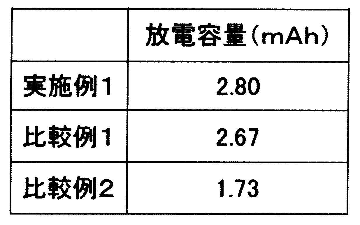
(電池評価:フルセル評価)
前述の黒鉛負極ハーフセル評価と同様に試験を行った。充放電条件は25℃にて、充電速度0.2Cでの4.2V定電流定電圧充電を電流量0.02Cまで行った。次いで放電速度0.2Cで電圧が3.0Vになるまで放電を行った。2サイクル目の放電容量を初期容量とした。
前述の黒鉛負極ハーフセル評価と同様に試験を行った。充放電条件は25℃にて、充電速度0.2Cでの4.2V定電流定電圧充電を電流量0.02Cまで行った。次いで放電速度0.2Cで電圧が3.0Vになるまで放電を行った。2サイクル目の放電容量を初期容量とした。
実施例2
市販の正極シート(活物質:コバルト酸リチウム)と、市販の負極シート(活物質:天然黒鉛)と、セパレーターとしてガラスフィルター(ワットマン社製 GF/F)を、それぞれ円形(正極φ12mm、負極φ14mm、セパレーターφ16mm)に打ち抜いた。宝泉株式会社より購入したCR2032コイン型電池用部品(正極ケース(アルミクラッドSUS304L製)、負極キャップ(SUS316L製)、スペーサー(1mm厚、SUS316L製)、ウェーブワッシャー(SUS316L製)、ガスケット(ポリプロピレン製))および、電解液1、正極、負極、セパレーターを用いてコインセル型リチウムイオン二次電池(フルセル)を作製した。得られたコインセル型リチウムイオン二次電池を、上述のフルセル評価の電池評価条件にて評価を行った。
市販の正極シート(活物質:コバルト酸リチウム)と、市販の負極シート(活物質:天然黒鉛)と、セパレーターとしてガラスフィルター(ワットマン社製 GF/F)を、それぞれ円形(正極φ12mm、負極φ14mm、セパレーターφ16mm)に打ち抜いた。宝泉株式会社より購入したCR2032コイン型電池用部品(正極ケース(アルミクラッドSUS304L製)、負極キャップ(SUS316L製)、スペーサー(1mm厚、SUS316L製)、ウェーブワッシャー(SUS316L製)、ガスケット(ポリプロピレン製))および、電解液1、正極、負極、セパレーターを用いてコインセル型リチウムイオン二次電池(フルセル)を作製した。得られたコインセル型リチウムイオン二次電池を、上述のフルセル評価の電池評価条件にて評価を行った。
比較例3
電解液1の代わりに電解液2を用いた以外は実施例2と同様にしてコインセル型リチウムイオン二次電池を作製し、電池評価を行った。
電解液1の代わりに電解液2を用いた以外は実施例2と同様にしてコインセル型リチウムイオン二次電池を作製し、電池評価を行った。
比較例4
電解液1の代わりに電解液3を用いた以外は実施例2同様にしてコインセル型リチウムイオン二次電池を作製し、電池評価を行った。
電解液1の代わりに電解液3を用いた以外は実施例2同様にしてコインセル型リチウムイオン二次電池を作製し、電池評価を行った。
表2に初期容量を示す。実施例2の放電容量が比較例3及び4よりも大きく、フルオロスルホニルイミド化合物であるLiFSIの効果が確認できた。

(電解液4)
上記のLiFSI0.94gに35℃で溶解したスルホラン(キシダ化学社製)を5.00g加え、1mol/kgのLiFSIのスルホラン溶液(電解液4)を作製した。
上記のLiFSI0.94gに35℃で溶解したスルホラン(キシダ化学社製)を5.00g加え、1mol/kgのLiFSIのスルホラン溶液(電解液4)を作製した。
(電解液5)
スルホランに代えて45℃で溶解したエチルメチルスルホン(東京化成工業社製)を用いた以外は電解液4と同様にして1mol/kgのLiFSIのエチルメチルスルホン溶液(電解液5)を作製した。
スルホランに代えて45℃で溶解したエチルメチルスルホン(東京化成工業社製)を用いた以外は電解液4と同様にして1mol/kgのLiFSIのエチルメチルスルホン溶液(電解液5)を作製した。
(電解液6)
LiTFSIを1.44g用いた以外は電解液4と同様にして1mol/kgのLiTFSIのスルホラン溶液(電解液6)を作製した。
LiTFSIを1.44g用いた以外は電解液4と同様にして1mol/kgのLiTFSIのスルホラン溶液(電解液6)を作製した。
(電解液7)
スルホランに代えて45℃で溶解したエチルメチルスルホン(東京化成工業社製)を用いた以外は電解液6と同様にして1mol/kgのLiTFSIのエチルメチルスルホン溶液(電解液7)を作製した。
スルホランに代えて45℃で溶解したエチルメチルスルホン(東京化成工業社製)を用いた以外は電解液6と同様にして1mol/kgのLiTFSIのエチルメチルスルホン溶液(電解液7)を作製した。
(電池評価:フルセル評価)と同様に0.2Cで5サイクル充放電を行った後、1Cにレートを上げて合計200サイクル充放電を行った。200サイクル後の放電容量を比較した。
実施例3
電解液1の代わりに電解液4を用いた以外は実施例2と同様にしてコインセル型リチウムイオン二次電池を作製し、上述の電池評価の条件にて評価を行った。
電解液1の代わりに電解液4を用いた以外は実施例2と同様にしてコインセル型リチウムイオン二次電池を作製し、上述の電池評価の条件にて評価を行った。
実施例4
電解液4の代わりに電解液5を用いた以外は実施例3と同様にしてコインセル型リチウムイオン二次電池を作製し、評価を行った。
電解液4の代わりに電解液5を用いた以外は実施例3と同様にしてコインセル型リチウムイオン二次電池を作製し、評価を行った。
比較例5
電解液4の代わりに電解液6を用いた以外は実施例3と同様にしてコインセル型リチウムイオン二次電池を作製し、評価を行った。
電解液4の代わりに電解液6を用いた以外は実施例3と同様にしてコインセル型リチウムイオン二次電池を作製し、評価を行った。
比較例6
電解液4の代わりに電解液7を用いた以外は実施例3と同様にしてコインセル型リチウムイオン二次電池を作製し、評価を行った。
電解液4の代わりに電解液7を用いた以外は実施例3と同様にしてコインセル型リチウムイオン二次電池を作製し、評価を行った。
表3に200サイクル後の放電容量を示す。LiFSIを電解質塩に用いた実施例3および4は、LiTFSIを用いた比較例5および比較例6と比較して大きな放電容量を示した。このようにフルオロスルホニルイミド化合物であるLiFSIの効果が長期サイクルにおいても確認された。

実施例5~11と比較例7
LiFSI(日本触媒社製)とLiPF6(森田化学工業社製)を用いて、表4に示した組成の1.0mol/LのLi塩の電解液(溶媒はスルホラン)8種類を調製した。各電解液を用いて、コインセル型リチウムイオン二次電池を作製し、充放電試験装置(ACD-01、アスカ電子株式会社製)を用いて、25℃にて、0.2Cで5サイクルエージングし、その後1Cでサイクル特性を評価した。1Cでの1サイクル目の容量を初期放電容量、100サイクル後の容量を1サイクル目の容量で除した数値を維持率とし、結果を表4に示した。また、0.2Cで5サイクルエージングした後、0.2Cで充電後、5Cで放電したときの放電容量も併せて示す。なお、1.0mol/LのLiPF6を含む電解液に関しては、初期容量が非常に低かったため、1Cサイクル特性及び5C放電は行わなかった。
LiFSI(日本触媒社製)とLiPF6(森田化学工業社製)を用いて、表4に示した組成の1.0mol/LのLi塩の電解液(溶媒はスルホラン)8種類を調製した。各電解液を用いて、コインセル型リチウムイオン二次電池を作製し、充放電試験装置(ACD-01、アスカ電子株式会社製)を用いて、25℃にて、0.2Cで5サイクルエージングし、その後1Cでサイクル特性を評価した。1Cでの1サイクル目の容量を初期放電容量、100サイクル後の容量を1サイクル目の容量で除した数値を維持率とし、結果を表4に示した。また、0.2Cで5サイクルエージングした後、0.2Cで充電後、5Cで放電したときの放電容量も併せて示す。なお、1.0mol/LのLiPF6を含む電解液に関しては、初期容量が非常に低かったため、1Cサイクル特性及び5C放電は行わなかった。

1.0mol/LのLiPF6を含む電解液を用いた電池は初期放電容量が非常に低いが、LiFSIが20mol%含まれている実施例11では、初期容量、維持率ともに、LiFSIが100mol%である実施例5とほぼ同等であった。すなわち、LiFSIが20mol%以上含まれていれば、高いサイクル特性を示すことが確認された。5C放電においては、LiFSI量が多いほど、放電容量が大きいことがわかる。
実施例12~16と比較例8
LiFSI(日本触媒社製)とLiBF4(キシダ化学社製)を用いて、表5に示した組成の1.0mol/LのLi塩の電解液(溶媒はスルホラン)6種類を調製した。各電解液を用いて、コインセル型リチウムイオン二次電池を作製し、充放電試験装置(ACD-01、アスカ電子株式会社製)を用いて、25℃にてサイクル特性を評価した。結果を表5に示した。LiFSIが20mol%以上含まれていれば、高いサイクル特性を示すことがわかる。
LiFSI(日本触媒社製)とLiBF4(キシダ化学社製)を用いて、表5に示した組成の1.0mol/LのLi塩の電解液(溶媒はスルホラン)6種類を調製した。各電解液を用いて、コインセル型リチウムイオン二次電池を作製し、充放電試験装置(ACD-01、アスカ電子株式会社製)を用いて、25℃にてサイクル特性を評価した。結果を表5に示した。LiFSIが20mol%以上含まれていれば、高いサイクル特性を示すことがわかる。

(凝固点の測定)
LiFSI(日本触媒社製)とLiPF6(森田化学工業社製)を用いて、表6に示した組成の1.5mol/LのLi塩の電解液(溶媒はスルホラン)9種類を調製した。DSCを用いて得られた電解液の凝固点を測定した。凝固点が-40℃以下であれば○、-40℃を超える場合は×とした。結果を表6に示した。なお、図2には、LiFSIが1.5mol/Lの電解液(溶媒はスルホラン)のDSCのチャートを示した。
LiFSI(日本触媒社製)とLiPF6(森田化学工業社製)を用いて、表6に示した組成の1.5mol/LのLi塩の電解液(溶媒はスルホラン)9種類を調製した。DSCを用いて得られた電解液の凝固点を測定した。凝固点が-40℃以下であれば○、-40℃を超える場合は×とした。結果を表6に示した。なお、図2には、LiFSIが1.5mol/Lの電解液(溶媒はスルホラン)のDSCのチャートを示した。

(LiFSIの濃度の検討)
LiFSI(日本触媒社製)とスルホラン(キシダ化学社製)を用いて、LiFSIの濃度が、0.8mol/L、1.0mol/L、1.2mol/L、1.5mol/L、2.0mol/Lの5種類の電解液を作製した。得られた電解液を用いてセパレーターとしてセルロースセパレータを用いた以外は実施例2と同様にコインセルを作製した。0.2Cにて5サイクル充放電した後、1Cにてサイクル特性を評価した。初期放電容量と100サイクル後の容量維持率を表7に示した。
また、0.2Cで充電した後、5Cで放電したときの放電電流容量および放電電力容量を表8に示した。なお、測定例15~19における溶媒はスルホラン(SL)であるが、測定例20は、LiPF6を電解質とし、溶媒としてエチレンカーボネート(EC)とエチルメチルカーボネート(EMC)を体積比3:7で用いた例である。


(電池の低温特性評価)
下記組成の電解液を用いてコインセルの低温評価を行った。電池を25℃、0.2Cで充電した後、-20℃で放電を行ったときの放電電力容量及び放電容量を表9に示した。電解液の凍結が観測されなかった測定例22の1.5mol/LのLiFSI/SLでは、放電容量が大きいだけでなく、放電電力容量も大きいことが確認できた。
下記組成の電解液を用いてコインセルの低温評価を行った。電池を25℃、0.2Cで充電した後、-20℃で放電を行ったときの放電電力容量及び放電容量を表9に示した。電解液の凍結が観測されなかった測定例22の1.5mol/LのLiFSI/SLでは、放電容量が大きいだけでなく、放電電力容量も大きいことが確認できた。

(電解液の熱安定性評価)
電解液の熱安定性をDSCにて評価した。測定装置はNETZSCH社製DSC3500、測定用のパンは金蒸着CrNi鋼高圧試料容器(27μl)を用いた。これらの装置を用い、25℃から400℃まで10℃/分で昇温を行った。電解液は電解液4(1mol/kg LiFSIのスルホラン溶液)および1mol/kg LiPF6のEC/EMC(体積比3/7)溶液を用いた。得られたDSCチャートを図3に示す。1mol/kg LiPF6のEC/EMC溶液は250℃付近で吸熱を示したのち、大きな発熱が観測されたのに対し、1mol/kg LiFSIのスルホラン溶液は大きな発熱は観測されなかった。1mol/kg LiFSIのスルホラン溶液は熱安定性の高い電解液であり、電池の熱暴走を起こしにくいと考えられる。
電解液の熱安定性をDSCにて評価した。測定装置はNETZSCH社製DSC3500、測定用のパンは金蒸着CrNi鋼高圧試料容器(27μl)を用いた。これらの装置を用い、25℃から400℃まで10℃/分で昇温を行った。電解液は電解液4(1mol/kg LiFSIのスルホラン溶液)および1mol/kg LiPF6のEC/EMC(体積比3/7)溶液を用いた。得られたDSCチャートを図3に示す。1mol/kg LiPF6のEC/EMC溶液は250℃付近で吸熱を示したのち、大きな発熱が観測されたのに対し、1mol/kg LiFSIのスルホラン溶液は大きな発熱は観測されなかった。1mol/kg LiFSIのスルホラン溶液は熱安定性の高い電解液であり、電池の熱暴走を起こしにくいと考えられる。
(他の溶媒の効果)
1.0mol/LのLiFSI/SL(スルホランの比誘電率は43.3(30℃))系電解液9容量部に対し、下記表に示した溶媒を1容量部添加した。得られた電解液を用いてコインセルを作製し、エージング後、1Cにて25サイクル行った後の放電容量を表10に示した。なお、表中で用いた略語は以下のとおりである。
DOL:1.3-ジオキソラン
DME:ジメトキシエタン
GBL:γ-ブチルラクトン
FEC:フルオロエチレンカーボネート
EC:エチレンカーボネート
PC:プロピレンカーボネート
AcOBu:酢酸ブチル
DMC:ジメチルカーボネート
DEC:ジエチルカーボネート
1.0mol/LのLiFSI/SL(スルホランの比誘電率は43.3(30℃))系電解液9容量部に対し、下記表に示した溶媒を1容量部添加した。得られた電解液を用いてコインセルを作製し、エージング後、1Cにて25サイクル行った後の放電容量を表10に示した。なお、表中で用いた略語は以下のとおりである。
DOL:1.3-ジオキソラン
DME:ジメトキシエタン
GBL:γ-ブチルラクトン
FEC:フルオロエチレンカーボネート
EC:エチレンカーボネート
PC:プロピレンカーボネート
AcOBu:酢酸ブチル
DMC:ジメチルカーボネート
DEC:ジエチルカーボネート
また、放電容量は、以下の基準で評価した。
◎:1.9mAh以上
○:1.4mAh以上、1.9mAh未満
△:0.2mAh以上、1.4mAh未満
×:0.2mAh未満
◎:1.9mAh以上
○:1.4mAh以上、1.9mAh未満
△:0.2mAh以上、1.4mAh未満
×:0.2mAh未満

比誘電率が30以上であるGBL、FEC、EC、PCを添加した電解液を用いた場合に、放電容量が高く、効果があることが確認された。
(オキサラト化合物を含む電解液の検討)
(電解液2-1)
下式で表されるリチウムビス(フルオロスルホニル)イミド;LiFSI(日本触媒社製)0.94gに、35℃で溶解させたスルホラン(キシダ化学社製)を5.00g加え、1mol/kgのLiFSIのスルホラン溶液(電解液2-1)を調製した。

(電解液2-1)
下式で表されるリチウムビス(フルオロスルホニル)イミド;LiFSI(日本触媒社製)0.94gに、35℃で溶解させたスルホラン(キシダ化学社製)を5.00g加え、1mol/kgのLiFSIのスルホラン溶液(電解液2-1)を調製した。
(電解液2-2)
電解液2-1と同様に1mol/kgのLiFSIのスルホラン溶液を調製し、この溶液に対して、0.100gのリチウムビス(オキサラト)ボレート(下記)(LiBOB)を加え、電解液2-2を調製した。
電解液2-1と同様に1mol/kgのLiFSIのスルホラン溶液を調製し、この溶液に対して、0.100gのリチウムビス(オキサラト)ボレート(下記)(LiBOB)を加え、電解液2-2を調製した。

(電解液2-3)
電解液2-1と同様に1mol/kgのLiFSIのスルホラン溶液を調製し、この溶液に対して、0.100gのリチウムジフルオロ(オキサラト)ボレート(下記)(LiDFOB)を加え、電解液2-3を調製した。
電解液2-1と同様に1mol/kgのLiFSIのスルホラン溶液を調製し、この溶液に対して、0.100gのリチウムジフルオロ(オキサラト)ボレート(下記)(LiDFOB)を加え、電解液2-3を調製した。

(電解液2-4)
電解液2-1と同様に1mol/kgのLiFSIのスルホラン溶液を調製し、この溶液に対して、0.100gのビニレンカーボネート(VC)を加え、電解液2-4を調製した。
電解液2-1と同様に1mol/kgのLiFSIのスルホラン溶液を調製し、この溶液に対して、0.100gのビニレンカーボネート(VC)を加え、電解液2-4を調製した。
(正極シート)
正極活物質(LiCoO2)、導電助剤1(アセチレンブラック、AB)、導電助剤2(グラファイト)及び結着剤(ポリフッ化ビニリデン、PVdF)を92:2:2:4の質量比で混合し、N-メチルピロリドンに分散させて正極合剤スラリーとし、アルミニウム箔(正極集電体)上に塗工し、乾燥して、正極シートを作製した。
正極活物質(LiCoO2)、導電助剤1(アセチレンブラック、AB)、導電助剤2(グラファイト)及び結着剤(ポリフッ化ビニリデン、PVdF)を92:2:2:4の質量比で混合し、N-メチルピロリドンに分散させて正極合剤スラリーとし、アルミニウム箔(正極集電体)上に塗工し、乾燥して、正極シートを作製した。
(負極シート)
負極活物質(天然黒鉛)、導電助剤(炭素繊維、「VGCF(登録商標)」、昭和電工社製)、及び結着剤(ポリフッ化ビニリデン、PVdF)を95.7:0.5:3.8の質量比で混合した負極合剤スラリーを銅箔(負極集電体)上に塗工し、乾燥して、負極シートを作製した。
負極活物質(天然黒鉛)、導電助剤(炭素繊維、「VGCF(登録商標)」、昭和電工社製)、及び結着剤(ポリフッ化ビニリデン、PVdF)を95.7:0.5:3.8の質量比で混合した負極合剤スラリーを銅箔(負極集電体)上に塗工し、乾燥して、負極シートを作製した。
(コインセル型リチウムイオン二次電池の作製)
正極シート、負極シートおよびガラス繊維ろ紙(ワットマン社製、GF/F)を、それぞれ円形(正極φ12mm、負極φ14mm、ガラス繊維ろ紙φ16mm)に打ち抜いた。宝泉株式会社より購入したCR2032コイン型電池用部品(正極ケース(アルミクラッドSUS304L製)、負極キャップ(SUS316L製)、スペーサー(1mm厚、SUS316L製)、ウェーブワッシャー(SUS316L製)、ガスケット(ポリプロピレン製))を用いてコインセル型リチウムイオン二次電池を作製した。具体的には、ガスケットを装着した負極キャップ、ウェーブワッシャー、スペーサー、負極シート(負極の銅箔側がスペーサーと対向するように設置)、セパレーターをこの順で重ねた後、100μLの非水電解液をポリエチレン製のセパレーターに含浸させた。次いで、正極合剤塗布面が負極活物質層側と対向するように正極シートを設置し、その上に正極ケースを重ね、カシメ機でかしめることによりコインセル型リチウムイオン二次電池を作製した。
正極シート、負極シートおよびガラス繊維ろ紙(ワットマン社製、GF/F)を、それぞれ円形(正極φ12mm、負極φ14mm、ガラス繊維ろ紙φ16mm)に打ち抜いた。宝泉株式会社より購入したCR2032コイン型電池用部品(正極ケース(アルミクラッドSUS304L製)、負極キャップ(SUS316L製)、スペーサー(1mm厚、SUS316L製)、ウェーブワッシャー(SUS316L製)、ガスケット(ポリプロピレン製))を用いてコインセル型リチウムイオン二次電池を作製した。具体的には、ガスケットを装着した負極キャップ、ウェーブワッシャー、スペーサー、負極シート(負極の銅箔側がスペーサーと対向するように設置)、セパレーターをこの順で重ねた後、100μLの非水電解液をポリエチレン製のセパレーターに含浸させた。次いで、正極合剤塗布面が負極活物質層側と対向するように正極シートを設置し、その上に正極ケースを重ね、カシメ機でかしめることによりコインセル型リチウムイオン二次電池を作製した。
(電池評価:フルセル評価)
充放電試験装置(ACD-01、アスカ電子株式会社製)を使用して、温度25℃の環境下、コインセル型リチウムイオン二次電池の放電容量測定を行った。充放電条件は、充電速度0.2Cでの4.35V定電流定電圧充電を電流量0.02Cまで行い、次いで放電速度0.2Cで電圧が3.0Vになるまで放電を行った。この0.2Cでの充放電を5回繰り返したのち、充電速度1C、放電速度1Cにした以外は0.2Cの時と同じ条件で300回充放電を繰り返した。表11に300サイクル後の放電容量を示す。
充放電試験装置(ACD-01、アスカ電子株式会社製)を使用して、温度25℃の環境下、コインセル型リチウムイオン二次電池の放電容量測定を行った。充放電条件は、充電速度0.2Cでの4.35V定電流定電圧充電を電流量0.02Cまで行い、次いで放電速度0.2Cで電圧が3.0Vになるまで放電を行った。この0.2Cでの充放電を5回繰り返したのち、充電速度1C、放電速度1Cにした以外は0.2Cの時と同じ条件で300回充放電を繰り返した。表11に300サイクル後の放電容量を示す。

(電池の安全性)
DSCの測定
DSCの測定装置および測定条件は、電解液の熱安定性評価と同様にした。電解液2-2および1.2mol/LのLiPF6のEC/EMC(体積比3/7)溶液を用いて、実施例2-1と同様にしてコインセルを作製し、0.2Cでの充放電を5回繰り返した後、0.2Cで4.35Vまで充電した。得られた電池をグローブボックスで解体し、正極および負極を約2mgずつ削り取り、それぞれをDSCのパンに詰め、電解液を2μl添加した。パンを封止後、DSCを測定した。正極および負極での発熱量を表12に示す。正極、負極とも本発明の電解液を用いることにより、充電状態の正極および負極との反応による発熱を大幅に減少することが確認された。本発明の電解液は電池の熱暴走を抑制できるといえる。

(特定のR値を有する黒鉛の検討)
実施例で用いた測定方法は、以下のとおりである。
ラマンスペクトル測定
JASCO NR-3100(日本分光社製)を用いて、以下の条件にてラマンスペクトルを測定した。得られたラマンスペクトルについて、1580cm-1付近のピーク強度をIG、1360cm-1付近のピーク強度をIDとし、強度比R(R=ID/IG)を算出した。
レーザー波長:532nm
露光時間:10秒×5回
中心波数:1400cm-1
スリット:φ0.05mm
減光器:オープン
対物レンズ:20倍
データ間隔:1cm-1
スムージング処理:ベースライン補正(872cm-1~1873cm-1の間で直線補正)スムージング処理、単純平均移動(コンボリューション幅 5)
(電解液3-1の調製)
LiPF6(キシダ化学社製)を1.52gのエチレンカーボネート(EC)とエチルメチルカーボネート(EMC)の混合溶媒(EC:EMC=3:7(体積比)キシダ化学社製)に溶解させ、1mol/LのLiPF6が含まれた電解液3-1を得た。
LiPF6(キシダ化学社製)を1.52gのエチレンカーボネート(EC)とエチルメチルカーボネート(EMC)の混合溶媒(EC:EMC=3:7(体積比)キシダ化学社製)に溶解させ、1mol/LのLiPF6が含まれた電解液3-1を得た。
(電解液3-2の調製)
リチウムビス(フルオロスルホニル)イミド(LiFSI:日本触媒社製)2.805gに、35℃で溶解したスルホラン(キシダ化学社製)を加え、1.5mol/Lのスルホラン溶液(電解液3-2)を得た。
リチウムビス(フルオロスルホニル)イミド(LiFSI:日本触媒社製)2.805gに、35℃で溶解したスルホラン(キシダ化学社製)を加え、1.5mol/Lのスルホラン溶液(電解液3-2)を得た。
(負極シートの作製)
負極活物質及び結着剤(ポリフッ化ビニリデン、PVdF)を92:8の質量比で混合した負極合剤スラリーを銅箔(負極集電体)上に塗工し、乾燥して、負極シートを作製した。負極活物質としては以下の黒鉛を用いた。
実施例3-1:CGB10(日本黒鉛社製)
実施例3-2:SLP50(Timcal社製)
実施例3-3:SMG(日立化成社製)
参考例3-1:MAGE(日立化成社製)
負極活物質及び結着剤(ポリフッ化ビニリデン、PVdF)を92:8の質量比で混合した負極合剤スラリーを銅箔(負極集電体)上に塗工し、乾燥して、負極シートを作製した。負極活物質としては以下の黒鉛を用いた。
実施例3-1:CGB10(日本黒鉛社製)
実施例3-2:SLP50(Timcal社製)
実施例3-3:SMG(日立化成社製)
参考例3-1:MAGE(日立化成社製)
(コインセル型リチウムイオン二次電池の作製)
負極シート、リチウム箔及び、ガラスフィルター(ワットマン社製 GF/F)を、それぞれ円形(負極φ12mm、リチウム箔φ14mm、ガラスフィルターφ16mm)に打ち抜いた。宝泉株式会社より購入したCR2032コイン型電池用部品(正極ケース(アルミクラッドSUS304L製)、負極キャップ(SUS316L製)、スペーサー(1mm厚、SUS316L製)、ウェーブワッシャー(SUS316L製)、ガスケット(ポリプロピレン製))を用いてコインセル型リチウムイオン二次電池を作製した。具体的には、ガスケットを装着した負極キャップ、ウェーブワッシャー、スペーサー、リチウム箔、セパレーターをこの順で重ねた後、電解液1または電解液2をガラスフィルターに含浸させた。次いで、負極シートを設置し、その上に正極ケースを重ね、カシメ機でかしめることによりコインセル型リチウムイオン二次電池のハーフセルを作製した。
負極シート、リチウム箔及び、ガラスフィルター(ワットマン社製 GF/F)を、それぞれ円形(負極φ12mm、リチウム箔φ14mm、ガラスフィルターφ16mm)に打ち抜いた。宝泉株式会社より購入したCR2032コイン型電池用部品(正極ケース(アルミクラッドSUS304L製)、負極キャップ(SUS316L製)、スペーサー(1mm厚、SUS316L製)、ウェーブワッシャー(SUS316L製)、ガスケット(ポリプロピレン製))を用いてコインセル型リチウムイオン二次電池を作製した。具体的には、ガスケットを装着した負極キャップ、ウェーブワッシャー、スペーサー、リチウム箔、セパレーターをこの順で重ねた後、電解液1または電解液2をガラスフィルターに含浸させた。次いで、負極シートを設置し、その上に正極ケースを重ね、カシメ機でかしめることによりコインセル型リチウムイオン二次電池のハーフセルを作製した。
(電池評価:フルセル評価)
充放電試験装置(ACD-01、アスカ電子株式会社製)を使用して、温度25℃の環境下、コインセル型リチウムイオン二次電池の放電容量測定を行った。充放電条件は、充電速度0.2Cでの2.0V定電流定電圧充電を行い、次いで放電速度0.2Cで電圧が0.05Vになるまで放電を行った。3サイクル目の放電容量を記した。結果を表13に示す。
充放電試験装置(ACD-01、アスカ電子株式会社製)を使用して、温度25℃の環境下、コインセル型リチウムイオン二次電池の放電容量測定を行った。充放電条件は、充電速度0.2Cでの2.0V定電流定電圧充電を行い、次いで放電速度0.2Cで電圧が0.05Vになるまで放電を行った。3サイクル目の放電容量を記した。結果を表13に示す。

本発明の非水電解液は、非水電解液二次電池の非水電解液として有用であり、本発明の非水電解液二次電池は、スマートフォンやパーソナルコンピューター用の電源、自動車用電源等として有用である。
Claims (7)
- 一般式(1)で表されるフルオロスルホニルイミド化合物(式(1)中、Mはアルカリ金属イオンを表し、Xはフッ素原子または炭素数1~6のフルオロアルキル基を表す)と、一般式(2)で表されるスルホン化合物(R1及びR2は、それぞれ同一もしくは独立して炭化水素基を表し、互いに結合して環状構造を形成していてもよい。)を含むことを特徴とする非水電解液。


- 上記スルホン化合物が、環状スルホン化合物であることを特徴とする請求項1に記載の非水電解液。
- 上記スルホン化合物の濃度が、非水電解液中、30~95質量%であることを特徴とする請求項1又は2に記載の非水電解液。
- 上記非水電解液が、さらに、下記一般式(3)で表されるオキサラト化合物を含むことを特徴とする請求項1~3のいずれかに記載の非水電解液。

(一般式(3)中、M1はBまたはP、Aa+は金属イオン、水素イオン、又はオニウムイオン、aは1~3、bは1~3、pはb/a、qは1~3、mは0~4、nは0または1をそれぞれ表し、R3はフッ素、シアノ基又はC1~C10のフッ素化アルキル基、R4はC1~C10のアルキレン基またはC1~C10のハロゲン化アルキレン基、X1、X2はそれぞれ独立でOまたはSを表す。) - 請求項1~4のいずれかに記載の非水電解液を用いたことを特徴とする非水電解液二次電池。
- 負極が負極活物質として炭素材料を含むことを特徴とする請求項5に記載の非水電解液二次電池。
- 上記炭素材料が、波長532nmのレーザーで励起させたときのラマンスペクトルの強度比R(1350cm-1のピーク強度/1580cm-1のピーク強度)が0.1≦R≦0.5である炭素材料であることを特徴とする請求項6に記載の非水電解液二次電池。
Applications Claiming Priority (8)
| Application Number | Priority Date | Filing Date | Title |
|---|---|---|---|
| JP2015-123619 | 2015-06-19 | ||
| JP2015123619 | 2015-06-19 | ||
| JP2015233334 | 2015-11-30 | ||
| JP2015-233334 | 2015-11-30 | ||
| JP2016-044404 | 2016-03-08 | ||
| JP2016044404 | 2016-03-08 | ||
| JP2016104425A JP6646522B2 (ja) | 2016-05-25 | 2016-05-25 | 非水電解液二次電池 |
| JP2016-104425 | 2016-05-25 |
Publications (1)
| Publication Number | Publication Date |
|---|---|
| WO2016204278A1 true WO2016204278A1 (ja) | 2016-12-22 |
Family
ID=57546238
Family Applications (1)
| Application Number | Title | Priority Date | Filing Date |
|---|---|---|---|
| PCT/JP2016/068123 WO2016204278A1 (ja) | 2015-06-19 | 2016-06-17 | 非水電解液およびそれを用いた非水電解液二次電池 |
Country Status (1)
| Country | Link |
|---|---|
| WO (1) | WO2016204278A1 (ja) |
Cited By (5)
| Publication number | Priority date | Publication date | Assignee | Title |
|---|---|---|---|---|
| JP2019046614A (ja) * | 2017-08-31 | 2019-03-22 | 三菱ケミカル株式会社 | ナトリウムイオン二次電池用非水系電解液及びナトリウムイオン二次電池 |
| WO2019150901A1 (ja) | 2018-01-31 | 2019-08-08 | パナソニックIpマネジメント株式会社 | 非水電解質二次電池、電解液及び非水電解質二次電池の製造方法 |
| WO2020179126A1 (ja) * | 2019-03-05 | 2020-09-10 | 株式会社日立製作所 | 非水電解液、半固体電解質層、二次電池用シート及び二次電池 |
| WO2021123408A1 (en) * | 2019-12-20 | 2021-06-24 | Umicore | Electrolyte for li secondary batteries |
| US11267707B2 (en) | 2019-04-16 | 2022-03-08 | Honeywell International Inc | Purification of bis(fluorosulfonyl) imide |
Citations (7)
| Publication number | Priority date | Publication date | Assignee | Title |
|---|---|---|---|---|
| JP2000077098A (ja) * | 1998-08-28 | 2000-03-14 | Yuasa Corp | 非水電解質電池 |
| JP2002190301A (ja) * | 2000-12-21 | 2002-07-05 | Nissan Motor Co Ltd | 非水溶媒二次電池の電極炭素材料およびその製造方法 |
| JP2006228505A (ja) * | 2005-02-16 | 2006-08-31 | Hitachi Chem Co Ltd | リチウムイオン二次電池負極用黒鉛粒子及びその製造法、並びにそれを用いたリチウムイオン二次電池用負極及びリチウムイオン二次電池 |
| JP2010225498A (ja) * | 2009-03-25 | 2010-10-07 | Panasonic Corp | 有機電解液電池 |
| JP2012190699A (ja) * | 2011-03-11 | 2012-10-04 | Mitsubishi Chemicals Corp | 非水系電解液及びそれを用いた非水系電解液二次電池 |
| WO2014080870A1 (ja) * | 2012-11-20 | 2014-05-30 | 日本電気株式会社 | リチウムイオン二次電池 |
| WO2014157591A1 (ja) * | 2013-03-27 | 2014-10-02 | 三菱化学株式会社 | 非水系電解液及びそれを用いた非水系電解液電池 |
-
2016
- 2016-06-17 WO PCT/JP2016/068123 patent/WO2016204278A1/ja active Application Filing
Patent Citations (7)
| Publication number | Priority date | Publication date | Assignee | Title |
|---|---|---|---|---|
| JP2000077098A (ja) * | 1998-08-28 | 2000-03-14 | Yuasa Corp | 非水電解質電池 |
| JP2002190301A (ja) * | 2000-12-21 | 2002-07-05 | Nissan Motor Co Ltd | 非水溶媒二次電池の電極炭素材料およびその製造方法 |
| JP2006228505A (ja) * | 2005-02-16 | 2006-08-31 | Hitachi Chem Co Ltd | リチウムイオン二次電池負極用黒鉛粒子及びその製造法、並びにそれを用いたリチウムイオン二次電池用負極及びリチウムイオン二次電池 |
| JP2010225498A (ja) * | 2009-03-25 | 2010-10-07 | Panasonic Corp | 有機電解液電池 |
| JP2012190699A (ja) * | 2011-03-11 | 2012-10-04 | Mitsubishi Chemicals Corp | 非水系電解液及びそれを用いた非水系電解液二次電池 |
| WO2014080870A1 (ja) * | 2012-11-20 | 2014-05-30 | 日本電気株式会社 | リチウムイオン二次電池 |
| WO2014157591A1 (ja) * | 2013-03-27 | 2014-10-02 | 三菱化学株式会社 | 非水系電解液及びそれを用いた非水系電解液電池 |
Cited By (10)
| Publication number | Priority date | Publication date | Assignee | Title |
|---|---|---|---|---|
| JP2019046614A (ja) * | 2017-08-31 | 2019-03-22 | 三菱ケミカル株式会社 | ナトリウムイオン二次電池用非水系電解液及びナトリウムイオン二次電池 |
| WO2019150901A1 (ja) | 2018-01-31 | 2019-08-08 | パナソニックIpマネジメント株式会社 | 非水電解質二次電池、電解液及び非水電解質二次電池の製造方法 |
| WO2020179126A1 (ja) * | 2019-03-05 | 2020-09-10 | 株式会社日立製作所 | 非水電解液、半固体電解質層、二次電池用シート及び二次電池 |
| JP2020145054A (ja) * | 2019-03-05 | 2020-09-10 | 株式会社日立製作所 | 非水電解液、半固体電解質層、二次電池用シート及び二次電池 |
| KR20210087515A (ko) * | 2019-03-05 | 2021-07-12 | 가부시키가이샤 히타치세이사쿠쇼 | 비수 전해액, 반고체 전해질층, 이차 전지용 시트 및 이차 전지 |
| CN113169379A (zh) * | 2019-03-05 | 2021-07-23 | 株式会社日立制作所 | 非水电解液、半固体电解质层、二次电池用片材和二次电池 |
| JP7270210B2 (ja) | 2019-03-05 | 2023-05-10 | 株式会社日立製作所 | 非水電解液、半固体電解質層、二次電池用シート及び二次電池 |
| KR102610616B1 (ko) * | 2019-03-05 | 2023-12-07 | 가부시키가이샤 히타치세이사쿠쇼 | 비수 전해액, 반고체 전해질층, 이차 전지용 시트 및 이차 전지 |
| US11267707B2 (en) | 2019-04-16 | 2022-03-08 | Honeywell International Inc | Purification of bis(fluorosulfonyl) imide |
| WO2021123408A1 (en) * | 2019-12-20 | 2021-06-24 | Umicore | Electrolyte for li secondary batteries |
Similar Documents
| Publication | Publication Date | Title |
|---|---|---|
| EP2958183B1 (en) | Electrolyte solution and lithium ion secondary battery provided with same | |
| US10177413B2 (en) | Lithium ion secondary battery | |
| EP2833468B1 (en) | Non-aqueous electrolyte solution for secondary batteries, and lithium-ion secondary battery | |
| JP6647877B2 (ja) | 非水電解液およびそれを用いた非水電解液二次電池 | |
| JP2003151623A (ja) | 非水系二次電池 | |
| KR101322500B1 (ko) | 비수 전해질 조성물 및 비수 전해질 2차 전지 | |
| JP6715096B2 (ja) | 非水電解液およびそれを用いた非水電解液二次電池 | |
| US10749215B2 (en) | Electrolyte solution for secondary battery and secondary battery | |
| WO2016204278A1 (ja) | 非水電解液およびそれを用いた非水電解液二次電池 | |
| WO2020054863A1 (ja) | 非水系電解液及び非水系二次電池 | |
| JP6018820B2 (ja) | リチウム二次電池用非水電解液及びこれを備えたリチウム二次電池 | |
| KR20210011441A (ko) | 비수계 전해액 및 비수계 이차 전지 | |
| CN113841280A (zh) | 电解质组合物、溶剂组合物、非水电解液及其用途 | |
| JP6785148B2 (ja) | 非水電解液およびそれを用いた非水電解液二次電池 | |
| KR20210011342A (ko) | 리튬 이차전지 | |
| JP2023146966A (ja) | 非水系二次電池及びその製造方法 | |
| JP2015062154A (ja) | リチウムイオン二次電池 | |
| JP5727985B2 (ja) | 電池用電極及びこれを用いた電池 | |
| JP6646522B2 (ja) | 非水電解液二次電池 | |
| CN114287077A (zh) | 非水系电解液、电池包和电池包的制造方法 | |
| JP7060777B2 (ja) | 蓄電デバイス用非水電解液 | |
| WO2022065198A1 (ja) | 非水電解液、二次電池及びその製造方法 | |
| JP7366845B2 (ja) | 非水系電解液及び非水系二次電池 | |
| JP6315775B2 (ja) | リチウムイオン二次電池 | |
| WO2024106166A1 (ja) | 非水電解液二次電池 |
Legal Events
| Date | Code | Title | Description |
|---|---|---|---|
| 121 | Ep: the epo has been informed by wipo that ep was designated in this application |
Ref document number: 16811752 Country of ref document: EP Kind code of ref document: A1 |
|
| NENP | Non-entry into the national phase |
Ref country code: DE |
|
| 122 | Ep: pct application non-entry in european phase |
Ref document number: 16811752 Country of ref document: EP Kind code of ref document: A1 |