WO2016204146A1 - 多層積層フィルム - Google Patents
多層積層フィルム Download PDFInfo
- Publication number
- WO2016204146A1 WO2016204146A1 PCT/JP2016/067679 JP2016067679W WO2016204146A1 WO 2016204146 A1 WO2016204146 A1 WO 2016204146A1 JP 2016067679 W JP2016067679 W JP 2016067679W WO 2016204146 A1 WO2016204146 A1 WO 2016204146A1
- Authority
- WO
- WIPO (PCT)
- Prior art keywords
- film
- layer
- multilayer
- resin
- laminated film
- Prior art date
- Legal status (The legal status is an assumption and is not a legal conclusion. Google has not performed a legal analysis and makes no representation as to the accuracy of the status listed.)
- Ceased
Links
Images


Classifications
-
- B—PERFORMING OPERATIONS; TRANSPORTING
- B32—LAYERED PRODUCTS
- B32B—LAYERED PRODUCTS, i.e. PRODUCTS BUILT-UP OF STRATA OF FLAT OR NON-FLAT, e.g. CELLULAR OR HONEYCOMB, FORM
- B32B7/00—Layered products characterised by the relation between layers; Layered products characterised by the relative orientation of features between layers, or by the relative values of a measurable parameter between layers, i.e. products comprising layers having different physical, chemical or physicochemical properties; Layered products characterised by the interconnection of layers
- B32B7/02—Physical, chemical or physicochemical properties
- B32B7/027—Thermal properties
-
- G—PHYSICS
- G02—OPTICS
- G02B—OPTICAL ELEMENTS, SYSTEMS OR APPARATUS
- G02B5/00—Optical elements other than lenses
- G02B5/30—Polarising elements
-
- G—PHYSICS
- G02—OPTICS
- G02F—OPTICAL DEVICES OR ARRANGEMENTS FOR THE CONTROL OF LIGHT BY MODIFICATION OF THE OPTICAL PROPERTIES OF THE MEDIA OF THE ELEMENTS INVOLVED THEREIN; NON-LINEAR OPTICS; FREQUENCY-CHANGING OF LIGHT; OPTICAL LOGIC ELEMENTS; OPTICAL ANALOGUE/DIGITAL CONVERTERS
- G02F1/00—Devices or arrangements for the control of the intensity, colour, phase, polarisation or direction of light arriving from an independent light source, e.g. switching, gating or modulating; Non-linear optics
- G02F1/01—Devices or arrangements for the control of the intensity, colour, phase, polarisation or direction of light arriving from an independent light source, e.g. switching, gating or modulating; Non-linear optics for the control of the intensity, phase, polarisation or colour
- G02F1/13—Devices or arrangements for the control of the intensity, colour, phase, polarisation or direction of light arriving from an independent light source, e.g. switching, gating or modulating; Non-linear optics for the control of the intensity, phase, polarisation or colour based on liquid crystals, e.g. single liquid crystal display cells
- G02F1/133—Constructional arrangements; Operation of liquid crystal cells; Circuit arrangements
- G02F1/1333—Constructional arrangements; Manufacturing methods
- G02F1/1335—Structural association of cells with optical devices, e.g. polarisers or reflectors
Definitions
- the present invention relates to a multilayer laminated film and an optical film using the same.
- a liquid crystal display device using a liquid crystal display panel as a display element is rapidly expanding its use as a thin display device such as a liquid crystal television, a liquid crystal monitor, and a personal computer.
- a liquid crystal television such as a liquid crystal television, a liquid crystal monitor, and a personal computer.
- the market for LCD TVs and mobile phones is growing significantly.
- a polarizing plate is always used for a liquid crystal display device, but a polarizer protective film is generally used for the polarizing plate, and as the film, triacetyl cellulose (hereinafter referred to as “highly transparent” and optical isotropy) is used.
- TAC triacetyl cellulose
- the TAC film cannot be said to exhibit sufficient performance in terms of chemical resistance, scratch resistance, and the like, and as the liquid crystal display in recent years becomes larger and thinner, Strength, dimensional stability, high moisture permeability, and the like are issues.
- Patent Documents 1 and 2 In order to solve the above problems, other amorphous resins such as cycloolefin polymers and acrylics have been studied in place of the TAC film (Patent Documents 1 and 2). There is a problem that costs are increased because no general-purpose resin is used.
- PET film a polyethylene terephthalate (hereinafter referred to as PET) film is often used because it has low moisture permeability compared to a TAC film, is excellent in handling, and can be reduced in cost because it is a general-purpose resin.
- a film made of a crystalline resin such as a PET film is generally subjected to a treatment such as uniaxial stretching or biaxial stretching, but the retardation may be increased by the stretching treatment.
- phase difference of the film When the phase difference of the film is in a specific range, there is no effect on the visibility under natural light (non-polarized light), but there is a problem that rainbow unevenness and interference color can be seen when viewed through a polarizer such as polarized sunglasses. .
- polarizer such as polarized sunglasses.
- the unstretched state there is a merit that generation of light interference color can be suppressed, but in addition to the problem that the strength is remarkably reduced, it is used for a protective film for a polarizing plate in recent years where a demand for thinning is strong Was not appropriate.
- Patent Document 4 a retardation film that uses a multilayer structure and uses structural birefringence and molecular orientation birefringence and has a strict requirement for retardation accuracy compared to a polarizer protective film.
- the average layer thickness is very thin, 30 nm or less, and a special resin combination of an amorphous resin having negative optical anisotropy and an isotropic amorphous resin, and Since the thickness and the total number of layers are also very large, there has been a problem of high material and manufacturing costs. That is, even if the optical performance is satisfied, the characteristics are not different from those of the conventional amorphous resin, and the thin film, low cost, low moisture permeability, and dimensional stability are not satisfied.
- the problem to be solved by the present invention is a multilayer laminated film having a biaxially oriented A layer and a weakly oriented B layer, and the respective phase differences of the A layer and the B layer are subtracted from each other.
- a display device such as a large-screen liquid crystal display as a polarizer protective film
- a high-quality display is obtained with little change in contrast, rainbow unevenness and interference color.
- the present invention is as follows.
- [1] A multilayer laminated film in which a layer A made of a biaxially orientable crystalline resin a and a layer B made of a resin b having lower crystallinity than a are alternately laminated, and the surface layer Multilayers characterized in that the total phase difference Re of the multilayer laminated film satisfies the expressions (1) and (2), where Re (k) is the phase difference in the kth layer from the first layer and n is the total number of layers.
- Re (k) is the phase difference in the kth layer from the first layer
- n is the total number of layers.
- a multilayer laminate film in which at least three or more layers A are made of a biaxially orientable crystalline resin a and a B layer is made of a resin b having lower crystallinity than the crystalline resin a.
- the refractive index in the direction giving the maximum refractive index in the in-plane direction is Nx (1)
- the refractive index in the direction perpendicular to it is Ny (1)
- the resin b is a multilayer laminated film containing one or more components selected from any of the component groups consisting of isophthalic acid, spiroglycol, isosorbide, fluorene, bisphenol A, and cyclohexyne dimethanol component.
- the crystalline resin a is preferably a multilayer laminated film selected from polyethylene terephthalate, polyethylene naphthalate, and polybutylene terephthalate.
- the present invention Since the present invention has a low retardation, it can be used for a retardation film, a polarizer protective film having a retardation function, a substrate film for a touch panel, and the like.
- a retardation film a polarizer protective film having a retardation function
- a substrate film for a touch panel and the like.
- there is little retardation in the width direction and unevenness in the orientation angle there is little change in contrast, rainbow unevenness, and interference color when mounted on a display device such as a large-screen liquid crystal display as a polarizer protective film. The effect which can obtain a simple display is produced.
- FIG. 1 is a schematic diagram showing a light transmitting direction when different resins are stacked.
- FIG. 2 is a schematic diagram showing a light transmitting direction when the same resin is stacked.
- FIG. 3A is a schematic view when two single film films are stacked.
- FIG. 3B is a schematic diagram showing the relationship of the refractive index ellipsoid when two single film films are stacked.
- FIG. 4A is a distribution of refractive index ellipsoids in the width direction of the multilayer laminated film. (B) Distribution of the refractive index ellipsoid of the multilayer laminated film in the width direction when two multilayer laminated films are stacked.
- FIG. 1 is a schematic diagram showing a light transmitting direction when different resins are stacked.
- FIG. 2 is a schematic diagram showing a light transmitting direction when the same resin is stacked.
- FIG. 3A is a schematic view when two single film films are stacked.
- FIG. 3B is a
- FIG. 5A is a schematic diagram of phase difference subtraction using one full-width multilayer laminated film.
- FIG.5 (b) is a schematic diagram of the addition of the phase difference using one full width multilayer laminated film.
- 6 is an orientation distribution of the A layer and the B layer of the multilayer laminated film of Example 11.
- FIG. 7A shows the retardation distribution in the film width direction in the multilayer laminated film of Example 13.
- FIG. 7B shows the orientation angle distribution in the film width direction of the multilayer laminated film of Example 13.
- FIG. 8A shows a retardation distribution in the film width direction when the MD direction of the multilayer laminated film of Example 13 is reversed and bonded together.
- FIG. 8B is a retardation distribution in the film width direction when two multilayer laminated films of Example 13 are bonded together with the same MD direction.
- the in-plane retardation of the film or layer is a value represented by (Nx ⁇ Ny) ⁇ d unless otherwise specified.
- Nx represents a refractive index in a direction (in-plane direction) perpendicular to the thickness direction of the film or layer and giving the maximum refractive index.
- Ny represents the refractive index in the in-plane direction of the film or layer and perpendicular to the Nx direction.
- d represents the film thickness of the film or layer.
- the phase difference measurement wavelength is 590 nm.
- the phase difference can be measured using a commercially available phase difference measuring apparatus (for example, “KOBRA-21ADH” manufactured by Oji Scientific Instruments, “WPA-micro” manufactured by Photonic Lattice) or the Senalmon method.
- the multilayer laminated film of the present invention is a film in which crystalline resin a and resin b are alternately laminated at least three layers.
- the term “alternately laminated” here means that layers made of different resins are laminated in a regular arrangement in the thickness direction. For example, when the layers are made of crystalline resin a and resin b, each layer is designated as A layer. , B layers are stacked in a regular arrangement such as A (BA) n (n is a natural number).
- the outermost layer of this multilayer laminated film may have a C layer made of resin c and may have a configuration such as C ⁇ A (BA) n ⁇ C.
- the total retardation Re of the multilayer laminated film satisfies the following formula (1).
- k is a natural number.
- phase difference Re of the entire multilayer laminated film obtained using a commercially available measuring device is smaller than the value obtained by individually measuring and calculating the phase difference of each layer and adding the respective phase differences. It means to become.
- a film obtained by peeling each layer into a single film may be measured with a commercially available measuring device, or the surface layer as disclosed in JP-A-2014-149346. May be measured after polishing each with a plastic polishing cloth to form each layer as a single layer.
- Re (1) is the phase difference of the outermost layer of the multilayer laminated film
- Nx (1) and Ny (1) are the refractive index in the direction giving the maximum refractive index in the in-plane direction of the outermost layer and perpendicular thereto.
- the refractive index in the direction, d (1) is the thickness of the outermost layer
- D ′ is the total thickness of the layers using the same resin as the outermost layer in the multilayer laminated film. This equation will be described next.
- the refractive index in the in-plane direction can be obtained by using a spectroscopic ellipsometer, spectrophotometer, prism coupler, Abbe refractometer or the like.
- the phase difference of the outermost layer can be easily calculated.
- the inner layer resin is the same resin as the outermost layer and the film forming conditions are the same, the birefringence of the outermost layer and the inner layer is assumed to be the same, and the phase difference of the inner layer can be estimated. Therefore, the phase difference can be measured for the same resin as the outermost layer of the multilayer laminated film.
- the added value of the retardation of the layer made of the same resin as the outermost layer is larger than the total retardation Re of the multilayer laminated film, the formula (1) of claim 1 is already satisfied. That is, the retardation of the resin layer different from the outermost layer means that the effect of subtracting the retardation is acting on the multilayer laminated film.
- the refractive index in the in-plane direction of the A layer is Nx (a) and Ny (a), respectively
- the refractive index in the in-plane direction of the B layer is Nx (b) and Ny (b )
- the birefringence of the A layer is (Nx (a) ⁇ Ny (a))
- the birefringence of the B layer is (Nx (b) ⁇ Ny (b)).
- the B layer is the same resin as the A layer and the layer is assumed to be A ′, the result is as shown in FIG.
- d means the thickness of the two-layer film. Therefore, it is obvious that the total retardation Re of the multilayer laminated film is an added value of the retardation of each film. Therefore, generally, the sum of retardation obtained from the refractive index and thickness of each layer and the retardation of the laminated film measured using a commercially available measuring device should be the same value.
- the total of the multilayer laminated film is more than the value obtained by adding the phase difference of each layer.
- the phase difference Re was successfully subtracted.
- the entire retardation Re of the multilayer laminated film that is, the in-plane direction retardation, needs to be 400 nm or less as shown in the equation (2).
- the interference color under crossed Nicols is related to the phase difference value and is known in the Michel-Levy chart. 200 nm or less is more preferable from the viewpoint of becoming colorless when observed with crossed Nicols in which the polarizers are orthogonal. More preferably, it is 100 nm or less.
- the achievement method is to devise a resin composition and film forming conditions described later.
- the refractive index in the direction giving the maximum refractive index in the in-plane direction is Nx (1)
- the refractive index in the direction perpendicular thereto is Ny (1)
- the same resin as the outermost layer is used. It is preferable that the formula (5) is satisfied, where d (A) is the total thickness of the layers to be formed and Re is the total retardation of the multilayer laminated film.
- the left side of the formula (5) is more preferably ⁇ 50 nm or less. More preferably, it is ⁇ 100 nm or less. Most preferably, it is ⁇ 150 nm or less.
- the total thickness of the A layer / the total thickness of the B layer which is the lamination ratio, is preferably 1 or less from the viewpoint of aligning the B layer that is difficult to align as compared with the A layer. More preferably, it is 0.7 or less.
- the glass transition temperature of the resin b used for the B layer is preferably 88 ° C. or higher.
- the multilayer laminated film of the present invention needs to be formed by using a biaxially orientable crystalline resin a and a resin b having lower crystallinity than a.
- a biaxially orientable resin is a resin whose refractive index in the in-plane direction is higher than that in the thickness direction when stretched in the film longitudinal direction and width direction. It can be easily measured using an optical measuring device such as a prism coupler.
- the crystalline resin is a resin having a glass transition temperature Tg and a melting point Tm, and a resin having a melting enthalpy change ⁇ Hm> 0.
- a preferable crystalline resin has a ⁇ Hm of 10 J / g or more. More preferably, it is 20 J / g.
- the resin b needs to have lower crystallinity than the crystalline resin a, and includes an amorphous resin. Due to the difference in crystallinity between the crystalline resin a and the resin b and the film forming conditions suitable for the resin, the main orientation axes of the A layer and the B layer in the multilayer laminated film can be changed when sequentially stretched.
- As a method for evaluating crystallinity it is known that evaluation can be performed by the magnitude of ⁇ Hm measured by DSC. The larger ⁇ Hm, the higher the energy required for melting, and the higher the crystallinity. Therefore, ⁇ Hm of the crystalline resin a needs to be higher than ⁇ Hm of the resin b. That is, the relationship ⁇ Hm (a)> ⁇ Hm (b) is established.
- the resin b may be an adhesive having adhesiveness, an adhesive, and a curable resin.
- the glass transition temperatures of the crystalline resin a and the resin b are separated.
- the glass transition temperature of the crystalline resin a is preferably lower than the glass transition temperature of the resin b.
- sequential biaxial stretching is adopted, and transverse stretching is performed after longitudinal stretching.
- the longitudinal stretching temperature is sufficiently higher than the glass transition temperature
- the longitudinal orientation in the longitudinal stretching does not proceed.
- the glass transition temperature of the resin b is higher than the glass transition temperature of the crystalline resin a and the longitudinal stretching is performed under the condition of the glass transition temperature of the resin b + 5 ° C.
- the orientation of the A layer does not advance
- the vertical orientation of the B layer is stronger.
- the difference in glass transition temperature is preferably 5 ° C. or more.
- the difference in glass transition temperature is preferably 40 ° C. or less.
- polyolefins such as polyethylene, polypropylene, poly (4-methylpentene-1), polyacetal, and cycloolefin Is a ring-opening metathesis polymerization of norbornenes, addition polymerization, biodegradable polymers such as aliphatic polyolefins, polylactic acid and polybutyl succinate, which are addition copolymers with other olefins, nylon 6, 11, 12, 66 Polyamide, aramid, polymethyl methacrylate, polyvinyl chloride, polyvinylidene chloride, polyvinyl alcohol, polyvinyl butyral, ethylene vinyl acetate copolymer, polyacetal, polyglycolic acid, polystyrene, styrene copolymer polymethyl methacrylate, polycarbonate Polyester, polypropylene terephthalate / polyethylene
- polymethyl methacrylate, polycarbonate, and polyester are preferably used from the viewpoint of strength, transparency, and versatility.
- polyester Particularly preferred is polyester.
- These may be a homopolymer, a copolymer, or a mixture of thermoplastic resins.
- various additives such as antioxidants, antistatic agents, crystal nucleating agents, inorganic particles, organic particles, thickeners, thermal stabilizers, lubricants, infrared absorbers, ultraviolet absorbers.
- An agent, a dopant for adjusting the refractive index, and the like may be added.
- polyester obtained by polymerization from a monomer mainly comprising an aromatic dicarboxylic acid or an aliphatic dicarboxylic acid and a diol is preferred.
- aromatic dicarboxylic acid include terephthalic acid, isophthalic acid, phthalic acid, 1,4-naphthalenedicarboxylic acid, 1,5-naphthalenedicarboxylic acid, 2,6-naphthalenedicarboxylic acid, and 4,4′-diphenyldicarboxylic acid.
- acids 4,4′-diphenylsulfone dicarboxylic acid, and 4,4′-diphenyldicarboxylic acid.
- aliphatic dicarboxylic acid examples include adipic acid, sebacic acid, dimer acid, dodecanedioic acid, cyclohexanedicarboxylic acid and ester derivatives thereof. Among them, it is preferable to use terephthalic acid and 2,6-naphthalenedicarboxylic acid that exhibit a high refractive index. These acid components may be used alone or in combination of two or more, and further, a part of oxyacid of hydroxybenzoic acid or the like may be copolymerized.
- diol component examples include ethylene glycol, 1,2-propanediol, 1,3-propanediol, neopentyl glycol, 1,3-butanediol, 1,4-butanediol, and 1,5-pentanediol. 1,6-hexanediol, 1,2-cyclohexanedimethanol, 1,3-cyclohexanedimethanol, 1,4-cyclohexanedimethanol, diethylene glycol, triethylene glycol, polyalkylene glycol, 2,2-bis (4- Hydroxyethoxyphenyl) propane, isosorbate, spiroglycol and the like. Of these, ethylene glycol is preferably used. These diol components may be used alone or in combination of two or more.
- polyesters polyethylene terephthalate and copolymers thereof, polyethylene naphthalate and copolymers thereof, polybutylene terephthalate and copolymers thereof, polybutylene naphthalate and copolymers thereof, and polyhexamethylene terephthalate and copolymers thereof. It is preferable to use a polymer, polycyclohexylenedimethylene terephthalate, and a copolymer thereof.
- the most suitable resin combination of the present invention comprises any one of polyethylene terephthalate, polyethylene naphthalate, and polybutylene terephthalate as a biaxially orientable crystalline resin a, which is more crystalline than crystalline resin a.
- a copolymer of the crystalline resin a is preferable.
- the resin b is preferably a copolyester having at least one component selected from any of the component groups consisting of isophthalic acid, spiroglycol, isosorbide, fluorene, bisphenol A, and cyclohexyne dimethanol component.
- a resin containing any one of isophthalic acid copolymerized polyethylene terephthalate, spiroglycol copolymerized polyethylene terephthalate, isosorbide copolymerized polyethylene terephthalate, fluorene copolymerized polyethylene terephthalate, bisphenol A copolymerized polyethylene terephthalate, and polycyclohexylenedimethylene terephthalate is used.
- the copolymer component is preferably 5 mol% or more and 50 mol% or less from the viewpoint of exhibiting the lamination property with the crystalline resin a and the effect of subtracting the retardation. If the amount is less than 5 mol%, the effect of addition tends to be manifested.
- the amount is 50 mol% or more, the subtraction may not be involved. From the viewpoint of setting the total retardation Re of the multilayer laminated film to 400 m or less, it is more preferably 10 mol% or more and 40 mol% or less.
- the glass transition temperature of the crystalline resin a of the present invention is preferably lower than the glass transition temperature of the resin b.
- the sequential biaxially stretched film forming step by setting the stretching temperature in the longitudinal direction to be equal to or higher than the glass transition transition of the resin b, the B layer composed of the resin b is oriented in the longitudinal direction, but the A layer composed of the resin a. Are not oriented vertically.
- the layer A made of the resin a is easily oriented in the transverse direction, while the layer B made of the resin b is guided to the heat treatment process while the longitudinal orientation remains. . Therefore, orientation crystallization proceeds in the lateral direction in the A layer.
- the bowing phenomenon is added, and crossed alignment states in which the main alignment axes of the A layer and the B layer are different are realized, and a phase difference subtraction effect is likely to occur.
- the glass transition temperature of the resin b is preferably higher than the resin a by 10 ° C. or more, more preferably 20 ° C. or more.
- the glass transition temperature of the resin b is preferably 88 ° C. or higher. More preferably, it is 90 ° or more, further preferably 95 ° C. or more.
- crystalline resin a and resin b are prepared in the form of pellets or the like.
- the pellets are dried in hot air or under vacuum as necessary, and then supplied to a separate extruder.
- the resin melted by heating to a temperature equal to or higher than the melting point is made uniform in the amount of resin extruded by a gear pump or the like, and foreign matter or denatured resin is removed through a filter or the like.
- Crystalline resin a and resin b sent out from different flow paths using these two or more extruders are then fed into the multilayer laminating apparatus.
- the multilayer laminating apparatus a multi-manifold die, a feed block, a static mixer, or the like can be used. These may be combined arbitrarily.
- a multi-manifold die or a feed block capable of individually controlling the thickness of each layer is preferable.
- the structure of the feed block has at least one member in a comb-shaped slit plate having a large number of fine slits, and the crystalline resin a and the resin b supplied from two extruders pass through each manifold. Introduced into the slit plate.
- the crystalline resin a and the resin b alternately flow through the introduction plate, finally, a multilayer structure of A / B / A / B /... Can be formed. Further, it is possible to increase the number of layers by overlapping the slit plates.
- the thickness of the layer can be controlled by adjusting the slit shape (length, gap). Moreover, it is also possible to attach C layer which consists of resin c to the outermost layer of this multilayer laminated film using another 3rd extruder.
- the laminating apparatus and the method for producing the multilayer laminated film are described in detail in JP-A-2007-307893 and JP-A-2007-79349, and it is preferable to employ them.
- the number of stacked layers is preferably 9 or more from the viewpoint of additionally producing functions such as phase difference control and optical interference reflection by a layer of light wavelength level. More preferably, it is 50 layers or more, More preferably, it is 200 layers or more.
- the average layer thickness is preferably 0.04 to 10 ⁇ m. If it is less than 0.04 ⁇ m, the optical characteristics and material characteristics of each layer are lost, which is not preferable. On the other hand, if it exceeds 10 ⁇ m, the thickness of the film becomes too thick, which is not preferable. From the viewpoint of imparting ultraviolet reflection and maintaining transparency, 0.04 to 0.06 ⁇ m or 0.11 to 5 ⁇ m is preferable.
- the melt laminated in this way is extruded into a sheet form from a slit-shaped die, adhered to the casting drum by a method such as electrostatic application, cooled and solidified into an unstretched sheet, and then stretched in two directions. It is preferable to heat-treat.
- particles may be added to the film raw material. Careful attention to the material is required. The addition amount is preferably very small, and more preferably no addition. As described above, it is preferable to assist the traveling property (slidability) of the film with the additive particles of the easy adhesion layer.
- additives such as heat stabilizers, oxidation stabilizers, weathering stabilizers, ultraviolet absorbers, lubricants such as polyimide, polyamideimide, polymethyl methacrylate, formaldehyde resin, phenol resin
- lubricants such as polyimide, polyamideimide, polymethyl methacrylate, formaldehyde resin, phenol resin
- Organic fine particles such as cross-linked polystyrene, and inorganic fine particles such as wet and dry silica, colloidal silica, aluminum silicate, titanium oxide, calcium carbonate, calcium phosphate, barium sulfate, alumina, mica, kaolin and clay can also be used.
- biaxial stretching refers to stretching in the longitudinal direction (longitudinal direction) and the width direction (transverse direction).
- the stretching is performed sequentially in two directions.
- restretching may be performed in the longitudinal direction and / or the width direction.
- stretching in the longitudinal direction refers to stretching for imparting molecular orientation in the longitudinal direction to the film, and is usually performed by a difference in peripheral speed of the roll, and this stretching may be performed in one step. Alternatively, a plurality of roll pairs may be used in multiple stages.
- the stretching ratio varies depending on the type of resin, it is usually preferably 2 to 15 times, and 2 to 7 times is particularly preferred when PET is used as one of the resins constituting the multilayer laminated film.
- the stretching temperature is preferably from the glass transition temperature of the resin constituting the multilayer laminated film to the glass transition temperature + 100 ° C.
- a preferred stretching condition for strengthening the orientation is to stretch the glass transition temperature in the range of ⁇ 10 ° C. to + 10 ° C. Therefore, if the glass transition temperature of the resin b is higher, the glass transition temperature of the resin b is ⁇ 10 ° C.
- the film is preferably stretched by 2.8 to 3.7 times. More preferably, it is 3.3 to 3.7 times within the glass transition temperature of resin b + 10 ° C.
- the uniaxially stretched film thus obtained is subjected to surface treatment such as corona treatment, flame treatment, and plasma treatment as necessary, and then functions such as slipperiness, easy adhesion, and antistatic properties are provided. It may be applied by in-line coating.
- the stretching in the width direction refers to stretching for imparting the orientation in the width direction to the film, and usually a tenter method is used. This is carried while holding both ends of the film with clips and stretched in the width direction.
- the stretching ratio varies depending on the type of resin, it is usually preferably 2 to 15 times, and 2 to 7 times is particularly preferred when PET is used as one of the resins constituting the multilayer laminated film.
- the stretching temperature is preferably from the glass transition temperature of the resin constituting the multilayer laminated film to the glass transition temperature + 120 ° C.
- the film is stretched stepwise when stretching in the film width direction in order to suppress the retardation in the film width direction and to improve the uniformity of the retardation and orientation angle in the film width direction. It is also preferable to employ a method in which the temperature is raised from a low temperature to a high temperature, or a method in which the film is stretched at a high stretch ratio and then stretched at a low stretch ratio during stretching in the film width direction.
- One of the causes of the decrease in the uniformity in the width direction of the phase difference and the orientation angle is often accompanied by stretching stress acting in the film flow direction during stretching in the width direction.
- the transverse stretching temperature is preferably 100 ° C. or more and stretched by 3.3 to 4.6 times.
- the ratio of longitudinal stretching ratio / lateral stretching ratio is preferably close to 1.
- the ratio is preferably 0.6 or more, and more preferably 0.7 or more.
- the biaxially stretched film is preferably subjected to a heat treatment not less than the stretching temperature and not more than the melting point in the tenter in order to impart flatness and dimensional stability.
- a heat treatment not less than the stretching temperature and not more than the melting point in the tenter in order to impart flatness and dimensional stability.
- the multilayer laminated film of the present invention in order to suppress unevenness in retardation in the film width direction, it is also preferable to perform heat treatment after being stretched in the film width direction and once cooled to a glass transition temperature or lower. .
- the temperature at the end of stretching in the film width direction is T1
- the temperature at the start of heat treatment is T2
- the maximum temperature of the heat treatment step is T3
- T2 is T1 + 10 ° C. or higher and T3-10 ° C. or lower
- T2 is in the range of (T1 + T3) / 2 ⁇ 10 ° C.
- the multilayer laminated film of this invention it is also preferable to extend
- the heat treatment step almost no stress is generated in the longitudinal direction of the film, so that the uniformity of retardation and orientation angle in the width direction can be improved.
- the draw ratio in the film width direction in the heat treatment step is larger than 1.2 times, the film has uneven thickness, and the phase difference may be worsened.
- the thickness of the obtained multilayer laminated film is preferably 30 ⁇ m or less from the viewpoint of thinning. More preferably, it is 20 ⁇ m or less.
- the multilayer laminated film of the present invention is a multilayer laminated film having an inclination of the main orientation axis of 10 to 80 ° relative to the width direction of the multilayer laminated film, wherein the main orientation axis of the A layer and the main orientation axis of the B layer included in the multilayer laminated film are formed.
- the angle is preferably 60 to 120 °.
- the main orientation axis indicates an orientation in which the refractive index is the highest in the in-plane refractive index, and is sometimes referred to as an orientation angle with respect to the reference line.
- the inclination of the main alignment axis here is an absolute value.
- the main orientation axis can be obtained by examining the ratio of ⁇ in increments of 15 ° in the in-plane direction.
- isosorbide-copolymerized polyethylene terephthalate has a ratio of peak intensity of 1097 cm ⁇ 1 / peak intensity of 1410 cm ⁇ 1 which is a peak peculiar to isosorbide
- spiroglycol copolymer polyethylene terephthalate has a peak intensity of 1165 cm ⁇ 1 / 1410 cm
- the main alignment axis can be obtained by examining the ratio of the peak intensity of ⁇ 1 in the in-plane orientation with the orientation parameter as the orientation parameter.
- the angle formed between the main orientation axis of the A layer and the main orientation axis of the B layer contained in the multilayer laminated film is less than 60 ° or more than 120 °, the effect of subtracting the phase difference is reduced. 110 °. More preferably, the angle is 80 ° to 100 °.
- requiring the orientation parameter of A layer and B layer independently can be measured by performing dry polishing in the thickness direction.
- the multilayer laminated film of the present invention preferably has a retardation unevenness in the film width direction of 50 nm / 200 mm or less. If the retardation unevenness exceeds 50 nm / 200 mm, color unevenness occurs when used as a polarizer protective film in display applications.
- the multilayer laminated film of the present invention preferably has a reflectance of 20% or more at a wavelength of 350 nm. This is because in polarizing plate applications, UV protection is required for the polarizer protective film in order to prevent light deterioration of the polarizer.
- the C layer comprising a liquid crystal material to be described later light in the vicinity of the I line having a wavelength of 365 nm is mainly used for the curing reaction by radical polymerization with light.
- the multilayer laminated film itself reflects ultraviolet rays, the ultraviolet light used for the photoreaction is retroreflected without escaping from the lower surface of the coating film, and is again irradiated to the coating film.
- the assembled multilayer laminated film according to the present invention is a first multilayer in which an A layer made of a crystalline resin a and a B layer made of a resin b having lower crystallinity than the crystalline resin a are laminated.
- the laminated film, the second multilayer laminated film, and the k-th multilayer laminated film are sequentially assembled.
- the total retardation SRe as an aggregate of the multilayer laminated films satisfies the following formula (3). is required. k is a natural number.
- SRe is preferably a phase difference of 400 nm or less. More preferably, it is 250 nm or less.
- the natural number n which is the number of stacked multilayer laminated films, is 2 or more from the viewpoint of expressing the phase difference subtraction effect. Further, it is preferably a multiple of 2. This is because it is easy to subtract the phase difference when the multi-layer laminated films are alternately laminated so that the main orientation axes are orthogonal to each other.
- An adhesive, an adhesive, or air may intervene between the laminations of each multilayer laminated film.
- These may contain various additives such as ultraviolet absorbers, dyes, and light stabilizers.
- the metal or metal oxide obtained by vapor deposition etc. which are hardly concerned with a phase difference may be given.
- the multilayer laminated film to be overlapped may be a sampling position difference in the width direction of the multilayer laminated film obtained from the same film formation. Or the multilayer laminated film from which a resin composition differs may be sufficient.
- the Boeing phenomenon is a linear curve of magic ink drawn in the film width direction before the tenter in the sequential biaxially stretched film manufacturing method, and at the tenter outlet, a bow-like curve with the tenter clip position fixed and rotated.
- the generation mechanism is that the shrinkage stress based on the Poisson's ratio acts in the transverse direction in the opposite direction to the running direction, and draws the film in the heat setting region into the stretching region.
- FIG. 4A shows the distribution of refractive index ellipsoids in the width direction of the multilayer laminated film. It is distribution of the refractive index ellipsoid in the film width direction cut out from the full width sample of the multilayer laminated film.
- C position shows the film width direction center part.
- Film formation by sequential biaxial stretching is characterized by a large birefringence (phase difference) at the film width direction end and a large inclination (orientation angle) of the main alignment axis due to the bowing phenomenon described above.
- FIG. 4B shows the distribution of the refractive index ellipsoid of the multilayer laminated film in the width direction when two multilayer laminated films are stacked. It is the distribution of refractive index ellipsoids of two full width multilayer laminated films that are overlapped with the traveling direction reversed by 180 ° for the same multilayer laminated film cut out from different positions in the longitudinal direction.
- FIG.5 (a) shows the schematic diagram of the subtraction of phase difference at the time of using one multilayer laminated film. It is an example in which the multi-layer laminated film of the full width shown in FIG. 4 (a) is halved and the traveling direction is reversed by 180 ° and overlapped. Like FIG. 4 (b), the refractive index ellipsoids intersect, It can be seen that the phase difference subtraction effect works. On the other hand, FIG. 5B shows that the refractive index ellipsoids overlap when the traveling direction is the same and folded at the center, and the effect of adding the phase difference works. These are examples in which the phase difference is controlled by making good use of the line symmetry of the optical characteristics.
- the assembled multilayer laminated film of the present invention in order to satisfy the formula (3), at least one set of two multilayer laminated films having at least a main orientation axis orthogonal or a relationship of 60 to 120 ° is present. is necessary.
- the number of the multilayer laminated films having the above relationship is about n / 2 to (n-6) / 2 (n ⁇ 2).
- the retardation SRe (k) of the multilayer laminated film itself of the formula (3) is synonymous with the total retardation Re of the formula (1), but the retardation here is not particularly limited. This is because the final form used is important for the phase difference.
- the composite multilayer laminate film according to the present invention is a multilayer laminate in which A layers made of crystalline resin a and B layers made of resin b having lower crystallinity than crystalline resin a are alternately laminated.
- the liquid crystal material includes a polymerizable liquid crystal composition and has a structure containing a liquid crystal compound having a polymerizable functional group in a molecule (rod-like liquid crystal structure).
- the liquid crystal compound has a refractive index anisotropy and exhibits a desired retardation function by imparting various alignment forms.
- Examples of the liquid crystal compound include materials that exhibit a liquid crystal phase such as a nematic phase, a cholesteric phase, and a smectic phase. Since the liquid crystal compound has a polymerizable functional group, several kinds of liquid crystal compounds can be polymerized and fixed.
- radical photopolymerization type and photocation polymerization type are mentioned.
- the radical polymerization type include a vinyl group and an acrylate group (a generic term including an acryloyl group, a methacryloyl group, an acryloyloxy group, and a methacryloyloxy group).
- the liquid crystal material of the present invention preferably contains a photosensitive liquid crystal polymer. Moreover, it is preferable that a mesogenic component is contained in the liquid crystal polymer.
- a side chain type liquid crystalline polymer material containing a mesogenic component in the side chain.
- the material constituting the main chain include hydrocarbon, acrylate, methacrylate, vinyl, siloxane, maleimide, N-phenyl maleimide and the like.
- the mesogenic component is composed of an aromatic ring such as a benzene ring, a naphthalene ring or a fluorene ring, or an aliphatic ring such as a cyclohexane ring, and a linking group that binds the ring.
- biphenyl, terphenyl, phenylbenzoate, azobenzene and the like are examples of the material constituting the main chain.
- Such a liquid crystalline polymer material may be a single polymer composed of the same repeating unit or a copolymer of units having side chains having different structures. Moreover, you may add the crosslinking agent for improving heat resistance and solvent resistance to such an extent that liquid crystallinity is not impaired.
- crosslinking agents such as isocyanate material and an epoxy material, can be mentioned.
- Solvents for dissolving the liquid crystal material include hydrocarbon solvents such as benzene and hexane, ketone solvents such as methyl ethyl ketone, methyl isobutyl ketone and cyclohexanone, tetrahydrofuran, 1,2-dimethoxyethane, propylene glycol monoethyl ether, methyl tert- Ether solvents such as butyl ether, 1,4-dioxane, diethylene glycol dimethyl ether, ethylene glycol dimethyl ether, 1,3-dioxolane and 2-methyltetrahydrofuran, alkyl halide solvents such as chloroform and dichloromethane, methyl acetate, ethyl acetate Ester solvents such as butyl acetate, propylene glycol monomethyl ether acetate, amide solvents such as N, N-dimethylformamide, dimethyls Sulfoxide solvents such as sul
- the solution to be the C layer containing the liquid crystal material When the solution to be the C layer containing the liquid crystal material is applied on the multilayer laminated film, it can be achieved by gravure, flexo, die slit, spin coating.
- the photosensitive liquid crystal polymer can be formed by a condensation reaction as described in, for example, Japanese Unexamined Patent Publication No. 2007-232934 and Japanese Unexamined Patent Publication No. 2012-177087. Next, ultraviolet rays having a wavelength of 250 to 400 nm are irradiated to cure the C layer and impart refractive index anisotropy.
- the irradiated light may be circularly polarized light or elliptically polarized light, but linearly polarized light is preferable from the viewpoint of anisotropically aligning the mesogen portion in the photosensitive liquid crystal polymer.
- the multilayer laminated film preferably reflects ultraviolet rays having a wavelength of 400 nm or less. This is because the photocuring efficiency of the C layer is increased by reflecting the ultraviolet rays.
- the reflectance at a wavelength of 350 nm is preferably 30% or more. More preferably, it is 50% or more.
- a negative C plate irradiates light on the coating surface from a normal direction or a direction inclined from an oblique normal line.
- the light source any light source that emits ultraviolet rays, such as a high-pressure mercury lamp or a xenon light source, may be used.
- the irradiation amount may be about 20 to 300 mJ / cm2.
- the thickness of the liquid crystal material of the present invention is preferably 0.1 ⁇ m or more and 10 ⁇ m or less from the viewpoint that thinning is required and from the viewpoint of imparting anisotropy and developing a retardation in the thickness direction. More preferably, it is 0.5 ⁇ m to 5 ⁇ m. Since the multilayer laminated film of the present invention uses the crystalline resin a capable of biaxial orientation, it tends to be a strong negative C plate. In the multilayer laminated film of the present invention, in order to eliminate the interference color due to the viewing angle under crossed Nicols, the subtraction effect of the thickness direction retardation is required, so the C layer containing the liquid crystal material is a positive C plate. preferable.
- the negative C plate is a refractive index ellipsoid whose refractive index Nx, Ny in the in-plane direction is higher than the refractive index Nz in the thickness direction, while the positive C plate is a refractive index in the thickness direction.
- Nz means a material having a refractive index ellipsoid higher than the refractive indexes Nx and Ny in the in-plane direction.
- the method of creating a positive C plate is to irradiate linearly polarized ultraviolet light from an orientation inclined at 45 ° or more and less than 90 ° from the normal direction of the coated surface, and then heat-treat, so that the thickness direction of the liquid crystal material Induced and achieved an increase in refractive index.
- An incident angle means the inclination
- the layer composed of the biaxially orientable crystalline resin a generally has an in-plane refractive index of 1.5 to 1.8 and a refractive index in the thickness direction of less than 1.6. Therefore, when the C layer satisfies the expressions (6) and (7), the thickness direction retardation Rth ′ of the composite multilayer film can be made smaller than the total thickness direction retardation Rth of the multilayer film. . That is, there is an effect of subtracting the thickness direction retardation.
- the in-plane refractive indexes of N X and N Y are not particularly limited, but are preferably 1.54 to 1.62 from the viewpoint of reducing reflection at the interface with the multilayer laminated film.
- formed by the main orientation axis ⁇ c of the C layer and the main orientation axis ⁇ ab of the multilayer laminated film has a relationship of 50 ° to 90 °.
- the main alignment axis of the C layer can be controlled by rotating linearly polarized light for photocuring the liquid crystal material in the in-plane direction.
- Linearly polarized light can be created by using a polarizing plate made of a polarizer stretched by impregnating iodine in polyvinyl alcohol, or a Glan Taylor prism that extracts polarized light using a Brewster angle formed by two calcites.
- the multilayer laminated film, the aggregate multilayer laminated film, and the composite multilayer laminated film according to the present invention are preferably used as an optical film.
- the optical film is preferably used for flat panel display.
- a cover film, a scattering prevention film, a polarizer protective film, a retardation film, a base film for a touch panel, a release film for a polarizing plate, and the like are preferably used for a polarizer protective film, a retardation film, and a touch panel substrate film from the viewpoint of low retardation.
- the polarizer protective film is a material constituting two polarizing plates used in a liquid crystal display, and is used on the viewing side of the upper polarizing plate and on the backlight side of the lower polarizing plate.
- the polarizing plate has a configuration in which a polarizer protective film and a retardation film are bonded to both sides of a film obtained by uniaxially stretching polyvinyl alcohol impregnated with iodine through an adhesive.
- the multilayer laminated film of the present invention is preferably used for a touch panel.
- the touch panel of the present invention may be any of a resistance film type, an optical type, and a capacitance type.
- Capacitance type can be roughly divided into projection type and surface type. From the viewpoint of enabling multi-touch, the projection capacitance type is most preferable.
- the conductive layer is made of metal such as gold, silver, platinum, palladium, rhodium, indium, copper, aluminum, nickel, chromium, titanium, iron, cobalt, tin, and alloys thereof, tin oxide, indium oxide, titanium oxide, It can be formed by a composite film such as a metal oxide film such as antimony oxide, zinc oxide, cadmium oxide, indium tin oxide (ITO), or copper iodide. A thin film can be obtained from these transparent conductive films by vacuum deposition, sputtering, reactive RF ion plating, spray pyrolysis, chemical plating, electroplating, CVD, coating, or a combination thereof.
- the conductive polymer polypyrrole, polyaniline, polyacetylene, polythiophene, polyphenylene vinylene, polyphenylene sulfide, poly-p-phenylene, polyheterocycle vinylene, particularly preferably (3,4-ethylenedioxythiophene) ) (PEDOT).
- PEDOT polyethylenedioxythiophene
- carbon nanotubes and nano silver are preferable because they exhibit high conductivity.
- the out-cell type touch sensor is roughly classified into a glass sensor and a film sensor.
- Glass sensor types include GG, GG2, G2, and G1M.
- GG is cover glass / ITO / glass / ITO
- GG2 is cover glass / glass / ITO / insulating layer / ITO
- G2 (OGS) is cover glass / ITO / insulating layer / ITO
- G1M is cover glass / ITO Is a basic configuration.
- the multilayer laminated film of the present invention is preferably used between the touch panel and the liquid crystal panel.
- the glass sensor type is particularly preferably used.
- GFF is cover glass / ITO / film / ITO / film
- GF2 is cover glass / ITO / film / ITO, or cover glass / ITO / insulating layer / ITO / film
- G1F is cover glass / ITO / ITO.
- GF1 is a cover glass / ITO / film
- PFF is a cover plastic / ITO / film / ITO / film
- P1M cover plastic / ITO.
- the layer thickness, the number of layers, and the layered structure layer configuration were determined by observation with a transmission electron microscope (TEM) or a scanning electron microscope (SEM) for a sample cut out of a cross section using a microtome.
- the transmission electron microscope uses H-7100FA type (manufactured by Hitachi, Ltd.), observes the cross section of the film at a magnification of 40000 times under the condition of an acceleration voltage of 75 kV, takes a cross-sectional photograph, and measures the layer configuration and each layer thickness. did.
- a staining technique using known RuO 4 or OsO 4 was used.
- JSM-6700F (JEOL Ltd.) was used, and the cross section of the film was magnified 1500 times under the condition of an acceleration voltage of 3 kV, a cross-sectional photograph was taken, and the layer configuration and each layer thickness were measured.
- Refractive index of outermost layer A prism coupler (SPA-4000) manufactured by Sairon Technology was used.
- the in-plane refractive index of the outermost layer was measured by placing a film sample cut out at 3.5 cm ⁇ 3.5 cm in the apparatus, irradiating with a 633 nm laser, and measuring in TE mode. By measuring in TM mode, the thickness direction refractive index of the outermost layer was measured.
- the refractive index in the longitudinal direction was measured by setting the MD direction of the film parallel to the apparatus, and the refractive index in the width direction was measured by installing the film in the direction perpendicular to the apparatus. Sampling was performed from the center of a film roll having a width of 600 mm.
- the C layer prepared in Example 17 was transferred onto a glass substrate, and the in-plane and straight (thickness direction) refractive indexes were measured by the same method.
- a retardation measuring device (KOBRA-21ADH) manufactured by Oji Scientific Instruments was used.
- a film sample cut out at 3.5 cm ⁇ 3.5 cm was placed in the apparatus, and the retardation at a wavelength of 590 nm at an incident angle of 0 ° was measured. Sampling was performed from the center of a film roll having a width of 600 mm.
- the retardation in the thickness direction was the retardation at an incident angle of 50 °.
- FT-IR Fourier transform infrared spectrophotometer
- the sample is taken from a position 250 mm from the center in the film width direction, the film longitudinal direction is set to 0 °, and the polarization measurement is performed once every 15 ° in the in-plane direction, and the intensity distribution in the plane of the spectrum is obtained.
- the intensity ratio with a high value was taken as the main orientation axis.
- orientation evaluation in the thickness direction was performed using dry polishing.
- Orientation evaluation spectral intensity ratio of spiroglycol copolymer polyethylene terephthalate layer Peak ratio A1165 cm -1 / A1410 cm -1
- Orientation evaluation spectrum intensity ratio of isosorbide copolymerized polyethylene terephthalate layer Peak ratio A1097cm -1 / A1410cm -1
- Alignment evaluation spectrum intensity ratio of polyethylene terephthalate layer Peak ratio A1340cm -1 / A1410cm -1 (8) Measurement of relative spectral reflectance at wavelength of 350 nm A 5 cm square sample was cut out from the central part of the multilayer laminated film in the film width direction.
- the spectral transmittance and the relative reflectance at an incident angle ⁇ 10 degrees were measured.
- the inner wall of the attached integrating sphere is barium sulfate, and the standard plate is aluminum oxide.
- the measurement wavelength was 250 nm to 800 nm, the slit was 2 nm (visible), the gain was set to 2, and the scanning speed was measured at 600 nm / min.
- Resin 2 24 mol% isophthalic acid copolymerized polyethylene terephthalate (PET-I24): glass transition temperature 74 ° C.
- Resin 3 6 mol% isophthalic acid copolymerized polycyclohexylenedimethylene terephthalate (PCT-I6): glass transition temperature 90 ° C.
- Resin 5 Nylon 6 Resin 6 6 mol% ethylene copolymer polypropylene resin 7 17 mol% isophthalic acid copolymer polyethylene terephthalate (PET-I17) : Glass transition temperature 76 ° C Resin 8 12 mol% isophthalic acid copolymerized polyethylene terephthalate (PET-I12) : Glass transition temperature 78 ° C Resin 9 30 mol% spiroglycol copolymer polyethylene terephthalate: glass transition temperature 100 ° C.
- Resin 10 Copolymerized polyethylene terephthalate copolymerized with 20 mol% spiroglycol component and 30 mol% cyclohexanedicarboxylic acid: Glass transition temperature 80 ° C (Example 1) Resin 1 was used as crystalline resin a, and resin 2 was used as resin b. Crystalline resin a and resin b were respectively supplied to two separate extruders after drying at 120 ° C. for 5 hours after pre-crystallization with a mixer at 180 ° C. for 3 hours. Crystalline resin a and resin b were each melted at 270 ° C.
- the phase difference of the outermost layer of the obtained multilayer laminated film was calculated using a prism coupler and SEM, and the retardation Re of the entire multilayer laminated film was measured using KOBRA.
- the results are shown in Table 1. From this result, it can be seen that the total retardation Re (A) of the A layer composed of the same crystalline resin a as the outermost layer is larger than the retardation of the laminated film. Therefore, the B layer subtracts the phase difference from the A layer.
- the retardation Re of the multilayer laminated film was 277 nm, which was a low retardation film lower than 400 nm. Therefore, when rainbow unevenness was observed on the LCD, it was not visible at all.
- Example 3 The same resin as in Example 1 was merged in a feed block using a slit plate having 9 slits to obtain a laminate.
- the slit gap was designed to have the same thickness in adjacent layers.
- the conditions were the same as in Example 1.
- the results are shown in Table 1.
- Example 2 resulted in a higher subtraction effect for the B layer. This is thought to be because the effect of subtracting the phase difference worked more than in Example 1 because the increase in the thickness of the B layer relative to the total thickness.
- Example 4 In Example 3, a laminate was formed using the resin 4 as the resin b.
- the longitudinal stretching temperature was 103 ° C.
- the longitudinal stretching ratio was 3.3 times
- the transverse stretching temperature was 120 ° C.
- the transverse stretching ratio was 3.3 times
- the heat treatment temperature was 230 ° C.
- Tables 1 and 2 Even when the resin is used as the resin b, the phase difference of the B layer is subtracted from the multilayer laminated film.
- Example 5 The same resin as in Example 4 was used, and the same conditions as in Example 4 were performed except that the longitudinal draw ratio was 3.5 times and the transverse draw ratio was 3.3 times. The results are shown in Table 2. Since the stretching ratio in the MD direction was increased, the overall phase difference was increased, but the subtraction effect was hardly changed.
- Example 6 Using the same resin as that of Example 4, a layered feed block having a structure in which one slit plate having 491 slits was used was joined to obtain a laminate in which 491 layers were alternately laminated in the thickness direction.
- the slit width for forming the thick film layer positioned at both ends is designed to be more than twice the slit width for forming the other thin film layer, and the minimum width for forming the thin film layer is used.
- the slope which is the ratio of the layer thickness to the maximum layer thickness, is set to 0. 3 Designed.
- the slit width (gap) was all constant, and only the length was changed.
- the obtained laminate was formed under the same conditions as in Example 5 except that the longitudinal stretching temperature was 98 ° C., the longitudinal stretching ratio was 3.3 times, the transverse stretching temperature was 140 ° C., and the transverse stretching ratio was 4.6 times.
- the results are shown in Table 2. As a result, the subtraction effect was increased as compared with Example 4.
- Example 7 In Example 6, all were performed under the same conditions except that the longitudinal stretching temperature was increased to 101 ° C. The results are shown in Table 2. Compared to the examples, the longitudinal orientation was weakened and the lateral magnification remained as it was, so the overall phase difference was increased, but the orientation of the B layer was not changed, so the subtraction effect was great.
- Example 8 In Example 7, all were performed on the same conditions except having reduced the horizontal draw ratio. The results are shown in Table 2. Compared to Example 7, since the lateral magnification was reduced, the overall phase difference was reduced, but the subtraction effect was almost the same as Example 7.
- Example 9 In Example 8, in order to reduce the shrinkage rate in the MD direction, additional stretching was performed during the heat treatment, and the final magnification was stretched to the same conditions as in Example 7. The results are shown in Table 2. Compared to Example 8, the overall phase difference was also reduced, and the subtraction effect was the largest.
- Example 1 (Comparative Example 1)
- the resin 5 is used as the crystalline resin a and the resin 1 is used as the resin b.
- the longitudinal stretching temperature is 80 ° C.
- the longitudinal stretching ratio is 3.3 times
- the transverse stretching temperature is 105 ° C.
- the transverse stretching ratio is 3.9.
- the same procedure was performed except that the heat treatment temperature was changed to 190 ° C.
- the results are shown in Table 1. It was found that the retardation of the surface nylon was lower than the total retardation of the laminated film, and the inner PET layer added to the nylon retardation.
- Example 2 In Example 1, resin 6 is used as the crystalline resin a, resin 4 is used as the resin b, the longitudinal draw ratio is 3.3 times, the transverse draw ratio is 4.1 times, and the heat treatment temperature is changed to 90 ° C. The method of was used. It was found that this film also added the retardation of the inner layer to the retardation of the surface layer.
- Example 3 (Comparative Example 3) In Example 1, the experiment was performed under the same conditions except that the resin b was changed to the resin 7. The results are shown in Table 1.
- Example 4 In Example 1, the experiment was performed under the same conditions except that the resin b was changed to the resin 8. The results are shown in Table 1. It was found that when the isophthalic acid copolymerization component was smaller than those in Comparative Examples 3 and 4, the difference between the retardation of the laminated film and the retardation of the A layer was increased, and the resin b did not work as a subtraction effect.
- Example 5 (Comparative Example 5) In Example 4, it carried out on the same conditions except having changed the longitudinal draw ratio into 3.3 times and the transverse draw ratio into 3.5 times. The results are shown in Table 2. Although the overall phase difference decreased, there was no phase difference subtraction because the vertical magnification was increased.
- Example 6 In Example 1, all the resins were changed to Resin 1 to produce a PET single film.
- the phase difference reduction mechanism was investigated by measuring the phase difference by superimposing the single films. The results are shown in Table 3.
- Table 3 When the PET single films were overlapped with respect to the longitudinal direction without deviation, the total retardation of the film was equivalent to the added value of the two films.
- the phase difference was subtracted from the phase difference at 0 °. Further, it was found that the retardation of the entire film greatly subtracted as the deviation increased. From the above results, it was proved that the phase difference is subtracted when the main orientation axes of the two overlapping films are different.
- This concept is a result that can be considered in two or more different films, and the fast axis and the slow axis are reversed with respect to the A layer when the main orientation axes of adjacent films are different.
- the phase difference of each layer works in the direction of subtraction, and as a result, the total phase difference is considered to be subtracted.
- the multilayer laminated films used in some examples and comparative examples were able to examine the orientation angle of each layer by peeling at the physical interface between the layers.
- Table 4 shows the results of the total retardation of the film and the retardation and orientation angle of each layer.
- the orientation angle was different by about 80 ° between the A layer and the B layer, and it was found that the inner layer and the outer layer were greatly different.
- Comparative Example 1 and Comparative Example 2 the orientation angles were the same values in the inner layer and the outer layer. From the above results, it is considered that the film formed this time has the total phase difference of the film subtracted due to the different orientation angles of the inner layer and the outer layer.
- Resin 1 containing 0.04% by weight of agglomerated silica having an average particle size of 2.5 ⁇ m as a lubricant is vacuum-dried at 180 ° C. for 3 hours, and then charged into a single-screw extruder and melted at an extrusion temperature of 280 ° C. Kneaded. After passing through a screen filter with a filtration accuracy of 30 ⁇ m cut, fed to a T-die, formed into a sheet, and then applied on a casting drum with a surface temperature maintained at 25 ° C. while applying an electrostatic applied voltage of 7 kV with a wire And solidified rapidly to obtain an unstretched film.
- This unstretched film was stretched between rolls by 3.5 times in the longitudinal direction of the film at 85 ° C. with a longitudinal stretching machine, and then led to a tenter holding both ends with clips at 85 ° C. in the film width direction.
- heat treatment at 215 ° C. was then performed, and relaxation treatment was performed at 150 ° C. in the film width direction of about 3% to obtain a polyester film having a thickness of 32 ⁇ m.
- Table 5 shows the retardation and orientation angle in the film width direction of the obtained polyester film. A uniform orientation angle distribution in which the main orientation axis was 40 to 60 ° in the film width direction was exhibited.
- the obtained polyester film has a width of 600 mm, is cut every 1000 mm in the longitudinal direction, produces two sheets each of 600 mm ⁇ 1000 mm, reverses the winding direction of one sheet, and has a central portion, a central portion, and an end portion.
- the optical adhesive SK-1478 made by Soken Chemical Co., Ltd. is used so that the angle between the first and second main orientation axes is 90 ° ⁇ 15 ° and the subtraction effect works. Used for dry lamination.
- the thickness of the optical adhesive was 25 ⁇ m
- the obtained multilayer laminated film was 3 layers, and the thickness was 89 ⁇ m.
- the retardation of the obtained three-layer film was uniform in the film width direction, and all were 50 nm or less, and the subtraction effect was confirmed.
- Example 11 After resin 1 is vacuum-dried at 180 ° C. for 3 hours as resin a, and resin 4 is dried at 80 ° C. under nitrogen at 80 ° C. as a resin b, respectively in a closed conveying line, a single screw extruder and a twin screw Each was put into an extruder, melted at extrusion temperatures of 280 ° C. and 280 ° C., respectively, and kneaded. Next, after removing foreign matters such as oligomers and impurities with a vacuum vent at two vent holes of a twin screw extruder at a vacuum pressure of 0.1 kPa or less, the discharge ratio (lamination ratio) is a thermoplastic resin with a gear pump.
- the laminate is supplied to a T-die and formed into a sheet, and then rapidly cooled and solidified on a casting drum whose surface temperature is maintained at 25 ° C. while applying an electrostatic applied voltage of 8 kV with a wire, and unstretched A film was obtained.
- This unstretched film is stretched at a temperature of 115 ° C by a longitudinal stretching machine and 3.2 times in the longitudinal direction of the film, and then guided to a tenter holding both ends with clips at 110 to 140 ° C and 4.5 times in the width direction of the film.
- heat treatment was then performed stepwise at 180 ° C. and 225 ° C., and relaxation treatment was performed in the film width direction of about 3% at 150 ° C.
- the layer thickness of each layer of the obtained multilayer laminated film was all in the range of 35 nm to 55 nm.
- the layer thickness distribution of the obtained multilayer laminated film was a convex layer thickness distribution in which the average layer thickness 60 nm is an asymptotic line in the average layer thickness distribution.
- the relative reflectance of the obtained multilayer laminated film at a wavelength of 350 nm by a spectrophotometer was 61%.
- FIG. 6 shows the results of examining the orientation distribution of the A layer and the B layer by FT-IR at a position of 250 mm from the center in the film width direction.
- the main orientation axis of the A layer is 120 ° (300 °), whereas the main orientation axis of the B layer is 30 ° (210 °), indicating that the A layer and the B layer are orthogonal to each other. confirmed.
- the total phase difference Re is 191 nm, while the phase difference obtained from the refractive index difference (Nx (1) -Ny (1)) of the outermost layer by the prism coupler and the total thickness d (A) of the A layer is 400 nm. Yes, subtraction of the phase difference in the in-plane direction of 209 nm could be confirmed.
- the thickness direction retardation Rth at an incident angle of 50 ° was 450 nm, and the film was placed on a 42-inch liquid crystal display and had no rainbow unevenness even when the background color was white.
- the retardation unevenness the change in retardation at 200 mm in the central portion in the film width direction was 20 nm.
- Example 12 A multilayer laminated film of 255 layers was obtained in the same manner as in Example 11 except that the resin b was changed to the resin 9 and the longitudinal draw ratio was changed to 3.5 times.
- the main orientation axis of the A layer is 135 ° (315 °)
- the main orientation axis of the B layer is 15 ° (195 °).
- the angle formed by the main orientation axis of the B layer was 120 °.
- the total phase difference Re is 150 nm, while the phase difference obtained from the refractive index difference (Nx (1) -Ny (1)) of the outermost layer by the prism coupler and the total thickness d (A) of the A layer is 235 nm.
- the thickness direction retardation Rth at an incident angle of 50 ° was 398 nm, and the film was arranged on a liquid crystal display and had no rainbow unevenness even when the background color was white.
- the retardation unevenness the change in retardation at 200 mm in the central portion in the film width direction was 10 nm.
- the relative reflectance of the obtained multilayer laminated film at a wavelength of 350 nm by a spectrophotometer was 90%.
- Example 13 Next, except that the resin b is the resin 10, the laminating apparatus is 491 layers, the longitudinal stretching temperature is 105 ° C., and the lateral magnification is changed to 3.6 times, the thickness is 15.5 ⁇ m. A 491-layer multilayer laminated film was obtained. The retardation of the obtained multilayer laminated film was 17 nm. At the end in the film width direction, a film having a retardation unevenness in the width direction of 201 nm was obtained.
- FIG. 7 shows the distribution of retardation and orientation angle in the film width direction of the multilayer laminated film obtained in Example 13.
- FIG. 7A shows the phase difference distribution
- FIG. 7B shows the orientation angle distribution. As shown in FIG.
- the measurement position (X) in the film width direction was represented by a relative position ( ⁇ X / W) divided by half (W) of the entire width of the film. Since all the phase difference values were 400 nm or less, rainbow unevenness was not observed and was good. However, when observed under crossed Nicols, the brightness contrast was different in the film width direction.
- Example 14 A 491-layer multilayer film having a thickness of 15.5 ⁇ m was obtained in the same manner as in Example 13 except that the longitudinal stretch ratio in Example 13 was changed to 3.2 times. Since the orientation of the resin b did not progress, the effect of subtracting the phase difference was as small as about 6 nm. On the other hand, rainbow spots were not observed.
- Example 15 Comparative Example 7
- Example 15 Using the multilayer laminated film obtained in Example 13, the relationship between (a) phase difference subtraction and (b) phase difference addition described in FIG. Cut out and film laminated with the two patterns.
- the distribution of retardation obtained in the film width direction is shown in FIGS.
- FIG. 8A shows a phase difference distribution when lamination is performed with the MD direction reversed.
- a multilayer multilayer film having a uniform low retardation with no rainbow unevenness, all having a phase difference of 40 nm or less over the entire width direction was achieved. It has been confirmed that these can be suitably used in applications that require two ITO base films such as the GFF type.
- FIG. 8B shows a phase difference distribution when the MD direction is the same and is folded and laminated. It can be seen that all the phase differences are added, and that the phase difference unevenness in the width direction is larger. At the end, the phase difference exceeds 400 nm and rainbow unevenness is visible.
- Example 17 A multilayer laminated film of 255 layers was obtained in the same manner as in Example 11 except that the resin b was changed to the resin 10, the longitudinal stretching temperature was changed to 110 ° C., and the longitudinal magnification was changed to 3.3 times. Samples were taken from the center in the film width direction and 200 mm position, and then a liquid crystal material was applied on these multilayer laminated films to form a C layer.
- layer C 4- (6-hydroxyhexyloxy) cinnamic acid was synthesized, and further methacrylic acid was added in the presence of p-toluenesulfonic acid for esterification to obtain compound 1.
- the obtained compound 1 was dissolved in dioxane, azobisisobutyronitrile was added as a reaction initiator, and polymerization was performed at 70 ° C. for 24 hours to obtain a polymer.
- This was dissolved in a tetrahydrofuran / propyl carbonate mixed solution to prepare a solution having a solid concentration of 25% by weight.
- a photosensitive liquid crystal polymer was obtained by preheating.
- the film is irradiated with linearly polarized ultraviolet rays using a Glan-Taylor prism at an incident angle inclined by 60 degrees or more from the normal direction of the coating surface of the film, and then heat-treated at 120 ° C. to have positive C plate characteristics.
- a C layer containing a liquid crystal material was formed.
- the refractive index NZ in the thickness direction of the C layer was 1.69, the refractive indexes N X and N Y in the in-plane direction were 1.56, and it was confirmed to be a positive C plate.
- the subtraction effects of the obtained thickness direction retardation are summarized in Table 6.
Landscapes
- Physics & Mathematics (AREA)
- Nonlinear Science (AREA)
- General Physics & Mathematics (AREA)
- Optics & Photonics (AREA)
- Thermal Sciences (AREA)
- Mathematical Physics (AREA)
- Chemical & Material Sciences (AREA)
- Crystallography & Structural Chemistry (AREA)
- Laminated Bodies (AREA)
- Polarising Elements (AREA)
- Liquid Crystal (AREA)
Abstract
二軸配向可能な結晶性樹脂aからなるA層と、aよりも結晶性の低い樹脂bからなるB層が、少なくとも3層以上交互に積層された多層積層フィルムであって、表層からk番目の層における位相差をRe(k)、全層数をnとしたときに、多層積層フィルムの全位相差Reが式(1)と式(2)を満たすことを特徴とする積層フィルム。 二軸配向可能で機械強度の高い結晶性樹脂で、且つ複屈折の大きな樹脂を用いても、低位相差のフィルムを提供する。
Description
本発明は多層積層フィルム及びそれを用いた光学用フィルムに関する。
液晶表示パネルを表示素子とする液晶表示装置は、液晶テレビ、液晶モニタ、パーソナルコンピューターなど、薄型の表示装置として、用途が急拡大している。特に液晶テレビや携帯電話の市場拡大は著しい。
液晶表示装置には偏光板が必ず用いられるが、偏光板には一般的に偏光子保護フィルムが用いられ、そのフィルムとして、高い透明性や光学等方性を持つという点からトリアセチルセルロース(以下、TAC)フィルムが広く使用されている。しかし、TACフィルムは、耐薬品性、耐擦傷性などの点で十分な性能を示しているとは言えない上に、近年の液晶ディスプレイの大型化および薄型化が進むにしたがって、耐熱性、機械的強度、寸法安定性、透湿性の高さ等が課題となっている。
上記のような問題に対して、TACフィルムの代わりにシクロオレフィンポリマーやアクリル等の別の非晶系の樹脂検討も行われているが(特許文献1、2)、多くの場合、殆ど延伸を付与せず、また汎用樹脂を使用していないためコストが高くなるという問題がある。
また一方で、ポリエステルフィルム等の結晶性樹脂をTACフィルムの代替とする検討も行われている(特許文献3)。中でもポリエチレンテレフタレート(以下、PET)フィルムはTACフィルムと比較すると透湿性が低く、ハンドリングに優れ、また汎用樹脂であるためコストを低減できるという利点があるため、しばしば用いられる。しかし、PETフィルム等の結晶性樹脂によるフィルムは一軸延伸や二軸延伸等の処理を行うのが一般的であるが、延伸処理により位相差が大きくなることがある。フィルムの位相差が特定の範囲にある場合、自然光(非偏光)の下では視認性に影響がないものの、偏光サングラス等の偏光子を介して見ると、虹ムラや干渉色が見える問題がある。反対に、無延伸状態では、光干渉色の発生を抑制できるというメリットがある一方で、強度が著しく低下するという問題があることに加え、薄型化要求が強い近年の偏光板の保護フィルムに用いるのは適当ではなかった。
さらに、多層構造を利用し、構造性複屈折と分子配向性複屈折を利用して、偏光子保護フィルムに比べて位相差精度の要求が厳しい位相差フィルムの提案がされている(特許文献4)。しかしながら、構造性複屈折を発現させるために平均層厚みが30nm以下と極めて薄い上に、負の光学的異方性をもつ非晶性樹脂と等方性非晶樹脂との特殊な樹脂の組合せ、かつ厚み及び総層数も非常に大きいため、材料および製造コストが高い問題があった。すなわち、光学性能は満足しても、従来の非晶樹脂と特性は変わらず、薄膜、低コスト、低透湿性、及び寸法安定性を満足するものではなかった。
本発明が解決しようとする課題は、二軸配向したA層と、それより配向が弱いB層とを有する多層積層フィルムであり、A層とB層の各位相差が互いに減算されることにより、低位相差のフィルムを提供し、偏光子保護フィルムとして大画面の液晶ディスプレイなどの表示装置に搭載した際にもコントラスト、虹ムラや干渉色の変化が少なく、高品位な表示を得ることである。
本発明者が鋭意検討した結果、二軸配向可能な樹脂からなるA層と、それより配向が弱いB層を積層させたフィルムを製膜する際に、その樹脂の組み合わせと製膜条件を最適化することで、A層とB層の位相差の加算値よりも、多層積層フィルム全体の位相差の方が低くなることを見出した。さらに検討した結果、この多層積層フィルムにおいて、A層とB層の主配向軸が異なっていることにより、フィルム全体としての位相差が減算している知見を得たことにより、本発明を完成させるに至った。
すなわち、本発明は以下のとおりである。
[1]二軸配向可能な結晶性樹脂aからなるA層と、aよりも結晶性の低い樹脂bからなるB層が、少なくとも3層以上交互に積層された多層積層フィルムであって、表層からk番目の層における位相差をRe(k)、全層数をnとしたときに、多層積層フィルムの全位相差Reが式(1)と式(2)を満たすことを特徴とする多層積層フィルム。
[1]二軸配向可能な結晶性樹脂aからなるA層と、aよりも結晶性の低い樹脂bからなるB層が、少なくとも3層以上交互に積層された多層積層フィルムであって、表層からk番目の層における位相差をRe(k)、全層数をnとしたときに、多層積層フィルムの全位相差Reが式(1)と式(2)を満たすことを特徴とする多層積層フィルム。


[2]二軸配向可能な結晶性樹脂aからなるA層と、前記結晶性樹脂aよりも結晶性の低い樹脂bからなるB層が、少なくとも3層以上交互に積層された多層積層フィルムであって、上記フィルムの最表層において、面内方向に最大の屈折率を与える方向の屈折率をNx(1)、それに垂直な方向の屈折率をNy(1)、最表層と同じ樹脂から構成される層の総厚みをd(A)、多層積層フィルムの全位相差をReとしたときに、式(5)を満たすことを特徴とする[1]に記載の多層積層フィルム。

[3] 前記樹脂bがイソフタル酸、スピログリコール、イソソルビド、フルオレン、ビスフェノールA、シクロヘキンジメタノール成分からなる成分群のいずれかから選ばれた一つの成分以上を含む多層積層フィルムであることが好ましい。
[4]結晶性樹脂aがポリエチレンテレフタレート、ポリエチレンナフタレート、ポリブチレンテレフタレートのいずれかから選ばれた多層積層フィルムであることが好ましい。
[4]結晶性樹脂aがポリエチレンテレフタレート、ポリエチレンナフタレート、ポリブチレンテレフタレートのいずれかから選ばれた多層積層フィルムであることが好ましい。
本発明は、低位相差を有しているため、位相差フィルム、位相差機能を備えた偏光子保護フィルム、タッチパネル用基材フィルムなどに使用することができる。また、幅方向の位相差ムラや配向角ムラも少ないため、偏光子保護フィルムとして大画面の液晶ディスプレイなどの表示装置に搭載した際にもコントラスト、虹ムラや干渉色の変化が少なく、高品位な表示を得ることができる効果を奏する。
以下に本発明の実施の形態について述べるが、本発明は以下の実施例を含む実施の形態に限定して解釈されるものではなく、発明の目的を達成できて、かつ、発明の要旨を逸脱しない範囲内においての種々の変更は当然あり得る。
また、フィルム又は層の面内位相差は、別に断らない限り、(Nx-Ny)×dで表される値である。ここで、Nxは、フィルム又は層の厚み方向に垂直な方向(面内方向)であって最大の屈折率を与える方向の屈折率を表す。Nyは、フィルム又は層の前記面内方向であってNxの方向に垂直な方向の屈折率を表す。dは、フィルム又は層の膜厚を表す。別に断らない限り、前記の位相差の測定波長は590nmである。前記の位相差は、市販の位相差測定装置(例えば、王子計測機器社製、「KOBRA-21ADH」、フォトニックラティス社製、「WPA-micro」)あるいはセナルモン法を用いて測定できる。
本発明の多層積層フィルムは、結晶性樹脂aと樹脂bが少なくとも3層以上交互に積層されたフィルムである。ここでいう交互に積層されたとは、異なる樹脂からなる層が厚み方向に規則的な配列で積層されていることをいい、たとえば結晶性樹脂aと樹脂bからなる場合、各々の層をA層、B層と表現すれば、A(BA)n(nは自然数)といったように規則的な配列で積層されたものである。また、この多層積層フィルムの最表層に樹脂cからなるC層があり、C{A(BA)n}Cというような構成であっても構わない。
本発明の多層積層フィルムは、表層からk番目の層における位相差をRe(k)、全層数をnとしたときに、多層積層フィルムの全位相差Reが下記式(1)を満たす。kは自然数。
本発明の多層積層フィルムは、表層からk番目の層における位相差をRe(k)、全層数をnとしたときに、多層積層フィルムの全位相差Reが下記式(1)を満たす。kは自然数。
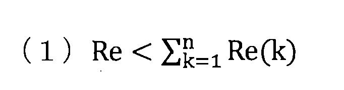
上記式は、市販の測定装置を用いて得られる多層積層フィルム全体の位相差Reが、各層の位相差を個別に測定・算出し、それぞれの位相差を加算して得られた値よりも小さくなることを意味する。ここで、各層の位相差を測定する場合には、各層を剥離して単膜になったフィルムを市販の測定装置で測定しても良いし、特開2014-149346号公報にあるように表層を、プラスチック用研磨布で研磨し、各層を単層にした後に測定しても良い。位相差の減算効果が大きいほど、強い配向が交差されていることを示す。この観点から、減算効果は、50nm以上が好ましい。より好ましくは、100nm以上である。
また、一般的に同じ製膜条件で逐次二軸あるいは一軸延伸によるフィルム製膜をした場合、樹脂の結晶性が高い程、面内位相差は大きくなるため、結晶性樹脂aを用いたときのフィルムの位相差をRe(a)、前記樹脂aよりも結晶性の低い樹脂bを用いたときのフィルムの位相差をRe(b)とすると、
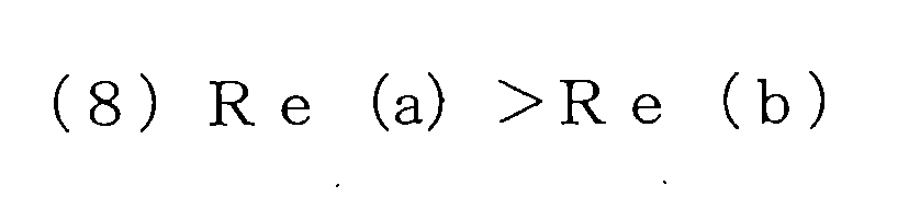
上記(8)式が成り立つ。従って、多層積層フィルムの内層樹脂の位相差が測定困難な場合は、上記式を以下に示す式で簡略化しても良い。

ここで、Re(1)は多層積層フィルムの最表層の位相差、Nx(1)、Ny(1)はそれぞれ最表層の面内方向の最大の屈折率を与える方向の屈折率とそれに垂直な方向の屈折率、d(1)は最表層の厚み、D’は多層積層フィルムにおいて最表層と同じ樹脂が使われている層の総厚みである。この式について、次に説明する。最表層は分光エリプソメーター、分光光度計、プリズムカプラー、アッベ屈折計などを使うことで面内方向の屈折率を求めることができる。次に、走査型電子顕微鏡(SEM)や透過型電子顕微鏡(TEM)を使うことで厚みを測定できるため、最表層の位相差は容易に算出できる。内層の樹脂は、最表層と同じ樹脂の場合、製膜条件が同じであれば、最表層と内層の複屈折は同じであると仮定して、内層の位相差を推定できる。従って、多層積層フィルムの最表層と同じ樹脂に関しては位相差を測定できる。ここで、最表層と同じ樹脂で構成される層の位相差の加算値が、多層積層フィルムの全位相差Reよりも大きければ、既に請求項1の(1)式を満たすことになる。つまり、最表層と異なる樹脂の層の位相差は多層積層フィルムに対して、位相差を減算する効果が働いていることを意味する。
ここで、多層積層フィルムの位相差減算効果について説明する。図1に記載の2層フィルムに関して、A層の面内方向の屈折率をそれぞれNx(a)、Ny(a)、B層の面内方向の屈折率をそれぞれNx(b)、Ny(b)とすると、A層の複屈折は(Nx(a)-Ny(a))、B層の複屈折は(Nx(b)-Ny(b))となるため、図1に記載の2層フィルムの全位相差Reは、
Re =(Nx(a)-Ny(a))×d(a)+(Nx(b)-Ny(b))×d(b)
となる。このとき、B層がA層と同じ樹脂であり、その層をA’と仮定すれば、図2のようになり、Nx(a)=Nx(a’)、 Ny(a)=Ny(a’)となるため、
Re =(Nx(a)-Ny(a))×d(a)
+(Nx(a’)-Ny(a’))×d(a’)
= (Nx(a)-Ny(a))×(d(a)+d(a’))
= (Nx(a)-Ny(a))×d
となり、これはA層単膜の位相差を計算するのと同じ結果になる。ここで、dは2層フィルムの厚みを意味する。従って、多層積層フィルムの全位相差Reは各フィルムの位相差の加算値となることは明白である。そのため、一般的には、各層の屈折率と厚みから求めた位相差の総和と市販の測定装置を用いて測定した積層フィルムの位相差は同じ値になるべきである。
Re =(Nx(a)-Ny(a))×d(a)+(Nx(b)-Ny(b))×d(b)
となる。このとき、B層がA層と同じ樹脂であり、その層をA’と仮定すれば、図2のようになり、Nx(a)=Nx(a’)、 Ny(a)=Ny(a’)となるため、
Re =(Nx(a)-Ny(a))×d(a)
+(Nx(a’)-Ny(a’))×d(a’)
= (Nx(a)-Ny(a))×(d(a)+d(a’))
= (Nx(a)-Ny(a))×d
となり、これはA層単膜の位相差を計算するのと同じ結果になる。ここで、dは2層フィルムの厚みを意味する。従って、多層積層フィルムの全位相差Reは各フィルムの位相差の加算値となることは明白である。そのため、一般的には、各層の屈折率と厚みから求めた位相差の総和と市販の測定装置を用いて測定した積層フィルムの位相差は同じ値になるべきである。
一方で、本発明では結晶性樹脂a及びそれよりも結晶性の低い樹脂bを用いること、及び製膜条件を工夫することにより、各層の位相差を加算した値よりも、多層積層フィルムの全位相差Reを減算させることに成功した。このメカニズムの詳細については後述するが、各層の主配向軸が異なることに由来する。

また、その多層積層フィルムの全体の位相差Re、すなわち、面内方向の位相差は、前記(2)式に示したように400nm以下であることが必要である。このような条件にすることで、サングラス等の偏光子を介して見ても干渉色が観測されがたい多層積層フィルムを得ることが容易となる。クロスニコル下における干渉色は、位相差値と関係しており、Michel-Levyの図表で知られている。偏光子が直交した関係にあるクロスニコル観察したときに、無色となる観点から200nm以下がより好ましい。さらに好ましくは、100nm以下である。その達成方法は、後述する樹脂組成や製膜条件を工夫することである。
本発明の多層積層フィルムの最表層において、面内方向に最大の屈折率を与える方向の屈折率をNx(1)、それに垂直な方向の屈折率をNy(1)、最表層と同じ樹脂から構成される層の総厚みをd(A)、多層積層フィルムの全位相差をReとしたときに、式(5)を満たすことが好ましい。
本発明の多層積層フィルムの最表層において、面内方向に最大の屈折率を与える方向の屈折率をNx(1)、それに垂直な方向の屈折率をNy(1)、最表層と同じ樹脂から構成される層の総厚みをd(A)、多層積層フィルムの全位相差をReとしたときに、式(5)を満たすことが好ましい。

より位相差の減算を発現する観点から、式(5)の左辺は、-50nm以下であることがより好ましい。さらに好ましくは、-100nm以下である。最も好ましくは、-150nm以下である。減算効果を大きくするためには、A層に比べて配向し難いB層も配向させる観点から、積層比であるA層の厚み総和/B層の厚み総和は、1以下が好ましい。より好ましくは、0.7以下である。また、B層に用いられる樹脂bのガラス転移温度は、88℃以上が好ましい。
本発明の多層積層フィルムは、二軸配向可能な結晶性樹脂aと、aよりも結晶性の低い樹脂bを用いてなる必要がある。二軸配向可能な樹脂とは、フィルム長手方向および幅方向に延伸した際に、面内方向の屈折率が厚み方向の屈折率よりも高くなる樹脂である。プリズムカプラー等の光学測定装置を用いて容易に測定可能である。また、結晶性樹脂とは、ガラス転移温度Tgと融点Tmを有する樹脂であり、融解エンタルピー変化ΔHm>0となる樹脂である。好ましい結晶性樹脂のΔHmは、10J/g以上である。より好ましくは20J/gである。また、樹脂bは結晶性樹脂aよりも結晶性が低くなる必要があり、非晶樹脂もこれに含まれる。結晶性樹脂aと樹脂bの結晶性の違いと、その樹脂に適した製膜条件により、逐次延伸した際に多層積層フィルムにおけるA層とB層の主配向軸を変えることができる。結晶性を評価する方法として、DSCで測定されるΔHmの大きさで評価できることが知られている。ΔHmが大きいほど、融解するのにかかるエネルギーが大きいため、結晶性が高いことになる。従って、結晶性樹脂aのΔHmは樹脂bのΔHmよりも高い必要がある。すなわち、ΔHm(a)>ΔHm(b)の関係が成立する。なお、樹脂bは粘着性を有する粘着剤、接着剤及び硬化性樹脂であっても良い。
また、結晶性樹脂aと樹脂bのガラス転移温度は離れていることも好ましい。特に、結晶性樹脂aのガラス転移温度が、樹脂bのガラス転移温度より低いことが好ましい。後述するが、本発明では逐次二軸延伸を採用しており、縦延伸後に横延伸が施される。通常、縦延伸の温度をガラス転移温度よりも十分に高くしていくと、縦延伸での縦方向の配向が進まない。例えば、樹脂bのガラス転移温度が結晶性樹脂aのガラス転移温度よりも高く、樹脂bのガラス転移温度+5℃の条件で縦延伸を行う場合、A層は配向が進まず、一方、A層にくらべてB層の縦方向の配向は強くなる。引き続き、縦延伸の温度より高い温度で横延伸、その後に熱処理を行うことで、A層は結晶性であるため、幅方向に配向結晶化、次いで熱結晶化が進み、一方、B層は縦方向の配向が残存し易いこととなる。結果的にA層とB層の主配向軸をずらすことが可能になる。従って、ガラス転移温度の差は5℃以上離れていることが好ましい。一方、ガラス転移温度の差は大きすぎると、均一延伸できないために厚み均一性が不良となり、縦方向及び幅方向に対して位相差が不均一となる。ガラス転移温度の差は40℃以下が好ましい。
本発明の多層積層フィルムに用いる結晶性樹脂a及びそれよりも結晶性の低い樹脂bとして、具体的にはポリエチレン、ポリプロピレン、ポリ(4-メチルペンテン-1)、ポリアセタールなどのポリオレフィン、シクロオレフィンとしてはノルボルネン類の開環メタセシス重合、付加重合、他のオレフィン類との付加共重合体である脂肪族ポリオレフィン、ポリ乳酸・ポリブチルサクシネートなどの生分解性ポリマー、ナイロン6,11,12,66などのポリアミド、アラミド、ポリメチルメタクリレート、ポリ塩化ビニル、ポリ塩化ビニリデン、ポリビニルアルコール、ポリビニルブチラール、エチレン酢酸ビニルコポリマー、ポリアセタール、ポリグリコール酸、ポリスチレン、スチレン共重合ポリメタクリル酸メチル、ポリカーボネート、ポリプロピレンテレフタレート・ポリエチレンテレフタレート、ポリブチレンテレフタレート、ポリエチレン-2,6-ナフタレートなどのポリエステル、ポリエーテルサルフォン、ポリエーテルケトン、変性ポリフェニレンエーテル、ポリフェニレンサルファイド、ポリエーテルイミド、ポリイミド、ポリアリレート、4フッ化エチレンー6フッ化プロピレン共重合体、ポリフッ化ビニリデン、アクリルニトリル・ブタジエン・スチレン共重合コポリマーなどを用いることができる。この中でも強度、透明性および汎用性の観点からポリメチルメタクリレート、ポリカーボネート、ポリエステルを用いることが好ましい。特に好ましくはポリエステルである。これらはホモポリマーでも共重合ポリマー、さらには熱可塑性樹脂の混合物であってもよい。また、各熱可塑性樹脂中には、各種添加剤、例えば、酸化防止剤、帯電防止剤、結晶核剤、無機粒子、有機粒子、減粘剤、熱安定剤、滑剤、赤外線吸収剤、紫外線吸収剤、屈折率調整のためのドープ剤などが添加されていてもよい。
このポリエステルとしては、芳香族ジカルボン酸または脂肪族ジカルボン酸とジオールを主たる構成成分とする単量体からの重合により得られるポリエステルが好ましい。ここで、芳香族ジカルボン酸として、例えばテレフタル酸、イソフタル酸、フタル酸、1,4-ナフタレンジカルボン酸、1,5-ナフタレンジカルボン酸、2,6-ナフタレンジカルボン酸、4,4’-ジフェニルジカルボン酸、4,4’-ジフェニルスルホンジカルボン酸、4,4‘-ジフェニルジカルボン酸などが挙げられる。脂肪族ジカルボン酸としては例えばアジピン酸、セバシン酸、ダイマー酸、ドデカンジオン酸、シクロヘキサンジカルボン酸とそれらのエステル誘導体などが挙げられる。中でも高い屈折率を発現するテレフタル酸と2,6ナフタレンジカルボン酸を用いることが好ましい。これらの酸成分は1種のみを用いてもよく、2種以上併用してもよく、さらにはヒドロキシ安息香酸のオキシ酸などを一部共重合してもよい。
また、ジオール成分としては、例えば、エチレングリコール、1,2―プロパンジオール、1,3-プロパンジオール、ネオペンチルグリコール、1,3-ブタンジオール、1,4-ブタンジオール、1,5-ペンタンジオール、1,6-ヘキサンジオール、1,2-シクロヘキサンジメタノール、1,3-シクロヘキサンジメタノール、1,4-シクロヘキサンジメタノール、ジエチレングリコール、トリエチレングリコール、ポリアルキレングリコール、2,2―ビス(4-ヒドロキシエトキシフェニル)プロパン、イソソルベート、スピログリコールなどを挙げることができる。中でもエチレングリコールが好ましく用いられる。これらのジオール成分は1種のみで用いてもよく、2種以上併用してもよい。
上記ポリエステルのうち、ポリエチレンテレフタレートおよびその共重合体、ポリエチレンナフタレートおよびその共重合体、ポリブチレンテレフタレートおよびその共重合体、ポリブチレンナフタレートおよびその共重合体、さらにはポリヘキサメチレンテレフタレートおよびその共重合体、ポリシクロヘキシレンジメチレンテレフタレートおよびその共重合体などを用いることが好ましい。
本発明の最も適した樹脂の組み合わせは、二軸配向可能な結晶性樹脂aとしてポリエチレンテレフタレート、ポリエチレンナフタレート、ポリブチレンテレフタレートのいずれか一つを含んでなり、結晶性樹脂aよりも結晶性の低い樹脂bとして、結晶性樹脂aの共重合体が好ましい。前記樹脂bがイソフタル酸、スピログリコール、イソソルビド、フルオレン、ビスフェノールA、シクロヘキンジメタノール成分からなる成分群のいずれかから選ばれた一つの成分以上もつ共重合ポリエステルであることが好ましい。例えばイソフタル酸共重合ポリエチレンテレフタレート、スピログリコール共重合ポリエチレンテレフタレート、イソソルビド共重合ポリエチレンテレフタレート、フルオレン共重合ポリエチレンテレフタレート、ビスフェノールA共重合ポリエチレンテレフタレート、ポリシクロヘキシレンジメチレンテレフタレートのいずれか一つの樹脂含む樹脂を用いるのが好ましい。結晶性樹脂aとの積層性、また位相差の減算効果を発現させる観点から、共重合成分は、5モル%以上50モル%以下が好ましい。5モル%未満であると加算効果が発現しやすく、一方、50モル%以上では減算に関与しなくなる可能性がある。多層積層フィルムの全位相差Reを400m以下とする観点から、より好ましくは、10モル%以上40モル%以下である。
本発明の結晶性樹脂aのガラス転移温度は、樹脂bのガラス転移温度より低い方向が好ましい。逐次二軸延伸フィルムの製膜工程において、縦方向の延伸温度を樹脂bのガラス転移転以上に設定することで、樹脂bからなるB層は縦方向に配向するが、樹脂aからなるA層は縦方向に配向しない。次いで、縦延伸温度より高い温度で横延伸する際は、樹脂aからなるA層は横方向に配向しやすく、一方、樹脂bからなるB層は縦配向が残ったまま、熱処理工程へ導かれる。そこで、A層は横方向に配向結晶化が進む。また、ボーイング現象が加わり、A層とB層の主配向軸が異なる交差した配向状態が実現し、位相差の減算効果が起こりやすいためである。樹脂bのガラス転移温度は、樹脂aより10℃以上高いことが好ましく、より好ましくは20℃以上である。例えば、樹脂aがポリエチレンテレフタレートである場合、そのガラス転移温度は、78℃近傍であるため、樹脂bのガラス転移温度は、88℃以上が好ましい。より好ましくは90°以上、さらに、好ましくは95℃以上である。
本発明の結晶性樹脂aのガラス転移温度は、樹脂bのガラス転移温度より低い方向が好ましい。逐次二軸延伸フィルムの製膜工程において、縦方向の延伸温度を樹脂bのガラス転移転以上に設定することで、樹脂bからなるB層は縦方向に配向するが、樹脂aからなるA層は縦方向に配向しない。次いで、縦延伸温度より高い温度で横延伸する際は、樹脂aからなるA層は横方向に配向しやすく、一方、樹脂bからなるB層は縦配向が残ったまま、熱処理工程へ導かれる。そこで、A層は横方向に配向結晶化が進む。また、ボーイング現象が加わり、A層とB層の主配向軸が異なる交差した配向状態が実現し、位相差の減算効果が起こりやすいためである。樹脂bのガラス転移温度は、樹脂aより10℃以上高いことが好ましく、より好ましくは20℃以上である。例えば、樹脂aがポリエチレンテレフタレートである場合、そのガラス転移温度は、78℃近傍であるため、樹脂bのガラス転移温度は、88℃以上が好ましい。より好ましくは90°以上、さらに、好ましくは95℃以上である。
次に本発明のフィルムの好ましい製造方法について説明する。
まず、結晶性樹脂a、樹脂bをペレットなどの形態で用意する。ペレットは、必要に応じて、熱風中あるいは真空下で乾燥された後、別々の押出機に供給される。押出機内において、融点以上に加熱溶融された樹脂は、ギヤポンプ等で樹脂の押出量を均一化され、フィルター等を介して異物や変性した樹脂などを取り除かれる。
これらの2台以上の押出機を用いて異なる流路から送り出された結晶性樹脂aおよび樹脂bは、次に多層積層装置に送り込まれる。多層積層装置としては、マルチマニホールドダイやフィードブロックやスタティックミキサー等を用いることができる。またこれらを任意に組み合わせても良い。中でも、本発明の効果を効率よく得るためには、各層毎の厚みを個別に制御できるマルチマニホールドダイもしくはフィードブロックが好ましい。フィードブロックの構造は、多数の微細スリットを有する櫛型のスリット板に部材を少なくとも1個有しており、2つの押出し機から供給された結晶性樹脂aと樹脂bが各マニホールドを経由して、スリット板に導入される。ここでは、導入板を介して、結晶性樹脂aと樹脂bが交互に流入するため、最終的にはA/B/A/B/・・・といった多層構造を形成することができる。また、スリット板を重ね合わせることで、層数を増やすことも可能である。なお、スリット形状(長さ、間隙)を調整することで、層の厚みを制御することができる。また、3台目の別の押出機を用いて、この多層積層フィルムの最表層に樹脂cからなるC層をつけることも可能である。これらの積層装置および多層積層フィルムの製造方法については、特開2007-307893号公報および特開2007-79349公報に詳しく説明されており、これらを採用することが好ましい。積層数は、位相差制御や光の波長レベルの層による光干渉反射などの機能を付加的に生み出す観点から、9層以上が好ましい。より好ましくは、50層以上であり、さらに好ましくは200層以上である。積層数が大きすぎると、フローマーク等の積層乱れが発生しやすくなる観点から600層以下が好ましい。また、平均層厚みは、0.04~10μmが好ましい。0.04μ未満であると、各層の光学的な特性や材料的な特性が失われるため、好ましくない。一方、10μmを超えると、フィルムの厚みが厚くなりすぎるため好ましくない。紫外線の反射を付与し、透明性を維持する観点から、0.04~0.06μm、または、0.11~5μmが好ましい。
これらの2台以上の押出機を用いて異なる流路から送り出された結晶性樹脂aおよび樹脂bは、次に多層積層装置に送り込まれる。多層積層装置としては、マルチマニホールドダイやフィードブロックやスタティックミキサー等を用いることができる。またこれらを任意に組み合わせても良い。中でも、本発明の効果を効率よく得るためには、各層毎の厚みを個別に制御できるマルチマニホールドダイもしくはフィードブロックが好ましい。フィードブロックの構造は、多数の微細スリットを有する櫛型のスリット板に部材を少なくとも1個有しており、2つの押出し機から供給された結晶性樹脂aと樹脂bが各マニホールドを経由して、スリット板に導入される。ここでは、導入板を介して、結晶性樹脂aと樹脂bが交互に流入するため、最終的にはA/B/A/B/・・・といった多層構造を形成することができる。また、スリット板を重ね合わせることで、層数を増やすことも可能である。なお、スリット形状(長さ、間隙)を調整することで、層の厚みを制御することができる。また、3台目の別の押出機を用いて、この多層積層フィルムの最表層に樹脂cからなるC層をつけることも可能である。これらの積層装置および多層積層フィルムの製造方法については、特開2007-307893号公報および特開2007-79349公報に詳しく説明されており、これらを採用することが好ましい。積層数は、位相差制御や光の波長レベルの層による光干渉反射などの機能を付加的に生み出す観点から、9層以上が好ましい。より好ましくは、50層以上であり、さらに好ましくは200層以上である。積層数が大きすぎると、フローマーク等の積層乱れが発生しやすくなる観点から600層以下が好ましい。また、平均層厚みは、0.04~10μmが好ましい。0.04μ未満であると、各層の光学的な特性や材料的な特性が失われるため、好ましくない。一方、10μmを超えると、フィルムの厚みが厚くなりすぎるため好ましくない。紫外線の反射を付与し、透明性を維持する観点から、0.04~0.06μm、または、0.11~5μmが好ましい。
このようにして多層積層された溶融体を、スリット状のダイからシート状に押出し、静電印加などの方式によりキャスティングドラムに密着、冷却固化して未延伸シートとした後、二方向に延伸、熱処理することが好ましい。また、フィルムに走行性(易滑性)や耐候性、耐熱性などの機能を持たせるため、フィルム原料に粒子を添加してもよいが、フィルムの高透明性を損なわないように添加量や材質に十分な注意が必要である。添加量については好ましくはきわめて少量、さらに好ましくは無添加である。フィルムの走行性(易滑性)に関しては、前述のように易接着層の添加粒子で補助するのが好ましい。フィルム原料に添加する粒子の材質としては、添加剤、例えば、耐熱安定剤、耐酸化安定剤、耐候安定剤、紫外線吸収剤、易滑剤としてポリイミド、ポリアミドイミド、ポリメチルメタクリレート、ホルムアルデヒド樹脂、フェノール樹脂、架橋ポリスチレンなどの有機微粒子、同じく、湿式および乾式シリカ、コロイダルシリカ、ケイ酸アルミニウム、酸化チタン、炭酸カルシウム、リン酸カルシウム、硫酸バリウム、アルミナ、マイカ、カオリン、クレーなどの無機微粒子などが使用できる。
このようにして得られた積層フィルムは、同時二軸、逐次二軸、斜め延伸及び熱処理を行うことが好ましい。ここで、二軸延伸とは、長手方向(縦方向)および幅方向(横方向)に延伸することをいう。本発明では、A層とB層の主配向軸がずれることが必要であるため、延伸は逐次に二方向に延伸するのが最も好ましい。また、二軸延伸後にさらに長手方向および/または幅方向に再延伸を行ってもよい。
逐次二軸延伸について説明する。ここで、長手方向への延伸とは、フィルムに長手方向の分子配向を与えるための延伸を言い、通常は、ロールの周速差により施され、この延伸は1段階で行ってもよく、また、複数本のロール対を使用して多段階に行っても良い。延伸の倍率としては樹脂の種類により異なるが、通常、2~15倍が好ましく、多層積層フィルムを構成する樹脂のいずれかにPETを用いた場合には、2~7倍が特に好ましく用いられる。また、延伸温度としては多層積層フィルムを構成する樹脂のガラス転移温度~ガラス転移温度+100℃が好ましい。ここで、特に本発明の積層フィルムにおいては、結晶性樹脂aまたは樹脂bのどちらか一方の縦延伸における配向を強めることも好ましい。配向を強めるために好ましい延伸条件は、ガラス転移温度―10℃から+10℃の範囲で延伸することであるため、樹脂bの方のガラス転移温度が高ければ、樹脂bのガラス転移温度±10℃以内で2.8~3.7倍に延伸することが好ましい。さらに好ましくは、樹脂bのガラス転移温度+10℃以内で3.3~3.7倍である。
このようにして得られた一軸延伸されたフィルムに、必要に応じてコロナ処理やフレーム処理、プラズマ処理などの表面処理を施した後、易滑性、易接着性、帯電防止性などの機能をインラインコーティングにより付与してもよい。
また、幅方向の延伸とは、フィルムに幅方向の配向を与えるための延伸をいい、通常は、テンター法を用いる。これは、フィルムの両端をクリップで把持しながら搬送して、幅方向に延伸する。延伸の倍率としては樹脂の種類により異なるが、通常、2~15倍が好ましく、多層積層フィルムを構成する樹脂のいずれかにPETを用いた場合には、2~7倍が特に好ましく用いられる。また、延伸温度としては多層積層フィルムを構成する樹脂のガラス転移温度~ガラス転移温度+120℃が好ましい。
ここで、特に本発明の多層積層フィルムにおいては、フィルム幅方向の位相差の抑制ならびにフィルム幅方向の位相差や配向角の均一性の向上のためにフィルム幅方向への延伸時に段階的に延伸温度を低温から高温へと昇温する方法や、フィルム幅方向への延伸時に高延伸倍率で延伸したのちに低延伸倍率で延伸する方法などを採用することも好ましい。位相差や配向角の幅方向均一性の低下の原因の一つは、幅方向延伸時にフィルム流れ方向に働く延伸応力に伴うことが多い。ここで、上記の方法を採用することにより、フィルム幅方向への延伸時にフィルム流れ方向で生じる応力を抑制でき、相対的にフィルム幅方向の応力を高めることができるため、フィルム幅方向での位相差や配高角の均一化を達成できるものである。本発明において、横延伸温度は100℃以上で3.3~4.6倍に延伸することが好ましい。
全位相差Reは、縦横の延伸比率に依存しているため、縦延伸倍率/横延伸倍率の比は1に近い方が好ましい。全位相差Reを400nm以下とするためには、前記比が0.6以上好ましく、0.7以上がより好ましい。
こうして二軸延伸されたフィルムは、平面性、寸法安定性を付与するために、テンター内で延伸温度以上融点以下の熱処理を行うのが好ましい。熱処理を行うことにより、熱結晶化が進むために、熱寸法安定性が向上する。このようにして熱処理された後、均一に徐冷後、室温まで冷やして巻き取られる。また、必要に応じて、熱処理から徐冷の際に弛緩処理などを併用してもよい。
ここで、特に本発明の多層積層フィルムにおいては、フィルム幅方向の位相差のムラを抑制するためにフィルム幅方向に延伸した後に、一旦、ガラス転移温度以下に冷却した後に熱処理を行うことも好ましい。この場合、ガラス転移温度以下に冷却することでフィルム幅方向への延伸工程におけるフィルム流れ方向の延伸応力を抑制することが可能となり、結果としてフィルム幅方向での位相差の均一性を高められるものである。
また、本発明の多層積層フィルムにおいては、熱処理時の温度を段階的に昇温することも好ましい。より好ましくは、フィルム幅方向への延伸終了時の温度をT1、熱処理開始時の温度をT2、熱処理工程の最高温度をT3とした場合、T2はT1+10℃以上であり、かつT3-10℃以下であることであり、さらに好ましくはT2が(T1+T3)/2±10℃の範囲にあることである。このように、熱処理温度を段階的に昇温することでも、フィルム幅方向への延伸工程におけるフィルム流れ方向の延伸応力を抑制することが可能となり、結果としてフィルム幅方向での位相差の均一性を高められるものである。また、本発明の多層積層フィルムにおいては、熱処理工程においてもフィルム幅方向への延伸工程終了後のフィルム幅に対して1.01倍以上1.2倍以下で延伸することも好ましい。熱処理工程においては、フィルム長手方向への応力はほとんど生じないため、幅方向での位相差や配向角の均一性を向上させることができる。一方、熱処理工程でのフィルム幅方向への延伸倍率が1.2倍より大きくなった場合には、フィルムに厚みムラが生じ、逆に位相差が悪化する場合もある。得られた多層積層フィルムの厚みは、薄膜化の観点から、30μm以下が好ましい。より好ましくは、20μm以下である。さらに、好ましくは、15μm以下である。
本発明の多層積層フィルムの幅方向に対する主配向軸の傾きが10~80°の多層積層フィルムであって、多層積層フィルムに含まれるA層の主配向軸とB層の主配向軸とがなす角度が、60~120°となることが好ましい。主配向軸とは、面内の屈折率において、最も屈折率が高くなる方位を示し、基準線に対する配向角と称することもある。ここでの主配向軸の傾きは、絶対値である。配向角の測定方法は、KOBRA-21ADHでは全位相差Reのみ測定可能である。プリズムカプラーは、最表層の屈折率のみを直接的に求めることができる。一方、FT-IRの偏光ATR法で測定することにより、配向パラメータを用いて、各層の主配向軸を直接的に測定可能である。次に詳しく説明する。配向パラメータとしては、ポリエチレンタレフタレートやイソフタル酸共重合ポリエチレンテレフタレートは、1340cm-1(CH2縦揺れ振動:トランス体)のピーク強度/1410cm-1(芳香環:C=C伸縮振動)のピーク強度の比を面内方位15°刻みで調べることにより、主配向軸を求めることができる。次に、イソソルビド共重合ポリエチレンテレフタレートは、イソソルビド特有のピークである1097cm-1のピーク強度/1410cm-1のピーク強度の比、一方、スピログリコール共重合ポリエチレンテレフタレートでは、1165cm-1のピーク強度/1410cm-1のピーク強度の比を配向パラメータとして、それぞれ面内方位で調べることにより、主配向軸を求めることができる。多層積層フィルムに含まれるA層の主配向軸とB層の主配向軸とがなす角度が、60°未満、あるいは120°を超えると位相差の減算効果が少なくなるため、好ましくは70°~110°である。より好ましくは、80°~100°である。なお、A層とB層の配向パラメータを独立に求める方法は、厚み方向において乾式研磨を行うことで測定できる。
また、本発明の多層積層フィルムは、フィルム幅方向における位相差ムラが50nm/200mm以下であることが好ましい。位相差ムラが50nm/200mmを超えると、ディスプレイ用途での偏光子保護フィルムとして用いられた際に、色ムラが発生する。より好ましくは、30nm/200mm以下である。
本発明の多層積層フィルムは、波長350nmにおける反射率が20%以上であることが好ましい。偏光板用途では、偏光子の光劣化を防ぐために、偏光子保護フィルムはUVカットが求めるためである。また、後述する液晶材料を含んでなるC層について、光によるラジカル重合による硬化反応は、主に波長365nmのI線近傍の光が主に用いられる。多層積層フィルム自体が紫外線を反射すると、光反応に利用する紫外光が塗膜の下面から逃げずに再帰反射し、塗膜に再度、照射される。そのため、C層の液晶材料を光配向させる速度が速まり、所望の異方性を実現する光配向膜を形成し易くできる。より好ましくは、反射率が30%以上である。さらに好ましくは、50%以上である。
本発明である集合多層積層フィルムは、結晶性樹脂aからなるA層と、前記結晶性樹脂aよりも結晶性の低い樹脂bからなるB層が、少なくとも2層以上積層された第1の多層積層フィルムと、第2の多層積層フィルムと、順次、第k番目の多層積層フィルムまでが重ね合わさった集合体である。そのk番目における多層積層フィルムの位相差をRe(k)、全ての多層積層フィルムの数をnとした時に、多層積層フィルムの集合体としての全位相差SReが下記式(3)を満たすことが必要である。kは自然数。
本発明の多層積層フィルムの幅方向に対する主配向軸の傾きが10~80°の多層積層フィルムであって、多層積層フィルムに含まれるA層の主配向軸とB層の主配向軸とがなす角度が、60~120°となることが好ましい。主配向軸とは、面内の屈折率において、最も屈折率が高くなる方位を示し、基準線に対する配向角と称することもある。ここでの主配向軸の傾きは、絶対値である。配向角の測定方法は、KOBRA-21ADHでは全位相差Reのみ測定可能である。プリズムカプラーは、最表層の屈折率のみを直接的に求めることができる。一方、FT-IRの偏光ATR法で測定することにより、配向パラメータを用いて、各層の主配向軸を直接的に測定可能である。次に詳しく説明する。配向パラメータとしては、ポリエチレンタレフタレートやイソフタル酸共重合ポリエチレンテレフタレートは、1340cm-1(CH2縦揺れ振動:トランス体)のピーク強度/1410cm-1(芳香環:C=C伸縮振動)のピーク強度の比を面内方位15°刻みで調べることにより、主配向軸を求めることができる。次に、イソソルビド共重合ポリエチレンテレフタレートは、イソソルビド特有のピークである1097cm-1のピーク強度/1410cm-1のピーク強度の比、一方、スピログリコール共重合ポリエチレンテレフタレートでは、1165cm-1のピーク強度/1410cm-1のピーク強度の比を配向パラメータとして、それぞれ面内方位で調べることにより、主配向軸を求めることができる。多層積層フィルムに含まれるA層の主配向軸とB層の主配向軸とがなす角度が、60°未満、あるいは120°を超えると位相差の減算効果が少なくなるため、好ましくは70°~110°である。より好ましくは、80°~100°である。なお、A層とB層の配向パラメータを独立に求める方法は、厚み方向において乾式研磨を行うことで測定できる。
また、本発明の多層積層フィルムは、フィルム幅方向における位相差ムラが50nm/200mm以下であることが好ましい。位相差ムラが50nm/200mmを超えると、ディスプレイ用途での偏光子保護フィルムとして用いられた際に、色ムラが発生する。より好ましくは、30nm/200mm以下である。
本発明の多層積層フィルムは、波長350nmにおける反射率が20%以上であることが好ましい。偏光板用途では、偏光子の光劣化を防ぐために、偏光子保護フィルムはUVカットが求めるためである。また、後述する液晶材料を含んでなるC層について、光によるラジカル重合による硬化反応は、主に波長365nmのI線近傍の光が主に用いられる。多層積層フィルム自体が紫外線を反射すると、光反応に利用する紫外光が塗膜の下面から逃げずに再帰反射し、塗膜に再度、照射される。そのため、C層の液晶材料を光配向させる速度が速まり、所望の異方性を実現する光配向膜を形成し易くできる。より好ましくは、反射率が30%以上である。さらに好ましくは、50%以上である。
本発明である集合多層積層フィルムは、結晶性樹脂aからなるA層と、前記結晶性樹脂aよりも結晶性の低い樹脂bからなるB層が、少なくとも2層以上積層された第1の多層積層フィルムと、第2の多層積層フィルムと、順次、第k番目の多層積層フィルムまでが重ね合わさった集合体である。そのk番目における多層積層フィルムの位相差をRe(k)、全ての多層積層フィルムの数をnとした時に、多層積層フィルムの集合体としての全位相差SReが下記式(3)を満たすことが必要である。kは自然数。

上記式を満足することにより、複数の多層積層フィルムを重ね合わせたとき、集合多層積層フィルムにおいて、位相差の減算効果が発現していることを意味する。干渉色や虹ムラを抑制させる観点から、SReは400nm以下の位相差であることが好ましい。より好ましくは250nm以下である。多層積層フィルムを重ねる枚数である自然数nは、位相差の減算効果を発現する観点から2以上である。また、好ましくは2の倍数である。各多層積層フィルムの主配向軸が直交するように交互に積層すると位相差を減算させやすいためである。各多層積層フィルムの積層間には粘着剤、接着剤、あるいは空気が介在していてもよい。これらには、紫外線吸収剤、色素、光安定剤などの各種添加剤が含まれていても良い。また、位相差に殆ど関与しない蒸着等で得られる金属や金属酸化物の加工が施されていても良い。重ね合わせる多層積層フィルムは、同一製膜から得られた多層積層フィルムの幅方向のサンプリング位置違いであっても良い。または、樹脂組成も異なる多層積層フィルムでも良い。
次に、ボーイング現象が原因で位相差ムラや配向角ムラが大きい多層積層フィルムにおいて、多層積層フィルムの重ね合わせにより、フィルム幅方向全幅で低位相差化を実現する達成方法を説明する。ここで、ボーイング現象とは、逐次二軸延伸フィルムの製造方法において、テンター前でフィルム幅方向に引いたマジックインキの直線が、テンター出口では、テンタークリップ位置を固定転とした弓なり状の曲線となるフィルム変形挙動のことである。その発生メカニズムは、横延伸でポアソン比基づく収縮応力が走行方向と反対に働き、熱固定領域のフィルムを延伸領域に引き込むためである。
本発明の多層積層フィルムを製膜したときのフィルム幅方向での屈折率楕円体の分布に基づいて位相差の減算効果について、図4を用いて詳しく説明する。図4(a)に多層積層フィルムの幅方向での屈折率楕円体の分布を示す。多層積層フィルムの全幅サンプルから切り出されたフィルム幅方向での屈折率楕円体の分布である。C位置は、フィルム幅方向中央部を示す。逐次二軸延伸によるフィルム製膜では、前記したボーイング現象により、フィルム幅方向端部では複屈折(位相差)が大きく、主配向軸の傾き(配向角)も合わせて大きくなる特徴がある。2Wは、フィルム幅の大きさを示す。MD(Machine Direction)の矢印の向きは、フィルム走行方向を示す。2Wは、製造装置の大きさに依存しており、0.5~2m以上が一般的である。ここでの配向角と位相差は、それぞれ、KOBRAで測定可能であるフィルム厚み方向の各層を考慮した全体の配向角、および位相差である。次に、図4(b)に多層積層フィルムを2枚重ねたときの幅方向での多層積層フィルムの屈折率楕円体の分布を示す。長手方向の異なる位置から切り出した同じ多層積層フィルムについて、走行方向を180°反転して重ね合わせた2枚の全幅の多層積層フィルムの屈折率楕円体の分布である。中央部を除き、2枚の多層積層フィルムの屈折率楕円体が交差していることが分かる。その結果、位相差の減算効果が発現し、フィルム全幅での低位相差化を達成する。
図5(a)は、1枚の多層積層フィルムを用いたときの位相差の減算の模式図を示す。図4(a)に記載の全幅の多層積層フィルムを半分にし、走行方向を180°反転して重ね合わせた例であり、図4(b)と同じく、屈折率楕円体が交差しており、位相差の減算効果が働くことが分かる。一方、図5(b)は、走行方向を同じにして中央部で折り返すと屈折率楕円体は重なり、位相差の加算効果が働くことが分かる。これらは、光学特性の線対称性を上手く利用することで、位相差を制御した例である。
本発明の多層積層フィルムを製膜したときのフィルム幅方向での屈折率楕円体の分布に基づいて位相差の減算効果について、図4を用いて詳しく説明する。図4(a)に多層積層フィルムの幅方向での屈折率楕円体の分布を示す。多層積層フィルムの全幅サンプルから切り出されたフィルム幅方向での屈折率楕円体の分布である。C位置は、フィルム幅方向中央部を示す。逐次二軸延伸によるフィルム製膜では、前記したボーイング現象により、フィルム幅方向端部では複屈折(位相差)が大きく、主配向軸の傾き(配向角)も合わせて大きくなる特徴がある。2Wは、フィルム幅の大きさを示す。MD(Machine Direction)の矢印の向きは、フィルム走行方向を示す。2Wは、製造装置の大きさに依存しており、0.5~2m以上が一般的である。ここでの配向角と位相差は、それぞれ、KOBRAで測定可能であるフィルム厚み方向の各層を考慮した全体の配向角、および位相差である。次に、図4(b)に多層積層フィルムを2枚重ねたときの幅方向での多層積層フィルムの屈折率楕円体の分布を示す。長手方向の異なる位置から切り出した同じ多層積層フィルムについて、走行方向を180°反転して重ね合わせた2枚の全幅の多層積層フィルムの屈折率楕円体の分布である。中央部を除き、2枚の多層積層フィルムの屈折率楕円体が交差していることが分かる。その結果、位相差の減算効果が発現し、フィルム全幅での低位相差化を達成する。
図5(a)は、1枚の多層積層フィルムを用いたときの位相差の減算の模式図を示す。図4(a)に記載の全幅の多層積層フィルムを半分にし、走行方向を180°反転して重ね合わせた例であり、図4(b)と同じく、屈折率楕円体が交差しており、位相差の減算効果が働くことが分かる。一方、図5(b)は、走行方向を同じにして中央部で折り返すと屈折率楕円体は重なり、位相差の加算効果が働くことが分かる。これらは、光学特性の線対称性を上手く利用することで、位相差を制御した例である。
本発明である集合多層積層フィルムにおいて、式(3)を満足するためには、少なくとも主配向軸が直交、または60~120°の関係にある2枚の多層積層フィルムの存在が1組以上は必要である。SReを400nm以下とするためには、前記関係の多層積層フィルムの組が、n/2~(n-6)/2組み程度は必要である(n≧2)。
式(3)の多層積層フィルム自体の位相差SRe(k)は、(1)式の全位相差Reと同義であるが、ここでの位相差は、特に限定しない。なぜなら、位相差は、利用される最終形態が重要なためである。例えば、タッチパネル基材において、GFFのフィルムセンサータイプでは、ITO基材フィルムは、2枚用いられる。第1の多層積層フィルムと第2の多層積層フィルムにそれぞれ、ITO加工を行い、基材フィルムとして利用されたときは、個々の位相差が問題ではなく、本発明である集合多層積層フィルムの位相差が重要であり、干渉色、虹ムラに影響するからである。しかしながら、低位相差である方が、制御し易い観点から、多層積層フィルム自体の位相差SRe(k)も400nm以下であることが好ましい。
本発明である複合多層積層フィルムは、結晶性樹脂aからなるA層と、前記結晶性樹脂aよりも結晶性の低い樹脂bからなるB層が、少なくとも3層以上交互に積層された多層積層フィルムの上に、液晶材料を含んでなるC層が積層された複合多層積層フィルムであって、複合多層積層フィルムの全厚み方向の位相差Rth’と多層積層フィルムの全厚み方向位相差Rthが式(4)を満たすことが必要である。
式(3)の多層積層フィルム自体の位相差SRe(k)は、(1)式の全位相差Reと同義であるが、ここでの位相差は、特に限定しない。なぜなら、位相差は、利用される最終形態が重要なためである。例えば、タッチパネル基材において、GFFのフィルムセンサータイプでは、ITO基材フィルムは、2枚用いられる。第1の多層積層フィルムと第2の多層積層フィルムにそれぞれ、ITO加工を行い、基材フィルムとして利用されたときは、個々の位相差が問題ではなく、本発明である集合多層積層フィルムの位相差が重要であり、干渉色、虹ムラに影響するからである。しかしながら、低位相差である方が、制御し易い観点から、多層積層フィルム自体の位相差SRe(k)も400nm以下であることが好ましい。
本発明である複合多層積層フィルムは、結晶性樹脂aからなるA層と、前記結晶性樹脂aよりも結晶性の低い樹脂bからなるB層が、少なくとも3層以上交互に積層された多層積層フィルムの上に、液晶材料を含んでなるC層が積層された複合多層積層フィルムであって、複合多層積層フィルムの全厚み方向の位相差Rth’と多層積層フィルムの全厚み方向位相差Rthが式(4)を満たすことが必要である。

液晶材料とは、重合性液晶組成物を含み、分子内に重合性官能基を有する液晶化合物(棒状液晶構造)を含有する構造をもつ。液晶化合物は、屈折率異方性を有し、様々な配向形態を付与することにより所望の位相差機能を発現する。液晶化合物として、例えば、ネマチック相、コレステリック相、スメクチック相等の液晶相を示す材料が挙げられる。
液晶化合物は、重合性官能基を有することで、数種の液晶化合物を重合して固定することができる。重合性官能基としては、例えば、紫外線、電子線、熱の作用によって重合することができ、光ラジカル重合タイプや光カチオン重合タイプが挙げられる。ラジカル重合タイプの例としては、ビニル基、アクリレート基(アクリロイル基、メタクリロイル基、アクリロイルオキシ基、メタクリロイルオキシ基を包含する総称)等が挙げられる。
本発明の液晶材料は、感光性液晶高分子を含有することが好ましい。また、液晶高分子中にメソゲン成分を含むことが好ましい。さらに、メソゲン成分を側鎖に含む側鎖型液晶性高分子材料であることが好ましい。主鎖を構成する材料としては、炭化水素、アクリレート、メタクリレート、ビニル、シロキサン、マレインイミド、N-フェニルマレインイミドなどが挙げられる。メソゲン成分は、ベンゼン環、ナフタレン環、フルオレン環などの芳香族環又は、シクロヘキサン環などの脂肪族環と、これを結合する連結基とで構成される。例えば、ビフェニル、ターフェニル、フェニルベンゾエート、アゾベンゼンなどである。このような液晶性高分子材料は、同一の繰り返し単位からなる単一重合体または構造の異なる側鎖を有する単位の共重合体でもよい。また、液晶性を損なわない程度に耐熱性や耐溶媒性を向上させるための架橋剤を添加してもよい。耐熱性を向上させるために添加される架橋剤としては、イソシアネート材料、エポキシ材料などの架橋剤を挙げることができる。
液晶材料を溶解する溶媒としては、ベンゼン、ヘキサン等の炭化水素系溶媒、メチルエチルケトン、メチルイソブチルケトン、シクロヘキサノン等のケトン系溶媒、テトラヒドロフラン、1,2-ジメトキシエタン、プロピレングリコールモノエチルエーテル、メチルtert-ブチルエーテル、1,4-ジオキサン、ジエチレングリコールジメチルエーテル(diglyme)、エチレングリコールジメチルエーテル、1,3-ジオキソラン、2-メチルテトラヒドロフラン等のエーテル系溶媒、クロロホルム、ジクロロメタン等のハロゲン化アルキル系溶媒、酢酸メチル、酢酸エチル、酢酸ブチル、プロピレングリコールモノメチルエーテルアセテート等のエステル系溶媒、N,N-ジメチルホルムアミド等のアミド系溶媒、ジメチルスルホキシド等のスルホキシド系溶媒、シクロヘキサン等のアノン系溶媒、メタノール、エタノール、イソプロピルアルコール等のアルコール系溶媒これらの溶媒は、単独で、または二種以上組み合わせて使用してもよい。
液晶材料を含んでなるC層となる溶液を多層積層フィルム上に塗布する際は、グラビア、フレキソ、ダイスリット、スピンコートの方法で達成できる。
感光性液晶高分子は、例えば、日本特開2007-232934、日本特開2012-177087公報に記載の通り、縮合反応させて形成することができる。次いで、C層を硬化させて屈折率異方性を付与するために、波長250~400nmの紫外線を照射する。照射する光は、円偏光、楕円偏光などでも良いが、感光性液晶高分子中のメソゲン部分を異方的に配向させる観点から直線偏光が好ましい。その際、光反応を高める観点から、多層積層フィルムは、波長400nm以下の紫外線を反射することが好ましい。紫外線を反射することでC層の光硬化効率が高まるためである。波長350nmにおける反射率は、30%以上あることが好ましい。より好ましくは、50%以上である。配向制御の観点から、負のCプレートなら塗膜面に対して、法線方向または斜め法線から傾斜した方向から光を照射する。光源としては、例えば高圧水銀灯やキセノン光源など紫外線を発光するものならいかなる光源を用いてもよい。照射量は、20~300mJ/cm2程度としてもよい。その後、熱処理70~150℃での熱処理を施すことにより、偏光した紫外線光により配向固定されなかった側鎖等が配向固定される。
本発明の液晶材料の厚みは、薄膜化が求められる観点と、異方性を付与し、厚み方向の位相差を発現させる観点から0.1μm以上から10μm以下が好ましい。より好ましくは、0.5μmから5μm以下である。本発明の多層積層フィルムは、二軸配向可能な結晶性樹脂aを用いるため、強い負のCプレートとなりやすい。本発明の多層積層フィルムにおいて、クロスニコル下における視野角による干渉色をなくすためには、厚み方向位相差の減算効果が求められるため、液晶材料を含むC層は正のCプレートであることが好ましい。負のCプレートとは、厚み方向の屈折率Nzより面内方向の屈折率Nx、Nyの方が高い屈折率楕円体のことであり、一方、正のCプレートとは、厚み方向の屈折率Nzの方が、面内方向の屈折率Nx、Nyより高い屈折率楕円体をもつ材料を意味する。正のCプレートを作成する方法は、塗布面の法線方向から45°以上90°未満傾けた方位から直線偏光した紫外線光を照射し、その後、加熱処理することで、液晶材料の厚み方向の屈折率向上を誘発し、達成される。正のCプレートする観点から、60°以上90°未満の入射角からの照射が、より好ましい。入射角とは、塗膜面の法線に対する傾斜角を意味する。
本発明のC層の厚み方向の屈折率Nzと面内方向の屈折率NX、NYの関係が、下記式(6)と式(7)を満足することが好ましい。
液晶化合物は、重合性官能基を有することで、数種の液晶化合物を重合して固定することができる。重合性官能基としては、例えば、紫外線、電子線、熱の作用によって重合することができ、光ラジカル重合タイプや光カチオン重合タイプが挙げられる。ラジカル重合タイプの例としては、ビニル基、アクリレート基(アクリロイル基、メタクリロイル基、アクリロイルオキシ基、メタクリロイルオキシ基を包含する総称)等が挙げられる。
本発明の液晶材料は、感光性液晶高分子を含有することが好ましい。また、液晶高分子中にメソゲン成分を含むことが好ましい。さらに、メソゲン成分を側鎖に含む側鎖型液晶性高分子材料であることが好ましい。主鎖を構成する材料としては、炭化水素、アクリレート、メタクリレート、ビニル、シロキサン、マレインイミド、N-フェニルマレインイミドなどが挙げられる。メソゲン成分は、ベンゼン環、ナフタレン環、フルオレン環などの芳香族環又は、シクロヘキサン環などの脂肪族環と、これを結合する連結基とで構成される。例えば、ビフェニル、ターフェニル、フェニルベンゾエート、アゾベンゼンなどである。このような液晶性高分子材料は、同一の繰り返し単位からなる単一重合体または構造の異なる側鎖を有する単位の共重合体でもよい。また、液晶性を損なわない程度に耐熱性や耐溶媒性を向上させるための架橋剤を添加してもよい。耐熱性を向上させるために添加される架橋剤としては、イソシアネート材料、エポキシ材料などの架橋剤を挙げることができる。
液晶材料を溶解する溶媒としては、ベンゼン、ヘキサン等の炭化水素系溶媒、メチルエチルケトン、メチルイソブチルケトン、シクロヘキサノン等のケトン系溶媒、テトラヒドロフラン、1,2-ジメトキシエタン、プロピレングリコールモノエチルエーテル、メチルtert-ブチルエーテル、1,4-ジオキサン、ジエチレングリコールジメチルエーテル(diglyme)、エチレングリコールジメチルエーテル、1,3-ジオキソラン、2-メチルテトラヒドロフラン等のエーテル系溶媒、クロロホルム、ジクロロメタン等のハロゲン化アルキル系溶媒、酢酸メチル、酢酸エチル、酢酸ブチル、プロピレングリコールモノメチルエーテルアセテート等のエステル系溶媒、N,N-ジメチルホルムアミド等のアミド系溶媒、ジメチルスルホキシド等のスルホキシド系溶媒、シクロヘキサン等のアノン系溶媒、メタノール、エタノール、イソプロピルアルコール等のアルコール系溶媒これらの溶媒は、単独で、または二種以上組み合わせて使用してもよい。
液晶材料を含んでなるC層となる溶液を多層積層フィルム上に塗布する際は、グラビア、フレキソ、ダイスリット、スピンコートの方法で達成できる。
感光性液晶高分子は、例えば、日本特開2007-232934、日本特開2012-177087公報に記載の通り、縮合反応させて形成することができる。次いで、C層を硬化させて屈折率異方性を付与するために、波長250~400nmの紫外線を照射する。照射する光は、円偏光、楕円偏光などでも良いが、感光性液晶高分子中のメソゲン部分を異方的に配向させる観点から直線偏光が好ましい。その際、光反応を高める観点から、多層積層フィルムは、波長400nm以下の紫外線を反射することが好ましい。紫外線を反射することでC層の光硬化効率が高まるためである。波長350nmにおける反射率は、30%以上あることが好ましい。より好ましくは、50%以上である。配向制御の観点から、負のCプレートなら塗膜面に対して、法線方向または斜め法線から傾斜した方向から光を照射する。光源としては、例えば高圧水銀灯やキセノン光源など紫外線を発光するものならいかなる光源を用いてもよい。照射量は、20~300mJ/cm2程度としてもよい。その後、熱処理70~150℃での熱処理を施すことにより、偏光した紫外線光により配向固定されなかった側鎖等が配向固定される。
本発明の液晶材料の厚みは、薄膜化が求められる観点と、異方性を付与し、厚み方向の位相差を発現させる観点から0.1μm以上から10μm以下が好ましい。より好ましくは、0.5μmから5μm以下である。本発明の多層積層フィルムは、二軸配向可能な結晶性樹脂aを用いるため、強い負のCプレートとなりやすい。本発明の多層積層フィルムにおいて、クロスニコル下における視野角による干渉色をなくすためには、厚み方向位相差の減算効果が求められるため、液晶材料を含むC層は正のCプレートであることが好ましい。負のCプレートとは、厚み方向の屈折率Nzより面内方向の屈折率Nx、Nyの方が高い屈折率楕円体のことであり、一方、正のCプレートとは、厚み方向の屈折率Nzの方が、面内方向の屈折率Nx、Nyより高い屈折率楕円体をもつ材料を意味する。正のCプレートを作成する方法は、塗布面の法線方向から45°以上90°未満傾けた方位から直線偏光した紫外線光を照射し、その後、加熱処理することで、液晶材料の厚み方向の屈折率向上を誘発し、達成される。正のCプレートする観点から、60°以上90°未満の入射角からの照射が、より好ましい。入射角とは、塗膜面の法線に対する傾斜角を意味する。
本発明のC層の厚み方向の屈折率Nzと面内方向の屈折率NX、NYの関係が、下記式(6)と式(7)を満足することが好ましい。


二軸配向可能な結晶性樹脂aからなる層は、一般的に面内屈折率は1.5~1.8、厚み方向の屈折率は1.6未満である。そのため、(6)式と(7)式をC層が満足することにより、複合多層積層フィルムの厚み方向位相差Rth’は、多層積層フィルムの全厚み方向位相差Rthより、小さくすることができる。すなわち、厚み方向位相差の減算効果を奏する。また、 NX、NYの面内屈折率は、特に限定されないが、多層積層フィルムとの界面での反射を少なくする観点から、1.54~1.62が好ましい。
さらに、C層の主配向軸φcと多層積層フィルムの主配向軸φabのなす狭角|φc-φab|が、50°~90°の関係にあることが好ましい。C層の主配向軸は、液晶材料を光硬化させるための直線偏光を面内方位に回転させることで制御することが可能である。直線偏光は、ポリビニルアルコールにヨウ素を含浸して延伸された偏光子からなる偏光板や2枚の方解石によるブリュースター角を利用して、偏光を取り出すグランテーラープリズムを用いて作り出すことができる。
本発明である多層積層フィルム、集合多層積層フィルム、複合多層積層フィルムは、光学用フィルムとして用いられることが好ましい。光学用フィルムとしては、フラットパネルディルプレイに用いられることが好ましい。例えば、カバーフィルム、飛散防止フィルム、偏光子保護フィルム、位相差フィルム、タッチパネル用基材フィルム、及び偏光板の離型フィルムなどである。本発明の多層積層フィルムは、通常の二軸延伸PETフィルムと異なり、位相差が低い観点から、偏光子保護フィルム、位相差フィルム、タッチパネル用基材フィルムに用いられることが好ましい。偏光子保護フィルムは、液晶ディスプレイに用いられる2枚の偏光板を構成する材料であり、上偏光板の視認側、下偏光板のバックライト側に用いられる。なお、偏光板は、ヨウ素を含浸したポリビニルアルコールを一軸延伸したフィルムの両側に偏光子保護フィルムと位相差フィルムをそれぞれ、接着剤を介して貼り合わせた構成である。
さらに、C層の主配向軸φcと多層積層フィルムの主配向軸φabのなす狭角|φc-φab|が、50°~90°の関係にあることが好ましい。C層の主配向軸は、液晶材料を光硬化させるための直線偏光を面内方位に回転させることで制御することが可能である。直線偏光は、ポリビニルアルコールにヨウ素を含浸して延伸された偏光子からなる偏光板や2枚の方解石によるブリュースター角を利用して、偏光を取り出すグランテーラープリズムを用いて作り出すことができる。
本発明である多層積層フィルム、集合多層積層フィルム、複合多層積層フィルムは、光学用フィルムとして用いられることが好ましい。光学用フィルムとしては、フラットパネルディルプレイに用いられることが好ましい。例えば、カバーフィルム、飛散防止フィルム、偏光子保護フィルム、位相差フィルム、タッチパネル用基材フィルム、及び偏光板の離型フィルムなどである。本発明の多層積層フィルムは、通常の二軸延伸PETフィルムと異なり、位相差が低い観点から、偏光子保護フィルム、位相差フィルム、タッチパネル用基材フィルムに用いられることが好ましい。偏光子保護フィルムは、液晶ディスプレイに用いられる2枚の偏光板を構成する材料であり、上偏光板の視認側、下偏光板のバックライト側に用いられる。なお、偏光板は、ヨウ素を含浸したポリビニルアルコールを一軸延伸したフィルムの両側に偏光子保護フィルムと位相差フィルムをそれぞれ、接着剤を介して貼り合わせた構成である。
本発明の多層積層フィルムは、タッチパネルに用いられることが好ましい。本発明のタッチパネルは、抵抗膜式、光学式、静電容量式のいずれでもよい。静電容量式には、投影型と表面型に大別できる。マルチタッチが可能な観点から投影型静電容量式が最も好ましい。導電層は、金、銀、白金、パラジウム、ロジウム、インジウム、銅、アルミニウム、ニッケル、クロム、チタン、鉄、コバルト、スズ、などの金属およびこれらの合金や、酸化錫、酸化インジウム、酸化チタン、酸化アンチモン、酸化亜鉛、酸化カドミウム、インジウムティンオキサイド(ITO)などの金属酸化物膜、ヨウ化銅などの複合膜によって形成することができる。これらの透明導電膜は真空蒸着、スパッタリング、反応性RFイオンプレーティング、スプレー熱分解法、化学メッキ法、電気メッキ法、CVD法、コーティング法あるいはこれらの組み合わせ法で薄膜を得ることができる。その他、導電性高分子としては、ポリピロール、ポリアニリン、ポリアセチレン、ポリチオフェン、ポリフェニレン・ビニレン、ポリフェニレンスルフィド、ポリ-p-フェニレン、ポリへテロサイクル・ビニレン、特に好ましくは、(3,4-エチレンジオキシチオフェン)(PEDOT)である。その他、カーボンナノチューブやナノ銀なども高い導電性を示すため好ましい。これらは、有機溶媒に溶かすことにより、コーティング法で基材に塗布することができる。コーティング法は、ハードコート層の方法と同様に種々の方法を採用することができる。汎用性の観点から、ITOが好ましい。
アウトセルタイプのタッチセンサーとしては、大別してガラスセンサーとフィルムセンサーに分けられる。ガラスセンサータイプとしては、GG、GG2、G2、G1Mがある。GGとはカバーガラス/ITO/ガラス/ITO、GG2とはカバーガラス/ガラス/ITO/絶縁層/ITO、G2(OGS)とはカバーガラス/ITO/絶縁層/ITO、G1Mとはカバーガラス/ITOを基本構成としたものである。
飛散防止性とブラックアウトを抑制する観点から、本発明の多層積層フィルムをタッチパネルと液晶パネルの間に用いることが好ましい。この場合は、特に、ガラスセンサータイプで用いられることが好ましい。
飛散防止性とブラックアウトを抑制する観点から、本発明の多層積層フィルムをタッチパネルと液晶パネルの間に用いることが好ましい。この場合は、特に、ガラスセンサータイプで用いられることが好ましい。
一方、フィルムセンサータイプとしては、GFF、GF2、G1F、GF1、PFF、PF1があり、いずれを用いてもよい。また、GFFとはカバーガラス/ITO/フィルム/ITO/フィルム、GF2とはカバーガラス/ITO/フィルム/ITO、またはカバーガラス/ITO/絶縁層/ITO/フィルム、G1Fとはカバーガラス/ITO/ITO/フィルム、GF1とはカバーガラス/ITO/フィルム、PFFとはカバープラスチック/ITO/フィルム/ITO/フィルム、P1Mカバープラスチック/ITOを基本構成としたものである。
以下、本発明の多層積層フィルムについて実施例を用いて説明する。
[物性の測定方法ならびに効果の評価方法]
特性値の評価方法ならびに効果の評価方法は次の通りである。
特性値の評価方法ならびに効果の評価方法は次の通りである。
(1)層厚み、積層数、積層構造
層構成は、ミクロトームを用いて断面を切り出したサンプルについて、透過型電子顕微鏡(TEM)、または走査型電子顕微鏡(SEM)観察により求めた。透過型電子顕微鏡は、H?7100FA型((株)日立製作所製)を用い、加速電圧75kVの条件でフィルムの断面を40000倍に拡大観察し、断面写真を撮影、層構成および各層厚みを測定した。なお、場合によっては、コントラストを高く得るために、公知のRuO4やOsO4などを使用した染色技術を用いた。走査型電子顕微鏡は、JSM-6700F(日本電子(株))を用い、加速電圧3kVの条件でフィルムの断面を1500倍に拡大観察し、断面写真を撮影、層構成および各層厚みを測定した。
層構成は、ミクロトームを用いて断面を切り出したサンプルについて、透過型電子顕微鏡(TEM)、または走査型電子顕微鏡(SEM)観察により求めた。透過型電子顕微鏡は、H?7100FA型((株)日立製作所製)を用い、加速電圧75kVの条件でフィルムの断面を40000倍に拡大観察し、断面写真を撮影、層構成および各層厚みを測定した。なお、場合によっては、コントラストを高く得るために、公知のRuO4やOsO4などを使用した染色技術を用いた。走査型電子顕微鏡は、JSM-6700F(日本電子(株))を用い、加速電圧3kVの条件でフィルムの断面を1500倍に拡大観察し、断面写真を撮影、層構成および各層厚みを測定した。
(2)ガラス転移温度(Tg)・融点(Tm)・融解エンタルピー変化(ΔHm)
示差熱量分析(DSC)を用い、サンプルを25℃から290℃まで5℃/minで昇温し、このとき現れる転移点をJIS?K?7122(1987年)に従って測定・算出した。1stRunのDSCにおいて、2つのピークが現れるため、その2つのピークを分割して、2つの樹脂のΔHmを算出した。
装置:SIIナノテクノロジー(株)(旧セイコー電子工業(株))製
“EXTRA DSC6220”
サンプル質量:5mg。
示差熱量分析(DSC)を用い、サンプルを25℃から290℃まで5℃/minで昇温し、このとき現れる転移点をJIS?K?7122(1987年)に従って測定・算出した。1stRunのDSCにおいて、2つのピークが現れるため、その2つのピークを分割して、2つの樹脂のΔHmを算出した。
装置:SIIナノテクノロジー(株)(旧セイコー電子工業(株))製
“EXTRA DSC6220”
サンプル質量:5mg。
(3)最表層屈折率
Sairon Technology社製 プリズムカプラー(SPA-4000)を用いた。3.5cm×3.5cmで切り出したフィルムサンプルを装置に設置し、633nmのレーザーを照射し、TEモードで測定することにより、最表層の面内屈折率を測定した。TMモードで測定することにより、最表層の厚み方向屈折率を測定した。フィルムのMD方向を装置に対して平行に設置することにより長手方向の屈折率、装置に対して垂直方向に設置することにより幅方向の屈折率をそれぞれ測定した。サンプリングは、幅600mmのフィルムロールの中央部よりサンプリングした。なお、実施例17で作成したC層をガラス基材の上に転写し、面内および面直(厚み方向)の屈折率を同様の方法で測定した。
(4)面内位相差(Re)・厚み方向位相差(Rth)・配向角
王子計測機器(株)製 位相差測定装置(KOBRA-21ADH)を用いた。3.5cm×3.5cmで切り出したフィルムサンプルを装置に設置し、入射角0°における波長590nmのレタデーションを測定した。サンプリングは、幅600mmのフィルムロールの中央部よりサンプリングした。厚み方向の位相差は、入射角50°における位相差とした。
Sairon Technology社製 プリズムカプラー(SPA-4000)を用いた。3.5cm×3.5cmで切り出したフィルムサンプルを装置に設置し、633nmのレーザーを照射し、TEモードで測定することにより、最表層の面内屈折率を測定した。TMモードで測定することにより、最表層の厚み方向屈折率を測定した。フィルムのMD方向を装置に対して平行に設置することにより長手方向の屈折率、装置に対して垂直方向に設置することにより幅方向の屈折率をそれぞれ測定した。サンプリングは、幅600mmのフィルムロールの中央部よりサンプリングした。なお、実施例17で作成したC層をガラス基材の上に転写し、面内および面直(厚み方向)の屈折率を同様の方法で測定した。
(4)面内位相差(Re)・厚み方向位相差(Rth)・配向角
王子計測機器(株)製 位相差測定装置(KOBRA-21ADH)を用いた。3.5cm×3.5cmで切り出したフィルムサンプルを装置に設置し、入射角0°における波長590nmのレタデーションを測定した。サンプリングは、幅600mmのフィルムロールの中央部よりサンプリングした。厚み方向の位相差は、入射角50°における位相差とした。
(5)多層積層フィルムのA層とB層の位相差の測定
剥離可能な多層積層フィルムの場合、全ての層を物理的に剥離することした後、KOBRAにて各層の位相差を測定した。剥離不可能な多層積層フィルムでは、最表層(A層)の屈折率をプリズムカプラーにて測定し、フィルムの断面をTEMで観察することで、表層と同じ樹脂の層の総厚みを測定し、A層のRe(A)を算出した。
剥離可能な多層積層フィルムの場合、全ての層を物理的に剥離することした後、KOBRAにて各層の位相差を測定した。剥離不可能な多層積層フィルムでは、最表層(A層)の屈折率をプリズムカプラーにて測定し、フィルムの断面をTEMで観察することで、表層と同じ樹脂の層の総厚みを測定し、A層のRe(A)を算出した。
(6)虹ムラの評価
TCL社製の46インチの液晶ディスプレイ上に、A4カットのフィルムサンプルを設置した。次いで、真上、斜めから見たときに、虹ムラの有無を評価した。
TCL社製の46インチの液晶ディスプレイ上に、A4カットのフィルムサンプルを設置した。次いで、真上、斜めから見たときに、虹ムラの有無を評価した。
(7)フーリエ変換赤外分光光度計(FT-IR)によるA層の主配向軸とB層の主配向軸となす角度の測定
装置名:Bio-Rad Dglab社製FTS-55A
光源:特殊セラミック、検知器:DTGS、条件:窒素雰囲気、分解能4cm-1/積算回数128回、測定波数領域:4000~6000cm-1、測定方法:ATR法、入射角45°、偏光S波。
サンプルはフィルム幅方向中央部から250mm位置からサンプルを取り出し、フィルム長手方向を0°として、面内方向において15°刻みで偏光測定を一回転行い、そのスペクトルの面内における強度分布を求め、最も値が高い強度比を主配向軸とした。また、乾式研磨を用いて、厚み方向の配向評価を行った。
スピログリコール共重合ポリエチレンテレフタレート層の配向評価スペクトル強度比
:ピーク比 A1165 cm-1/A1410cm-1
イソソルビド共重合ポリエチレンテレフタレート層の配向評価スペクトル強度比
:ピーク比 A1097cm-1/A1410cm-1
ポリエチレンテレフタレート層の配向評価スペクトル強度比
:ピーク比 A1340cm-1/A1410cm-1
(8)波長350nmの相対分光反射率の測定
多層積層フィルムのフィルム幅方向中央部から5cm四方のサンプルを切り出した。次いで、日立ハイテクノロジーズ製 分光光度計(U-4100 Spectrophotomater)を用いて、分光透過率及び入射角度φ=10度における相対反射率を測定した。付属の積分球の内壁は、硫酸バリウムであり、標準板は、酸化アルミニウムである。測定波長は、250nm~800nm、スリットは2nm(可視)とし、ゲインは2と設定し、走査速度を600nm/分で測定した。
装置名:Bio-Rad Dglab社製FTS-55A
光源:特殊セラミック、検知器:DTGS、条件:窒素雰囲気、分解能4cm-1/積算回数128回、測定波数領域:4000~6000cm-1、測定方法:ATR法、入射角45°、偏光S波。
サンプルはフィルム幅方向中央部から250mm位置からサンプルを取り出し、フィルム長手方向を0°として、面内方向において15°刻みで偏光測定を一回転行い、そのスペクトルの面内における強度分布を求め、最も値が高い強度比を主配向軸とした。また、乾式研磨を用いて、厚み方向の配向評価を行った。
スピログリコール共重合ポリエチレンテレフタレート層の配向評価スペクトル強度比
:ピーク比 A1165 cm-1/A1410cm-1
イソソルビド共重合ポリエチレンテレフタレート層の配向評価スペクトル強度比
:ピーク比 A1097cm-1/A1410cm-1
ポリエチレンテレフタレート層の配向評価スペクトル強度比
:ピーク比 A1340cm-1/A1410cm-1
(8)波長350nmの相対分光反射率の測定
多層積層フィルムのフィルム幅方向中央部から5cm四方のサンプルを切り出した。次いで、日立ハイテクノロジーズ製 分光光度計(U-4100 Spectrophotomater)を用いて、分光透過率及び入射角度φ=10度における相対反射率を測定した。付属の積分球の内壁は、硫酸バリウムであり、標準板は、酸化アルミニウムである。測定波長は、250nm~800nm、スリットは2nm(可視)とし、ゲインは2と設定し、走査速度を600nm/分で測定した。
[使用した樹脂]
使用した樹脂を以下にまとめる。
使用した樹脂を以下にまとめる。
樹脂1 ポリエチレンテレフタレート(PET):ガラス転移温度80℃
樹脂2 24mol%イソフタル酸共重合ポリエチレンテレフタレート
(PET-I24):ガラス転移温度74℃
樹脂3 6mol%イソフタル酸共重合ポリシクロヘキシレンジメチレンテレフタレート(PCT-I6):ガラス転移温度90℃
樹脂4 PET-I24と15mol%イソソルベード、及び20mol%シクロヘキサンジメタノール共重合ポリエチレンテレフタレートを等量混合した樹脂:ガラス転移温度95℃
樹脂5 ナイロン6
樹脂6 6mol%エチレン共重合ポリプロピレン
樹脂7 17mol%イソフタル酸共重合ポリエチレンテレフタレート(PET-I17)
:ガラス転移温度76℃
樹脂8 12mol%イソフタル酸共重合ポリエチレンテレフタレート(PET-I12)
:ガラス転移温度78℃
樹脂9 30mol%スピログリコ-ル共重合ポリエチレンテレフタレート:ガラス転移温度100℃
樹脂10:20mol%スピログリコ-ル成分と30mol%シクロヘキサンジカルボン酸を共重合した共重合ポリエチレンテレフタレート:ガラス転移温度80℃
(実施例1)
結晶性樹脂aとして樹脂1、樹脂bとして樹脂2を用いた。結晶性樹脂aおよび樹脂bは、それぞれ、180℃・3時間、およびミキサーで予備結晶化後120℃・5時間の乾燥を行った後、別々の2台の押出機に供給した。
結晶性樹脂aおよび樹脂bは、それぞれ、押出機にて270℃の溶融状態とし、40μmメッシュのフィルターを介した後、吐出比が結晶性樹脂a組成物/樹脂b組成物=0.55になるようにスクリューの回転数を調整し、フィードブロックにてA/B/Aの3層となるように樹脂を合流させ積層体とした。このようにして得られた3層からなる積層体を、スリット状のダイからシート状に押出し成形した後、静電印加にて表面温度25℃に保たれたキャスティングドラム上で急冷固化した。
得られたキャストフィルムを85℃に設定したロール群で加熱した後、延伸区間長100mmの間で、フィルム両面からラジエーションヒーターにより急速加熱しながら、縦延伸温度を85℃に設定し、縦方向に3.3倍延伸し、その後一旦冷却した。次に、この一軸延伸フィルムをテンターに導き、95℃の熱風で予熱後、110℃の温度で横方向に3.6倍延伸した。延伸したフィルムは、そのまま、テンター内で210℃の熱風にて熱処理を行い、続いて同温度にて幅方向に5%の弛緩処理を施し、その後、室温まで徐冷後、巻きとり、厚さ42.9μmの多層積層フィルムを得た。
得られた多層積層フィルムの最表層の位相差をプリズムカプラーとSEMを用いて算出し、多層積層フィルム全体の位相差ReはKOBRAを用いて測定した。その結果を表1に示す。この結果より、最表層と同じ結晶性樹脂aで構成されるA層の全位相差Re(A)は、積層フィルムの位相差よりも大きくなっていることがわかる。従って、B層はA層に対して、位相差を減算していることになる。また、多層積層フィルムの位相差Reは277nmであり、400nmを下回る低位相差フィルムであった。そのため、LCD上で虹ムラを観測したところ、全く見えなかった。
樹脂2 24mol%イソフタル酸共重合ポリエチレンテレフタレート
(PET-I24):ガラス転移温度74℃
樹脂3 6mol%イソフタル酸共重合ポリシクロヘキシレンジメチレンテレフタレート(PCT-I6):ガラス転移温度90℃
樹脂4 PET-I24と15mol%イソソルベード、及び20mol%シクロヘキサンジメタノール共重合ポリエチレンテレフタレートを等量混合した樹脂:ガラス転移温度95℃
樹脂5 ナイロン6
樹脂6 6mol%エチレン共重合ポリプロピレン
樹脂7 17mol%イソフタル酸共重合ポリエチレンテレフタレート(PET-I17)
:ガラス転移温度76℃
樹脂8 12mol%イソフタル酸共重合ポリエチレンテレフタレート(PET-I12)
:ガラス転移温度78℃
樹脂9 30mol%スピログリコ-ル共重合ポリエチレンテレフタレート:ガラス転移温度100℃
樹脂10:20mol%スピログリコ-ル成分と30mol%シクロヘキサンジカルボン酸を共重合した共重合ポリエチレンテレフタレート:ガラス転移温度80℃
(実施例1)
結晶性樹脂aとして樹脂1、樹脂bとして樹脂2を用いた。結晶性樹脂aおよび樹脂bは、それぞれ、180℃・3時間、およびミキサーで予備結晶化後120℃・5時間の乾燥を行った後、別々の2台の押出機に供給した。
結晶性樹脂aおよび樹脂bは、それぞれ、押出機にて270℃の溶融状態とし、40μmメッシュのフィルターを介した後、吐出比が結晶性樹脂a組成物/樹脂b組成物=0.55になるようにスクリューの回転数を調整し、フィードブロックにてA/B/Aの3層となるように樹脂を合流させ積層体とした。このようにして得られた3層からなる積層体を、スリット状のダイからシート状に押出し成形した後、静電印加にて表面温度25℃に保たれたキャスティングドラム上で急冷固化した。
得られたキャストフィルムを85℃に設定したロール群で加熱した後、延伸区間長100mmの間で、フィルム両面からラジエーションヒーターにより急速加熱しながら、縦延伸温度を85℃に設定し、縦方向に3.3倍延伸し、その後一旦冷却した。次に、この一軸延伸フィルムをテンターに導き、95℃の熱風で予熱後、110℃の温度で横方向に3.6倍延伸した。延伸したフィルムは、そのまま、テンター内で210℃の熱風にて熱処理を行い、続いて同温度にて幅方向に5%の弛緩処理を施し、その後、室温まで徐冷後、巻きとり、厚さ42.9μmの多層積層フィルムを得た。
得られた多層積層フィルムの最表層の位相差をプリズムカプラーとSEMを用いて算出し、多層積層フィルム全体の位相差ReはKOBRAを用いて測定した。その結果を表1に示す。この結果より、最表層と同じ結晶性樹脂aで構成されるA層の全位相差Re(A)は、積層フィルムの位相差よりも大きくなっていることがわかる。従って、B層はA層に対して、位相差を減算していることになる。また、多層積層フィルムの位相差Reは277nmであり、400nmを下回る低位相差フィルムであった。そのため、LCD上で虹ムラを観測したところ、全く見えなかった。
(実施例2)
実施例1において、樹脂bとして樹脂3を用い、吐出比(積層比)が結晶性樹脂a組成物/樹脂b組成物=1.0、縦延伸温度を105℃、縦延伸倍率を3.3倍、横延伸温度を140℃、横延伸倍率を4.6倍にした以外は同じ条件で実験した。得られた多層積層フィルムの表層の位相差と多層積層フィルムの位相差を比較したところ、実施例1よりも減算効果が大きく、低位相差であることが分かった。その結果を表1に示す。これは、PCT-IがPET-Iに比較して、MD方向への配向が強く、且つPCT-I自体のガラス転移温度がPETより高く、また、その位相差が大きかったため、より減算効果が働いたと考えられる。
実施例1において、樹脂bとして樹脂3を用い、吐出比(積層比)が結晶性樹脂a組成物/樹脂b組成物=1.0、縦延伸温度を105℃、縦延伸倍率を3.3倍、横延伸温度を140℃、横延伸倍率を4.6倍にした以外は同じ条件で実験した。得られた多層積層フィルムの表層の位相差と多層積層フィルムの位相差を比較したところ、実施例1よりも減算効果が大きく、低位相差であることが分かった。その結果を表1に示す。これは、PCT-IがPET-Iに比較して、MD方向への配向が強く、且つPCT-I自体のガラス転移温度がPETより高く、また、その位相差が大きかったため、より減算効果が働いたと考えられる。
(実施例3)
実施例1と同じ樹脂を、スリット数が9個あるスリット板を用いたフィードブロックにて合流させ積層体とした。スリット間隙は、互いに隣り合う層で同じ厚みになるように設計した。それ以外の製膜条件として、吐出比が結晶性樹脂a組成物/樹脂b組成物=0.25、横延伸温度120℃、横延伸倍率3.9倍、熱処理温度230℃とした以外は実施例1と同じ条件とした。結果を表1に示した。実施例1と比較して、実施例2の方がB層の減算効果が高い結果となった。これは、総厚みに対するB層の厚みが増えたことが実施例1と比べて、より位相差の減算効果が働いたと考えられる。
実施例1と同じ樹脂を、スリット数が9個あるスリット板を用いたフィードブロックにて合流させ積層体とした。スリット間隙は、互いに隣り合う層で同じ厚みになるように設計した。それ以外の製膜条件として、吐出比が結晶性樹脂a組成物/樹脂b組成物=0.25、横延伸温度120℃、横延伸倍率3.9倍、熱処理温度230℃とした以外は実施例1と同じ条件とした。結果を表1に示した。実施例1と比較して、実施例2の方がB層の減算効果が高い結果となった。これは、総厚みに対するB層の厚みが増えたことが実施例1と比べて、より位相差の減算効果が働いたと考えられる。
(実施例4)
実施例3において、樹脂bとして樹脂4を用いて積層体を形成した。その他の製膜条件として、縦延伸温度103℃、縦延伸倍率3.3倍、横延伸温度120℃、横延伸倍率3.3倍、熱処理温度230℃とした。結果を表1、及び表2に示す。樹脂bに上記樹脂を用いても、多層積層フィルムに対して、B層の位相差は減算していた。
実施例3において、樹脂bとして樹脂4を用いて積層体を形成した。その他の製膜条件として、縦延伸温度103℃、縦延伸倍率3.3倍、横延伸温度120℃、横延伸倍率3.3倍、熱処理温度230℃とした。結果を表1、及び表2に示す。樹脂bに上記樹脂を用いても、多層積層フィルムに対して、B層の位相差は減算していた。
(実施例5)
実施例4と同じ樹脂を用いて、縦延伸倍率を3.5倍、横延伸倍率を3.3倍にした以外は実施例4と同じ条件で行った。結果を表2に示す。MD方向の延伸倍率を増加させたため、全体の位相差が増加したものの、減算効果ほとんど変わらなかった。
実施例4と同じ樹脂を用いて、縦延伸倍率を3.5倍、横延伸倍率を3.3倍にした以外は実施例4と同じ条件で行った。結果を表2に示す。MD方向の延伸倍率を増加させたため、全体の位相差が増加したものの、減算効果ほとんど変わらなかった。
(実施例6)
実施例4と同じ樹脂を用いて、スリット数491個のスリット板を1枚用いた構成である層フィードブロックにて合流させて、厚み方向に交互に491層積層された積層体とした。但し、用いたスリット板において、両端部に位置した厚膜層を形成するスリット巾が、他の薄膜層を形成するスリット巾の2 倍以上である設計とし、さらに、薄膜層を形成する最小の層厚みと最大の層厚みの比である傾斜度合いを0 . 3 設計とした。ここでは、スリット幅(間隙)は、全て一定とし、長さのみ変化させた。
得られた積層体を縦延伸温度98℃、縦延伸倍率3.3倍、横延伸温度を140℃、横延伸倍率を4.6倍にした以外は実施例5と同じ条件で製膜した。結果を表2に示した。その結果、実施例4と比較して減算効果が大きくなった。
実施例4と同じ樹脂を用いて、スリット数491個のスリット板を1枚用いた構成である層フィードブロックにて合流させて、厚み方向に交互に491層積層された積層体とした。但し、用いたスリット板において、両端部に位置した厚膜層を形成するスリット巾が、他の薄膜層を形成するスリット巾の2 倍以上である設計とし、さらに、薄膜層を形成する最小の層厚みと最大の層厚みの比である傾斜度合いを0 . 3 設計とした。ここでは、スリット幅(間隙)は、全て一定とし、長さのみ変化させた。
得られた積層体を縦延伸温度98℃、縦延伸倍率3.3倍、横延伸温度を140℃、横延伸倍率を4.6倍にした以外は実施例5と同じ条件で製膜した。結果を表2に示した。その結果、実施例4と比較して減算効果が大きくなった。
(実施例7)
実施例6において、縦延伸温度を101℃に上げた以外は全て同じ条件で行った。結果を表2に示す。実施例に比較して、縦配向が弱まり、横倍率がそのままだったため、全体の位相差は上がってしまったが、B層の配向が変わらないため、減算効果は大きかった。
実施例6において、縦延伸温度を101℃に上げた以外は全て同じ条件で行った。結果を表2に示す。実施例に比較して、縦配向が弱まり、横倍率がそのままだったため、全体の位相差は上がってしまったが、B層の配向が変わらないため、減算効果は大きかった。
(実施例8)
実施例7において、横延伸倍率を下げた以外は全て同じ条件で行った。結果を表2に示す。実施例7に比較して、横倍率が下がったため、全体の位相差が低下したが、減算効果は実施例7とほとんど変わらなかった。
実施例7において、横延伸倍率を下げた以外は全て同じ条件で行った。結果を表2に示す。実施例7に比較して、横倍率が下がったため、全体の位相差が低下したが、減算効果は実施例7とほとんど変わらなかった。
(実施例9)
実施例8において、MD方向への収縮率を減少させるため、熱処理中に追延伸を行い、最終倍率を実施例7と同じ条件まで延伸を行った。結果を表2に示す。実施例8に比較して、全体の位相差も低下し、減算効果も最も大きいものとなった。
実施例8において、MD方向への収縮率を減少させるため、熱処理中に追延伸を行い、最終倍率を実施例7と同じ条件まで延伸を行った。結果を表2に示す。実施例8に比較して、全体の位相差も低下し、減算効果も最も大きいものとなった。
(比較例1)
実施例1において、結晶性樹脂aとして樹脂5、樹脂bとして樹脂1用い、縦延伸温度を80℃、縦延伸倍率を3.3倍、横延伸温度を105℃、横延伸倍率を3.9倍、熱処理温度を190℃にした以外は同様に行った。結果を表1に示す。表層のナイロンの位相差は、積層フィルムの全位相差よりも低く、内層のPET層はナイロンの位相差に対して加算していることが分かった。
実施例1において、結晶性樹脂aとして樹脂5、樹脂bとして樹脂1用い、縦延伸温度を80℃、縦延伸倍率を3.3倍、横延伸温度を105℃、横延伸倍率を3.9倍、熱処理温度を190℃にした以外は同様に行った。結果を表1に示す。表層のナイロンの位相差は、積層フィルムの全位相差よりも低く、内層のPET層はナイロンの位相差に対して加算していることが分かった。
(比較例2)
実施例1において、結晶性樹脂aとして樹脂6、樹脂bとして樹脂4を用い、縦延伸倍率を3.3倍、横延伸倍率を4.1倍、熱処理温度を90℃に変更した以外は同様の方法を用いた。このフィルムも表層の位相差に対して、内層の位相差は加算していることが分かった。
実施例1において、結晶性樹脂aとして樹脂6、樹脂bとして樹脂4を用い、縦延伸倍率を3.3倍、横延伸倍率を4.1倍、熱処理温度を90℃に変更した以外は同様の方法を用いた。このフィルムも表層の位相差に対して、内層の位相差は加算していることが分かった。
(比較例3)
実施例1において、樹脂bを樹脂7にした以外は全て同じ条件で実験を行った。結果を表1に示す。
実施例1において、樹脂bを樹脂7にした以外は全て同じ条件で実験を行った。結果を表1に示す。
(比較例4)
実施例1において、樹脂bを樹脂8にした以外は全て同じ条件で実験を行った。結果を表1に示す。
比較例3、4よりイソフタル酸共重合成分が少なくなると、積層フィルムの位相差とA層の位相差の差が大きくなり、樹脂bが減算効果を働いていないことが分かった。
実施例1において、樹脂bを樹脂8にした以外は全て同じ条件で実験を行った。結果を表1に示す。
比較例3、4よりイソフタル酸共重合成分が少なくなると、積層フィルムの位相差とA層の位相差の差が大きくなり、樹脂bが減算効果を働いていないことが分かった。
(比較例5)
実施例4において、縦延伸倍率を3.3倍、横延伸倍率を3.5倍に変えた以外は同じ条件で行った。その結果を表2に示す。全体的な位相差は低下したものの、縦倍率を増加させたため、位相差の減算は無かった。
実施例4において、縦延伸倍率を3.3倍、横延伸倍率を3.5倍に変えた以外は同じ条件で行った。その結果を表2に示す。全体的な位相差は低下したものの、縦倍率を増加させたため、位相差の減算は無かった。
(比較例6)
実施例1において、全ての樹脂を樹脂1に変更し、PET単膜を作製した。延伸条件を最適化し、厚み=40μm、位相差=1881nm、配向角=0°の単膜を作製した。この単膜を重ね合わせて位相差を測定することで、位相差低減メカニズムを調べた。その結果を表3に示す。PET単膜を長手方向に対して、ずれなく重ね合わせた場合、そのフィルムの全位相差は2枚のフィルムの加算値と同等の値になった。一方、2枚のフィルムを長手方向に対して、角度をずらして積層させた場合、45°以上角度がずれると0°時の位相差よりも減算することが分かった。さらにそのずれが大きくなるに従って、フィルム全体の位相差が大きく減算することが分かった。以上の結果より、重なり合う2枚のフィルムの主配向軸が異なることにより位相差が減算することが証明された。
実施例1において、全ての樹脂を樹脂1に変更し、PET単膜を作製した。延伸条件を最適化し、厚み=40μm、位相差=1881nm、配向角=0°の単膜を作製した。この単膜を重ね合わせて位相差を測定することで、位相差低減メカニズムを調べた。その結果を表3に示す。PET単膜を長手方向に対して、ずれなく重ね合わせた場合、そのフィルムの全位相差は2枚のフィルムの加算値と同等の値になった。一方、2枚のフィルムを長手方向に対して、角度をずらして積層させた場合、45°以上角度がずれると0°時の位相差よりも減算することが分かった。さらにそのずれが大きくなるに従って、フィルム全体の位相差が大きく減算することが分かった。以上の結果より、重なり合う2枚のフィルムの主配向軸が異なることにより位相差が減算することが証明された。
この現象について理論的に考察する(図3)。ポリエチレンテレフタレートは屈折率楕円体であり、角度θだけ回転させたときの楕円方程式は、
AX2 +BXY+ CY2 = 1
A = (cos2θ/Nx12+sin2θ/Ny12)
B = 2cosθsinθ(-1/Nx12+1/Ny12)
C = (cos2θ/Ny12+sin2θ/Nx12)
となるため、A層の2層目のX、Y方向の屈折率はそれぞれ、
Nx2= Nx1Ny1/√(Ny12cos2θ+Nx12sin2θ)
Ny2= Nx1Ny1/√(Nx12cos2θ+Ny12sin2θ)
となる。Nx2とNy2の大小を比較すると、θ≧45°でNx2≦Ny2となるため、1層目のA層から見ると、2層目の複屈折はθ≧45°以上で負となる。ここで、第一層目から見ると、全位相差Reは、
Re = (Nx1-Ny1)×Da+(Nx2-Ny2)×Da’
であり、上記式において、第2項が負となるため、フィルム全体の位相差は減算される結果になると考えられる。つまり、重なり合う2枚のフィルムの主配向軸がずれることにより、位相差が減算されると考えられる。この考え方は、2層以上の異なるフィルムにおいても考えられる結果であり、隣り合うフィルムの主配向軸が異なることにより、A層に対する進相軸と遅相軸の逆転が起きる。その結果、各層の位相差は減算する方向に働き、結果として全位相差は減算したと考えられる。
AX2 +BXY+ CY2 = 1
A = (cos2θ/Nx12+sin2θ/Ny12)
B = 2cosθsinθ(-1/Nx12+1/Ny12)
C = (cos2θ/Ny12+sin2θ/Nx12)
となるため、A層の2層目のX、Y方向の屈折率はそれぞれ、
Nx2= Nx1Ny1/√(Ny12cos2θ+Nx12sin2θ)
Ny2= Nx1Ny1/√(Nx12cos2θ+Ny12sin2θ)
となる。Nx2とNy2の大小を比較すると、θ≧45°でNx2≦Ny2となるため、1層目のA層から見ると、2層目の複屈折はθ≧45°以上で負となる。ここで、第一層目から見ると、全位相差Reは、
Re = (Nx1-Ny1)×Da+(Nx2-Ny2)×Da’
であり、上記式において、第2項が負となるため、フィルム全体の位相差は減算される結果になると考えられる。つまり、重なり合う2枚のフィルムの主配向軸がずれることにより、位相差が減算されると考えられる。この考え方は、2層以上の異なるフィルムにおいても考えられる結果であり、隣り合うフィルムの主配向軸が異なることにより、A層に対する進相軸と遅相軸の逆転が起きる。その結果、各層の位相差は減算する方向に働き、結果として全位相差は減算したと考えられる。
今回いくつかの実施例、比較例に用いた多層積層フィルムは、物理的な各層界面での剥離により、各層の配向角を調べることができた。フィルムの全位相差、及び各層の位相差・配向角の結果を表4に示す。実施例4ではA層とB層で配向角が80°程度異なっており、内層と外層で大きく異なっていることが分かった。一方で、比較例1、及び比較例2では、配向角が内層と外層で同等の値であった。以上の結果より、今回製膜したフィルムは、内層と外層の配向角が異なったことで、フィルムの全位相差が減算されたと考えられる。
(実施例10)
滑剤としての平均粒径2.5μmの凝集シリカを0.04重量%含んだ樹脂1を180℃、3時間の真空乾燥後、単軸押出機に投入し、280℃の押出温度で溶融させて、混練した。30μmカットの濾過精度のスクリーンフィルタを介した後、Tダイに供給し、シート状に成形した後、ワイヤーで7kVの静電印可電圧をかけながら、表面温度が25℃に保たれたキャスティングドラム上で急冷固化し、未延伸フィルムを得た。この未延伸フィルムを、縦延伸機にて85℃でフィルム長手方向に3.5倍のロール間延伸を行い、次いで、両端部をクリップで把持するテンターに導き85℃、フィルム幅方向に3.3倍横延伸した後、次いで215℃の熱処理を施し、150℃で約3%のフィルム幅方向に弛緩処理を実施して厚み32μmのポリエステルフィルムを得た。得られたポリエステテルフィルムのフィルム幅方向の位相差と配向角は、表5の通りの結果となった。フィルム幅方向で主配向軸が40~60°を示す均一な配向角分布を示していた。
得られたポリエステルフィルムは幅600mmであり、長手方向1000mm毎に断裁し、600mm×1000mm各の2枚のシートを作製し、1枚の巻き取り方向を反転させ、中央部と中央部、端部と端部を重ねて、1枚目と2枚目の主配向軸同士の挟まれた角度が、90°±15°とし、減算効果が働くように綜研化学社製光学粘着剤SK-1478を用いてドライラミネートした。光学粘着剤の厚みは25μmであり、得られた多層積層フィルムは3層であり、厚みは89μmであった。
得られた3層フィルムの位相差は、フィルム幅方向で均一であり、また、全て50nm以下であり、減算効果が確認された。タッチパネルの導電性基材や反射防止(AR)基材してのディスプレイ用途で用いられる通常ポリエチレンテレフタレートの課題であった虹ムラや干渉色が改善した多層積層フィルムを得ることができた。また、タッチパネル基材では、ITO導電性を2枚のフィルムそれぞれに設けたGFFセンサータイプ(GFF:カバーガラス/ITO/フィルム/ITO/フィルム構成のタッチパネル)に好適な低位相差フィルムを得ることができた。
滑剤としての平均粒径2.5μmの凝集シリカを0.04重量%含んだ樹脂1を180℃、3時間の真空乾燥後、単軸押出機に投入し、280℃の押出温度で溶融させて、混練した。30μmカットの濾過精度のスクリーンフィルタを介した後、Tダイに供給し、シート状に成形した後、ワイヤーで7kVの静電印可電圧をかけながら、表面温度が25℃に保たれたキャスティングドラム上で急冷固化し、未延伸フィルムを得た。この未延伸フィルムを、縦延伸機にて85℃でフィルム長手方向に3.5倍のロール間延伸を行い、次いで、両端部をクリップで把持するテンターに導き85℃、フィルム幅方向に3.3倍横延伸した後、次いで215℃の熱処理を施し、150℃で約3%のフィルム幅方向に弛緩処理を実施して厚み32μmのポリエステルフィルムを得た。得られたポリエステテルフィルムのフィルム幅方向の位相差と配向角は、表5の通りの結果となった。フィルム幅方向で主配向軸が40~60°を示す均一な配向角分布を示していた。
得られたポリエステルフィルムは幅600mmであり、長手方向1000mm毎に断裁し、600mm×1000mm各の2枚のシートを作製し、1枚の巻き取り方向を反転させ、中央部と中央部、端部と端部を重ねて、1枚目と2枚目の主配向軸同士の挟まれた角度が、90°±15°とし、減算効果が働くように綜研化学社製光学粘着剤SK-1478を用いてドライラミネートした。光学粘着剤の厚みは25μmであり、得られた多層積層フィルムは3層であり、厚みは89μmであった。
得られた3層フィルムの位相差は、フィルム幅方向で均一であり、また、全て50nm以下であり、減算効果が確認された。タッチパネルの導電性基材や反射防止(AR)基材してのディスプレイ用途で用いられる通常ポリエチレンテレフタレートの課題であった虹ムラや干渉色が改善した多層積層フィルムを得ることができた。また、タッチパネル基材では、ITO導電性を2枚のフィルムそれぞれに設けたGFFセンサータイプ(GFF:カバーガラス/ITO/フィルム/ITO/フィルム構成のタッチパネル)に好適な低位相差フィルムを得ることができた。
(実施例11)
樹脂aとして、樹脂1を180℃、3時間の真空乾燥後、一方、樹脂bとして樹脂4を80℃の窒素下の乾燥後、それぞれ閉鎖系の搬送ラインにて、単軸押出機と二軸押出機にそれぞれ投入し、それぞれ280℃と280℃の押出温度で溶融させて、混練した。次いで、二軸押出機の2つのベント孔で、その真空圧を0.1kPa以下で真空ベントにより、オリゴマーや不純物などの異物を除去した後、ギアポンプにて吐出比(積層比)が熱可塑性樹脂A/熱可塑性樹脂B=0.7/1になるように計量しながら、特許4552936号記載の積層装置と同じ原理で255層積層装置にて厚み方向に交互に255層積層された積層体とした。また、上に凸の層厚み分布となるように、スリット長さ、間隙を調整し、積層装置とした。A層、B層それぞれについて、層番号に対してその厚みが凸型の層厚み分布を有する傾斜構造とした。A層とB層が交互に、255層積層されており、積層フィルムの両表面近傍が、最も層厚みが薄くなるようにした。次いで、該積層体をTダイに供給し、シート状に成形した後、ワイヤーで8kVの静電印可電圧をかけながら、表面温度が25℃に保たれたキャスティングドラム上で急冷固化し、未延伸フィルムを得た。この未延伸フィルムを、縦延伸機で115℃、フイルム長手方向に3.2倍の延伸を行い、次いで両端部をクリップで把持するテンターに導き110~140℃、フイルム幅方向に4.5倍横延伸した後、次いで180℃、225℃と段階的に熱処理を施し、150℃で約3%のフイルム幅方向に弛緩処理を実施し、厚み13μmの多層積層フィルムを得た。得られた多層積層フィルムの各層の層厚みは、35nmから55nm範囲に全て存在していた。得られた多層積層フィルムの層厚み分布は、平均層厚み分布では、平均層厚み60nmが漸近線となるような凸型の層厚み分布となっていた。得られた多層積層フィルムの分光光度計による波長350nmでの相対反射率は61%であった。フィルム幅方向中央部から、250mm位置において、A層とB層の配向分布をFT-IRで調べた結果を図6に示す。A層の主配向軸は、120°(300°)を示しているのに対して、B層の主配向軸は30°(210°)となり、A層とB層は直交していることを確認した。また、全位相差Reは191nm、一方、プリズムカプラーによる最表層の屈折率差(Nx(1)-Ny(1))とA層の全ての厚みd(A)から求められる位相差は400nmであり、209nmの面内方向の位相差の減算を確認することができた。また、入射角50°での厚み方向位相差Rthは、450nmであり、42インチの液晶ディスプレイの上に配置して、背景色を白としても虹ムラのないフィルムであった。位相差ムラは、フィルム幅方向中央部における200mmでの位相差変化は、20nmであった。
樹脂aとして、樹脂1を180℃、3時間の真空乾燥後、一方、樹脂bとして樹脂4を80℃の窒素下の乾燥後、それぞれ閉鎖系の搬送ラインにて、単軸押出機と二軸押出機にそれぞれ投入し、それぞれ280℃と280℃の押出温度で溶融させて、混練した。次いで、二軸押出機の2つのベント孔で、その真空圧を0.1kPa以下で真空ベントにより、オリゴマーや不純物などの異物を除去した後、ギアポンプにて吐出比(積層比)が熱可塑性樹脂A/熱可塑性樹脂B=0.7/1になるように計量しながら、特許4552936号記載の積層装置と同じ原理で255層積層装置にて厚み方向に交互に255層積層された積層体とした。また、上に凸の層厚み分布となるように、スリット長さ、間隙を調整し、積層装置とした。A層、B層それぞれについて、層番号に対してその厚みが凸型の層厚み分布を有する傾斜構造とした。A層とB層が交互に、255層積層されており、積層フィルムの両表面近傍が、最も層厚みが薄くなるようにした。次いで、該積層体をTダイに供給し、シート状に成形した後、ワイヤーで8kVの静電印可電圧をかけながら、表面温度が25℃に保たれたキャスティングドラム上で急冷固化し、未延伸フィルムを得た。この未延伸フィルムを、縦延伸機で115℃、フイルム長手方向に3.2倍の延伸を行い、次いで両端部をクリップで把持するテンターに導き110~140℃、フイルム幅方向に4.5倍横延伸した後、次いで180℃、225℃と段階的に熱処理を施し、150℃で約3%のフイルム幅方向に弛緩処理を実施し、厚み13μmの多層積層フィルムを得た。得られた多層積層フィルムの各層の層厚みは、35nmから55nm範囲に全て存在していた。得られた多層積層フィルムの層厚み分布は、平均層厚み分布では、平均層厚み60nmが漸近線となるような凸型の層厚み分布となっていた。得られた多層積層フィルムの分光光度計による波長350nmでの相対反射率は61%であった。フィルム幅方向中央部から、250mm位置において、A層とB層の配向分布をFT-IRで調べた結果を図6に示す。A層の主配向軸は、120°(300°)を示しているのに対して、B層の主配向軸は30°(210°)となり、A層とB層は直交していることを確認した。また、全位相差Reは191nm、一方、プリズムカプラーによる最表層の屈折率差(Nx(1)-Ny(1))とA層の全ての厚みd(A)から求められる位相差は400nmであり、209nmの面内方向の位相差の減算を確認することができた。また、入射角50°での厚み方向位相差Rthは、450nmであり、42インチの液晶ディスプレイの上に配置して、背景色を白としても虹ムラのないフィルムであった。位相差ムラは、フィルム幅方向中央部における200mmでの位相差変化は、20nmであった。
(実施例12)
樹脂bを樹脂9とし、縦延伸倍率を3.5倍に変更する以外は、実施例11と同様にして、255層の多層積層フィルムを得た。フィルム幅方向中央部から250mm位置において、A層の主配向軸は、135°(315°)を示しているのに対して、B層の主配向軸は15°(195°)となり、A層とB層の主配向軸のなす角は、120°であることを確認した。また、全位相差Reは150nm、一方、プリズムカプラーによる最表層の屈折率差(Nx(1)-Ny(1))とA層の全ての厚みd(A)から求められる位相差は235nmであり、55nmの面内方向の位相差の減算を確認することができた。また、入射角50°での厚み方向位相差Rthは、398nmであり、液晶ディスプレイの上に配置して、背景色を白としても虹ムラのないフィルムであった。位相差ムラは、フィルム幅方向中央部における200mmでの位相差変化は、10nmであった。得られた多層積層フィルムの分光光度計による波長350nmでの相対反射率は90%であった。
樹脂bを樹脂9とし、縦延伸倍率を3.5倍に変更する以外は、実施例11と同様にして、255層の多層積層フィルムを得た。フィルム幅方向中央部から250mm位置において、A層の主配向軸は、135°(315°)を示しているのに対して、B層の主配向軸は15°(195°)となり、A層とB層の主配向軸のなす角は、120°であることを確認した。また、全位相差Reは150nm、一方、プリズムカプラーによる最表層の屈折率差(Nx(1)-Ny(1))とA層の全ての厚みd(A)から求められる位相差は235nmであり、55nmの面内方向の位相差の減算を確認することができた。また、入射角50°での厚み方向位相差Rthは、398nmであり、液晶ディスプレイの上に配置して、背景色を白としても虹ムラのないフィルムであった。位相差ムラは、フィルム幅方向中央部における200mmでの位相差変化は、10nmであった。得られた多層積層フィルムの分光光度計による波長350nmでの相対反射率は90%であった。
(実施例13)
次に、樹脂bを樹脂10とし、積層装置を491層とし、縦延伸温度を105℃、横倍率を3.6倍に変更する以外は、実施例12と同様にして、厚み15.5μmの491層の多層積層フィルムを得た。得られた多層積層フィルムの位相差は、17nmであった。フィルム幅方向端部では、位相差が201nmと非常に幅方向に位相差ムラがあるフィルムが得られた。実施例13で得られた多層積層フィルムの位相差と配向角のフィルム幅方向の分布を図7に示す。図7(a)が位相差分布であり、図7(b)が配向角分布である。なお、図4(a)の記載の通り、フィルム幅方向の測定位置(X)は、フィルムの全幅の半分(W)で割った相対位置(±X/W)で表した。位相差値は、全て400nm以下であったため、虹ムラは観察されず良好であった。しかしながら、クロスニコル下で観察すると、明るさのコントラストがフィルム幅方向で異なるものであった。
次に、樹脂bを樹脂10とし、積層装置を491層とし、縦延伸温度を105℃、横倍率を3.6倍に変更する以外は、実施例12と同様にして、厚み15.5μmの491層の多層積層フィルムを得た。得られた多層積層フィルムの位相差は、17nmであった。フィルム幅方向端部では、位相差が201nmと非常に幅方向に位相差ムラがあるフィルムが得られた。実施例13で得られた多層積層フィルムの位相差と配向角のフィルム幅方向の分布を図7に示す。図7(a)が位相差分布であり、図7(b)が配向角分布である。なお、図4(a)の記載の通り、フィルム幅方向の測定位置(X)は、フィルムの全幅の半分(W)で割った相対位置(±X/W)で表した。位相差値は、全て400nm以下であったため、虹ムラは観察されず良好であった。しかしながら、クロスニコル下で観察すると、明るさのコントラストがフィルム幅方向で異なるものであった。
(実施例14)
実施例13の縦延伸倍率を3.2倍に変更する以外は、実施例13と同様にして厚み15.5μmの491層の多層積層フィルムを得た。樹脂bの配向が進まなかったため、位相差の減算効果は、6nm程度と僅かであった。一方、虹ムラは観察されなかった。
実施例13の縦延伸倍率を3.2倍に変更する以外は、実施例13と同様にして厚み15.5μmの491層の多層積層フィルムを得た。樹脂bの配向が進まなかったため、位相差の減算効果は、6nm程度と僅かであった。一方、虹ムラは観察されなかった。
(実施例15、比較例7)
実施例13で得られた多層積層フィルムを用いて、図5に記載した(a)位相差の減算、(b)位相差の加算が起こる関係で、1枚の全幅の多層積層フィルムを半分に切り出し、前記2つのパターンでフィルムラミネートを実施した。得られたフィルム幅方向の位相差の分布を図8(a)、(b)に示す。図8(a)は、MD方向が反転の関係でラミネートしたときの位相差分布である。全幅方向にわたり、全て位相差が40nm以下を満たし、虹ムラのない均一な低位相差化した集合多層積層フィルムを達成した。これらは、GFFタイプなどのITO基材フィルムが2枚必要な用途で好適に用いることができることを確認した。一方、図8(b)は、MD方向が同一で折り返してラミネートしたときの位相差分布である。位相差が全て加算されており、幅方向の位相差ムラがより大きくなっていることが分かる。端部では、位相差が400nmを上回り、虹ムラが見える。
実施例13で得られた多層積層フィルムを用いて、図5に記載した(a)位相差の減算、(b)位相差の加算が起こる関係で、1枚の全幅の多層積層フィルムを半分に切り出し、前記2つのパターンでフィルムラミネートを実施した。得られたフィルム幅方向の位相差の分布を図8(a)、(b)に示す。図8(a)は、MD方向が反転の関係でラミネートしたときの位相差分布である。全幅方向にわたり、全て位相差が40nm以下を満たし、虹ムラのない均一な低位相差化した集合多層積層フィルムを達成した。これらは、GFFタイプなどのITO基材フィルムが2枚必要な用途で好適に用いることができることを確認した。一方、図8(b)は、MD方向が同一で折り返してラミネートしたときの位相差分布である。位相差が全て加算されており、幅方向の位相差ムラがより大きくなっていることが分かる。端部では、位相差が400nmを上回り、虹ムラが見える。
(実施例16)
実施例15で得られた集合多層積層フィルムを、フィルム幅方向から等間隔に4点切り出し、これらを粘着剤で貼り合わせてその位相差を評価した。その結果、位相差SReは、75nmであった。一方、フィルム幅方向8点の多層積層フィルムの位相差の総和である式(3)の値(n=8)を調べると826nmとなっており、集合多層積層フィルムの減算効果を確認することができた。これらは、干渉色のない光学用フィルムとして利用可能な良好なものであった。
実施例15で得られた集合多層積層フィルムを、フィルム幅方向から等間隔に4点切り出し、これらを粘着剤で貼り合わせてその位相差を評価した。その結果、位相差SReは、75nmであった。一方、フィルム幅方向8点の多層積層フィルムの位相差の総和である式(3)の値(n=8)を調べると826nmとなっており、集合多層積層フィルムの減算効果を確認することができた。これらは、干渉色のない光学用フィルムとして利用可能な良好なものであった。
(実施例17)
樹脂bを樹脂10とし、縦延伸温度を110℃、縦倍を3.3倍に変更する以外は、実施例11と同様にして、255層の多層積層フィルムを得た。フィルム幅方向中央部と200mm位置からサンプルを採取し、次いで、これらの多層積層フィルムの上に液晶材料を塗布し、C層を形成した。
C層は、4-(6-ヒドロキシヘキシルオキシ)桂皮酸を合成し、さらにp-トルエンスルホン酸の存在下でメタクリル酸を加えてエステル化反応させ、化合物1を得た。得られた化合物1をジオキサン中に溶解し、反応開始剤としてアゾビスイソブチロニトリルを添加し、70℃、24時間で重合し、ポリマーを得た。これをテトラヒドロフラン/プロピルカルボネート混合溶液に溶解し、固形分濃度25重量%の溶液を作成した。スピンコーターで厚みが2μmとなるように塗布後、予備加熱で感光性液晶高分子を得た。フィルムの塗膜面の法線方向から、60度以上傾けた入射角度でグランテーラープリズムを用いて、直線偏光した紫外線照射を行い、その後、120℃で熱処理を行い、正のCプレート特性を有する液晶材料を含むC層を形成した。C層の厚み方向の屈折率NZは、1.69、面内方向の屈折率NX,及びNYは、1.56であり、正Cプレートとなっていることを確認した。得られた厚み方向位相差の減算効果を表6にまとめた。C層を形成する前は、斜めからのクロスニコル観察において色付きがみられたが、フィルム幅方向中央部および200mm位値ともに、厚み方向の位相差が50nm程度減算したことをKOBRA測定で確認した。二次関数近似によると、90°での厚み方向位相差では、208nm程度の低減効果がある。クロスニコル下での観察においても、無色であり、ディスプレイ等に好適な複合多層積層フィルムを得ることに成功した。C層を塗布する前後の厚み方向位相差の結果を表7に示す。C層の主配向軸φcと多層積層フィルムの主配向軸φabのなす狭角|φc-φab|が、50°~90°の範囲にあることも確認した。
樹脂bを樹脂10とし、縦延伸温度を110℃、縦倍を3.3倍に変更する以外は、実施例11と同様にして、255層の多層積層フィルムを得た。フィルム幅方向中央部と200mm位置からサンプルを採取し、次いで、これらの多層積層フィルムの上に液晶材料を塗布し、C層を形成した。
C層は、4-(6-ヒドロキシヘキシルオキシ)桂皮酸を合成し、さらにp-トルエンスルホン酸の存在下でメタクリル酸を加えてエステル化反応させ、化合物1を得た。得られた化合物1をジオキサン中に溶解し、反応開始剤としてアゾビスイソブチロニトリルを添加し、70℃、24時間で重合し、ポリマーを得た。これをテトラヒドロフラン/プロピルカルボネート混合溶液に溶解し、固形分濃度25重量%の溶液を作成した。スピンコーターで厚みが2μmとなるように塗布後、予備加熱で感光性液晶高分子を得た。フィルムの塗膜面の法線方向から、60度以上傾けた入射角度でグランテーラープリズムを用いて、直線偏光した紫外線照射を行い、その後、120℃で熱処理を行い、正のCプレート特性を有する液晶材料を含むC層を形成した。C層の厚み方向の屈折率NZは、1.69、面内方向の屈折率NX,及びNYは、1.56であり、正Cプレートとなっていることを確認した。得られた厚み方向位相差の減算効果を表6にまとめた。C層を形成する前は、斜めからのクロスニコル観察において色付きがみられたが、フィルム幅方向中央部および200mm位値ともに、厚み方向の位相差が50nm程度減算したことをKOBRA測定で確認した。二次関数近似によると、90°での厚み方向位相差では、208nm程度の低減効果がある。クロスニコル下での観察においても、無色であり、ディスプレイ等に好適な複合多層積層フィルムを得ることに成功した。C層を塗布する前後の厚み方向位相差の結果を表7に示す。C層の主配向軸φcと多層積層フィルムの主配向軸φabのなす狭角|φc-φab|が、50°~90°の範囲にあることも確認した。
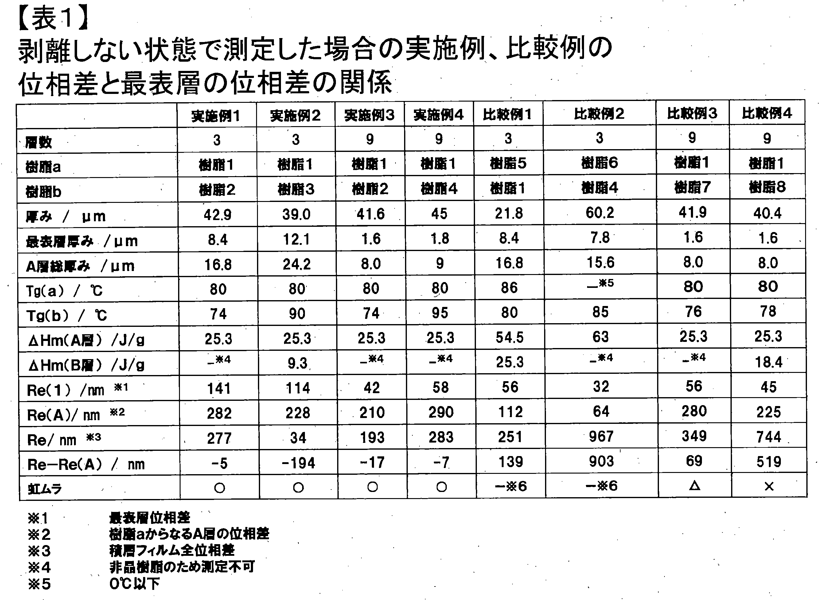


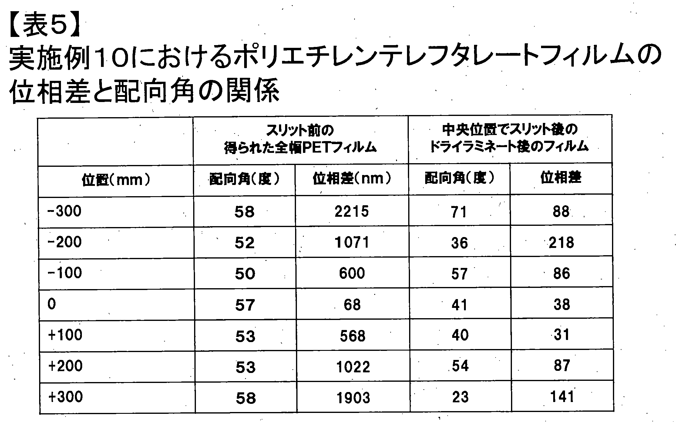
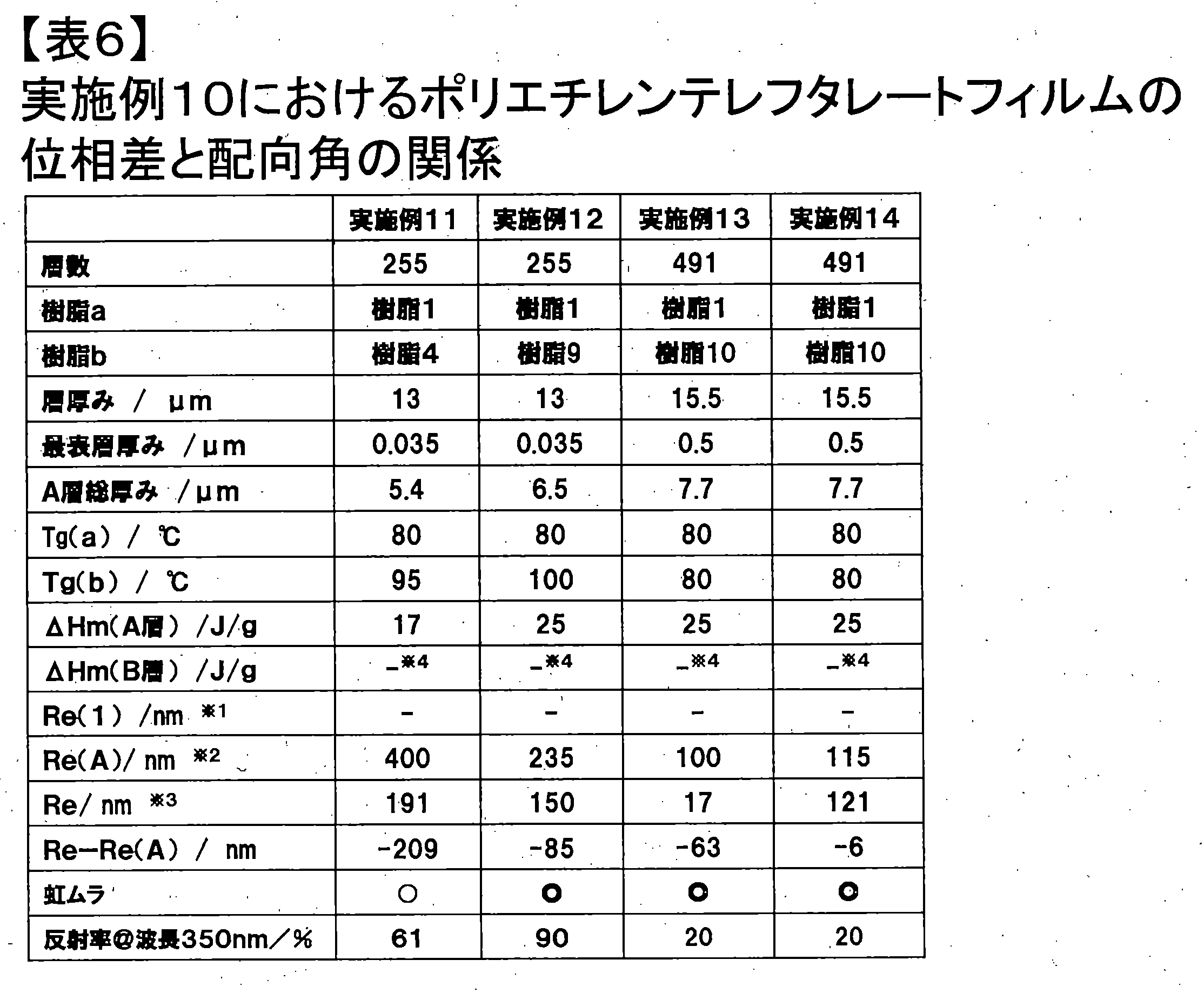

Claims (13)
- 二軸配向可能な結晶性樹脂aからなるA層と、前記結晶性樹脂aよりも結晶性の低い樹脂bからなるB層が、少なくとも3層以上交互に積層された多層積層フィルムであって、表層からk番目の層における位相差をRe(k)、全層数をnとしたときに、多層積層フィルムの全位相差Reが式(1)と式(2)を満たすことを特徴とする多層積層フィルム。


- 結晶性樹脂aからなるA層と、前記結晶性樹脂aよりも結晶性の低い樹脂bからなるB層が、少なくとも2層以上積層された第1の多層積層フィルムと、第2の多層積層フィルムと、順次、第k番目までの多層積層フィルムが重ね合わさった集合多層積層フィルムであって、k番目における多層積層フィルムの位相差をSRe(k)、全ての多層積層フィルムの数をnとしたときに、多層積層フィルムの集合体としての全位相差SReが式(3)を満たすことを特徴とする集合多層積層フィルム。kは自然数。
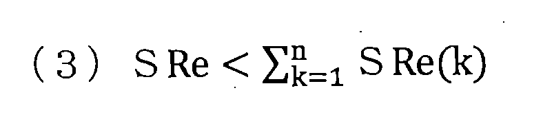
- 結晶性樹脂aからなるA層と、前記結晶性樹脂aよりも結晶性の低い樹脂bからなるB層が、少なくとも3層以上交互に積層された多層積層フィルムの上に、液晶材料を含んでなるC層が積層された複合多層積層フィルムであって、複合多層積層フィルムの全厚み方向の位相差Rth’と多層積層フィルムの全厚み方向位相差Rthが式(4)を満たすことを特徴とする複合多層積層フィルム。

- 二軸配向可能な結晶性樹脂aからなるA層と、前記結晶性樹脂aよりも結晶性の低い樹脂bからなるB層が、少なくとも3層以上交互に積層された多層積層フィルムであって、上記フィルムの最表層において、面内方向に最大の屈折率を与える方向の屈折率をNx(1)、それに垂直な方向の屈折率をNy(1)、最表層と同じ樹脂から構成される層の総厚みをd(A)、多層積層フィルムの全位相差をReとしたときに、式(5)を満たすことを特徴とする請求項1に記載の多層積層フィルム。

- 前記樹脂bがイソフタル酸、スピログリコール、イソソルビド、フルオレン、ビスフェノールA、シクロヘキンジメタノール成分からなる成分群のいずれかから選ばれた一つの成分以上を含む請求項1または4に記載の多層積層フィルム。
- 前記結晶性樹脂aがポリエチレンテレフタレート、ポリエチレンナフタレート、ポリブチレンテレフタレートからなる群から選ばれる一つである請求項1、4または5のいずれかに記載の多層積層フィルム。
- 前記結晶性樹脂aのガラス転移温度が、樹脂bのガラス転移温度より低い請求項1、4、5、または6のいずれかに記載の多層積層フィルム。
- 多層積層フィルムの長手方向に対する主配向軸の傾きが10~80°の多層積層フィルムであって、多層積層フィルムに含まれるA層の主配向軸とB層の主配向軸とがなす角度が、60~120°となる請求項1、4、5、6または7のいずれかに記載の多層積層フィルム。
- フィルム幅方向における位相差ムラが50nm/200mm以下である請求項1、4、5、6、7または8のいずれかに記載の多層積層フィルム。
- 波長350nmにおける反射率が20%以上である請求項1、4、5、6、7または9のいずれかに記載の多層積層フィルム。
- C層の厚み方向の屈折率NZと面内方向の屈折率NX, 、NYの関係が式(6)と式(7)を満足する請求項3に記載の複合多層積層フィルム。
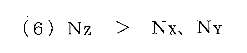

- C層の主配向軸φcと多層積層フィルムの主配向軸φabのなす狭角|φc-φab|が、50°~90°の関係にある請求項11に記載の複合多層積層フィルム。
- 光学用フィルムとして用いられる請求項1~12のいずれかに記載の多層積層フィルムまたは集合多層積層フィルムまたは複合多層積層フィルム。
Priority Applications (2)
| Application Number | Priority Date | Filing Date | Title |
|---|---|---|---|
| CN201680022018.9A CN107533175B (zh) | 2015-06-17 | 2016-06-14 | 多层层叠膜 |
| JP2016540086A JP6787126B2 (ja) | 2015-06-17 | 2016-06-14 | 多層積層フィルム |
Applications Claiming Priority (2)
| Application Number | Priority Date | Filing Date | Title |
|---|---|---|---|
| JP2015121851 | 2015-06-17 | ||
| JP2015-121851 | 2015-06-17 |
Publications (1)
| Publication Number | Publication Date |
|---|---|
| WO2016204146A1 true WO2016204146A1 (ja) | 2016-12-22 |
Family
ID=57546496
Family Applications (1)
| Application Number | Title | Priority Date | Filing Date |
|---|---|---|---|
| PCT/JP2016/067679 Ceased WO2016204146A1 (ja) | 2015-06-17 | 2016-06-14 | 多層積層フィルム |
Country Status (4)
| Country | Link |
|---|---|
| JP (1) | JP6787126B2 (ja) |
| CN (1) | CN107533175B (ja) |
| TW (1) | TWI730966B (ja) |
| WO (1) | WO2016204146A1 (ja) |
Cited By (3)
| Publication number | Priority date | Publication date | Assignee | Title |
|---|---|---|---|---|
| WO2019112020A1 (ja) * | 2017-12-06 | 2019-06-13 | 大日本印刷株式会社 | 電池用包装材料、電池、これらの製造方法、及びポリエステルフィルム |
| JPWO2022145238A1 (ja) * | 2020-12-28 | 2022-07-07 | ||
| JP2023048619A (ja) * | 2021-09-28 | 2023-04-07 | 日本ゼオン株式会社 | 多層光学フィルム及びその製造方法 |
Families Citing this family (2)
| Publication number | Priority date | Publication date | Assignee | Title |
|---|---|---|---|---|
| CN108943978B (zh) * | 2018-09-13 | 2023-09-19 | 东莞市赛越新材料科技有限公司 | 屏下指纹解锁保护膜的制作方法 |
| JP7088125B2 (ja) * | 2019-05-14 | 2022-06-21 | 信越半導体株式会社 | 被覆物の厚さ測定方法及び研削方法 |
Citations (6)
| Publication number | Priority date | Publication date | Assignee | Title |
|---|---|---|---|---|
| JP2004004905A (ja) * | 2003-06-23 | 2004-01-08 | Sumitomo Chem Co Ltd | 視野角補償用フィルムおよびこれを用いた液晶表示装置 |
| JP2004118185A (ja) * | 2002-09-06 | 2004-04-15 | Dainippon Printing Co Ltd | 積層位相差光学素子、その製造方法及び液晶表示装置 |
| JP4489145B2 (ja) * | 2007-06-01 | 2010-06-23 | 帝人株式会社 | 位相差フィルム、積層偏光フィルム、および液晶表示装置 |
| JP4849454B2 (ja) * | 2006-05-12 | 2012-01-11 | 日東電工株式会社 | 楕円偏光板およびそれを用いた画像表示装置 |
| JP2014012401A (ja) * | 2012-06-08 | 2014-01-23 | Toray Ind Inc | 多層積層フィルムおよびこれを用いたガラス窓部材 |
| WO2014188954A1 (ja) * | 2013-05-21 | 2014-11-27 | 東レ株式会社 | 積層フィルムおよび偏光板 |
Family Cites Families (7)
| Publication number | Priority date | Publication date | Assignee | Title |
|---|---|---|---|---|
| JP2006058540A (ja) * | 2004-08-19 | 2006-03-02 | Jsr Corp | 光学フィルム、偏光板および液晶ディスプレイ |
| JP2007065575A (ja) * | 2005-09-02 | 2007-03-15 | Jsr Corp | 光学フィルム、偏光板および液晶表示装置 |
| JP6174298B2 (ja) * | 2011-11-09 | 2017-08-02 | 住友化学株式会社 | 偏光性積層フィルムおよび積層フィルム |
| WO2014034521A1 (ja) * | 2012-08-30 | 2014-03-06 | 株式会社日本触媒 | 積層位相差フィルムおよびその製造方法 |
| JP6270812B2 (ja) * | 2013-02-28 | 2018-01-31 | 富士フイルム株式会社 | 位相差板、反射防止板、画像表示装置、および位相差板の製造方法 |
| WO2014171399A1 (ja) * | 2013-04-15 | 2014-10-23 | 富士フイルム株式会社 | 光学フィルム、光学フィルムの製造方法、偏光板、及び画像表示装置 |
| JP6627218B2 (ja) * | 2013-06-28 | 2020-01-08 | 東レ株式会社 | 二軸配向ポリエステルフィルム |
-
2016
- 2016-06-14 CN CN201680022018.9A patent/CN107533175B/zh active Active
- 2016-06-14 JP JP2016540086A patent/JP6787126B2/ja active Active
- 2016-06-14 WO PCT/JP2016/067679 patent/WO2016204146A1/ja not_active Ceased
- 2016-06-16 TW TW105118866A patent/TWI730966B/zh active
Patent Citations (6)
| Publication number | Priority date | Publication date | Assignee | Title |
|---|---|---|---|---|
| JP2004118185A (ja) * | 2002-09-06 | 2004-04-15 | Dainippon Printing Co Ltd | 積層位相差光学素子、その製造方法及び液晶表示装置 |
| JP2004004905A (ja) * | 2003-06-23 | 2004-01-08 | Sumitomo Chem Co Ltd | 視野角補償用フィルムおよびこれを用いた液晶表示装置 |
| JP4849454B2 (ja) * | 2006-05-12 | 2012-01-11 | 日東電工株式会社 | 楕円偏光板およびそれを用いた画像表示装置 |
| JP4489145B2 (ja) * | 2007-06-01 | 2010-06-23 | 帝人株式会社 | 位相差フィルム、積層偏光フィルム、および液晶表示装置 |
| JP2014012401A (ja) * | 2012-06-08 | 2014-01-23 | Toray Ind Inc | 多層積層フィルムおよびこれを用いたガラス窓部材 |
| WO2014188954A1 (ja) * | 2013-05-21 | 2014-11-27 | 東レ株式会社 | 積層フィルムおよび偏光板 |
Cited By (9)
| Publication number | Priority date | Publication date | Assignee | Title |
|---|---|---|---|---|
| WO2019112020A1 (ja) * | 2017-12-06 | 2019-06-13 | 大日本印刷株式会社 | 電池用包装材料、電池、これらの製造方法、及びポリエステルフィルム |
| JP6587039B1 (ja) * | 2017-12-06 | 2019-10-09 | 大日本印刷株式会社 | 電池用包装材料、電池、これらの製造方法、及びポリエステルフィルム |
| JP2020013796A (ja) * | 2017-12-06 | 2020-01-23 | 大日本印刷株式会社 | 電池用包装材料、電池、これらの製造方法、及びポリエステルフィルム |
| KR20200096494A (ko) * | 2017-12-06 | 2020-08-12 | 다이니폰 인사츠 가부시키가이샤 | 전지용 포장 재료, 전지, 이들의 제조 방법, 및 폴리에스테르 필름 |
| JP7234867B2 (ja) | 2017-12-06 | 2023-03-08 | 大日本印刷株式会社 | 電池用包装材料、電池、これらの製造方法、及びポリエステルフィルム |
| KR102827937B1 (ko) | 2017-12-06 | 2025-06-30 | 다이니폰 인사츠 가부시키가이샤 | 전지용 포장 재료, 전지, 이들의 제조 방법, 및 폴리에스테르 필름 |
| JPWO2022145238A1 (ja) * | 2020-12-28 | 2022-07-07 | ||
| JP2023048619A (ja) * | 2021-09-28 | 2023-04-07 | 日本ゼオン株式会社 | 多層光学フィルム及びその製造方法 |
| JP7615993B2 (ja) | 2021-09-28 | 2025-01-17 | 日本ゼオン株式会社 | 多層光学フィルム及びその製造方法 |
Also Published As
| Publication number | Publication date |
|---|---|
| TWI730966B (zh) | 2021-06-21 |
| CN107533175B (zh) | 2021-06-11 |
| JP6787126B2 (ja) | 2020-11-18 |
| JPWO2016204146A1 (ja) | 2018-04-05 |
| TW201710069A (zh) | 2017-03-16 |
| CN107533175A (zh) | 2018-01-02 |
Similar Documents
| Publication | Publication Date | Title |
|---|---|---|
| JP6453746B2 (ja) | 長尺状の光学積層体および画像表示装置 | |
| TWI297399B (ja) | ||
| JP5104373B2 (ja) | 位相差板の製造方法 | |
| TWI653136B (zh) | Laminated polyester film and polarizing plate using the same | |
| JP2018022060A (ja) | 長尺偏光フィルム及び液晶表示装置、エレクトレットルミネッセンス表示装置 | |
| JP2021081737A (ja) | 光学積層体 | |
| WO2016080342A1 (ja) | 積層フィルム | |
| JP5104439B2 (ja) | 位相差板 | |
| JP6479699B2 (ja) | 車両用画像表示機能付きミラーおよびその製造方法 | |
| JP6787126B2 (ja) | 多層積層フィルム | |
| WO2019182121A1 (ja) | エレクトロルミネッセンス表示装置 | |
| JP4557093B2 (ja) | 光学フィルム及び液晶表示装置 | |
| WO2020138368A1 (ja) | 位相差層付偏光板 | |
| TWI816867B (zh) | 附相位差層之偏光板及使用了該附相位差層之偏光板的影像顯示裝置 | |
| CN113874763A (zh) | 图像显示装置的制造方法和偏振片转印用层叠体 | |
| WO2015072486A1 (ja) | 位相差フィルムの製造方法 | |
| TWI832889B (zh) | 附相位差層之偏光板及使用了該附相位差層之偏光板的影像顯示裝置 | |
| JP6804168B2 (ja) | 位相差層付偏光板およびそれを用いた画像表示装置 | |
| TWI827658B (zh) | 附相位差層之偏光板及使用該附相位差層之偏光板的影像顯示裝置 | |
| JP5541273B2 (ja) | 位相差板の製造方法 | |
| JP5240103B2 (ja) | 積層位相差板、位相差板製造用フィルム及びそれを用いた積層位相差板の製造方法 | |
| TWI896775B (zh) | 附有相位差層之偏光板及圖像顯示裝置 | |
| WO2011018945A1 (ja) | 位相差板及びその製造方法並びに液晶表示装置 | |
| TWI827659B (zh) | 帶相位差層的偏光板及使用了該帶相位差層的偏光板的影像顯示裝置 | |
| JP2017067822A (ja) | 光学用ポリエステルフィルム及びそれを用いた偏光板、透明導電性フィルム |
Legal Events
| Date | Code | Title | Description |
|---|---|---|---|
| ENP | Entry into the national phase |
Ref document number: 2016540086 Country of ref document: JP Kind code of ref document: A |
|
| 121 | Ep: the epo has been informed by wipo that ep was designated in this application |
Ref document number: 16811620 Country of ref document: EP Kind code of ref document: A1 |
|
| NENP | Non-entry into the national phase |
Ref country code: DE |
|
| 122 | Ep: pct application non-entry in european phase |
Ref document number: 16811620 Country of ref document: EP Kind code of ref document: A1 |