WO2016204102A1 - 弁開閉時期制御装置 - Google Patents
弁開閉時期制御装置 Download PDFInfo
- Publication number
- WO2016204102A1 WO2016204102A1 PCT/JP2016/067478 JP2016067478W WO2016204102A1 WO 2016204102 A1 WO2016204102 A1 WO 2016204102A1 JP 2016067478 W JP2016067478 W JP 2016067478W WO 2016204102 A1 WO2016204102 A1 WO 2016204102A1
- Authority
- WO
- WIPO (PCT)
- Prior art keywords
- valve
- lock
- port
- control valve
- phase
- Prior art date
- Legal status (The legal status is an assumption and is not a legal conclusion. Google has not performed a legal analysis and makes no representation as to the accuracy of the status listed.)
- Ceased
Links
Images


Classifications
-
- F—MECHANICAL ENGINEERING; LIGHTING; HEATING; WEAPONS; BLASTING
- F01—MACHINES OR ENGINES IN GENERAL; ENGINE PLANTS IN GENERAL; STEAM ENGINES
- F01L—CYCLICALLY OPERATING VALVES FOR MACHINES OR ENGINES
- F01L1/00—Valve-gear or valve arrangements, e.g. lift-valve gear
- F01L1/34—Valve-gear or valve arrangements, e.g. lift-valve gear characterised by the provision of means for changing the timing of the valves without changing the duration of opening and without affecting the magnitude of the valve lift
- F01L1/344—Valve-gear or valve arrangements, e.g. lift-valve gear characterised by the provision of means for changing the timing of the valves without changing the duration of opening and without affecting the magnitude of the valve lift changing the angular relationship between crankshaft and camshaft, e.g. using helicoidal gear
- F01L1/356—Valve-gear or valve arrangements, e.g. lift-valve gear characterised by the provision of means for changing the timing of the valves without changing the duration of opening and without affecting the magnitude of the valve lift changing the angular relationship between crankshaft and camshaft, e.g. using helicoidal gear making the angular relationship oscillate, e.g. non-homokinetic drive
-
- F—MECHANICAL ENGINEERING; LIGHTING; HEATING; WEAPONS; BLASTING
- F01—MACHINES OR ENGINES IN GENERAL; ENGINE PLANTS IN GENERAL; STEAM ENGINES
- F01L—CYCLICALLY OPERATING VALVES FOR MACHINES OR ENGINES
- F01L1/00—Valve-gear or valve arrangements, e.g. lift-valve gear
- F01L1/34—Valve-gear or valve arrangements, e.g. lift-valve gear characterised by the provision of means for changing the timing of the valves without changing the duration of opening and without affecting the magnitude of the valve lift
- F01L1/344—Valve-gear or valve arrangements, e.g. lift-valve gear characterised by the provision of means for changing the timing of the valves without changing the duration of opening and without affecting the magnitude of the valve lift changing the angular relationship between crankshaft and camshaft, e.g. using helicoidal gear
- F01L1/3442—Valve-gear or valve arrangements, e.g. lift-valve gear characterised by the provision of means for changing the timing of the valves without changing the duration of opening and without affecting the magnitude of the valve lift changing the angular relationship between crankshaft and camshaft, e.g. using helicoidal gear using hydraulic chambers with variable volume to transmit the rotating force
-
- F—MECHANICAL ENGINEERING; LIGHTING; HEATING; WEAPONS; BLASTING
- F02—COMBUSTION ENGINES; HOT-GAS OR COMBUSTION-PRODUCT ENGINE PLANTS
- F02D—CONTROLLING COMBUSTION ENGINES
- F02D13/00—Controlling the engine output power by varying inlet or exhaust valve operating characteristics, e.g. timing
- F02D13/02—Controlling the engine output power by varying inlet or exhaust valve operating characteristics, e.g. timing during engine operation
- F02D13/06—Cutting-out cylinders
-
- F—MECHANICAL ENGINEERING; LIGHTING; HEATING; WEAPONS; BLASTING
- F01—MACHINES OR ENGINES IN GENERAL; ENGINE PLANTS IN GENERAL; STEAM ENGINES
- F01L—CYCLICALLY OPERATING VALVES FOR MACHINES OR ENGINES
- F01L1/00—Valve-gear or valve arrangements, e.g. lift-valve gear
- F01L1/02—Valve drive
- F01L1/04—Valve drive by means of cams, camshafts, cam discs, eccentrics or the like
- F01L1/047—Camshafts
-
- F—MECHANICAL ENGINEERING; LIGHTING; HEATING; WEAPONS; BLASTING
- F01—MACHINES OR ENGINES IN GENERAL; ENGINE PLANTS IN GENERAL; STEAM ENGINES
- F01L—CYCLICALLY OPERATING VALVES FOR MACHINES OR ENGINES
- F01L1/00—Valve-gear or valve arrangements, e.g. lift-valve gear
- F01L1/34—Valve-gear or valve arrangements, e.g. lift-valve gear characterised by the provision of means for changing the timing of the valves without changing the duration of opening and without affecting the magnitude of the valve lift
- F01L1/344—Valve-gear or valve arrangements, e.g. lift-valve gear characterised by the provision of means for changing the timing of the valves without changing the duration of opening and without affecting the magnitude of the valve lift changing the angular relationship between crankshaft and camshaft, e.g. using helicoidal gear
- F01L1/3442—Valve-gear or valve arrangements, e.g. lift-valve gear characterised by the provision of means for changing the timing of the valves without changing the duration of opening and without affecting the magnitude of the valve lift changing the angular relationship between crankshaft and camshaft, e.g. using helicoidal gear using hydraulic chambers with variable volume to transmit the rotating force
- F01L2001/34423—Details relating to the hydraulic feeding circuit
- F01L2001/34426—Oil control valves
- F01L2001/3443—Solenoid driven oil control valves
-
- F—MECHANICAL ENGINEERING; LIGHTING; HEATING; WEAPONS; BLASTING
- F01—MACHINES OR ENGINES IN GENERAL; ENGINE PLANTS IN GENERAL; STEAM ENGINES
- F01L—CYCLICALLY OPERATING VALVES FOR MACHINES OR ENGINES
- F01L1/00—Valve-gear or valve arrangements, e.g. lift-valve gear
- F01L1/34—Valve-gear or valve arrangements, e.g. lift-valve gear characterised by the provision of means for changing the timing of the valves without changing the duration of opening and without affecting the magnitude of the valve lift
- F01L1/344—Valve-gear or valve arrangements, e.g. lift-valve gear characterised by the provision of means for changing the timing of the valves without changing the duration of opening and without affecting the magnitude of the valve lift changing the angular relationship between crankshaft and camshaft, e.g. using helicoidal gear
- F01L1/3442—Valve-gear or valve arrangements, e.g. lift-valve gear characterised by the provision of means for changing the timing of the valves without changing the duration of opening and without affecting the magnitude of the valve lift changing the angular relationship between crankshaft and camshaft, e.g. using helicoidal gear using hydraulic chambers with variable volume to transmit the rotating force
- F01L2001/34423—Details relating to the hydraulic feeding circuit
- F01L2001/34426—Oil control valves
- F01L2001/34433—Location oil control valves
-
- F—MECHANICAL ENGINEERING; LIGHTING; HEATING; WEAPONS; BLASTING
- F01—MACHINES OR ENGINES IN GENERAL; ENGINE PLANTS IN GENERAL; STEAM ENGINES
- F01L—CYCLICALLY OPERATING VALVES FOR MACHINES OR ENGINES
- F01L1/00—Valve-gear or valve arrangements, e.g. lift-valve gear
- F01L1/34—Valve-gear or valve arrangements, e.g. lift-valve gear characterised by the provision of means for changing the timing of the valves without changing the duration of opening and without affecting the magnitude of the valve lift
- F01L1/344—Valve-gear or valve arrangements, e.g. lift-valve gear characterised by the provision of means for changing the timing of the valves without changing the duration of opening and without affecting the magnitude of the valve lift changing the angular relationship between crankshaft and camshaft, e.g. using helicoidal gear
- F01L1/3442—Valve-gear or valve arrangements, e.g. lift-valve gear characterised by the provision of means for changing the timing of the valves without changing the duration of opening and without affecting the magnitude of the valve lift changing the angular relationship between crankshaft and camshaft, e.g. using helicoidal gear using hydraulic chambers with variable volume to transmit the rotating force
- F01L2001/3445—Details relating to the hydraulic means for changing the angular relationship
-
- F—MECHANICAL ENGINEERING; LIGHTING; HEATING; WEAPONS; BLASTING
- F01—MACHINES OR ENGINES IN GENERAL; ENGINE PLANTS IN GENERAL; STEAM ENGINES
- F01L—CYCLICALLY OPERATING VALVES FOR MACHINES OR ENGINES
- F01L1/00—Valve-gear or valve arrangements, e.g. lift-valve gear
- F01L1/34—Valve-gear or valve arrangements, e.g. lift-valve gear characterised by the provision of means for changing the timing of the valves without changing the duration of opening and without affecting the magnitude of the valve lift
- F01L1/344—Valve-gear or valve arrangements, e.g. lift-valve gear characterised by the provision of means for changing the timing of the valves without changing the duration of opening and without affecting the magnitude of the valve lift changing the angular relationship between crankshaft and camshaft, e.g. using helicoidal gear
- F01L1/3442—Valve-gear or valve arrangements, e.g. lift-valve gear characterised by the provision of means for changing the timing of the valves without changing the duration of opening and without affecting the magnitude of the valve lift changing the angular relationship between crankshaft and camshaft, e.g. using helicoidal gear using hydraulic chambers with variable volume to transmit the rotating force
- F01L2001/3445—Details relating to the hydraulic means for changing the angular relationship
- F01L2001/34453—Locking means between driving and driven members
- F01L2001/34463—Locking position intermediate between most retarded and most advanced positions
-
- F—MECHANICAL ENGINEERING; LIGHTING; HEATING; WEAPONS; BLASTING
- F01—MACHINES OR ENGINES IN GENERAL; ENGINE PLANTS IN GENERAL; STEAM ENGINES
- F01L—CYCLICALLY OPERATING VALVES FOR MACHINES OR ENGINES
- F01L1/00—Valve-gear or valve arrangements, e.g. lift-valve gear
- F01L1/34—Valve-gear or valve arrangements, e.g. lift-valve gear characterised by the provision of means for changing the timing of the valves without changing the duration of opening and without affecting the magnitude of the valve lift
- F01L1/344—Valve-gear or valve arrangements, e.g. lift-valve gear characterised by the provision of means for changing the timing of the valves without changing the duration of opening and without affecting the magnitude of the valve lift changing the angular relationship between crankshaft and camshaft, e.g. using helicoidal gear
- F01L1/3442—Valve-gear or valve arrangements, e.g. lift-valve gear characterised by the provision of means for changing the timing of the valves without changing the duration of opening and without affecting the magnitude of the valve lift changing the angular relationship between crankshaft and camshaft, e.g. using helicoidal gear using hydraulic chambers with variable volume to transmit the rotating force
- F01L2001/3445—Details relating to the hydraulic means for changing the angular relationship
- F01L2001/34453—Locking means between driving and driven members
- F01L2001/34473—Lock movement perpendicular to camshaft axis
-
- F—MECHANICAL ENGINEERING; LIGHTING; HEATING; WEAPONS; BLASTING
- F01—MACHINES OR ENGINES IN GENERAL; ENGINE PLANTS IN GENERAL; STEAM ENGINES
- F01L—CYCLICALLY OPERATING VALVES FOR MACHINES OR ENGINES
- F01L1/00—Valve-gear or valve arrangements, e.g. lift-valve gear
- F01L1/34—Valve-gear or valve arrangements, e.g. lift-valve gear characterised by the provision of means for changing the timing of the valves without changing the duration of opening and without affecting the magnitude of the valve lift
- F01L1/344—Valve-gear or valve arrangements, e.g. lift-valve gear characterised by the provision of means for changing the timing of the valves without changing the duration of opening and without affecting the magnitude of the valve lift changing the angular relationship between crankshaft and camshaft, e.g. using helicoidal gear
- F01L1/3442—Valve-gear or valve arrangements, e.g. lift-valve gear characterised by the provision of means for changing the timing of the valves without changing the duration of opening and without affecting the magnitude of the valve lift changing the angular relationship between crankshaft and camshaft, e.g. using helicoidal gear using hydraulic chambers with variable volume to transmit the rotating force
- F01L2001/3445—Details relating to the hydraulic means for changing the angular relationship
- F01L2001/34483—Phaser return springs
-
- F—MECHANICAL ENGINEERING; LIGHTING; HEATING; WEAPONS; BLASTING
- F01—MACHINES OR ENGINES IN GENERAL; ENGINE PLANTS IN GENERAL; STEAM ENGINES
- F01L—CYCLICALLY OPERATING VALVES FOR MACHINES OR ENGINES
- F01L2250/00—Camshaft drives characterised by their transmission means
- F01L2250/02—Camshaft drives characterised by their transmission means the camshaft being driven by chains
-
- F—MECHANICAL ENGINEERING; LIGHTING; HEATING; WEAPONS; BLASTING
- F01—MACHINES OR ENGINES IN GENERAL; ENGINE PLANTS IN GENERAL; STEAM ENGINES
- F01L—CYCLICALLY OPERATING VALVES FOR MACHINES OR ENGINES
- F01L2800/00—Methods of operation using a variable valve timing mechanism
-
- F—MECHANICAL ENGINEERING; LIGHTING; HEATING; WEAPONS; BLASTING
- F02—COMBUSTION ENGINES; HOT-GAS OR COMBUSTION-PRODUCT ENGINE PLANTS
- F02D—CONTROLLING COMBUSTION ENGINES
- F02D13/00—Controlling the engine output power by varying inlet or exhaust valve operating characteristics, e.g. timing
- F02D13/02—Controlling the engine output power by varying inlet or exhaust valve operating characteristics, e.g. timing during engine operation
-
- Y—GENERAL TAGGING OF NEW TECHNOLOGICAL DEVELOPMENTS; GENERAL TAGGING OF CROSS-SECTIONAL TECHNOLOGIES SPANNING OVER SEVERAL SECTIONS OF THE IPC; TECHNICAL SUBJECTS COVERED BY FORMER USPC CROSS-REFERENCE ART COLLECTIONS [XRACs] AND DIGESTS
- Y02—TECHNOLOGIES OR APPLICATIONS FOR MITIGATION OR ADAPTATION AGAINST CLIMATE CHANGE
- Y02T—CLIMATE CHANGE MITIGATION TECHNOLOGIES RELATED TO TRANSPORTATION
- Y02T10/00—Road transport of goods or passengers
- Y02T10/10—Internal combustion engine [ICE] based vehicles
- Y02T10/12—Improving ICE efficiencies
Definitions
- the present invention controls the relative rotation phase between the drive-side rotator and the driven-side rotator, and the control of the lock mechanism that restrains the drive-side rotator and the driven-side rotator at a predetermined relative rotation phase, using the working fluid.
- the present invention relates to a valve opening / closing timing control device.
- Patent Document 1 discloses an electromagnetic that accommodates a spool that operates along the axis of the driven rotary body connected to a camshaft and operates the spool.
- the technology of an oil control valve provided with a solenoid outside the rotating system is shown.
- a port that communicates with the advance chamber and the retard chamber inside the valve opening / closing timing control device so as to control the relative rotation phase by the operation of the spool and control the lock mechanism, and the lock member of the lock mechanism A port communicating with the port is formed.
- Patent Document 2 discloses a working fluid for a lock mechanism and a first switching valve that controls a relative rotational phase of a driving side rotating body and a driven side rotating body by supplying and discharging working fluid to and from an advance chamber and a retard chamber.
- a technology including a second switching valve that controls the lock mechanism by supplying and discharging the gas is shown.
- the first switching valve and the second switching valve are configured as electromagnetic valves that are controlled by supplying and discharging electric power to and from the electromagnetic solenoid, and these are arranged outside the driving side rotating body and the driven side rotating body. It is.
- Patent Document 3 the relative rotation phase between the driving side rotating body and the driven side rotating body is controlled by controlling the fluid with a control valve in which a spool is arranged coaxially with the camshaft.
- a technique for controlling the exit and withdrawal of a lock pin by controlling a fluid with a pilot valve provided inside is shown.
- JP 2015-78635 A Japanese Patent No. 5267264 Special table 2011-513651 gazette
- the valve opening / closing timing control device has a configuration in which the relative rotation phase is displaced by supplying and discharging the working fluid to and from the advance chamber and the retard chamber, and the lock mechanism is controlled by supplying and discharging hydraulic fluid to and from the flow path that controls the lock mechanism. It has the structure which controls a locked state.
- control valve with a linearly acting spool to realize these controls.
- the pump port to which the working fluid is supplied from the fluid pressure pump, the drain port for discharging the fluid, the advance port communicating with the advance chamber, and the retard port communicating with the retard chamber A plurality of ports with a lock port communicating with the lock channel are required.
- the pump port, the advance port, the retard port, and the lock port are arranged at predetermined intervals along the operation direction of the spool.
- valve opening / closing timing control device that realizes control of the relative rotation phase and control of the lock mechanism with a small control valve is required.
- the characteristic configuration of the valve opening / closing timing control device includes a drive side rotating body that rotates synchronously with a crankshaft of the internal combustion engine, and a camshaft for opening / closing the valve of the internal combustion engine that is arranged coaxially with the rotation axis of the drive side rotating body.
- a driven-side rotating body that rotates integrally with the drive-side rotating body, and a fluid pressure chamber defined between the driving-side rotating body and the driven-side rotating body, as either the driving-side rotating body or the driven-side rotating body.
- a lock state or restriction that restricts the relative rotation phase of the driven-side rotator with respect to the drive-side rotator to a predetermined lock phase and the advance chamber and retard chamber formed by partitioning with the formed partition portion A lock mechanism that can be switched to an unlocked state, a first valve whose position is switched electromagnetically, and a second valve whose position is switched by the fluid pressure controlled by the first valve, from a fluid pressure pump Supplying a working fluid to be supplied to the advance chamber or the retard chamber to control the relative rotation phase; and supplying a working fluid supplied from the fluid pressure pump to the lock mechanism.
- At least one of the lock control valve for controlling the lock state of the lock mechanism is configured as the second valve.
- the working fluid from the fluid pressure pump is directly supplied from the phase control valve in conjunction with the operation of the first valve.
- the relative rotation phase can be controlled by supplying the advance chamber or the retard chamber.
- the hydraulic oil from the fluid pressure pump is directly supplied to the lock mechanism in conjunction with the operation of the first valve.
- Lock state can be controlled. That is, it is only necessary to form a port that requires a small flow passage area for applying fluid pressure to the first valve.
- the first valve is configured to control the relative rotation phase and the lock mechanism.
- a port for supplying and discharging the working fluid to the advance chamber or the retard chamber and a port for supplying and discharging the working fluid to the lock mechanism are not required, and the valve can be downsized. Further, as compared with the second valve whose position is switched electromagnetically, an electromagnetic solenoid is not required, and the configuration is simple and inexpensive. Therefore, a valve opening / closing timing control device that realizes the control of the relative rotation phase and the control of the lock mechanism with a small control valve is configured.
- the lock control valve may be provided as the second valve whose position is switched by the fluid pressure from the pilot pressure port.
- the first valve may be configured such that the advance port and the retard port are arranged in parallel, and the pilot pressure port is arranged at a position next to the advance port and the retard port. good.
- At least one of a flow path for supplying the working fluid from the fluid pressure pump to the first valve and a flow path for supplying the working fluid from the fluid pressure pump to the second valve One side may be provided with a check valve.
- the pressure of the working fluid temporarily decreases. Even in this case, the smooth operation can be maintained by suppressing the pressure drop of the flow path provided with the check valve.
- the lock mechanism is formed on the driven-side rotator so that the lock member engages with a lock member that is projected and urged by a lock urging member with respect to the drive-side rotator.
- the driven-side rotating body is connected to the camshaft by a connecting bolt, and the lock control valve is provided at a location other than the connecting bolt in the driven-side rotating body. May be provided.
- the lock control valve at a location other than the connecting bolt in the driven side rotating body, the working fluid can be supplied and discharged from a position close to the lock mechanism.
- the lock control valve is disposed at a position away from the rotation axis, it is possible to provide a phase control valve on the rotation axis.
- the lock control valve includes a valve body that is movably inserted into a hole formed along the shaft core in a posture parallel to the rotation shaft core in the driven-side rotating body. It may be configured.
- this centrifugal force acts in a direction orthogonal to the moving direction of the valve body. It does not move and supply / discharge the working fluid to / from the lock mechanism.
- a lock release flow path for releasing the lock by supplying a working fluid from the lock control valve to the lock mechanism, and a lock state by discharging the working fluid from the lock mechanism via the lock control valve
- a lock drain flow path for maintaining the pressure control valve and a pilot flow path for applying a pilot pressure to the lock control valve are formed in the driven side rotating body, the unlocking flow path, the lock drain flow path,
- the pilot flow paths may be arranged in parallel in this order.
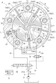
- FIG. 3 is a sectional view taken along line III-III in FIG. 1.
- FIG. 4 is a sectional view taken along line IV-IV in FIG. 2. It is a figure which shows the relationship between each position of a phase control valve, and a port. It is a figure which shows the valve opening / closing timing control apparatus of another embodiment (a). It is a figure which shows the valve opening / closing timing control apparatus of another embodiment (b).
- an external rotor 20 (an example of a drive side rotating body) that rotates synchronously with a crankshaft 1 of an engine E as an internal combustion engine, and an intake camshaft 5 of a combustion chamber of the engine E rotate integrally.
- the valve opening / closing timing control device A is configured to include an internal rotor 30 (an example of a driven side rotating body) that is relatively rotatable about the rotation axis X of the intake camshaft 5.
- the valve opening / closing timing control device A includes an internal rotor 30 (driven side rotary body) with respect to the external rotor 20 (drive side rotary body), and a rotational axis X and a coaxial core at the center position of the internal rotor 30.
- an electromagnetic phase control valve 40 as a first valve.
- the internal rotor 30 is connected to the intake camshaft 5 by a connecting bolt 38 disposed on the same axis as the rotational axis X, and a pilot pressure operation as a second valve is performed at a position outward from the connecting bolt 38.
- a lock control valve 50 of the type is provided.
- the first valve that is electromagnetically switched in position has the function of the phase control valve 40, so that the first valve is also used as the phase control valve 40 and is controlled by the first valve.
- a lock control valve 50 is provided as a specific example of the second valve whose position is switched by hydraulic pressure (fluid pressure).
- the valve opening / closing timing control device A controls the electric power supplied from the control unit G functioning as an ECU to the electromagnetic solenoid 44 of the phase control valve 40 (an example of the first valve), whereby the phase control valve 40 (first valve). ) Can be switched to multiple positions.
- the hydraulic oil (an example of the working fluid) from the hydraulic pump P (an example of the fluid pressure pump) is controlled to change the relative rotational phase (hereinafter referred to as a relative rotational phase) between the external rotor 20 and the internal rotor 30.
- a relative rotational phase relative rotational phase
- the phase control valve 40 is also configured to control the pilot pressure (fluid pressure) by being set at a plurality of positions, and the lock control valve 50 (second valve) is controlled as shown in FIG. Switching between the position and the unlock position shown in FIG. Thereby, the hydraulic fluid from the hydraulic pump P (fluid pressure pump) is controlled to control the lock state of the lock mechanism L.
- An engine E (an example of an internal combustion engine) is provided in a vehicle such as a passenger car.
- the engine E includes a crankshaft 1 at the lower portion, accommodates a piston 3 in a cylinder bore formed in a cylinder block 2 at an upper position of the crankshaft 1, and connects the piston 3 and the crankshaft 1 by a connecting rod 4. 4 cycle type.
- the engine E is provided with an intake camshaft 5 that opens and closes an intake valve 5V and an exhaust camshaft that opens and closes an exhaust valve.
- the engine E includes a hydraulic pump P that is driven by the driving force of the crankshaft 1. (An example of a fluid pressure pump).
- the hydraulic pump P uses lubricating oil stored in an oil pan of the engine E as hydraulic oil, and supplies the hydraulic oil to the phase control valve 40 and the lock control valve 50 via the supply flow path 8.
- the timing chain 7 is wound around the output sprocket 6 formed on the crankshaft 1 of the engine E and the timing sprocket 23P. As a result, the external rotor 20 rotates in synchronization with the crankshaft 1.
- a timing sprocket is also provided at the front end of the camshaft on the exhaust side, and the timing chain 7 is wound around this sprocket.
- the external rotor 20 rotates in the driving rotation direction S by the driving force of the crankshaft 1.
- the direction in which the inner rotor 30 rotates relative to the outer rotor 20 in the same direction as the drive rotation direction S is referred to as an advance angle direction Sa, and the opposite direction is referred to as a retard angle direction Sb.
- the intake compression ratio is increased as the displacement amount is increased, and when the relative rotational phase is displaced in the retard direction Sb, the displacement amount is increased.
- the relationship between the crankshaft 1 and the intake camshaft 5 is set so as to reduce the intake compression ratio as it increases.
- valve opening / closing timing control device A is provided on the intake camshaft 5.
- valve opening / closing timing control device A is provided on the exhaust camshaft, and both the intake camshaft 5 and the exhaust camshaft are provided. You may be prepared for.
- the external rotor 20 has an external rotor main body 21, a front plate 22, and a rear plate 23, which are integrated by fastening a plurality of fastening bolts 24. Yes. By this fastening, the internal rotor 30 is disposed at a position sandwiched between the front plate 22 and the rear plate 23. A timing sprocket 23 ⁇ / b> P is formed on the outer periphery of the rear plate 23.
- the outer rotor main body 21 is integrally formed with a plurality of protruding walls 21T that protrude inward in the radial direction with respect to the rotation axis X. Further, the inner rotor 30 is provided on the outer periphery of the inner rotor body 31 so as to come into contact with a cylindrical inner rotor body 31 that is in close contact with the projecting end of the projecting wall 21T of the outer rotor body 21 and the inner peripheral surface of the outer rotor body 21 And a plurality of (four) vanes 32 provided in a protruding manner.
- a plurality of fluid pressure chambers C are formed on the outer peripheral side of the internal rotor body 31 at an intermediate position between the protruding walls 21T adjacent in the rotational direction. Then, the advance chamber Ca and the retard chamber Cb are formed by partitioning these fluid pressure chambers C with vanes 32 (an example of a partition).
- the inner rotor 30 is formed with a hole centered on the rotation axis X, and a connecting bolt 38 made of steel is inserted into the hole.
- the connecting bolt 38 is formed with a bolt head 38 ⁇ / b> H and a male screw portion 38 ⁇ / b> S.
- the male screw portion 38 ⁇ / b> S is screwed into the female screw portion of the intake camshaft 5, whereby the internal rotor 30 is connected to the intake camshaft 5.
- the connecting bolt 38 is formed in a cylindrical shape centered on the rotation axis X, and the phase control spool 41 of the phase control valve 40 is accommodated in this internal space.
- the configuration of the phase control valve 40 will be described later.
- the lock mechanism L is a plate-like lock member 26 that is supported so as to be movable in and out in the radial direction with respect to the lock recess 25 formed on the outer periphery of the inner rotor body 31 of the inner rotor 30 and the protruding wall 21T of the outer rotor 20.
- a lock spring 27 (an example of a lock urging member) that urges the lock member 26 toward the lock recess 25.
- the lock mechanism L constrains the relative rotation phase to the intermediate lock phase by engaging the tip of the lock member 26 with the lock recess 25.
- a phase that reaches the lock state at a phase such as the most retarded phase or the most advanced angle phase may be used.
- the lock mechanism L the state in which the hydraulic oil is supplied to the lock recess 25 is maintained, so that the lock member 26 is maintained in the unlocked state in which the lock member 26 is detached from the lock recess 25.
- the relative rotational phase when the vane 32 has reached the working end in the advance direction Sa (including the phase near the working end of the vane 32 in the advance direction Sa) is the most advanced angle phase.
- the relative rotational phase in the state where the operating end in the retarding direction Sb (including the phase near the operating end of the vane 32 in the retarding direction Sb) is reached is the most retarded phase.
- a torsion spring 16 supported by a spring holder 15 is provided so that an urging force acts on the relative rotational phase between the outer rotor 20 and the inner rotor 30 from the most retarded phase to the intermediate lock phase. ing.
- the spring holder 15 has its bottom wall 15a fitted to the internal rotor 30, and the cylindrical holder body 15b protrudes outward.
- the torsion spring 16 is disposed in a region surrounding the holder main body 15b, and has a base end portion engaged with the front plate 22 and a tip end portion engaged with the holder main body 15b. As a result, the torsion spring 16 applies a biasing force in a direction from the most retarded phase to the intermediate phase.
- the internal rotor body 31 is formed with an advance passage 33 that communicates with the advance chamber Ca and a retard passage 34 that communicates with the retard chamber Cb. Further, the inner rotor body 31 is formed with an unlock passage 35 and a lock drain passage 36 that communicate with the lock recess 25.
- the lock drain channel 36 communicates with a drain channel 36 a that discharges hydraulic fluid from the lock control valve 50. Further, a pilot flow path 37 for operating the lock control valve 50 is formed in the inner rotor body 31.
- a supply flow path 8 for supplying hydraulic oil from the hydraulic pump P is connected to the intake camshaft 5 so as to be relatively rotatable so as to be relatively rotatable. Communicating with
- a supply space 11 communicating with the annular space 10 (supply flow path 8) is formed inside the connecting bolt 38.
- the connection bolt 38 is provided with a main check valve CVa composed of a spring and a ball so as to be opened as the pressure in the supply space 11 rises to supply hydraulic oil to the first pump passage 12.
- a second pump flow path 13 to which hydraulic fluid in the annular space 10 (supply flow path 8) is supplied and a lock release flow path 35 are formed.
- the second pump flow path 13 is formed in the connecting bolt 38.
- the lock release passage 35 is formed in a region extending from the intake camshaft 5 to the inner rotor body 31, and the lock release passage 35 is provided with a lock check valve CVb for preventing the backflow of hydraulic oil. Further, as shown in FIGS. 3 and 4 (not shown in FIGS. 1 and 2), for maintaining the pilot pressure in the second pump passage 13 to which the hydraulic oil from the hydraulic pump P is supplied. A check valve CVc is provided.
- phase control valve 40 and the lock control valve 50 are shown in cross section, and at the same time, the phase control valve 40 and the lock control valve 50 are shown by symbols in the hydraulic circuit.
- FIG. 6 a the lock control valve 50 is shown in cross section, and at the same time, the lock control valve 50 is shown by a symbol in the hydraulic circuit.
- the phase control valve 40 includes a phase control spool 41, a spool spring 42, and an electromagnetic solenoid 44.
- the phase control spool 41 is slidably disposed in a direction along the rotation axis X in the internal space of the connecting bolt 38.
- the connecting bolt 38 is provided with a stopper 43 formed of a retaining ring for determining an operation position on the outer end side of the phase control spool 41.
- the spool spring 42 applies a biasing force in a direction in which the phase control spool 41 is separated from the intake camshaft 5.
- the electromagnetic solenoid 44 is disposed outside the valve opening / closing timing control device A, and includes a plunger 44a that protrudes and operates in an amount proportional to the electric power supplied to the internal solenoid. The pressing force of the plunger 44a Thus, the phase control spool 41 is operated.
- phase control spool 41 and the spool spring 42 rotate integrally with the internal rotor 30, and the electromagnetic solenoid 44 is supported by the engine E so as not to rotate.
- phase control spool 41 The inside of the phase control spool 41 is formed hollow, and a drain hole 41D communicating with the internal space is formed at the protruding end of the phase control spool 41.
- a first groove portion 41A that can communicate with the first pump flow path 12 and a second groove portion 41B that can communicate with the second pump flow path 13 are grooved over the entire circumference. Is formed.
- a first drain hole 41E communicating with the internal space of the phase control spool 41 is formed at an intermediate position between the first groove portion 41A and the second groove portion 41B.
- connection bolt 38 is formed with an advance port 38 a that communicates with the advance channel 33, a retard port 38 b that communicates with the retard channel 34, and a pilot pressure port 38 c that communicates with the pilot channel 37. Yes.
- phase control valve 40 As shown in FIGS. 3 to 5, power is not supplied to the electromagnetic solenoid 44, and the phase control spool 40 is in a state where the pressing force of the plunger 44a of the electromagnetic solenoid 44 does not act (see FIG. 1). 41 is held at the first control position Q1. And with the increase in the amount of electric power (electric power) supplied to the electromagnetic solenoid 44, the second control position Q2, the third control position Q3, the fourth control position Q4, and the fifth control position Q5 are held.
- the lock control valve 50 is configured to be a two-position switching type between the lock position and the unlock position, and is located outward from the central connection bolt 38 in the internal rotor 30 (from the rotational axis X other than the connection bolt 38). (Position to be separated).
- the lock control valve 50 is slidably accommodated in a spool hole (an example of a hole) formed in a position parallel to the rotation axis X at a position near the lock recess 25 in the internal rotor 30.
- a lock control spool 51 an example of a valve body
- a return spring 52 are provided.
- the lock control spool 51 has a land portion at both end positions by forming a groove portion having a groove shape over the entire circumference at a central position in the longitudinal direction.
- the lock release channel 35 and the lock drain channel 36 are connected to the spool hole at different positions. Further, the pilot flow path 37 communicates with the end of the spool hole opposite to the end where the return spring 52 is disposed.
- hydraulic oil supplied from the hydraulic pump P to the first groove portion 41A is supplied from the retard port 38b to the retard chamber Cb via the retard channel 34.
- the hydraulic oil is discharged from the advance chamber Ca to the first drain hole 41E from the advance port 38a through the advance channel 33.
- the hydraulic oil supplied from the hydraulic pump P to the second groove portion 41B does not flow to the pilot pressure port 38c, and the pilot pressure port 38c passes through the inner end portion of the phase control spool 41 to Since the pilot pressure in the pilot flow path 37 is low (zero pressure) because it communicates with the internal space, the lock control spool 51 is held at the lock position as shown in FIG.
- the lock drain channel 36 communicates with the drain channel 36a while the lock release channel 35 is closed, so that the lock mechanism L reaches a state where it can shift to the locked state. Therefore, when the lock mechanism L is already in the locked state, the locked state is maintained. Further, when the lock mechanism L is not in the locked state, the lock member 26 is fitted into the lock recess 25 by the urging force of the lock spring 27 at the timing when the relative rotation phase reaches the intermediate lock phase, and the lock mechanism L Transition to the locked state.
- the hydraulic oil supplied from the hydraulic pump P to the first groove portion 41A is supplied from the retard port 38b to the retard chamber Cb via the retard channel 34.
- the hydraulic oil in the advance chamber Ca is discharged from the advance port 38a to the first drain hole 41E through the advance channel 33.
- the unlocking channel 35 reaches a communicating state and the lock drain channel 36 is closed, so that hydraulic oil is supplied to the locking recess 25.
- the lock member 26 is separated from the lock recess 25 against the urging force of the lock spring 27 to release the lock state of the lock mechanism L, and the hydraulic oil supplied from the hydraulic pump P to the retard chamber Cb makes the relative movement.
- the rotational phase is displaced in the retarding direction Sb.
- the hydraulic oil supplied from the hydraulic pump P to the first groove portion 41A is supplied from the advance port 38a to the advance chamber Ca via the advance channel 33.
- the hydraulic oil in the retard chamber Cb is discharged from the retard port 38b to the front end side of the phase control spool 41 through the retard channel 34.
- the unlocking channel 35 reaches a communicating state and the lock drain channel 36 is closed, so that hydraulic oil is supplied to the locking recess 25.
- the lock member 26 is separated from the lock recess 25 against the urging force of the lock spring 27 to release the lock state of the lock mechanism L, and the hydraulic oil supplied from the hydraulic pump P to the advance chamber Ca makes the relative movement.
- the rotational phase is displaced in the advance direction Sa.
- the hydraulic oil supplied from the hydraulic pump P to the first groove portion 41A is supplied from the advance port 38a to the advance chamber Ca via the advance channel 33.
- the hydraulic oil in the retard chamber Cb is discharged from the retard port 38b to the front end side of the phase control spool 41 through the retard channel 34.
- the hydraulic oil supplied from the hydraulic pump P to the second groove portion 41B does not flow to the pilot pressure port 38c, and the pilot pressure port 38c communicates with the first drain hole 41E. Becomes a low state (zero pressure), and the lock control spool 51 is held in the lock position by the urging force of the return spring 52.
- the lock drain channel 36 communicates with the drain channel 36a while the lock release channel 35 is closed, so that the lock mechanism L reaches a state where it can shift to the locked state. Therefore, when the lock mechanism L is already in the locked state, the locked state is maintained.
- the lock member 26 is fitted into the lock recess 25 by the urging force of the lock spring 27 at the timing when the relative rotation phase reaches the intermediate lock phase, and the lock mechanism L Transition to the locked state is realized.
- the lock control valve 50 as the second valve is operated by the pilot pressure, and the pilot pressure is applied to the phase control valve 40 that functions as the first valve. Therefore, it is only necessary to form the pilot pressure port 38c having a relatively small diameter, so that the phase control spool 41 can be shortened in the direction along the axis.
- the valve opening / closing timing control device A can be downsized.
- the lock control valve 50 can be arranged at a position close to the lock recess 25 as in this embodiment.
- a flow path can be formed so as to supply hydraulic oil from the hydraulic pump P to the lock control valve 50, so that the lock mechanism L is locked. Even when the operation is released, the lock oil is quickly applied to the lock member 26 to realize the lock release.
- the lock control valve 50 is in the lock release position, and even when the hydraulic pressure of the hydraulic oil supplied from the hydraulic pump P is lowered, the lock is released. It is possible to maintain the unlocked state satisfactorily without reducing the pressure in the recess 25.
- both the phase control valve 40 and the lock control valve 50 are configured as second valves that operate with pilot pressure, and are electromagnetically positioned to control the pilot pressure that operates these valves. Is provided with a first valve 60 to be switched.
- the phase control valve 40 and the lock control valve 50 are configured as a two-position switching type, and the first valve 60 is configured to be switched to one of four positions by setting the amount of power supplied to the electromagnetic solenoid.
- the control unit G controls the first valve 60
- the phase control valve 40 is operated by the pilot pressure
- the phase control valve 40 supplies hydraulic oil to the advance chamber Ca and the retard chamber Cb. Elimination is realized.
- the first valve 60 is controlled, and the lock control valve 50 is operated by the pilot pressure, so that supply and discharge of hydraulic oil to and from the lock mechanism L is realized.
- the first valve 60 is configured to control the pilot pressure, and thus can be miniaturized.
- the lock control valve 50 is provided in the internal rotor 30; however, the lock control valve 50 can be provided outside the rotation system of the apparatus.
- a part or all of the first valve 60 and the phase control valve 40 can be provided in the internal rotor 30, and all the valves are installed in the device. It can also be provided outside the rotating system.
- the first valve is provided with the function of the lock control valve 50 (the first valve is also used as the lock control valve 50), and the position is determined by the pilot pressure controlled by the lock control valve 50.
- a phase control valve 40 may be provided as a second valve that is switched.
- the lock control valve 50 is configured to be switchable to four positions by electric power supplied to the electromagnetic solenoid, and the phase control valve 40 is configured to be a two-position switching type.
- control unit G controls the lock control valve 50, so that the lock mechanism L can be controlled, and the phase control valve 40 is operated by controlling the pilot pressure in conjunction therewith. .
- the phase control valve 40 By operating the phase control valve 40 in this manner, the hydraulic oil is supplied to and discharged from the advance chamber Ca and the retard chamber Cb, and the relative rotation phase is controlled.
- the present invention can be used in a valve opening / closing timing control device that controls the relative rotation phase and the lock mechanism by fluid pressure.
Landscapes
- Engineering & Computer Science (AREA)
- Mechanical Engineering (AREA)
- General Engineering & Computer Science (AREA)
- Chemical & Material Sciences (AREA)
- Combustion & Propulsion (AREA)
- Valve Device For Special Equipments (AREA)
Abstract
相対回転位相の制御と、ロック機構の制御とを小型の制御弁で実現する弁開閉時期制御装置を構成する。弁開閉時期制御装置は、電磁式にポジションが切り換えられる第1弁と、第1弁で制御される流体圧によりポジションが切り換えられる第2弁とを備えている。第2弁が、流体圧ポンプの作動流体を進角室又は遅角室に供給することで相対回転位相を制御する位相制御弁と、流体圧ポンプの作動流体を制御することでロック機構のロック状態を制御するロック制御弁との少なくとも何れか一方で構成されている。
Description
本発明は、駆動側回転体と従動側回転体との相対回転位相の制御、及び、駆動側回転体と従動側回転体とを所定の相対回転位相で拘束するロック機構の制御を作動流体により行う弁開閉時期制御装置に関する。
上記のように構成された弁開閉時期制御装置として特許文献1には、カムシャフトに連結する従動側回転体の内部に対し、軸芯に沿って作動するスプールを収容し、スプールを操作する電磁ソレノイドを、回転系の外部に備えたオイルコントロールバルブの技術が示されている。
この技術では、スプールの作動により相対回転位相を制御し、ロック機構を制御するように弁開閉時期制御装置の内部に進角室と遅角室とに連通するポート、及び、ロック機構のロック部材に連通するポートが形成されている。
特許文献2には、進角室と遅角室とに対する作動流体の給排により、駆動側回転体と従動側回転体との相対回転位相を制御する第1切換弁と、ロック機構に対する作動流体の給排によりロック機構を制御する第2切換弁とを備えた技術が示されている。
この技術では、第1切換弁と第2切換弁とが電磁ソレノイドに対する電力の給排により制御される電磁弁として構成され、これらが駆動側回転体と従動側回転体と外部に配置されたものである。
特許文献3には、カムシャフトと同軸芯上にスプールを配置した制御弁で流体を制御することにより駆動側回転体と従動側回転体との相対回転位相の制御を行い、従動側回転体の内部に備えたパイロット弁で流体を制御することにより、ロックピンの出退を制御する技術が示されている。
弁開閉時期制御装置では進角室と遅角室とに対する作動流体の給排により、相対回転位相を変位させる構成を有し、ロック機構を制御する流路に対する作動油の給排によりロック機構のロック状態の制御を行う構成を有するものである。
これらの制御を実現するため直線的に作動するスプールを備えた制御弁を考える。この構成の制御弁では、流体圧ポンプから作動流体が供給されるポンプポートと、流体を排出するドレンポートと、進角室に連通する進角ポートと、遅角室に連通する遅角ポートと、ロック流路に連通するロックポートとの複数のポートを必要とする。また、このような構成では、ポンプポートと、進角ポートと、遅角ポートと、ロックポートとは、スプールの作動方向に沿って所定の間隔で配置されることになる。
相対回転位相の変位を迅速に行わせ、ロック機構の作動を迅速に行わせるためには、充分な量の作動流体の給排を実現するように各々のポートに所定の開口面積を確保する必要がある。これと同様の理由から、スプールに形成される複数のランドの間隔も所定の間隔で形成する必要もある。しかしながら、このような構成ではスプールの軸芯方向での長寸化を招き、制御弁の大型化に繋がるものであった。
特に、特許文献1や特許文献2に示されるように、制御弁を装置内部に備えるものでは、制御弁に対する進角室と遅角室との距離が短縮するため、制御弁に対するロック機構の距離が短縮し、応答性の良い制御を実現するものである。しかしながら、この構成では、制御弁の小型化が望まれるものの、前述したように、スプールの長寸化等の理由から小型化が実現されていないのが現状であった。
また、特許文献3に示される2種の電磁弁を装置内部に備えることも考えるが、2種の電磁弁を制御するためには、電磁ソレノイドに電力を供給するドライバ回路を2組必要とするためコストの上昇も招き易いものであった。しかも、例えば、2種の電磁弁の個体差に起因する作動タイミングのズレを調節する必要となり、改善の余地があった。
このように、相対回転位相の制御と、ロック機構の制御とを小型の制御弁で実現する弁開閉時期制御装置が求められる。
弁開閉時期制御装置の特徴構成は、内燃機関のクランクシャフトと同期回転する駆動側回転体と、前記駆動側回転体の回転軸芯と同軸芯に配置され前記内燃機関の弁開閉用のカムシャフトと一体回転する従動側回転体と、前記駆動側回転体と前記従動側回転体との間に区画形成される流体圧室を、前記駆動側回転体及び前記従動側回転体の何れか一方に形成された仕切部で仕切ることで形成される進角室及び遅角室と、前記駆動側回転体に対する前記従動側回転体の相対回転位相を所定のロック位相に拘束するロック状態又は拘束を解除するロック解除状態に切換自在なロック機構と、電磁式にポジションが切り換えられる第1弁と、前記第1弁で制御される流体圧によりポジションが切り換えられる第2弁とを備え、 流体圧ポンプから供給される作動流体を前記進角室又は前記遅角室に供給して前記相対回転位相を制御する位相制御弁と、前記流体圧ポンプから供給される作動流体を前記ロック機構に供給して前記ロック機構のロック状態を制御するロック制御弁との少なくとも一方が前記第2弁として構成されている点にある。
この構成として、例えば、第1弁で制御される流体圧で位相制御弁のポジションを切り換える構成では、第1弁の作動と連係して流体圧ポンプからの作動流体を位相制御弁から直接的に進角室又は遅角室に供給して相対回転位相を制御できる。また、例えば、第1弁で制御される流体圧でロック制御弁のポジションを切り換える構成では、第1弁の作動と連係して流体圧ポンプからの作動油を直接的にロック機構に供給してロック状態を制御できる。つまり、第1弁には流体圧を作用させるための流路面積が小さくて済むポートを形成するだけで済み、例えば、相対回転位相の制御と、ロック機構の制御とを行うように構成されたものと比較すると、進角室又は遅角室に作動流体を給排するポートと、ロック機構に作動流体を給排するポートとを必要とせず、弁の小型化が可能となる。また、第2弁が電磁式にポジションを切り換えるものと比較すると、電磁ソレノイドが不要となり、構成が単純で低廉に構成できる。従って、相対回転位相の制御と、ロック機構の制御とを小型の制御弁で実現する弁開閉時期制御装置が構成された。
他の構成として、前記位相制御弁を構成する、前記進角室に連通する進角ポートと、前記遅角室に連通する遅角ポートと、前記流体圧を制御するパイロット圧ポートとが、前記第1弁に設けられると共に、前記ロック制御弁が、前記パイロット圧ポートからの流体圧によりポジションが切り換えられる前記第2弁として設けられても良い。
これによると、第1弁を電磁式にポジションを切り換えることにより、進角室と遅角室とに対する作動流体の給排を直接的に行うことが可能となる。そして、この第1弁のポジションが切り換えに連係してパイロット圧ポートからの流体圧により、第2弁としてのロック制御弁のポジションを切換えてロック機構の制御が実現する。
他の構成として、前記第1弁が、前記進角ポートと前記遅角ポートとを並列配置し、前記進角ポート及び前記遅角ポートに続いて並ぶ位置に前記パイロット圧ポートが配置されても良い。
これによると、進角ポートと遅角ポートのうち隣接する位置のポートからリークする作動流体の影響をパイロット圧ポートが受けることもあっても、進角ポートと遅角ポートとの双方からリークする作動流体の影響を受けることはない。
他の構成として、前記第1弁に対して前記流体圧ポンプから作動流体を供給する流路と、前記第2弁に対して前記流体圧ポンプから作動流体を供給する流路との少なくとも何れか一方に逆止弁を備えても良い。
これによると、例えば、逆止弁を備えた流路に作動流体を供給する状態で、他の流路に対する作動流体の供給を開始した場合のように、作動流体の圧力が一時的に低下する場合にも、逆止弁を備えた流路の圧力低下を抑制して円滑な作動を維持できる。
他の構成として、前記ロック機構が、前記駆動側回転体に対してロック付勢部材により突出付勢されるロック部材と、前記ロック部材が係合するように前記従動側回転体に形成されたロック凹部とを備えて構成され、前記従動側回転体が、前記カムシャフトに対して連結ボルトにより連結する構成を有し、前記ロック制御弁が、前記従動側回転体において、連結ボルト以外の箇所に備えられても良い。
これによると、従動側回転体において連結ボルト以外の箇所にロック制御弁を備えることにより、ロック機構に近接する位置から作動流体の給排が可能となる。また、ロック制御弁が回転軸芯から外れた位置に配置されるため、回転軸芯上に位相制御弁を備えることも可能となる。
他の構成として、前記ロック制御弁が、前記従動側回転体において前記回転軸芯と平行する姿勢の軸芯に沿って形成された孔部に対して移動自在に挿入される弁体を備えて構成されても良い。
これによると、弁開閉時期制御装置の回転により弁体に遠心力が作用する場合でも、この遠心力は、弁体の移動方向に対して直交する方向に作用するため、非制御時に弁体が移動してロック機構に対する作動流体の給排を行うことはない。
他の構成として、前記ロック制御弁から前記ロック機構に作動流体を供給してロック解除を行うロック解除流路と、前記ロック制御弁を介して前記ロック機構からの作動流体を排出してロック状態を維持するロックドレン流路と、前記ロック制御弁にパイロット圧を作用させるパイロット流路とが前記従動側回転体に形成されると共に、前記ロック解除流路と、前記ロックドレン流路と、前記パイロット流路とが、この順序で並列的に配置されても良い。
これによると、パイロット流路にパイロット圧を作用させる作動流体がリークした場合に、リークした作動流体がロックドレン流路に流れ込むことは考えられるが、リークした作動流体がロック解除流路に流れ込むことはない。つまり、パイロット流路から作動流体がリークしても、ロックドレン流路に作動流体が流れ込むことにより、ロック状態に影響を与える不都合を招くことはない。
以下、本発明の実施形態を図面に基づいて説明する。
〔基本構成〕
図1及び図2に示すように、内燃機関としてのエンジンEのクランクシャフト1と同期回転する外部ロータ20(駆動側回転体の一例)と、エンジンEの燃焼室の吸気カムシャフト5と一体回転する内部ロータ30(従動側回転体の一例)とを、吸気カムシャフト5の回転軸芯Xを中心に相対回転自在に備えて弁開閉時期制御装置Aが構成されている。
〔基本構成〕
図1及び図2に示すように、内燃機関としてのエンジンEのクランクシャフト1と同期回転する外部ロータ20(駆動側回転体の一例)と、エンジンEの燃焼室の吸気カムシャフト5と一体回転する内部ロータ30(従動側回転体の一例)とを、吸気カムシャフト5の回転軸芯Xを中心に相対回転自在に備えて弁開閉時期制御装置Aが構成されている。
弁開閉時期制御装置Aは、外部ロータ20(駆動側回転体)に対して内部ロータ30(従動側回転体)を内包しており、内部ロータ30の中心位置には回転軸芯Xと同軸芯に第1弁としての電磁型の位相制御弁40を備えている。この内部ロータ30は、回転軸芯Xと同軸芯上に配置された連結ボルト38より吸気カムシャフト5に連結しており、この連結ボルト38より外方位置に、第2弁としてのパイロット圧作動型のロック制御弁50を備えている。
尚、この構成では、電磁式にポジションが切り換えられる第1弁に位相制御弁40の機能を持たせることで、第1弁を位相制御弁40に兼用しており、第1弁で制御される油圧(流体圧)によりポジションが切り換えられる第2弁の具体例としてロック制御弁50を備えている。
弁開閉時期制御装置Aは、ECUとして機能する制御ユニットGが位相制御弁40(第1弁の一例)の電磁ソレノイド44に供給する電力を制御することで、この位相制御弁40(第1弁)が複数のポジションに切り換え自在に構成されている。これにより、油圧ポンプP(流体圧ポンプの一例)からの作動油(作動流体の一例)を制御して外部ロータ20と内部ロータ30との相対回転位相(以下、相対回転位相と称する)を変更し、吸気バルブ5Vの開閉時期の制御を実現する。
位相制御弁40は、複数のポジションに設定されることでパイロット圧(流体圧)を制御するようにも構成され、パイロット圧の制御によりロック制御弁50(第2弁)を図1に示すロックポジションと、図2に示すロック解除ポジションとに切り換える。これにより、油圧ポンプP(流体圧ポンプ)からの作動油を制御してロック機構Lのロック状態の制御を行う。
エンジンE(内燃機関の一例)は、乗用車などの車両に備えられるものを示している。
このエンジンEは、下部にクランクシャフト1を備え、クランクシャフト1の上部位置のシリンダブロック2に形成されたシリンダボアの内部にピストン3を収容し、ピストン3とクランクシャフト1とをコネクティングロッド4で連結した4サイクル型に構成されたものである。
このエンジンEは、下部にクランクシャフト1を備え、クランクシャフト1の上部位置のシリンダブロック2に形成されたシリンダボアの内部にピストン3を収容し、ピストン3とクランクシャフト1とをコネクティングロッド4で連結した4サイクル型に構成されたものである。
エンジンEの上部には、吸気バルブ5Vを開閉作動させる吸気カムシャフト5と、排気バルブを開閉する排気カムシャフトとを備え、エンジンEには、クランクシャフト1の駆動力で駆動される油圧ポンプP(流体圧ポンプの一例)を備えている。油圧ポンプPは、エンジンEのオイルパンに貯留される潤滑油を作動油とし、その作動油を、供給流路8を介して位相制御弁40とロック制御弁50とに供給する。
エンジンEのクランクシャフト1に形成した出力スプロケット6と、タイミングスプロケット23Pとに亘ってタイミングチェーン7が巻回されている。これにより外部ロータ20はクランクシャフト1と同期回転する。図面には示していないが、排気側のカムシャフトの前端にもタイミングスプロケットが備えられ、このスプロケットにもタイミングチェーン7が巻回される。
図3、図4に示すように、弁開閉時期制御装置Aは、クランクシャフト1の駆動力により外部ロータ20が駆動回転方向Sに向けて回転する。また、内部ロータ30が外部ロータ20に対して駆動回転方向Sと同方向に相対回転する方向を進角方向Saと称し、この逆方向を遅角方向Sbと称している。この弁開閉時期制御装置Aでは、相対回転位相が進角方向Saに変位する際に変位量の増大に伴い吸気圧縮比を高め、相対回転位相が遅角方向Sbに変位する際に変位量の増大に伴い吸気圧縮比を低減するようにクランクシャフト1と吸気カムシャフト5との関係が設定されている。
尚、この実施形態では、弁開閉時期制御装置Aを吸気カムシャフト5に備えているが、弁開閉時期制御装置Aを排気カムシャフトに備えることや、吸気カムシャフト5と排気カムシャフトとの双方に備えても良い。
〔弁開閉時期制御装置〕
図1~図4に示すように、外部ロータ20は、外部ロータ本体21と、フロントプレート22と、リヤプレート23とを有しており、これらが複数の締結ボルト24の締結により一体化されている。この締結により、フロントプレート22とリヤプレート23とに挟み込まれる位置に内部ロータ30が配置される。また、リヤプレート23の外周にタイミングスプロケット23Pが形成されている。
図1~図4に示すように、外部ロータ20は、外部ロータ本体21と、フロントプレート22と、リヤプレート23とを有しており、これらが複数の締結ボルト24の締結により一体化されている。この締結により、フロントプレート22とリヤプレート23とに挟み込まれる位置に内部ロータ30が配置される。また、リヤプレート23の外周にタイミングスプロケット23Pが形成されている。
外部ロータ本体21には、回転軸芯Xを基準にして径方向の内側に突出する複数の突出壁21Tが一体形成されている。また、内部ロータ30は、外部ロータ本体21の突出壁21Tの突出端に密接する円柱状の内部ロータ本体31と、外部ロータ本体21の内周面に接触するように内部ロータ本体31の外周に突出して備えた複数(4つ)のベーン32とを有している。
外部ロータ20に対し内部ロータ30を内包することにより、回転方向で隣接する突出壁21Tの中間位置で内部ロータ本体31の外周側に複数の流体圧室Cが形成される。そして、これらの流体圧室Cをベーン32(仕切部の一例)で仕切ることで進角室Caと遅角室Cbとが形成される。
この構成から、進角室Caに作動油が供給されることにより相対回転位相は進角方向Saに変位し、遅角室Cbに作動油が供給されることにより相対回転位相は遅角方向Sbに変位する。
内部ロータ30には、回転軸芯Xを中心とする孔部が形成され、この孔部に鋼材で成る連結ボルト38が挿通している。連結ボルト38はボルト頭部38Hと雄ネジ部38Sとが形成され、この雄ネジ部38Sが吸気カムシャフト5の雌ネジ部に螺合することで内部ロータ30が吸気カムシャフト5に連結する。
連結ボルト38は、回転軸芯Xを中心にする筒状に形成され、この内部空間に位相制御弁40の位相制御スプール41が収容されている。位相制御弁40の構成は後述する。
ロック機構Lは、内部ロータ30の内部ロータ本体31の外周に形成されたロック凹部25と、外部ロータ20の突出壁21Tに対し、半径方向に出退自在に支持されたプレート状のロック部材26と、このロック部材26をロック凹部25に向けて付勢するロックスプリング27(ロック付勢部材の一例)とを備えて構成されている。
このロック機構Lは、ロック凹部25に対してロック部材26の先端が係合することにより相対回転位相を中間ロック位相に拘束する。この実施形態では中間ロック位相に限らず、最遅角位相や最進角位相等の位相でロック状態に達すものでも良い。また、このロック機構Lでは、ロック凹部25に作動油が供給される状態が維持されることで、ロック部材26がロック凹部25から離脱したロック解除状態に維持される。
尚、ベーン32が進角方向Saの作動端(ベーン32の進角方向Saの作動端の近傍の位相を含む)に達した状態での相対回転位相が最進角位相であり、ベーン32が遅角方向Sbの作動端(ベーン32の遅角方向Sbの作動端の近傍の位相を含む)に達した状態での相対回転位相が最遅角位相である。
図1に示すように、外部ロータ20と内部ロータ30との相対回転位相を、最遅角位相から中間ロック位相まで付勢力を作用させるようにスプリングホルダ15に支持されるトーションスプリング16が備えられている。
スプリングホルダ15は、その底壁15aを内部ロータ30に嵌合させ、筒状のホルダ本体15bを外方に突出させている。トーションスプリング16は、ホルダ本体15bを取り囲む領域に配置され、その基端部分をフロントプレート22に係合させ、その先端部分をホルダ本体15bに係合させている。これによりトーションスプリング16は、最遅角位相から中間位相に向かう方向の付勢力を作用させる。
〔弁開閉時期制御装置:油路構成〕
内部ロータ本体31には進角室Caに連通する進角流路33と、遅角室Cbに連通する遅角流路34とが形成されている。また、内部ロータ本体31には、ロック凹部25に連通するロック解除流路35とロックドレン流路36とが形成されている。
内部ロータ本体31には進角室Caに連通する進角流路33と、遅角室Cbに連通する遅角流路34とが形成されている。また、内部ロータ本体31には、ロック凹部25に連通するロック解除流路35とロックドレン流路36とが形成されている。
ロックドレン流路36は、ロック制御弁50から作動油を排出するドレン流路36aに連通している。更に、内部ロータ本体31にはロック制御弁50を操作するパイロット流路37が形成されている。
油圧ポンプPからの作動油を供給する供給流路8が、吸気カムシャフト5に相対回転自在に外嵌するジョイント9を介して、吸気カムシャフト5の内部で連結ボルト38の外周の環状空間10に連通している。
連結ボルト38の内部には、環状空間10(供給流路8)と連通する供給空間11が形成されている。連結ボルト38の内部には供給空間11の圧力上昇に伴い開放して第1ポンプ流路12に作動油を供給するようにスプリングとボールとで成る主逆止弁CVaを備えている。また、環状空間10(供給流路8)の作動油が供給される第2ポンプ流路13と、ロック解除流路35とが形成されている。第2ポンプ流路13は連結ボルト38に形成されている。
ロック解除流路35は吸気カムシャフト5から内部ロータ本体31に亘る領域に形成され、このロック解除流路35には、作動油の逆流を阻止するロック用逆止弁CVbを備えている。更に、図3、図4に示すように(図1、図2には示していない)、油圧ポンプPからの作動油が供給される第2ポンプ流路13にパイロット圧を維持する圧力維持用逆止弁CVcが備えられている。
尚、図3,図4には、位相制御弁40と、ロック制御弁50とを断面で示すと同時に、油圧回路において位相制御弁40とロック制御弁50とをシンボルで示し、別実施形態(a)の図6には、ロック制御弁50を断面で示すと同時に、油圧回路においてロック制御弁50をシンボルで示している。
〔位相制御弁〕
図1、図2に示すように、位相制御弁40は、位相制御スプール41と、スプールスプリング42と、電磁ソレノイド44とで構成されている。位相制御スプール41は、連結ボルト38の内部空間で回転軸芯Xに沿う方向にスライド移動自在に配置されている。連結ボルト38には位相制御スプール41の外端側の操作位置を決めるために止め輪で成るストッパー43が備えられている。スプールスプリング42は、この位相制御スプール41を吸気カムシャフト5から離間する方向に付勢力を作用させる。
図1、図2に示すように、位相制御弁40は、位相制御スプール41と、スプールスプリング42と、電磁ソレノイド44とで構成されている。位相制御スプール41は、連結ボルト38の内部空間で回転軸芯Xに沿う方向にスライド移動自在に配置されている。連結ボルト38には位相制御スプール41の外端側の操作位置を決めるために止め輪で成るストッパー43が備えられている。スプールスプリング42は、この位相制御スプール41を吸気カムシャフト5から離間する方向に付勢力を作用させる。
電磁ソレノイド44は、弁開閉時期制御装置Aの外部に配置されるものであり、内部のソレノイドに供給された電力に比例した量だけ突出作動するプランジャ44aを備えており、このプランジャ44aの押圧力により位相制御スプール41を操作する。
この構成では、位相制御スプール41とスプールスプリング42とは、内部ロータ30と一体回転し、電磁ソレノイド44はエンジンEに回転不能に支持される。
位相制御スプール41の内部は中空に形成され、位相制御スプール41の突出端には内部空間に連通するドレン孔41Dが形成されている。位相制御スプール41の外周には、第1ポンプ流路12に連通可能な第1グルーブ部41Aと、第2ポンプ流路13に連通可能な第2グルーブ部41Bとが全周に亘って溝状に形成されている。また、第1グルーブ部41Aと第2グルーブ部41Bとの中間位置には、位相制御スプール41の内部空間と連通する第1ドレン孔41Eが形成されている。
連結ボルト38には、進角流路33に連通する進角ポート38aと、遅角流路34に連通する遅角ポート38bと、パイロット流路37に連通するパイロット圧ポート38cとが形成されている。
この位相制御弁40では、図3~図5に示すように、電磁ソレノイド44に給電が行われず、この電磁ソレノイド44のプランジャ44aの押圧力が作用しない状態(図1を参照)で位相制御スプール41は第1制御ポジションQ1に保持される。そして、電磁ソレノイド44に対する給電量(電力)の増大に伴い第2制御ポジションQ2、第3制御ポジションQ3、第4制御ポジションQ4、第5制御ポジションQ5に保持される。
〔ロック制御弁〕
ロック制御弁50は、前述したようにロックポジションと、ロック解除ポジションとの2位置切換型に構成され、内部ロータ30において中心の連結ボルト38より外方(連結ボルト38以外で回転軸芯Xから離間する位置)に備えられている。具体的な構成として、ロック制御弁50は、内部ロータ30においてロック凹部25の近傍位置に回転軸芯Xと平行する姿勢で形成されたスプール孔(孔部の一例)に対しスライド移動自在に収容されたロック制御スプール51(弁体の一例)と、復帰スプリング52とを備えている。
ロック制御弁50は、前述したようにロックポジションと、ロック解除ポジションとの2位置切換型に構成され、内部ロータ30において中心の連結ボルト38より外方(連結ボルト38以外で回転軸芯Xから離間する位置)に備えられている。具体的な構成として、ロック制御弁50は、内部ロータ30においてロック凹部25の近傍位置に回転軸芯Xと平行する姿勢で形成されたスプール孔(孔部の一例)に対しスライド移動自在に収容されたロック制御スプール51(弁体の一例)と、復帰スプリング52とを備えている。
ロック制御スプール51は、長手方向の中央位置に全周に亘って溝状となるグルーブ部を形成することで、両端位置にランド部を配置している。スプール孔には、ロック解除流路35と、ロックドレン流路36とが互いに異なる位置で接続している。更に、スプール孔のうち、復帰スプリング52が配置された端部と反対側の端部に対してパイロット流路37が連通している。
この構成から、パイロット流路37からパイロット圧が作用しない状態では、復帰スプリング52の付勢力でロック制御スプール51が図1に示すロックポジションに保持される。これにより、ロックドレン流路36の作動油をドレン流路36aに排出してロック機構Lがロック状態に維持される。
これに対して、パイロット流路37にパイロット圧が作用する状態では、復帰スプリング52の付勢力に抗してロック制御スプール51が図2に示すロック解除ポジションに設定される。これにより、ロック解除流路35に作動油が供給されるためロック機構Lのロック状態が解除される。
〔制御形態:第1制御ポジション〕
制御ユニットGの制御により電磁ソレノイド44に電力が供給されない状態では、位相制御スプール41が図3に示す第1制御ポジションQ1に保持される。尚、図1に示すように、スプールスプリング42の付勢力により位相制御スプール41がストッパー43に当接する位置に達する位置が第1制御ポジションQ1である。
制御ユニットGの制御により電磁ソレノイド44に電力が供給されない状態では、位相制御スプール41が図3に示す第1制御ポジションQ1に保持される。尚、図1に示すように、スプールスプリング42の付勢力により位相制御スプール41がストッパー43に当接する位置に達する位置が第1制御ポジションQ1である。
この第1制御ポジションQ1では、油圧ポンプPから第1グルーブ部41Aに供給される作動油が、遅角ポート38bから遅角流路34を介して遅角室Cbに作動油が供給されると共に、進角室Caから作動油が進角ポート38aから進角流路33を介して第1ドレン孔41Eに排出される。
また、油圧ポンプPから第2グルーブ部41Bに供給された作動油は、パイロット圧ポート38cに流れず、このパイロット圧ポート38cが位相制御スプール41の内端部を介して、位相制御スプール41の内部空間に連通するため、パイロット流路37のパイロット圧は低い状態(零圧)となり、ロック制御スプール51が復帰スプリング52の付勢力により図1に示す如くロックポジションに保持される。
このロックポジションでは、ロック解除流路35は閉じられた状態で、ロックドレン流路36がドレン流路36aに連通するため、ロック機構Lがロック状態に移行可能な状態に達する。従って、ロック機構Lが既にロック状態にある場合にはロック状態が維持される。また、ロック機構Lがロック状態にない場合には、相対回転位相が中間ロック位相に達したタイミングで、ロックスプリング27の付勢力によりロック部材26がロック凹部25に嵌合し、ロック機構Lがロック状態へ移行する。
〔制御形態:第2制御ポジション〕
次に、電磁ソレノイド44に対する給電量を増大することでスプールスプリング42の付勢力に抗して位相制御スプール41が、第2制御ポジションQ2に保持される。尚、図2に示すように、スプールスプリング42の付勢力に抗して僅かに変位した位置が第2制御ポジションQ2である。
次に、電磁ソレノイド44に対する給電量を増大することでスプールスプリング42の付勢力に抗して位相制御スプール41が、第2制御ポジションQ2に保持される。尚、図2に示すように、スプールスプリング42の付勢力に抗して僅かに変位した位置が第2制御ポジションQ2である。
この第2制御ポジションQ2では、油圧ポンプPから第1グルーブ部41Aに供給される作動油が、遅角ポート38bから遅角流路34を介して遅角室Cbに作動油が供給されると共に、進角室Caの作動油が進角ポート38aから進角流路33を介して第1ドレン孔41Eに排出される。
また、油圧ポンプPから第2グルーブ部41Bに供給された作動油は、パイロット圧ポート38cに流れるため、パイロット流路37のパイロット圧はポンプ圧まで上昇し、ロック制御スプール51が復帰スプリング52の付勢力に抗してロック解除ポジションに操作される。
このロック解除ポジションでは、ロック解除流路35が連通状態に達すると共に、ロックドレン流路36が閉じられるため、ロック凹部25に作動油が供給される。これにより、ロックスプリング27の付勢力に抗してロック部材26をロック凹部25から離間させてロック機構Lのロック状態が解除され、油圧ポンプPから遅角室Cbに供給される作動油により相対回転位相が遅角方向Sbに変位する。
〔制御形態:第3制御ポジション〕
次に、電磁ソレノイド44に対する給電量を更に増大することでスプールスプリング42の付勢力に抗して位相制御スプール41が図5に示す第3制御ポジションQ3に保持される。
次に、電磁ソレノイド44に対する給電量を更に増大することでスプールスプリング42の付勢力に抗して位相制御スプール41が図5に示す第3制御ポジションQ3に保持される。
この第3制御ポジションQ3では、進角ポート38aと遅角ポート38bとが閉じられるため、油圧ポンプPからの作動油が進角ポート38aと遅角ポート38bとの何れにも供給されず、何れのポートから作動油が排出されることもない。
また、油圧ポンプPから第2グルーブ部41Bに供給された作動油は、パイロット圧ポート38cに流れるため、パイロット流路37のパイロット圧はポンプ圧まで上昇し、ロック制御スプール51が復帰スプリング52の付勢力に抗してロック解除ポジションに維持される。
このロック解除ポジションでは、ロック機構Lのロック状態が解除されるものの、進角室Caと遅角室Cbとに対する作動油の給排がないため相対回転位相は保持される。
〔制御形態:第4制御ポジション〕
次に、電磁ソレノイド44に対する給電量を更に増大することでスプールスプリング42の付勢力に抗して位相制御スプール41が図5に示す第4制御ポジションQ4に保持される。
次に、電磁ソレノイド44に対する給電量を更に増大することでスプールスプリング42の付勢力に抗して位相制御スプール41が図5に示す第4制御ポジションQ4に保持される。
この第4制御ポジションQ4では、油圧ポンプPから第1グルーブ部41Aに供給される作動油が、進角ポート38aから進角流路33を介して進角室Caに作動油が供給されると共に、遅角室Cbの作動油が遅角ポート38bから遅角流路34を介して位相制御スプール41の前端側に排出される。
また、油圧ポンプPから第2グルーブ部41Bに供給された作動油は、パイロット圧ポート38cに流れるため、パイロット流路37のパイロット圧はポンプ圧まで上昇し、ロック制御スプール51が復帰スプリング52の付勢力に抗して示すロック解除ポジションに操作される。
このロック解除ポジションでは、ロック解除流路35が連通状態に達すると共に、ロックドレン流路36が閉じられるため、ロック凹部25に作動油が供給される。これにより、ロックスプリング27の付勢力に抗してロック部材26をロック凹部25から離間させてロック機構Lのロック状態が解除され、油圧ポンプPから進角室Caに供給される作動油により相対回転位相が進角方向Saに変位する。
〔制御形態:第5制御ポジション〕
制御ユニットGの制御により電磁ソレノイド44に対する給電量を最も増大した状態では、スプールスプリング42の付勢力に抗して位相制御スプール41が図5に示す第5制御ポジションQ5に保持される。
制御ユニットGの制御により電磁ソレノイド44に対する給電量を最も増大した状態では、スプールスプリング42の付勢力に抗して位相制御スプール41が図5に示す第5制御ポジションQ5に保持される。
この第5制御ポジションQ5では、油圧ポンプPから第1グルーブ部41Aに供給される作動油が、進角ポート38aから進角流路33を介して進角室Caに作動油が供給されると共に、遅角室Cbの作動油が遅角ポート38bから遅角流路34を介して位相制御スプール41の前端側に排出される。
また、油圧ポンプPから第2グルーブ部41Bに供給された作動油は、パイロット圧ポート38cに流れず、このパイロット圧ポート38cが第1ドレン孔41Eに連通するため、パイロット流路37のパイロット圧は低い状態(零圧)となり、ロック制御スプール51が復帰スプリング52の付勢力によりロックポジションに保持される。
このロックポジションでは、ロック解除流路35は閉じられた状態で、ロックドレン流路36がドレン流路36aに連通するため、ロック機構Lがロック状態に移行可能な状態に達する。従って、ロック機構Lが既にロック状態にある場合にはロック状態が維持される。また、ロック機構Lがロック状態にない場合には、相対回転位相が中間ロック位相に達したタイミングで、ロックスプリング27の付勢力によりロック部材26がロック凹部25に嵌合し、ロック機構Lのロック状態への移行が実現する。
〔実施形態の効果〕
例えば、位相制御弁40がロック凹部25に対する作動油の給排を行うように構成されたものでは、ロック機構Lに対する作動油の給排を行うためのポートの流路面積を所定値に維持するため位相制御スプール41の軸芯方向での寸法の拡大を招くものである。
例えば、位相制御弁40がロック凹部25に対する作動油の給排を行うように構成されたものでは、ロック機構Lに対する作動油の給排を行うためのポートの流路面積を所定値に維持するため位相制御スプール41の軸芯方向での寸法の拡大を招くものである。
これに対して、実施形態の弁開閉時期制御装置Aでは、第2弁としてのロック制御弁50がパイロット圧により作動するものであり、第1弁として機能する位相制御弁40に対してパイロット圧の作用と非作用との切換を行うため、比較的小径となるパイロット圧ポート38cを形成するだけで済み、位相制御スプール41の軸芯に沿う方向での短縮が可能となる。特に、実施形態に示すように位相制御弁40を弁開閉時期制御装置Aの内部に備えるものでは、弁開閉時期制御装置Aの小型化を実現する。
また、この実施形態のようにロック凹部25に近い位置にロック制御弁50を配置することが可能である。このようにロック制御弁50を配置したものでは、ロック制御弁50に対して油圧ポンプPからの作動油を供給するように流路を形成することも可能であるため、ロック機構Lのロック状態を解除する場合にも、迅速にロック部材26に作動油の圧力を作用させてロック解除を実現する。
ロック解除流路35にロック用逆止弁CVbを備えたものでは、ロック制御弁50がロック解除ポジションにある状態で、油圧ポンプPから供給される作動油の油圧が低下した場合にも、ロック凹部25の圧力を低下させることがなく、ロック解除状態を良好に維持することが可能となる。
〔別実施形態〕
上記した実施形態以外に以下のように構成しても良い(実施形態と同じ機能を有するものには、前記実施形態と共通の番号、符号を付している)。
上記した実施形態以外に以下のように構成しても良い(実施形態と同じ機能を有するものには、前記実施形態と共通の番号、符号を付している)。
(a)図6に示すように、位相制御弁40と、ロック制御弁50との双方をパイロット圧で作動する第2弁として構成し、これらを作動させるパイロット圧を制御するため電磁式にポジションが切り換えられる第1弁60を備える。この構成では、位相制御弁40とロック制御弁50とが2位置切換型に構成され、電磁ソレノイドに対する給電量の設定により第1弁60が4ポジションの何れかに切換えられるように構成される。
この構成により、制御ユニットGが第1弁60を制御することで、パイロット圧により位相制御弁40が作動し、この位相制御弁40が進角室Caと遅角室Cbとに対する作動油の給排が実現する。また、第1弁60が制御されパイロット圧によりロック制御弁50が作動し、ロック機構Lに対する作動油の給排が実現する。
この別実施形態(a)では、第1弁60はパイロット圧を制御する構成のため、小型化が可能となる。尚、同図にはロック制御弁50を内部ロータ30に備えたものを示しているが、このロック制御弁50を装置の回転系の外部に備えることも可能である。更に、この別実施形態(a)の構成では、第1弁60と位相制御弁40との一部、又は、全てを内部ロータ30に備えて構成することが可能であり、全ての弁を装置の回転系の外部に備えることも可能である。
(b)図7に示すように、第1弁にロック制御弁50の機能を持たせ(第1弁をロック制御弁50に兼用し)、このロック制御弁50で制御されるパイロット圧でポジションが切り換えられる第2弁として位相制御弁40を備えても良い。この構成では、ロック制御弁50が電磁ソレノイドに供給される電力により4ポジションに切換自在に構成され、位相制御弁40が2位置切換型に構成されている。
この構成により、制御ユニットGがロック制御弁50を制御することで、ロック機構Lの制御が可能になると共に、これに連係してパイロット圧が制御されることにより位相制御弁40が操作される。このように位相制御弁40が操作されることにより進角室Caと遅角室Cbとに対する作動油の給排が行われ相対回転位相の制御が実現する。
本発明は、相対回転位相の制御とロック機構の制御とを流体圧により行う弁開閉時期制御装置に利用することができる。
1 クランクシャフト
5 カムシャフト(吸気カムシャフト)
8 流路(供給流路)
20 駆動側回転体(外部ロータ)
25 ロック凹部
26 ロック部材
27 ロック付勢部材(ロックスプリング)
30 従動側回転体(内部ロータ)
32 仕切部(ベーン)
35 流路・ロック解除流路
36 ロックドレン流路
37 パイロット流路
38 連結ボルト
38a 進角ポート
38b 遅角ポート
38c パイロット圧ポート
40 第1弁・第2弁・位相制御弁
50 第2弁・ロック制御弁
51 弁体(ロック制御スプール)
60 第1弁・位相制御弁
C 流体圧室
Ca 進角室
Cb 遅角室
CVa 逆止弁(主逆止弁)
CVb 逆止弁(ロック用逆止弁)
E 内燃機関(エンジン)
L ロック機構
P 流体圧ポンプ
X 回転軸芯
5 カムシャフト(吸気カムシャフト)
8 流路(供給流路)
20 駆動側回転体(外部ロータ)
25 ロック凹部
26 ロック部材
27 ロック付勢部材(ロックスプリング)
30 従動側回転体(内部ロータ)
32 仕切部(ベーン)
35 流路・ロック解除流路
36 ロックドレン流路
37 パイロット流路
38 連結ボルト
38a 進角ポート
38b 遅角ポート
38c パイロット圧ポート
40 第1弁・第2弁・位相制御弁
50 第2弁・ロック制御弁
51 弁体(ロック制御スプール)
60 第1弁・位相制御弁
C 流体圧室
Ca 進角室
Cb 遅角室
CVa 逆止弁(主逆止弁)
CVb 逆止弁(ロック用逆止弁)
E 内燃機関(エンジン)
L ロック機構
P 流体圧ポンプ
X 回転軸芯
Claims (7)
- 内燃機関のクランクシャフトと同期回転する駆動側回転体と、
前記駆動側回転体の回転軸芯と同軸芯に配置され前記内燃機関の弁開閉用のカムシャフトと一体回転する従動側回転体と、
前記駆動側回転体と前記従動側回転体との間に区画形成される流体圧室を、前記駆動側回転体及び前記従動側回転体の何れか一方に形成された仕切部で仕切ることで形成される進角室及び遅角室と、
前記駆動側回転体に対する前記従動側回転体の相対回転位相を所定のロック位相に拘束するロック状態又は拘束を解除するロック解除状態に切換自在なロック機構と、
電磁式にポジションが切り換えられる第1弁と、
前記第1弁で制御される流体圧によりポジションが切り換えられる第2弁とを備え、
流体圧ポンプから供給される作動流体を前記進角室又は前記遅角室に供給して前記相対回転位相を制御する位相制御弁と、前記流体圧ポンプから供給される作動流体を前記ロック機構に供給して前記ロック機構のロック状態を制御するロック制御弁との少なくとも一方が前記第2弁として構成されている弁開閉時期制御装置。 - 前記位相制御弁を構成する、前記進角室に連通する進角ポートと、前記遅角室に連通する遅角ポートと、前記流体圧を制御するパイロット圧ポートとが、前記第1弁に設けられると共に、
前記ロック制御弁が、前記パイロット圧ポートからの流体圧によりポジションが切り換えられる前記第2弁として設けられている請求項1に記載の弁開閉時期制御装置。 - 前記第1弁が、前記進角ポートと前記遅角ポートとを並列配置し、前記進角ポート及び前記遅角ポートに続いて並ぶ位置に前記パイロット圧ポートが配置されている請求項2に記載の弁開閉時期制御装置。
- 前記第1弁に対して前記流体圧ポンプから作動流体を供給する流路と、前記第2弁に対して前記流体圧ポンプから作動流体を供給する流路との少なくとも何れか一方に逆止弁を備えている請求項2又は3に記載の弁開閉時期制御装置。
- 前記ロック機構が、前記駆動側回転体に対してロック付勢部材により突出付勢されるロック部材と、前記ロック部材が係合するように前記従動側回転体に形成されたロック凹部とを備えて構成され、
前記従動側回転体が、前記カムシャフトに対して連結ボルトにより連結する構成を有し、前記ロック制御弁が、前記従動側回転体において、連結ボルト以外の箇所に備えられている請求項2~4のいずれか一項に記載の弁開閉時期制御装置。 - 前記ロック制御弁が、前記従動側回転体において前記回転軸芯と平行する姿勢の軸芯に沿って形成された孔部に対して移動自在に挿入される弁体を備えて構成されている請求項2~5のいずれか一項に記載の弁開閉時期制御装置。
- 前記ロック制御弁から前記ロック機構に作動流体を供給してロック解除を行うロック解除流路と、前記ロック制御弁を介して前記ロック機構からの作動流体を排出してロック状態を維持するロックドレン流路と、前記ロック制御弁にパイロット圧を作用させるパイロット流路とが前記従動側回転体に形成されると共に、
前記ロック解除流路と、前記ロックドレン流路と、前記パイロット流路とが、この順序で並列的に配置されている請求項6に記載の弁開閉時期制御装置。
Priority Applications (2)
| Application Number | Priority Date | Filing Date | Title |
|---|---|---|---|
| CN201680029049.7A CN107614838A (zh) | 2015-06-19 | 2016-06-13 | 阀开闭时期控制装置 |
| US15/571,451 US20190153910A1 (en) | 2015-06-19 | 2016-06-13 | Valve opening/closing timing control device |
Applications Claiming Priority (2)
| Application Number | Priority Date | Filing Date | Title |
|---|---|---|---|
| JP2015-123997 | 2015-06-19 | ||
| JP2015123997A JP2017008791A (ja) | 2015-06-19 | 2015-06-19 | 弁開閉時期制御装置 |
Publications (1)
| Publication Number | Publication Date |
|---|---|
| WO2016204102A1 true WO2016204102A1 (ja) | 2016-12-22 |
Family
ID=57546765
Family Applications (1)
| Application Number | Title | Priority Date | Filing Date |
|---|---|---|---|
| PCT/JP2016/067478 Ceased WO2016204102A1 (ja) | 2015-06-19 | 2016-06-13 | 弁開閉時期制御装置 |
Country Status (4)
| Country | Link |
|---|---|
| US (1) | US20190153910A1 (ja) |
| JP (1) | JP2017008791A (ja) |
| CN (1) | CN107614838A (ja) |
| WO (1) | WO2016204102A1 (ja) |
Cited By (1)
| Publication number | Priority date | Publication date | Assignee | Title |
|---|---|---|---|---|
| WO2021106032A1 (ja) * | 2019-11-25 | 2021-06-03 | 三菱電機株式会社 | バルブタイミング調整装置 |
Families Citing this family (3)
| Publication number | Priority date | Publication date | Assignee | Title |
|---|---|---|---|---|
| JP2019157853A (ja) * | 2018-03-07 | 2019-09-19 | ボーグワーナー インコーポレーテッド | 位相器のためのゼロ圧力ロック解除システム |
| JP2020076357A (ja) * | 2018-11-07 | 2020-05-21 | アイシン精機株式会社 | 弁開閉時期制御装置 |
| US11181015B2 (en) * | 2019-05-23 | 2021-11-23 | GM Global Technology Operations LLC | Oil control valve for cam phaser |
Citations (4)
| Publication number | Priority date | Publication date | Assignee | Title |
|---|---|---|---|---|
| JP2001050064A (ja) * | 1999-08-05 | 2001-02-23 | Denso Corp | 内燃機関の可変バルブタイミング制御装置 |
| JP2007332956A (ja) * | 2006-05-19 | 2007-12-27 | Denso Corp | ベーン式の可変バルブタイミング調整機構の制御装置 |
| JP2008069735A (ja) * | 2006-09-15 | 2008-03-27 | Denso Corp | バルブタイミング調整装置 |
| JP2010223172A (ja) * | 2009-03-25 | 2010-10-07 | Aisin Seiki Co Ltd | 弁開閉時期制御装置 |
Family Cites Families (4)
| Publication number | Priority date | Publication date | Assignee | Title |
|---|---|---|---|---|
| US6505586B1 (en) * | 1999-08-05 | 2003-01-14 | Denso Corporation | Variable valve timing control apparatus and method for engines |
| US20070283925A1 (en) * | 2006-05-19 | 2007-12-13 | Denso Corporation | Controller for vane-type variable valve timing adjusting mechanism |
| JP2013256929A (ja) * | 2012-06-14 | 2013-12-26 | Aisin Seiki Co Ltd | 弁開閉時期制御装置 |
| JP6094296B2 (ja) * | 2012-09-18 | 2017-03-15 | アイシン精機株式会社 | 弁開閉時期制御装置 |
-
2015
- 2015-06-19 JP JP2015123997A patent/JP2017008791A/ja not_active Abandoned
-
2016
- 2016-06-13 WO PCT/JP2016/067478 patent/WO2016204102A1/ja not_active Ceased
- 2016-06-13 CN CN201680029049.7A patent/CN107614838A/zh active Pending
- 2016-06-13 US US15/571,451 patent/US20190153910A1/en not_active Abandoned
Patent Citations (4)
| Publication number | Priority date | Publication date | Assignee | Title |
|---|---|---|---|---|
| JP2001050064A (ja) * | 1999-08-05 | 2001-02-23 | Denso Corp | 内燃機関の可変バルブタイミング制御装置 |
| JP2007332956A (ja) * | 2006-05-19 | 2007-12-27 | Denso Corp | ベーン式の可変バルブタイミング調整機構の制御装置 |
| JP2008069735A (ja) * | 2006-09-15 | 2008-03-27 | Denso Corp | バルブタイミング調整装置 |
| JP2010223172A (ja) * | 2009-03-25 | 2010-10-07 | Aisin Seiki Co Ltd | 弁開閉時期制御装置 |
Cited By (2)
| Publication number | Priority date | Publication date | Assignee | Title |
|---|---|---|---|---|
| WO2021106032A1 (ja) * | 2019-11-25 | 2021-06-03 | 三菱電機株式会社 | バルブタイミング調整装置 |
| JPWO2021106032A1 (ja) * | 2019-11-25 | 2021-06-03 |
Also Published As
| Publication number | Publication date |
|---|---|
| CN107614838A (zh) | 2018-01-19 |
| US20190153910A1 (en) | 2019-05-23 |
| JP2017008791A (ja) | 2017-01-12 |
Similar Documents
| Publication | Publication Date | Title |
|---|---|---|
| JP5403341B2 (ja) | 弁開閉時期制御装置 | |
| JP5500350B2 (ja) | 弁開閉時期制御装置 | |
| JP2013545013A (ja) | 中間位置ロックを備えたカムトルク駆動型位相器 | |
| WO2009114500A1 (en) | Variable camshaft timing device with hydraulic lock in an intermediate position | |
| CN108625920B (zh) | 可变阀正时控制装置 | |
| US9903235B2 (en) | Valve timing control apparatus | |
| JP6578896B2 (ja) | 弁開閉時期制御装置 | |
| JP2015028308A (ja) | 弁開閉時期制御装置 | |
| JP6217240B2 (ja) | 制御弁及び制御弁の取付構造 | |
| JP2014077433A (ja) | 弁開閉時期制御装置 | |
| JP2017008791A (ja) | 弁開閉時期制御装置 | |
| JP5887842B2 (ja) | 弁開閉時期制御装置 | |
| US9556758B2 (en) | Control valve | |
| CN103485853A (zh) | 内燃机的可变气门装置 | |
| WO2015098858A1 (ja) | 制御弁 | |
| JP6369253B2 (ja) | 弁開閉時期制御装置 | |
| JP6229538B2 (ja) | ソレノイドバルブ | |
| JP2018135842A (ja) | 弁開閉時期制御装置 | |
| JP2017115600A (ja) | 弁開閉時期制御装置 | |
| JP6150217B2 (ja) | 制御弁 | |
| US11255227B2 (en) | Valve opening and closing timing control device | |
| JP6260263B2 (ja) | 位相制御弁 | |
| JP2014077434A (ja) | 弁開閉時期制御装置 | |
| JP6589342B2 (ja) | 弁開閉時期制御装置 | |
| JP2017089518A (ja) | 弁開閉時期制御装置 |
Legal Events
| Date | Code | Title | Description |
|---|---|---|---|
| 121 | Ep: the epo has been informed by wipo that ep was designated in this application |
Ref document number: 16811576 Country of ref document: EP Kind code of ref document: A1 |
|
| NENP | Non-entry into the national phase |
Ref country code: DE |
|
| 122 | Ep: pct application non-entry in european phase |
Ref document number: 16811576 Country of ref document: EP Kind code of ref document: A1 |