WO2016203860A1 - Système de gradation - Google Patents
Système de gradation Download PDFInfo
- Publication number
- WO2016203860A1 WO2016203860A1 PCT/JP2016/063636 JP2016063636W WO2016203860A1 WO 2016203860 A1 WO2016203860 A1 WO 2016203860A1 JP 2016063636 W JP2016063636 W JP 2016063636W WO 2016203860 A1 WO2016203860 A1 WO 2016203860A1
- Authority
- WO
- WIPO (PCT)
- Prior art keywords
- light control
- window
- light
- control device
- dimming
- Prior art date
Links
Images


Classifications
-
- E—FIXED CONSTRUCTIONS
- E06—DOORS, WINDOWS, SHUTTERS, OR ROLLER BLINDS IN GENERAL; LADDERS
- E06B—FIXED OR MOVABLE CLOSURES FOR OPENINGS IN BUILDINGS, VEHICLES, FENCES OR LIKE ENCLOSURES IN GENERAL, e.g. DOORS, WINDOWS, BLINDS, GATES
- E06B3/00—Window sashes, door leaves, or like elements for closing wall or like openings; Layout of fixed or moving closures, e.g. windows in wall or like openings; Features of rigidly-mounted outer frames relating to the mounting of wing frames
- E06B3/66—Units comprising two or more parallel glass or like panes permanently secured together
- E06B3/67—Units comprising two or more parallel glass or like panes permanently secured together characterised by additional arrangements or devices for heat or sound insulation or for controlled passage of light
- E06B3/6715—Units comprising two or more parallel glass or like panes permanently secured together characterised by additional arrangements or devices for heat or sound insulation or for controlled passage of light specially adapted for increased thermal insulation or for controlled passage of light
- E06B3/6722—Units comprising two or more parallel glass or like panes permanently secured together characterised by additional arrangements or devices for heat or sound insulation or for controlled passage of light specially adapted for increased thermal insulation or for controlled passage of light with adjustable passage of light
-
- E—FIXED CONSTRUCTIONS
- E06—DOORS, WINDOWS, SHUTTERS, OR ROLLER BLINDS IN GENERAL; LADDERS
- E06B—FIXED OR MOVABLE CLOSURES FOR OPENINGS IN BUILDINGS, VEHICLES, FENCES OR LIKE ENCLOSURES IN GENERAL, e.g. DOORS, WINDOWS, BLINDS, GATES
- E06B9/00—Screening or protective devices for wall or similar openings, with or without operating or securing mechanisms; Closures of similar construction
- E06B9/24—Screens or other constructions affording protection against light, especially against sunshine; Similar screens for privacy or appearance; Slat blinds
- E06B2009/2464—Screens or other constructions affording protection against light, especially against sunshine; Similar screens for privacy or appearance; Slat blinds featuring transparency control by applying voltage, e.g. LCD, electrochromic panels
Definitions
- the present invention relates to a light control system that changes light transmittance by applying a voltage.
- a dimming window having a dimming function for example, called a smart window, in which the transmittance of light provided on glass can be adjusted by applying a voltage has been put into practical use.
- Such dimming windows can be shielded, dimmed, or shielded by changing the optical characteristics of the window.For example, the cooling and heating load on buildings and vehicles can be greatly reduced, making it an energy-saving measure. As part of their efforts, it is attracting attention.
- At least a power supply unit and a control unit are required.
- Patent Document 1 when a display device is provided on a multi-layer glass, in order to prevent deterioration in appearance and disconnection due to visual recognition of a cable for supplying power to the display device and supplying an image signal, the multi-layer glass is used. It is disclosed that a cable insertion path is provided in a glass spacer.
- Patent Document 1 does not particularly mention the arrangement of the power supply unit and the control unit of the display device. Further, Patent Document 1 is provided with the display device in a fixed window of a vehicle or the like in which the input of a power source and a signal is integrated with a main body and is not assumed to be removed. For example, like a sash, No mention is made of the arrangement of the power supply unit, the control unit, and the like with respect to members that can be replaced independently.
- dimming window is applied to a movable window in which the window itself is movable, such as a sliding window or a raising / lowering window, versatility can be greatly improved.
- a power supply unit or control unit is provided on a support that has a built-in part that incorporates a light-transmitting member such as a window glass to be dimmed, such as a window sash, the power supply unit or control unit will have a lifetime. If it becomes impossible to operate due to a failure, it is necessary to disassemble the shoji, the grating channel and the shovel including the coffin, and replace the battery, replace the parts, and repair.
- the present invention has been made in view of the above-described problems, and an object of the present invention is to provide a drive device on a support body having a built-in portion into which a translucent member is incorporated and to dispose the drive device without disassembling the built-in portion.
- An object of the present invention is to provide a light control system capable of performing repair, battery replacement, parts replacement, and the like.
- a light control system includes a light-transmitting member and a light-transmitting member that are disposed opposite to the light-transmitting member and change the light transmittance by applying a voltage.
- a housing portion that houses at least a part of the housing portion, and an opening / closing portion that covers the housing portion so as to be freely opened and closed.
- a light control system capable of repairing a drive device, replacing a battery, replacing parts, or the like without disassembling the above-described built-in portion.
- (A) is a front view which shows schematic structure of the light control window concerning Embodiment 1 of this invention, (b) shows schematic structure of the principal part of the light control window concerning Embodiment 1 of this invention. It is sectional drawing. It is a block diagram which shows schematic structure of the light control system in the light control window concerning Embodiment 1 of this invention. It is sectional drawing which shows schematic structure of the principal part of the window main body unit in the light control window concerning Embodiment 1 of this invention. (A) is sectional drawing which shows an example of schematic structure of the light modulation apparatus concerning Embodiment 1 of this invention, (b) is the shape difference used with the light modulation apparatus concerning Embodiment 1 of this invention. It is a perspective view which shows an example of a direction member.
- (A) is a figure which shows the near-infrared-light reflection state in the light modulation apparatus concerning Embodiment 1 of this invention
- (b) is the near-infrared light in the light modulation apparatus concerning Embodiment 1 of this invention. It is a figure which shows a permeation
- (A) * (b) shows the microscope picture which image
- (A) * (b) is a figure which shows the example which divided
- (A) * (b) is sectional drawing which shows schematic structure of the principal part of the light control window concerning Embodiment 4 of this invention, (a) shows the state at the time of the unlocking of the said light control window. , (B) shows a state when the light control window is locked.
- Embodiment 1 An embodiment of the present invention will be described below with reference to FIGS. 1 (a) and (b) to FIG. 7 (a) and (b).
- the light control system according to the present embodiment is a light control window (light control function window)
- the present embodiment is not limited to this. .
- FIG. 1A is a front view showing a schematic configuration of a light control window 1 according to the present embodiment
- FIG. 1B is a schematic configuration of a main part of the light control window 1 according to the present embodiment
- FIG. FIG. 2 is a block diagram illustrating a schematic configuration of a main part of the light control window 1.
- the light control window 1 (light control system) according to this embodiment includes a window body unit 10, a flange 20 (support), a drive device 50, And a communication device 61 (communication terminal).
- the light control window 1 (light control system) according to the present embodiment includes a window glass 11 (window main body, translucent member), a basket 20, a grating channel 31, a light control device 40, and a drive device 50. And a communication device 61.
- a case where the light control window 1 is a movable window (a shoji) will be described as an example.
- the present embodiment is not limited to this, and the light control window 1 may be a fixed window.
- the window glass 11 which is a light control object by the light control apparatus 40 is a translucent member which has translucency, and is comprised by the flat transparent glass member.
- the gutter 20 is a support that supports the window glass 11, the light control device 40, and the drive device 50, and has a frame shape that follows the outer shape of the window glass 11.
- the window glass 11 has a rectangular shape
- the case 20 has a rectangular frame shape along the outer shape of the window glass 11 as an example. Show.
- ⁇ 20 has a frame-shaped ridge 20 (sash frame) composed of an upper ridge 21, a lower ridge 22, and left and right vertical ridges 23 and 23 (vertical crosspieces) on four sides.
- ⁇ 20 has a built-in portion 24 as a support portion for supporting the window glass 11 and the light control device 40.
- the window glass 11 and the light control are provided in the built-in portion 24 (supporting portion) that is the built-in portion of the window glass 11 and the light control device 40 in the upper cover 21, the lower cover 22, and the vertical rods 23 and 23 constituting the wall 20.
- the recessed part 25 for supporting the window glass 11 and the light modulation apparatus 40 by fitting the apparatus 40 (that is, incorporating in the inner side of the collar 20) is provided.
- a part of the basket 20 is provided with a storage part 26 for storing the object to be stored and an opening / closing part 27 for opening and closing the storage part 26.
- the accommodating portion 26 and the opening / closing portion 27 will be described later.
- a grating channel 31 is provided as a gasket in the gap between the recess 25 and the window glass 11 and the light control device 40.
- the grating channel 31 is wound around the window glass 11 and the light control device 40 so as to sandwich the window glass 11 and the light control device 40.
- the window glass 11 and the light control device 40 are held in the frame of the ridge 20 by being fixed in the recess 25 by the grating channel 31.
- the window glass 11 and the light control device 40 are integrated by the grating channel 31, and the window glass 11, the light control device 40, and the grating channel 31 are integrated as a single window body unit 10, and are It is assembled to.
- the flange 20 is a support body that supports the window main body unit 10, and the built-in portion 24 can be rephrased as the built-in portion (support portion) of the window main body unit 10 in the flange 20.
- the window glass 11 and the light control apparatus 40 are covered with the grating channel 31, while preventing the contact with the window glass 11 and the light control apparatus 40, and the ridge 20 (sash), the window glass 11 And the clearance gap between the light control apparatus 40 and the collar 20 is plugged, and in the incorporating part 24, airtightness and watertightness can be ensured.
- the light control device 40 is a light modulation device that changes the light transmittance by applying an electric field.
- the light control device 40 is disposed to face the window glass 11 and is incident on the light control device 40 through the window glass 11.
- the transmittance of light transmitted through the window glass 11 is adjusted (that is, dimming) by changing the transmittance of light.
- the light control device 40 is provided so as to overlap the plate surface of the window glass 11 when viewed from a direction perpendicular to the plate surface of the window glass 11 as shown in FIG.
- the light control device 40 is formed in a thin surface having substantially the same outer shape as that of the window glass 11.
- the window glass 11 is fixed to the window glass 11 by being adhered to the entire surface of one plate surface of the fixed window glass 11.
- the light control apparatus 40 is affixed on the indoor plate surface of the window glass 11, and the incident light which injects into this light control apparatus 40 through the window glass 11 which faced the outdoors Dimming is performed by changing the transmittance of.
- the details of the light control device 40 will be described later.
- the drive device 50 is a drive unit that drives the light control device 40, and changes the transmittance of incident light incident on the light control device 40.
- the drive device 50 includes a power supply unit 51, a control unit 52, a storage unit 53, a communication unit 54, and a switch unit 55.
- the drive device 50 is disposed (mounted) separately from the built-in portion 24 so that replacement and repair can be performed without disassembling the built-in portion 24 that is a built-in portion (fitting portion) of the window glass 11. It is desirable that
- the driving device 50 is disposed in the accommodating portion 26 as the object to be accommodated so that the opening / closing portion 27 can be replaced and repaired.
- the housing portion 26 it is desirable that components having a high need for replacement and repair be disposed in the housing portion 26.
- the power supply unit 51 and the control unit 52 of the driving device 50 are disposed in the housing unit 26.
- the drive device 50 when the drive device 50 includes a storage unit 53, a communication unit 54, a switch unit 55, etc., at least one of them is combined with the power supply unit 51 and the control unit 52. It is desirable that it is disposed in the accommodating portion 26. In the present embodiment, the case where all the drive devices 50 are disposed in the housing portion 26 will be described as an example, but the present embodiment is not limited to this.
- the power supply unit 51 is a power supply circuit that supplies power for driving the light control device 40 to the light control device 40.
- the power supply unit 51 applies a predetermined voltage to the light control device 40.
- Application of a voltage to the light control device 40 by the power supply unit 51 is controlled by a control signal from the control unit 52 (control circuit).
- a primary battery or a secondary battery may be detachably housed, or a secondary battery capable of charging power from a solar battery may be housed.
- a secondary battery capable of charging power from a solar battery may be housed.
- a solar cell may be provided on the end surface of the window glass 11 so that light to be guided can be used.
- a wiring 71 that connects the power supply unit 51 and the light control device 40 is provided between the power supply unit 51 and the light control device 40.
- a plurality of wirings 71 are provided, and a terminal of each wiring 71 extended from the power supply unit 51 is connected to the light control device 40.
- the control unit 52 is a circuit board having a control circuit that controls driving of the light control device 40, and each unit of the drive device 50 that drives the light control device 40, such as the power supply unit 51, connected to the control unit 52. To control the operation.
- control unit 52 controls driving of the light control device 40 (that is, light control in the light control device 40) by controlling application of a voltage to the light control device 40 by the power supply unit 51.
- the control unit 52 is an arithmetic processing unit such as a CPU (Central Processing Unit) or a dedicated processor, for example.
- a CPU Central Processing Unit
- a dedicated processor for example.
- the control unit 52 reads various information stored in the storage unit 53 such as RAM (Random Access Memory), ROM (Read Only Memory), and HDD (Hard Disc Drive), and a program for executing various controls. Are executed, the operation of each part of the drive device 50 for driving the light control device 40 is controlled. By executing the program, for example, a voltage switching control unit, a communication control unit, and the like are constructed in the control unit 52.
- RAM Random Access Memory
- ROM Read Only Memory
- HDD Hard Disc Drive
- the driving device 50 may include the communication unit 54, and the communication unit 54 may be connected to the control unit 52 as illustrated in FIG. 2.
- the opening / closing unit 27 is formed of an insulator or a member that can transmit infrared rays or the like, and is configured to be able to communicate signals from the communication device 61. .
- the communication unit 54 has at least a receiving unit that receives (receives) a signal for driving the light control device 40.
- the communication unit 54 is provided so as to be capable of data communication with the communication device 61, for example.
- the communication device 61 is, for example, a terminal device such as a remote controller, and includes, as an operation unit (not shown), for example, a switch unit in which a changeover switch for switching the light control state of the light control device 40 is arranged.
- the communication device 61 and the communication unit 54 are connected by infrared communication or wireless communication such as Wi-Fi (Wireless Fidelity: registered trademark) or Z-wave (registered trademark).
- Wi-Fi Wireless Fidelity: registered trademark
- Z-wave registered trademark
- the communication direction may be a mode in which a control signal related to the control of the light control device 40 is sent from the communication device 61 to the communication unit 54 in one direction. For example, an error signal of the light control device 40 is transmitted to the communication device.
- the information may be displayed on the communication device 61. That is, the communication unit 54 may include a transmission unit in addition to the reception unit.
- the driving device 50 may include the switch unit 55, and the switch unit 55 may be connected to the control unit 52 as illustrated in FIG.
- the switch unit 55 includes, for example, a switch for switching the light control state of the light control device 40, and the light switch state of the light control device 40 is switched by the operator operating the switch.
- an operation input signal from the switch unit 55 is sent to the control unit 52.
- the control unit 52 switches the light control state of the light control device 40 to the power supply unit 51 based on the operation input signal.
- the switch unit 55 may be disposed in the housing unit 26, and may be provided at a predetermined position where the operator can operate on the indoor surface of the bag 20, for example. .
- each part in these drive devices 50 is independently provided from the built-in part 24 which is the built-in part of the window glass 11 in the light control window 1, and is provided separately from the built-in part 24. It is desirable to be provided so that replacement and repair can be performed without disassembling 24.
- the dimming state of the light control device 40 may be manually switched from the communication device 61 or the switch unit 55.
- the drive device 50 is not provided with the communication unit 54 or the switch unit 55, and the drive device 50 is not provided.
- the dimming state of the dimming device 40 may be switched automatically, for example, periodically by providing a timer unit (clock) therein.
- the timer unit may be provided separately from the control unit 52, or may be provided in the control unit 52. That is, the timer unit may be realized by a program.
- control unit 52 switches the dimming state of the dimming device 40 based on the time schedule stored in the storage unit 53, for example. That is, the dimming state of the dimming device 40 is automatically controlled according to the time schedule stored in the storage unit 53.
- the communication unit 54 can perform data communication wirelessly with the communication device 61 or an external device (not shown). For example, from a server device (information distribution server, management server, external device) installed on the Internet, the communication unit 54 climate information such as weather and temperature corresponding to the address where the light control device 40 (that is, the light control window 1) is installed is distributed as a service via the communication network, and this is communicated with the communication device 61 or directly.
- a server device information distribution server, management server, external device
- climate information such as weather and temperature corresponding to the address where the light control device 40 (that is, the light control window 1) is installed is distributed as a service via the communication network, and this is communicated with the communication device 61 or directly.
- the communication unit 54 performs data communication with the server device directly or via the communication device 61 that is an external communication terminal, and uses the acquired information for dimming the dimming device 40. it can.
- the control unit 52 controls driving of the light control device 40 so that a target solar heat acquisition rate (infrared transmittance) is obtained according to the climate information acquired via the communication unit 54.
- a target solar heat acquisition rate infrared transmittance
- the storage unit 53 stores an LUT (Look Up Table) in which the climate (weather, temperature) and the voltage applied to the light control device 40 are associated with each other.
- the control unit 52 reads the LUT as necessary, and uses the LUT to calculate a voltage corresponding to the climate acquired by the communication unit 54 to be applied to the power supply unit 51.
- the control signal for controlling the voltage applied to the light control apparatus 40 is sent to the power supply part 51 so that the target solar heat acquisition rate (infrared transmittance) may be obtained. Control dimming.
- the communication device 61 or the communication unit 54 is connected to a HEMS (Home Energy Management System) connected to a smart meter and combined with a temperature sensor or the like, the indoor temperature, the outdoor temperature, and the power consumption May be managed and reflected in the operation of the light control device 40.
- HEMS Home Energy Management System
- HEMS is a power management control system that monitors the power consumption of each household appliance in each house, controls each household appliance for power saving, monitors and controls personal power sources such as solar power generation, fuel cells, and condensers ( An external device) that manages and controls the power consumption within a preset power usage area.
- the communication unit 54 may perform management / control by HEMS by connecting to the HEMS controller, and the communication device 61 may be the HEMS controller itself.
- the smart meter is a watt-hour meter having a communication function, and the amount of power measured by the smart meter is transmitted to the HEMS controller together with the measurement date.
- the HEMS controller is a control device that performs monitoring of power consumption of each home appliance (load device) in the user's home, control of the home appliance for power saving, and the like.
- At least a part of the driving device 50 preferably, at least a part of the driving device 50 including at least the power supply unit 51 and the control unit 52 is covered with the opening / closing unit 27.
- these components can be easily replaced and repaired without disassembling the built-in portion 24 of the window glass 11.
- the drive device 50 only needs to include at least the power supply unit 51 and the control unit 52, and the storage unit 53, the communication unit 54, and the switch unit 55 are not essential.
- the drive device 50 may or may not be provided with the storage unit 53, the communication unit 54, and the switch unit 55.
- the communication device 61 is not essential.
- the accommodating part 26 is provided in the frame of the bag 20.
- the accommodating part 26 has an opening 26 a that forms a space part in which the power supply part 51, the control part 52, and the like are disposed as objects to be accommodated on the indoor side of the bag 20.
- the opening / closing part 27 is a lid that covers the opening 26a so as to be freely opened and closed.
- the opening / closing part 27 is provided so as to be able to open and close the opening part 26 a from the indoor side of the bag 20.
- the indoor-side surface 27a of the opening / closing part 27 is formed so as to be substantially flush with the indoor-side surface 20a of the bag 20, for example.
- the housing portion 26 is preferably formed of a waterproof treatment member such as a resin case in which a wiring through-hole 26b that penetrates the wiring 71 connected to the light control device 40 is waterproof-sealed.
- a sealing material such as an O-ring is provided in the gap between the accommodating portion 26 and the opening / closing portion 27 in order to prevent intrusion of water or the like.
- the opening / closing portion 27 is not particularly limited as long as it is a lid that covers the opening 26a so as to be freely opened and closed.
- the opening / closing portion 27 may be a fitting lid or a slide lid. It may be fixed detachably.
- the opening / closing part 27 is screwed to the housing part 26, it is preferable in terms of appearance that the opening / closing part 27 is provided so that the screw does not protrude from the indoor surface 20a of the bag 20 when the screw is tightened.
- the opening / closing part 27 is a part of the bottle not related to the incorporation of the window glass 11, and may be provided to be opened and closed by removing a part of the bottle.
- the accommodating portion 26 in which the power supply portion 51 and the control portion 52 are disposed is opened and closed without removing the heavy dimming window 1 (the shoji) from, for example, the sliding window. I just need to be able to do it.
- FIGS. 1A and 1B the case where the storage portion 26 and the opening / closing portion 27 are provided in the lower rod 22 is illustrated as an example, but the storage portion 26 and the opening / closing portion 27 are not illustrated. It may be provided on a rod other than the upper rod (for example, the upper rod 21 or one of the left and right vertical rods 23 and 23).
- the light control device 40 may be a display unit that switches display by adjusting visible light, or may be a near-infrared light control unit to switch the solar heat gain rate.
- the wavelength of infrared rays at this time is about 10 ⁇ m, and is classified as far infrared rays.
- the near-infrared transparent conductive film has a characteristic of reflecting far-infrared rays. That is, even if the light control device 40 is controlled so as to capture near infrared rays in winter, the indoor heat does not escape as radiant heat, so that an ideal state can be obtained. Even when control is performed so that near infrared rays do not enter indoors in the summer, far infrared rays do not enter at the same time, so that an ideal state can be obtained.
- the light control device 40 When the light control device 40 is a display unit, the light control device 40 includes a liquid crystal display device using a polarizing plate, a guest-host liquid crystal display device, a polymer dispersion liquid crystal display device, an electrochromic display device, and electrowetting. It may be an EL display device such as a display device, an organic EL (electroluminescence) display device, or an inorganic EL display device.
- the light control device 40 is a near-infrared light control unit
- the light control method for example, (1) a shape anisotropic member having near-infrared reflection or near-infrared absorption is rotated to adjust light. (2) A method of switching between color development and decoloring by electrochromic, (3) A method of switching between a transparent state and a mirror state by electrochromic of silver solution, (4) ITO (tin doped indium oxide) and AZO Electrochromic method for switching the frequency of surface plasmon resonance by nanocrystals of (Aluminum doped Zinc Oxide) by applying voltage, (5) Switching between transparent state and mirror state by putting hydrogen into the hollow layer in contact with the magnesium-nickel alloy thin film A gas chromic method or the like can be used.
- a gas generating member (not shown) is arranged in the accommodating portion 26, so that gas is generated in addition to the power source 51 and the controller 52.
- the dimming window 1 may be designed so that the member can be repaired and replaced from the opening / closing part 27.
- the needle crystal which absorbs visible light and near-infrared light is rotated, for example.
- an SPD Small Particle Device
- SPD Small Particle Device
- it may replace with SPD and may use the light control apparatus using the system which light-controls by rotating a shape anisotropic member.
- the light control apparatus 40 is a near-infrared light control apparatus (near-infrared light control part) using the light control system which light-controls by rotating a shape anisotropic member is mentioned as an example.
- the schematic configuration of the light control device 40 will be described more specifically.
- the present embodiment is not limited to this, and as the light control device 40, various known devices having a light control function can be used as described above.
- FIG. 3 is another cross-sectional view showing a schematic configuration of a main part of the window main body unit 10 in the light control window 1 according to the present embodiment.
- 4A is a cross-sectional view illustrating an example of a schematic configuration of the light control device 40 according to the present embodiment, and FIG. 4B is used in the light control device 40 according to the present embodiment. It is a perspective view which shows an example of the shape anisotropic member 132 used.
- the light control device 40 includes a pair of substrates 110 and 120 disposed to face each other, and a light modulation layer disposed between the pair of substrates 110 and 120. 130 (light control layer).
- the substrate 110 includes an insulating substrate 111 and an electrode 112.
- the substrate 120 includes an insulating substrate 121 and an electrode 122.
- the light modulation layer 130 is provided between the electrodes 112 and 122 and includes a medium 131 and a plurality of shape anisotropic members 132 contained in the medium 131.
- the insulating substrates 111 and 121 for example, a transparent glass substrate or a plastic substrate is used.
- the glass edge is clean-cut and may be chamfered by polishing or the like.
- the electrodes 112 and 122 are transparent electrodes, for example, InTiO (Titanium doped indium oxide), tantalum-substituted tin oxide using anatase-type titanium dioxide as a seed layer, ITO (Indium Tin Oxide), IZO (Indium Zinc Oxide), It is formed of a transparent conductive film such as zinc oxide or tin oxide.
- InTiO Tianium doped indium oxide
- tantalum-substituted tin oxide using anatase-type titanium dioxide as a seed layer ITO (Indium Tin Oxide), IZO (Indium Zinc Oxide), It is formed of a transparent conductive film such as zinc oxide or tin oxide.
- the light control device 40 is used for light control of the light control window 1, as the electrodes 112 and 122, the shape anisotropic member 132 is used, and the near infrared light reflection surface thereof is the substrate 110 or 120.
- the electrode has little near-infrared light absorption, and more preferably has little visible light absorption to provide a window function.
- An electrode is preferably used.
- a spacer 141 is provided on the surface of one of the substrates 110 and 120 facing the other substrate.
- the spacer 141 between the substrates 110 and 120, the cell thickness between the substrates 110 and 120 can be kept constant.
- the shape anisotropic member 132 having a specific gravity larger than that of the medium 131 is settled, and the distribution in the substrate surface is uneven. Can be prevented.
- the substrate 110 and the substrate 120 are bonded to each other with a sealing material 142 provided on the peripheral portions of both the substrates 110 and 120.
- sealing material 142 for example, a UV (ultraviolet) curable resin is preferably used. It is more desirable to form a solvent-resistant seal material on the inner side in contact with the medium 131 as the seal material 142 and further form a seal material having a strong adhesive force on the outer side.
- shape anisotropic member 132 for example, a flake shape, a columnar shape, or an elliptical sphere shape can be adopted.
- flakes are shown as an example of the shape anisotropic member 132.
- flakes of materials having near-infrared reflection characteristics, and materials having near-infrared reflection characteristics are made of base flakes such as glass and mica
- the surface of the flakes and near infrared rays are formed with a high refractive index layer such as titanium oxide formed on the flakes and base flakes, and the interference light depending on the film thickness and the thickness of the base flakes becomes near infrared light.
- flakes such as silver having plasmon resonance absorption can be used.
- a near-infrared reflective layer 134 made of a near-infrared reflective material having near-infrared reflective properties is provided on the glass layer 133 as the shape anisotropic member 132 (flakes). The flakes are shown as an example.
- the shape anisotropic member 132 has, for example, the near-infrared reflection layer 134 (near-infrared light reflection surface) of the substrate 110 or 120. It is preferable to have a shape and a size (diameter) at which regular reflection can be obtained when oriented substantially parallel to the substrate surface.
- a near-infrared reflective material is vapor-deposited on a glass layer 133 having a thickness of about 35 ⁇ m, and pulverized to produce flakes having a diameter of about 120 ⁇ m.
- the shape anisotropic member 132 may or may not absorb or reflect in the visible light region. If there is no absorption or reflection, that is, if it is almost transparent in the visual state, it is almost transparent even if the dimming window 1 is in the near-infrared blocking state or in the transmitting state. In a vehicle or the like, the window can be replaced with a dimming window 1 as a window having functionality.
- the specific gravity of the shape anisotropic member 132 is preferably the same specific gravity as that of the medium 131, for example.
- the average specific gravity of the shape anisotropic member 132 can be adjusted by the film thickness of the covering.
- the specific gravity of the shape anisotropic member 132 is significantly different from that of the medium 131, there is a problem that the shape anisotropic member 132 sinks.
- the medium 131 only needs to have a relative dielectric constant higher than that of glass, and preferably has a relative dielectric constant of 20 or more.
- the medium 131 is, for example, a material that is transmissive in the visible light region, a liquid that does not substantially absorb in the visible light region, or a material that is colored with a pigment.
- the specific gravity of the medium 131 is preferably equivalent to that of the shape anisotropic member 132.
- the medium 131 may be formed of a single substance or a mixture of a plurality of substances.
- the medium 131 for example, propylene carbonate, NMP (N-methyl-2-pyrrolidone), fluorocarbon, silicone oil, or the like can be used.
- the medium 131 has a weak absorption in the near-infrared region, like the electrodes 112 and 122. Further, when the viscosity of the medium 131 is high, the state of the shape anisotropic member 132 can be maintained, while the drive voltage may be increased.
- the number of operations is about several times a day, and even if the drive voltage is high, the shape anisotropic member 132
- a medium 131 having a viscosity capable of maintaining the state of the shape anisotropic member 132 can be used.
- a single high viscosity medium such as silicone oil or polyethylene glycol
- PMMA polymethyl methacrylate
- thixotropic material such as silica fine particles is mixed. You may let them.
- ITO Indium Tin Oxide
- a near-infrared reflection layer 134 on a glass layer 133 of about 35 ⁇ m and pulverized to form shape anisotropy.
- a flake having a diameter of about 120 ⁇ m was produced.
- a glass substrate is used as the insulating substrates 111 and 121, and tantalum substituted tin oxide using InTiO (Titanium doped indium oxide) or anatase type titanium dioxide as a seed layer as the electrodes 112 and 122, etc.
- a pair of substrates 110 and 120 was manufactured by forming a transparent conductive film that transmits near infrared rays.
- the spacer 141 having a thickness of 200 ⁇ m and a height of 200 ⁇ m, for example, is formed on one of the substrates 110 and 120 by photolithography.
- propylene carbonate is used as the medium 131, and a dispersion liquid (flakes mixed liquid) in which the flakes are dispersed in the medium 131 as the shape anisotropic member 132 at a ratio of, for example, 20 wt% is sealed in the substrates 110 and 120.
- the material 142 was dropped on one substrate on which the material 142 was formed.
- a UV curable resin is preferably formed as the sealing material 142 on the substrate on which the dispersion liquid is dropped, and more preferably, a solvent-resistant sealing material is formed on the inner side in contact with the medium 131. It is desirable that a sealing material having a strong adhesive force is formed outside.
- the dimmer 40 according to the present embodiment was manufactured by curing the sealing material 142.
- the medium 131 may have thixotropy by, for example, a technique of dispersing silica fine particles. Thereby, the sedimentation of flakes can be suppressed, and the power consumption can be reduced by giving the operation state memory characteristics and reducing the voltage application frequency.
- flakes are used as the shape-anisotropic member 132, and the orientation state of the flakes is switched between a state parallel to the substrates 110 and 120 and a state perpendicular to the substrates 110 and 120 by voltage. A case where the transmittance is changed will be described.
- FIG. 5A is a diagram showing a near-infrared light reflection state
- FIG. 5B is a diagram showing a near-infrared light transmission state.
- FIG. 5A shows an example in which flakes are oriented so as to stick to the electrodes 112 on the substrate 110 on the outdoor side.
- the positive side of the power supply unit 51 is connected to the electrode 112, and the negative side of the power supply unit 51 is connected to the electrode 122.
- the present invention is not limited to this. It may be connected to the electrode 112, and the positive side of the power supply unit 51 may be connected to the electrode 122.
- the negative side of the power supply unit 51 is connected to the electrode 112 and the positive side of the power supply unit 51 is connected to the electrode 122, the flakes are oriented so as to stick to the substrate 120.
- 5A shows a case where the polarity of the electric charge charged to the flakes is negative, the present invention is not limited to this, and the polarity of the electric charge charged to the flakes may be positive. Also in this case, the substrate to which the flakes are attached is opposite to the case of FIG.
- the flakes having chargeability are generated by the force explained by the electrophoretic force or the Coulomb force. Is attracted to the vicinity of the charged electrode with a charge having a polarity opposite to that of the charged charge.
- the flakes take the most stable orientation and rotate to stick to the substrate 110 or the substrate 120. In this way, the flakes are oriented so that their long axes are parallel to the substrates 110 and 120, so that light incident on the light modulation layer 130 from the substrate 110 side is blocked by the flakes, and the light modulation layer 130 Does not pass through.
- the flakes rotate so that the major axis thereof is parallel to the lines of electric force. That is, the flakes are oriented so that their long axes are perpendicular to the substrates 110 and 120. Thereby, the light incident on the light modulation layer 130 from the substrate 110 side is transmitted (passed) through the light modulation layer 130 and emitted from the substrate 120 side.
- the frequency at which the orientation state of the shape anisotropic member 132 is switched is set in advance depending on the shape and material of the shape anisotropic member 132, the thickness (cell thickness) of the light modulation layer 130, and the like.
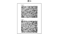
- FIG. 6A and 6B are photographs of flake orientation in a plan view when a voltage is applied between the opposing electrodes 112 and 122 in the light control device 40 (light control cell) actually manufactured.
- FIG. 6A shows a case where a DC voltage of 2 V is applied between the electrodes 112 and 122
- FIG. 6B shows a state between the electrodes 112 and 122. , 60 Hz, 5 V when an AC voltage is applied.
- the light control apparatus 40 was produced according to the manufacturing method mentioned above.
- the flakes are generally oriented in a direction parallel to the substrates 110 and 120. For this reason, the near-infrared light which entered into the light control cell is reflected by the incident side of light.
- the substrate 110 is disposed on the outdoor side, and the substrate 120 is disposed on the indoor side. Therefore, in the near-infrared light reflection state shown in FIGS. 5A and 6A, near-infrared light incident from the outside is flakes of the shape anisotropic member 132 in the light control device 40. The light is regularly reflected on the surface and efficiently reflected on the incident side.
- near-infrared light transmission state shown in FIGS. 5B and 6B
- near-infrared light incident from the outside is transmitted indoors.
- the near-infrared light transmission state even if the near-infrared light from the outside is incident on the substrate surface (incident side) of the substrate 110 from an oblique direction as shown in FIG. The light is reflected by the flake surface of the anisotropic member 132 and is incident on the indoor-side substrate 120.
- the near-infrared light reflection state and the near-infrared light transmission state are achieved by switching the orientation state of the shape anisotropic member 132 between a state parallel to the substrates 110 and 120 and a state perpendicular to the substrates 110 and 120.
- the light control device 40 may switch between the near-infrared light reflection state and the near-infrared light transmission state based on a signal from the communication unit 54 or the switch unit 55, or may be set in advance. You may make it switch a near-infrared-light reflective state and a near-infrared-light transmissive state according to a time schedule.
- control unit 52 controls the orientation state of the shape anisotropic member 132 based on the time schedule stored in the storage unit 53. That is, the orientation state of the shape anisotropic member 132 is automatically controlled according to the time schedule stored in the storage unit 53.
- the projected area of the shape anisotropic member 132 onto the pair of substrates 110 and 120 is changed, and the proximity is changed. Controls switching between the reflection state and transmission state of infrared light. This control is executed according to the time schedule.
- the light control device 40 is held in the frame of the basket 20 by being fixed in the recess 25 provided in the built-in part 24 of the basket 20 by the grating channel 31.
- the light control device 40 is disposed to face the window glass 11 so as to overlap the plate surface of the window glass 11 when viewed from a direction perpendicular to the plate surface of the window glass 11.
- the light control device 40 may be attached to the window glass 11 with an adhesive layer 72 (adhesion layer) such as a glue or a UV curable resin, for example.
- the light control device 40 can be attached to the window glass 11 while being slightly warped. For this reason, in this case, there is an advantage that the light control device 40 can be easily attached to the window glass 11 so that bubbles are not bitten.
- the sealing material 142 faces the grating channel 31 as shown in FIG. It is preferable to arrange in the position. Thereby, the light control device 40 can be installed between the pair of substrates 110 and 120 so that the pressure of the grating channel 31 is applied, for example, to a portion where the sealing material 142 having a strong resin sealing material exists. . Furthermore, since the sealing material 142 is not visible from the outside, the light control window 1 with high designability can be formed.
- the light control device 40 is arranged so that the sealing material 142 does not face the grating channel 31 inside the window body unit 10, that is, inside the tub 20, rather than the grating channel 31. Also good.
- the light modulation layer 130 does not exist outside the sealing material 142. For this reason, by arranging the sealing material 142 on the inner side (that is, closer to the center) of the frame of the flange 20 than the grating channel 31, the portion to which the pressure of the grating channel 31 is applied is one of the pair of substrates 110 and 120.
- the light control device 40 can be configured such that only the substrate is formed, or the wiring 71 or the flexible substrate for wiring is arranged.
- Electrodes 112 and 122 ⁇ Modification of electrodes 112 and 122>
- the light control device 40 When the light control device 40 is not intended for display like the near-infrared light control unit, there may be one electrode extraction unit or a plurality of electrode extraction units with respect to one transparent electrode. May be.
- the assembly process of the light control device 40 can be simplified and the routing of the wiring 71 can be simplified.
- the wiring 71 when a plurality of electrode extraction portions are provided, for example, when the light modulation layer 130 (light control layer) of the light control device 40 has a resistance component (that is, when current flows), the wiring 71 Thus, the operation of the light modulation layer 130 at a location far from the connection portion of the first and second connection portions can be ensured, and a partial response speed delay can be prevented.
- a voltage drop occurs toward a portion far from the terminal of each wiring 71 extended from the power supply unit 51 on the electrode surface. For this reason, even if a predetermined voltage is applied from the power supply unit 51, the portions of the electrodes 112 and 122 far from the power supply unit 51 (that is, portions far from the terminals of the wires 71) are driven by the light control device 40. The necessary voltage is not applied, and the flakes are difficult to operate.
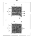
- 7A and 7B are diagrams showing an example in which an electrode for applying a voltage to the light modulation layer 130 is divided and formed.
- 7A and 7B as an example, the case where the electrode 122 is divided is shown as an example.
- each electrode 122a may be routed and integrated into the electrode extraction portion 123.
- the routing part 122b of each electrode 122a is from a part where the light modulation layer 130 operates, for example, below the sealing material 142 (that is, a part overlapping the sealing material 142) or outside the sealing material 142.
- a lead-out portion 122b is provided for each of the divided electrodes 122a.
- the electrode extraction part 123 may be provided without being routed, and the wiring 71 may be directly connected to each electrode extraction part 123.
- the electrode 112 facing the electrode 122 may be divided in the same manner as the electrode 122 or may not be divided. Needless to say, only the electrode 112 may be divided.
- Window body> the case where the window main body which is a translucent member was the window glass 11 was mentioned as an example, and was demonstrated.
- the present embodiment is not limited to this, and instead of the window glass 11 made of a glass member (glass plate) as a window main body, a translucent plate material made of a translucent resin such as a transparent resin, etc. May be used.
- the light control system concerning this embodiment was the light control window 1
- the light control system may be, for example, a screen, a door, a showcase or the like having a light control function.
- the light control device 40 is a near-infrared light control device
- the wavelength of light that is adjusted by the light control device 40 is not particularly limited.
- the shape anisotropic member 132 can be changed as appropriate according to the application.
- permeability of near-infrared light is changed by switching the light control state of the light control apparatus 40 with a near-infrared-light reflection state and a near-infrared-light transmission state is mentioned as an example.
- the present embodiment is not limited to this.
- the light control state of the light control device 40 can be changed to the light transmission state, or the light scattering state. It is also possible to have a light reflection state due to mirror reflection, a light reflection (mirror surface) state due to mirror reflection, or a light absorption (black) state.
- the light control device 40 may be a display device.
- At least a part of the drive device 50 that drives the light control device 40 is a support portion (a built-in portion) of a support member that supports the light-transmissive member in the light control system.
- the dimming system is a light control window and external light (natural light) is used as a light source
- the dimming system is an article used indoors, such as a glass screen
- the dimming system may use an indoor light as the light source, and the dimming system uses an artificial light source as the light source. It does not matter as a configuration provided.
- the dimming window 1 may be a sliding window, or a left / right opening window, a double door opening window, a raising / lowering window, a snapping window, a rotating window, an outside turn.
- Other windows such as a window and an interior fall window, may be used.
- the present embodiment a case where the light control system according to the present embodiment is a light control window will be described as an example.
- the present embodiment is not limited to this.
- FIG. 8 is a cross-sectional view illustrating a schematic configuration of a main part of the light control window 1 according to the present embodiment.
- FIG. 9 is sectional drawing which shows schematic structure of the principal part of the window main body unit 10 in the light control window 1 concerning this embodiment.
- the light control window 1 according to the present embodiment has the same configuration as the light control window 1 according to the first embodiment, except for the following points.
- the light control window 1 concerning Embodiment 1 is equipped with the single plate glass (window glass 11) as a translucent member (window main body).
- the light control window 1 concerning this embodiment is a double window, and as shown to FIG. 8 and FIG. 9, as a window main body (translucent member), the multilayer which consists of window glass 11 * 12 Has glass.
- the window glasses 11 and 12 have the same outer shape. When viewed from a direction perpendicular to the plate surfaces of the window glasses 11 and 12, the window glasses 11 and 12 have a window on the plate surface of the window glass 11 (first translucent member) with the light control device 40 interposed therebetween.
- the glass 12 (second translucent member) is disposed to face each other with a spacer 32 therebetween so that the plate surfaces of the glass 12 (second translucent member) overlap.
- the light control window 1 (light control system) concerning this embodiment is the window glass 11 * 12 (window main body, a translucent member), the eaves 20 (support body), the grating channel 31, the spacer 32, and the light control.
- the apparatus 40, the drive device 50 (refer FIG. 2), and the communication apparatus 61 (refer FIG. 2) are provided.
- window glasses 11 and 12 may be formed of the same material or different materials. Further, the thicknesses of the window glasses 11 and 12 may be the same or different from each other.
- the window glass 11 is disposed facing the outdoors, and the window glass 12 is disposed facing the indoors.
- the light control device 40 is provided for the window main body made of the multi-layer glass as in the present embodiment, the light control device 40 is broken between the two window glasses 11 and 12 so that the light control device 40 is damaged. Can be avoided.
- the light control device 40 may be attached to the window glass 11 with an adhesive layer 72 (adhesion layer) such as a glue or a UV curable resin, as shown in FIG. Good.
- an adhesive layer 72 adhesive layer
- glue glue or a UV curable resin
- the light control device 40 is a near-infrared light control unit
- the near-infrared light from the sun is transmitted to the window glass 11 and the window glass 12 by attaching the light control device 40 to the window glass 11 on the outdoor side.
- Near infrared light can be blocked before reaching the space between the two. Therefore, in this case, a high heat shielding effect can be obtained in summer.
- spacer 32 for example, an existing spacer such as an aluminum spacer containing a desiccant or a resin spacer can be used.
- the light control device 40 is attached to the surface of the outdoor window glass 11 facing the window glass 12, so that the spacer 32 is interposed between the light control device 40 and the window glass 12. Has been placed.
- the grating channel 31 is wound around the window glasses 11 and 12 so as to sandwich the window glass 11 and the window glass 12 to which the light control device 40 is attached. As shown in FIG. 8, the window glasses 11, 12 and the light control device 40 are fixed in the recess 25 provided in the built-in portion 24 of the basket 20 by the grating channel 31, so that Is retained.
- the window glasses 11 and 12 and the light control device 40 are integrated by a spacer 32 and a grating channel 31.
- the window body unit 10 includes window glasses 11 and 12, a light control device 40, a spacer 32, and a grating channel 31, and these window glasses 11 and 12, the light control device 40, the spacer 32, and the grating channel.
- Reference numeral 31 denotes a single window body unit 10 that is integrally assembled to the flange 20.
- the sealing material 142 includes the grating. It is preferable that the channel 31 and the spacer 32 be disposed at positions facing each other. Thereby, the light control device 40 is installed between the pair of substrates 110 and 120 so that the pressure of the grating channel 31 and the spacer 32 is applied to a portion where, for example, a strong resin sealing material exists as the sealing material 142. be able to. Furthermore, since the sealing material 142 is not visible from the outside, the light control window 1 with high designability can be formed.
- the sealing material 142 has the grating channel 31 and the spacer 32 on the inner side of the window body unit 10 than the grating channel 31 and the spacer 32, that is, inside the frame of the flange 20. You may arrange
- the part to which the pressure of the grating channel 31 and the spacer 32 is applied is configured such that only one of the pair of substrates 110 and 120 is formed, or the wiring 71 or the wiring flexible substrate is arranged.
- the light control device 40 can be formed.
- the light control window 1 has at least four interfaces between a solid such as glass and a gas such as air. It is formed. At these interfaces, since interface reflection occurs, the transmittance of light including visible light is lowered. For this reason, it is preferable that an antireflection film is formed on these interfaces. For example, as shown in FIG. 9, when the light control device 40 is attached to the window glass 11, it is preferable to form an antireflection film 81 on the surface of the light control device 40 facing the window glass 12.
- the antireflection film 81 may be provided on at least one of the interfaces with the air in the window glasses 11 and 12, and the antireflection film 81 is provided on all of the four interfaces. It doesn't matter.
- an existing antireflection film such as an AR (Anti Reflective) film, an LR (Low Reflective) film, or a moth-eye film can be used.
- the present embodiment a case where the light control system according to the present embodiment is a light control window will be described as an example.
- the present embodiment is not limited to this.
- FIG. 10 is a cross-sectional view illustrating a schematic configuration of a main part of the window main body unit 10 in the light control window 1 according to the present embodiment.
- the light control window 1 according to the present embodiment has the same configuration as the light control window 1 according to the first and second embodiments, except for the following points.
- the light control window 1 includes a multi-layer glass composed of window glasses 11 and 12 as a window body (translucent member) as in the second embodiment.
- the light control device 40 is provided between the window glass 11 and the window glass 12 so as to be separated from the window glasses 11 and 12.
- the light control device 40 is installed without using an adhesive layer (adhesive layer), for example, by holding the both sides with spacers 32 and 32 instead of the central glass of the triple glass.
- an adhesive layer adhesive layer
- spacer 32 an existing spacer can be used as in the second embodiment.
- the light control device 40 can be prevented from being damaged by providing the light control device 40 between the two window glasses 11 and 12.
- the grating channel 31 is wound around the window glasses 11 and 12 so as to sandwich the window glass 11 and the window glass 12 between which the light control device 40 is disposed.
- the window glasses 11 and 12 and the light control device 40 are integrated by spacers 32 and 32 and the grating channel 31.
- the window body unit 10 includes window glasses 11 and 12, a light control device 40, spacers 32 and 32, and a grating channel 31, and these window glasses 11 and 12, light control device 40, and spacers 32 and 32.
- the grating channel 31 are integrally assembled to the basket 20 as one window body unit 10.
- the sealing material 142 includes the grating.
- the grating channel 31 and the spacers 32 and 32 are disposed at positions opposite to the channel 31 and the spacers 32 and 32, or the inner side of the window body unit 10 than the grating channel 31 and the spacers 32 and 32, that is, inside the frame of the flange 20. It is preferable that the spacers 32 and 32 are disposed so as not to face each other.
- the sealing material 142 is disposed inside the frame of the flange 20 with respect to the grating channel 31 and the spacers 32 and 32 is illustrated as an example, but as illustrated in FIGS. 3 and 9 In addition, the sealing material 142 may be disposed at a position facing the grating channel 31 or the spacer 32.
- the sealing material 142 is arranged inside the frame of the flange 20 with respect to the grating channel 31 and the spacers 32 and 32, as shown in FIG. Only one of the substrates 110 and 120 may be formed. Further, in this case, the light control device 40 can be formed so that the wiring 71 or the wiring flexible substrate is arranged in the portion to which the pressure of the grating channel 31 and the spacers 32 and 32 is applied.
- the light control window 1 having a triple glass configuration in which the light control device 40 is disposed at the center of the two window glasses 11 and 12 at least a solid such as glass and a gas such as air are used. 6 interfaces are formed. At these interfaces, since interface reflection occurs, the transmittance of light including visible light is lowered. For this reason, as shown in FIG. 10, when the light control device 40 is arranged at the center of the two window glasses 11 and 12, for example, an antireflection film 81 is formed on both surfaces of the light control device 40. Is preferred.
- the antireflection film 81 may be provided on at least one of the interfaces with the air in the window glasses 11 and 12, and the antireflection film 81 is provided on all of the six interfaces. It doesn't matter.
- the present embodiment a case where the light control system according to the present embodiment is a light control window will be described as an example.
- the present embodiment is not limited to this.
- FIG. 11 is a front view illustrating a schematic configuration of a main part of the light control window 1 according to the present embodiment.
- 12 (a) and 12 (b) are cross-sectional views showing a schematic configuration of the main part of the light control window 1 according to the present embodiment.
- FIG. FIG. 12B shows a state when the light control window 1 is locked.
- the light control window 1 according to the present embodiment has the same configuration as the light control window 1 according to the first to third embodiments, except for the following points.
- the light control window 1 is a sliding window that opens and closes by sliding in the horizontal direction, and includes a first light control window 2 and a second light control window 3 that are slidably provided within the window frame 7. I have.
- the first dimming window 2 is a front side shoji provided on the front (near) side when viewed from the operator
- the second dimming window 3 is the back surface of the first dimming window 2 when viewed from the operator ( It is a back side shoji provided on the back side.
- the first light control window 2 includes a window main body unit 10A and a flange 20A (first rod) that supports the window main body unit 10A. Moreover, the 2nd light control window 3 is provided with the window main body unit 10B and the collar 20B (2nd collar) which supports the window main body unit 10B.
- the window body units 10A and 10B have the same configuration as the window body unit 10 in the first to third embodiments.
- the scissors 20A and 20B have the same configuration as that of the scissors 20 in the first to third embodiments, except that an opening / closing part 27 is provided only on one vertical reed 23 of the reed 20A. ing.
- the light control window 1 (light control system) according to the present embodiment includes the window main body units 10A and 10B, the flanges 20A and 20B (support), the drive device 50, and the communication device 61.
- the window main body unit 10A includes at least one window main body (first window main body) made of a light transmissive material such as glass or transparent resin as a light transmissive member, and is opposed to the window main body as a light control device.
- the light control device 40 (the 1st light control part, the 1st light control device) arrange
- the window body unit 10B includes at least one window body (second window body) made of a light transmissive material such as glass or transparent resin as a light transmissive member, and the window body as a light control device. Is provided with a light control device 40 (a second light control unit, a second light control device) disposed opposite to each other.
- a light control device 40 a second light control unit, a second light control device
- the first dimming window 2 and the second dimming window 3 are formed by opening the dimming window 1 which is a sliding window, so that the window main body unit 10A in the frame of the flange 20A in the first dimming window 2
- the dimming window 1 in the first dimming window 2 which is a summing window.
- the vertical rod 23 located inside the window and the vertical rod 23 located inside the light adjustment window 1 in the second light adjustment window 3, which is a summoning rice cake, are overlapped in front view.
- the front view shows the time when viewed from the direction perpendicular to the plate surface of the window body (for example, the window glass 11) in the window body units 10A and 10B.
- each said vertical fence 23 which is a summoning bowl contacts each other.
- the first dimming window 2 is located on the indoor side when the first dimming window 2 and the second dimming window 3 are overlapped, and the second dimming window 3 is the first dimming window 2 and the second dimming window 3. It arrange
- the first dimming window 2 can be said to be an indoor shoji, and the second dimming window 3 can be paraphrased to be an outdoor shoji.
- the vertical fences 23 located on the indoor side, which are on the operator side.
- An opening / closing part 27 is provided on a part of the surface.
- the opening / closing part 27 is provided only in one first dimming window 2 located on the indoor side when the sliding window is closed.
- the driving device 50 is provided in the accommodating portion 26 provided in the first light control window 2 covered with the opening / closing portion 27.
- the first dimming window 2 is provided with a connection portion to the second dimming window 3 and wiring connected to the connection portion.
- the second dimming window 3 is provided with a connection portion to the first dimming window 2 and a wiring connected to the connection portion.
- the connecting portion in the first light control window 2 is provided on the surface facing the second light control window 3 in the vertical wall 23 which is a summoning bowl in the first light control window 2.
- connection part in the 2nd light control window 3 is provided in the opposing surface with the 1st light control window 2 in the vertical wall 23 which is the summon candy in the 2nd light control window 3.
- the connecting portion of the first dimming window 2 and the first dimming window 2 are connected.
- the contact part of the 2nd light control window 3 contacts, and the connection part of the 1st light control window 2 and the connection part of the 2nd light control window 3 are electrically connected.
- the connection part of the first dimming window 2 and the connection part of the second dimming window 3 are in contact with each other. By doing so, each is electrically connected to the power supply unit 51 via the connection unit.
- the switch unit 55 and the like provided in the first dimming window 2 with the sliding window closed the dimming in the window main body unit 10A of the first dimming window 2 is performed.
- the light device 40 and the light control device 40 in the window main body unit 10B of the second light control window 3 can be operated simultaneously or individually.
- connection part in the 1st light control window 2 and the connection part in the 2nd light control window 3 are ensured, or it contacts the connection part provided in the 1st light control window 2 in which the drive device 50 was provided.
- the connection of the connection portion is synchronized with the opening / closing (that is, unlocking or locking) operation of the lock provided on the difference window, etc. An operation different from the opening / closing operation may be required.
- connection portions may be formed so that the connection portion in the optical window 3 is electrically connected or disconnected.
- the crescent rotation shaft 5 of the crescent lock 4 is brought into contact with the connecting portion 221 of the first light control window 2 when the crescent lock 4 is rotated.
- a contact member 6 is provided.
- connection part 221 is disposed opposite to the connection part 211 in the second light control window 3.
- the connection parts 211 and 221 are each formed of a conductive member such as metal.
- the connecting portion 211 is provided with a plurality of wirings 212 for connecting the connecting portion 211 and the light control device 40 in the window main body unit 10B in place of the wiring 71.
- the connection part 221 is provided with a plurality of wirings 225 that connect the connection part 221 and the light control device 40 in the window main body unit 10 ⁇ / b> A.
- the connecting portion 221 is provided with a plurality of wirings 225 for connecting the connecting portion 221 and the power supply unit 51 separately from the wiring 225 for connecting the connecting portion 221 and the light control device 40 in the window body unit 10A. It has been.
- the connecting portion 221 is disposed between the pair of spring support portions 222 and 223.
- An opening 222 a is provided in the spring support portion 222 facing the connection portion 211.
- the connecting portion 221 is smaller than the opening 222a, and the connecting portion 221 is provided with a plate-like fringe portion 226 having a larger diameter than the opening 222a as a stopper.
- Springs 224 are provided between the fringe portion 226 and the spring support portion 222 and between the fringe portion 226 and the spring support portion 223, respectively.
- connection part 211 and the connection part 221 are in a non-contact state as shown in FIG.
- the abutting member 6 provided on the crescent rotation shaft 5 abuts on the connecting portion 221.
- the connection part 221 is pushed by the contact member 6, the spring 224 provided between the spring support part 222 and the fringe part 226 contracts, so that the connection part 221 synchronizes with the operation of rotating the crescent lock 4. Then, it is pushed out from the opening 222a toward the vertical rod 23 of the second dimming window 3 facing the opening 222a. Thereby, the connection part 211 and the connection part 221 contact.
- connection portion 221 that has been pushed by the abutting member 6 is retracted by the force with which the spring 224 returns to its original state by releasing the bias of the spring 224. Thereby, the connection part 211 and the connection part 221 are separated, and the electrical connection between the connection part 211 and the connection part 221 is released.
- connection part 211 and the connection part 221 have been described by taking as an example the case where the connection part 211 and the connection part 221 are provided on the mutually facing surfaces of the vertical shaft 23 that overlap each other when the sliding window is closed.
- the embodiment is not limited to this.
- These connecting portions 211 and 221 may be provided on the crescent portion and the receiving portion of the crescent lock 4 provided on the vertical shaft 23 that overlaps each other when the sliding window is closed.
- the dimming window 1 is a sliding window
- the movable dimmers having a summing bowl that contacts each other when the dimming window 1 is closed.
- the first dimming window 2 and the second dimming window 3 may be raising and lowering windows that slide in the vertical direction. Also in this case, the same effect as that of the present embodiment can be obtained only by changing the sliding direction.
- the light control window 1 has the 1st light control window 2 and the 2nd light control window 3, and in the window frame 7, the 1st light control window 2 and the 2nd light control window 3 and
- the dimming window 1 may include, for example, a third dimming window (not shown) in addition to the first dimming window 2 and the second dimming window 3, and is arranged in the window frame 7.
- the number of light windows may be three or more.
- the case where the opening-and-closing part 27 and the accommodating part 26 are provided only in one ridge 20A of the position of the ridge 20A in the 1st light control window 2 and the ridge 20B in the 2nd light control window 3 is taken as an example.
- the lids 20A and 20B may be provided with an opening / closing part 27 and a housing part 26, respectively, and the light control devices 40 supported by the respective bowls 20A and 20B in the housing part 26 of the respective bowls 20A and 20B. At least a part of the driving device 50 that drives the motor may be provided.
- the opening / closing portion 27 and the accommodating portion 26 of each of the baskets 20A and 20B are provided in portions that do not overlap each other when the light control window 1 is closed. Thereby, for example, the same effect as in the first embodiment can be obtained.
- the light control system (light control window 1) concerning the aspect 1 of this invention is opposed to the translucent member (a window main body, a single plate glass, a multi-layer glass, the window glass 11, the window glass 12), and the said translucent member.
- a light control device 40 that is arranged and changes the light transmittance by applying a voltage
- a drive device 50 that drives the light control device 40
- a built-in portion that incorporates the light-transmissive member and the light control device 40
- a housing portion 26 that houses at least a part of the drive device 50
- an opening / closing portion 27 that covers the housing portion 26 in an openable and closable manner. And are provided.
- the light control system according to aspect 2 of the present invention is the light control system according to aspect 1, in which the drive device 50 supplies the light control device 40 with power for driving the light control device 40 and the power supply unit 51.
- a control unit 52 that controls driving of the light control device 40, and at least the power supply unit 51 and the control unit 52 may be housed in the housing unit 26.
- a power source 51 and a controller 52 are required.
- components that have a high need for replacement or repair be disposed in the accommodating portion 26. According to the above configuration, when the power supply unit 51 or the control unit 52 becomes inoperable due to a life or failure, the battery or the power supply unit 51 or the control unit 52 can be replaced without disassembling the bag 20. Can be repaired.
- the drive device 50 includes a switch unit 55 that switches the transmittance of the light control device 40, and a communication unit 54 that is connected to the control unit 52. , And at least one of the switch unit 55 and the communication unit 54 may be housed in the housing unit 26.
- the driving device 50 includes the switch unit 55 and the communication unit 54, it is possible to replace and repair the parts of the switch unit 55 and the communication unit 54 without disassembling the bag 20.
- the communication unit 54 installs the light control system from a server that distributes climate information (weather and temperature) via a communication network.
- the control unit 52 may control the driving of the light control device 40 so as to obtain a target solar heat acquisition rate according to the climate information. .
- the weather information associated with the address where the light control system is installed can be reflected in the control of the light control device 40.
- the communication unit 54 may be connected to be communicable with the HEMS controller.
- the power consumption of the said light control system can be managed by HEMS which manages the power consumption in each household appliance in each door.
- the light control device 40 is fixed to the surface of the translucent member by an adhesive layer (adhesive layer 72). May be.
- the interface reflection occurs at the interface between a solid such as glass and a gas such as air, the transmittance of light including visible light is low.
- the interface mentioned above does not exist between the said light modulation apparatus 40 and the said translucent member, and it can suppress the fall of the transmittance
- the said light control apparatus 40 can be hold
- the light control system according to aspect 7 of the present invention is the light control system according to any one of the above aspects 1 to 5, wherein the light control device 40 includes a pair of substrates 110 and 120 bonded together by a sealing material 142, and the light transmitting member.
- a gasket (grating channel 31) is provided between the support member and the support, and the sealing material 142 may be disposed at a position facing the gasket.
- the light control device 40 can be installed so that the pressure of the gasket is applied to a portion where the sealing material 142 exists between the pair of substrates 110 and 120. Moreover, according to said structure, since the sealing material 142 is not visible from the outside, the light control system with high designability can be provided.
- the light control system according to aspect 8 of the present invention is the light transmission system according to any one of the above aspects 1 to 5, wherein the translucent member (window body, multi-layer glass) is provided so as to face each other.
- a member (window glass 11) and a second light transmissive member (window glass 12), and the light control device 40 is provided between the first light transmissive member and the second light transmissive member. It may be arranged.
- the light control device 40 can be prevented from being damaged by disposing the light control device 40 between the first light transmitting member and the second light transmitting member.
- the light control system according to the ninth aspect of the present invention is the light control system according to the eighth aspect, wherein the light control device 40 includes the first light transmissive member and the second light transmissive property by an adhesive layer (adhesive layer 72). You may fix to the surface of one translucent member among members.
- the said light control system is a light control window installed in the position which separates indoors and the outdoors, and the said light control apparatus 40 is used as a near-infrared light control part, from the sun
- the near infrared light can be blocked before the near infrared light reaches the translucent member on the indoor side. Therefore, in this case, a high heat shielding effect can be obtained in summer.
- the light control system according to aspect 10 of the present invention is the light control system according to aspect 9, wherein the light control device 40 includes the first light transmission member between the first light transmission member and the second light transmission member.
- the optical member and the second translucent member may be provided separately from each other.
- the light control system of the triple glass structure which has arrange
- the first light transmissive member and the second light transmissive member are disposed to face each other with a spacer 32 interposed therebetween.
- the light control device 40 includes a pair of substrates 110 and 120 bonded together by a sealant 142, and is provided between the first light transmissive member and the second light transmissive member and the support. Is provided with a gasket (grating channel 31), and the sealing material 142 may be disposed at a position facing the gasket and the spacer 32.
- the light control device 40 can be installed so that the pressure of the gasket and the spacer 32 is applied to a portion where the sealing material 142 exists between the pair of substrates 110 and 120. Moreover, according to said structure, since the sealing material 142 is not visible from the outside, the light control system with high designability can be provided.
- the first light transmissive member and the second light transmissive member are disposed to face each other with a spacer 32 interposed therebetween.
- the light control device 40 includes a pair of substrates 110 and 120 bonded together by a sealant 142, and is provided between the first light transmissive member and the second light transmissive member and the support. Is provided with a gasket (grating channel 31), one of the pair of substrates 110 and 120 is larger than the other substrate, and the sealing material 142 faces the gasket and the spacer 32. However, only the one substrate may face the gasket and the spacer 32.
- the portion to which the pressure of the gasket is applied can be configured such that only one of the pair of substrates 110 and 120 is formed. Therefore, according to said structure, it can avoid that the pressure of a gasket is applied to the inside part of sealing materials 142, such as a light modulation layer, in a pair of board
- the light control system according to aspect 13 of the present invention is the light control system according to any one of the above aspects 1 to 12, wherein the light control system is the light control window 1, and the translucent member is a window body (window glass 11, window glass 12). ) And the support may be a ridge 20.
- the light control window 1 which can perform the repair of a drive device 50, battery replacement, parts replacement, etc., without disassembling the incorporating part 24 of a window main body as a light control system. it can.
- the dimming system according to the fourteenth aspect of the present invention is the movable light window according to the thirteenth aspect, wherein the dimming window 1 is a movable window having summing rods (vertical rods 23) that come into contact with each other when the dimming window 1 is closed.
- the ridge 20 includes a frame-shaped first ridge ( ⁇ 20A) and a second ridge ( ⁇ 20B), and the first and second ridges are slidably provided in the window frame 7, respectively. Each of which has the summoning bowl, and the window body is supported by the first window (the first window body (the window body (single plate glass, multilayer glass) of the window body unit 10A), the window glass).
- the light control device 40 includes a first light control device (window book) disposed to face the first window body.
- the opening / closing part 27 may be provided on a part of the surface of one of the summoning bowls on the side opposite to the contact surface with the other summoning bowl.
- said structure has a light control function provided slidably within the window frame 7, such as a sliding window, a raising / lowering window, etc. as a light control system, and the built-in part 24 of a window main body is decomposed
- the summing rods in the first rod and the second rod are provided with connecting portions 211 and 221 connected to each other.
- the connecting portion provided on the one summoning rod provided on the summoning rod provided with the opening / closing portion 27 is connected to the driving device 50, and when the dimming window 1 is closed,
- the first light control device and the second light control device may be driven by the driving device 50 by electrically connecting the connecting portions 211 and 221.
- each said connection part 211 * 221 is electrically connected,
- the said drive device 50 the said 1st light control apparatus and the said 2nd light control are carried out.
- the device can be driven.
- the light control system according to the sixteenth aspect of the present invention is the light control system according to the fifteenth aspect, wherein a lock (crescent lock 4) is provided on the summoning bowl, and the connecting portion 211 is accompanied by a locking operation or an unlocking operation of the lock. -221 may contact or space apart.
- connection portions 211 and 221 it is possible to ensure the connection between the connection portions 211 and 221 or to avoid a leakage or electric shock when contacting the connection portion connected to the driving device 50.
- the light control system of the present invention can be suitably used for a movable window in which the window itself is movable, such as a sliding window or a raising / lowering window.
- the light control system of the present invention facilitates a light control device and a drive device that drives the light control device for a building member that needs to be replaced independently of a building, such as a sash. Can be maintained.
Landscapes
- Engineering & Computer Science (AREA)
- Structural Engineering (AREA)
- Civil Engineering (AREA)
- Architecture (AREA)
- Electrochromic Elements, Electrophoresis, Or Variable Reflection Or Absorption Elements (AREA)
- Liquid Crystal (AREA)
- Wing Frames And Configurations (AREA)
Abstract
Un système de gradation est, par exemple, une fenêtre de gradation (1) qui comprend un verre à vitre (11), un dispositif de gradation (40), un dispositif d'entraînement (50), et un cadre (20) ayant une partie d'insertion (24) dans laquelle sont insérés le verre à vitre (11) et le dispositif d'entraînement (50). Une partie du cadre (20) est pourvue d'une partie de logement (26) qui contient au moins une partie du dispositif d'entraînement (50), et d'une unité d'ouverture et de fermeture (27) qui recouvre la partie de logement (26) de sorte que celle-ci peut être ouverte et fermée librement.
Priority Applications (3)
| Application Number | Priority Date | Filing Date | Title |
|---|---|---|---|
| CN201680034416.2A CN107735543B (zh) | 2015-06-17 | 2016-05-06 | 调光系统 |
| US15/736,480 US10508487B2 (en) | 2015-06-17 | 2016-05-06 | Dimming system |
| JP2017524716A JP6517338B2 (ja) | 2015-06-17 | 2016-05-06 | 調光システム |
Applications Claiming Priority (2)
| Application Number | Priority Date | Filing Date | Title |
|---|---|---|---|
| JP2015122366 | 2015-06-17 | ||
| JP2015-122366 | 2015-06-17 |
Publications (1)
| Publication Number | Publication Date |
|---|---|
| WO2016203860A1 true WO2016203860A1 (fr) | 2016-12-22 |
Family
ID=57545183
Family Applications (1)
| Application Number | Title | Priority Date | Filing Date |
|---|---|---|---|
| PCT/JP2016/063636 WO2016203860A1 (fr) | 2015-06-17 | 2016-05-06 | Système de gradation |
Country Status (4)
| Country | Link |
|---|---|
| US (1) | US10508487B2 (fr) |
| JP (1) | JP6517338B2 (fr) |
| CN (1) | CN107735543B (fr) |
| WO (1) | WO2016203860A1 (fr) |
Cited By (3)
| Publication number | Priority date | Publication date | Assignee | Title |
|---|---|---|---|---|
| WO2019039573A1 (fr) * | 2017-08-24 | 2019-02-28 | 大日本印刷株式会社 | Cellule de modulation de lumière, dispositif de modulation de lumière, véhicule, procédé de fabrication de cellule de modulation de lumière et procédé de fabrication de dispositif de modulation de lumière |
| JP2021026076A (ja) * | 2019-08-01 | 2021-02-22 | 大日本印刷株式会社 | 調光装置、調光装置用積層体及び調光セル |
| JP2021130953A (ja) * | 2020-02-19 | 2021-09-09 | 凸版印刷株式会社 | 調光装置及び調光制御方法 |
Families Citing this family (3)
| Publication number | Priority date | Publication date | Assignee | Title |
|---|---|---|---|---|
| JP6893262B2 (ja) * | 2019-02-08 | 2021-06-23 | 日東電工株式会社 | スマートウィンドウ制御装置、スマートウィンドウ制御方法及びスマートウィンドウ制御プログラム |
| DE202020103920U1 (de) * | 2020-07-07 | 2021-10-08 | Rehau Ag + Co | Fenster oder Tür sowie dieses bzw. diese umfassende Gebäudewand |
| US11726379B2 (en) * | 2020-11-20 | 2023-08-15 | Wicue Usa Inc. | Liquid crystal assembly |
Citations (5)
| Publication number | Priority date | Publication date | Assignee | Title |
|---|---|---|---|---|
| JPS5424441A (en) * | 1977-07-25 | 1979-02-23 | Fuji Satsushi Kogyo Kk | Revolving window |
| JPH0243393U (fr) * | 1988-09-16 | 1990-03-26 | ||
| JPH08184273A (ja) * | 1994-12-27 | 1996-07-16 | Ohbayashi Corp | 調光ガラス窓 |
| JP2000302486A (ja) * | 1999-04-15 | 2000-10-31 | Nippon Sheet Glass Co Ltd | 日射遮蔽性透光板およびこれを用いた日射遮蔽性複層透光板 |
| WO2015040975A1 (fr) * | 2013-09-20 | 2015-03-26 | シャープ株式会社 | Dispositif de focalisation infrarouge |
Family Cites Families (8)
| Publication number | Priority date | Publication date | Assignee | Title |
|---|---|---|---|---|
| JPH0524441A (ja) | 1991-07-19 | 1993-02-02 | Komatsu Forklift Co Ltd | 産業車両の油圧回路 |
| JPH07293146A (ja) | 1994-04-28 | 1995-11-07 | Mitsubishi Chem Corp | ブラインド |
| JPH11228185A (ja) | 1998-02-06 | 1999-08-24 | Nippon Sheet Glass Co Ltd | 日射遮蔽性透光板およびこれを用いた日射遮蔽性複層透光板 |
| US6592996B1 (en) * | 1998-02-06 | 2003-07-15 | Nippon Sheet Glass Co., Ltd. | Solar-shading light-transmissive panel and solar-shading multi-layer light-transmissive panel using same |
| JP3927112B2 (ja) | 2002-10-31 | 2007-06-06 | 株式会社フジテレビジョン | 調光ガラス制御システム |
| TW201116916A (en) * | 2009-11-02 | 2011-05-16 | Univ Nat Taiwan | Liquid crystal device |
| JP5858444B2 (ja) * | 2011-01-24 | 2016-02-10 | セイジ・エレクトロクロミクス,インコーポレイテッド | エレクトロクロミックデバイス用の制御システム |
| WO2014175190A1 (fr) | 2013-04-24 | 2014-10-30 | 旭硝子株式会社 | Structure de verre multicouche, dispositif d'affichage pour véhicule, et dispositif d'affichage pour unité de réfrigération et de congélation |
-
2016
- 2016-05-06 WO PCT/JP2016/063636 patent/WO2016203860A1/fr active Application Filing
- 2016-05-06 JP JP2017524716A patent/JP6517338B2/ja not_active Expired - Fee Related
- 2016-05-06 US US15/736,480 patent/US10508487B2/en not_active Expired - Fee Related
- 2016-05-06 CN CN201680034416.2A patent/CN107735543B/zh not_active Expired - Fee Related
Patent Citations (5)
| Publication number | Priority date | Publication date | Assignee | Title |
|---|---|---|---|---|
| JPS5424441A (en) * | 1977-07-25 | 1979-02-23 | Fuji Satsushi Kogyo Kk | Revolving window |
| JPH0243393U (fr) * | 1988-09-16 | 1990-03-26 | ||
| JPH08184273A (ja) * | 1994-12-27 | 1996-07-16 | Ohbayashi Corp | 調光ガラス窓 |
| JP2000302486A (ja) * | 1999-04-15 | 2000-10-31 | Nippon Sheet Glass Co Ltd | 日射遮蔽性透光板およびこれを用いた日射遮蔽性複層透光板 |
| WO2015040975A1 (fr) * | 2013-09-20 | 2015-03-26 | シャープ株式会社 | Dispositif de focalisation infrarouge |
Cited By (8)
| Publication number | Priority date | Publication date | Assignee | Title |
|---|---|---|---|---|
| WO2019039573A1 (fr) * | 2017-08-24 | 2019-02-28 | 大日本印刷株式会社 | Cellule de modulation de lumière, dispositif de modulation de lumière, véhicule, procédé de fabrication de cellule de modulation de lumière et procédé de fabrication de dispositif de modulation de lumière |
| JPWO2019039573A1 (ja) * | 2017-08-24 | 2020-09-17 | 大日本印刷株式会社 | 調光セル、調光装置、車両、調光セルの製造方法及び調光装置の製造方法 |
| JP2022164932A (ja) * | 2017-08-24 | 2022-10-27 | 大日本印刷株式会社 | 調光セル、調光装置、車両、調光セルの製造方法及び調光装置の製造方法 |
| JP7169550B2 (ja) | 2017-08-24 | 2022-11-11 | 大日本印刷株式会社 | 調光セル、調光装置、車両、調光セルの製造方法及び調光装置の製造方法 |
| JP2021026076A (ja) * | 2019-08-01 | 2021-02-22 | 大日本印刷株式会社 | 調光装置、調光装置用積層体及び調光セル |
| JP7451898B2 (ja) | 2019-08-01 | 2024-03-19 | 大日本印刷株式会社 | 調光装置、調光装置用積層体及び調光セル |
| JP2021130953A (ja) * | 2020-02-19 | 2021-09-09 | 凸版印刷株式会社 | 調光装置及び調光制御方法 |
| JP7400527B2 (ja) | 2020-02-19 | 2023-12-19 | Toppanホールディングス株式会社 | 調光装置及び調光制御方法 |
Also Published As
| Publication number | Publication date |
|---|---|
| CN107735543B (zh) | 2019-12-24 |
| US20180195340A1 (en) | 2018-07-12 |
| CN107735543A (zh) | 2018-02-23 |
| JP6517338B2 (ja) | 2019-05-22 |
| US10508487B2 (en) | 2019-12-17 |
| JPWO2016203860A1 (ja) | 2018-04-19 |
Similar Documents
| Publication | Publication Date | Title |
|---|---|---|
| WO2016203860A1 (fr) | Système de gradation | |
| Ghosh et al. | Daylight characteristics of a polymer dispersed liquid crystal switchable glazing | |
| US20200355977A1 (en) | Controlling transitions in optically switchable devices | |
| RU2658096C2 (ru) | Управление изменением состояний оптически переключаемых устройств | |
| Barrios et al. | Simulation of the thickness dependence of the optical properties of suspended particle devices | |
| CN110832828A (zh) | 用于建筑物服务的边缘网络 | |
| US11493819B2 (en) | Displays for tintable windows | |
| Papaefthimiou | Chromogenic technologies: Towards the realization of smart electrochromic glazing for energy-saving applications in buildings | |
| Ghosh et al. | Influence of atmospheric clearness on PDLC switchable glazing transmission | |
| Wu et al. | Applications of thermochromic and electrochromic smart windows: Materials to buildings | |
| US11747696B2 (en) | Tandem vision window and media display | |
| US20150073204A1 (en) | Incubator's canopy with sensor dependent variably transparent walls and methods for dimming lights thereof | |
| KR101988532B1 (ko) | 스마트 윈도우 장치 | |
| US7356969B1 (en) | Electronically shaded thin film transparent monochromatic liquid crystal display laminated window shading system | |
| US11892738B2 (en) | Tandem vision window and media display | |
| US20230077008A1 (en) | Tandem vision window and media display | |
| JP2014059338A (ja) | 窓 | |
| US20170371220A1 (en) | Smart window | |
| KR102470079B1 (ko) | 변색 나노 입자, 이를 포함하는 변색 장치 및 이를 포함하는 표시 장치 | |
| US20240085754A1 (en) | Display construct for media projection and wireless charging | |
| US11474385B1 (en) | Electrically controllable privacy glazing with ultralow power consumption comprising a liquid crystal material having a light transmittance that varies in response to application of an electric field | |
| Balakrishnan et al. | Nanostructured electrochromic materials for smart switchable windows | |
| JP2020201339A (ja) | エレクトロクロミック素子およびスマートウィンドウ | |
| US20220035192A1 (en) | Power transfer hinge for privacy glazing structure | |
| CN211692032U (zh) | 一种雾化功能的双层窗 |
Legal Events
| Date | Code | Title | Description |
|---|---|---|---|
| 121 | Ep: the epo has been informed by wipo that ep was designated in this application |
Ref document number: 16811335 Country of ref document: EP Kind code of ref document: A1 |
|
| ENP | Entry into the national phase |
Ref document number: 2017524716 Country of ref document: JP Kind code of ref document: A |
|
| NENP | Non-entry into the national phase |
Ref country code: DE |
|
| 122 | Ep: pct application non-entry in european phase |
Ref document number: 16811335 Country of ref document: EP Kind code of ref document: A1 |