WO2016203595A1 - 金属酸化膜の成膜方法 - Google Patents
金属酸化膜の成膜方法 Download PDFInfo
- Publication number
- WO2016203595A1 WO2016203595A1 PCT/JP2015/067536 JP2015067536W WO2016203595A1 WO 2016203595 A1 WO2016203595 A1 WO 2016203595A1 JP 2015067536 W JP2015067536 W JP 2015067536W WO 2016203595 A1 WO2016203595 A1 WO 2016203595A1
- Authority
- WO
- WIPO (PCT)
- Prior art keywords
- mist
- raw material
- material solution
- oxide film
- metal oxide
- Prior art date
- Legal status (The legal status is an assumption and is not a legal conclusion. Google has not performed a legal analysis and makes no representation as to the accuracy of the status listed.)
- Ceased
Links
Images



Classifications
-
- H—ELECTRICITY
- H10—SEMICONDUCTOR DEVICES; ELECTRIC SOLID-STATE DEVICES NOT OTHERWISE PROVIDED FOR
- H10F—INORGANIC SEMICONDUCTOR DEVICES SENSITIVE TO INFRARED RADIATION, LIGHT, ELECTROMAGNETIC RADIATION OF SHORTER WAVELENGTH OR CORPUSCULAR RADIATION
- H10F71/00—Manufacture or treatment of devices covered by this subclass
- H10F71/129—Passivating
-
- C—CHEMISTRY; METALLURGY
- C23—COATING METALLIC MATERIAL; COATING MATERIAL WITH METALLIC MATERIAL; CHEMICAL SURFACE TREATMENT; DIFFUSION TREATMENT OF METALLIC MATERIAL; COATING BY VACUUM EVAPORATION, BY SPUTTERING, BY ION IMPLANTATION OR BY CHEMICAL VAPOUR DEPOSITION, IN GENERAL; INHIBITING CORROSION OF METALLIC MATERIAL OR INCRUSTATION IN GENERAL
- C23C—COATING METALLIC MATERIAL; COATING MATERIAL WITH METALLIC MATERIAL; SURFACE TREATMENT OF METALLIC MATERIAL BY DIFFUSION INTO THE SURFACE, BY CHEMICAL CONVERSION OR SUBSTITUTION; COATING BY VACUUM EVAPORATION, BY SPUTTERING, BY ION IMPLANTATION OR BY CHEMICAL VAPOUR DEPOSITION, IN GENERAL
- C23C16/00—Chemical coating by decomposition of gaseous compounds, without leaving reaction products of surface material in the coating, i.e. chemical vapour deposition [CVD] processes
- C23C16/22—Chemical coating by decomposition of gaseous compounds, without leaving reaction products of surface material in the coating, i.e. chemical vapour deposition [CVD] processes characterised by the deposition of inorganic material, other than metallic material
- C23C16/30—Deposition of compounds, mixtures or solid solutions, e.g. borides, carbides, nitrides
- C23C16/40—Oxides
-
- C—CHEMISTRY; METALLURGY
- C23—COATING METALLIC MATERIAL; COATING MATERIAL WITH METALLIC MATERIAL; CHEMICAL SURFACE TREATMENT; DIFFUSION TREATMENT OF METALLIC MATERIAL; COATING BY VACUUM EVAPORATION, BY SPUTTERING, BY ION IMPLANTATION OR BY CHEMICAL VAPOUR DEPOSITION, IN GENERAL; INHIBITING CORROSION OF METALLIC MATERIAL OR INCRUSTATION IN GENERAL
- C23C—COATING METALLIC MATERIAL; COATING MATERIAL WITH METALLIC MATERIAL; SURFACE TREATMENT OF METALLIC MATERIAL BY DIFFUSION INTO THE SURFACE, BY CHEMICAL CONVERSION OR SUBSTITUTION; COATING BY VACUUM EVAPORATION, BY SPUTTERING, BY ION IMPLANTATION OR BY CHEMICAL VAPOUR DEPOSITION, IN GENERAL
- C23C16/00—Chemical coating by decomposition of gaseous compounds, without leaving reaction products of surface material in the coating, i.e. chemical vapour deposition [CVD] processes
- C23C16/22—Chemical coating by decomposition of gaseous compounds, without leaving reaction products of surface material in the coating, i.e. chemical vapour deposition [CVD] processes characterised by the deposition of inorganic material, other than metallic material
- C23C16/30—Deposition of compounds, mixtures or solid solutions, e.g. borides, carbides, nitrides
- C23C16/40—Oxides
- C23C16/403—Oxides of aluminium, magnesium or beryllium
-
- C—CHEMISTRY; METALLURGY
- C23—COATING METALLIC MATERIAL; COATING MATERIAL WITH METALLIC MATERIAL; CHEMICAL SURFACE TREATMENT; DIFFUSION TREATMENT OF METALLIC MATERIAL; COATING BY VACUUM EVAPORATION, BY SPUTTERING, BY ION IMPLANTATION OR BY CHEMICAL VAPOUR DEPOSITION, IN GENERAL; INHIBITING CORROSION OF METALLIC MATERIAL OR INCRUSTATION IN GENERAL
- C23C—COATING METALLIC MATERIAL; COATING MATERIAL WITH METALLIC MATERIAL; SURFACE TREATMENT OF METALLIC MATERIAL BY DIFFUSION INTO THE SURFACE, BY CHEMICAL CONVERSION OR SUBSTITUTION; COATING BY VACUUM EVAPORATION, BY SPUTTERING, BY ION IMPLANTATION OR BY CHEMICAL VAPOUR DEPOSITION, IN GENERAL
- C23C16/00—Chemical coating by decomposition of gaseous compounds, without leaving reaction products of surface material in the coating, i.e. chemical vapour deposition [CVD] processes
- C23C16/44—Chemical coating by decomposition of gaseous compounds, without leaving reaction products of surface material in the coating, i.e. chemical vapour deposition [CVD] processes characterised by the method of coating
- C23C16/448—Chemical coating by decomposition of gaseous compounds, without leaving reaction products of surface material in the coating, i.e. chemical vapour deposition [CVD] processes characterised by the method of coating characterised by the method used for generating reactive gas streams, e.g. by evaporation or sublimation of precursor materials
- C23C16/4486—Chemical coating by decomposition of gaseous compounds, without leaving reaction products of surface material in the coating, i.e. chemical vapour deposition [CVD] processes characterised by the method of coating characterised by the method used for generating reactive gas streams, e.g. by evaporation or sublimation of precursor materials by producing an aerosol and subsequent evaporation of the droplets or particles
-
- C—CHEMISTRY; METALLURGY
- C23—COATING METALLIC MATERIAL; COATING MATERIAL WITH METALLIC MATERIAL; CHEMICAL SURFACE TREATMENT; DIFFUSION TREATMENT OF METALLIC MATERIAL; COATING BY VACUUM EVAPORATION, BY SPUTTERING, BY ION IMPLANTATION OR BY CHEMICAL VAPOUR DEPOSITION, IN GENERAL; INHIBITING CORROSION OF METALLIC MATERIAL OR INCRUSTATION IN GENERAL
- C23C—COATING METALLIC MATERIAL; COATING MATERIAL WITH METALLIC MATERIAL; SURFACE TREATMENT OF METALLIC MATERIAL BY DIFFUSION INTO THE SURFACE, BY CHEMICAL CONVERSION OR SUBSTITUTION; COATING BY VACUUM EVAPORATION, BY SPUTTERING, BY ION IMPLANTATION OR BY CHEMICAL VAPOUR DEPOSITION, IN GENERAL
- C23C16/00—Chemical coating by decomposition of gaseous compounds, without leaving reaction products of surface material in the coating, i.e. chemical vapour deposition [CVD] processes
- C23C16/44—Chemical coating by decomposition of gaseous compounds, without leaving reaction products of surface material in the coating, i.e. chemical vapour deposition [CVD] processes characterised by the method of coating
- C23C16/455—Chemical coating by decomposition of gaseous compounds, without leaving reaction products of surface material in the coating, i.e. chemical vapour deposition [CVD] processes characterised by the method of coating characterised by the method used for introducing gases into reaction chamber or for modifying gas flows in reaction chamber
-
- C—CHEMISTRY; METALLURGY
- C23—COATING METALLIC MATERIAL; COATING MATERIAL WITH METALLIC MATERIAL; CHEMICAL SURFACE TREATMENT; DIFFUSION TREATMENT OF METALLIC MATERIAL; COATING BY VACUUM EVAPORATION, BY SPUTTERING, BY ION IMPLANTATION OR BY CHEMICAL VAPOUR DEPOSITION, IN GENERAL; INHIBITING CORROSION OF METALLIC MATERIAL OR INCRUSTATION IN GENERAL
- C23C—COATING METALLIC MATERIAL; COATING MATERIAL WITH METALLIC MATERIAL; SURFACE TREATMENT OF METALLIC MATERIAL BY DIFFUSION INTO THE SURFACE, BY CHEMICAL CONVERSION OR SUBSTITUTION; COATING BY VACUUM EVAPORATION, BY SPUTTERING, BY ION IMPLANTATION OR BY CHEMICAL VAPOUR DEPOSITION, IN GENERAL
- C23C16/00—Chemical coating by decomposition of gaseous compounds, without leaving reaction products of surface material in the coating, i.e. chemical vapour deposition [CVD] processes
- C23C16/44—Chemical coating by decomposition of gaseous compounds, without leaving reaction products of surface material in the coating, i.e. chemical vapour deposition [CVD] processes characterised by the method of coating
- C23C16/455—Chemical coating by decomposition of gaseous compounds, without leaving reaction products of surface material in the coating, i.e. chemical vapour deposition [CVD] processes characterised by the method of coating characterised by the method used for introducing gases into reaction chamber or for modifying gas flows in reaction chamber
- C23C16/45512—Premixing before introduction in the reaction chamber
-
- H—ELECTRICITY
- H10—SEMICONDUCTOR DEVICES; ELECTRIC SOLID-STATE DEVICES NOT OTHERWISE PROVIDED FOR
- H10F—INORGANIC SEMICONDUCTOR DEVICES SENSITIVE TO INFRARED RADIATION, LIGHT, ELECTROMAGNETIC RADIATION OF SHORTER WAVELENGTH OR CORPUSCULAR RADIATION
- H10F77/00—Constructional details of devices covered by this subclass
- H10F77/30—Coatings
- H10F77/306—Coatings for devices having potential barriers
- H10F77/311—Coatings for devices having potential barriers for photovoltaic cells
Definitions
- the present invention relates to a metal oxide film forming method for forming a metal oxide film on a substrate using a mist method.
- a metal oxide film is formed on a substrate.
- a metal oxide film of an open-air solution system such as a spray method, a sol-gel method, a mist CVD (Chemical Vapor Deposition) method or the like is formed. There is a way.
- the raw material solution when the target metal oxide film is formed, the raw material solution is one kind. Although it is possible to prepare the raw material solution in advance, at the time of forming the metal oxide film, one kind of prepared raw material solution is used.
- the conventional method for forming a metal oxide film using non-vacuum film formation technology uses a prepared raw material solution at the time of film formation, so that the metal oxide film is formed using the raw material solution.
- the reaction energy required for this is uniquely determined.
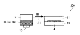
- FIG. 7 is an explanatory diagram showing a schematic configuration of a conventional film forming apparatus 200 using the first method disclosed in Patent Document 1.
- FIG. 7 is an explanatory diagram showing a schematic configuration of a conventional film forming apparatus 200 using the first method disclosed in Patent Document 1.
- the raw material solution 18 solution containing zinc
- the reaction support solution 24 ammonia liquid
- the mist generator 16 supplies the raw material solution 18 and the reaction support solution.
- the mixed solution 34 of 24 is made mist, and mixed mist M4 which is the mixed solution 34 made into mist is obtained.
- the mixed mist M4 is supplied toward the back surface (upper surface) of the P-type silicon substrate 4 in the reaction vessel 11 through the path L11, and the back surface passivation film 5 (aluminum oxide) is formed on the back surface of the P-type silicon substrate 4. Film) is formed.
- the raw material solution 18 and the reaction support solution 24 containing a reaction support agent are the same.
- Mixing is performed in an atomizer (solution container 15 and mist generator 16) to obtain a mixed mist M4, and the mixed mist M4 is supplied toward the back surface (one main surface) of the P-type silicon substrate 4 in the reaction container 11. By doing so, the reaction energy is reduced.
- the reaction support gas is separately supplied to the reaction vessel, and the atmosphere at the time of forming the metal oxide film is adjusted, whereby the raw material misted in the reaction vessel
- the reaction energy is reduced when a metal oxide film is formed by a solution, and the quality of the metal oxide film is improved.
- the first method described above is mixed in the same atomizer to obtain a mixed mist, it is placed in an environment where the raw material solution 18 and the reaction support solution 24 always react (in the atomizer). Will be. Therefore, as the reaction time between the surface electrode 1 and the reaction support solution 24 becomes longer, the mixed mist M4 deteriorates from a desired property, so that a metal oxide film with good film quality cannot be formed. There was a point. For example, destabilization of the mixed mist M4 as a raw material and generation of reactants unnecessary for forming a metal oxide film in the mixed mist M4 occur, so that the quality of the metal oxide film is high and reproducible. This makes it difficult to achieve stable film formation.
- the reaction support gas supplied to the reaction vessel is a gas
- the degree of reaction promotion by the reaction support gas is weaker than that in the first method, and the reaction rate is reduced or the film is not uniform.
- the quality of the metal oxide film will be deteriorated due to an uneven distribution.
- the present invention has been made to solve the above-described problems, and an object thereof is to obtain a metal oxide film forming method for obtaining a high-quality metal oxide film while improving the production efficiency.
- the metal oxide film forming method includes: (a) a step of misting a raw material solution containing a metal element in a first container to obtain a raw material solution mist; and (b) a step of: In a second independent container, misting a reaction support solution containing a reaction support agent for the metal element to obtain a support agent mist; (c) through first and second paths independent of each other; In the mixing container that receives the raw material solution mist and the support agent mist, the step of mixing the raw material solution mist and the support agent mist to obtain a mixed mist, (d) ⁇ ⁇ the step (c) obtained in step c Heating the substrate while supplying the mixed mist onto one main surface of the substrate in the reaction vessel, and forming a metal oxide film containing the metal element on the one main surface of the substrate.
- the method for forming a metal oxide film according to the present invention includes a metal element by supplying a mixed mist obtained by mixing a raw material solution mist and a support agent mist onto one main surface of a substrate during the execution of step (d). It is possible to improve the production efficiency by increasing the deposition rate of the metal oxide film.
- step (d) before execution of step (c) is performed, a raw material solution mist and an auxiliary agent mist are obtained in advance by obtaining a mixed mist in which a raw material solution mist and an auxiliary agent mist are mixed in a mixing container. Since the mixed mist in a state in which the reaction is moderately performed can be supplied with good stability during the execution of step (d), the film quality of the metal oxide film can be improved.
- step (a) and step (b) the raw material solution mist and the support agent mist are obtained in the first and second containers independent from each other, and the reaction between the raw material solution mist and the support agent mist is performed in the step (c) First time in the mixing container at the time of dredging For this reason, the quality of the metal oxide film can be kept high by reliably avoiding the phenomenon that the raw material solution mist and the support agent mist react unnecessarily before the execution of step (c) IV.
- FIG. 6 is a cross-sectional view showing a solar cell structure manufactured using the method for manufacturing a metal oxide film according to the present embodiment (Embodiment 1 and Embodiment 2).
- a silicon layer 3 having an N-type conductivity type is formed on the surface (the other main surface) of a silicon substrate 4 having a P-type conductivity type (hereinafter referred to as “P-type silicon substrate 4”). (Hereinafter referred to as “N-type silicon layer 3”).
- P-type silicon substrate 4 the surface of the P-type silicon substrate 4 is shown as an upper surface and the back surface is a lower surface.
- a surface passivation film 2 having transparency is formed on the surface of the N-type silicon layer 3. Then, a surface electrode 1 is selectively formed on the surface of the N-type silicon layer 3 through a part of the surface passivation film 2, so that the surface electrode 1 is electrically connected to the N-type silicon layer 3. Is done.
- a back surface passivation film 5 (metal oxide film) is formed on the back surface (one main surface) of the P-type silicon substrate 4.
- an aluminum oxide film (Al 2 O 3 thin film) or a laminated film of an aluminum oxide film and a silicon nitride film is employed. Then, a part of the back surface passivation film 5 is penetrated and directly formed on the back surface of the P-type silicon substrate 4, and a back surface electrode 6 is formed on the back surface of the back surface passivation film 5. Therefore, the back electrode 6 is electrically connected to the P-type silicon substrate 4.
- Passivation films 2 and 5 are formed in order to suppress a reduction in carrier lifetime. That is, many defects (such as lattice defects) are generated on the front surface of the N-type silicon layer 3 or the back surface of the P-type silicon substrate 4, and minority carriers generated by light irradiation are recombined through the defects. Therefore, by forming the surface passivation film 2 and the back surface passivation film 5 on the surface of the N-type silicon layer 3 and the back surface of the P-type silicon substrate 4, carrier recombination is suppressed, and as a result, the lifetime of the carrier is reduced. Can be improved.
- the present invention improves the production efficiency and film quality of the back surface passivation film 5 that is a metal oxide film formed on the back surface (one main surface) of the P-type silicon substrate 4 (substrate), which is used in a solar cell manufacturing method and the like.
- the present invention will be described in detail with reference to the drawings showing embodiments thereof.
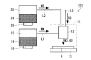
- FIG. 1 is an explanatory diagram showing a schematic configuration of a film forming apparatus for realizing a method for forming a back surface passivation film 5 (metal oxide film) according to Embodiment 1 of the present invention.
- a film forming apparatus 101 used in the film forming method of the present embodiment includes a reaction vessel 11, a heater 13 for heating the reaction vessel 11, a solution vessel 15 for storing a raw material solution 14, and a solution vessel 15. It comprises a mist generator 16 that mists the raw material solution 14, a solution container 25 that contains a reaction support solution 24 containing a reaction support agent, and a mist generator 26 that mists the reaction support solution 24 in the solution container 25.
- the reaction support agent is used for the purpose of promoting the reaction in the film formation step of the back surface passivation film 5 (metal oxide film) using the mist method.
- the raw material solution mist M1 which is the raw material solution 14 misted by the mist generator 16 is supplied to the reaction vessel 11 via the path L1 (first path).
- the support agent mist M2 which is the reaction support solution 24 misted by the mist generator 26, is supplied to the reaction vessel 11 via a path L2 (second path) provided independently of the path L1. .
- the raw material solution mist M1 and the support agent mist M2 supplied into the reaction vessel 11 via the paths L1 and L2 are mixed mist M3 obtained by mixing in the reaction vessel 11, and the P-type silicon substrate 4 in the reaction vessel 11 is obtained.
- the back surface passivation film 5 made of an aluminum oxide film can be formed on the back surface of the P-type silicon substrate 4 by spraying on the back surface of the P-type silicon substrate 4. At this time, the P-type silicon substrate 4 is placed on the heater 13 in the reaction vessel 11 in such a manner that the back surface is the top surface and the front surface is the bottom surface.
- the mixed mist M3 (a liquid raw material solution 14 having a small particle diameter and a reaction support solution 24) is placed in the reaction vessel 11 under atmospheric pressure.
- the back surface passivation film 5 is formed on the back surface of the P-type silicon substrate 4 by a predetermined reaction.
- the heater 13 is a heater or the like, and can heat the P-type silicon substrate 4 placed on the heater 13.
- the heater 13 is heated at the time of film formation by an external control unit (not shown) until reaching a temperature necessary for film formation of the back surface passivation film 5 made of an aluminum oxide film.
- the solution container 15 is filled with a raw material solution 14 serving as a material solution for forming the back surface passivation film 5.
- This raw material solution 14 is a material solution containing an aluminum (Al) element as a metal element.
- mist generator 16 for example, an ultrasonic atomizer can be employed.
- a mist generator 16 which is an ultrasonic atomizing device, mists the raw material solution 14 in the solution container 15 by applying ultrasonic waves to the raw material solution 14 in the solution container 15.
- the raw material solution mist M1 which is the misted raw material solution 14, is supplied toward the reaction vessel 11 through the path L1.
- the solution container 25 is filled with a reaction support solution 24 for aluminum element.
- the reaction support solution 24 is composed of an ammonia liquid (NH 3 ).
- the mist generator 26 having the same function as the mist generator 16 applies the ultrasonic wave to the reaction support solution 24 in the solution container 25 to mist the reaction support solution 24 in the solution container 25.
- the support agent mist M2 which is the mist-reacted solution support solution 24 is supplied toward the inside of the reaction vessel 11 through the path L2.
- FIG. 2 is an explanatory diagram specifically showing the reaction vessel 11 of the film forming apparatus 101 and its periphery in the first embodiment.
- the raw material solution mist M1 and the support agent mist M2 are supplied to the (film formation) nozzle 12 in the reaction vessel 11 through different paths L1 and L2, the raw material solution mist M1 and the support agent mist M2 are provided in the nozzle 12. And the mixed mist M3 is supplied from the nozzle 12 onto the upper surface of the P-type silicon substrate 4.
- the mixed mist M3 reacts on the back surface of the P-type silicon substrate 4 under atmospheric pressure which is being heated, and the back surface passivation film 5 is formed on the back surface of the P-type silicon substrate 4.
- ozone gas G9 is supplied to the nozzle 12 from the path L9. Therefore, ozone gas G9 is supplied from the nozzle 12 onto the back surface of the P-type silicon substrate 4 in addition to the mixed mist M3.
- the ozone gas G9 is used for promoting the reaction of the mixed mist M3. That is, the ozone gas G9 is used as a reaction promoting gas for the conventional indirect second method.
- a P-type silicon substrate 4 having a P-type conductivity is fabricated by introducing predetermined impurities into a silicon substrate whose constituent material is crystalline silicon. Then, the P-type silicon substrate 4 is placed on the heater 13 in the reaction vessel 11. At this time, the P-type silicon substrate 4 is placed on the heater 13 in such a manner that the back surface is the top surface and the front surface is the bottom surface, and the inside of the reaction vessel 11 is set to atmospheric pressure.
- the P-type silicon substrate 4 placed on the heater 13 is heated by the heater 13 until reaching the film formation temperature of the back surface passivation film 5 made of an aluminum oxide film, and the P-type silicon is formed at the film formation temperature. The temperature of the substrate 4 is maintained.
- the raw material solution mist M1 is obtained by making the raw material solution 14 mist by the mist generator 16 in the solution container 15.
- the raw material solution mist M1 liquid raw material solution 14 having a small particle size
- the raw material solution 14 contains aluminum as a metal source.
- the raw material solution 14 containing aluminum as a metal element is misted to obtain the raw material solution mist M1.
- the reaction support solution 24 is misted by the mist generator 26 to obtain the support agent mist M2.
- the support agent mist M2 liquid reaction support solution 24 having a small particle diameter
- ammonia water is used as the reaction support solution 24.
- the reaction support solution 24 containing the reaction support agent for forming aluminum oxide is misted to obtain the support agent mist M2.
- the raw material solution mist M1 and the support agent mist M2 are supplied to the nozzle 12 provided in the reaction vessel 11 via the paths L1 and L2 (first and second paths). Thereafter, the raw material solution mist M1 and the support agent mist M2 are mixed in the nozzle 12 to obtain a mixed mist M3. And mixed mist M3 is supplied on the back surface (one main surface) of the P-type silicon substrate 4 in a heated state. Further, ozone gas G9 is also supplied from the nozzle 12 onto the back surface of the P-type silicon substrate 4.
- the back surface passivation film 5 made of aluminum oxide, which is a metal oxide film, is sprayed onto the back surface of the heated P-type silicon substrate 4 under atmospheric pressure to spray the mixed mist M3 onto the P-type silicon substrate 4.
- a film can be formed on the back surface of the film.
- the back surface passivation film 5 can be formed at a relatively low temperature by reducing the reaction energy required for forming the back surface passivation film 5 by the support agent mist M2 contained in the mixed mist M3.
- the ozone gas G9 is also supplied onto the back surface of the P-type silicon substrate 4, the decomposition and oxidation of the material compound of the mixed mist M3 can be promoted.
- the solar cell structure shown in FIG. 6 is manufactured.
- the back surface passivation film 5 is formed after the surface passivation film 2 and the N-type silicon layer 3 are formed, and then the front surface electrode 1 and the back surface electrode 6 are formed. Note that the order of forming the front surface passivation film 2 and the back surface passivation film 5 may be reversed.
- FIG. 3 is a graph showing the effect of the method for forming the back surface passivation film 5 of the first embodiment.
- the back surface passivation film 5 formed by the film forming method of the first embodiment is significantly (about 5 times) compared to the back surface passivation film 5 formed by the conventional film forming method. It can be seen that the breakdown electric field strength is improved.
- the film formation method for the back surface passivation film 5 (metal oxide film) in the method for manufacturing the solar cell of the first embodiment is the mist method (that is, the film formation method for spraying the mixed mist M3 under atmospheric pressure). ) To form a back surface passivation film 5 on the back surface of the P-type silicon substrate 4.
- the method for forming the back surface passivation film 5 of the first embodiment provides an environment in which the mixed mist M3 is obtained by mixing the raw material solution mist M1 and the support agent mist M2 in the reaction vessel 11. As a result, the film formation rate of the back surface passivation film 5 can be increased to improve the production efficiency.
- the reaction energy for forming the back surface passivation film 5 can be reduced by the mixed mist M3 containing the support agent mist M2, the temperature is lower than that when the film is formed only by the raw material solution mist M1.
- a back surface passivation film 5 can be formed.
- the raw material solution mist M1 and the support agent mist M2 can be mixed in the film forming nozzle 12 and the mixed mist M3 can be reliably supplied onto the back surface of the P-type silicon substrate 4, back surface passivation.
- the production efficiency of the membrane 5 can be reliably improved.
- the reaction between the raw material solution mist M1 and the support agent mist M2 is performed in the reaction container 11. It will be done for the first time. Therefore, the raw material solution mist M1 that prevents the back surface passivation film 5 from being formed during the supply of the raw material solution mist M1 and the support agent mist M2 in the solution container 15, the solution container 25, or via the paths L1 and L2. A reaction product with the support agent mist M2 is not generated.
- the film quality of the back surface passivation film 5 can be improved.
- the atmosphere in the reaction vessel 11 has a density 1000 times higher than that of the gaseous support agent used in the conventional second method. A real atmosphere can be realized. For this reason, the high-quality back surface passivation film 5 can be produced even in a low-temperature heating state as compared with the conventional second method.
- the decomposition and oxidation of the material compound of the mixed mist M3 can be promoted. it can.
- the back surface passivation film 5 can be formed on the back surface of the P-type silicon substrate 4 even in a low temperature heating state.
- the film quality effect of the metal oxide film (back surface passivation film 5) described above is particularly noticeable when the metal element contained in the raw material solution 14 is aluminum and the back surface passivation film 5 made of aluminum oxide is formed.
- the back surface passivation film 5 made of aluminum oxide is formed, it is desirable to use the above-described ammonia water as the reaction support solution 24 or a solution containing hydrochloric acid instead of the ammonia water.
- the raw material solution 14 and the reaction support solution 24 are misted in separate solution containers 15 and 25, and the generated raw material solution mist M1 and support agent mist M2 are converted into reaction containers.
- the back surface passivation film 5 is formed after the mixed mist M3 is obtained in the nozzle 12 by supplying the nozzle 12 provided in the nozzle 12 through different paths L1 and L2.
- the raw material solution mist M1 and the support agent mist M2 are not efficiently mixed, and the mixed state is not good. It is sufficient that the mixed mist M3 does not have the desired properties. Therefore, when the back surface passivation film 5 is formed by the mixed mist M3 obtained in the nozzle 12, there remains a problem that the high-quality back surface passivation film 5 cannot be obtained reliably.
- the solution of the above problem is a method for forming the back surface passivation film 5 according to the second embodiment described below.
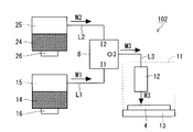
- FIG. 4 is an explanatory diagram showing a schematic configuration of a film forming apparatus for realizing the method for forming the back surface passivation film 5 according to the second embodiment of the present invention.
- description of the same configuration as that of the film forming apparatus 101 of Embodiment 1 shown in FIGS. 1 and 2 will be omitted as appropriate, and description will be made centering on a configuration different from that of Embodiment 1.
- the film forming apparatus 102 used in the film forming method of the present embodiment is characterized in that a mixing container 8 is provided between the paths L1 and L2 and the reaction container 11. That is, the mixing container 8 has two input parts I1 and I2 and one output part O3, the input part I1 is connected to the path L1, the input part I2 is connected to the path L2, and the output part O3 is connected to the path L3 ( The third path) and the path L3 is connected to the nozzle 12 in the reaction vessel 11.
- the raw material solution mist M1 and the support agent mist M2 are supplied to the mixing container 8 through paths L1 and L2.
- the raw material solution mist M1 and the support agent mist M2 are mixed in the mixing container 8 and supplied to the nozzle 12 in the reaction container 11 via the path L3 as the mixing mist M3, and from the nozzle 12 on the back surface of the P-type silicon substrate 4 Is supplied with the mixed mist M3.
- the mixed mist M3 is supplied from the nozzle 12 into the reaction vessel 11 under atmospheric pressure as in the first embodiment, By the reaction, a back surface passivation film 5 is formed on the back surface of the P-type silicon substrate 4.
- the mixed mist M3 reacts on the back surface of the P-type silicon substrate 4 under atmospheric pressure which is being heated, and the back surface passivation film 5 is formed on the back surface of the P-type silicon substrate 4.
- the P-type silicon substrate 4 is placed on the heater 13 in the reaction vessel 11.
- the P-type silicon substrate 4 placed on the heater 13 is heated by the heater 13 until reaching the film formation temperature of the back surface passivation film 5 made of an aluminum oxide film, and the P-type silicon is formed at the film formation temperature. The temperature of the substrate 4 is maintained.
- the raw material solution mist M1 and the support agent mist M2 obtained through the mutually independent paths L1 and L2 are supplied into the mixing container 8. Thereafter, in the mixing container 8, a step of obtaining the mixed mist M3 by mixing the raw material solution mist M1 and the support agent mist M2 is executed.
- the mixed mist M3 is supplied to the nozzle 12 in the reaction vessel 11 through a mist output port 83O (mixed mist output port) and a path L3 (third path).
- the mixed mist M 3 is supplied from the nozzle 12 to the back surface of the P-type silicon substrate 4 that is heated under atmospheric pressure.
- a back surface passivation film 5 made of an aluminum oxide film is formed on the back surface of the P-type silicon substrate 4.
- the P-type silicon substrate 4 is heated while supplying the mixed mist M3 obtained in the mixing vessel 8 to the back surface (one main surface) of the P-type silicon substrate 4 through the nozzle 12 in the reaction vessel 11.
- the film-forming step which forms the back surface passivation film 5 on the back surface of the P-type silicon substrate 4 is performed.
- the back surface passivation film 5 is supplied by supplying the mixed mist M3 obtained in the mixing container 8 into the reaction container 11 provided independently of the mixing container 8 when the film forming step is performed. It is possible to improve the production efficiency by increasing the film forming speed of the film.
- the raw material solution mist M1 is obtained by obtaining the mixed mist M3 obtained by mixing the raw material solution mist M1 and the support agent mist M2 in the mixing container 8.
- the mixed mist M3 in a state where the support agent mist M2 is sufficiently reacted can be obtained stably.
- the film quality of the back surface passivation film 5 formed in the film forming step can be improved.
- the raw material solution mist M1 and the support agent mist M2 are obtained in the solution container 15 and the solution container 25 independent from each other, and the reaction between the raw material solution mist M1 and the support agent mist M2 is performed in the mixing container 8 for the first time. Is called. Therefore, as in the conventional film forming apparatus 200 shown in FIG. 7, the raw material solution mist M1 (raw material solution 18) and the support agent mist M2 (reaction supporting solution 24) are mixed before the mixed mist M3 generation step is executed. By reliably avoiding the phenomenon of unnecessarily reacting, the film quality of the back surface passivation film 5 can be kept high.
- the ozone gas G9 is supplied to the nozzle 12 in the same manner as the film forming apparatus 101 according to the first embodiment, and the nozzle 12 supplies the ozone gas G9 onto the back surface of the P-type silicon substrate 4.
- a configuration in which ozone gas G9 is supplied in addition to the mixed mist M3 may be employed.
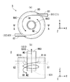
- FIG. 5 is an explanatory view showing the details of the structure of the mixing container 8 shown in FIG. 4, FIG. 5 (a) is a top view, and FIG. 5 (b) is a cross-sectional view taken along the line AA of FIG. It is sectional drawing shown.
- FIGS. 5A and 5B shows an XYZ orthogonal coordinate system.
- the mixing container 8 includes a container body 80, mist supply units 81 and 82 (first and second mist supply units), and a mist extraction unit 83.
- the container body 80 has a cylindrical shape in which a space is formed.
- the area inside the container main body 80 is a circular broken line portion in FIG. 5A and a region inside the rectangular broken line portion in FIG. 5B.
- the cylindrical hollow mist extraction portion 83 having an internal cavity is disposed so as to be inserted into the container main body 80 through an opening provided on the upper surface of the container main body 80.
- the gap between the mist takeout part 83 and the container body 80 is sealed. Note that a hollow portion in the mist takeout portion 83 becomes an internal path R83.
- the mist take-out portion 83 is inserted from the upper surface of the container main body 80, and a mist output port 83O (corresponding to the output portion O3 in FIG. 4) of the upper (+ Z direction side) upper surface opening exists outside the container main body 80.
- a mist input port 83I (mixed mist input port) on the lower ( ⁇ Z direction side) lower surface opening exists inside the container body 80 and is disposed at a predetermined height from the bottom surface of the container body 80. .
- the mist take-out portion 83 is provided at the center of the container body 80 in plan view.
- the mist take-out part 83 configured as described above receives the mixed mist M3 obtained in the container main body 80 from the mist input port 83I, passes the internal path R83, and removes the mixed mist M3 from the mist output port 83O (mixed mist output port).
- the mixed mist M3 output from the mist output port 83O of the mist extraction part 83 is supplied into the reaction vessel 11 via the path L3.
- the space between the inner peripheral portion of the side surface of the container body 80 (the portion shown in a circle by the broken line in FIG. 5) and the outer peripheral portion of the side surface of the mist takeout portion 83 is a plan view.
- an outer peripheral path R80 (mixing path) is provided in a circumferential shape.
- mist supply parts 81 and 82 each having a cavity inside each side surface of the container body 80 so as to supply the raw material solution mist M1 and the support agent mist M2 along the tangential direction of the inner periphery of the side surface of the container body 80.
- Paths L1 and L2 are connected to mist input ports 81I and 82I (corresponding to input portions I1 and I2 in FIG. 4), which are distal end portions of container body 80 in mist supply portions 81 and 82, respectively.
- a mist supply unit 81 is provided in the vicinity of the top (+ Y direction) apex of the container body 80 in a plan view, and the raw material solution mist M1 is placed in the ⁇ X direction (above). (The tangential direction near the top vertex).
- a mist supply unit 82 is provided in the vicinity of the apex of the lower portion ( ⁇ Y direction) of the container body 80 in parallel with the X direction, and the support agent mist M2 is aligned along the + X direction (tangential direction near the lower apex). Supply.
- the mist supply parts 81 and 82 are provided at the same formation height (height in the Z direction) on the side surface of the container body 80, and the mist input port 83I is provided at a formation height lower than the mist supply parts 81 and 82.
- the method of forming the back surface passivation film 5 according to the second embodiment can exhibit the following effects.
- the raw material solution mist M1 and the support agent mist M2 are mixed while circulating in the outer peripheral path R80 to obtain the mixed mist M3, as in the first embodiment.
- the mixed mist M3 having a desired property can be reliably obtained.
- the mist supply parts 81 and 82 have the same formation height on the side surface of the container body 80. However, even if there is a difference in the formation height between the mist supply parts 81 and 82, the mist supply part 81 , 82 to ensure a sufficient height difference between the lower mist supply section and the mist input port 83I (a height difference that can secure a sufficient reaction time to obtain the mixed mist M3), Similar effects can be achieved.
- the raw material solution mist M1 and the support agent mist are formed in the outer peripheral path R80 formed in a circular shape in a plan view by a space between the inner peripheral portion of the side surface of the container body 80 and the outer peripheral portion of the side surface of the mist take-out portion 83.
- Stirring can be performed while rotating M2. That is, the raw material solution mist M1 and the support agent mist M2 can be guided to the lower mist input port 83I while being rotated counterclockwise in a plan view and stirred.
- a mixed mist M3 obtained by efficiently mixing the raw material solution mist M1 and the support agent mist M2 can be obtained on the outer peripheral path R80.
- both the inner peripheral portion of the side surface of the container body 80 and the outer peripheral portion of the side surface of the mist extracting portion 83 are both circular and the outer peripheral path R80 is provided in a circular shape in plan view is employed.
- both the inner peripheral portion of the side surface of the container body 80 and the outer peripheral portion of the side surface of the mist take-out portion 83 are both pentagonal or more polygonal (preferably regular polygonal), and the outer periphery of the polygon is viewed in plan view.
- An outer peripheral path may be provided, and a similar effect can be achieved.
- mist supply parts 81 and 82 are provided on the side surface of the container body 80 so as to supply the raw material solution mist M1 and the support agent mist M2 along the tangential direction of the inner peripheral part of the side surface of the container body 80. For this reason, since the raw material solution mist M1 and the support agent mist M2 can be efficiently rotated from the beginning of supply from the mist supply parts 81 and 82 into the outer peripheral path R80, the raw material solution mist M1 and the support agent mist M2 It is possible to obtain a mixed mist M3 in which is mixed more efficiently.
- an example of manufacturing the back surface passivation film 5 on the back surface of the P-type silicon substrate 4 in the solar cell manufacturing method as a method for forming the metal oxide film formed on one main surface of the substrate.
- the present invention is not limited to the example described above.
- an insulating substrate such as a glass substrate may be used as a substrate other than the P-type silicon substrate 4, and a metal oxide film may be formed for purposes other than the passivation film. That is, the present invention can be applied to all metal oxide film forming methods for forming a metal oxide film on one main surface of a substrate using a mist method, and the performance of a metal oxide film itself such as an aluminum oxide film. There is an improvement effect.
- aluminum is shown as the metal source of the raw material solution 14, but any material solution in which a metal salt, a metal complex, or a metal alkoxide compound is dissolved may be used.
- the metal source contained in the raw material solution 14 is It can be arbitrarily selected according to the use of the formed metal oxide film.
- aluminum (Al) for example, titanium (Ti), zinc (Zn), indium (In), tin (Sn), or at least one of these can be employed as the metal source. .
- mist supply parts 81 and 82 are provided separately for the raw material solution mist M1 and the support agent mist M2, the raw material solution mist M1 and the support agent mist M2 are commonly received and supplied from the same location in the outer peripheral path R80.
- One common mist supply unit may be provided instead of the mist supply units 81 and 82.
Landscapes
- Chemical & Material Sciences (AREA)
- Engineering & Computer Science (AREA)
- Organic Chemistry (AREA)
- Chemical Kinetics & Catalysis (AREA)
- General Chemical & Material Sciences (AREA)
- Materials Engineering (AREA)
- Mechanical Engineering (AREA)
- Metallurgy (AREA)
- Inorganic Chemistry (AREA)
- Dispersion Chemistry (AREA)
- Formation Of Insulating Films (AREA)
- Photovoltaic Devices (AREA)
- Chemical Vapour Deposition (AREA)
- Life Sciences & Earth Sciences (AREA)
- Sustainable Development (AREA)
- Sustainable Energy (AREA)
- Oxygen, Ozone, And Oxides In General (AREA)
- Compounds Of Alkaline-Earth Elements, Aluminum Or Rare-Earth Metals (AREA)
Abstract
Description
図6は、本実施の形態(実施の形態1,実施の形態2)である金属酸化膜の製造方法を用いて製造される太陽電池構造を示す断面図である。
図1は、この発明の実施の形態1である、裏面パッシベーション膜5(金属酸化膜)の成膜方法を実現するための成膜装置の概略構成を示す説明図である。
次に、実施の形態1の裏面パッシベーション膜5(酸化アルミニウム膜)の成膜方法について説明する。
上述した実施の形態1は、原料溶液14と反応支援溶液24とを別々の溶液容器15及び溶液容器25内でミスト化させ、発生したそれぞれの原料溶液ミストM1及び支援剤ミストM2を、反応容器11内に設けられたノズル12へ異なる経路L1及びL2を介して供給し、ノズル12内にて混合ミストM3を得た後に裏面パッシベーション膜5の成膜を行う方法である。
図4は、この発明の実施の形態2である、裏面パッシベーション膜5の成膜方法を実現するための成膜装置の概略構成を示す説明図である。以下、図1及び図2で示した実施の形態1の成膜装置101と同様な構成の説明を適宜省略して、実施の形態1と異なる構成を中心に説明する。
次に、実施の形態2である、裏面パッシベーション膜5(酸化アルミニウム膜)の成膜方法について説明する。なお、実施の形態1と同じ内容については適宜説明を省略する。
図5は図4で示した混合容器8の構造の詳細を示す説明図であり、図5(a) が上面図であり、図5(b) が図5(a) のA-A断面を示す断面図である。図5(a) ,(b) それぞれにXYZ直交座標系を示している。
なお、上述した実施の形態では、基板の一方主面上に形成する金属酸化膜の成膜方法として、太陽電池の製造方法におけるP型シリコン基板4の裏面上に裏面パッシベーション膜5を製造する例を示したが、上述した例に限定されないことは勿論である。例えば、P型シリコン基板4以外の基板としてガラス基板のような絶縁性基板を用いてもよく、パッシベーション膜以外の目的で金属酸化膜を形成してもよい。すなわち、本願発明は、ミスト法を用いて基板の一方主面上に金属酸化膜を成膜する金属酸化膜の成膜方法全般に適用可能であり、酸化アルミニウム膜等の金蔵酸化膜そのものの性能向上効果を奏している。
5 裏面パッシベーション膜
8 混合容器
11 反応容器
12 ノズル
13 加熱器
14 原料溶液
15,25 溶液容器
16,26 ミスト化器
24 反応支援溶液
80 容器本体
81,82 ミスト供給部
83 ミスト取り出し部
101,102 成膜装置
L1~L3 経路
R80 外周経路
Claims (5)
- (a) 第1の容器(15)内において、金属元素を含む原料溶液(14)をミスト化させて原料溶液ミスト(M1)を得るステップと、
(b) 前記第1の容器と独立した第2の容器(25)内において、前記金属元素用の反応支援剤を含む反応支援溶液(24)をミスト化させて支援剤ミスト(M2)を得るステップと、
(c) 互いに独立した第1及び第2の経路(L1,L2)を介して前記原料溶液ミスト及び前記支援剤ミストを受ける混合容器(8)内において、前記原料溶液ミストと前記支援剤ミストとを混合して混合ミスト(M3)を得るステップと、
(d) 前記ステップ(c) で得た前記混合ミストを反応容器内における基板の一方主面上に供給しつつ、前記基板(4)を加熱して、前記基板の一方主面上に前記金属元素を含む金属酸化膜を成膜するステップとを備える、
金属酸化膜の成膜方法。 - 請求項1記載の金属酸化膜の成膜方法であって、
前記混合容器は、
容器本体(80)と、
前記第1及び第2の経路に接続され、前記原料溶液ミスト及び前記支援剤ミストを前記容器本体内に供給する第1及び第2のミスト供給部(81,82)と、
前記容器本体の内部に設けられた混合ミスト入力口(83I)及び前記容器本体の外部に設けられた混合ミスト出力口(83O)を有し、前記混合ミスト入力口から前記混合ミストを受け、前記混合ミスト出力口から前記混合ミストを取り出すミスト取り出し部(83)とを含み、前記混合ミスト出力口から得られる前記混合ミストが第3の経路(L3)を介して前記反応容器内に供給され、
前記容器本体は内部に、前記第1及び第2のミスト供給部から供給された前記原料溶液ミスト及び前記支援剤ミストを流通させつつ前記混合ミスト入力口に導く混合経路(R80)を有する、
金属酸化膜の成膜方法。 - 請求項2記載の金属酸化膜の成膜方法であって、
前記第1及び第2のミスト供給部は前記容器本体において互いに同一の形成高さに設けられ、前記混合ミスト入力口は前記第1及び第2のミスト供給部より低い形成高さに設けられる、
金属酸化膜の成膜方法。 - 請求項3記載の金属酸化膜の成膜方法であって、
前記容器本体は円筒形状を呈し、
前記ミスト取り出し部は前記容器本体内の平面視中央部に設けられ、内部空洞の円筒形状を呈し、前記混合ミスト入力口を下面に有し、前記混合ミスト出力口を上面に有し、
前記混合経路は、前記容器本体の側面内周部と前記ミスト取り出し部の側面外周部との間の空間によって平面視して円周状に形成される、
金属酸化膜の成膜方法。 - 請求項4記載の金属酸化膜の成膜方法であって、
前記第1及び第2のミスト供給部は、
前記容器本体の側面内周部の接線方向に沿って前記原料溶液ミスト及び前記支援剤ミストを供給するように設けられる、
金属酸化膜の成膜方法。
Priority Applications (8)
| Application Number | Priority Date | Filing Date | Title |
|---|---|---|---|
| KR1020177033932A KR102074049B1 (ko) | 2015-06-18 | 2015-06-18 | 금속 산화막의 성막 방법 |
| CN201580080989.4A CN107683347B (zh) | 2015-06-18 | 2015-06-18 | 金属氧化膜的成膜方法 |
| PCT/JP2015/067536 WO2016203595A1 (ja) | 2015-06-18 | 2015-06-18 | 金属酸化膜の成膜方法 |
| US15/736,351 US10290762B2 (en) | 2015-06-18 | 2015-06-18 | Metal oxide film formation method |
| HK18105400.3A HK1245854B (zh) | 2015-06-18 | 金属氧化膜的成膜方法 | |
| DE112015006632.2T DE112015006632B4 (de) | 2015-06-18 | 2015-06-18 | Verfahren zur Bildung eines Metalloxidfilms |
| JP2017524223A JP6473231B2 (ja) | 2015-06-18 | 2015-06-18 | 金属酸化膜の成膜方法 |
| TW104126686A TWI589721B (zh) | 2015-06-18 | 2015-08-17 | 金屬氧化膜的成膜方法 |
Applications Claiming Priority (1)
| Application Number | Priority Date | Filing Date | Title |
|---|---|---|---|
| PCT/JP2015/067536 WO2016203595A1 (ja) | 2015-06-18 | 2015-06-18 | 金属酸化膜の成膜方法 |
Publications (1)
| Publication Number | Publication Date |
|---|---|
| WO2016203595A1 true WO2016203595A1 (ja) | 2016-12-22 |
Family
ID=57545544
Family Applications (1)
| Application Number | Title | Priority Date | Filing Date |
|---|---|---|---|
| PCT/JP2015/067536 Ceased WO2016203595A1 (ja) | 2015-06-18 | 2015-06-18 | 金属酸化膜の成膜方法 |
Country Status (7)
| Country | Link |
|---|---|
| US (1) | US10290762B2 (ja) |
| JP (1) | JP6473231B2 (ja) |
| KR (1) | KR102074049B1 (ja) |
| CN (1) | CN107683347B (ja) |
| DE (1) | DE112015006632B4 (ja) |
| TW (1) | TWI589721B (ja) |
| WO (1) | WO2016203595A1 (ja) |
Cited By (3)
| Publication number | Priority date | Publication date | Assignee | Title |
|---|---|---|---|---|
| JP2020196930A (ja) * | 2019-06-03 | 2020-12-10 | トヨタ自動車株式会社 | ミスト生成装置、成膜装置、及び成膜装置を用いた成膜方法 |
| JP2022093208A (ja) * | 2020-12-12 | 2022-06-23 | 高知県公立大学法人 | Ga2O3薄膜の製造方法 |
| JP2023151328A (ja) * | 2022-03-31 | 2023-10-16 | 音羽電機工業株式会社 | 酸化ビスマス膜の成膜方法 |
Citations (6)
| Publication number | Priority date | Publication date | Assignee | Title |
|---|---|---|---|---|
| JPH07211643A (ja) * | 1994-01-20 | 1995-08-11 | Hitachi Electron Eng Co Ltd | Cvd装置の反応ガス混合器 |
| JPH09235675A (ja) * | 1995-12-28 | 1997-09-09 | Ebara Corp | 液体原料気化装置 |
| JP2001509641A (ja) * | 1997-07-14 | 2001-07-24 | シメトリックス・コーポレーション | 化学気相成長法によって薄膜を製造する方法と装置 |
| JP2008078113A (ja) * | 2006-08-25 | 2008-04-03 | Fujikura Ltd | 透明導電性基板の製造装置 |
| WO2011151889A1 (ja) * | 2010-06-01 | 2011-12-08 | 東芝三菱電機産業システム株式会社 | 金属酸化膜の成膜装置、金属酸化膜の製造方法および金属酸化膜 |
| WO2012124047A1 (ja) * | 2011-03-15 | 2012-09-20 | 東芝三菱電機産業システム株式会社 | 成膜装置 |
Family Cites Families (7)
| Publication number | Priority date | Publication date | Assignee | Title |
|---|---|---|---|---|
| EP1412067A2 (en) | 2001-05-07 | 2004-04-28 | Uop Llc | Apparatus for mixing and reacting at least two fluids |
| GB2415707A (en) * | 2004-06-30 | 2006-01-04 | Arima Optoelectronic | Vertical hydride vapour phase epitaxy deposition using a homogenising diaphragm |
| US7862683B2 (en) * | 2005-12-02 | 2011-01-04 | Tokyo Electron Limited | Chamber dry cleaning |
| US20100273291A1 (en) * | 2009-04-28 | 2010-10-28 | Applied Materials, Inc. | Decontamination of mocvd chamber using nh3 purge after in-situ cleaning |
| CN102414801A (zh) * | 2009-08-27 | 2012-04-11 | 应用材料公司 | 在原位腔室清洁后的处理腔室去污方法 |
| JP5711274B2 (ja) * | 2011-01-31 | 2015-04-30 | 旭化成ケミカルズ株式会社 | 混合液製造装置、混合液調製方法、触媒の調製方法、及び不飽和ニトリルの製造方法 |
| KR20160098523A (ko) | 2012-02-08 | 2016-08-18 | 도시바 미쓰비시덴키 산교시스템 가부시키가이샤 | 금속산화막의 제조 방법 및 금속산화막 |
-
2015
- 2015-06-18 DE DE112015006632.2T patent/DE112015006632B4/de active Active
- 2015-06-18 WO PCT/JP2015/067536 patent/WO2016203595A1/ja not_active Ceased
- 2015-06-18 US US15/736,351 patent/US10290762B2/en active Active
- 2015-06-18 CN CN201580080989.4A patent/CN107683347B/zh active Active
- 2015-06-18 KR KR1020177033932A patent/KR102074049B1/ko active Active
- 2015-06-18 JP JP2017524223A patent/JP6473231B2/ja active Active
- 2015-08-17 TW TW104126686A patent/TWI589721B/zh active
Patent Citations (6)
| Publication number | Priority date | Publication date | Assignee | Title |
|---|---|---|---|---|
| JPH07211643A (ja) * | 1994-01-20 | 1995-08-11 | Hitachi Electron Eng Co Ltd | Cvd装置の反応ガス混合器 |
| JPH09235675A (ja) * | 1995-12-28 | 1997-09-09 | Ebara Corp | 液体原料気化装置 |
| JP2001509641A (ja) * | 1997-07-14 | 2001-07-24 | シメトリックス・コーポレーション | 化学気相成長法によって薄膜を製造する方法と装置 |
| JP2008078113A (ja) * | 2006-08-25 | 2008-04-03 | Fujikura Ltd | 透明導電性基板の製造装置 |
| WO2011151889A1 (ja) * | 2010-06-01 | 2011-12-08 | 東芝三菱電機産業システム株式会社 | 金属酸化膜の成膜装置、金属酸化膜の製造方法および金属酸化膜 |
| WO2012124047A1 (ja) * | 2011-03-15 | 2012-09-20 | 東芝三菱電機産業システム株式会社 | 成膜装置 |
Cited By (5)
| Publication number | Priority date | Publication date | Assignee | Title |
|---|---|---|---|---|
| JP2020196930A (ja) * | 2019-06-03 | 2020-12-10 | トヨタ自動車株式会社 | ミスト生成装置、成膜装置、及び成膜装置を用いた成膜方法 |
| JP7228160B2 (ja) | 2019-06-03 | 2023-02-24 | 株式会社デンソー | ミスト生成装置、成膜装置、及び成膜装置を用いた成膜方法 |
| JP2022093208A (ja) * | 2020-12-12 | 2022-06-23 | 高知県公立大学法人 | Ga2O3薄膜の製造方法 |
| JP2023151328A (ja) * | 2022-03-31 | 2023-10-16 | 音羽電機工業株式会社 | 酸化ビスマス膜の成膜方法 |
| JP7814696B2 (ja) | 2022-03-31 | 2026-02-17 | 音羽電機工業株式会社 | 酸化ビスマス膜の成膜方法 |
Also Published As
| Publication number | Publication date |
|---|---|
| CN107683347B (zh) | 2020-05-15 |
| US20180190859A1 (en) | 2018-07-05 |
| DE112015006632B4 (de) | 2023-09-21 |
| DE112015006632T5 (de) | 2018-03-01 |
| CN107683347A (zh) | 2018-02-09 |
| TWI589721B (zh) | 2017-07-01 |
| KR102074049B1 (ko) | 2020-02-05 |
| TW201700769A (zh) | 2017-01-01 |
| KR20170141227A (ko) | 2017-12-22 |
| JPWO2016203595A1 (ja) | 2018-02-01 |
| HK1245854A1 (zh) | 2018-08-31 |
| US10290762B2 (en) | 2019-05-14 |
| JP6473231B2 (ja) | 2019-02-20 |
Similar Documents
| Publication | Publication Date | Title |
|---|---|---|
| JP5645191B2 (ja) | 金属酸化膜の成膜方法および金属酸化膜 | |
| JP6473231B2 (ja) | 金属酸化膜の成膜方法 | |
| WO2016203594A1 (ja) | 金属酸化膜の成膜方法 | |
| WO2011027425A1 (ja) | 金属酸化膜の成膜方法、金属酸化膜および金属酸化膜の成膜装置 | |
| TWI593130B (zh) | 太陽能電池的製造方法 | |
| JP2019071479A (ja) | 金属酸化膜の成膜方法 | |
| HK1245854B (zh) | 金属氧化膜的成膜方法 | |
| HK1245855B (zh) | 金属氧化膜的成膜方法 | |
| KR102039611B1 (ko) | 기판형 태양 전지 및 그의 제조 방법, 기판형 태양 전지의 도핑 방법 및 장치 | |
| TW201023387A (en) | Method for manufacturing thin film type solar cell | |
| TWI607578B (zh) | 太陽電池之製造方法 |
Legal Events
| Date | Code | Title | Description |
|---|---|---|---|
| 121 | Ep: the epo has been informed by wipo that ep was designated in this application |
Ref document number: 15895615 Country of ref document: EP Kind code of ref document: A1 |
|
| ENP | Entry into the national phase |
Ref document number: 2017524223 Country of ref document: JP Kind code of ref document: A |
|
| ENP | Entry into the national phase |
Ref document number: 20177033932 Country of ref document: KR Kind code of ref document: A |
|
| WWE | Wipo information: entry into national phase |
Ref document number: 112015006632 Country of ref document: DE |
|
| 122 | Ep: pct application non-entry in european phase |
Ref document number: 15895615 Country of ref document: EP Kind code of ref document: A1 |