WO2016199839A1 - 電動パワーステアリング装置 - Google Patents
電動パワーステアリング装置 Download PDFInfo
- Publication number
- WO2016199839A1 WO2016199839A1 PCT/JP2016/067179 JP2016067179W WO2016199839A1 WO 2016199839 A1 WO2016199839 A1 WO 2016199839A1 JP 2016067179 W JP2016067179 W JP 2016067179W WO 2016199839 A1 WO2016199839 A1 WO 2016199839A1
- Authority
- WO
- WIPO (PCT)
- Prior art keywords
- command value
- torque
- electric power
- steering
- control
- Prior art date
- Legal status (The legal status is an assumption and is not a legal conclusion. Google has not performed a legal analysis and makes no representation as to the accuracy of the status listed.)
- Ceased
Links
Images



Classifications
-
- B—PERFORMING OPERATIONS; TRANSPORTING
- B62—LAND VEHICLES FOR TRAVELLING OTHERWISE THAN ON RAILS
- B62D—MOTOR VEHICLES; TRAILERS
- B62D5/00—Power-assisted or power-driven steering
- B62D5/04—Power-assisted or power-driven steering electrical, e.g. using an electric servo-motor connected to, or forming part of, the steering gear
- B62D5/0457—Power-assisted or power-driven steering electrical, e.g. using an electric servo-motor connected to, or forming part of, the steering gear characterised by control features of the drive means as such
- B62D5/046—Controlling the motor
- B62D5/0463—Controlling the motor calculating assisting torque from the motor based on driver input
-
- B—PERFORMING OPERATIONS; TRANSPORTING
- B62—LAND VEHICLES FOR TRAVELLING OTHERWISE THAN ON RAILS
- B62D—MOTOR VEHICLES; TRAILERS
- B62D1/00—Steering controls, i.e. means for initiating a change of direction of the vehicle
- B62D1/24—Steering controls, i.e. means for initiating a change of direction of the vehicle not vehicle-mounted
- B62D1/28—Steering controls, i.e. means for initiating a change of direction of the vehicle not vehicle-mounted non-mechanical, e.g. following a line or other known markers
- B62D1/286—Systems for interrupting non-mechanical steering due to driver intervention
-
- B—PERFORMING OPERATIONS; TRANSPORTING
- B62—LAND VEHICLES FOR TRAVELLING OTHERWISE THAN ON RAILS
- B62D—MOTOR VEHICLES; TRAILERS
- B62D15/00—Steering not otherwise provided for
- B62D15/02—Steering position indicators ; Steering position determination; Steering aids
- B62D15/021—Determination of steering angle
- B62D15/0235—Determination of steering angle by measuring or deriving directly at the electric power steering motor
-
- B—PERFORMING OPERATIONS; TRANSPORTING
- B62—LAND VEHICLES FOR TRAVELLING OTHERWISE THAN ON RAILS
- B62D—MOTOR VEHICLES; TRAILERS
- B62D15/00—Steering not otherwise provided for
- B62D15/02—Steering position indicators ; Steering position determination; Steering aids
- B62D15/025—Active steering aids, e.g. helping the driver by actively influencing the steering system after environment evaluation
- B62D15/0265—Automatic obstacle avoidance by steering
-
- B—PERFORMING OPERATIONS; TRANSPORTING
- B62—LAND VEHICLES FOR TRAVELLING OTHERWISE THAN ON RAILS
- B62D—MOTOR VEHICLES; TRAILERS
- B62D15/00—Steering not otherwise provided for
- B62D15/02—Steering position indicators ; Steering position determination; Steering aids
- B62D15/027—Parking aids, e.g. instruction means
- B62D15/0285—Parking performed automatically
-
- B—PERFORMING OPERATIONS; TRANSPORTING
- B62—LAND VEHICLES FOR TRAVELLING OTHERWISE THAN ON RAILS
- B62D—MOTOR VEHICLES; TRAILERS
- B62D6/00—Arrangements for automatically controlling steering depending on driving conditions sensed and responded to, e.g. control circuits
- B62D6/002—Arrangements for automatically controlling steering depending on driving conditions sensed and responded to, e.g. control circuits computing target steering angles for front or rear wheels
- B62D6/003—Arrangements for automatically controlling steering depending on driving conditions sensed and responded to, e.g. control circuits computing target steering angles for front or rear wheels in order to control vehicle yaw movement, i.e. around a vertical axis
-
- B—PERFORMING OPERATIONS; TRANSPORTING
- B62—LAND VEHICLES FOR TRAVELLING OTHERWISE THAN ON RAILS
- B62D—MOTOR VEHICLES; TRAILERS
- B62D6/00—Arrangements for automatically controlling steering depending on driving conditions sensed and responded to, e.g. control circuits
- B62D6/007—Arrangements for automatically controlling steering depending on driving conditions sensed and responded to, e.g. control circuits adjustable by the driver, e.g. sport mode
Definitions
- the present invention has functions of an automatic steering mode (parking assistance, obstacle avoidance, lane keeping, etc.) and a manual steering mode (normal steering), and an electric power that applies an assist force by a motor to a vehicle steering system.
- an automatic steering mode parking assistance, obstacle avoidance, lane keeping, etc.
- a manual steering mode normal steering
- an electric power that applies an assist force by a motor to a vehicle steering system.
- the steering device in particular, when switching from the angle control method of the automatic steering mode to the torque control method of the manual steering mode by gradual change, the gradual change time is made variable according to the command value difference between the angle control command value and the torque control command value.
- the present invention relates to an electric power steering apparatus.
- An electric power steering device that includes a motor control device and applies a steering assist force (assist force) to the steering mechanism of the vehicle by the rotational force of the motor is used to drive the motor driving force through a speed reducer, such as a gear or a belt. With this transmission mechanism, a steering assist force is applied to the steering shaft or the rack shaft.
- a conventional electric power steering apparatus performs feedback control of the motor current in order to accurately generate the torque of the steering assist force.
- the motor applied voltage is adjusted so that the difference between the steering assist command value (current command value) and the motor current detection value is small.
- the adjustment of the motor applied voltage is generally performed by PWM (pulse width). This is done by adjusting the duty of modulation) control.
- the column shaft 2 is provided with a torque sensor 10 that detects the steering torque of the handle 1, and a motor 20 that assists the steering force of the handle (steering wheel) 1 is connected to the column shaft 2 via the reduction gear 3. It is connected.
- the control unit (ECU) 30 that controls the electric power steering apparatus is supplied with electric power from the battery 13 and also receives an ignition key signal via the ignition key 11.
- the control unit 30 calculates a steering assist command value of an assist (steering assist) command based on the steering torque Ts detected by the torque sensor 10 and the vehicle speed Vs detected by the vehicle speed sensor 12, and obtains the steering assist command value.
- the current supplied to the motor 20 is controlled by the voltage control value Vref subjected to compensation or the like.
- the rudder angle sensor 14 is not essential and may not be provided, and may be obtained from a rotation sensor connected to the motor 20.
- the control unit 30 is connected to a CAN (Controller Area Network) 40 that exchanges various vehicle information, and the vehicle speed Vs can be received from the CAN 40.
- the control unit 30 can be connected to a non-CAN 41 that exchanges communications, analog / digital signals, radio waves, and the like other than the CAN 40.
- control unit 30 is mainly composed of a CPU (including an MPU, MCU, etc.). General functions executed by a program inside the CPU are shown in FIG. The configuration is as shown.
- the function and operation of the control unit 30 will be described with reference to FIG. 2.
- the steering torque Ts from the torque sensor 10 and the vehicle speed Vs from the vehicle speed sensor 12 are input to the current command value calculation unit 31, and the current command value calculation unit 31.
- the calculated current command value Iref1 is added by the adding unit 32A and the compensation signal CM from the compensating unit 34 for improving the characteristics, and the added current command value Iref2 is limited to the maximum value by the current limiting unit 33.
- the current command value Irefm whose maximum value is limited is input to the subtraction unit 32B and subtracted from the motor current detection value Im.
- the motor 20 is PWM driven via the inverter 37 with the PWM signal whose duty is calculated.
- the motor current value Im of the motor 20 is detected by the motor current detection means 38, and is input to the subtraction unit 32B and fed back.
- the compensating unit 34 adds the detected or estimated self-aligning torque (SAT) 34-3 to the inertia compensation value 34-2 by the adding unit 34-4, and further adds the convergence result to the convergence by the adding unit 34-5.
- the control value 34-1 is added, and the addition result is input to the adder 32A as a compensation signal CM to improve the characteristics.
- automatic steering control sets the target steering angle based on data from cameras (images) and distance sensors, and makes the actual steering angle follow the target steering angle. Is done.
- an actuator (motor) is controlled based on a relationship between a moving distance of a vehicle and a turning angle stored in advance.
- the parking assist device recognizes the parking space from a positioning sensor such as an around view monitor or an ultrasonic sensor, and outputs a steering angle command value (angle control command value) to the EPS side.
- the EPS guides the vehicle to the parking space by controlling the position of the actual steering angle so as to follow the steering angle command value.
- FIG. 3 shows a control system of an electric power steering apparatus having a parking assistance mode function.
- Various data are input to the automatic steering command apparatus 50 such as parking assistance from a camera and a positioning sensor (ultrasonic sensor, etc.).
- the support steering angle command value is input to the position control unit (angle control unit) 51 in the EPS actuator function via CAN or the like, and the parking support execution command is input to the parking support execution determination unit 52 in the EPS actuator function via CAN or the like. Entered.
- the parking assist execution determination unit 52 also receives the steering torque Ts from the EPS sensor.
- a steering angle sensor or an actual steering angle ⁇ r which is a steering angle signal from the outside, is input to the position control unit 51, and the determination result of the parking support execution determination unit 52 is input to the torque command value gradual change switching unit 54.
- the steering torque Ts of the EPS sensor is input to the torque control unit 53 in the EPS power assist function, and the steering assist torque command value Tc from the torque control unit 53 is input to the torque command value gradual change switching unit 54.
- the position control torque command value Tp from the position control unit 51 is also input to the torque command value gradual change switching unit 54, and the steering assist torque command value Tc and the position control torque command value Tp are determined according to the determination result of the parking support execution determination unit 52.
- the motor is switched and output as a motor torque command value, and the motor is driven and controlled via the current control system.
- position control unit 51 actually performs speed control, and is a position / speed control unit to which the steering angular speed is input, but is limited to position control here for convenience of explanation.
- the normal power assist is a torque control system
- it becomes an angle (position) control system such as a rudder angle.
- Patent Document 1 As for a method of shifting from conventional angle control (automatic steering) to torque control (manual control), there is an automatic steering device disclosed in, for example, Japanese Patent No. 3311277 (Patent Document 1).
- Patent Document 1 when the control amount of the actuator (motor) decreases with the shift from automatic steering control (angle control) to torque control.
- the control amount is linearly decreased from the value at the time of automatic steering control to the value at the time of torque control so that the steering reaction force received from the steering wheel by the driver does not change abruptly.
- Patent Document 1 since the automatic steering device of Patent Document 1 does not consider the difference between the angle control command value and the torque control command value, if the difference between the angle control command value and the torque control command value is large, the torque transmitted to the driver. There is a problem that the change is great and the safety is lowered and the user feels uncomfortable.
- the present invention has been made under the circumstances described above, and an object of the present invention is to provide an angle control command value in a gradual change process for switching the control method from angle control (automatic steering mode) to torque control (manual steering mode). It is an object of the present invention to provide a high-performance electric power steering device that is safe and has a reduced sense of incongruity by changing the gradual change time based on the command value difference between the torque control command value and the torque control command value.
- the present invention relates to an electric power steering apparatus having a torque sensor for detecting a steering torque and a motor control apparatus for controlling a motor for applying an assist torque for assisting steering to a steering mechanism of the vehicle.
- the motor control method is controlled between an angle control method for controlling according to an angle control command value in the automatic steering mode and a torque control method for controlling according to a torque control command value in the manual steering mode according to a predetermined switching opportunity. Achieved by making the gradual change time variable according to the command value difference between the angle control command value and the torque control command value when switching from the angle control method to the torque control method by gradual change. Is done.
- the object of the present invention is that the command value difference is an absolute value of a difference between the angle control command value and the torque control command value, or the predetermined switching trigger is ON / OFF of an automatic steering command.
- the ON / OFF of the automatic steering command is a parking assistance command, an obstacle avoidance command or a lane keep command, or the predetermined switching trigger is determined by an internal determination of the steering torque.
- the ON / OFF of the given switching command, or the gradual change time is changed linearly or nonlinearly according to the command value difference, or the gradual change is performed linearly or nonlinearly. This is achieved more effectively.
- the angle control command value is changed based on the command value difference between the torque control command value and the torque control command value.
- the command value difference is large, the gradual change time is set longer and the gradual switching is performed. For this reason, it is possible to provide a high-performance electric power steering device that is safe and has reduced discomfort to the driver.
- the command value difference which is the absolute value of the difference between the angle control command value in the automatic steering mode and the torque control command value in the manual steering mode is not considered at all.
- the value difference is large, the torque change transmitted to the driver is large, and there is a problem that the safety is lowered or the driver feels uncomfortable.
- an automatic steering ON / OFF switching opportunity for example, ON / OFF of a vehicle obstacle avoidance command, ON / OFF of a parking assistance command, ON / OFF of a switching command given by an internal determination of steering torque
- the automatic steering mode angle control method is switched to the manual steering mode torque control method, the gradual change time is made variable according to the command value difference (the gradual change time is lengthened when the command value difference is large). This realizes safe steering with a sense of incongruity suppressed.
- the automatic steering mode for obstacle avoidance it is necessary to recognize obstacles ahead by a camera or radar and avoid obstacles by steering.
- the control of the electric power steering apparatus is normally torque control, and angle control is performed when obstacles are avoided.
- the gradual change time is varied according to the command value difference.
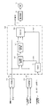
- FIG. 5 shows a configuration example of the present invention, in which the steering torque Ts and the vehicle speed Vs are input to the torque control unit 110, and the torque control unit 110 calculates a torque control command value TC based on the steering torque Ts and the vehicle speed Vs.
- the tire turning angle command value At and the actual turning angle Ar are input to the angle control unit 120, and the angle control unit 120 sets the angle control command value AC based on the tire turning angle command value At and the actual turning angle Ar.
- the torque control command value TC from the torque control unit 110 is input to the command value difference calculation unit 102 and the switching unit 104 in the switching control unit 100, and the angle control command value AC from the angle control unit 120 is input to the switching control unit 100.
- a vehicle obstacle avoidance signal Vf (logic “0” when normal, logic “1” when avoidance) as a switching opportunity is input to the determination unit 101 in the switching control unit 100, and the determination unit 101 receives the vehicle obstacle. It is determined whether the avoidance signal Vf has changed from “0” to “1” or “1” to “0”.
- the determination unit 101 outputs a determination signal DS2 when it is determined that the vehicle obstacle avoidance signal Vf has changed from “0” to “1”, and the determination signal DS2 is input to the switching unit 104.
- the determination unit 101 outputs a determination signal DS1 when it is determined that the vehicle obstacle avoidance signal Vf has changed from “1” to “0”, and the determination signal DS1 is input to the command value difference calculation unit 102. .
- the command value difference calculation unit 102 calculates a command value difference CD that is an absolute value of the difference between the torque control command value TC and the angle control command value AC. That is, the command value difference CD is calculated by the following formula 1.
- Command value difference CD
- the command value difference CD is input to the gradual change time calculation unit 103, and the gradual change time calculation unit 103 is a gradual change time according to the command value difference CD with an arithmetic expression as shown in characteristics A, B, and C in FIG. Tj is calculated. That is, the gradual change time Tj is calculated by the following formula 2.
- the output of the switching unit 104 is output as a motor command value MC, the motor command value MC is input to the current control system 130, and the assist motor 131 is driven and controlled via the current control system 130.
- the determination unit 101 determines that the vehicle obstacle avoidance signal Vf has changed from “1” to “0”, the determination unit 101 outputs the determination signal DS 2, and the determination signal DS 2 is input to the switching unit 104.
- the switching unit 104 has step characteristics as shown in FIG. 8, that is, when the determination signal DS2 is input at the time t1, the torque control (100%) is instantaneously switched to the angle control (100%).
- the determination unit 101 determines whether or not the vehicle obstacle avoidance signal Vf has changed from “0” to “1” (step S1), and the vehicle obstacle avoidance signal Vf has changed from “0” to “1”. Therefore, the determination unit 101 outputs a determination signal DS2, whereby the switching unit 104 switches from torque control to angle control according to the characteristics of FIG. 8 (step S2). Thereby, angle control is implemented.
- step S10 If it is not determined in step S1 that the vehicle obstacle avoidance signal Vf has changed from “0” to “1”, the determination unit 101 changes the vehicle obstacle avoidance signal Vf from “1” to “0”. It is determined whether or not (step S10).
- the determination unit 101 outputs the determination signal DS1, and the determination signal DS1 is input to the command value difference calculation unit 102.
- the command value difference calculation unit 102 calculates a command value difference CD that is an absolute value of the difference between the torque control command value TC and the angle control command value AC (step S11).
- the gradual change time calculation unit 103 inputs the gradual change time calculation unit 103, which has characteristics as shown in FIG.
- step S12 a gradual change time Tj that increases as the command value difference CD increases.
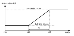
- the gradual change time Tj is input to the switching unit 104, and the switching unit 104 gradually switches from angle control to torque control by gradual change processing as shown in FIG. 7 according to the gradual change time Tj (step S13).
- step S10 if the vehicle obstacle avoidance signal Vf does not change from “1” to “0” in step S10, the current control is maintained (step S20).
- logic “0” is set when the vehicle obstacle avoidance signal Vf is normal
- logic “1” is set when the vehicle obstacle avoidance signal Vf is normal
- the logic “1” is set when it is normal
- the logic “0” is set when the vehicle is avoided.
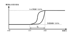
- the characteristics of the gradual change processing may be nonlinear gradual change characteristics as shown in FIG.
Landscapes
- Engineering & Computer Science (AREA)
- Chemical & Material Sciences (AREA)
- Combustion & Propulsion (AREA)
- Transportation (AREA)
- Mechanical Engineering (AREA)
- Physics & Mathematics (AREA)
- Mathematical Physics (AREA)
- Steering Control In Accordance With Driving Conditions (AREA)
- Power Steering Mechanism (AREA)
Abstract
【課題】角度制御から手動制御のトルク制御に制御方式を切替える徐変処理に際して、角度制御指令値とトルク制御指令値の指令値差に基づいて徐変時間を変更することにより、安全で違和感を低減した高性能な電動パワーステアリング装置を提供する。 【解決手段】操舵トルクを検出するトルクセンサと、操舵を補助するアシストトルクを車両の操舵機構に付与するモータを制御するモータ制御装置とを有する電動パワーステアリング装置において、所定の切替え契機に従って、自動操舵モードの角度制御指令値に応じて制御する角度制御方式と、手動操舵モードのトルク制御指令値に応じて制御するトルク制御方式との間でモータの制御方式を切替える機能を具備し、角度制御方式からトルク制御方式に徐変で切替えるとき、角度制御指令値と前記トルク制御指令値の指令値差に応じて徐変時間を可変する。
Description
本発明は、自動操舵モード(駐車支援、障害物回避、レーンキープ等)及び手動操舵モード(通常操舵)の機能を有し、車両の操舵系にモータによるアシスト力を付与するようにした電動パワーステアリング装置に関し、特に自動操舵モードの角度制御方式から手動操舵モードのトルク制御方式に徐変で切替えるとき、角度制御指令値とトルク制御指令値の指令値差に応じて徐変時間を可変するようにした電動パワーステアリング装置に関する。
モータ制御装置を具備し、車両のステアリング機構にモータの回転力で操舵補助力(アシスト力)を付与する電動パワーステアリング装置(EPS)は、モータの駆動力を減速機を介してギア又はベルト等の伝達機構により、ステアリングシャフト或いはラック軸に操舵補助力を付与するようになっている。かかる従来の電動パワーステアリング装置は、操舵補助力のトルクを正確に発生させるため、モータ電流のフィードバック制御を行っている。フィードバック制御は、操舵補助指令値(電流指令値)とモータ電流検出値との差が小さくなるようにモータ印加電圧を調整するものであり、モータ印加電圧の調整は、一般的にPWM(パルス幅変調)制御のデューティの調整で行っている。
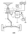
電動パワーステアリング装置の一般的な構成を図1に示して説明すると、ハンドル(ステアリングホイール)1のコラム軸(ステアリングシャフト)2は減速ギア3、ユニバーサルジョイント4a及び4b、ピニオンラック機構5、タイロッド6a,6bを経て、更にハブユニット7a,7bを介して操向車輪8L,8Rに連結されている。また、コラム軸2には、ハンドル1の操舵トルクを検出するトルクセンサ10が設けられており、ハンドル(ステアリングホイール)1の操舵力を補助するモータ20が減速ギア3を介してコラム軸2に連結されている。電動パワーステアリング装置を制御するコントロールユニット(ECU)30には、バッテリ13から電力が供給されると共に、イグニションキー11を経てイグニションキー信号が入力される。コントロールユニット30は、トルクセンサ10で検出された操舵トルクTsと車速センサ12で検出された車速Vsとに基づいてアシスト(操舵補助)指令の操舵補助指令値の演算を行い、操舵補助指令値に補償等を施した電圧制御値Vrefによってモータ20に供給する電流を制御する。なお、舵角センサ14は必須のものではなく、配設されていなくても良く、モータ20に連結された回転センサから得ることもできる。
コントロールユニット30には、車両の各種情報を授受するCAN(Controller Area Network)40が接続されており、車速VsはCAN40から受信することも可能である。また、コントロールユニット30には、CAN40以外の通信、アナログ/ディジタル信号、電波等を授受する非CAN41も接続可能である。
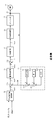
このような電動パワーステアリング装置において、コントロールユニット30は主としてCPU(MPUやMCU等を含む)で構成されるが、そのCPU内部においてプログラムで実行される一般的な機能を示すと、例えば図2に示されるような構成となっている。
図2を参照してコントロールユニット30の機能及び動作を説明すると、トルクセンサ10からの操舵トルクTs及び車速センサ12からの車速Vsは電流指令値演算部31に入力され、電流指令値演算部31は操舵トルクTs及び車速Vsに基づいてアシストマップ等を用いて電流指令値Iref1を演算する。演算された電流指令値Iref1は加算部32Aで、特性を改善するための補償部34からの補償信号CMと加算され、加算された電流指令値Iref2が電流制限部33で最大値を制限され、最大値を制限された電流指令値Irefmが減算部32Bに入力され、モータ電流検出値Imと減算される。
減算部32Bでの減算結果I(=Irefm-Im)はPI制御部35でPI(比例積分)制御され、PI制御された電圧制御値VrefがPWM制御部36に入力されてデューティを演算され、デューティを演算されたPWM信号でインバータ37を介してモータ20をPWM駆動する。モータ20のモータ電流値Imはモータ電流検出手段38で検出され、減算部32Bに入力されてフィードバックされる。
補償部34は、検出若しくは推定されたセルフアライニングトルク(SAT)34-3を加算部34-4で慣性補償値34-2と加算し、その加算結果に更に加算部34-5で収れん性制御値34-1を加算し、その加算結果を補償信号CMとして加算部32Aに入力し、特性改善する。
このような電動パワーステアリング装置において、近年駐車支援機能(パーキングアシスト)、障害物回避機能、レーンキープ機能等の自動操舵モードの機能を搭載し、自動操舵モードと手動操舵モードとを切替える車両が出現して来ており、駐車支援機能を搭載した車両にあってはカメラ(画像)や距離センサなどのデータを基に目標操舵角を設定し、目標操舵角に実操舵角を追従させる自動操舵制御が行われる。
従来周知の自動操舵モードと手動操舵モードの機能を有する電動パワーステアリング装置では、例えば駐車支援では、予め記憶した車両の移動距離と転舵角との関係に基づいてアクチュエータ(モータ)を制御することにより、バック駐車や縦列駐車を自動で行うようになっている。即ち、駐車支援装置は、アラウンドビューモニタや超音波センサ等の測位センサから駐車スペースを認識し、EPS側に舵角指令値(角度制御指令値)を出力する。EPSは、舵角指令値に追従するように実舵角を位置制御することによって、車両は駐車スペースへと誘導されていく。
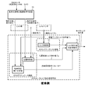
図3は、駐車支援モード機能を有する電動パワーステアリング装置の制御系を示しており、駐車支援等自動操舵指令装置50にはカメラ、測位センサ(超音波センサ等)から各種データが入力され、駐車支援用舵角指令値はCAN等を経てEPSアクチュエータ機能内の位置制御部(角度制御部)51に入力され、駐車支援実行指令はCAN等を経てEPSアクチュエータ機能内の駐車支援実行判定部52に入力される。駐車支援実行判定部52にはEPSセンサからの操舵トルクTsも入力されている。舵角センサ若しくは外部からの舵角信号である実舵角θrは位置制御部51に入力され、駐車支援実行判定部52の判定結果はトルク指令値徐変切替え部54に入力される。また、EPSセンサの操舵トルクTsは、EPSパワーアシスト機能内のトルク制御部53に入力され、トルク制御部53からの操舵アシストトルク指令値Tcがトルク指令値徐変切替え部54に入力される。位置制御部51からの位置制御トルク指令値Tpもトルク指令値徐変切替え部54に入力され、駐車支援実行判定部52の判定結果に従って操舵アシストトルク指令値Tcと位置制御トルク指令値Tpとが切替えられ、モータトルク指令値として出力され、電流制御系を介してモータが駆動制御される。
なお、位置制御部51は実際には速度制御も行うようになっており、舵角速度が入力される位置/速度制御部になっているが、ここでは説明の便宜上位置制御に限定している。
このように通常のパワーアシストはトルク制御系であるのに対し、駐車支援等の自動運転の場合は舵角等の角度(位置)制御系となる。トルク制御と角度制御を互いに切替える際、制御トルクの変動が生じ、スムーズに切替わらない問題や切替え時のトルク変動がトリガとなって、意図しないセルフステアが生じる問題がある。
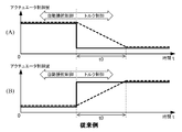
従来角度制御(自動操舵)からトルク制御(手動制御)への移行方法に関しては、例えば特許第3311277号公報(特許文献1)に開示されている自動操舵装置がある。特許文献1の自動操舵装置では、図4(A)の破線に示すように、自動操舵制御(角度制御)からトルク制御への移行に伴ってアクチュエータ(モータ)の制御量が減少する場合には、所定時間t0 が経過する間に、制御量を自動操舵制御時の値から、トルク制御時の値まで線形に減少させることにより、運転者がハンドルから受ける操舵反力が急激に変化しないようにする。また図4(B)の破線に示すように、自動操舵制御からトルク制御への移行に伴ってアクチュエータの制御量が増加する場合には,所定時間t0 が経過する間に、制御量を自動操舵制御時の値からトルク制御時の値まで線形に増加させることにより、運転者がハンドルから受ける操舵反力が急激に変化しないようにする。その結果、ハンドルが急激に軽くなって必要以上の転舵角が発生したり、ハンドルが急激に重くなって必要な転舵角が得られなくなったりすることを防止している。
しかしながら、特許文献1の自動操舵装置では、角度制御とトルク制御の指令値の差を全く考慮していないため、角度制御指令値とトルク制御指令値の差が大きい場合は、運転者に伝わるトルク変化が大きく、安全性を低下させたり、違和感を感じさせたりする問題がある。
本発明は上述のような事情よりなされたものであり、本発明の目的は、角度制御(自動操舵モード)からトルク制御(手動操舵モード)に制御方式を切替える徐変処理に際して、角度制御指令値とトルク制御指令値の指令値差に基づいて徐変時間を変更することにより、安全で違和感を低減した高性能な電動パワーステアリング装置を提供することにある。
本発明は、操舵トルクを検出するトルクセンサと、操舵を補助するアシストトルクを車両の操舵機構に付与するモータを制御するモータ制御装置とを有する電動パワーステアリング装置に関し、本発明の上記目的は、所定の切替え契機に従って、自動操舵モードの角度制御指令値に応じて制御する角度制御方式と、手動操舵モードのトルク制御指令値に応じて制御するトルク制御方式との間で前記モータの制御方式を切替える機能を具備し、前記角度制御方式から前記トルク制御方式に徐変で切替えるとき、前記角度制御指令値と前記トルク制御指令値の指令値差に応じて徐変時間を可変とすることにより達成される。
本発明の上記目的は、前記指令値差が、前記角度制御指令値と前記トルク制御指令値の差の絶対値であることにより、或いは前記所定の切替え契機が、自動操舵指令のON/OFFであることにより、或いは前記自動操舵指令のON/OFFが、駐車支援の指令、障害物回避の指令若しくはレーンキープの指令であることにより、或いは前記所定の切替え契機が、前記操舵トルクの内部判定によって与えられる切替え指令のON/OFFであることにより、或いは前記徐変時間が前記指令値差に応じて線形又は非線形に変化するようになっていることにより、或いは前記徐変を線形又は非線形で行うことにより、より効果的に達成される。
本発明に係る電動パワーステアリング装置によれば、自動操舵モードの角度制御(障害物回避、駐車支援等)から手動操舵モードのトルク制御にモータ出力制御方式を切替える徐変処理に際して、角度制御指令値とトルク制御指令値の指令値差に基づいて徐変時間を変更している。指令値差が大きいときに徐変時間を長く設定して、より徐々に切替える。このため、安全で、運転者に対する違和感を低減した高性能な電動パワーステアリング装置を提供することができる。
電動パワーステアリング装置における従来のモータ制御方式では、自動操舵モードの角度制御指令値と、手動操舵モードのトルク制御指令値との差の絶対値である指令値差を全く考慮していないため、指令値差が大きい場合は、運転者に伝わるトルク変化が大きく、安全性を低下させたり、運転者に違和感を感じさせたりする問題が生じている。このため、本発明では、自動操舵ON/OFFの切替え契機として、例えば車両障害物回避指令のON/OFF、駐車支援指令のON/OFF、操舵トルクの内部判定によって与えられる切替え指令のON/OFFが入力され、自動操舵モードの角度制御方式から手動操舵モードのトルク制御方式に切替えるとき、指令値差に応じて徐変時間を可変(指令値差が大きいときに徐変時間を長く)することにより、安全かつ違和感の抑制された操舵を実現している。
例えば障害物回避の自動操舵モードではカメラやレーダにより前方の障害物を認識し、操舵により障害物を回避する必要がある。電動パワーステアリング装置の制御は、通常はトルク制御で、障害物回避時は角度制御となるが、障害物回避から通常に戻すときに、指令値差に応じて徐変時間を可変する。
以下に、本発明の実施の形態を、図面を参照して詳細に説明する。本実施形態では、自動操舵モードとして障害物回避の例について説明するが、駐車支援やレーンキープ等でも同様である。
図5は本発明の構成例を示しており、操舵トルクTs及び車速Vsはトルク制御部110に入力され、トルク制御部110は操舵トルクTs及び車速Vsに基づいてトルク制御指令値TCを演算し、タイヤ転舵角指令値At及び実転舵角Arは角度制御部120に入力され、角度制御部120はタイヤ転舵角指令値At及び実転舵角Arに基づいて角度制御指令値ACを演算する。トルク制御部110からのトルク制御指令値TCは、切替え制御部100内の指令値差演算部102及び切替え部104に入力され、角度制御部120からの角度制御指令値ACは、切替え制御部100内の指令値差演算部102及び切替え部104に入力される。
また、切替え契機としての車両障害物回避信号Vf(正常時に論理“0”、回避時に論理“1”)は、切替え制御部100内の判定部101に入力され、判定部101は、車両障害物回避信号Vfが“0”から“1に変化したか、或いは”“1”から“0”に変化したかを判定する。判定部101は、車両障害物回避信号Vfが“0”から“1”に変化したと判定したときに判定信号DS2を出力し、判定信号DS2は切替え部104に入力される。また、判定部101は、車両障害物回避信号Vfが“1”から“0”に変化したと判定したときに判定信号DS1を出力し、判定信号DS1は指令値差演算部102に入力される。
指令値差演算部102に判定信号DS1が入力されると、指令値差演算部102はトルク制御指令値TCと角度制御指令値ACとの差の絶対値である指令値差CDを演算する。即ち、指令値差CDは下記数1で演算する。
(数1)
指令値差CD=|トルク制御指令値TC-角度制御指令値AC|
指令値差CDは徐変時間演算部103に入力され、徐変時間演算部103は、例えば図6の特性A,B,Cに示すような演算式で指令値差CDに応じて徐変時間Tjを演算する。即ち、徐変時間Tjは下記数2で演算する。
(数2)
徐変時間Tj=徐変時間変換係数×指令値差CD
特性Aは線形演算の例であり、特性B及びCは非線形演算の例である。徐変時間演算部103で演算された徐変時間Tjは切替え部104に入力され、切替え部104は例えば図7に示すような徐変特性(徐変時間Tj)で、角度制御からトルク制御に切替える。即ち、時点t11までは角度制御(100%)であり、時点t11に車両障害物回避信号Vfが“1”から“0”に変化したとき、切替え部104は徐変時間Tjに従って時点t12まで線形特性でトルク制御に切替える。時点t12以降、トルク制御(100%)である。
(数1)
指令値差CD=|トルク制御指令値TC-角度制御指令値AC|
指令値差CDは徐変時間演算部103に入力され、徐変時間演算部103は、例えば図6の特性A,B,Cに示すような演算式で指令値差CDに応じて徐変時間Tjを演算する。即ち、徐変時間Tjは下記数2で演算する。
(数2)
徐変時間Tj=徐変時間変換係数×指令値差CD
特性Aは線形演算の例であり、特性B及びCは非線形演算の例である。徐変時間演算部103で演算された徐変時間Tjは切替え部104に入力され、切替え部104は例えば図7に示すような徐変特性(徐変時間Tj)で、角度制御からトルク制御に切替える。即ち、時点t11までは角度制御(100%)であり、時点t11に車両障害物回避信号Vfが“1”から“0”に変化したとき、切替え部104は徐変時間Tjに従って時点t12まで線形特性でトルク制御に切替える。時点t12以降、トルク制御(100%)である。
切替え部104の出力はモータ指令値MCとして出力され、モータ指令値MCは電流制御系130に入力され、電流制御系130を経てアシスト用のモータ131が駆動制御される。
また、判定部101が、車両障害物回避信号Vfが“1”から“0に変化したと判定すると、判定部101は判定信号DS2を出力し、判定信号DS2は切替え部104に入力される。その結果、切替え部104は図8に示すようなステップ特性で、つまり時点t1に判定信号DS2が入力されると、瞬時にトルク制御(100%)から角度制御(100%)に切替えられる。
このような構成において、その動作例を図9のフローチャートを参照して説明する。
先ず、判定部101は車両障害物回避信号Vfが“0”から“1に変化したか否かを判定し(ステップS1)、車両障害物回避信号Vfが“0”から“1に変化した場合には、判定部101は判定信号DS2を出力し、これにより切替え部104は図8の特性に従って、トルク制御から角度制御に切替える(ステップS2)。これにより、角度制御が実施される。
また、上記ステップS1において、車両障害物回避信号Vfが“0”から“1に変化したと判定されない場合には、判定部101は、車両障害物回避信号Vfが“1”から“0に変化したか否かを判定する(ステップS10)。そして、車両障害物回避信号Vfが“1”から“0に変化したと判定した場合には、判定部101は判定信号DS1を出力し、判定信号DS1は指令値差演算部102に入力される。これにより、指令値差演算部102は、トルク制御指令値TCと角度制御指令値ACの差の絶対値である指令値差CDを演算する(ステップS11)。演算された指令値差CDは徐変時間演算部103に入力され、徐変時間演算部103は図6で示すような特性で、つまり指令値差CDが大きくなるに従って大きくなる徐変時間Tjが演算される(ステップS12)。徐変時間Tjは切替え部104に入力され、切替え部104は徐変時間Tjに従って、図7で示すような徐変処理で角度制御からトルク制御に徐々に切替える(ステップS13)。
一方、上記ステップS10において、車両障害物回避信号Vfが“1”から“0に変化しない場合には、現在の制御を維持する(ステップS20)。
なお、上述では、車両障害物回避信号Vfが正常時に論理“0”、回避時に論理“1”としているが、正常時に論理“1”、回避時に論理“0”とし、逆の判定をするようにしても良い。また、徐変処理の特性も、図10に示すように、非線形な徐変特性であっても良い。
1 ハンドル(ステアリングホイール)
2 コラム軸(ステアリングシャフト、ハンドル軸)
10 トルクセンサ
12 車速センサ
13 バッテリ
20 モータ
21 モータ駆動部
30 コントロールユニット(ECU)
40 CAN
41 非CAN
50 駐車支援等自動操舵指令装置
51 位置制御部
52 駐車支援実行判定部
53 トルク制御部
54 トルク指令値徐変切替え部
100 切替え制御部
101 判定部
102 指令値差演算部
103 徐変時間演算部
104 切替え部
110 トルク制御部
120 角度制御部
130 電流制御系
131 モータ
2 コラム軸(ステアリングシャフト、ハンドル軸)
10 トルクセンサ
12 車速センサ
13 バッテリ
20 モータ
21 モータ駆動部
30 コントロールユニット(ECU)
40 CAN
41 非CAN
50 駐車支援等自動操舵指令装置
51 位置制御部
52 駐車支援実行判定部
53 トルク制御部
54 トルク指令値徐変切替え部
100 切替え制御部
101 判定部
102 指令値差演算部
103 徐変時間演算部
104 切替え部
110 トルク制御部
120 角度制御部
130 電流制御系
131 モータ
Claims (9)
- 操舵トルクを検出するトルクセンサと、操舵を補助するアシストトルクを車両の操舵機構に付与するモータを制御するモータ制御装置とを有する電動パワーステアリング装置において、
所定の切替え契機に従って、自動操舵モードの角度制御指令値に応じて制御する角度制御方式と、手動操舵モードのトルク制御指令値に応じて制御するトルク制御方式との間で前記モータの制御方式を切替える機能を具備し、
前記角度制御方式から前記トルク制御方式に徐変で切替えるとき、前記角度制御指令値と前記トルク制御指令値の指令値差に応じて徐変時間を可変としたことを特徴とする電動パワーステアリング装置。 - 前記指令値差が、前記角度制御指令値と前記トルク制御指令値の差の絶対値である請求項1に記載の電動パワーステアリング装置。
- 前記所定の切替え契機が、自動操舵指令のON/OFFである請求項1又は2に記載の電動パワーステアリング装置。
- 前記自動操舵指令のON/OFFが、駐車支援の指令、障害物回避の指令若しくはレーンキープの指令である請求項3に記載の電動パワーステアリング装置。
- 前記所定の切替え契機が、前記操舵トルクの内部判定によって与えられる切替え指令のON/OFFである請求項1又は2に記載の電動パワーステアリング装置。
- 前記徐変時間が前記指令値差に応じて線形に変化するようになっている請求項1乃至5のいずれかに記載の電動パワーステアリング装置。
- 前記徐変時間が前記指令値差に応じて非線形に変化するようになっている請求項1乃至5のいずれかに記載の電動パワーステアリング装置。
- 前記徐変を線形で行う請求項1乃至7のいずれかに記載の電動パワーステアリング装置。
- 前記徐変を非線形で行う請求項1乃至7のいずれかに記載の電動パワーステアリング装置。
Priority Applications (4)
| Application Number | Priority Date | Filing Date | Title |
|---|---|---|---|
| EP16807545.5A EP3266678B1 (en) | 2015-06-12 | 2016-06-09 | Electric power steering device |
| JP2017523687A JP6237958B2 (ja) | 2015-06-12 | 2016-06-09 | 電動パワーステアリング装置 |
| CN201680032746.8A CN107848570B (zh) | 2015-06-12 | 2016-06-09 | 电动助力转向装置 |
| US15/571,578 US10059369B2 (en) | 2015-06-12 | 2016-06-09 | Electric power steering apparatus |
Applications Claiming Priority (2)
| Application Number | Priority Date | Filing Date | Title |
|---|---|---|---|
| JP2015119727 | 2015-06-12 | ||
| JP2015-119727 | 2015-06-12 |
Publications (1)
| Publication Number | Publication Date |
|---|---|
| WO2016199839A1 true WO2016199839A1 (ja) | 2016-12-15 |
Family
ID=57503623
Family Applications (1)
| Application Number | Title | Priority Date | Filing Date |
|---|---|---|---|
| PCT/JP2016/067179 Ceased WO2016199839A1 (ja) | 2015-06-12 | 2016-06-09 | 電動パワーステアリング装置 |
Country Status (5)
| Country | Link |
|---|---|
| US (1) | US10059369B2 (ja) |
| EP (1) | EP3266678B1 (ja) |
| JP (1) | JP6237958B2 (ja) |
| CN (1) | CN107848570B (ja) |
| WO (1) | WO2016199839A1 (ja) |
Cited By (7)
| Publication number | Priority date | Publication date | Assignee | Title |
|---|---|---|---|---|
| EP3495245A1 (en) * | 2017-11-29 | 2019-06-12 | Jtekt Corporation | Vehicle steering system |
| JP2020083262A (ja) * | 2018-11-30 | 2020-06-04 | ダイハツ工業株式会社 | 車両制御システム |
| WO2020184853A1 (ko) * | 2019-03-11 | 2020-09-17 | 주식회사 만도 | 전동 파워스티어링 시스템의 오버레이 제어 장치 및 그 방법 |
| JPWO2019107438A1 (ja) * | 2017-11-30 | 2020-11-26 | 株式会社ジェイテクト | 車両用操舵装置 |
| KR20210128705A (ko) * | 2020-04-17 | 2021-10-27 | 현대모비스 주식회사 | 전동식 조향시스템의 제어 장치 및 방법 |
| KR20210131495A (ko) * | 2020-04-23 | 2021-11-03 | 현대모비스 주식회사 | 전동식 파워 스티어링 시스템의 제어 장치 및 방법 |
| WO2023112133A1 (ja) | 2021-12-14 | 2023-06-22 | 三菱電機株式会社 | 電動パワーステアリング装置 |
Families Citing this family (8)
| Publication number | Priority date | Publication date | Assignee | Title |
|---|---|---|---|---|
| WO2016088704A1 (ja) * | 2014-12-02 | 2016-06-09 | 日本精工株式会社 | 電動パワーステアリング装置 |
| KR102335985B1 (ko) * | 2017-07-04 | 2021-12-07 | 현대자동차주식회사 | 조향각 제어 장치, 그를 포함한 차로 추종 보조 시스템 및 그 방법 |
| JP7129003B2 (ja) * | 2018-09-21 | 2022-09-01 | 株式会社ジェイテクト | モータ制御装置 |
| JP2020082915A (ja) * | 2018-11-20 | 2020-06-04 | 株式会社ジェイテクト | 操舵装置および操舵装置におけるモータ制御方法 |
| CN111547050B (zh) * | 2019-01-24 | 2021-07-16 | 北汽福田汽车股份有限公司 | 横向控制模式切换的方法、装置、系统和汽车 |
| JP2020147213A (ja) * | 2019-03-14 | 2020-09-17 | トヨタ自動車株式会社 | 自動運転システムの制御装置と該装置による制御方法 |
| US11066025B2 (en) * | 2019-03-27 | 2021-07-20 | Jack Chen | Electric vehicle drive system and operation method of the same |
| JP7205373B2 (ja) * | 2019-05-07 | 2023-01-17 | 株式会社デンソー | 回転電機制御装置 |
Citations (4)
| Publication number | Priority date | Publication date | Assignee | Title |
|---|---|---|---|---|
| JPH05170118A (ja) * | 1991-12-25 | 1993-07-09 | Aisin Seiki Co Ltd | 車輌の自動操舵制御装置 |
| JPH10309961A (ja) * | 1997-05-12 | 1998-11-24 | Toyota Motor Corp | 自動走行車両制御装置 |
| JPH1178940A (ja) * | 1997-09-05 | 1999-03-23 | Honda Motor Co Ltd | 車両の自動操舵装置 |
| JPH11286280A (ja) * | 1998-04-03 | 1999-10-19 | Mitsubishi Electric Corp | 車両の自動走行制御装置 |
Family Cites Families (4)
| Publication number | Priority date | Publication date | Assignee | Title |
|---|---|---|---|---|
| JP4057955B2 (ja) | 2003-05-28 | 2008-03-05 | 本田技研工業株式会社 | 車両の自動操舵装置 |
| JP4816248B2 (ja) * | 2006-05-23 | 2011-11-16 | 日産自動車株式会社 | 車両用運転操作補助装置 |
| JP4287452B2 (ja) * | 2006-09-12 | 2009-07-01 | 本田技研工業株式会社 | 車両の自動操舵装置 |
| CN104684792B (zh) * | 2013-02-07 | 2017-03-15 | 日本精工株式会社 | 电动助力转向装置 |
-
2016
- 2016-06-09 WO PCT/JP2016/067179 patent/WO2016199839A1/ja not_active Ceased
- 2016-06-09 JP JP2017523687A patent/JP6237958B2/ja not_active Expired - Fee Related
- 2016-06-09 US US15/571,578 patent/US10059369B2/en not_active Expired - Fee Related
- 2016-06-09 CN CN201680032746.8A patent/CN107848570B/zh active Active
- 2016-06-09 EP EP16807545.5A patent/EP3266678B1/en active Active
Patent Citations (4)
| Publication number | Priority date | Publication date | Assignee | Title |
|---|---|---|---|---|
| JPH05170118A (ja) * | 1991-12-25 | 1993-07-09 | Aisin Seiki Co Ltd | 車輌の自動操舵制御装置 |
| JPH10309961A (ja) * | 1997-05-12 | 1998-11-24 | Toyota Motor Corp | 自動走行車両制御装置 |
| JPH1178940A (ja) * | 1997-09-05 | 1999-03-23 | Honda Motor Co Ltd | 車両の自動操舵装置 |
| JPH11286280A (ja) * | 1998-04-03 | 1999-10-19 | Mitsubishi Electric Corp | 車両の自動走行制御装置 |
Cited By (14)
| Publication number | Priority date | Publication date | Assignee | Title |
|---|---|---|---|---|
| EP3495245A1 (en) * | 2017-11-29 | 2019-06-12 | Jtekt Corporation | Vehicle steering system |
| JP7236037B2 (ja) | 2017-11-30 | 2023-03-09 | 株式会社ジェイテクト | 車両用操舵装置 |
| JPWO2019107438A1 (ja) * | 2017-11-30 | 2020-11-26 | 株式会社ジェイテクト | 車両用操舵装置 |
| JPWO2019107437A1 (ja) * | 2017-11-30 | 2020-12-10 | 株式会社ジェイテクト | 車両用操舵装置 |
| JP7236038B2 (ja) | 2017-11-30 | 2023-03-09 | 株式会社ジェイテクト | 車両用操舵装置 |
| JP2020083262A (ja) * | 2018-11-30 | 2020-06-04 | ダイハツ工業株式会社 | 車両制御システム |
| JP7175577B2 (ja) | 2018-11-30 | 2022-11-21 | ダイハツ工業株式会社 | 車両制御システム |
| WO2020184853A1 (ko) * | 2019-03-11 | 2020-09-17 | 주식회사 만도 | 전동 파워스티어링 시스템의 오버레이 제어 장치 및 그 방법 |
| KR20210128705A (ko) * | 2020-04-17 | 2021-10-27 | 현대모비스 주식회사 | 전동식 조향시스템의 제어 장치 및 방법 |
| KR102718298B1 (ko) | 2020-04-17 | 2024-10-17 | 현대모비스 주식회사 | 전동식 조향시스템의 제어 장치 및 방법 |
| KR20210131495A (ko) * | 2020-04-23 | 2021-11-03 | 현대모비스 주식회사 | 전동식 파워 스티어링 시스템의 제어 장치 및 방법 |
| US11554808B2 (en) | 2020-04-23 | 2023-01-17 | Hyundai Mobis Co., Ltd. | Apparatus and method for controlling motor-driven power steering system |
| KR102341112B1 (ko) * | 2020-04-23 | 2021-12-21 | 현대모비스 주식회사 | 전동식 파워 스티어링 시스템의 제어 장치 및 방법 |
| WO2023112133A1 (ja) | 2021-12-14 | 2023-06-22 | 三菱電機株式会社 | 電動パワーステアリング装置 |
Also Published As
| Publication number | Publication date |
|---|---|
| CN107848570A (zh) | 2018-03-27 |
| EP3266678A1 (en) | 2018-01-10 |
| JPWO2016199839A1 (ja) | 2017-12-14 |
| CN107848570B (zh) | 2019-03-26 |
| US20180154929A1 (en) | 2018-06-07 |
| JP6237958B2 (ja) | 2017-11-29 |
| EP3266678A4 (en) | 2018-10-10 |
| US10059369B2 (en) | 2018-08-28 |
| EP3266678B1 (en) | 2019-10-23 |
Similar Documents
| Publication | Publication Date | Title |
|---|---|---|
| JP6237958B2 (ja) | 電動パワーステアリング装置 | |
| JP6519695B2 (ja) | 電動パワーステアリング装置 | |
| JP6365711B2 (ja) | 電動パワーステアリング装置 | |
| JP6477938B2 (ja) | 電動パワーステアリング装置 | |
| JP6477995B1 (ja) | 電動パワーステアリング装置 | |
| JP6098764B2 (ja) | 電動パワーステアリング装置 | |
| JP5967336B2 (ja) | 電動パワーステアリング装置 | |
| US9718492B2 (en) | Electric power steering apparatus | |
| JP6565847B2 (ja) | 電動パワーステアリング装置 | |
| CN112585050A (zh) | 用于车辆转向的致动器控制装置 | |
| JP6760113B2 (ja) | 電動パワーステアリング装置 | |
| JP2008290525A (ja) | 電動パワーステアリング装置の制御装置 |
Legal Events
| Date | Code | Title | Description |
|---|---|---|---|
| 121 | Ep: the epo has been informed by wipo that ep was designated in this application |
Ref document number: 16807545 Country of ref document: EP Kind code of ref document: A1 |
|
| ENP | Entry into the national phase |
Ref document number: 2017523687 Country of ref document: JP Kind code of ref document: A |
|
| WWE | Wipo information: entry into national phase |
Ref document number: 15571578 Country of ref document: US |
|
| NENP | Non-entry into the national phase |
Ref country code: DE |