WO2016199649A1 - 巻締め装置 - Google Patents
巻締め装置 Download PDFInfo
- Publication number
- WO2016199649A1 WO2016199649A1 PCT/JP2016/066272 JP2016066272W WO2016199649A1 WO 2016199649 A1 WO2016199649 A1 WO 2016199649A1 JP 2016066272 W JP2016066272 W JP 2016066272W WO 2016199649 A1 WO2016199649 A1 WO 2016199649A1
- Authority
- WO
- WIPO (PCT)
- Prior art keywords
- lid
- seaming
- unit
- chuck
- turret
- Prior art date
Links
Images


Classifications
-
- B—PERFORMING OPERATIONS; TRANSPORTING
- B21—MECHANICAL METAL-WORKING WITHOUT ESSENTIALLY REMOVING MATERIAL; PUNCHING METAL
- B21D—WORKING OR PROCESSING OF SHEET METAL OR METAL TUBES, RODS OR PROFILES WITHOUT ESSENTIALLY REMOVING MATERIAL; PUNCHING METAL
- B21D51/00—Making hollow objects
- B21D51/16—Making hollow objects characterised by the use of the objects
- B21D51/26—Making hollow objects characterised by the use of the objects cans or tins; Closing same in a permanent manner
- B21D51/30—Folding the circumferential seam
Definitions
- the present invention relates to a can mounting unit for mounting a can, a chuck unit provided facing the can mounting unit, and a winding device including a seaming roll for winding a lid on the can.
- a tightening device provided with a can mounting unit for mounting a can filled with beverages, a chuck unit provided facing the can mounting unit, and a seaming roll for winding a lid around the can
- a known winding device includes a seaming turret (1) that performs a winding process of a can and a lid, and a carry-in conveyor (supply) that supplies the can before the winding to the seaming turret.
- lid transport turret (supply turret 3) of the lid supply unit for supplying the lid
- discharge turret discharge turret 5 for unloading the rolled can from the seaming turret, and further removing the can from the discharge turret
- a carry-out conveyor (discharge conveyor 8) for carrying out to the outside is provided.
- the seaming turret, discharge turret, and lid transport turret are provided with pockets (fitting recesses 2, 4, 6) for individually accommodating and transporting cans and lids on the outer periphery.
- a can placing unit lifter 17 for placing a can
- a chuck unit suaming chuck device 10
- a lid as a can Seaming rolls (18, 19) for tightening are provided.
- each turret and each conveyor are matched with a gear or the like, and the operations of the can placing unit, the chuck unit and the seaming unit arranged in each pocket can be controlled by the gear and cam.
- the gear and cam By interlocking with the rotation of the seaming turret by a mechanism or the like, it is possible to continuously wind and tighten the can and the lid conveyed at high speed.
- such a known tightening device has a can mounting unit (lifter) provided in each pocket of the seaming turret and a knockout pad
- the pad is linked to the rotation of the seaming turret by a cam mechanism. Then go up and down.
- the can supplied to each pocket of the seaming turret raises the can mounting unit (lifter), clamps the can and the lid with the chuck, and tightens the lid.
- the can's posture when transferring the can from the carry-in conveyor to the can placing unit (lifter) of the seaming turret for winding tightening becomes unstable and hits the guide of the can or the pocket of the seaming turret. Occurs and buckles during winding due to the dent.
- the cans are conveyed on the carry-in conveyor with slight shaking, and if the can is raised at a high speed by the can placing unit, its posture becomes unstable and decentered. appear.
- the present invention solves the above-mentioned problems, stabilizes the can posture during transfer when feeding cans from a carry-in conveyor, and is caused by a recess by a guide guide or seaming turret pocket. It is an object of the present invention to provide a winding device capable of preventing buckling during winding and improving the winding accuracy.
- a winding and tightening device includes a can mounting unit for mounting a can, a chuck unit provided facing the can mounting unit, and a seaming unit for winding a lid to the can.
- the can mounting unit has a pressing mechanism that elastically presses the plate on which the can is mounted, and the chuck unit and the seaming unit are configured to be movable up and down.
- the can mounting unit has a pressing mechanism that elastically presses the plate on which the can is mounted upward, and the chuck unit and the seaming unit can be moved up and down.
- the can mounting unit has a pressing mechanism that elastically presses the plate on which the can is mounted upward, and the chuck unit and the seaming unit can be moved up and down.
- the chuck unit and the seaming unit are integrally formed so as to move up and down by a single cam mechanism, so that the frictional heat between the rotating shaft and the oil seal or the like is generated. Changes in the positions of the chuck and the seaming roll due to expansion can be prevented, and maintenance can be facilitated.
- the rotation of the plate of the can mounting unit and the chuck of the chuck unit and the winding operation of the seaming roll of the seaming unit are performed by independently controlled drive sources. As a result, the start and acceleration timing of the plate and chuck, and the timing of the tightening operation can be optimally adjusted individually without stopping the operation by controlling the respective drive sources, so adjustment work can be done in a short time. Can be easily performed.
- the winding and tightening device includes a carry-in conveyor that supplies a can to the seaming turret, a lid supply unit that supplies a lid, and a lid supply turret.
- the conveyor, lid supply device, and lid transport turret each have a drive source that is controlled independently, so that the operation timing according to the size, weight, winding dimensions, etc. of the can can be optimized individually without stopping the operation. Therefore, the adjustment work can be easily performed in a short time.
- the drive source is a servo motor, adjustment can be performed with an electric control command, feedback control can be performed, and adjustment work can be easily performed in a short time. Can be performed.
- a chuck unit that eliminates the need for raising and lowering the plate of the can mounting unit by supplying a can on which the lid is mounted to the seaming turret by a carry-in conveyor. Tightening is performed by the seaming unit.
- the chuck unit is easy to correct the position of the lid by making only the chuck abut the lid, lowering the chuck, centering the lid, and pressing the lid. The buckling of the can can be prevented without applying an unbalanced load, and the can can be made thinner.
- the chuck has the lid adsorbing means, so that the lid is adsorbed to the chuck and the fitting force is increased, thereby preventing the winding failure due to the slip. It is possible to reduce the axial load applied to the can, preventing buckling of the can and reducing the thickness.
- the lid is attracted by the chuck's lid adsorbing means, the lid is centered, and after the adsorption, the chuck is lowered and the lid is placed on the can, thereby eliminating the need for raising and lowering the plate of the can placement unit. Then, the tightening is performed by the chuck unit and the seaming unit.
- the seaming turret has a detection unit that detects the position of the pocket, and the conveyance path of the carry-in conveyor has a pitch sensor that detects the attachment of the carry-in conveyor.
- the chuck unit includes the rotary blade pump that forcibly discharges the lubricating oil, thereby minimizing the accumulation of the lubricating oil at the upper part of the oil seal, and from the oil seal caused by the rotation of the chuck.
- the pressing mechanism of the can mounting unit is configured to operate with fluid pressure, so adjustment is extremely easy and during operation.
- the height of the can decreases slightly during winding, even if the error in the actual can height reduction is absorbed by the pressing mechanism, the axial load does not change and the winding accuracy is improved. It is possible to improve the speed of the winding process.
- the diaphragm for sealing the fluid pressure is provided, a sliding seal member becomes unnecessary, and there is no seal resistance when moving up and down, and the plate can be moved up and down smoothly. .
- FIG. 9 is a cross-sectional view of FIG. 8.
- DESCRIPTION OF SYMBOLS 100 Tightening device 101 ... Seaming turret 102 ... Carry-in conveyor 103 ... Attachment 105 ... Lid supply device 106 ... Lid conveyance turret 107 ... Discharge turret 108 ... Unloading Conveyor 110 ... Can mounting unit 111 ... Pressing mechanism 112 ... Plate 113 ... Cylinder space 114 ... Piston 118 ... Diaphragm 120 ... Chuck unit 121 ... Chuck 122 ...
- a winding device 100 includes a seaming turret 101 that performs a winding process of a can C and a lid F, and a lid F placed on the seaming turret 101.
- a carry-in conveyor 102 that supplies cans C
- a lid supply unit 104 that includes a lid supply device 105 that supplies lids F and a lid transport turret 106, and a discharge turret 107 that carries the rolled can CM out of the seaming turret 101
- the can CM is further provided with a carry-out conveyor 108 for carrying out the can CM from the discharge turret 107 to the outside.
- the seaming turret 101, the discharge turret 107, and the lid transport turret 106 are provided with pockets P for individually accommodating and transporting cans C, CM, and lid F on the outer periphery, respectively. And an attachment 103 that is individually engaged and conveyed.
- the rotational speed of the seaming turret 101, the discharge turret 107 and the lid transport turret 106, the moving speed of the attachment 103 of the carry-in conveyor 102, and the interlocking timing of each pocket P and attachment 103 are the can C, CM between each turret and conveyor.
- the lid F is designed to be adjustable so that it can be delivered smoothly.
- the seaming turret 101 that performs the winding process of the can C and the lid F is opposed to the can placement unit 110 that places the can C in each pocket P, and the can placement unit 110.
- the seaming turret 101 is rotationally driven by a driving motor 151 of the seaming turret, and is configured to be able to detect the pocket position from the rotational phase by the pocket position detection encoder 155.
- a pitch sensor S composed of a photoelectric tube, a proximity switch, a laser, and the like for detecting the position of the attachment 103 of the carry-in conveyor 102 is provided on the carry path of the carry-in conveyor 102, and the seaming turret 101 is output by the output of the pitch sensor S.
- the position of the attachment 103 with respect to the pocket P of the lid transport turret 106 is controlled.
- the lid supply device 105, the lid transport turret 106, and the carry-in conveyor 102 are driven by a drive motor 153 of the lid feed device 105, a drive motor 152 of the lid feed turret 106, and a drive motor 154 of the carry-in conveyor 102, respectively. Driven.
- Servo motors are used for each motor, and the speed and timing can be adjusted individually, and the speed and timing of the seaming turret 101 can be changed according to the output of the pocket position detection encoder 155. It is configured.
- the lid supply device 105, the lid transport turret 106, and the carry-in conveyor 102 are driven by independently controlled drive sources, so that the operation timing according to the dimensions, weight, winding dimensions, etc. of the can Can be optimally adjusted individually without stopping operation, and adjustment work can be easily performed in a short time.
- the drive source is a servo motor, the adjustment can be performed with an electric control command, the feedback control can be performed, and the adjustment work can be easily performed in a short time.
- the transmission mechanism is mechanically connected from the drive motor 151 of the seaming turret 101.
- An appropriate drive source may be used such as driving via If the design is such that the speed and timing can be easily adjusted in terms of accuracy and speed, the lid feeding device 105, the lid transport turret 106, and the carry-in conveyor 102 can also be driven from the drive motor 151 of the seaming turret 101.
- An appropriate drive source may be used, such as mechanically driving through a transmission mechanism.
- the can mounting unit 110 includes a plate 112 on which the can C is mounted, and a pressing mechanism 111 that elastically presses the plate 112 upward such as a spring or compressed air. Further, the can mounting unit 110 is configured not to move up and down other than up and down movement of the plate 112 by the pressing mechanism 111.
- the chuck unit 120 moves up and down by a vertical movement mechanism 122 of the chuck unit 120 including a vertical movement cam 123 and a vertical movement cam follower 124.
- the vertical movement cam 123 of the chuck unit 120 is fixedly provided.
- the vertical movement cam follower 124 of the chuck unit 120 moves following the cam profile, and the chuck 121 of the chuck unit 120 is moved. Moves up and down depending on the position.
- the width (thickness) of the gears attached to the chuck unit 120 and the drive motor 156 of the chuck 121 described later is appropriately set, and the rotation of the chuck 121 by the drive motor 156 in the vertical movement of the chuck unit 120 is controlled. .
- the above-described rotation control may be appropriately adopted or added.
- the seaming roll 131 moves up and down by the vertical movement mechanism 133 of the seaming unit 130 including the vertical movement cam 134 and the vertical movement cam follower 135.
- the vertical movement cam 134 of the seaming unit 130 is fixedly provided.
- the vertical movement cam follower 135 of the seaming unit 130 moves in accordance with the cam profile. Moves up and down depending on the position.
- the seaming unit 130 includes a spline K above the roll swing shaft 132 to enable expansion and contraction and rotation of the roll swing shaft 132, and the vertical movement of the seaming roll 131 by the vertical movement mechanism 133 described above, A seaming roll 131 is tightened and pressed by a drive motor 158 of a roll swing shaft 132, which will be described later.
- the means for enabling the seaming roll 131 to be moved up and down, wound and pressed is not limited to the spline K or the like of the roll rocking shaft 132, and may be appropriately adopted and added.
- the can mounting unit 110 has the pressing mechanism 111 that elastically presses the plate 112 on which the can is mounted, and the chuck unit 120 and the seaming unit 130 can be moved up and down. Since it is not necessary to raise and lower the plate 112 of the can placement unit 110 in a rotated state, the can C does not move up and down when the can is transferred from the carry-in conveyor 102 to the can placement unit 110, and the guide or A recess due to the pocket P of the seaming turret 101 and buckling at the time of winding due to the recess can be prevented, and the tightening accuracy can be improved.
- the drive source for the rotation of the plate 112 of the can mounting unit 110 and the chuck 121 of the chuck unit 120 is a servo motor that is controlled independently of each other.
- the drive motor 157 and the drive motor 156 of the chuck 121 are used as drive sources.
- the rotation start and acceleration timing of the plate 112 and the chuck 121 can be controlled independently, and can be optimally adjusted individually without stopping the operation with an operation panel, etc. It is possible to easily carry out, and it is possible to cope with fluctuations during operation.
- the rotation of the plate 112 and the chuck 121 is controlled, and the rotation of the plate 112 and the chuck 121 is stopped when the rotating chuck 121 is fitted to the lid placed on the can by controlling the timing of rotation and acceleration.
- the deviation of the rotation center can be reduced to prevent the can from being dented or damaged due to contact with the guide member or the like, and the centering performance of the lid by the chuck 121 can be improved.
- the drive source of the roll rocking shaft 132 of the seaming unit 130 is the drive motor 158 of the roll rocking shaft 132 configured by an independently controlled servo motor, so that the seaming roll 131 is driven.
- the timing of the tightening operation and the amount of pressing can be controlled independently and can be optimally adjusted individually without stopping the operation with an operation panel, etc., making adjustment work easy and quick. It is possible to cope with fluctuations in the medium.
- the rotation of the plate 112 and the chuck 121 and the drive source of the roll swing shaft 132 are servo motors, so that adjustment can be performed with an electrical control command and feedback control is also possible. Further, the adjustment work can be easily performed in a short time.
- the chuck unit 120 includes a chuck 121 that holds the lid F, and the chuck 121 is lowered so that the chuck outer peripheral portion 126 is placed on the can C supplied to the seaming turret 101.
- the chuck 121 performs centering of the lid F placed on the can C and presses the lid F, thereby facilitating the correction of the position of the lid F and preventing buckling of the can without applying an offset load.
- the can can be made thinner.
- the negative pressure suction hole 125 is formed in the chuck 121, and the centering is performed by adsorbing the lid F by the chuck 121.
- the speed and timing of the carry-in conveyor 102 and the lid transport turret 106 are matched to the speed and timing of the seaming turret 101 so that the centers of the can C and the lid F coincide at the junction G. Have been adjusted.
- the lid transport turret 106 is arranged so that the position Gb for sucking the lid F to the chuck 121 at a negative pressure is located upstream of the normal junction G.
- the lid F is sucked negatively by the chuck 121 whose rotation is controlled by a drive motor (servo motor) 156 to perform centering of the lid. Is called.
- a drive motor servo motor
- the lid F is lowered and placed on the can C, so that the plate 112 of the can placement unit 110 does not need to be lifted and lowered by the chuck unit 120 and the seaming unit 130. Is done.
- the chuck F is negatively sucked by the chuck 121 to perform the centering, so that the chuck outer peripheral portion 126 is fitted to the lid F, and the chuck 121 and the lid F are attracted in advance to increase the fitting force.
- winding failure due to slip is prevented.
- the axial load applied to the can C can be reduced, the buckling of the can C can be prevented, and the thickness can be reduced.
- the lid F is reliably centered by suction by the chuck 121, so that buckling due to an uneven load is prevented.
- the can C before the lid F is wound is engaged with each attachment 103 of the carry-in conveyor 102 and conveyed to the seaming turret 101.
- the lids F are cut out one by one from the lid supply device 105 and transferred to the respective pockets P of the lid transport turret 106, and are directed upward of the can C by the rotation of the lid transport turret 106 (see FIG. 1).
- the speed and timing of the carry-in conveyor 102 and the lid transport turret 106 are adjusted according to the speed and timing of the seaming turret 101 so that the centers of the can C and the lid F coincide at a predetermined position on the carry-in conveyor 102.
- the lid F falls toward the can C at a predetermined position, and the lid F is placed on the can C on the carry-in conveyor 102.
- the can C on which the lid F is placed is transferred from the carry-in conveyor 102 to the seaming turret 101, and the can placing unit whose rotation is controlled by the drive motor (servo motor) 157 of the can placing unit 110. 110 is placed on the plate 112.
- the chuck unit 120 whose rotation is controlled by the drive motor (servo motor) 156 is lowered by the vertical movement mechanism 122, and the chuck 121 of the chuck unit 120 is fitted to the lid F.
- the can C fitted with the lid F is sandwiched between the plate 112 and the chuck 121 with a certain axial load necessary for winding and tightening against the pressing force of the pressing mechanism 111 of the can mounting unit 110, and the chuck
- the centering of the lid F by 121 is performed, and the can C fitted at the same time is also centered.
- the centering of the lid F by the chuck 121 and the placement of the lid F on the can C are performed by forming the negative pressure suction hole 125 of the suction means in the chuck 121 and sucking the lid F to the centering.
- the chuck 121 may be lowered to place the lid F on the can C.
- the seaming turret 101 is further rotated, and before the sandwiched lid F and can C reach the winding tightening section E shown in FIG.
- the seaming unit 130 is moved down by the vertical movement mechanism 133 so that the seaming roll 131 is positioned at the tightening portion of the can C fitted with the lid F, and the seaming unit 130 is passing through the winding section E.
- the roll rocking shaft 132 is actuated by a drive motor (servo motor) 158, and the seaming roll 131 is pressed from the side to be tightened.
- a drive motor (servo motor) 158
- the seaming roll 131 is pressed from the side to be tightened.
- the roll swinging shaft 132 is actually provided with two seaming rolls 131 for primary winding and secondary winding. While passing through the section E, the pressing is sequentially performed to complete the tightening.
- the can CM for which the winding has been completed is transferred from the seaming turret 101 to the discharge turret 107, and further transferred from the discharge turret 107 to the carry-out conveyor 108, and is carried out to the next process such as inspection and packing.
- FIG. 7 shows another embodiment of the chuck unit and the seaming unit in the tightening device of the present invention.
- the chuck unit 120b and the seaming unit 130b are integrally formed by a housing 136, and the vertical movement cam 144 and the vertical movement cam follower are formed.
- the chuck unit 120b and the seaming unit 130b are configured to move up and down integrally with the chuck 121 and the seaming roll 131 by the vertical movement mechanism 143 of the seam unit 130b.
- FIGS. 8 and 9 show still another form of the chuck unit in the winding device of the present invention.
- the chuck 121c is rotated on the upper part of the lowermost oil seal 129c of the chuck unit 120c.
- a rotating blade pump 127c is provided, and the lubricating oil is discharged from the discharge tube 128c by the rotation of the blade pump 127c.
- the lubricating oil stored on the oil seal 129c can be minimized, and leakage and contamination of the lubricating oil from the oil seal 129c due to the rotation of the chuck 121c can be prevented.
- FIG. 10 shows another form of the pressing mechanism 111 of the can mounting unit 110 in the tightening device of the present invention.
- the plate 112 is elastically moved upward by a pressure fluid such as compressed air.
- the pressing mechanism 111b is configured by inserting a piston 114 with a plate 112 fixed above the cylinder space 113, and the pressure fluid such as compressed air is supplied into the cylinder space 113, whereby the plate 112 is made elastic. Press upward. If the pressing mechanism 111b is used, a constant pressing force can be obtained in all the pockets P, and a constant pressing force can be obtained regardless of the pressing down amount of the plate 112. Fluctuation can be prevented.
- the pressing mechanism 111b when the height of the can C is slightly reduced during tightening, the vertical movement cam 123 of the chuck unit 120 and the vertical movement cam 134 of the seaming unit 130 described above are used. Even if the error in the cam profile and the actual can height reduction amount is absorbed by the pressing mechanism 111b, the axial load does not fluctuate, so that the tightening accuracy can be improved and the processing speed can be increased.
- FIG. 11 shows a can mounting unit 110c having a pressing mechanism of another form.
- the pressing mechanism 111c is airtight with respect to the cylinder space 113c with respect to the cylinder space 113c, as shown in FIG. Configured to keep on.
Abstract
搬入コンベアから缶を供給する際の乗り移りにおける缶の姿勢を安定させて、缶のガイドやシーミングターレットのポケットによる凹み、その凹みに起因する巻締め時の座屈を防止することが可能であり、巻締め精度を向上させることが可能な巻締め装置を提供すること。 缶(C)を載置する缶載置ユニット(110)と、対向して設けられたシーミングチャックユニット(120)と、缶(C)の開口部と蓋(F)とを巻締めるシーミングロール(131)を備えた巻締め装置(100)であって、缶載置ユニット(110)が、缶を載置するプレート(112)を弾性的に上方に押圧する押圧機構(111)を有し、シーミングチャックユニット(130)及びシーミングロール(131)が上下動可能に構成されていること。
Description
本発明は、缶を載置する缶載置ユニットと、缶載置ユニットに対向して設けられたチャックユニットと、蓋を缶に巻締めるシーミングロールを備えた巻締め装置に関する。
従来、飲料などが充填された缶を載置する缶載置ユニットと、缶載置ユニットに対向して設けられたチャックユニットと、蓋を缶に巻締めるシーミングロールを備えた巻締め装置は公知である。
公知の巻締め装置は、例えば、特許文献1に示すように、缶と蓋の巻締め工程を行うシーミングターレット(1)と、シーミングターレットに巻締め前の缶を供給する搬入コンベア(供給コンベヤ7)と、蓋を供給する蓋供給ユニットの蓋搬送ターレット(供給ターレット3)と、巻締め後の缶をシーミングターレットから搬出するディスチャージターレット(排出ターレット5)と、缶をさらにディスチャージターレットから外部に搬出する搬出コンベア(排出コンベヤ8)を備えている。
公知の巻締め装置は、例えば、特許文献1に示すように、缶と蓋の巻締め工程を行うシーミングターレット(1)と、シーミングターレットに巻締め前の缶を供給する搬入コンベア(供給コンベヤ7)と、蓋を供給する蓋供給ユニットの蓋搬送ターレット(供給ターレット3)と、巻締め後の缶をシーミングターレットから搬出するディスチャージターレット(排出ターレット5)と、缶をさらにディスチャージターレットから外部に搬出する搬出コンベア(排出コンベヤ8)を備えている。
シーミングターレット、ディスチャージターレット及び蓋搬送ターレットには、それぞれ外周部に缶及び蓋を個別収容して搬送するポケット(嵌合凹部2、4、6)が設けられている。
シーミングターレットの各ポケットには、缶を載置する缶載置ユニット(リフター17)と、缶載置ユニットに対向して設けられたチャックユニット(シーミングチャック装置10)と、蓋を缶に巻締めるシーミングロール(18、19)が設けられている。
このように構成された巻締め装置では、各ターレット、各コンベアの速度及びタイミングをギヤ等で合わせ、各ポケットに配置された缶載置ユニット、チャックユニット及びシーミングユニットの動作を、ギヤ、カム機構等でシーミングターレットの回転と連動させることで、高速に搬送される缶及び蓋を受渡しながら連続的に巻締めることができる。
シーミングターレットの各ポケットには、缶を載置する缶載置ユニット(リフター17)と、缶載置ユニットに対向して設けられたチャックユニット(シーミングチャック装置10)と、蓋を缶に巻締めるシーミングロール(18、19)が設けられている。
このように構成された巻締め装置では、各ターレット、各コンベアの速度及びタイミングをギヤ等で合わせ、各ポケットに配置された缶載置ユニット、チャックユニット及びシーミングユニットの動作を、ギヤ、カム機構等でシーミングターレットの回転と連動させることで、高速に搬送される缶及び蓋を受渡しながら連続的に巻締めることができる。
このような公知の巻締め装置では、シーミングターレットの各ポケットに設けられた缶載置ユニット(リフター)、ノックアウトパッドを有する場合は、該パッドはカム機構により、それぞれシーミングターレットの回転に連動して上昇、下降を行う。
シーミングターレットの各ポケットに供給された缶は、缶載置ユニット(リフター)を上昇させてチャックとで缶と蓋を挟持し、蓋の巻締めを行う。
そして、巻締めのためにシーミングターレットの缶載置ユニット(リフター)に、搬入コンベアから缶を供給する際の乗り移りにおける缶の姿勢が不安定となり、缶のガイドやシーミングターレットのポケットに当たって凹みが発生し、その凹みに起因して巻締め時に座屈する。
また、搬入コンベア上では缶は僅かに揺れながら搬送され、缶載置ユニットによって缶を高速で上昇させるとその姿勢が不安定となり偏心し、同様に缶のガイドやシーミングターレットのポケットに当たって凹みが発生する。
シーミングターレットの各ポケットに供給された缶は、缶載置ユニット(リフター)を上昇させてチャックとで缶と蓋を挟持し、蓋の巻締めを行う。
そして、巻締めのためにシーミングターレットの缶載置ユニット(リフター)に、搬入コンベアから缶を供給する際の乗り移りにおける缶の姿勢が不安定となり、缶のガイドやシーミングターレットのポケットに当たって凹みが発生し、その凹みに起因して巻締め時に座屈する。
また、搬入コンベア上では缶は僅かに揺れながら搬送され、缶載置ユニットによって缶を高速で上昇させるとその姿勢が不安定となり偏心し、同様に缶のガイドやシーミングターレットのポケットに当たって凹みが発生する。
本発明は、前記した問題点を解決するものであり、搬入コンベアから缶を供給する際の乗り移りにおける缶の姿勢を安定させて、缶のガイドやシーミングターレットのポケットによる凹み、その凹みに起因する巻締め時の座屈を防止することが可能であり、巻締精度を向上させることが可能な巻締め装置を提供することを目的とするものである。
本発明に係る巻締め装置は、缶を載置する缶載置ユニットと、前記缶載置ユニットに対向して設けられたチャックユニットと、蓋を缶に巻締めるシーミングユニットを備えた巻締め装置であって、前記缶載置ユニットが、缶を載置するプレートを弾性的に上方に押圧する押圧機構を有し、前記チャックユニット及びシーミングユニットが、上下動可能に構成されていることにより、前記課題を解決するものである。
本請求項1に係る巻締め装置によれば、缶載置ユニットが缶を載置するプレートを弾性的に上方に押圧する押圧機構を有し、チャックユニット及びシーミングユニットが、上下動可能に構成されていることで、缶載置ユニットのプレートを自転した状態で昇降させる必要がないため、搬入コンベアから缶載置ユニットに缶が乗り移る際に缶が上下動することなく姿勢が安定し、ガイドやシーミングターレットのポケットによる凹み、その凹みに起因する巻締め時の座屈を防止することができ、巻締め精度の向上を図ることが可能となる。
本請求項2に記載の構成によれば、チャックユニット及びシーミングユニットが単一のカム機構で上下動するように一体に形成されていることにより、回転軸とオイルシール等との摩擦熱による膨張に起因するチャックとシーミングロールの位置の変化を防止し、メンテナンスを容易とすることができる。
本請求項3に記載の構成によれば、缶載置ユニットのプレート及びチャックユニットのチャックの自転、シーミングユニットのシーミングロールの巻締め動作を、それぞれ独立して制御される駆動源で行うことにより、プレート及びチャックの回転の開始や加速のタイミング、巻締め動作のタイミングを、それぞれの駆動源を制御することで、運転を止めることなく個別に最適に調整できるため、調整作業を短時間で容易に行うことが可能となる。
本請求項3に記載の構成によれば、缶載置ユニットのプレート及びチャックユニットのチャックの自転、シーミングユニットのシーミングロールの巻締め動作を、それぞれ独立して制御される駆動源で行うことにより、プレート及びチャックの回転の開始や加速のタイミング、巻締め動作のタイミングを、それぞれの駆動源を制御することで、運転を止めることなく個別に最適に調整できるため、調整作業を短時間で容易に行うことが可能となる。
本請求項4に記載の構成によれば、巻締め装置が、シーミングターレットに缶を供給する搬入コンベアと、蓋を供給する蓋供給装置及び蓋搬送ターレットからなる蓋供給ユニットを備え、前記搬入コンベア、蓋供給装置及び蓋搬送ターレットが、それぞれ独立して制御される駆動源を有することにより、缶の寸法、重量、巻締寸法等に応じた動作タイミングを、運転を止めることなく個別に最適に調整できるため、調整作業を短時間で容易に行うことが可能となる。
本請求項5に記載の構成によれば、駆動源がサーボモータであることにより、調整を電気的な制御指令で行うことができるとともに、フィードバック制御も可能となり、さらに調整作業を短時間で容易に行うことが可能となる。
本請求項6に記載の構成によれば、前記シーミングターレットに、蓋が載置された缶を搬入コンベアにより供給することにより、缶載置ユニットのプレートの昇降を不要とした、チャックユニット及びシーミングユニットによる巻締めが行われる。
本請求項7に記載の構成によれば、チャックユニットは、チャックのみが蓋と当接し、チャックを下降させて蓋のセンターリングを行うとともに蓋を押さえることにより、蓋の位置補正が容易となり、偏荷重が加わることなく缶の座屈が防止されるとともに、缶の薄肉化を図ることが可能となる。
本請求項8に記載の構成によれば、チャックが蓋吸着手段を有することで、チャックに蓋を吸着させて嵌合力を増加させることにより、スリップによる巻締め不良が防止され、このため、缶に付与する軸荷重の低減が可能となり、缶の座屈が防止されるとともに薄肉化を図ることが可能となる。
また、チャックの蓋吸着手段で蓋を吸着して蓋のセンターリングを行い、吸着後、チャックを下降させて蓋を缶に載置することで、缶載置ユニットのプレートの昇降を不要とした、チャックユニット及びシーミングユニットによる巻締めが行われる。
本請求項9に記載の構成によれば、シーミングターレットが、ポケットの位置を検出する検出手段を有し、搬入コンベアの搬送経路には、搬入コンベアのアタッチメントを検出するピッチセンサーを有することにより、調整作業をさらに容易に行うことが可能となるとともに、各ポケットやアタッチメントの位置の誤差や、稼働中の位置の変動にも自動的に検出して調整することが可能となり、巻締め精度を向上させ、巻締め処理の高速化を図ることが可能となる。
本請求項10に記載の構成によれば、チャックユニットが、潤滑油を強制排出する回転羽根ポンプを有することで、オイルシール上部の潤滑油の溜まりを最小限とし、チャックの回転によるオイルシールからの潤滑油の漏れ、汚損を防止することができる。
本請求項11に記載の構成によれば、缶載置ユニットの押圧機構が流体圧で作動するように構成されていることにより、一定の押付力が得られるため、調整が極めて容易で運転中に変動せず、特に、巻締め中に缶の高さが微小に減少する際に、実際の缶高減少量の誤差を押圧機構で吸収しても軸荷重が変動せず、巻締め精度を向上させ、巻締め処理の高速化を図ることが可能となる。
本請求項12に記載の構成によれば、流体圧をシールするダイヤフラムを有することで、摺動するシール部材が不要となり、昇降の際のシール抵抗がなく、円滑にプレートを昇降させることができる。
100 ・・・ 巻締め装置
101 ・・・ シーミングターレット
102 ・・・ 搬入コンベア
103 ・・・ アタッチメント
105 ・・・ 蓋供給装置
106 ・・・ 蓋搬送ターレット
107 ・・・ ディスチャージターレット
108 ・・・ 搬出コンベア
110 ・・・ 缶載置ユニット
111 ・・・ 押圧機構
112 ・・・ プレート
113 ・・・ シリンダ空間
114 ・・・ ピストン
118 ・・・ ダイヤフラム
120 ・・・ チャックユニット
121 ・・・ チャック
122 ・・・ チャックユニットの上下動機構
123 ・・・ チャックユニットの上下動カム
124 ・・・ チャックユニットの上下動カムフォロア
125 ・・・ 負圧吸入孔(蓋吸着手段)
126 ・・・ チャック外周部
127 ・・・ 羽根ポンプ
128 ・・・ 排出チューブ
129 ・・・ オイルシール
130 ・・・ シーミングユニット
131 ・・・ シーミングロール
132 ・・・ ロール揺動軸
133 ・・・ シーミングユニットの上下動機構
134 ・・・ シーミングユニットの上下動カム
135 ・・・ シーミングユニットの上下動カムフォロア
136 ・・・ チャック・ロール一体ハウジング
156 ・・・ チャックの駆動モータ(駆動源)
157 ・・・ 缶載置ユニットの駆動モータ(駆動源)
158 ・・・ ロール揺動軸の駆動モータ(駆動源)
C ・・・ 缶(蓋巻締前)
F ・・・ 蓋
CM ・・・ 缶(蓋巻締後)
P ・・・ ポケット
K ・・・ スプライン
E ・・・ 巻締区間
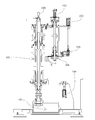
本発明の一実施形態に係る巻締め装置100は、図1に示すように、缶Cと蓋Fの巻締め工程を行うシーミングターレット101と、シーミングターレット101に蓋Fが載置された缶Cを供給する搬入コンベア102と、蓋Fを供給する蓋供給装置105及び蓋搬送ターレット106からなる蓋供給ユニット104と、巻締め後の缶CMをシーミングターレット101から搬出するディスチャージターレット107と、缶CMをさらにディスチャージターレット107から外部に搬出する搬出コンベア108を備えている。
そして、シーミングターレット101に、蓋Fが載置された缶Cを搬入コンベア102により供給することによって、後述する缶載置ユニット110のプレート112の昇降を不要とした、チャックユニット120及びシーミングユニット130による巻締めが行われる。
シーミングターレット101、ディスチャージターレット107及び蓋搬送ターレット106には、それぞれ外周部に缶C、CM及び蓋Fを個別収容して搬送するポケットPが設けられており、搬入コンベア102には、缶Cと個別に係合して搬送するアタッチメント103が設けられている。
シーミングターレット101、ディスチャージターレット107及び蓋搬送ターレット106の回転速度、搬入コンベア102のアタッチメント103の移動速度、及び、各ポケットP、アタッチメント103の連動タイミングは、各ターレット、コンベア間で缶C、CM及び蓋Fが円滑に受け渡されるように調整可能に設計されている。
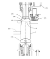
缶Cと蓋Fの巻締め工程を行うシーミングターレット101は、図3に示すように、各ポケットPにそれぞれ、缶Cを載置する缶載置ユニット110と、缶載置ユニット110に対向して設けられたチャックユニット120と、蓋Fを缶Cに巻締めるシーミングロール131を有するシーミングユニット130とを備えている。
シーミングターレット101は、シーミングターレットの駆動モータ151により回転駆動され、ポケット位置検出エンコーダ155によって、その回転位相からポケット位置を検出可能に構成されている。
また、搬入コンベア102の搬送経路には、搬入コンベア102のアタッチメント103の位置を検出する光電管、近接スィッチ、レーザー等から成るピッチセンサーSが設けられ、このピッチセンサーSの出力により、シーミングターレット101と蓋搬送ターレット106のポケットPに対するアタッチメント103の位置が制御される。
このように検出、制御することにより、調整作業をさらに容易に行うことが可能となるとともに、各ポケットPやアタッチメント103の位置の誤差や、稼働中の位置の変動にも自動的に検出して調整することが可能となり、巻締め精度を向上させ、巻締め処理の高速化を図ることが可能となる。蓋供給装置105、蓋搬送ターレット106、搬入コンベア102は、図2に示すように、それぞれ、蓋供給装置105の駆動モータ153、蓋搬送ターレット106の駆動モータ152、搬入コンベア102の駆動モータ154により駆動される。
それぞれのモータは、サーボモータが採用され、速度、タイミングを個別に調整可能に構成されるとともに、ポケット位置検出エンコーダ155の出力に応じてシーミングターレット101の速度、タイミングの変動にも追従可能に構成されている。
このように、蓋供給装置105、蓋搬送ターレット106、搬入コンベア102が、それぞれ独立して制御される駆動源で駆動されることにより、缶の寸法、重量、巻締寸法等に応じた動作タイミングを、運転を止めることなく個別に最適に調整でき、調整作業を短時間で容易に行うことができる。
また、駆動源がサーボモータであることにより、調整を電気的な制御指令で行うことができるとともに、フィードバック制御も可能となり、さらに調整作業を短時間で容易に行うことができる。
このように、蓋供給装置105、蓋搬送ターレット106、搬入コンベア102が、それぞれ独立して制御される駆動源で駆動されることにより、缶の寸法、重量、巻締寸法等に応じた動作タイミングを、運転を止めることなく個別に最適に調整でき、調整作業を短時間で容易に行うことができる。
また、駆動源がサーボモータであることにより、調整を電気的な制御指令で行うことができるとともに、フィードバック制御も可能となり、さらに調整作業を短時間で容易に行うことができる。
なお、ディスチャージターレット107、搬出コンベア108は巻締め後の缶CMのみの受渡しを行い、ある程度の速度、タイミングのずれは許容されるため、シーミングターレット101の駆動モータ151から機械的に伝動機構を介して駆動する等、適宜の駆動源を用いればよい。
また、精度、速度の面で、速度やタイミングを容易に調整ができるような設計であれば、蓋供給装置105、蓋搬送ターレット106、搬入コンベア102についても、シーミングターレット101の駆動モータ151から機械的に伝動機構を介して駆動する等、適宜の駆動源を用いればよい。
また、精度、速度の面で、速度やタイミングを容易に調整ができるような設計であれば、蓋供給装置105、蓋搬送ターレット106、搬入コンベア102についても、シーミングターレット101の駆動モータ151から機械的に伝動機構を介して駆動する等、適宜の駆動源を用いればよい。
缶載置ユニット110は、缶Cを載置するプレート112と、プレート112をスプリング、圧縮エア等の弾性的に上方に押圧する押圧機構111を有している。
また、缶載置ユニット110は、前記押圧機構111によるプレート112の上下動以外には上下動しないように構成されている。
また、缶載置ユニット110は、前記押圧機構111によるプレート112の上下動以外には上下動しないように構成されている。
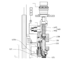
チャックユニット120は、図3に示すように、上下動カム123と上下動カムフォロア124からなるチャックユニット120の上下動機構122によって上下動する。
チャックユニット120の上下動カム123は固定的に設けられており、シーミングターレット101が回転することで、チャックユニット120の上下動カムフォロア124がカムプロフィールに倣って移動し、チャックユニット120のチャック121が位置に応じて上下動する。
また、チャックユニット120と、後述するチャック121の駆動モータ156にそれぞれ取り付けるギヤの幅(厚み)を適宜設定して、チャックユニット120の上下動における駆動モータ156によるチャック121の回転の制御が行われる。
なお、前記した回転の制御は、適宜手段を採用、或いは付加すれば良い。
チャックユニット120の上下動カム123は固定的に設けられており、シーミングターレット101が回転することで、チャックユニット120の上下動カムフォロア124がカムプロフィールに倣って移動し、チャックユニット120のチャック121が位置に応じて上下動する。
また、チャックユニット120と、後述するチャック121の駆動モータ156にそれぞれ取り付けるギヤの幅(厚み)を適宜設定して、チャックユニット120の上下動における駆動モータ156によるチャック121の回転の制御が行われる。
なお、前記した回転の制御は、適宜手段を採用、或いは付加すれば良い。
一方、シーミングユニット130は、同様に図3に示すように、上下動カム134と上下動カムフォロア135からなるシーミングユニット130の上下動機構133によってシーミングロール131が上下動する。
シーミングユニット130の上下動カム134は固定的に設けられており、シーミングターレット101が回転することで、シーミングユニット130の上下動カムフォロア135がカムプロフィールに倣って移動し、シーミングユニット130が位置に応じて上下動する。
また、シーミングユニット130は、ロール揺動軸132の上方にスプラインKを備え、ロール揺動軸132の伸縮と回転を可能とし、前記した上下動機構133によるシーミングロール131の上下動と、後述するロール揺動軸132の駆動モータ158によるシーミングロール131の巻締め動作、押し付けが行われる。
なお、シーミングロール131の上下動、巻締め動作、押し付けを可能とする手段は、ロール揺動軸132のスプラインK等には限定されず、適宜手段を採用、付加すれば良い。
このように、缶載置ユニット110が缶を載置するプレート112を弾性的に上方に押圧する押圧機構111を有し、チャックユニット120及びシーミングユニット130を、上下動可能とすることで、缶載置ユニット110のプレート112を自転した状態で昇降させる必要がないため、搬入コンベア102から缶載置ユニット110に缶が乗り移る際に缶Cが上下動することなく姿勢が安定し、ガイドやシーミングターレット101のポケットPによる凹み、その凹みに起因する巻締め時の座屈を防止することができ、巻締め精度の向上を図ることが可能となる。
また、缶載置ユニット110のプレート112とチャックユニット120のチャック121の自転の駆動源は、図3に示すように、それぞれ独立して制御されるサーボモータで構成された缶載置ユニット110の駆動モータ157、チャック121の駆動モータ156を駆動源として駆動される。
このような駆動により、プレート112及びチャック121の回転の開始や加速のタイミングをそれぞれ独立して制御でき、操作盤等により運転を止めることなく個別に最適に調整できるため、調整作業を短時間で容易に行うことが可能となるとともに、運転中の変動にも対処することが可能となる。
また、プレート112及びチャック121の回転の開始や加速のタイミングを制御して、缶に載置された蓋に、自転するチャック121を嵌合させる際に、プレート112及びチャック121の自転を停止、低速状態に制御し、回転中心のずれを低減してガイド部材等との接触による缶の凹み、傷付き等を防止し、また、チャック121による蓋のセンターリング性能を向上させることができる。
一方、シーミングユニット130のロール揺動軸132の駆動源は、独立して制御されるサーボモータで構成されたロール揺動軸132の駆動モータ158を駆動源とすることで、シーミングロール131の巻締め動作のタイミングや押し付け量を独立して制御でき、操作盤等により運転を止めることなく個別に最適に調整できるため、調整作業を短時間で容易に行うことが可能となるとともに、運転中の変動にも対処することが可能となる。
なお、前述したように、プレート112とチャック121の自転、ロール揺動軸132の駆動源をサーボモータとすることにより、調整を電気的な制御指令で行うことができるとともに、フィードバック制御も可能となり、さらに調整作業を短時間で容易に行うことが可能となる。
チャックユニット120は、図4に示すように、蓋Fを押さえるチャック121を有しており、チャック121が下降してチャック外周部126が、シーミングターレット101に供給される缶Cに載置された蓋Fに嵌合することで、蓋Fのセンターリングを行ない、缶載置ユニット110のプレート112の昇降を不要とした、チャックユニット120及びシーミングユニット130による巻締めが行われる。
このように、チャック121が缶Cに載置された蓋Fのセンターリングを行うとともに蓋Fを押さえることにより、蓋Fの位置補正が容易となり、偏荷重が加わることなく缶の座屈が防止されるとともに、缶の薄肉化を図ることが可能となる。
このように、チャック121が缶Cに載置された蓋Fのセンターリングを行うとともに蓋Fを押さえることにより、蓋Fの位置補正が容易となり、偏荷重が加わることなく缶の座屈が防止されるとともに、缶の薄肉化を図ることが可能となる。
一方、図5に示すチャック121他の形態は、チャック121に負圧吸入孔125を形成し、チャック121で蓋Fを吸着してセンターリングを行う。
図6に示すように、通常、搬入コンベア102、蓋搬送ターレット106の速度、タイミングは、缶Cと蓋Fの中心が合流点Gで一致するように、シーミングターレット101の速度、タイミングに合わせて調整されている。
本形態では、蓋Fをチャック121に負圧吸引する位置Gbが、通常の合流点Gよりもシーミングターレット101の上流側となるよう、蓋搬送ターレット106が配置されている。そして、上流側の蓋Fをチャック121に負圧吸引する位置Gbにおいて、蓋Fを駆動モータ(サーボモータ)156により回転が制御されたチャック121に負圧吸引して、蓋のセンターリングが行われる。
蓋Fをチャック121に吸着後、下降させて蓋Fを缶Cに載置することにより、缶載置ユニット110のプレート112の昇降を不要とした、チャックユニット120及びシーミングユニット130による巻締めが行われる。
このように、チャック121で蓋Fを負圧吸引してセンターリングを行うことで、チャック外周部126を蓋Fに嵌合させ、予めチャック121と蓋Fを吸着させて嵌合力を増加させることにより、スリップによる巻締め不良が防止される。このため、缶Cに付与する軸荷重の低減が可能となり、缶Cの座屈が防止されるとともに薄肉化を図ることが可能となる。
また、缶Cに蓋Fを載置する際に、チャック121による吸着によって、蓋Fが確実にセンターリングされているため、偏荷重による座屈が防止される。
以上のように構成された巻締め装置100の動作について説明する。
蓋Fを巻締め前の缶Cは、搬入コンベア102の各アタッチメント103に係合して搬送され、シーミングターレット101に向かう。
一方、蓋Fは、蓋供給装置105から1枚ずつ切り出されて蓋搬送ターレット106の各ポケットPに受け渡され、蓋搬送ターレット106の回転により、缶Cの上方に向かう(図1参照)。
搬入コンベア102、蓋搬送ターレット106の速度、タイミングは、缶Cと蓋Fの中心が搬入コンベア102上の所定の位置で一致するように、シーミングターレット101の速度、タイミングに合わせて調整されており、所定の位置で蓋Fが缶Cに向かって落下し、搬入コンベア102上の缶Cに蓋Fが載置される。
蓋Fを巻締め前の缶Cは、搬入コンベア102の各アタッチメント103に係合して搬送され、シーミングターレット101に向かう。
一方、蓋Fは、蓋供給装置105から1枚ずつ切り出されて蓋搬送ターレット106の各ポケットPに受け渡され、蓋搬送ターレット106の回転により、缶Cの上方に向かう(図1参照)。
搬入コンベア102、蓋搬送ターレット106の速度、タイミングは、缶Cと蓋Fの中心が搬入コンベア102上の所定の位置で一致するように、シーミングターレット101の速度、タイミングに合わせて調整されており、所定の位置で蓋Fが缶Cに向かって落下し、搬入コンベア102上の缶Cに蓋Fが載置される。
その後、蓋Fが載置された缶Cは、搬入コンベア102からシーミングターレット101に受け渡され、缶載置ユニット110の駆動モータ(サーボモータ)157によって、回転が制御された缶載置ユニット110のプレート112上に載置される。
次いで、駆動モータ(サーボモータ)156によって、回転が制御されたチャックユニット120を、上下動機構122によって下降させ、チャックユニット120のチャック121を蓋Fに嵌合する。
蓋Fが嵌合した缶Cは、缶載置ユニット110の押圧機構111の押圧力に抗して、巻締めに必要な一定の軸荷重で、プレート112とチャック121に挟持されるとともに、チャック121による蓋Fのセンターリングが行われ、同時に嵌合している缶Cもセンターリングが行われる。
なお、前述したように、チャック121による蓋Fのセンターリング、缶Cへの蓋Fの載置は、チャック121に吸着手段の負圧吸入孔125を形成し、蓋Fを吸着してセンターリングを行い、吸着後、チャック121を下降させて缶Cへの蓋Fの載置を行っても良い。
そして、シーミングターレット101がさらに回転し、挟持された蓋Fと缶Cが図1に示す巻締め区間Eに達する前に、巻締めに必要な回転数まで加速される。
一方、シーミングユニット130を上下動機構133によって下降させて、シーミングロール131を蓋Fが嵌合した缶Cの巻締め部位に位置させ、巻締め区間Eを通過中に、シーミングユニット130のロール揺動軸132を駆動モータ(サーボモータ)158によって作動させ、シーミングロール131を側方から押し付けて巻締めが行われる。
図では、シーミングロール131が1つしか記載していないが、実際はロール揺動軸132に1次巻締め用、2次巻締め用の2つのシーミングロール131が備えられており、巻締め区間Eを通過中に順次押し付けて巻締めが完了する。
図では、シーミングロール131が1つしか記載していないが、実際はロール揺動軸132に1次巻締め用、2次巻締め用の2つのシーミングロール131が備えられており、巻締め区間Eを通過中に順次押し付けて巻締めが完了する。
巻締めが完了した缶CMは、シーミングターレット101からディスチャージターレット107に受け渡され、さらに、ディスチャージターレット107から搬出コンベア108に受け渡されて、検査、梱包等の次工程に搬出される。
図7は、本発明の巻締め装置におけるチャックユニット及びシーミングユニットの他の形態を示し、チャックユニット120bとシーミングユニット130bが、ハウジング136で一体に構成され、上下動カム144及び上下動カムフォロア145からなるチャックユニット120bとシーミングユニット130bの上下動機構143で、チャック121とシーミングロール131を一体として上下動するように構成したものである。
このような構成とすることにより、チャックユニット120bとシーミングユニット130bの上下位置関係の精度を向上することができるとともに、熱変形等によるチャックユニット120bとシーミングユニット130bの上下位置ずれを防止して巻締め精度を向上し、処理の高速化を図ることができる。
このような構成とすることにより、チャックユニット120bとシーミングユニット130bの上下位置関係の精度を向上することができるとともに、熱変形等によるチャックユニット120bとシーミングユニット130bの上下位置ずれを防止して巻締め精度を向上し、処理の高速化を図ることができる。
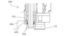
図8、図9は、本発明の巻締め装置におけるチャックユニットのさらに他の形態を示し、図に示すように、チャックユニット120cの最下端のオイルシール129cの上部にチャック121cの回転に伴って回転する羽根ポンプ127cを設け、羽根ポンプ127cの回転によって潤滑油を排出チューブ128cから排出するものである。
このことで、オイルシール129c上に貯留する潤滑油を最小限とし、チャック121cの回転によるオイルシール129cからの潤滑油の漏れ、汚損を防止することができる。
このことで、オイルシール129c上に貯留する潤滑油を最小限とし、チャック121cの回転によるオイルシール129cからの潤滑油の漏れ、汚損を防止することができる。
また、図10は、本発明の巻締め装置における缶載置ユニット110の押圧機構111の他の形態を示し、図に示すように、圧縮エア等の圧力流体によりプレート112を弾性的に上方に押圧する機構を用いてもよい。
この押圧機構111bは、シリンダ空間113の上方にプレート112を固定したピストン114が挿入されて構成されており、圧縮エア等の圧力流体がシリンダ空間113内に供給されることで、プレート112を弾性的に上方に押圧する。
押圧機構111bを用いれば、全てのポケットPで一定の押付力が得られるとともに、プレート112の押圧下降量にかかわらず、一定の押付力が得られるため、調整が極めて容易であり、運転中に変動することも防止できる。
また、この押圧機構111bを用いた場合には、巻締め中に缶Cの高さが微小に減少する際に、前述したチャックユニット120の上下動カム123、シーミングユニット130の上下動カム134のカムプロフィールと、実際の缶高減少量の誤差を押圧機構111bで吸収しても軸荷重が変動せず、巻締め精度を向上させ、処理の高速化を図ることが可能となる。
図11は、さらに他の形態の押圧機構を有する缶載置ユニット110cを示し、押圧機構111cは、図に示すように、ダイヤフラム118cによって、プレート112c昇降させるピストン114cをシリンダ空間113cに対して気密に保つように構成されている。
このことで、ピストン114cの昇降の際のシール抵抗がなく、円滑にプレート112cを昇降させることができる。
このことで、ピストン114cの昇降の際のシール抵抗がなく、円滑にプレート112cを昇降させることができる。
Claims (12)
- 缶を載置する缶載置ユニットと、前記缶載置ユニットに対向して設けられたチャックユニットと、蓋を缶に巻締めるシーミングユニットを備えた巻締め装置であって、
前記缶載置ユニットが、缶を載置するプレートを弾性的に上方に押圧する押圧機構を有し、
前記チャックユニット及びシーミングユニットが、上下動可能に構成されていることを特徴とする巻締め装置。 - 前記チャックユニットとシーミングユニットが、単一のカム機構で上下動するように一体に形成されていることを特徴とする請求項1に記載の巻締め装置。
- 前記缶載置ユニットのプレート及びチャックユニットのチャックの自転、前記シーミングユニットのシーミングロールの巻締め動作を、それぞれ独立して制御される駆動源で行うことを特徴とする請求項1又は2に記載の巻締め装置。
- 前記巻締め装置が、シーミングターレットに缶を供給する搬入コンベアと、蓋を供給する蓋供給装置及び蓋搬送ターレットからなる蓋供給ユニットを備え、前記搬入コンベア、蓋供給装置及び蓋搬送ターレットが、それぞれ独立して制御される駆動源を有することを特徴とする請求項1乃至3のいずれかに記載の巻締め装置。
- 前記駆動源が、サーボモータであることを特徴とする請求項3又は4に記載の巻締め装置。
- 前記シーミングターレットに、蓋が載置された缶を搬入コンベアにより供給する請求項4に記載の巻締め装置。
- 前記チャックユニットは、前記チャックのみが蓋と当接し、
前記チャックを下降させて蓋のセンターリングを行うとともに蓋を押さえることを特徴とする請求項1に記載の巻締め装置。 - 前記チャックが蓋吸着手段を有し、前記蓋吸着手段により蓋のセンターリングを行い、吸着後、前記チャックを下降させて蓋を缶に載置することを特徴とする請求項1乃至5のいずれかに記載の巻締め装置。
- 前記シーミングターレットが、ポケットの位置を検出する検出手段を有し、
前記搬入コンベアの搬送経路には、前記搬入コンベアのアタッチメントを検出するピッチセンサーを有し、
前記検出手段の出力により、前記搬入コンベアの速度を制御するとともに、
前記ピッチセンサーの出力により、前記シーミングターレットと前記蓋搬送ターレットのポケットに対する前記アタッチメントの位置を制御することを特徴とする請求項4乃至8のいずれかに記載の巻締め装置。 - 前記チャックユニットが、潤滑油を強制排出する回転羽根ポンプ機構を有することを特徴とする請求項1乃至9のいずれかに記載の巻締め装置。
- 前記押圧機構が、流体圧で作動するように構成されていることを特徴とする請求項1乃至10のいずれかに記載の巻締め装置。
- 前記押圧機構が、流体圧流体圧をシールするダイヤフラムを有することを特徴とする請求項11に記載の巻締め装置。
Priority Applications (3)
| Application Number | Priority Date | Filing Date | Title |
|---|---|---|---|
| CN201680032737.9A CN107635689A (zh) | 2015-06-12 | 2016-06-01 | 卷封装置 |
| EP16807356.7A EP3308872A4 (en) | 2015-06-12 | 2016-06-01 | CRIMPING DEVICE |
| US15/811,934 US20180065168A1 (en) | 2015-06-12 | 2017-11-14 | Seaming device |
Applications Claiming Priority (6)
| Application Number | Priority Date | Filing Date | Title |
|---|---|---|---|
| JP2015119614 | 2015-06-12 | ||
| JP2015-119614 | 2015-06-12 | ||
| JP2015137411 | 2015-07-09 | ||
| JP2015-137411 | 2015-07-09 | ||
| JP2016-008012 | 2016-01-19 | ||
| JP2016008012A JP6877875B2 (ja) | 2015-06-12 | 2016-01-19 | 巻締め装置 |
Related Child Applications (1)
| Application Number | Title | Priority Date | Filing Date |
|---|---|---|---|
| US15/811,934 Continuation US20180065168A1 (en) | 2015-06-12 | 2017-11-14 | Seaming device |
Publications (1)
| Publication Number | Publication Date |
|---|---|
| WO2016199649A1 true WO2016199649A1 (ja) | 2016-12-15 |
Family
ID=57503906
Family Applications (1)
| Application Number | Title | Priority Date | Filing Date |
|---|---|---|---|
| PCT/JP2016/066272 WO2016199649A1 (ja) | 2015-06-12 | 2016-06-01 | 巻締め装置 |
Country Status (1)
| Country | Link |
|---|---|
| WO (1) | WO2016199649A1 (ja) |
Cited By (3)
| Publication number | Priority date | Publication date | Assignee | Title |
|---|---|---|---|---|
| CN106744574A (zh) * | 2016-12-20 | 2017-05-31 | 舟山市普陀博达机械制造有限公司 | 一种多功能机的传动装置 |
| WO2021181764A1 (ja) * | 2020-03-13 | 2021-09-16 | 東洋製罐グループエンジニアリング株式会社 | 巻締め装置 |
| JP7458213B2 (ja) | 2020-03-13 | 2024-03-29 | 東洋製罐グループエンジニアリング株式会社 | 巻締め装置 |
Citations (7)
| Publication number | Priority date | Publication date | Assignee | Title |
|---|---|---|---|---|
| JPS62187530A (ja) * | 1986-02-12 | 1987-08-15 | Toyo Seikan Kaisha Ltd | 巻締装置における缶センタ−リング方法及びその方法に使用する缶蓋 |
| JPS62244537A (ja) * | 1986-04-17 | 1987-10-24 | Toyo Seikan Kaisha Ltd | 罐巻締方法及びその装置 |
| JPS635833A (ja) * | 1986-06-27 | 1988-01-11 | Toyo Seikan Kaisha Ltd | 巻締機のリフタ−装置 |
| JPH10508255A (ja) * | 1994-11-03 | 1998-08-18 | カーノードメタルボックス ピーエルシー | シーミング装置 |
| JP2001259766A (ja) * | 2000-03-23 | 2001-09-25 | Mitsuba Denyosha:Kk | 缶体の製造装置 |
| JP2007014982A (ja) * | 2005-07-07 | 2007-01-25 | Niizato Kiko Kk | Ncサーボシーマー |
| JP2009220178A (ja) * | 2008-02-19 | 2009-10-01 | Universal Seikan Kk | 缶の巻締め装置および缶の製造方法 |
-
2016
- 2016-06-01 WO PCT/JP2016/066272 patent/WO2016199649A1/ja active Application Filing
Patent Citations (7)
| Publication number | Priority date | Publication date | Assignee | Title |
|---|---|---|---|---|
| JPS62187530A (ja) * | 1986-02-12 | 1987-08-15 | Toyo Seikan Kaisha Ltd | 巻締装置における缶センタ−リング方法及びその方法に使用する缶蓋 |
| JPS62244537A (ja) * | 1986-04-17 | 1987-10-24 | Toyo Seikan Kaisha Ltd | 罐巻締方法及びその装置 |
| JPS635833A (ja) * | 1986-06-27 | 1988-01-11 | Toyo Seikan Kaisha Ltd | 巻締機のリフタ−装置 |
| JPH10508255A (ja) * | 1994-11-03 | 1998-08-18 | カーノードメタルボックス ピーエルシー | シーミング装置 |
| JP2001259766A (ja) * | 2000-03-23 | 2001-09-25 | Mitsuba Denyosha:Kk | 缶体の製造装置 |
| JP2007014982A (ja) * | 2005-07-07 | 2007-01-25 | Niizato Kiko Kk | Ncサーボシーマー |
| JP2009220178A (ja) * | 2008-02-19 | 2009-10-01 | Universal Seikan Kk | 缶の巻締め装置および缶の製造方法 |
Non-Patent Citations (1)
| Title |
|---|
| See also references of EP3308872A4 * |
Cited By (3)
| Publication number | Priority date | Publication date | Assignee | Title |
|---|---|---|---|---|
| CN106744574A (zh) * | 2016-12-20 | 2017-05-31 | 舟山市普陀博达机械制造有限公司 | 一种多功能机的传动装置 |
| WO2021181764A1 (ja) * | 2020-03-13 | 2021-09-16 | 東洋製罐グループエンジニアリング株式会社 | 巻締め装置 |
| JP7458213B2 (ja) | 2020-03-13 | 2024-03-29 | 東洋製罐グループエンジニアリング株式会社 | 巻締め装置 |
Similar Documents
| Publication | Publication Date | Title |
|---|---|---|
| JP6877875B2 (ja) | 巻締め装置 | |
| EP3117920B1 (en) | A sheet material feeding apparatus | |
| US10479619B2 (en) | Separator suction device with rotary actuator | |
| WO2016199649A1 (ja) | 巻締め装置 | |
| JP5794660B2 (ja) | 堆積体から印刷物を分離するための方法および装置 | |
| JPH10163677A (ja) | 回路部品装着システム | |
| JP2009298417A (ja) | 袋詰包装における袋口シール装置及び方法 | |
| JP6679968B2 (ja) | 巻締め装置 | |
| JP6671185B2 (ja) | 巻締め装置 | |
| KR100588551B1 (ko) | 프레스 라인의 소재 이송장치 | |
| JP6877874B2 (ja) | 巻締め装置 | |
| JPH10159930A (ja) | 回路部品搬送装置 | |
| WO2016199648A1 (ja) | 巻締め装置 | |
| JP6671186B2 (ja) | 巻締め装置 | |
| JP3745849B2 (ja) | 回路部品搬送装置 | |
| JP4162741B2 (ja) | 回路部品装着システム | |
| US20230068764A1 (en) | Seaming device for sealing a container | |
| JPH04189793A (ja) | サーボ式キャッパ | |
| KR102496156B1 (ko) | 간격 조절이 용이한 어태치먼트 벨트 | |
| US7399152B2 (en) | Apparatus for double seaming containers | |
| CN109139720B (en) | Cage ball adding device applied to hub bearing | |
| US20240091898A1 (en) | Work polishing apparatus and work polishing method | |
| CN212860849U (zh) | 自动喷码装置 | |
| JP3594749B2 (ja) | 歯車位置決め供給装置 | |
| WO2018025688A1 (ja) | 巻締め装置 |
Legal Events
| Date | Code | Title | Description |
|---|---|---|---|
| 121 | Ep: the epo has been informed by wipo that ep was designated in this application |
Ref document number: 16807356 Country of ref document: EP Kind code of ref document: A1 |
|
| NENP | Non-entry into the national phase |
Ref country code: DE |
|
| WWE | Wipo information: entry into national phase |
Ref document number: 2016807356 Country of ref document: EP |