WO2016199643A1 - 水素充填用ホース - Google Patents
水素充填用ホース Download PDFInfo
- Publication number
- WO2016199643A1 WO2016199643A1 PCT/JP2016/066230 JP2016066230W WO2016199643A1 WO 2016199643 A1 WO2016199643 A1 WO 2016199643A1 JP 2016066230 W JP2016066230 W JP 2016066230W WO 2016199643 A1 WO2016199643 A1 WO 2016199643A1
- Authority
- WO
- WIPO (PCT)
- Prior art keywords
- layer
- hose
- fiber
- less
- wire
- Prior art date
Links
- 239000010410 layer Substances 0.000 claims abstract description 196
- 239000000835 fiber Substances 0.000 claims abstract description 112
- 230000003014 reinforcing effect Effects 0.000 claims abstract description 52
- 239000002344 surface layer Substances 0.000 claims abstract description 49
- UFHFLCQGNIYNRP-UHFFFAOYSA-N Hydrogen Chemical compound [H][H] UFHFLCQGNIYNRP-UHFFFAOYSA-N 0.000 claims abstract description 46
- 239000002184 metal Substances 0.000 claims abstract description 24
- 238000009954 braiding Methods 0.000 claims abstract description 20
- 229920005992 thermoplastic resin Polymers 0.000 claims abstract description 13
- 239000007789 gas Substances 0.000 claims abstract description 7
- 229910052739 hydrogen Inorganic materials 0.000 claims description 49
- 239000001257 hydrogen Substances 0.000 claims description 49
- 230000002093 peripheral effect Effects 0.000 claims description 17
- 230000035699 permeability Effects 0.000 claims description 11
- -1 polyparaphenylene benzbisoxazole Polymers 0.000 claims description 4
- 230000005540 biological transmission Effects 0.000 abstract 1
- 230000008859 change Effects 0.000 description 38
- 150000002431 hydrogen Chemical class 0.000 description 15
- 238000012360 testing method Methods 0.000 description 6
- 238000011156 evaluation Methods 0.000 description 5
- 230000004888 barrier function Effects 0.000 description 4
- 230000000052 comparative effect Effects 0.000 description 4
- 230000006378 damage Effects 0.000 description 4
- 238000002788 crimping Methods 0.000 description 3
- 239000000446 fuel Substances 0.000 description 3
- 238000000034 method Methods 0.000 description 3
- 230000002787 reinforcement Effects 0.000 description 3
- 230000003068 static effect Effects 0.000 description 3
- 238000013459 approach Methods 0.000 description 2
- 230000008602 contraction Effects 0.000 description 2
- 238000011161 development Methods 0.000 description 2
- 230000008014 freezing Effects 0.000 description 2
- 238000007710 freezing Methods 0.000 description 2
- 238000010030 laminating Methods 0.000 description 2
- 210000002445 nipple Anatomy 0.000 description 2
- 239000012779 reinforcing material Substances 0.000 description 2
- 229920000049 Carbon (fiber) Polymers 0.000 description 1
- 229920000219 Ethylene vinyl alcohol Polymers 0.000 description 1
- 239000004677 Nylon Substances 0.000 description 1
- 229920000571 Nylon 11 Polymers 0.000 description 1
- 229920002292 Nylon 6 Polymers 0.000 description 1
- 229920002302 Nylon 6,6 Polymers 0.000 description 1
- 229930182556 Polyacetal Natural products 0.000 description 1
- YZCKVEUIGOORGS-IGMARMGPSA-N Protium Chemical compound [1H] YZCKVEUIGOORGS-IGMARMGPSA-N 0.000 description 1
- 229910000831 Steel Inorganic materials 0.000 description 1
- 230000009471 action Effects 0.000 description 1
- 239000004760 aramid Substances 0.000 description 1
- 229920006231 aramid fiber Polymers 0.000 description 1
- 239000004917 carbon fiber Substances 0.000 description 1
- 230000015556 catabolic process Effects 0.000 description 1
- 239000000470 constituent Substances 0.000 description 1
- 238000005520 cutting process Methods 0.000 description 1
- 230000007423 decrease Effects 0.000 description 1
- 239000002828 fuel tank Substances 0.000 description 1
- 125000004435 hydrogen atom Chemical group [H]* 0.000 description 1
- 230000006872 improvement Effects 0.000 description 1
- 230000007257 malfunction Effects 0.000 description 1
- 238000004519 manufacturing process Methods 0.000 description 1
- 229920001778 nylon Polymers 0.000 description 1
- 239000012466 permeate Substances 0.000 description 1
- 229920000728 polyester Polymers 0.000 description 1
- 229920006324 polyoxymethylene Polymers 0.000 description 1
- 229920002635 polyurethane Polymers 0.000 description 1
- 239000004814 polyurethane Substances 0.000 description 1
- 229920005989 resin Polymers 0.000 description 1
- 239000011347 resin Substances 0.000 description 1
- 238000007789 sealing Methods 0.000 description 1
- 229910001220 stainless steel Inorganic materials 0.000 description 1
- 239000010959 steel Substances 0.000 description 1
- 230000002195 synergetic effect Effects 0.000 description 1
Images


Classifications
-
- F—MECHANICAL ENGINEERING; LIGHTING; HEATING; WEAPONS; BLASTING
- F16—ENGINEERING ELEMENTS AND UNITS; GENERAL MEASURES FOR PRODUCING AND MAINTAINING EFFECTIVE FUNCTIONING OF MACHINES OR INSTALLATIONS; THERMAL INSULATION IN GENERAL
- F16L—PIPES; JOINTS OR FITTINGS FOR PIPES; SUPPORTS FOR PIPES, CABLES OR PROTECTIVE TUBING; MEANS FOR THERMAL INSULATION IN GENERAL
- F16L11/00—Hoses, i.e. flexible pipes
- F16L11/04—Hoses, i.e. flexible pipes made of rubber or flexible plastics
- F16L11/08—Hoses, i.e. flexible pipes made of rubber or flexible plastics with reinforcements embedded in the wall
- F16L11/085—Hoses, i.e. flexible pipes made of rubber or flexible plastics with reinforcements embedded in the wall comprising one or more braided layers
- F16L11/086—Hoses, i.e. flexible pipes made of rubber or flexible plastics with reinforcements embedded in the wall comprising one or more braided layers two layers
-
- B—PERFORMING OPERATIONS; TRANSPORTING
- B32—LAYERED PRODUCTS
- B32B—LAYERED PRODUCTS, i.e. PRODUCTS BUILT-UP OF STRATA OF FLAT OR NON-FLAT, e.g. CELLULAR OR HONEYCOMB, FORM
- B32B15/00—Layered products comprising a layer of metal
- B32B15/04—Layered products comprising a layer of metal comprising metal as the main or only constituent of a layer, which is next to another layer of the same or of a different material
- B32B15/08—Layered products comprising a layer of metal comprising metal as the main or only constituent of a layer, which is next to another layer of the same or of a different material of synthetic resin
- B32B15/09—Layered products comprising a layer of metal comprising metal as the main or only constituent of a layer, which is next to another layer of the same or of a different material of synthetic resin comprising polyesters
-
- B—PERFORMING OPERATIONS; TRANSPORTING
- B32—LAYERED PRODUCTS
- B32B—LAYERED PRODUCTS, i.e. PRODUCTS BUILT-UP OF STRATA OF FLAT OR NON-FLAT, e.g. CELLULAR OR HONEYCOMB, FORM
- B32B1/00—Layered products having a non-planar shape
- B32B1/08—Tubular products
-
- B—PERFORMING OPERATIONS; TRANSPORTING
- B32—LAYERED PRODUCTS
- B32B—LAYERED PRODUCTS, i.e. PRODUCTS BUILT-UP OF STRATA OF FLAT OR NON-FLAT, e.g. CELLULAR OR HONEYCOMB, FORM
- B32B15/00—Layered products comprising a layer of metal
- B32B15/02—Layer formed of wires, e.g. mesh
-
- B—PERFORMING OPERATIONS; TRANSPORTING
- B32—LAYERED PRODUCTS
- B32B—LAYERED PRODUCTS, i.e. PRODUCTS BUILT-UP OF STRATA OF FLAT OR NON-FLAT, e.g. CELLULAR OR HONEYCOMB, FORM
- B32B15/00—Layered products comprising a layer of metal
- B32B15/04—Layered products comprising a layer of metal comprising metal as the main or only constituent of a layer, which is next to another layer of the same or of a different material
- B32B15/08—Layered products comprising a layer of metal comprising metal as the main or only constituent of a layer, which is next to another layer of the same or of a different material of synthetic resin
- B32B15/095—Layered products comprising a layer of metal comprising metal as the main or only constituent of a layer, which is next to another layer of the same or of a different material of synthetic resin comprising polyurethanes
-
- B—PERFORMING OPERATIONS; TRANSPORTING
- B32—LAYERED PRODUCTS
- B32B—LAYERED PRODUCTS, i.e. PRODUCTS BUILT-UP OF STRATA OF FLAT OR NON-FLAT, e.g. CELLULAR OR HONEYCOMB, FORM
- B32B15/00—Layered products comprising a layer of metal
- B32B15/14—Layered products comprising a layer of metal next to a fibrous or filamentary layer
-
- B—PERFORMING OPERATIONS; TRANSPORTING
- B32—LAYERED PRODUCTS
- B32B—LAYERED PRODUCTS, i.e. PRODUCTS BUILT-UP OF STRATA OF FLAT OR NON-FLAT, e.g. CELLULAR OR HONEYCOMB, FORM
- B32B15/00—Layered products comprising a layer of metal
- B32B15/18—Layered products comprising a layer of metal comprising iron or steel
-
- B—PERFORMING OPERATIONS; TRANSPORTING
- B32—LAYERED PRODUCTS
- B32B—LAYERED PRODUCTS, i.e. PRODUCTS BUILT-UP OF STRATA OF FLAT OR NON-FLAT, e.g. CELLULAR OR HONEYCOMB, FORM
- B32B27/00—Layered products comprising a layer of synthetic resin
- B32B27/06—Layered products comprising a layer of synthetic resin as the main or only constituent of a layer, which is next to another layer of the same or of a different material
-
- B—PERFORMING OPERATIONS; TRANSPORTING
- B32—LAYERED PRODUCTS
- B32B—LAYERED PRODUCTS, i.e. PRODUCTS BUILT-UP OF STRATA OF FLAT OR NON-FLAT, e.g. CELLULAR OR HONEYCOMB, FORM
- B32B27/00—Layered products comprising a layer of synthetic resin
- B32B27/12—Layered products comprising a layer of synthetic resin next to a fibrous or filamentary layer
-
- B—PERFORMING OPERATIONS; TRANSPORTING
- B32—LAYERED PRODUCTS
- B32B—LAYERED PRODUCTS, i.e. PRODUCTS BUILT-UP OF STRATA OF FLAT OR NON-FLAT, e.g. CELLULAR OR HONEYCOMB, FORM
- B32B27/00—Layered products comprising a layer of synthetic resin
- B32B27/30—Layered products comprising a layer of synthetic resin comprising vinyl (co)polymers; comprising acrylic (co)polymers
- B32B27/306—Layered products comprising a layer of synthetic resin comprising vinyl (co)polymers; comprising acrylic (co)polymers comprising vinyl acetate or vinyl alcohol (co)polymers
-
- B—PERFORMING OPERATIONS; TRANSPORTING
- B32—LAYERED PRODUCTS
- B32B—LAYERED PRODUCTS, i.e. PRODUCTS BUILT-UP OF STRATA OF FLAT OR NON-FLAT, e.g. CELLULAR OR HONEYCOMB, FORM
- B32B27/00—Layered products comprising a layer of synthetic resin
- B32B27/34—Layered products comprising a layer of synthetic resin comprising polyamides
-
- B—PERFORMING OPERATIONS; TRANSPORTING
- B32—LAYERED PRODUCTS
- B32B—LAYERED PRODUCTS, i.e. PRODUCTS BUILT-UP OF STRATA OF FLAT OR NON-FLAT, e.g. CELLULAR OR HONEYCOMB, FORM
- B32B27/00—Layered products comprising a layer of synthetic resin
- B32B27/36—Layered products comprising a layer of synthetic resin comprising polyesters
-
- B—PERFORMING OPERATIONS; TRANSPORTING
- B32—LAYERED PRODUCTS
- B32B—LAYERED PRODUCTS, i.e. PRODUCTS BUILT-UP OF STRATA OF FLAT OR NON-FLAT, e.g. CELLULAR OR HONEYCOMB, FORM
- B32B27/00—Layered products comprising a layer of synthetic resin
- B32B27/40—Layered products comprising a layer of synthetic resin comprising polyurethanes
-
- B—PERFORMING OPERATIONS; TRANSPORTING
- B32—LAYERED PRODUCTS
- B32B—LAYERED PRODUCTS, i.e. PRODUCTS BUILT-UP OF STRATA OF FLAT OR NON-FLAT, e.g. CELLULAR OR HONEYCOMB, FORM
- B32B5/00—Layered products characterised by the non- homogeneity or physical structure, i.e. comprising a fibrous, filamentary, particulate or foam layer; Layered products characterised by having a layer differing constitutionally or physically in different parts
- B32B5/02—Layered products characterised by the non- homogeneity or physical structure, i.e. comprising a fibrous, filamentary, particulate or foam layer; Layered products characterised by having a layer differing constitutionally or physically in different parts characterised by structural features of a fibrous or filamentary layer
- B32B5/12—Layered products characterised by the non- homogeneity or physical structure, i.e. comprising a fibrous, filamentary, particulate or foam layer; Layered products characterised by having a layer differing constitutionally or physically in different parts characterised by structural features of a fibrous or filamentary layer characterised by the relative arrangement of fibres or filaments of different layers, e.g. the fibres or filaments being parallel or perpendicular to each other
-
- B—PERFORMING OPERATIONS; TRANSPORTING
- B32—LAYERED PRODUCTS
- B32B—LAYERED PRODUCTS, i.e. PRODUCTS BUILT-UP OF STRATA OF FLAT OR NON-FLAT, e.g. CELLULAR OR HONEYCOMB, FORM
- B32B5/00—Layered products characterised by the non- homogeneity or physical structure, i.e. comprising a fibrous, filamentary, particulate or foam layer; Layered products characterised by having a layer differing constitutionally or physically in different parts
- B32B5/22—Layered products characterised by the non- homogeneity or physical structure, i.e. comprising a fibrous, filamentary, particulate or foam layer; Layered products characterised by having a layer differing constitutionally or physically in different parts characterised by the presence of two or more layers which are next to each other and are fibrous, filamentary, formed of particles or foamed
- B32B5/24—Layered products characterised by the non- homogeneity or physical structure, i.e. comprising a fibrous, filamentary, particulate or foam layer; Layered products characterised by having a layer differing constitutionally or physically in different parts characterised by the presence of two or more layers which are next to each other and are fibrous, filamentary, formed of particles or foamed one layer being a fibrous or filamentary layer
- B32B5/26—Layered products characterised by the non- homogeneity or physical structure, i.e. comprising a fibrous, filamentary, particulate or foam layer; Layered products characterised by having a layer differing constitutionally or physically in different parts characterised by the presence of two or more layers which are next to each other and are fibrous, filamentary, formed of particles or foamed one layer being a fibrous or filamentary layer another layer next to it also being fibrous or filamentary
-
- D—TEXTILES; PAPER
- D04—BRAIDING; LACE-MAKING; KNITTING; TRIMMINGS; NON-WOVEN FABRICS
- D04C—BRAIDING OR MANUFACTURE OF LACE, INCLUDING BOBBIN-NET OR CARBONISED LACE; BRAIDING MACHINES; BRAID; LACE
- D04C1/00—Braid or lace, e.g. pillow-lace; Processes for the manufacture thereof
- D04C1/02—Braid or lace, e.g. pillow-lace; Processes for the manufacture thereof made from particular materials
-
- D—TEXTILES; PAPER
- D04—BRAIDING; LACE-MAKING; KNITTING; TRIMMINGS; NON-WOVEN FABRICS
- D04C—BRAIDING OR MANUFACTURE OF LACE, INCLUDING BOBBIN-NET OR CARBONISED LACE; BRAIDING MACHINES; BRAID; LACE
- D04C1/00—Braid or lace, e.g. pillow-lace; Processes for the manufacture thereof
- D04C1/06—Braid or lace serving particular purposes
-
- F—MECHANICAL ENGINEERING; LIGHTING; HEATING; WEAPONS; BLASTING
- F16—ENGINEERING ELEMENTS AND UNITS; GENERAL MEASURES FOR PRODUCING AND MAINTAINING EFFECTIVE FUNCTIONING OF MACHINES OR INSTALLATIONS; THERMAL INSULATION IN GENERAL
- F16L—PIPES; JOINTS OR FITTINGS FOR PIPES; SUPPORTS FOR PIPES, CABLES OR PROTECTIVE TUBING; MEANS FOR THERMAL INSULATION IN GENERAL
- F16L11/00—Hoses, i.e. flexible pipes
- F16L11/04—Hoses, i.e. flexible pipes made of rubber or flexible plastics
- F16L11/08—Hoses, i.e. flexible pipes made of rubber or flexible plastics with reinforcements embedded in the wall
- F16L11/085—Hoses, i.e. flexible pipes made of rubber or flexible plastics with reinforcements embedded in the wall comprising one or more braided layers
- F16L11/087—Hoses, i.e. flexible pipes made of rubber or flexible plastics with reinforcements embedded in the wall comprising one or more braided layers three or more layers
-
- B—PERFORMING OPERATIONS; TRANSPORTING
- B32—LAYERED PRODUCTS
- B32B—LAYERED PRODUCTS, i.e. PRODUCTS BUILT-UP OF STRATA OF FLAT OR NON-FLAT, e.g. CELLULAR OR HONEYCOMB, FORM
- B32B2250/00—Layers arrangement
- B32B2250/05—5 or more layers
-
- B—PERFORMING OPERATIONS; TRANSPORTING
- B32—LAYERED PRODUCTS
- B32B—LAYERED PRODUCTS, i.e. PRODUCTS BUILT-UP OF STRATA OF FLAT OR NON-FLAT, e.g. CELLULAR OR HONEYCOMB, FORM
- B32B2262/00—Composition or structural features of fibres which form a fibrous or filamentary layer or are present as additives
- B32B2262/02—Synthetic macromolecular fibres
- B32B2262/0261—Polyamide fibres
- B32B2262/0269—Aromatic polyamide fibres
-
- B—PERFORMING OPERATIONS; TRANSPORTING
- B32—LAYERED PRODUCTS
- B32B—LAYERED PRODUCTS, i.e. PRODUCTS BUILT-UP OF STRATA OF FLAT OR NON-FLAT, e.g. CELLULAR OR HONEYCOMB, FORM
- B32B2262/00—Composition or structural features of fibres which form a fibrous or filamentary layer or are present as additives
- B32B2262/10—Inorganic fibres
- B32B2262/103—Metal fibres
-
- B—PERFORMING OPERATIONS; TRANSPORTING
- B32—LAYERED PRODUCTS
- B32B—LAYERED PRODUCTS, i.e. PRODUCTS BUILT-UP OF STRATA OF FLAT OR NON-FLAT, e.g. CELLULAR OR HONEYCOMB, FORM
- B32B2262/00—Composition or structural features of fibres which form a fibrous or filamentary layer or are present as additives
- B32B2262/10—Inorganic fibres
- B32B2262/106—Carbon fibres, e.g. graphite fibres
-
- B—PERFORMING OPERATIONS; TRANSPORTING
- B32—LAYERED PRODUCTS
- B32B—LAYERED PRODUCTS, i.e. PRODUCTS BUILT-UP OF STRATA OF FLAT OR NON-FLAT, e.g. CELLULAR OR HONEYCOMB, FORM
- B32B2307/00—Properties of the layers or laminate
- B32B2307/50—Properties of the layers or laminate having particular mechanical properties
- B32B2307/54—Yield strength; Tensile strength
-
- B—PERFORMING OPERATIONS; TRANSPORTING
- B32—LAYERED PRODUCTS
- B32B—LAYERED PRODUCTS, i.e. PRODUCTS BUILT-UP OF STRATA OF FLAT OR NON-FLAT, e.g. CELLULAR OR HONEYCOMB, FORM
- B32B2307/00—Properties of the layers or laminate
- B32B2307/50—Properties of the layers or laminate having particular mechanical properties
- B32B2307/546—Flexural strength; Flexion stiffness
-
- B—PERFORMING OPERATIONS; TRANSPORTING
- B32—LAYERED PRODUCTS
- B32B—LAYERED PRODUCTS, i.e. PRODUCTS BUILT-UP OF STRATA OF FLAT OR NON-FLAT, e.g. CELLULAR OR HONEYCOMB, FORM
- B32B2307/00—Properties of the layers or laminate
- B32B2307/70—Other properties
- B32B2307/724—Permeability to gases, adsorption
- B32B2307/7242—Non-permeable
-
- B—PERFORMING OPERATIONS; TRANSPORTING
- B32—LAYERED PRODUCTS
- B32B—LAYERED PRODUCTS, i.e. PRODUCTS BUILT-UP OF STRATA OF FLAT OR NON-FLAT, e.g. CELLULAR OR HONEYCOMB, FORM
- B32B2307/00—Properties of the layers or laminate
- B32B2307/70—Other properties
- B32B2307/732—Dimensional properties
-
- B—PERFORMING OPERATIONS; TRANSPORTING
- B32—LAYERED PRODUCTS
- B32B—LAYERED PRODUCTS, i.e. PRODUCTS BUILT-UP OF STRATA OF FLAT OR NON-FLAT, e.g. CELLULAR OR HONEYCOMB, FORM
- B32B2307/00—Properties of the layers or laminate
- B32B2307/70—Other properties
- B32B2307/732—Dimensional properties
- B32B2307/734—Dimensional stability
-
- B—PERFORMING OPERATIONS; TRANSPORTING
- B32—LAYERED PRODUCTS
- B32B—LAYERED PRODUCTS, i.e. PRODUCTS BUILT-UP OF STRATA OF FLAT OR NON-FLAT, e.g. CELLULAR OR HONEYCOMB, FORM
- B32B2597/00—Tubular articles, e.g. hoses, pipes
-
- D—TEXTILES; PAPER
- D10—INDEXING SCHEME ASSOCIATED WITH SUBLASSES OF SECTION D, RELATING TO TEXTILES
- D10B—INDEXING SCHEME ASSOCIATED WITH SUBLASSES OF SECTION D, RELATING TO TEXTILES
- D10B2101/00—Inorganic fibres
- D10B2101/20—Metallic fibres
-
- D—TEXTILES; PAPER
- D10—INDEXING SCHEME ASSOCIATED WITH SUBLASSES OF SECTION D, RELATING TO TEXTILES
- D10B—INDEXING SCHEME ASSOCIATED WITH SUBLASSES OF SECTION D, RELATING TO TEXTILES
- D10B2331/00—Fibres made from polymers obtained otherwise than by reactions only involving carbon-to-carbon unsaturated bonds, e.g. polycondensation products
- D10B2331/14—Fibres made from polymers obtained otherwise than by reactions only involving carbon-to-carbon unsaturated bonds, e.g. polycondensation products polycondensates of cyclic compounds, e.g. polyimides, polybenzimidazoles
-
- D—TEXTILES; PAPER
- D10—INDEXING SCHEME ASSOCIATED WITH SUBLASSES OF SECTION D, RELATING TO TEXTILES
- D10B—INDEXING SCHEME ASSOCIATED WITH SUBLASSES OF SECTION D, RELATING TO TEXTILES
- D10B2403/00—Details of fabric structure established in the fabric forming process
- D10B2403/01—Surface features
- D10B2403/012—Alike front and back faces
- D10B2403/0122—Smooth surfaces, e.g. laminated or coated
-
- D—TEXTILES; PAPER
- D10—INDEXING SCHEME ASSOCIATED WITH SUBLASSES OF SECTION D, RELATING TO TEXTILES
- D10B—INDEXING SCHEME ASSOCIATED WITH SUBLASSES OF SECTION D, RELATING TO TEXTILES
- D10B2505/00—Industrial
- D10B2505/12—Vehicles
Definitions
- the present invention relates to a hydrogen filling hose. More specifically, the present invention relates to a hydrogen filling hose capable of improving pressure resistance and durability while suppressing turbulence of a reinforcing layer at a portion where a hose fitting is tightened and dimensional change due to internal pressure. It relates to hoses.
- a hose fitting consisting of a nipple and a socket is attached to the end of this hose.
- a hose fitting When attaching a hose fitting to a hose, generally hold the end of the hose between the nipple and the socket, pressurize the outer peripheral surface of the socket, deform the socket to reduce its diameter, and crimp it. Yes. Since the hydrogen filling hose as described above is required to have high pressure resistance, it is necessary to improve the pull-out resistance and sealing performance of the hose fittings accordingly, and the caulking force increases accordingly. If the caulking force is excessive, the braided structure of the reinforcing layer (particularly the outermost reinforcing layer) is disturbed.
- the inner surface layer receives a larger internal pressure, so that the dimensional change (expansion deformation, etc.) becomes easier.
- the inner surface layer in contact with hydrogen becomes brittle because it becomes a low temperature below freezing (for example, about minus 40 ° C.), and damage is likely to occur even if the dimensional change is small. Therefore, in order to improve the pressure resistance and durability of the hose, it is necessary to suppress the dimensional change of the hose.
- a hose provided with a fiber reinforcing layer formed by braiding PBO fibers has excellent pressure resistance and durability.
- the reinforcing layer is composed only of a fiber reinforcing layer braided with such high-strength fibers, it becomes difficult to ensure sufficient pressure resistance and durability when the flowing hydrogen has a higher pressure than before. Since it becomes difficult to suppress the dimensional change of the inner surface layer, improvement is desired.
- An object of the present invention is to provide a hydrogen filling hose capable of improving pressure resistance and durability while suppressing disturbance of a reinforcing layer at a portion where a hose fitting is crimped and dimensional change due to internal pressure.
- the hydrogen filling hose of the present invention at least two reinforcing layers are coaxially laminated between an inner surface layer and an outer surface layer that are coaxially laminated, and the inner surface layer is 90 ° C.
- Gas permeability coefficient of dry hydrogen gas at 1 ⁇ 10 ⁇ 8 cc ⁇ cm / cm 2 ⁇ sec.
- the other reinforcing layer is a fiber blade layer formed by braiding high-strength fibers.
- the inner layer has a gas permeability coefficient of 1 ⁇ 10 ⁇ 8 cc ⁇ cm / cm 2 ⁇ sec. Since it is formed of a thermoplastic resin having a hydrogen gas barrier property of not more than cmHg, excellent hydrogen gas permeability can be obtained. Further, since the outermost reinforcing layer is a wire blade layer, even if a hose fitting is strongly caulked at the end of the hose, the braided structure is less likely to be disturbed than in the case of a fiber blade layer. Since the reinforcing layer on the inner peripheral side of the wire blade layer is a fiber blade layer formed by braiding high-strength fibers, it has appropriate pressure resistance. Therefore, even if the hydrogen flowing through the hose becomes a high pressure, the braided structure of the entire reinforcing layer is hardly disturbed.
- an inner layer is formed of a thermoplastic resin having a good hydrogen gas barrier property, and a wire blade layer is disposed as a reinforcing layer on the outermost periphery with a fiber blade layer interposed therebetween. Brittleness is suppressed. This structure also contributes to improving the durability of the hose.
- the inner layer has a thickness of 0.5 mm to 1.5 mm and an inner diameter of 5 mm to 9 mm. According to this specification, it is possible to increase the flow rate of hydrogen while ensuring the durability of the inner surface layer.
- the wire diameter of the metal wire is 0.25 mm to 0.4 mm, the braid angle is 45 ° to 55 °, and the braid density of the wire blade layer is 70% or more. . According to this specification, it becomes easy to ensure the flexibility of the hose and the durability of the metal wire while suppressing the dimensional change of the hose due to the internal pressure.
- the fiber blade layer is at least two layers, the wire diameter of the high-strength fibers constituting the fiber blade layer is 0.25 mm or more and 0.30 mm or less, and the braid angle of the innermost fiber blade layer is 45 °.
- the specification may be such that the braid angle of the second fiber blade layer on the inner peripheral side is 50 ° or more and 60 ° or less. According to this specification, it becomes easy to ensure the flexibility of the hose and the durability of the high-strength fiber while suppressing the dimensional change of the hose due to the internal pressure.
- the wire diameter of the metal wire is 0.25 mm to 0.4 mm
- the braid angle is more than 55 ° and 60 ° or less
- the braid density of the wire blade layer is 70% or more. You can also. According to this specification, it is more and more advantageous to secure the flexibility of the hose and the durability of the metal wire while suppressing the dimensional change of the hose due to the internal pressure.
- the fiber blade layer is at least three layers, the wire diameter of the high-strength fibers constituting the fiber blade layer is 0.25 mm or more and 0.30 mm or less, and the braid angle of the innermost fiber blade layer is 43 °.
- the braiding angle of the second inner fiber blade layer is 45 ° or more and 55 ° or less, and the third braiding angle of the inner fiber blade layer is 50 ° or more and 60 ° or less. It can also be a specification that is. According to this specification, it becomes easier to secure the flexibility of the hose and the durability of the high-strength fiber while suppressing the dimensional change of the hose due to the internal pressure.
- the high-strength fiber for example, polyparaphenylene benzbisoxazole (PBO) fiber is used.
- PBO polyparaphenylene benzbisoxazole
- FIG. 1 is a side view illustrating a hydrogen filling hose according to the present invention by partially cutting it.
- FIG. 2 is a cross-sectional view of the hose of FIG.
- FIG. 3 is an explanatory view illustrating a dispenser installed in the hydrogen station.
- FIG. 4 is a side view illustrating another embodiment of the hydrogen filling hose of the present invention with a part cut away.
- a hydrogen filling hose 1 (hereinafter referred to as a hose 1) of the present invention includes an inner surface layer 2 and a reinforcing layer 3 (first fiber blade layer 3a, 2 fiber blade layer 3b, wire blade layer 3m), and outer surface layer 4 are coaxially laminated.
- a one-dot chain line CL in FIG. 1 indicates the hose axis.
- the inner surface layer 2 has a gas permeability coefficient of 1 ⁇ 10 ⁇ 8 cc ⁇ cm / cm 2 ⁇ sec. -It is formed with the thermoplastic resin which is below cmHg.
- This gas permeability coefficient is a value measured according to JIS K7126.
- the thermoplastic resin include nylon (nylon 6, nylon 66, nylon 11, etc.), polyacetal, ethylene vinyl alcohol copolymer, and the like.
- the inner diameter of the inner surface layer 2 (that is, the inner diameter of the hose 1) is set to, for example, 4.5 mm to 12 mm, more preferably 5 mm to 9 mm.
- the layer thickness of the inner surface layer 2 is set to, for example, 0.5 mm to 2.0 mm, more preferably 0.5 mm to 1.5 mm. In order to suppress the dimensional change of the inner surface layer 2, it is preferable to increase the layer thickness. On the other hand, in order to ensure the flexibility of the hose 1, it is preferable to reduce the thickness of the inner surface layer 2. In order to increase the flow rate of hydrogen H while ensuring the durability of the inner surface layer 2, the inner layer 2 may have a thickness of 0.5 mm to 1.5 mm and an inner diameter of 5 mm to 9 mm.
- the outer surface layer 4 is made of a thermoplastic resin.
- the thermoplastic resin include polyurethane and polyester.
- the layer thickness of the outer surface layer 4 is set to, for example, 0.2 mm or more and 1.0 mm or less, more preferably 0.5 mm or more and 0.8 mm or less.
- the outer diameter of the outer surface layer 4 (that is, the outer diameter of the hose 1) is set to, for example, 12 mm or more and 18 mm or less, more preferably 15 mm or more and 17 mm or less.
- At least two reinforcing layers 3 are provided, and the outermost one layer is a wire blade layer 3m formed by braiding metal wires m.
- the other reinforcing layers 3 are fiber blade layers 3a and 3b formed by braiding high-strength fibers f.
- the reinforcing layer 3 has three layers, and is configured by laminating two fiber blade layers 3a and 3b and a wire blade layer 3m in order from the inner peripheral side.
- the fiber blade layers 3a and 3b are not limited to two layers, and may be one layer, three layers or more.
- the high strength fiber f is a fiber having a tensile strength of 2 GPa or more.
- Examples of the high-strength fibers f include polyparaphenylene benzbisoxazole fibers (PBO fibers), aramid fibers, and carbon fibers.
- the wire diameter of the high-strength fiber f is, for example, not less than 0.25 mm and not more than 0.30 mm.
- the braid angle Af of the first fiber blade layer 3a is, for example, 45 ° to 55 °
- the braid angle Af of the second fiber blade layer 3b is, for example, 50 ° to 60 °.
- the braid angle Af of the second fiber blade layer 3b is set larger than the braid angle Af of the first fiber blade layer 3a.
- the braid angle Af of the innermost first fiber blade layer 3a is set to 45 ° to 55 °
- the braid angles of the second fiber blade layer 3b and other fiber blade layers Af is set to 50 ° or more and 60 ° or less.
- the braid angle Af is set larger as the fiber blade layer is arranged on the outer peripheral side.
- the braid density is difficult to define because the high-strength fibers f serving as constituent members are braided in a deformed state (crushed state). Accordingly, when the number of driven parts (the number of high-strength fibers f wound around each reinforcing layer) is defined in place of the braid density, when the outer diameter of the outer peripheral surface around which the high-strength fibers f are wound is 7 mm, the number of driven parts is 54 or more, for example. 90 or less. When the outer diameter of the outer peripheral surface around which the high-strength fiber f is wound is 10 mm and 12 mm, the number of driving is, for example, 72 or more and 120 or less and 90 or more and 150 or less, respectively.
- the wire diameter of the high-strength fiber f is 0.25 mm or more and 0.30 mm or less, it is easy to ensure the flexibility of the hose 1 and the durability of the high-strength fiber f while suppressing the dimensional change of the hose 1 due to internal pressure.
- the metal wire m for example, steel wire, stainless steel wire, piano wire or the like is used.
- the wire diameter of the metal wire m is, for example, not less than 0.25 mm and not more than 0.4 mm, more preferably not less than 0.3 mm and not more than 0.35 mm.
- the braid angle Am is, for example, 45 ° to 55 °
- the braid density Dm in the wire blade layer 3m is, for example, 70% to 100%, more preferably 80% to 95%.
- the braid density Dm indicates the area ratio of the metal wire m in the wire blade layer 3m as a percentage, and is 100% when the gap between the metal wires m is zero.
- the hose fitting 6 is attached by crimping the hose at both ends.
- Hydrogen H at a low temperature (for example, minus 40 ° or more and minus 20 ° or less) and high pressure (for example, 45 MPa or more and 87.5 MPa or less) is supplied and filled from the dispenser 5 to the vehicle 7 through the hose 1.
- the inner surface layer 2 is formed of a thermoplastic resin having a good hydrogen gas barrier property as described above, excellent hydrogen gas permeability can be obtained. That is, since the hydrogen H flowing through the hose 1 is sufficiently barriered by the inner surface layer 2, the amount of hydrogen H that permeates to the outer peripheral side of the inner surface layer 2 can be reduced.
- the outermost reinforcing layer is the wire blade layer 3 m
- the braided structure of the crimped portion of the hose 1 is less likely to be disturbed than in the case of the reinforcing layer braided fiber.
- the inner peripheral side of the wire blade layer 3m is the fiber blade layers 3a and 3b formed by braiding the high-strength fibers f, it has appropriate pressure resistance. Therefore, even if the hydrogen H flowing through the hose 1 becomes high pressure, the braided structure of the entire reinforcing layer 3 is hardly disturbed.
- the braided structure is not greatly disturbed even if the reinforcing layer 3 is caulked in this way, the original performance of the reinforcing layer 3 can be sufficiently exhibited. Therefore, it is advantageous to improve the pressure resistance and durability of the hose 1. Even if the flowing hydrogen H becomes higher in pressure, the dimensional change of the inner surface layer 2 can be suppressed by the reinforcing layer 3.
- the wire blade layer 3m which has been postponed in the past, is used. ing.
- the load acting on the hose 1 due to the internal pressure is substantially borne by the first fiber blade layer 3a and the second fiber blade layer 3b. This solves the above-mentioned specific problem.
- the wire blade layer 3m has a structure that does not substantially bear the load acting on the hose 1 due to the internal pressure. Therefore, even if the metal wire m constituting the wire blade layer 3m is hydrogen embrittled, there is no immediate trouble in using the hose 1. .
- the flexibility of the hose 1 is sufficiently secured.
- the wire blade layer 3m does not substantially bear the load acting on the hose 1 due to the internal pressure, it is not necessary to provide the wire blade layer 3m in multiple layers. It also contributes to the development.
- the reinforcing layer 3 has four layers, and is configured by laminating three fiber blade layers 3 a, 3 b, 3 c and a wire blade layer 3 m in order from the inner peripheral side. Yes.
- the wire diameter of the high-strength fiber f is, for example, not less than 0.25 mm and not more than 0.30 mm.
- the braid angle Af of the first fiber blade layer 3a is, for example, 43 ° to 55 °
- the braid angle Af of the second fiber blade layer 3b is, for example, 45 ° to 55 °
- the braid of the third fiber blade layer 3c is, for example, not less than 50 ° and not more than 60 °.
- the difference between the braid angle Af of the first fiber blade layer 3a and the braid angle Af of the second fiber blade layer 3b is 4 ° or more, the braid angle Af of the second fiber blade layer 3b and the braid of the third fiber blade layer 3c.
- the difference from the angle Af is preferably 4 ° or more.
- the outer diameter of the outer peripheral surface around which the high-strength fibers f are wound is 7 mm.
- the number of driving is, for example, 54 or more and 90 or less.
- the number of driving is, for example, 72 or more and 120 or less and 90 or more and 150 or less, respectively.
- the wire diameter of the metal wire m is, for example, 0.25 mm to 0.4 mm, more preferably 0.3 mm to 0.35 mm.
- the braid angle Am is, for example, more than 55 ° and 60 ° or less, and the braid density Dm in the wire blade layer 3m is, for example, 70% or more and 100% or less, more preferably 80% or more and 95% or less.
- the braiding angle Am of the metal wire m is larger than that of the previous embodiment, and the stationary angle (54.7 °) or more is set. Further, the number of fiber blade layers 3a, 3b, and 3c is set to be larger, and the setting of the braiding angle Af of these fiber blade layers 3a, 3b, and 3c is also different.
- the hose 1 of this embodiment has a higher breakdown pressure than the hose 1 of the previous embodiment. Moreover, the dimensional change rate when the internal pressure acts on the hose 1 is further reduced, the dimensional stability is further improved, and the distortion of the inner surface layer 2 can be reduced.
- the breaking pressure of the hose 1 is improved by the synergistic effect of increasing the number of the fiber blade layers 3a, 3b, 3c and setting the braid angle Af to a predetermined value.
- the braiding angle Am of the metal wire m is equal to or greater than the static angle (54.7 °)
- the braid angle Am tends to approach the static angle to the wire blade layer 3m. Suppresses the diameter expansion of the hose 1.
- the dimensional change rate of the hose 1 is reduced, and the distortion (expansion change) of the inner surface layer 2 can be effectively reduced. Accordingly, the durability of the hose 1 is improved, and it becomes more and more advantageous to extend the service life.
- the inner surface layer 2 becomes a low temperature below the freezing point, so that the inner surface layer 2 becomes brittle at a low temperature and is easily damaged. Therefore, if the diameter expansion deformation of the inner surface layer 2 can be sufficiently suppressed as in this embodiment, the hose 1 is extremely practical.
- the hydrogen 1 is supplied from the dispenser 5 to the vehicle 7 and charged with the hose 1. It is difficult to generate unnecessary force in the longitudinal direction. In connection with this, it becomes advantageous also in preventing generation
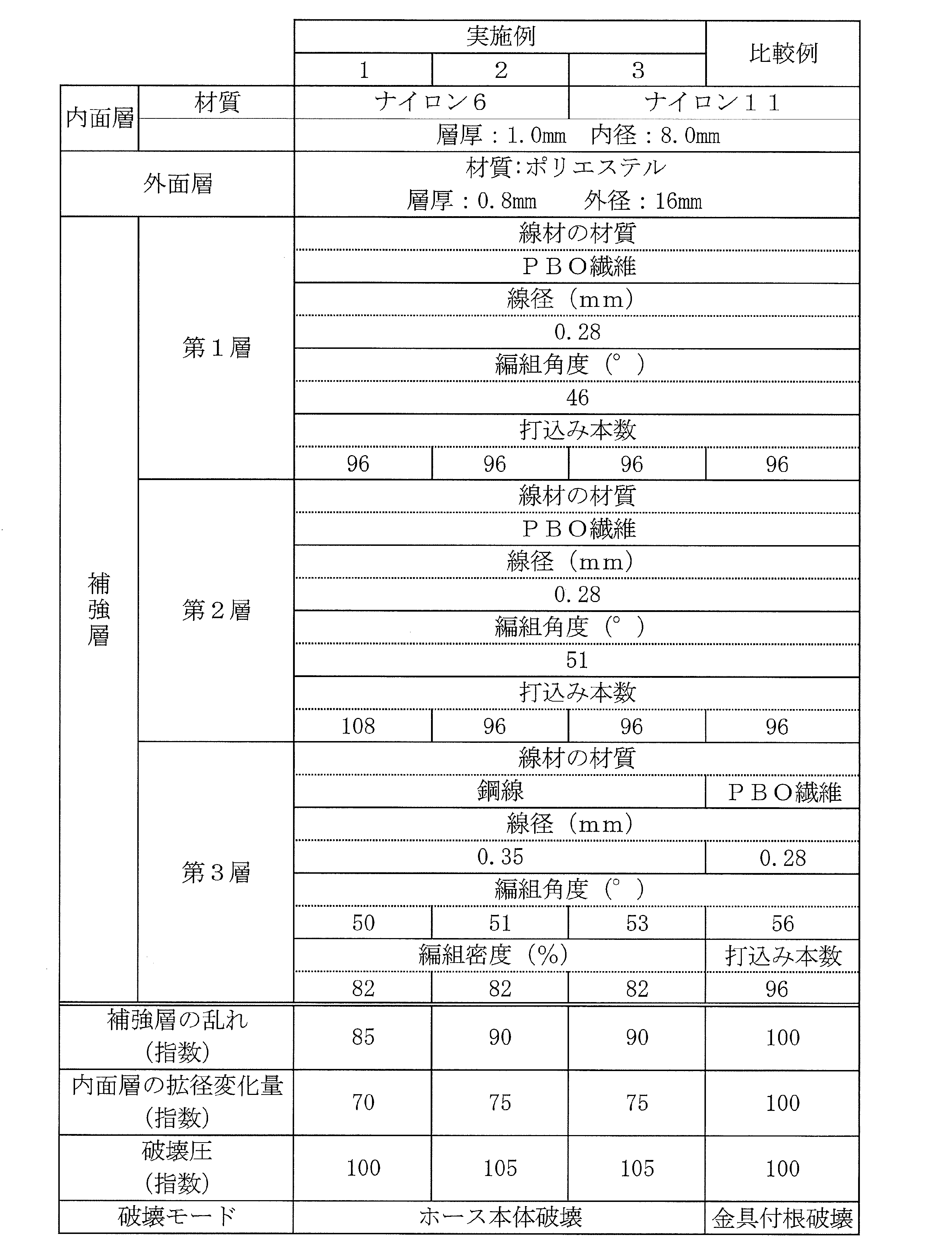
- Example 1 four types of analysis models having the same structure as the hose illustrated in FIG. 1 (Examples 1 to 3 and Comparative Examples) were produced by changing only the specifications of the reinforcing layer, and the disturbance of the reinforcing layer and the inner surface
- the amount of change in diameter expansion (size change) of the layer was analyzed and evaluated.
- the first layer in Table 1 means the innermost peripheral layer
- the second layer means a layer laminated on the outer peripheral surface of the first layer
- the third layer means the outermost peripheral layer.
- the gas permeability coefficient of dry hydrogen at 90 ° C. of the inner layer was 1 ⁇ 10 ⁇ 8 cc ⁇ cm / cm 2 ⁇ sec. -It is below cmHg.
- test samples were prepared for these four types, and the pressure resistance of the hose assembly in which hose fittings having the same specifications were crimped to the hose ends with the same crimping force was evaluated.
- the breaking pressure was measured in accordance with the method described in JIS K6330-2. These evaluation results are shown in Table 1.
- the burst pressure was evaluated as an index with a comparative example being 100 as a reference. The larger the index, the better the pressure resistance. The failure mode is also described.
- Hose fittings of the same specifications are attached to the end of the hose with the same caulking force and the blade structure is distorted in the outermost reinforcing layer when the internal pressure of the hose is 80 MPa (up / down fluctuation) was evaluated as an index using the comparative example as a standard of 100. A smaller index indicates less disturbance.
- Example 2 in addition to the above-described test sample (Example 3) in which the reinforcing layer was the first fiber blade layer, the second fiber blade layer, and the wire blade layer from the inner peripheral side, Three types of test samples (Examples 4 to 6) in which only the specification of the reinforcing layer was changed as shown in Table 2 were made into one fiber blade layer, second fiber blade layer, third fiber blade layer, and wire blade layer.
- the pressure resistance of the hose assembly in which hose fittings with the same specifications are crimped to the end of the hose with the same crimping force and the dimensional change (length change when the hose is pressurized) Rate and outer diameter change rate) and the inner diameter layer expansion change.
- the gas permeability coefficient of dry hydrogen at 90 ° C. of the inner layer was 1 ⁇ 10 ⁇ 8 cc ⁇ cm / cm 2 ⁇ sec. -It was below cmHg.
- the breaking pressure was measured in accordance with the method described in JIS K6330-2. These evaluation results are shown in Table 2. Each evaluation result was evaluated as an index using Example 3 as a standard of 100. The larger the index, the better the pressure resistance, and the smaller the index, the smaller the dimensional change rate and the diameter expansion change amount.
- Examples 4 to 6 are superior in pressure resistance compared to Example 3, dimensional changes (length change rate and outer diameter change rate) when the hose is pressurized, and inner layer diameter change. You can see that the amount is small.
- the change in diameter expansion (distortion) of the inner surface layer during pressurization of the hose is suppressed, the hose life span becomes longer, and if the change in diameter expansion of the inner surface layer is reduced by about 30%, the hose life span becomes 1 It was also possible to grasp that it was more than 5 times. Therefore, according to Examples 4 to 6, the hose life time is significantly improved as compared with Example 3.
Landscapes
- Engineering & Computer Science (AREA)
- General Engineering & Computer Science (AREA)
- Mechanical Engineering (AREA)
- Manufacturing & Machinery (AREA)
- Textile Engineering (AREA)
- Rigid Pipes And Flexible Pipes (AREA)
- Laminated Bodies (AREA)
Abstract
Description
同一仕様のホース金具を同一加締め力でホース端部に加締めて取り付け、ホース内圧を80MPaにした場合の最外周の補強層の加締められた部分のブレード構造の乱れ具合(上下変動量)を、比較例を基準の100として指数評価した。指数が小さい程、乱れ具合が少ないことを示す。
上記の補強層の乱れの評価と同じ条件下における内面層の内径の拡径変化量を、比較例を基準の100として指数評価した。指数が小さい程、拡径変化量が少ないことを示す。

2 内面層
3 補強層
3a 第1繊維ブレード層
3b 第2繊維ブレード層
3c 第3繊維ブレード層
3m ワイヤブレード層
4 外面層
5 ディスペンサ
6 ホース金具
7 車両
f 高強度繊維
m 金属ワイヤ
CL ホース軸心
Claims (7)
- 同軸状に積層された内面層と外面層との間に、少なくとも2層の補強層が同軸状に積層され、前記内面層が90℃における乾燥水素ガスのガス透過係数が1×10⁻⁸cc・cm/cm2・sec.・cmHg以下の熱可塑性樹脂により形成され、前記外面層が熱可塑性樹脂により形成された水素充填用ホースにおいて、
前記補強層のうち最外周の補強層が金属ワイヤを編組して形成されたワイヤブレード層であり、その他の補強層が高強度繊維を編組して形成された繊維ブレード層であることを特徴とする水素充填用ホース。 - 前記内面層の層厚が0.5mm以上1.5mm以下であり、内径が5mm以上9mm以下である請求項1に記載の水素充填用ホース。
- 前記金属ワイヤの線径が0.25mm以上0.4mm以下であり、その編組角度が45°以上55°以下であり、前記ワイヤブレード層の編組密度が70%以上である請求項1または2に記載の水素充填用ホース。
- 前記繊維ブレード層が少なくとも2層であり、これら繊維ブレード層を構成する前記高強度繊維の線径が0.25mm以上0.30mm以下であり、最内周の繊維ブレード層の編組角度が45°以上55°以下であり、2番目に内周側の繊維ブレード層の編組角度が50°以上60°以下である請求項1~3のいずれかに記載の水素充填用ホース。
- 前記金属ワイヤの線径が0.25mm以上0.4mm以下であり、その編組角度が55°超60°以下であり、前記ワイヤブレード層の編組密度が70%以上である請求項1または2に記載の水素充填用ホース。
- 前記繊維ブレード層が少なくとも3層であり、これら繊維ブレード層を構成する前記高強度繊維の線径が0.25mm以上0.30mm以下であり、最内周の繊維ブレード層の編組角度が43°以上55°以下であり、2番目に内周側の繊維ブレード層の編組角度が45°以上55°以下であり、3番目に内周側の繊維ブレード層の編組角度が50°以上60°以下である請求項1、2または5のいずれかに記載の水素充填用ホース。
- 前記高強度繊維がポリパラフェニレンベンズビスオキサゾール(PBO)繊維である請求項1~6のいずれかに記載の水素充填用ホース。
Priority Applications (3)
| Application Number | Priority Date | Filing Date | Title |
|---|---|---|---|
| EP16807350.0A EP3309438B1 (en) | 2015-06-09 | 2016-06-01 | Hydrogen-dispensing hose |
| US15/579,912 US10584810B2 (en) | 2015-06-09 | 2016-06-01 | Hydrogen-dispensing hose |
| KR1020177033791A KR102012885B1 (ko) | 2015-06-09 | 2016-06-01 | 수소 충전용 호스 |
Applications Claiming Priority (4)
| Application Number | Priority Date | Filing Date | Title |
|---|---|---|---|
| JP2015116763 | 2015-06-09 | ||
| JP2015-116763 | 2015-06-09 | ||
| JP2016-020574 | 2016-02-05 | ||
| JP2016020574A JP6103088B2 (ja) | 2015-06-09 | 2016-02-05 | 水素充填用ホース |
Publications (1)
| Publication Number | Publication Date |
|---|---|
| WO2016199643A1 true WO2016199643A1 (ja) | 2016-12-15 |
Family
ID=57503961
Family Applications (1)
| Application Number | Title | Priority Date | Filing Date |
|---|---|---|---|
| PCT/JP2016/066230 WO2016199643A1 (ja) | 2015-06-09 | 2016-06-01 | 水素充填用ホース |
Country Status (2)
| Country | Link |
|---|---|
| EP (1) | EP3309438B1 (ja) |
| WO (1) | WO2016199643A1 (ja) |
Cited By (1)
| Publication number | Priority date | Publication date | Assignee | Title |
|---|---|---|---|---|
| US11085560B2 (en) | 2017-05-16 | 2021-08-10 | The Yokohama Rubber Co., Ltd. | High-pressure hose |
Families Citing this family (3)
| Publication number | Priority date | Publication date | Assignee | Title |
|---|---|---|---|---|
| FR3099409B1 (fr) * | 2019-07-30 | 2021-10-01 | Arkema France | Structure multicouche pour le transport ou le stockage de l’hydrogene |
| FR3114768B1 (fr) * | 2020-10-01 | 2023-09-29 | Arkema France | Structure multicouche pour le transport ou le stockage de l’hydrogene |
| DE102022213894A1 (de) | 2022-12-19 | 2024-06-20 | Contitech Deutschland Gmbh | Armatur zum Anschließen eines Schlauches, insbesondere für Hoch-druck-Wasserstoff-Fluidleitungen |
Citations (7)
| Publication number | Priority date | Publication date | Assignee | Title |
|---|---|---|---|---|
| JPS4912260Y1 (ja) * | 1970-09-18 | 1974-03-26 | ||
| JPS544090B2 (ja) * | 1975-05-01 | 1979-03-02 | ||
| JPS62108685U (ja) * | 1985-12-26 | 1987-07-11 | ||
| JPH0380095B2 (ja) * | 1981-09-14 | 1991-12-20 | Parker Hannifin Corp | |
| JPH11141751A (ja) * | 1997-09-05 | 1999-05-28 | Yokohama Rubber Co Ltd:The | 高圧ゴムホース |
| JP2010031993A (ja) * | 2008-07-30 | 2010-02-12 | Yokohama Rubber Co Ltd:The | 水素充填用ホース |
| WO2011067798A1 (en) * | 2009-12-04 | 2011-06-09 | Errecinque S.R.L | Multi -layer tube, in particular for transporting gases in liquid state |
Family Cites Families (1)
| Publication number | Priority date | Publication date | Assignee | Title |
|---|---|---|---|---|
| JPH0914518A (ja) * | 1995-04-28 | 1997-01-17 | Yokohama Rubber Co Ltd:The | 補強高圧ホース |
-
2016
- 2016-06-01 WO PCT/JP2016/066230 patent/WO2016199643A1/ja active Application Filing
- 2016-06-01 EP EP16807350.0A patent/EP3309438B1/en active Active
Patent Citations (7)
| Publication number | Priority date | Publication date | Assignee | Title |
|---|---|---|---|---|
| JPS4912260Y1 (ja) * | 1970-09-18 | 1974-03-26 | ||
| JPS544090B2 (ja) * | 1975-05-01 | 1979-03-02 | ||
| JPH0380095B2 (ja) * | 1981-09-14 | 1991-12-20 | Parker Hannifin Corp | |
| JPS62108685U (ja) * | 1985-12-26 | 1987-07-11 | ||
| JPH11141751A (ja) * | 1997-09-05 | 1999-05-28 | Yokohama Rubber Co Ltd:The | 高圧ゴムホース |
| JP2010031993A (ja) * | 2008-07-30 | 2010-02-12 | Yokohama Rubber Co Ltd:The | 水素充填用ホース |
| WO2011067798A1 (en) * | 2009-12-04 | 2011-06-09 | Errecinque S.R.L | Multi -layer tube, in particular for transporting gases in liquid state |
Non-Patent Citations (1)
| Title |
|---|
| See also references of EP3309438A4 * |
Cited By (1)
| Publication number | Priority date | Publication date | Assignee | Title |
|---|---|---|---|---|
| US11085560B2 (en) | 2017-05-16 | 2021-08-10 | The Yokohama Rubber Co., Ltd. | High-pressure hose |
Also Published As
| Publication number | Publication date |
|---|---|
| EP3309438A4 (en) | 2019-01-16 |
| EP3309438A1 (en) | 2018-04-18 |
| EP3309438B1 (en) | 2022-02-23 |
Similar Documents
| Publication | Publication Date | Title |
|---|---|---|
| JP6103088B2 (ja) | 水素充填用ホース | |
| EP3627026B1 (en) | High-pressure hose | |
| WO2016199643A1 (ja) | 水素充填用ホース | |
| JP6926413B2 (ja) | ホース | |
| JP2005282703A (ja) | 金属蛇腹管複合ホース | |
| JP6152887B2 (ja) | 高圧ホース | |
| JP5647392B2 (ja) | 水素充填用ホース | |
| JP2004150606A (ja) | 蛇腹金属管付ホース | |
| WO2012115224A1 (ja) | 樹脂製フューエルインレットパイプおよびその製法 | |
| JP5549247B2 (ja) | 水素充填用ホースとホース金具のアッセンブリ品の製造方法 | |
| JP6152886B2 (ja) | 水素充填用ホース | |
| JP6720826B2 (ja) | 水素充填用ホース | |
| EP3233469B1 (en) | Low extractable curb pump hose | |
| JP2007333183A (ja) | 液圧回路の衝撃圧吸収装置 | |
| JP2005282702A (ja) | 金属蛇腹管複合ホース | |
| JP2018031397A (ja) | ホース | |
| CN113710944A (zh) | 全橡胶低硫和提取的ped软管 | |
| JP7356009B2 (ja) | 水素充填用ホース | |
| CN217927610U (zh) | 一种管路连接组件及车辆 | |
| KR20230140907A (ko) | 하이브리드 보강층을 갖는 고압호스 | |
| JP2019194487A (ja) | 水素充填用ホース | |
| JP2006266349A (ja) | 高圧ゴムホース | |
| JP2002174369A (ja) | フレキシブル不透過膜及び不透過性ホース |
Legal Events
| Date | Code | Title | Description |
|---|---|---|---|
| 121 | Ep: the epo has been informed by wipo that ep was designated in this application |
Ref document number: 16807350 Country of ref document: EP Kind code of ref document: A1 |
|
| ENP | Entry into the national phase |
Ref document number: 20177033791 Country of ref document: KR Kind code of ref document: A |
|
| WWE | Wipo information: entry into national phase |
Ref document number: 15579912 Country of ref document: US |
|
| NENP | Non-entry into the national phase |
Ref country code: DE |
|
| WWE | Wipo information: entry into national phase |
Ref document number: 2016807350 Country of ref document: EP |