WO2016199613A1 - バーナ、燃焼装置、ボイラ及びバーナの制御方法 - Google Patents
バーナ、燃焼装置、ボイラ及びバーナの制御方法 Download PDFInfo
- Publication number
- WO2016199613A1 WO2016199613A1 PCT/JP2016/065929 JP2016065929W WO2016199613A1 WO 2016199613 A1 WO2016199613 A1 WO 2016199613A1 JP 2016065929 W JP2016065929 W JP 2016065929W WO 2016199613 A1 WO2016199613 A1 WO 2016199613A1
- Authority
- WO
- WIPO (PCT)
- Prior art keywords
- gas
- containing gas
- flow
- nozzle
- oxygen
- Prior art date
Links
Images


Classifications
-
- F—MECHANICAL ENGINEERING; LIGHTING; HEATING; WEAPONS; BLASTING
- F23—COMBUSTION APPARATUS; COMBUSTION PROCESSES
- F23D—BURNERS
- F23D1/00—Burners for combustion of pulverulent fuel
- F23D1/005—Burners for combustion of pulverulent fuel burning a mixture of pulverulent fuel delivered as a slurry, i.e. comprising a carrying liquid
-
- F—MECHANICAL ENGINEERING; LIGHTING; HEATING; WEAPONS; BLASTING
- F23—COMBUSTION APPARATUS; COMBUSTION PROCESSES
- F23C—METHODS OR APPARATUS FOR COMBUSTION USING FLUID FUEL OR SOLID FUEL SUSPENDED IN A CARRIER GAS OR AIR
- F23C7/00—Combustion apparatus characterised by arrangements for air supply
- F23C7/008—Flow control devices
-
- F—MECHANICAL ENGINEERING; LIGHTING; HEATING; WEAPONS; BLASTING
- F23—COMBUSTION APPARATUS; COMBUSTION PROCESSES
- F23D—BURNERS
- F23D1/00—Burners for combustion of pulverulent fuel
-
- F—MECHANICAL ENGINEERING; LIGHTING; HEATING; WEAPONS; BLASTING
- F23—COMBUSTION APPARATUS; COMBUSTION PROCESSES
- F23L—SUPPLYING AIR OR NON-COMBUSTIBLE LIQUIDS OR GASES TO COMBUSTION APPARATUS IN GENERAL ; VALVES OR DAMPERS SPECIALLY ADAPTED FOR CONTROLLING AIR SUPPLY OR DRAUGHT IN COMBUSTION APPARATUS; INDUCING DRAUGHT IN COMBUSTION APPARATUS; TOPS FOR CHIMNEYS OR VENTILATING SHAFTS; TERMINALS FOR FLUES
- F23L7/00—Supplying non-combustible liquids or gases, other than air, to the fire, e.g. oxygen, steam
- F23L7/007—Supplying oxygen or oxygen-enriched air
-
- F—MECHANICAL ENGINEERING; LIGHTING; HEATING; WEAPONS; BLASTING
- F23—COMBUSTION APPARATUS; COMBUSTION PROCESSES
- F23N—REGULATING OR CONTROLLING COMBUSTION
- F23N1/00—Regulating fuel supply
- F23N1/02—Regulating fuel supply conjointly with air supply
- F23N1/022—Regulating fuel supply conjointly with air supply using electronic means
-
- F—MECHANICAL ENGINEERING; LIGHTING; HEATING; WEAPONS; BLASTING
- F23—COMBUSTION APPARATUS; COMBUSTION PROCESSES
- F23D—BURNERS
- F23D2201/00—Burners adapted for particulate solid or pulverulent fuels
- F23D2201/10—Nozzle tips
-
- F—MECHANICAL ENGINEERING; LIGHTING; HEATING; WEAPONS; BLASTING
- F23—COMBUSTION APPARATUS; COMBUSTION PROCESSES
- F23D—BURNERS
- F23D2201/00—Burners adapted for particulate solid or pulverulent fuels
- F23D2201/20—Fuel flow guiding devices
-
- F—MECHANICAL ENGINEERING; LIGHTING; HEATING; WEAPONS; BLASTING
- F23—COMBUSTION APPARATUS; COMBUSTION PROCESSES
- F23D—BURNERS
- F23D2208/00—Control devices associated with burners
-
- F—MECHANICAL ENGINEERING; LIGHTING; HEATING; WEAPONS; BLASTING
- F23—COMBUSTION APPARATUS; COMBUSTION PROCESSES
- F23D—BURNERS
- F23D2209/00—Safety arrangements
- F23D2209/20—Flame lift-off / stability
-
- F—MECHANICAL ENGINEERING; LIGHTING; HEATING; WEAPONS; BLASTING
- F23—COMBUSTION APPARATUS; COMBUSTION PROCESSES
- F23D—BURNERS
- F23D2900/00—Special features of, or arrangements for burners using fluid fuels or solid fuels suspended in a carrier gas
- F23D2900/00016—Preventing or reducing deposit build-up on burner parts, e.g. from carbon
-
- F—MECHANICAL ENGINEERING; LIGHTING; HEATING; WEAPONS; BLASTING
- F23—COMBUSTION APPARATUS; COMBUSTION PROCESSES
- F23D—BURNERS
- F23D2900/00—Special features of, or arrangements for burners using fluid fuels or solid fuels suspended in a carrier gas
- F23D2900/14—Special features of gas burners
- F23D2900/14481—Burner nozzles incorporating flow adjusting means
-
- Y—GENERAL TAGGING OF NEW TECHNOLOGICAL DEVELOPMENTS; GENERAL TAGGING OF CROSS-SECTIONAL TECHNOLOGIES SPANNING OVER SEVERAL SECTIONS OF THE IPC; TECHNICAL SUBJECTS COVERED BY FORMER USPC CROSS-REFERENCE ART COLLECTIONS [XRACs] AND DIGESTS
- Y02—TECHNOLOGIES OR APPLICATIONS FOR MITIGATION OR ADAPTATION AGAINST CLIMATE CHANGE
- Y02E—REDUCTION OF GREENHOUSE GAS [GHG] EMISSIONS, RELATED TO ENERGY GENERATION, TRANSMISSION OR DISTRIBUTION
- Y02E20/00—Combustion technologies with mitigation potential
- Y02E20/34—Indirect CO2mitigation, i.e. by acting on non CO2directly related matters of the process, e.g. pre-heating or heat recovery
Definitions
- the present disclosure relates to a burner, a combustion apparatus, a boiler, and a burner control method.
- a burner for burning solid powder fuel is generally provided with a fuel supply nozzle through which an air-fuel mixture containing solid powder fuel and a carrier gas flows, and a fuel supply nozzle, and an oxygen-containing gas for combustion flows therethrough. And a gas flow path.
- a burner of this type in the combustion burner disclosed in Patent Document 1, an internal flame holding air nozzle is provided as a means for flowing a high-temperature gas near the outer periphery of the tip of the fuel supply nozzle into the mixed fluid.
- An air jet is ejected from the jet port of the internal flame-holding air nozzle toward the center of the air-fuel mixture nozzle.
- the air jet has a companion effect, and a part of the recirculated hot gas flows into the mixed gas flow along the air jet, and the ignition flame holding performance inside thereof is enhanced. Moreover, since the turbulence of the mixed gas flow is increased by the air jet, it is effective for improving the combustion efficiency after ignition.
- an internal flame-holding air nozzle is employed as a means for flowing a high-temperature gas in the vicinity of the outer periphery of the tip of the air-fuel mixture nozzle into the mixed fluid.
- the structure of the combustion burner becomes complicated and an internal flame holding air supply system needs to be added.
- an object of at least one embodiment of the present invention is to provide a burner, a combustion apparatus, a boiler, and a burner control method capable of stabilizing ignition and flame holding in an internal flame holding region with a simple configuration. There is to do.
- a burner comprises: An inner gas nozzle extending along the axis while enclosing the axis, and capable of supplying an oxygen-containing gas for inner combustion to the furnace; A fuel supply nozzle that surrounds the inner gas nozzle when viewed in the direction along the axis, and is capable of supplying a mixed fluid of solid powder fuel and carrier gas to the furnace; An outer gas nozzle that surrounds the fuel supply nozzle when viewed in a direction along the axis, and is capable of supplying an oxygen-containing gas for outer combustion to the furnace; A flow rate ratio adjusting mechanism capable of adjusting a relative flow rate ratio of the jet velocity of the inner combustion oxygen-containing gas and the jet velocity of the outer combustion oxygen-containing gas; A flame-holding region is formed on the jet flow side of the inner combustion oxygen-containing gas and the jet flow side of the outer combustion oxygen-containing gas in the jet flow of the mixed fluid downstream from the outlet of the fuel supply nozzle. It is comprised so that.
- An inner circulation vortex is formed between the jet flow of the mixed fluid jetted from the fuel supply nozzle and the jet flow of the inner combustion oxygen-containing gas. If the inner circulation vortex is strengthened, the flow rate of the inner hot gas circulation flow toward the fuel supply nozzle is increased by the inner circulation vortex, and the heat of the inner hot gas circulation flow increases the internal retention of the inner combustion oxygen-containing gas ejection flow side. It is possible to stabilize the ignition and flame holding in the flame area. On the other hand, an outer circulation vortex is formed between the jet flow of the mixed fluid jetted from the fuel supply nozzle and the jet flow of the oxygen-containing gas for outer combustion.
- the flow rate of the outer hot gas circulation flow toward the fuel supply nozzle is increased by the outer circulation vortex, and the heat of the outer hot gas circulation flow increases the external retention of the outer combustion oxygen-containing gas jet stream. It is possible to stabilize the ignition and flame holding in the flame area.
- the external flame holding area is more stable in ignition and flame holding due to radiation from the surroundings than the internal flame holding area, and stabilization of ignition and flame holding in each of the internal flame holding area and the external flame holding area.
- the jet velocity of the inner combustion oxygen-containing gas and the jet velocity of the outer combustion oxygen-containing gas required for the above are not necessarily the same.
- the internal flow rate adjustment mechanism adjusts the relative flow rate ratio of the flow rate of the inner combustion oxygen-containing gas and the flow rate of the outer combustion oxygen-containing gas to adjust the internal flow rate. It is possible to stabilize ignition and flame holding in each of the flame holding area and the external flame holding area.
- the burner according to at least one embodiment of the present invention is: An inner gas nozzle extending along the axis while enclosing the axis, and capable of supplying an oxygen-containing gas for inner combustion to the furnace; A fuel supply nozzle that surrounds the inner gas nozzle when viewed in the direction along the axis, and is capable of supplying a mixed fluid of solid powder fuel and carrier gas to the furnace; An outer gas nozzle that surrounds the fuel supply nozzle when viewed in a direction along the axis, and is capable of supplying an oxygen-containing gas for outer combustion to the furnace; An internal flame holder arranged at the outlet of the inner gas nozzle and configured to restrict the flow of the inner combustion oxygen-containing gas; An external flame holder arranged at the outlet of the outer gas nozzle and configured to deviate the flow of the outer combustion oxygen-containing gas from the axis; A flow rate ratio adjusting mechanism capable of adjusting a relative flow rate ratio between the jet velocity of the inner combustion oxygen-containing gas and the jet velocity of the outer combustion oxygen-containing gas
- the flow of the inner combustion oxygen-containing gas is restricted by the internal flame stabilizer, so that an inner circulation vortex is formed between the jet flow of the inner combustion oxygen-containing gas and the jet flow of the mixed fluid.
- the flow of the outer combustion oxygen-containing gas is expanded by the outside flame stabilizer deviating from the axis of the outer combustion oxygen-containing gas jet flow, and the outer combustion oxygen-containing gas jet flow and the mixed fluid jet flow An outer circulation vortex is easily formed between the two. Thereby, it is possible to stabilize the ignition and flame holding in each of the internal flame holding region and the external flame holding region.
- a plurality of intermediate flame stabilizers each extending between the outlet portion of the inner gas nozzle and the outlet portion of the outer gas nozzle so as to cross the outlet portion of the fuel supply nozzle.
- the intermediate flame holder extends so as to cross the outlet portion of the fuel supply nozzle, and the high-temperature gas flows along the intermediate flame holder from the external flame holding region to the internal flame holding region. be able to. Thereby, the temperature of the internal flame holding region can be raised, and ignition of the internal flame holding region and stabilization of the flame holding can be further achieved.
- the jet velocity of the inner combustion oxygen-containing gas is configured to be faster than the jet velocity of the outer combustion oxygen-containing gas.
- the pressure in the internal flame holding region is made lower than the pressure in the external flame holding region because the jet velocity of the inner combustion oxygen-containing gas is faster than the jet velocity of the outer combustion oxygen-containing gas. Therefore, the high-temperature gas flowing from the external flame holding region toward the internal flame holding region can easily flow, and ignition of the internal flame holding region and stabilization of the flame holding can be reliably achieved.
- the outer gas nozzle has two or more outer gas flow paths each surrounding the fuel supply nozzle as seen in the direction along the axis,
- the outer combustion oxygen-containing gas can be supplied to the furnace through the two or more outer gas passages.
- the configuration (5) by supplying the oxygen-containing gas for outer combustion through two or more outer gas flow paths, the flow rate and direction of the oxygen-containing gas for outer combustion can be distributed, and the internal flame holding region In addition, it is possible to further stabilize the ignition and flame holding in each of the external flame holding regions.
- the apparatus further includes an outer gas flow controller disposed in at least one of the two or more outer gas flow paths.
- the flow rate of the outer combustion oxygen-containing gas flowing out from the outer gas flow path in which the outer gas flow rate controller is disposed can be adjusted by the outer gas flow rate controller, It is possible to further stabilize the ignition and flame holding of each external flame holding region.
- the inner gas nozzle has two or more inner gas flow paths each surrounding the axis when viewed in the direction along the axis.
- a flow rate regulator capable of adjusting a flow rate of the inner combustion oxygen-containing gas flowing through the innermost combustion gas supply flow channel located in the innermost side in the direction along the axis among the two or more inner gas flow channels;
- the reduced state is maintained in the internal flame holding region regardless of the properties of the solid powder fuel by adjusting the flow rate of the inner combustion oxygen-containing gas flowing through the innermost combustion gas supply passage. And generation of NOx can be suppressed.
- the apparatus further includes a control device capable of automatically controlling the flow rate ratio adjusting mechanism.
- a control device capable of automatically controlling the flow rate ratio adjusting mechanism.
- a pressure sensor provided at the outlet of the inner gas nozzle or the outlet of the outer gas nozzle;
- the control device can control the flow rate ratio adjusting mechanism based on the output of the pressure sensor.
- the control device controls the flow rate ratio adjusting mechanism based on the output of the pressure sensor, so that ignition and stabilization of each of the internal flame holding region and the external flame holding region can be easily and reliably performed. I can plan.
- An internal flame stabilizer arranged at the outlet of the inner gas nozzle to restrict the flow of the inner combustion oxygen-containing gas, and the flow of the outer combustion oxygen-containing gas arranged at the outlet of the outer gas nozzle
- An external flame holder configured to deviate from the axis, and a plurality of intermediate portions respectively extending between the outlet portion of the inner gas nozzle and the outlet portion of the outer gas nozzle so as to cross the outlet portion of the fuel supply nozzle At least one of the flame holders;
- a guide member capable of guiding at least a portion of the inner combustion oxygen-containing gas, the outer combustion oxygen-containing gas, or the mixed fluid so as to flow along the furnace side surface of the at least one flame stabilizer; .
- the inner combustion oxygen-containing gas and the outer combustion are caused by the guide member along the furnace side surface of at least one of the internal flame holder, the external flame holder, and the intermediate flame holder.
- the oxygen-containing gas or the mixed fluid By flowing a part of the oxygen-containing gas or the mixed fluid, at least one flame holder can be cooled, and ash adhesion to the flame holder can be suppressed.
- a combustion apparatus includes: With a wind box, The burner according to any one of the configurations (1) to (10) covered with the wind box.
- the combustion apparatus having the above configuration (11) employs any one of the burners according to the above configurations (1) to (10), thereby stabilizing ignition and flame holding in each of the internal flame holding region and the external flame holding region. Can be planned.
- a boiler according to at least one embodiment of the present invention A furnace, A wind box attached to the furnace; The burner according to any one of the configurations (1) to (10), which is attached to the furnace and covered with the wind box.
- the boiler of the above configuration (12) employs any one of the burners of the above configurations (1) to (10) to stabilize ignition and flame holding in each of the internal flame holding region and the external flame holding region. I can plan.
- a burner control method includes: An inner gas nozzle extending along the axis while enclosing the axis, and capable of supplying an oxygen-containing gas for inner combustion to the furnace; A fuel supply nozzle that surrounds the inner gas nozzle when viewed in the direction along the axis, and is capable of supplying a mixed fluid of solid powder fuel and carrier gas to the furnace; An outer gas nozzle that surrounds the fuel supply nozzle when viewed in a direction along the axis, and is capable of supplying an oxygen-containing gas for outer combustion to the furnace; A flow rate ratio adjusting mechanism capable of adjusting a relative flow rate ratio of the jet velocity of the inner combustion oxygen-containing gas and the jet velocity of the outer combustion oxygen-containing gas; A flame-holding region is formed on the jet flow side of the inner combustion oxygen-containing gas and the jet flow side of the outer combustion oxygen-containing gas in the mixed fluid downstream from the outlet of the fuel supply nozzle, respectively.
- the inner gas nozzle has two or more inner gas flow paths each surrounding the axis when viewed in the direction along the axis.
- a flow rate regulator capable of adjusting a flow rate of the inner combustion oxygen-containing gas flowing through the innermost combustion gas supply flow channel located in the innermost side in the direction along the axis among the two or more inner gas flow channels;
- a burner control method further comprising: When the fuel ratio of the solid powder fuel exceeds a threshold value, the opening degree of the flow controller is set smaller than when the fuel ratio of the solid powder fuel is equal to or less than the threshold value.
- the opening degree of the flow rate controller is set smaller than when the fuel ratio of the solid powder fuel is equal to or less than the threshold value.
- the flow rate (total flow rate) of the inner combustion oxygen-containing gas can be reduced while maintaining the jet velocity of the inner combustion oxygen-containing gas.
- the internal flame holding region can be maintained and NOx generation can be suppressed.
- An outer gas flow controller capable of adjusting the flow rate of the outer combustion oxygen-containing gas; When the fuel ratio of the solid powder fuel exceeds the threshold value, the opening degree of the outer gas flow controller is set larger than when the fuel ratio of the solid powder fuel is equal to or less than the threshold value.
- the outer combustion is performed by setting the opening degree of the outer gas flow controller larger than that when the fuel ratio of the solid powder fuel is equal to or less than the threshold value.
- An increase in the flow velocity of the oxygen-containing gas for use can be suppressed.
- the difference between the jetting flow rate of the outer combustion oxygen-containing gas and the jetting flow rate of the inner combustion oxygen-containing gas is ensured, and the internal flame holding region can be maintained more reliably and NOx generation can be suppressed.
- the outer gas nozzle has two or more outer gas flow paths each surrounding the fuel supply nozzle as seen in the direction along the axis,
- the outer combustion oxygen-containing gas can be supplied to the furnace through the two or more outer gas flow paths.
- the outer gas flow controller can adjust the flow rate of the outer combustion oxygen-containing gas in the outermost outer gas flow path, When the fuel ratio of the solid powder fuel exceeds the threshold value, the opening degree of the outer gas flow controller is set larger than when the fuel ratio of the solid powder fuel is equal to or less than the threshold value.
- the opening degree of the outer gas flow controller is set larger than when the fuel ratio of the solid powder fuel is less than or equal to the threshold, and conversely, when the fuel ratio of the solid powder fuel is less than or equal to the threshold, The opening degree of the outer gas flow controller is set smaller than when the fuel ratio of the solid powder fuel exceeds the threshold value.
- the opening degree of the outer gas flow controller is set to be small, so that the outer flow rate of the oxygen-containing gas for outer combustion is reduced even if the total flow rate of the outer combustion oxygen-containing gas is reduced.
- the ejection flow rate of the oxygen-containing gas for combustion can be maintained. As a result, the outer circulation vortex is prevented from being weakened, and the stability of ignition and flame holding in the external flame holding region is ensured.
- a burner capable of stabilizing ignition and flame holding in an internal flame holding region with a simple configuration.
- FIG. 14 is a schematic cross-sectional view taken along line XIV-XIV in FIG. 13. It is a flowchart which shows the schematic procedure of the control method of the burner which concerns on one Embodiment of this invention. It is a flowchart which shows the schematic procedure of the control method of the burner which concerns on other one Embodiment of this invention. It is a flowchart which shows the schematic procedure of the control method of the burner which concerns on other one Embodiment of this invention. It is a flowchart which shows the schematic procedure of the control method of the burner which concerns on other one Embodiment of this invention. It is a figure for demonstrating other one Embodiment which applied the control apparatus to the burner. It is a figure for demonstrating other one Embodiment which applied the control apparatus to the burner. It is a figure for demonstrating the modification of the burner of FIG.
- an expression indicating that things such as “identical”, “equal”, and “homogeneous” are in an equal state not only represents an exactly equal state, but also has a tolerance or a difference that can provide the same function. It also represents the existing state.
- expressions representing shapes such as quadrangular shapes and cylindrical shapes represent not only geometrically strict shapes such as quadrangular shapes and cylindrical shapes, but also irregularities and chamfers as long as the same effects can be obtained. A shape including a part or the like is also expressed.
- the expressions “comprising”, “comprising”, “comprising”, “including”, or “having” one constituent element are not exclusive expressions for excluding the existence of the other constituent elements.
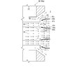
- FIG. 1 is a diagram schematically showing a configuration of a boiler 1 according to an embodiment of the present invention.
- the boiler 1 includes a furnace 5 and a combustion device 10 attached to the furnace 5.
- the combustion apparatus 10 can supply a solid powder fuel and an oxygen-containing gas to the furnace 5, and the high temperature gas (combustion gas) is generated when the solid powder fuel burns inside the furnace 5.
- the hot gas heats water as a heat medium via a heat exchanger such as a economizer, superheater, and reheater (not shown), and uses the steam obtained thereby, for example, turbine power generation (not shown).
- the machine can be activated.
- the solid powder fuel refers to a fine powder fuel obtained by pulverizing a simple substance or a mixture of coal, oil coke, solid biomass and the like.
- the combustion apparatus 10 includes at least one burner 20 that can be attached to the furnace 5, and a wind box 22 that can be attached to the furnace 5 so as to surround the burner 20.
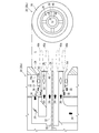
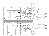
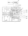
- FIG. 2 is a cross-sectional view and a front view schematically showing the burner 20 (20a) according to one embodiment of the present invention in a state where the burner 20 is attached to the furnace 5.
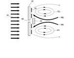
- FIG. 3 is a diagram for explaining the function of the burner 20a.
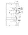
- FIGS. 4 and 5 are a cross-sectional view and a front view schematically showing a burner 20 (20b, 20c) according to another embodiment of the present invention attached to the furnace 5.
- FIG. FIG. 6 is a diagram for explaining the function of the burner 20c.
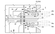
- 7 and 8 are cross-sectional views schematically showing a burner 20 (20d, 20e) according to another embodiment of the present invention attached to the furnace 5.
- FIG. FIG. 9 is a cross-sectional view and a front view schematically showing a burner 20 (20f) according to another embodiment of the present invention attached to the furnace 5.
- the burner 20 (20 a to 20 f) includes an inner gas nozzle 24, a fuel supply nozzle 26, an outer gas nozzle 28, and a flow rate ratio.
- the inner gas nozzle 24 extends along the axis 32 while surrounding the axis 32, and can supply the inner combustion oxygen-containing gas 34 to the furnace 5.
- the axis 32 may be orthogonal or inclined with respect to the outer wall of the furnace 5.
- the inner combustion oxygen-containing gas 34 is, for example, air.
- the combustion oxygen-containing gas is a mixed gas mainly composed of carbon dioxide and oxygen.
- the fuel supply nozzle 26 surrounds the inner gas nozzle 24 when viewed in the direction along the axis 32, and can supply a mixed fluid 36 of solid powder fuel and carrier gas to the furnace 5.
- the solid powder fuel is, for example, pulverized coal
- the carrier gas is, for example, air.
- the outer gas nozzle 28 surrounds the fuel supply nozzle 26 when viewed in the direction along the axis 32, and can supply the outer combustion oxygen-containing gas 38 to the furnace 5.
- the outer combustion oxygen-containing gas 38 is, for example, air.
- the flow rate ratio adjusting mechanism 30 can adjust the relative flow rate ratio between the jet flow velocity Fc of the inner combustion oxygen-containing gas 34 and the jet flow velocity Fo of the outer combustion oxygen-containing gas 38.
- the burner 20 is disposed downstream of the outlet of the fuel supply nozzle 26, on the inner combustion oxygen-containing gas 34 side and the outer combustion oxygen-containing gas 38 side of the jet flow of the mixed fluid 36, and the internal flame holding region 40a and Each of the external flame holding regions 40b is formed.
- the internal flame holding region 40a and the external flame holding region 40b are regions where solid powder fuel is ignited and burned.
- the internal flame holding area 40 a and the external flame holding area 40 b are formed immediately downstream of the outlet of the fuel supply nozzle 26.
- an outer circulation vortex 42 b is formed between the mixed fluid 36 ejected from the fuel supply nozzle 26 and the outer combustion oxygen-containing gas 38 ejected from the outer gas nozzle 28. If the outer circulation vortex 42b is strengthened, the outer circulation vortex 42b increases the flow rate of the hot gas flow (outer hot gas circulation flow 44b) toward the fuel supply nozzle 26, and the heat of the outer hot gas circulation flow 44b increases the outer flow. It is possible to stabilize ignition and flame holding in the external flame holding region 40b on the combustion oxygen-containing gas 38 side.
- the external flame holding region 40b is more stable in ignition and flame holding due to radiation from the surroundings than the internal flame holding region 40a, and the ignition and holding in each of the internal flame holding region 40a and the external flame holding region 40b.
- the ejection flow rate Fc of the inner combustion oxygen-containing gas 34 and the ejection flow rate Fo of the outer combustion oxygen-containing gas 38 that are necessary for stabilizing the flame do not necessarily match each other.
- the flow rate ratio adjusting mechanism 30 adjusts the relative flow rate ratio of the jet flow velocity Fc of the inner combustion oxygen-containing gas 34 and the jet flow velocity Fo of the outer combustion oxygen-containing gas 38.
- the inner gas nozzle 24, the fuel supply nozzle 26, and the outer gas nozzle 28 have a multi-tube structure.
- the inner gas nozzle 24 is constituted by a cylindrical member, and the inner combustion oxygen-containing gas 34 can flow inside the cylindrical member.
- the fuel supply nozzle 26 is constituted by two cylindrical members surrounding the inner gas nozzle 24, and the mixed fluid 36 can flow between the two cylindrical members.
- the outer gas nozzle 28 is constituted by two cylindrical members surrounding the fuel supply nozzle 26, and the outer combustion oxygen-containing gas 38 can flow between the two cylindrical members.
- the cylindrical member (outer wall) of the inner gas nozzle 24 and the cylindrical member (inner wall) inside the fuel supply nozzle 26 may be common or may be joined to each other.
- the cylindrical member (outer wall) outside the fuel supply nozzle 26 and the cylindrical member (inner wall) inside the outer gas nozzle 28 may be common or joined together.
- the cylindrical shape is not limited to the cylindrical shape as shown in FIGS. 2, 4, and 5, and includes a polygonal cylindrical shape as shown in FIG. 9.
- the burner 20 (20a-20f) may include an internal flame holder 46 and an external flame holder 48, as shown in FIGS. 2, 4, 5, and 7-9, respectively. Is further provided.
- the internal flame stabilizer 46 is disposed at the outlet of the inner gas nozzle 24 and is configured to restrict the flow of the inner combustion oxygen-containing gas 34.
- the external flame stabilizer 48 is disposed at the outlet of the outer gas nozzle 28 and is configured so that the flow of the outer combustion oxygen-containing gas 38 deviates from the axis 32.
- the inner combustion oxygen-containing gas 34 is throttled by the internal flame stabilizer 46, whereby the inner circulation vortex 42 a is formed between the jet flow of the inner combustion oxygen-containing gas 34 and the jet flow of the mixed fluid 36.
- the outer combustion oxygen-containing gas 38 is deviated from the axis 32 by the external flame stabilizer 48, so that the outer combustion oxygen-containing gas 38 spreads, and the jet flow of the outer combustion oxygen-containing gas 38 and the mixed fluid are expanded.
- the outer circulation vortex 42b is easily formed between the 36 jet flows. Thereby, the ignition and stabilization of each of the internal flame holding region 40a and the external flame holding region 40b can be achieved.
- the burner 20 further includes an internal flame holder 46 and an external flame holder 48, other configurations for forming the internal flame holding region 40a and the external flame holding region 40b for the burner 20 are as follows. Not required.
- the internal flame stabilizer 46 is constituted by a plate-shaped member extending inward from the periphery of the outlet portion of the inner gas nozzle 24.
- the external flame stabilizer 48 is configured by a plate-shaped member that extends outward from the periphery of the outlet portion of the outer gas nozzle 28.
- the inner side refers to the side close to the axis 32 in the direction (radial direction) intersecting the axis 32, and the outer refers to the side far from the axis 32.
- the flow rate ratio adjusting mechanism 30 is configured by a damper disposed in the flow path of the inner combustion oxygen-containing gas 34.
- the inlet of the flow path of the inner combustion oxygen-containing gas 34 opens into the wind box 22, and the outlet of the flow path of the inner combustion oxygen-containing gas 34 is constituted by the outlet of the inner gas nozzle 24.
- the inlet of the flow path of the outer combustion oxygen-containing gas 38 opens into the wind box 22, and the outlet of the flow path of the outer combustion oxygen-containing gas 38 is constituted by the outlet of the outer gas nozzle 28.
- the inlet of the inner combustion oxygen-containing gas 34 and the outer combustion oxygen-containing gas 38 are connected to the wind box 22 which is the same gas supply source.
- the damper disposed in the flow path of the oxygen-containing gas 34 ensures the relative flow rate of the injection flow rate Fc of the inner combustion oxygen-containing gas 34 and the injection flow rate Fo of the outer combustion oxygen-containing gas 38 with a simple configuration. The ratio can be adjusted.
- the burners 20b, 20c, 20d, and 20e further include a plurality of intermediate flame holders 50, as shown in FIGS.
- the plurality of intermediate flame stabilizers 50 extend between the outlet portion of the inner gas nozzle 24 and the outlet portion of the outer gas nozzle 28 so as to cross the outlet portion of the fuel supply nozzle 26.
- the plurality of intermediate flame holders 50 are separated from each other when viewed in the direction along the axis 32, and the mixed fluid 36 can be ejected from the fuel supply nozzle 26 through the intermediate flame holders 50.
- the intermediate flame holder 50 extends so as to cross the outlet of the fuel supply nozzle 26, and the intermediate flame holder 50b is moved from the external flame holding area 40b toward the internal flame holding area 40a. Hot gas can flow along the flame 50. Thereby, the temperature of the internal flame holding area 40a can be raised, and ignition of the internal flame holding area 40a and stabilization of flame holding can be further achieved.
- the intermediate flame stabilizer 50 is constituted by a plate-shaped member disposed so as to cross the outlet portion of the fuel supply nozzle 26.
- the burner 20 is configured such that the ejection flow rate Fc of the inner combustion oxygen-containing gas 34 is faster than the ejection flow rate Fo of the outer combustion oxygen-containing gas 38.
- the jetting flow rate Fc of the inner combustion oxygen-containing gas 34 is faster than the jetting flow rate Fo of the outer combustion oxygen-containing gas 38, so that the outer flame holding region 40b toward the inner flame holding region 40a.
- the flow rate of the flowing high-temperature gas increases, and the ignition of the internal flame holding region 40a and the stabilization of the flame holding can be reliably achieved.
- the outer gas nozzle 28 includes two or more outer gas passages 28 a, each surrounding the fuel supply nozzle 26 as viewed along the axis 32. 28b and 28c.
- the outer combustion oxygen-containing gas 38 is supplied to the furnace 5 through the two or more outer gas passages 28a, 28b, 28c.
- the outer combustion oxygen-containing gas 38 is supplied through the two or more outer gas flow paths 28a, 28b, and 28c, so that the outer combustion oxygen-containing gas 38 is distributed in the flow velocity and direction. Therefore, the ignition and stabilization of the internal flame holding region 40a and the external flame holding region 40b can be further improved.
- the two or more outer gas flow paths 28 a, 28 b, and 28 c can be formed by disposing one or more cylindrical members inside the outer gas nozzle 28.
- the burners 20c, 20d, 20e further comprise an outer gas flow regulator 52 disposed in at least one of the two or more outer gas flow paths 28a, 28b, 28c.
- the flow rate of the contained gas 38 can be adjusted. Thereby, it is possible to further stabilize the ignition and flame holding of each of the internal flame holding region 40a and the external flame holding region 40b.
- the outer gas flow controller 52 is configured by a movable vane or a damper.
- the two or more outer gas passages 28 a, 28 b, and 28 c are positioned on the fuel supply nozzle 26 side as viewed along the axis 32.
- the burners 20c, 20d, and 20e are installed at the outlet of the second outer gas passage 28b, and the flow of the outer combustion oxygen-containing gas 38 that has passed through the second outer gas passage 28b is gradually increased from the axis 32.
- a second outer gas guide plate 54 configured to deflect is further provided.
- the outer circulation vortex 42b is increased by the outer combustion oxygen-containing gas 38 that flows through the second outer gas passage 28b, and the ignition and stabilization of the outer flame holding region 40b are stabilized. You can plan even more. As the flow of the oxygen-containing gas 38 for outer combustion spreads, the reduction region over the internal flame holding region 40a and the external flame holding region 40b becomes large, and NOx generation is suppressed.
- the second outer gas guide plate 54 is constituted by a truncated cone-shaped member.
- the burners 20c, 20d, 20e further include a swivel imparting mechanism 56 disposed in the second outer gas flow path 28b.
- the outer circulation vortex 42b is increased by adding the swirl component to the outer combustion oxygen-containing gas 38 that flows through the second outer gas flow path 28b, and the outer flame holding region 40b. It is possible to further stabilize the ignition and flame holding. Further, by applying a swirl component to the outer combustion oxygen-containing gas 38 flowing through the second outer gas flow path 28b, the outer circulation vortex 42b is further expanded, and ignition of the external flame holding region 40b and stabilization of flame holding are further enhanced.
- the turning imparting mechanism 56 may be fixed or movable.
- the turning imparting mechanism 56 is configured by a fixed vane or a movable vane.
- the burner 20e further includes a swivel imparting mechanism 56 disposed in the third outer gas flow path 28c.
- FIG. 10 is a diagram for explaining another embodiment in which the control device 60 is applied to the burner 20.
- the burner 20 further comprises a controller 60, as shown in FIG.
- the control device 60 can automatically control the flow rate ratio adjusting mechanism 30.
- the flow rate ratio adjusting mechanism 30 is automatically controlled by the control device 60, so that the ignition and stabilization of each of the internal flame holding region 40a and the external flame holding region 40b can be easily and reliably performed. I can plan.
- the burner 20 further comprises pressure sensors 62a, 62b provided at the outlet of the inner gas nozzle 24 or the outlet of the outer gas nozzle 28, as shown in FIG.
- the control device 60 can control the flow rate ratio adjusting mechanism 30 based on the outputs of the pressure sensors 62a and 62b.
- the control device 60 controls the flow rate ratio adjusting mechanism 30 based on the outputs of the pressure sensors 62a and 62b, thereby stabilizing the ignition and flame holding of each of the internal flame holding region 40a and the external flame holding region 40b. Can be easily and reliably realized.
- control device 60 is configured by a computer.
- the control device 60 can control the flow rate ratio adjusting mechanism 30 via a drive device (not shown).
- the drive device is configured by, for example, an electromagnetic actuator or a hydraulic actuator.
- the burners 20c, 20d, and 20e further include a concentrator 66, as shown in FIGS.
- the concentrator 66 is disposed in the fuel supply nozzle 26, and is a solid powder fuel on the inner combustion oxygen-containing gas 34 side and the outer combustion oxygen-containing gas 38 side of the flow of the mixed fluid 36 at the outlet of the fuel supply nozzle 26.
- a region having a relatively high concentration is formed. That is, the concentrator 66 is configured so as to form a region where the concentration of the solid powder fuel is relatively higher inside and outside the flow of the mixed fluid 36 than between the inside and outside.
- the concentration region of the solid powder fuel can be formed on the inner combustion oxygen-containing gas 34 side and the outer combustion oxygen-containing gas 38 side by the concentrator 66. It is possible to further stabilize the ignition and flame holding of each of the flame region 40a and the external flame holding region 40b.
- the concentrator 66 is a member arranged to surround the inner wall of the fuel supply nozzle 26, between the inner wall and the outer wall of the fuel supply nozzle 26, and each of these inner and outer walls. It is comprised by the member arrange
- the mixed fluid 36 can be separated into the inner wall side and the outer wall side, and the solid powder fuel having a larger specific gravity than the carrier gas can be biased toward the inner wall side and the outer wall side.
- the concentrator 66 is composed of an annular member and is supported by a support member (not shown).
- FIG. 11 is a view for explaining a configuration of a guide member 70 applicable to the burner 20.
- the guide member 70 is configured to guide at least a part of the inner combustion oxygen-containing gas 34 so as to flow along the furnace 5 side surface of the internal flame stabilizer 46.
- the internal flame holder 46 can be cooled and the internal flame holder 46 can be cooled by flowing a part of the inner combustion oxygen-containing gas 34 along the surface of the internal flame holder 46 on the furnace 5 side. The ash adhesion to the flame holder 46 can be suppressed.
- the guide member 70 is configured by an annular flange projecting inward from the opening edge of the outlet portion of the fuel supply nozzle 26.
- the internal flame holder 46 is constituted by an annular plate and is disposed inside the outlet portion of the fuel supply nozzle 26.
- the internal flame stabilizer 46 is supported by, for example, a support member 71 in a state of protruding inward from the guide member 70.
- a gap 72 is secured between the internal flame holder 46 and the inner wall of the fuel supply nozzle 26, and a gap 73 is secured between the internal flame holder 46 and the guide member 70.
- a part of the inner combustion oxygen-containing gas 34 flows through the gaps 72 and 73 and can flow along the furnace 5 side surface of the internal flame holder 46.
- the expression “annular shape” includes a polygonal shape in addition to a circular shape.
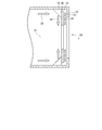
- FIG. 12 is a view for explaining the configuration of the guide member 76 applicable to the burner 20.
- the guide member 76 is configured to guide at least a part of the outer combustion oxygen-containing gas 38 so as to flow along the furnace 5 side surface of the external flame stabilizer 48. .
- the guide member 76 described above by flowing a part of the outer combustion oxygen-containing gas 38 along the furnace 5 side surface of the external flame stabilizer 48, the external flame stabilizer 48 can be cooled and externally supplied. The ash adhesion to the flame holder 48 can be suppressed.
- the guide member 76 is configured by a flange that protrudes outward from the edge of the inner wall of the outer gas nozzle 28 at the outlet of the outer gas nozzle 28.
- the external flame stabilizer 48 is formed of an annular plate and is disposed inside the outlet portion of the outer gas nozzle 28.
- the external flame stabilizer 48 is supported by, for example, a support member 77 in a state of protruding outward from the guide member 76.
- a gap 78 is secured between the external flame holder 48 and the inner wall of the outer gas nozzle 28, and a gap 79 is secured between the external flame holder 48 and the guide member 76.
- a part of the outer combustion oxygen-containing gas 38 flows through the gaps 78 and 79 and can flow along the surface of the external flame stabilizer 48 on the furnace 5 side.
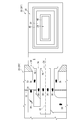
- FIG. 13 and 14 are views for explaining the configuration of the guide member 82 applicable to the burner 20, and FIG. 13 is a schematic front view of the burner 20 to which the guide member 82 is applied. 14 is a schematic cross-sectional view taken along line XIV-XIV in FIG.
- the guide member 82 is configured to guide at least a part of the mixed fluid 36 so as to flow along the furnace 5 side surface of the intermediate flame stabilizer 50.
- the intermediate flame holder 50 can be cooled and the intermediate flame holder 50 can be cooled by flowing a part of the mixed fluid 36 along the surface of the intermediate flame holder 50 on the furnace 5 side. It is possible to suppress ash adhesion on the surface.
- the guide member 82 is formed by a plate extending across the fuel supply nozzle 26 so as to cover a part of the surface of the intermediate flame stabilizer 50 on the furnace 5 side.
- the intermediate flame stabilizer 50 has a slit 84 at a position covered by the guide member 82, and a part of the mixed fluid 36 can pass through the slit 84.
- the mixed fluid 36 that has passed through the slit 84 bends by colliding with the guide member 82, flows along the surface of the intermediate flame holder 50 on the furnace 5 side, can cool the intermediate flame holder 50, and is intermediate. The ash adhesion to the flame holder 50 can be suppressed. Further, as shown in FIGS.
- the inner gas nozzle 24 has two or more inner gas flow paths 24 a and 24 b that respectively surround the axis 32 when viewed in the direction along the axis 32.
- the burners 20d and 20e have a flow rate of the inner combustion oxygen-containing gas 34 flowing through the innermost gas flow path 24a closest to the axis 32 when viewed in the direction along the axis 32 of the two or more inner gas flow paths 24a and 24b.
- the two or more inner gas flow paths 24 a and 24 b can be formed by disposing one or more cylindrical members inside the inner gas nozzle 24.
- the flow controller 88 can be configured by a door that can open and close the opening of the wall that forms the innermost gas flow path 24a.
- the reduced state is maintained in the internal flame holding region 40a regardless of the properties of the solid powder fuel by adjusting the flow rate of the inner combustion oxygen-containing gas 34 flowing through the innermost gas flow path 24a. And the generation of NOx can be suppressed.
- the fuel ratio of coal is the ratio of fixed carbon and volatile matter contained in each coal, and the higher the fuel ratio, the less volatile matter.
- the flow rate of the oxygen-containing gas 34 for internal combustion is large, the reduction becomes weak and the amount of NOx generated increases.
- the jet flow velocity Fc of the inner combustion oxygen-containing gas 34 may be reduced, and it may be difficult to form the internal flame holding region 40a.
- the innermost gas flow path 24a is formed compared to the case where the fuel ratio of coal is low (in the case of a medium to low fuel ratio).
- the flow regulator 88 is controlled to reduce the flow rate of the flowing inner combustion oxygen-containing gas 34.
- the flow rate (total flow rate) of the inner combustion oxygen-containing gas 34 can be reduced while maintaining the ejection flow rate Fc of the inner combustion oxygen-containing gas 34, and as a result, the internal flame holding region 40a is maintained. NOx generation can be suppressed.
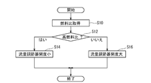
- FIG. 15 is a flowchart showing a schematic procedure of a control method applicable to the burners 20d and 20e provided with the flow rate regulator 88 described above.
- the control method of the burners 20d and 20e includes a step S10 for obtaining a fuel ratio, a step S12 for determining whether or not the fuel ratio is high, and a flow rate regulator when the fuel ratio is high.
- Step S14 for setting the opening of 88 small
- Step S16 for setting the opening of the flow rate controller 88 large when the fuel ratio is medium to low. Whether or not the fuel ratio is high can be determined by whether or not the fuel ratio exceeds a threshold value.
- a high coal fuel ratio means that the fuel ratio is about 2 or more
- a low coal fuel ratio means that the fuel ratio is less than about 2. It shall mean that.
- This threshold value also depends on the type of fuel and the particle size of the powdered fuel, and may be determined based on the test results in the combustion test furnace.
- the supply source of the inner combustion oxygen-containing gas 34 and the outer combustion oxygen-containing gas 38 is the same, if the flow rate of the inner combustion oxygen-containing gas 34 is reduced in the case of a high fuel ratio, As a result, the flow rate of the oxygen-containing gas 38 for outer combustion increases.
- the flow rate of the outer combustion oxygen-containing gas 38 is increased, the ejection flow rate Fo of the outer combustion oxygen-containing gas 38 is increased, and the ejection flow rate Fo of the outer combustion oxygen-containing gas 38 and the inner combustion oxygen-containing gas 34 are increased.
- the difference between the jet flow velocity Fc and the stability of ignition and flame holding in the internal flame holding region 40a is lowered.
- the intermediate flame holder 50 is used to form a flow of high-temperature gas from the external flame holding region 40b toward the internal flame holding region 40a using the pressure difference between the external flame holding region 40b and the internal flame holding region 40a. If this is the case, this fear becomes stronger.
- the flow area Fo of the outer gas nozzle 28 is sufficiently large so that the injection flow rate Fo of the outer combustion oxygen-containing gas 38 is optimized when the fuel ratio is high. Is given in advance.
- the flow rate (total flow rate) of the oxygen-containing gas 38 for outer combustion is decreased by the outer gas flow rate regulator 52, and the amount corresponding to the decreased amount is decreased for inner combustion.
- the flow rate (total flow rate) of the oxygen-containing gas 34 is increased.
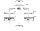
- FIG. 16 is a flowchart showing a schematic procedure of a control method applicable to the burners 20d and 20e provided with the flow rate regulator 88 described above.
- the control method shown in FIG. 16 includes a step of increasing the flow area of the outer gas nozzle 28 when the fuel ratio is high, that is, a step S18 of increasing the opening of the outer gas flow rate regulator 52, and a medium-low fuel.
- the method further includes a step of reducing the flow area of the outer gas nozzle 28, that is, a step S20 of reducing the opening of the outer gas flow rate regulator 52.
- the outer gas nozzle 28 has a first outer gas flow path 28a and a second outer gas flow path 28b as shown in FIG.
- the rate of decrease in the flow rate of the outer combustion oxygen-containing gas 38 in the second outer gas passage 28b is equal to the flow rate of the outer combustion oxygen-containing gas 38 in the first outer gas passage 28a.
- the outer gas flow controller 52 is operated so as to be larger than the decreasing rate.
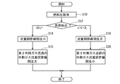
- FIG. 17 is a flowchart showing a schematic procedure of a control method applicable to the burner 20d provided with the flow rate regulator 88 described above.
- step S18 in which the opening degree of the outer gas flow rate regulator 52 is increased, the opening degree of the outer gas flow rate regulator 52 for the second outer gas flow path 28b is increased and the outer gas flow rate regulator 52 is increased.
- step S20 for reducing the opening degree of the flow rate regulator 52 the opening degree of the outer gas flow rate regulator 52 for the second outer gas flow path 28b is reduced.
- the flow rate (total flow rate) of the outer combustion oxygen-containing gas 38 is set when the fuel ratio is medium to low. If decreased, the jet flow velocity Fo of the outer combustion oxygen-containing gas 38 is lowered, and the outer circulation vortex 42b may be weakened. As a result, the stability of ignition and flame holding in the external flame holding region 40b may be reduced.
- the outer gas nozzle 28 includes a first outer gas channel 28a, a second outer gas channel 28b, and a third outer gas channel.
- the flow rate of the outer combustion oxygen-containing gas 38 in the second outer gas passage 28b is reduced.
- the outer gas flow rate regulator 52 is operated so that the decrease rate of the flow rate of the outer combustion oxygen-containing gas 38 in the third outer gas flow path 28c is larger than the decrease rate.
- the outer gas flow rate adjustment is performed so that the reduction rate of the flow rate of the outer combustion oxygen-containing gas 38 in the outermost outer gas passage is maximized.
- the device 52 is operated. Thereby, in the case of a medium-low fuel ratio, it is possible to suppress a decrease in the ejection flow rate Fo of the outer combustion oxygen-containing gas 38, and it is possible to suppress the outer circulation vortex 42b from becoming weak.
- FIG. 18 is a flowchart showing a schematic procedure of a control method applicable to the burner 20e including the flow rate adjuster 88 described above.
- step S18 in which the opening degree of the outer gas flow rate regulator 52 is increased, the opening degree of the outer gas flow rate regulator 52 for the third outer gas flow path 28c is increased, so that the outer gas flow rate is increased.
- step S20 for reducing the opening degree of the flow rate regulator 52 the opening degree of the outer gas flow rate regulator 52 for the third outer gas flow path 28c is reduced.
- control device 60 controls the flow rate ratio adjusting mechanism 30, the flow rate adjuster 88, and the outer gas flow rate adjuster 52 via a driving device (not shown) as shown in FIGS.
- the control method shown in FIGS. 15 to 18 can be automatically executed.
- the fuel ratio of the solid powder fuel can be input to the control device 60 automatically or manually.
- the flow rate ratio adjusting mechanism 30, the flow rate adjuster 88, and the outer gas flow rate adjuster 52 may be manually operated.
- the burners 20 c, 20 d, 20 e further comprise an oil nozzle 90 disposed along the axis 32.
- the oil nozzle 90 is used when the burners 20c, 20d, and 20e are activated.
- the solid powder fuel is pulverized coal
- the pulverized coal is obtained by pulverizing the coal by the mill 92 provided in the boiler 1.
- the pulverized coal is carried by the carrier gas sent from the blower 94 and supplied to the fuel supply nozzle 26 of the burner 20.
- the oxygen-containing gas is sent from the blower 96 to the wind box 22.
- the carrier gas and the oxygen-containing gas are, for example, air.
- a part of the carrier gas and the oxygen-containing gas can be heated to an appropriate temperature by the heater 98.
- the heater 98 may be incorporated in the boiler 1.
- an additional combustion gas nozzle 100 capable of supplying an oxygen-containing gas is attached to the furnace 5 above the burner 20.
- FIG. 21 schematically shows a configuration of a burner 20g which is a modification of the burner 20c.
- the plate-like member constituting the internal flame holder 46 is connected to the peripheral edge of the outlet portion of the inner gas nozzle 24 at an angle other than a right angle, for example, an obtuse angle exceeding 90 degrees.
- the plate-like member constituting the internal flame stabilizer 46 may be integrally connected to the plate-like member constituting the external flame stabilizer 48.
- the external flame stabilizer 48 may be disposed at the outlet of the outer gas nozzle 28 and configured so that the flow of the outer combustion oxygen-containing gas 38 deviates from the axis 32.
- the shape and arrangement are not limited to those illustrated in FIG.
- the plate-like member constituting the external flame holder 48 may be integrally connected to the plate-like member constituting the internal flame holder 46, or at the periphery of the outlet portion of the outer gas nozzle 28.
- the external flame stabilizer 48 may be configured by a plate-like member having an L-shaped cross section.
Abstract
Description
この種のバーナとして、特許文献1が開示する燃焼用バーナでは、燃料供給ノズルの先端外周部近傍の高温ガスを混合流体内に流入させる手段として、内部保炎用空気ノズルが設けられている。内部保炎用空気ノズルの噴出口からは、混合気ノズルの中心部に向けて空気噴流が噴出する。空気噴流には同伴作用があり、再循環高温ガスの一部が空気噴流に沿って混合気体の流れの中に流入し、その内部の着火保炎性能が高まる。また、空気噴流により混合気体の流れの乱れが増加するため、着火後の燃焼効率向上にも効果がある。
上記事情に鑑みて、本発明の少なくとも一実施形態の目的は、簡単な構成にて、内部保炎域における着火及び保炎の安定化を図れるバーナ、燃焼装置、ボイラ及びバーナの制御方法を提供することにある。
軸線を囲みながら該軸線に沿って延在し、内側燃焼用酸素含有ガスを火炉に供給可能な内側ガスノズルと、
前記軸線に沿う方向でみたときに前記内側ガスノズルを囲み、固体粉末燃料と搬送用ガスの混合流体を前記火炉に供給可能な燃料供給ノズルと、
前記軸線に沿う方向でみたときに前記燃料供給ノズルを囲み、外側燃焼用酸素含有ガスを前記火炉に供給可能な外側ガスノズルと、
前記内側燃焼用酸素含有ガスの噴出流速と前記外側燃焼用酸素含有ガスの噴出流速の相対的な流速比を調節可能な流速比調節機構と、を備え、
前記燃料供給ノズルの出口よりも下流にて、前記混合流体の噴出流の前記内側燃焼用酸素含有ガスの噴出流側と前記外側燃焼用酸素含有ガスの噴出流側に保炎域がそれぞれ形成されるように構成されている。
一方、燃料供給ノズルから噴出した混合流体の噴出流と外側燃焼用酸素含有ガスの噴出流との間には外側循環渦が形成される。外側循環渦を強くすれば、外側循環渦によって燃料供給ノズルに向かう外側高温ガス循環流の流量が増加し、外側高温ガス循環流の熱によって、外側燃焼用酸素含有ガスの噴出流側の外部保炎域における着火及び保炎の安定化を図れる。
ここで、外部保炎域は、内部保炎域よりも、周囲からの輻射等により着火や保炎が安定し易く、内部保炎域及び外部保炎域の各々における着火及び保炎の安定化に必要な内側燃焼用酸素含有ガスの噴出流速及び外側燃焼用酸素含有ガスの噴出流速は必ずしも相互に一致しない。この点、上記構成(1)によれば、流速比調節機構によって、内側燃焼用酸素含有ガスの噴出流速と外側燃焼用酸素含有ガスの噴出流速の相対的な流速比を調節することによって、内部保炎域及び外部保炎域の各々における着火及び保炎の安定化を図れる。
軸線を囲みながら該軸線に沿って延在し、内側燃焼用酸素含有ガスを火炉に供給可能な内側ガスノズルと、
前記軸線に沿う方向でみたときに前記内側ガスノズルを囲み、固体粉末燃料と搬送用ガスの混合流体を前記火炉に供給可能な燃料供給ノズルと、
前記軸線に沿う方向でみたときに前記燃料供給ノズルを囲み、外側燃焼用酸素含有ガスを前記火炉に供給可能な外側ガスノズルと、
前記内側ガスノズルの出口部に配置され、前記内側燃焼用酸素含有ガスの流れを絞るように構成された内部保炎器と、
前記外側ガスノズルの出口部に配置され、前記外側燃焼用酸素含有ガスの流れが前記軸線から逸れるように構成された外部保炎器と、
前記内側燃焼用酸素含有ガスの噴出流速と前記外側燃焼用酸素含有ガスの噴出流速の相対的な流速比を調節可能な流速比調節機構と、を備える。
前記燃料供給ノズルの出口部を横切るように前記内側ガスノズルの出口部と前記外側ガスノズルの出口部との間をそれぞれ延びる複数の中間保炎器を更に備える。
上記構成(3)では、中間保炎器が燃料供給ノズルの出口部を横切るように延びており、外部保炎域から内部保炎域に向かって、中間保炎器に沿って高温ガスが流れることができる。これにより、内部保炎域の温度を上昇させることができ、内部保炎域の着火及び保炎の安定化をより一層図れる。
前記内側燃焼用酸素含有ガスの噴出流速が前記外側燃焼用酸素含有ガスの噴出流速より速くなるように構成されている。
上記構成(4)では、内側燃焼用酸素含有ガスの噴出流速が、外側燃焼用酸素含有ガスの噴出流速よりも速いことにより、内部保炎域の圧力を外部保炎域の圧力より低くすることができ、外部保炎域から内部保炎域に向かって流れる高温ガスが流れ易くなり、内部保炎域の着火及び保炎の安定化を確実に図れる。
前記外側ガスノズルは、前記軸線に沿う方向でみて前記燃料供給ノズルをそれぞれ囲む2つ以上の外側ガス流路を有し、
前記外側燃焼用酸素含有ガスは、前記2つ以上の外側ガス流路を通じて前記火炉に供給可能である。
上記構成(5)では、2つ以上の外側ガス流路を通じて外側燃焼用酸素含有ガスを供給することで、外側燃焼用酸素含有ガスの流速や方向に分布をもたせることができ、内部保炎域及び外部保炎域の各々の着火及び保炎の安定化をより一層図れる。
前記2つ以上の外側ガス流路の少なくとも1つに配置された外側ガス流量調節器を更に備える。
上記構成(6)では、外側ガス流量調節器によって、外側ガス流量調節器が配置された外側ガス流路から流出する外側燃焼用酸素含有ガスの流量を調節することができ、内部保炎域及び外部保炎域の各々の着火及び保炎の安定化をより一層図れる。
前記内側ガスノズルは、前記軸線に沿う方向でみて前記軸線をそれぞれ囲む2つ以上の内側ガス流路を有し、
前記2つ以上の内側ガス流路のうち前記軸線に沿う方向でみて最も内側に位置する最内燃焼用ガス供給流路を流れる前記内側燃焼用酸素含有ガスの流量を調節可能な流量調節器を更に備える。
前記流速比調節機構を自動的に制御可能な制御装置を更に備える。
上記構成(8)では、制御装置によって流速比調節機構を自動的に制御することで、内部保炎域及び外部保炎域の各々の着火及び保炎の安定化を容易且つ確実に図れる。
前記内側ガスノズルの出口部又は前記外側ガスノズルの出口部に設けられた圧力センサを更に備え、
前記制御装置は、前記圧力センサの出力に基づいて前記流速比調節機構を制御可能である。
上記構成(9)では、制御装置が圧力センサの出力基づいて流速比調節機構を制御することによって、内部保炎域及び外部保炎域の各々の着火及び保炎の安定化を容易且つ確実に図れる。
前記内側ガスノズルの出口部に配置されて前記内側燃焼用酸素含有ガスの流れを絞るように構成された内部保炎器、前記外側ガスノズルの出口部に配置されて前記外側燃焼用酸素含有ガスの流れが前記軸線から逸れるように構成された外部保炎器、及び、前記燃料供給ノズルの出口部を横切るように前記内側ガスノズルの出口部と前記外側ガスノズルの出口部との間をそれぞれ延びる複数の中間保炎器のうち少なくとも1つの保炎器と、
前記内側燃焼用酸素含有ガス、前記外側燃焼用酸素含有ガス又は前記混合流体のうち少なくとも一部を、前記少なくとも1つの保炎器の前記火炉側表面に沿って流れるように案内可能な案内部材と、を備える。
風箱と、
前記風箱によって覆われた上記構成(1)乃至(10)の何れか1項に記載のバーナと
を備える。
上記構成(11)の燃焼装置は、上記構成(1)乃至(10)の何れか1つのバーナを採用することによって、内部保炎域及び外部保炎域の各々の着火及び保炎の安定化を図れる。
火炉と、
前記火炉に取り付けられた風箱と、
前記火炉に取り付けられ且つ前記風箱によって覆われた上記構成(1)乃至(10)の何れか1項に記載のバーナと
を備える。
上記構成(12)のボイラは、上記構成(1)乃至(10)の何れか1つのバーナを採用することによって、内部保炎域及び外部保炎域の各々の着火及び保炎の安定化を図れる。
軸線を囲みながら該軸線に沿って延在し、内側燃焼用酸素含有ガスを火炉に供給可能な内側ガスノズルと、
前記軸線に沿う方向でみたときに前記内側ガスノズルを囲み、固体粉末燃料と搬送用ガスの混合流体を前記火炉に供給可能な燃料供給ノズルと、
前記軸線に沿う方向でみたときに前記燃料供給ノズルを囲み、外側燃焼用酸素含有ガスを前記火炉に供給可能な外側ガスノズルと、
前記内側燃焼用酸素含有ガスの噴出流速と前記外側燃焼用酸素含有ガスの噴出流速の相対的な流速比を調節可能な流速比調節機構と、を備え、
前記燃料供給ノズルの出口よりも下流にて、前記混合流体の前記内側燃焼用酸素含有ガスの噴出流側と前記外側燃焼用酸素含有ガスの噴出流側に保炎域がそれぞれ形成されるように構成され、
前記内側ガスノズルは、前記軸線に沿う方向でみて前記軸線をそれぞれ囲む2つ以上の内側ガス流路を有し、
前記2つ以上の内側ガス流路のうち前記軸線に沿う方向でみて最も内側に位置する最内燃焼用ガス供給流路を流れる前記内側燃焼用酸素含有ガスの流量を調節可能な流量調節器を更に備える、バーナの制御方法において、
前記固体粉末燃料の燃料比が閾値を超えている場合に、前記固体粉末燃料の燃料比が閾値以下である場合よりも、前記流量調節器の開度を小さく設定する。
前記外側燃焼用酸素含有ガスの流量を調節可能な外側ガス流量調節器を更に備え、
前記固体粉末燃料の燃料比が閾値を超えている場合に、前記固体粉末燃料の燃料比が閾値以下である場合よりも、前記外側ガス流量調節器の開度を大きく設定する。
前記外側ガスノズルは、前記軸線に沿う方向でみて前記燃料供給ノズルをそれぞれ囲む2つ以上の外側ガス流路を有し、
前記外側燃焼用酸素含有ガスは、前記2つ以上の外側ガス流路を通じて前記火炉に供給可能であり、
前記外側ガス流量調節器は、最も外側の外側ガス流路における前記外側燃焼用酸素含有ガスの流量を調節可能であり、
前記固体粉末燃料の燃料比が閾値を超えている場合に、前記固体粉末燃料の燃料比が閾値以下である場合よりも、前記外側ガス流量調節器の開度を大きく設定する。
例えば、「ある方向に」、「ある方向に沿って」、「平行」、「直交」、「中心」、「同心」或いは「同軸」等の相対的或いは絶対的な配置を表す表現は、厳密にそのような配置を表すのみならず、公差、若しくは、同じ機能が得られる程度の角度や距離をもって相対的に変位している状態も表すものとする。
例えば、「同一」、「等しい」及び「均質」等の物事が等しい状態であることを表す表現は、厳密に等しい状態を表すのみならず、公差、若しくは、同じ機能が得られる程度の差が存在している状態も表すものとする。
例えば、四角形状や円筒形状等の形状を表す表現は、幾何学的に厳密な意味での四角形状や円筒形状等の形状を表すのみならず、同じ効果が得られる範囲で、凹凸部や面取り部等を含む形状も表すものとする。
一方、一の構成要素を「備える」、「具える」、「具備する」、「含む」、又は、「有する」という表現は、他の構成要素の存在を除外する排他的な表現ではない。
ここで、固体粉末燃料とは、石炭、オイルコークス、固体状バイオマスなどの単体或いは混合物を粉砕した微粉状の燃料をいう。
内側ガスノズル24は、軸線32を囲みながら該軸線32に沿って延在し、内側燃焼用酸素含有ガス34を火炉5に供給可能である。軸線32は、火炉5の外壁に対し直交していても傾斜していてもよい。内側燃焼用酸素含有ガス34は例えば空気である。また、例えば、排ガスを再循環させて、これに酸素を混合させて燃焼用ガスとして用いる酸素燃焼を適用する場合には、燃焼用酸素含有ガスは二酸化炭素と酸素が主体の混合ガスとなる。
燃料供給ノズル26は、軸線32に沿う方向でみたときに内側ガスノズル24を囲み、固体粉末燃料と搬送用ガスの混合流体36を火炉5に供給可能である。固体粉末燃料は例えば微粉炭であり、搬送用ガスは例えば空気である。
流速比調節機構30は、内側燃焼用酸素含有ガス34の噴出流速Fcと外側燃焼用酸素含有ガス38の噴出流速Foの相対的な流速比を調節可能である。
そして、バーナ20は、燃料供給ノズル26の出口よりも下流にて、混合流体36の噴出流の内側燃焼用酸素含有ガス34側及び外側燃焼用酸素含有ガス38側に、内部保炎域40a及び外部保炎域40bがそれぞれ形成されるように構成されている。なお、内部保炎域40a及び外部保炎域40bとは、固体粉末燃料が着火して燃焼する領域である。内部保炎域40a及び外部保炎域40bは、燃料供給ノズル26の出口の直下流に形成される。
一方、燃料供給ノズル26から噴出した混合流体36と外側ガスノズル28から噴出した外側燃焼用酸素含有ガス38との間には外側循環渦42bが形成される。外側循環渦42bを強くすれば、外側循環渦42bによって、燃料供給ノズル26に向かう高温ガスの流れ(外側高温ガス循環流44b)の流量が増加し、外側高温ガス循環流44bの熱によって、外側燃焼用酸素含有ガス38側の外部保炎域40bにおける着火及び保炎の安定化を図れる。
なお、内側燃焼用酸素含有ガス34の噴出流速Fcと外側燃焼用酸素含有ガス38の噴出流速Foの相対的な流速比を調節可能であれば、国際公開第98/03819号に記載された内部保炎用空気ノズルを設けなくても、内部保炎域40a及び外部保炎域40bの各々の着火及び保炎の安定化を図れる。
なお、本明細書において、筒形状とは、図2、図4及び図5に示したような円筒形状に限定されず、図9に示したような多角形筒形状も含むものとする。
内部保炎器46は、内側ガスノズル24の出口部に配置され、内側燃焼用酸素含有ガス34の流れを絞るように構成されている。
外部保炎器48は、外側ガスノズル28の出口部に配置され、外側燃焼用酸素含有ガス38の流れが軸線32から逸れるように構成されている。
なお、バーナ20が内部保炎器46及び外部保炎器48を更に備えている場合には、バーナ20にとって、内部保炎域40a及び外部保炎域40bをそれぞれ形成するための他の構成は必須ではない。
幾つかの実施形態では、外部保炎器48は、外側ガスノズル28の出口部の周縁から外側に向かって延びる板形状の部材によって構成される。
なお本明細書においては、特に断らない限り、内側とは、軸線32に対し交差する方向(径方向)にて軸線32に近い側をさし、外側とは、軸線32から遠い側をさすものとする。
この構成によれば、内側燃焼用酸素含有ガス34の流路及び外側燃焼用酸素含有ガス38の流路の入口が同一のガス供給源である風箱22に接続されているので、内側燃焼用酸素含有ガス34の流路に配置されたダンパによって、簡単な構成にて確実に、内側燃焼用酸素含有ガス34の噴出流速Fcと外側燃焼用酸素含有ガス38の噴出流速Foの相対的な流速比を調節可能である。
幾つかの実施形態では、中間保炎器50は、燃料供給ノズル26の出口部を横切るように配置された板形状の部材によって構成される。
上記したバーナ20では、内側燃焼用酸素含有ガス34の噴出流速Fcが、外側燃焼用酸素含有ガス38の噴出流速Foよりも速いことにより、外部保炎域40bから内部保炎域40aに向かって流れる高温ガスの流量が増加し、内部保炎域40aの着火及び保炎の安定化を確実に図れる。
なお、例えば、2つ以上の外側ガス流路28a,28b,28cは、外側ガスノズル28の内部に1つ以上の筒形状の部材を配置することにより形成可能である。
上記したバーナ20c,20d,20eでは、外側ガス流量調節器52によって、外側ガス流路28a,28b,28cのうち外側ガス流量調節器52が配置された外側ガス流路から流出する外側燃焼用酸素含有ガス38の流量を調節することができる。これによって、内部保炎域40a及び外部保炎域40bの各々の着火及び保炎の安定化をより一層図れる。
なお例えば、外側ガス流量調節器52は、可動ベーンやダンパによって構成される。
上記したバーナ20c,20d,20eでは、第2外側ガス流路28bを流れる外側燃焼用酸素含有ガス38によって、外側循環渦42bが大きくなり、外部保炎域40bの着火及び保炎の安定化をより一層図れる。外側燃焼用酸素含有ガス38の流れが広がることで、内部保炎域40a及び外部保炎域40bに亘る還元域が大きくなり、NOx生成が抑制される。
幾つかの実施形態では、第2外側ガス案内板54は、円錐台形状の部材によって構成されている。
上記したバーナ20c,20d,20eによれば、第2外側ガス流路28bを流れる外側燃焼用酸素含有ガス38に旋回成分を付与することによって、外側循環渦42bが大きくなり、外部保炎域40bの着火及び保炎の安定化をより一層図れる。また、第2外側ガス流路28bを流れる外側燃焼用酸素含有ガス38に旋回成分を付与することによって、外側循環渦42bがさらに拡大され外部保炎域40bの着火及び保炎の安定化がさらに促進されるとともに、内部保炎域40a及び外部保炎域40bに亘る還元域がさらに大きくなり、NOx生成がさらに抑制される。
なお、旋回付与機構56は、固定されていても可動であってもよい。例えば旋回付与機構56は、固定ベーンや可動ベーンによって構成される。
幾つかの実施形態では、図8に示したように、バーナ20eは、第3外側ガス流路28cに配置された旋回付与機構56を更に備える。
上記したバーナ20では、制御装置60によって流速比調節機構30を自動的に制御することで、内部保炎域40a及び外部保炎域40bの各々の着火及び保炎の安定化を容易且つ確実に図れる。
上記したバーナ20では、制御装置60が圧力センサ62a,62bの出力基づいて流速比調節機構30を制御することによって、内部保炎域40a及び外部保炎域40bの各々の着火及び保炎の安定化を容易且つ確実に図れる。
幾つかの実施形態では、濃縮器66は、燃料供給ノズル26の内壁を囲むように配置された部材であって、燃料供給ノズル26の内壁と外壁との間に、これら内壁及び外壁の各々と隙間を存して配置された部材によって構成される。当該部材によれば、混合流体36を内壁側と外壁側とに分離することができ、搬送用ガスに比べて比重が大である固体粉末燃料を、内壁側と外壁側に偏らせることができる。
例えば、濃縮器66は、環形状の部材によって構成され、図示しない支持部材によって支持される。
上記した案内部材70によれば、内部保炎器46の火炉5側表面に沿って内側燃焼用酸素含有ガス34の一部を流すことで、内部保炎器46を冷却することができるとともに内部保炎器46への灰付着の抑制を可能とする。
なお、本明細書において、環形状という表現には、円形状の外に、多角形状等も含まれるものとする。
上記した案内部材76によれば、外部保炎器48の火炉5側表面に沿って外側燃焼用酸素含有ガス38の一部を流すことで、外部保炎器48を冷却することができるとともに外部保炎器48への灰付着の抑制を可能とする。
図14に示したように、案内部材82は、混合流体36のうち少なくとも一部を、中間保炎器50の火炉5側表面に沿って流れるように案内するように構成される。
上記した案内部材82によれば、中間保炎器50の火炉5側表面に沿って混合流体36の一部を流すことで、中間保炎器50を冷却することができるとともに中間保炎器50への灰付着の抑制を可能とする。
また、図13及び図14に示したように、案内部材82が中間保炎器50の中央部を覆っている場合、外側高温ガス循環流44bの両側に外側循環渦42cが形成され、外部保炎域40bにおける着火及び保炎をより一層安定させることができる。
例えば、2つ以上の内側ガス流路24a,24bは、内側ガスノズル24の内部に1つ以上の筒形状の部材を配置することにより形成可能である。また、流量調節器88は、最内ガス流路24aを形成する壁の開口を開閉可能な扉によって構成可能である。
ここで、固体粉末燃料の性状としては、例えば、石炭の燃料比をあげることができる。石炭の燃料比は、石炭にそれぞれ含まれる固定炭素と揮発分の比であり、燃料比が高いほど、揮発分が少ない。高燃料比の石炭を用いた場合、揮発分が少ないため、内側燃焼用酸素含有ガス34の流量が多いと、還元が弱くなり、NOx生成量が増加してしまう。しかしながら、内側燃焼用酸素含有ガス34の流量を単に減少させた場合、内側燃焼用酸素含有ガス34の噴出流速Fcが低下し、内部保炎域40aの形成が困難になるおそれがある。
燃料比が高いか否かは、燃料比が閾値を超えているか否かで判定することができる。例えば、石炭の燃料比が高い(高燃料比)とは、燃料比がおよそ2以上であることをさし、石炭の燃料比が低い(中低燃料比)とは、燃料比がおよそ2未満であることをさすものとする。この閾値は、燃料の種類や粉末燃料の粒度にも依存し、燃焼試験炉での試験結果などに基づき決定してよい。
このような点を考慮し、幾つかの実施形態では、高燃料比の場合に外側燃焼用酸素含有ガス38の噴出流速Foが最適になるよう、外側ガスノズル28の流路面積に十分な大きさが予め与えられる。そして、中低燃料比の場合には、外側ガス流量調節器52によって、外側燃焼用酸素含有ガス38の流量(総流量)が減少させられ、この減少分に対応する量にて、内側燃焼用酸素含有ガス34の流量(総流量)が増加させられる。
このような点を考慮し、幾つかの実施形態では、図8に示したように外側ガスノズル28が第1外側ガス流路28a、第2外側ガス流路28b、及び、第3外側ガス流路28cを有するバーナ20eにおいて、中低燃料比の場合に外側燃焼用酸素含有ガス38の流量(総流量)を減らす際に、第2外側ガス流路28bにおける外側燃焼用酸素含有ガス38の流量の減少率に比べ、第3外側ガス流路28cにおける外側燃焼用酸素含有ガス38の流量の減少率が大きくなるよう、外側ガス流量調節器52が操作される。換言すれば、外側ガスノズル28が複数の外側ガス流路を有する場合に、最外の外側ガス流路における外側燃焼用酸素含有ガス38の流量の減少率が最も大きくなるように、外側ガス流量調節器52が操作される。これにより、中低燃料比の場合に、外側燃焼用酸素含有ガス38の噴出流速Foの減少を抑制することができ、外側循環渦42bが弱くなることを抑制することができる。
なお、流速比調節機構30、流量調節器88及び外側ガス流量調節器52は、手動で操作するものであってもよい。
幾つかの実施形態では、火炉5に対し、バーナ20の上方に、酸素含有ガスを供給可能な追加燃焼用ガスノズル100が取り付けられる。
例えば、内部保炎器46は内側燃焼用酸素含有ガス34の流れを絞るように構成されていればよく、内部保炎器46の大きさ、形状及び配置等は図2等に例示したものに限定されることはない。ここで、図21は、バーナ20cの変形例であるバーナ20gの構成を概略的に示している。バーナ20gでは、内部保炎器46を構成する板状部材が、内側ガスノズル24の出口部の周縁に対し、直角以外の角度、例えば90度超の鈍角をもって連なっている。この外、内部保炎器46を構成する板状部材は、外部保炎器48を構成する板状部材に対し一体に連なっていてもよい。
一方、外部保炎器48は、外側ガスノズル28の出口部に配置され、外側燃焼用酸素含有ガス38の流れが軸線32から逸れるように構成されていればよく、外部保炎器48の大きさ、形状及び配置等は図2等に例示したものに限定されることはない。例えば、前述したように外部保炎器48を構成する板状部材は内部保炎器46を構成する板状部材に対し一体に連なっていてもよく、又、外側ガスノズル28の出口部の周縁に対し、直角以外の角度、例えば90度超の鈍角をもって連なっていてもよい。更に、外部保炎器48は、図21に示したように、断面L字形状の板状部材によって構成されていてもよい。
5 火炉
10 燃焼装置
20 バーナ
22 風箱
24 内側ガスノズル
24a,24b 内側ガス流路
26 燃料供給ノズル
28 外側ガスノズル
28a,28b,28c 外側ガス流路
30 流速比調節機構
32 軸線
34 内側燃焼用酸素含有ガス
36 混合流体
38 外側燃焼用酸素含有ガス
40a 内部保炎域
40b 外部保炎域
42a 内側循環渦
42b 外側循環渦
44a 内側高温ガス循環流
44b 外側高温ガス循環流
46 内部保炎器
48 外部保炎器
50 中間保炎器
52 外側ガス流量調節器
54 第2外側ガス案内板
56 旋回付与機構
60 制御装置
62a,62b 圧力センサ
64 駆動装置
66 濃縮器
70 案内部材
71 支持部材
72 隙間
73 隙間
76 案内部材
77 支持部材
78 隙間
79 隙間
82 案内部材
83 支持部材
84 隙間
85 隙間
88 流量調節器
90 油ノズル
92 ミル
94 送風機
96 送風機
98 加熱器
100 追加燃焼用ガスノズル
Claims (15)
- 軸線を囲みながら該軸線に沿って延在し、内側燃焼用酸素含有ガスを火炉に供給可能な内側ガスノズルと、
前記軸線に沿う方向でみたときに前記内側ガスノズルを囲み、固体粉末燃料と搬送用ガスの混合流体を前記火炉に供給可能な燃料供給ノズルと、
前記軸線に沿う方向でみたときに前記燃料供給ノズルを囲み、外側燃焼用酸素含有ガスを前記火炉に供給可能な外側ガスノズルと、
前記内側燃焼用酸素含有ガスの噴出流速と前記外側燃焼用酸素含有ガスの噴出流速の相対的な流速比を調節可能な流速比調節機構と、を備え、
前記燃料供給ノズルの出口よりも下流にて、前記混合流体の噴出流の前記内側燃焼用酸素含有ガスの噴出流側と前記外側燃焼用酸素含有ガスの噴出流側に保炎域がそれぞれ形成されるように構成されている
ことを特徴とするバーナ。 - 軸線を囲みながら該軸線に沿って延在し、内側燃焼用酸素含有ガスを火炉に供給可能な内側ガスノズルと、
前記軸線に沿う方向でみたときに前記内側ガスノズルを囲み、固体粉末燃料と搬送用ガスの混合流体を前記火炉に供給可能な燃料供給ノズルと、
前記軸線に沿う方向でみたときに前記燃料供給ノズルを囲み、外側燃焼用酸素含有ガスを前記火炉に供給可能な外側ガスノズルと、
前記内側ガスノズルの出口部に配置され、前記内側燃焼用酸素含有ガスの流れを絞るように構成された内部保炎器と、
前記外側ガスノズルの出口部に配置され、前記外側燃焼用酸素含有ガスの流れが前記軸線から逸れるように構成された外部保炎器と、
前記内側燃焼用酸素含有ガスの噴出流速と前記外側燃焼用酸素含有ガスの噴出流速の相対的な流速比を調節可能な流速比調節機構と、を備える
ことを特徴とするバーナ。 - 前記燃料供給ノズルの出口部を横切るように前記内側ガスノズルの出口部と前記外側ガスノズルの出口部との間をそれぞれ延びる複数の中間保炎器を更に備える
ことを特徴とする請求項1又は2に記載のバーナ。 - 前記内側燃焼用酸素含有ガスの噴出流速が前記外側燃焼用酸素含有ガスの噴出流速より速くなるように構成されている
ことを特徴とする請求項1乃至3の何れか1項に記載のバーナ。 - 前記外側ガスノズルは、前記軸線に沿う方向でみて前記燃料供給ノズルをそれぞれ囲む2つ以上の外側ガス流路を有し、
前記外側燃焼用酸素含有ガスは、前記2つ以上の外側ガス流路を通じて前記火炉に供給可能である
ことを特徴とする請求項1乃至4の何れか1項に記載のバーナ。 - 前記2つ以上の外側ガス流路の少なくとも1つに配置された外側ガス流量調節器を更に備える
ことを特徴とする請求項5に記載のバーナ。 - 前記内側ガスノズルは、前記軸線に沿う方向でみて前記軸線をそれぞれ囲む2つ以上の内側ガス流路を有し、
前記2つ以上の内側ガス流路のうち前記軸線に沿う方向でみて最も内側に位置する最内燃焼用ガス供給流路を流れる前記内側燃焼用酸素含有ガスの流量を調節可能な流量調節器を更に備える
ことを特徴とする請求項1乃至6の何れか1項に記載のバーナ。 - 前記流速比調節機構を自動的に制御可能な制御装置を更に備える
ことを特徴とする請求項1乃至7の何れか1項に記載のバーナ。 - 前記内側ガスノズルの出口部又は前記外側ガスノズルの出口部に設けられた圧力センサを更に備え、
前記制御装置は、前記圧力センサの出力に基づいて前記流速比調節機構を制御可能である
ことを特徴とする請求項8に記載のバーナ。 - 前記内側ガスノズルの出口部に配置されて前記内側燃焼用酸素含有ガスの流れを絞るように構成された内部保炎器、前記外側ガスノズルの出口部に配置されて前記外側燃焼用酸素含有ガスの流れが前記軸線から逸れるように構成された外部保炎器、及び、前記燃料供給ノズルの出口部を横切るように前記内側ガスノズルの出口部と前記外側ガスノズルの出口部との間をそれぞれ延びる複数の中間保炎器のうち少なくとも1つの保炎器と、
前記内側燃焼用酸素含有ガス、前記外側燃焼用酸素含有ガス又は前記混合流体のうち少なくとも一部を、前記少なくとも1つの保炎器の前記火炉側表面に沿って流れるように案内可能な案内部材と、を備える
ことを特徴とする請求項1乃至9の何れか1項に記載のバーナ。 - 風箱と、
前記風箱によって覆われた請求項1乃至10の何れか1項に記載のバーナと
を備えることを特徴とする燃焼装置。 - 火炉と、
前記火炉に取り付けられた風箱と、
前記火炉に取り付けられ且つ前記風箱によって覆われた請求項1乃至10の何れか1項に記載のバーナと
を備えることを特徴とするボイラ。 - 軸線を囲みながら該軸線に沿って延在し、内側燃焼用酸素含有ガスを火炉に供給可能な内側ガスノズルと、
前記軸線に沿う方向でみたときに前記内側ガスノズルを囲み、固体粉末燃料と搬送用ガスの混合流体を前記火炉に供給可能な燃料供給ノズルと、
前記軸線に沿う方向でみたときに前記燃料供給ノズルを囲み、外側燃焼用酸素含有ガスを前記火炉に供給可能な外側ガスノズルと、
前記内側燃焼用酸素含有ガスの噴出流速と前記外側燃焼用酸素含有ガスの噴出流速の相対的な流速比を調節可能な流速比調節機構と、を備え、
前記燃料供給ノズルの出口よりも下流にて、前記混合流体の噴出流の前記内側燃焼用酸素含有ガスの噴出流側と前記外側燃焼用酸素含有ガスの噴出流側に保炎域がそれぞれ形成されるように構成され、
前記内側ガスノズルは、前記軸線に沿う方向でみて前記軸線をそれぞれ囲む2つ以上の内側ガス流路を有し、
前記2つ以上の内側ガス流路のうち前記軸線に沿う方向でみて最も内側に位置する最内燃焼用ガス供給流路を流れる前記内側燃焼用酸素含有ガスの流量を調節可能な流量調節器を更に備える、バーナの制御方法において、
前記固体粉末燃料の燃料比が閾値を超えている場合に、前記固体粉末燃料の燃料比が閾値以下である場合よりも、前記流量調節器の開度を小さく設定する
ことを特徴とするバーナの制御方法。 - 前記外側燃焼用酸素含有ガスの流量を調節可能な外側ガス流量調節器を更に備え、
前記固体粉末燃料の燃料比が閾値を超えている場合に、前記固体粉末燃料の燃料比が閾値以下である場合よりも、前記外側ガス流量調節器の開度を大きく設定する
ことを特徴とする請求項13に記載のバーナの制御方法。 - 前記外側ガスノズルは、前記軸線に沿う方向でみて前記燃料供給ノズルをそれぞれ囲む2つ以上の外側ガス流路を有し、
前記外側燃焼用酸素含有ガスは、前記2つ以上の外側ガス流路を通じて前記火炉に供給可能であり、
前記外側ガス流量調節器は、最も外側の外側ガス流路における前記外側燃焼用酸素含有ガスの流量を調節可能であり、
前記固体粉末燃料の燃料比が閾値を超えている場合に、前記固体粉末燃料の燃料比が閾値以下である場合よりも、前記外側ガス流量調節器の開度を大きく設定する
ことを特徴とする請求項14に記載のバーナの制御方法。
Priority Applications (7)
| Application Number | Priority Date | Filing Date | Title |
|---|---|---|---|
| MYPI2017704001A MY190142A (en) | 2015-06-12 | 2016-05-30 | Burner, combustion device, boiler, and burner control method |
| US15/569,147 US10591156B2 (en) | 2015-06-12 | 2016-05-30 | Burner, combustion device, boiler, and burner control method |
| AU2016274736A AU2016274736B2 (en) | 2015-06-12 | 2016-05-30 | Burner, combustion device, boiler, and burner control method |
| CN201680024810.8A CN107532795A (zh) | 2015-06-12 | 2016-05-30 | 燃烧器、燃烧装置、锅炉及燃烧器的控制方法 |
| EP16807320.3A EP3276260B1 (en) | 2015-06-12 | 2016-05-30 | Burner, combustion device, boiler, and burner control method |
| KR1020177032223A KR102080380B1 (ko) | 2015-06-12 | 2016-05-30 | 버너, 연소 장치, 보일러 및 버너의 제어 방법 |
| CA2983989A CA2983989C (en) | 2015-06-12 | 2016-05-30 | Burner, combustion device, boiler, and burner control method |
Applications Claiming Priority (2)
| Application Number | Priority Date | Filing Date | Title |
|---|---|---|---|
| JP2015-119311 | 2015-06-12 | ||
| JP2015119311A JP6632226B2 (ja) | 2015-06-12 | 2015-06-12 | バーナ、燃焼装置、ボイラ及びバーナの制御方法 |
Publications (1)
| Publication Number | Publication Date |
|---|---|
| WO2016199613A1 true WO2016199613A1 (ja) | 2016-12-15 |
Family
ID=57503910
Family Applications (1)
| Application Number | Title | Priority Date | Filing Date |
|---|---|---|---|
| PCT/JP2016/065929 WO2016199613A1 (ja) | 2015-06-12 | 2016-05-30 | バーナ、燃焼装置、ボイラ及びバーナの制御方法 |
Country Status (10)
| Country | Link |
|---|---|
| US (1) | US10591156B2 (ja) |
| EP (1) | EP3276260B1 (ja) |
| JP (1) | JP6632226B2 (ja) |
| KR (1) | KR102080380B1 (ja) |
| CN (1) | CN107532795A (ja) |
| AU (1) | AU2016274736B2 (ja) |
| CA (1) | CA2983989C (ja) |
| MY (1) | MY190142A (ja) |
| TW (1) | TWI623705B (ja) |
| WO (1) | WO2016199613A1 (ja) |
Families Citing this family (6)
| Publication number | Priority date | Publication date | Assignee | Title |
|---|---|---|---|---|
| US11953201B2 (en) | 2013-02-14 | 2024-04-09 | Clearsign Technologies Corporation | Control system and method for a burner with a distal flame holder |
| JP6250847B1 (ja) | 2017-01-12 | 2017-12-20 | アトムメディカル株式会社 | チューブホルダ |
| EP3669121A1 (en) * | 2017-07-18 | 2020-06-24 | ClearSign Technologies Corporation | Control system for a burner with perforated flame holder |
| JP2020030037A (ja) * | 2018-08-20 | 2020-02-27 | 三菱日立パワーシステムズ株式会社 | 固体燃料バーナ |
| US11112111B2 (en) * | 2018-09-26 | 2021-09-07 | Taiheiyo Cement Corporation | Cement kiln burner device and method for operating the same |
| US20220003407A1 (en) * | 2020-07-01 | 2022-01-06 | Messer Industries Usa, Inc. | Burner, furnace and method of generating a flame |
Citations (10)
| Publication number | Priority date | Publication date | Assignee | Title |
|---|---|---|---|---|
| JPS588908A (ja) * | 1981-07-10 | 1983-01-19 | Sumitomo Cement Co Ltd | 微粉炭の燃焼方法およびその装置 |
| JPS59210205A (ja) * | 1983-05-14 | 1984-11-28 | Babcock Hitachi Kk | 微粉炭バ−ナ装置 |
| JPS6071810U (ja) * | 1983-10-19 | 1985-05-21 | 三菱重工業株式会社 | 微粉燃料用バ−ナ |
| JPH11148610A (ja) * | 1997-11-20 | 1999-06-02 | Babcock Hitachi Kk | 固体燃料燃焼用バーナと固体燃料用燃焼装置 |
| JP2002048306A (ja) * | 2000-08-04 | 2002-02-15 | Babcock Hitachi Kk | 燃焼用バーナおよび該バーナを備えた燃焼装置 |
| JP2002228109A (ja) * | 2001-01-29 | 2002-08-14 | Babcock Hitachi Kk | 固体燃料燃焼用バーナ及び該バーナを用いる燃焼方法及び燃焼装置 |
| WO2009130857A1 (ja) * | 2008-04-24 | 2009-10-29 | バブコック日立株式会社 | 微粉炭バーナ |
| JP2010038519A (ja) * | 2008-08-08 | 2010-02-18 | Ihi Corp | バーナ |
| JP2011252625A (ja) * | 2010-05-31 | 2011-12-15 | Ihi Corp | 微粉炭バーナ |
| JP2013019666A (ja) * | 2007-05-14 | 2013-01-31 | Babcock Hitachi Kk | 微粉炭ボイラの排ガス浄化システム |
Family Cites Families (26)
| Publication number | Priority date | Publication date | Assignee | Title |
|---|---|---|---|---|
| JPS5535885A (en) * | 1978-09-06 | 1980-03-13 | Kobe Steel Ltd | Combustion method capable of minimizing production of nitrogen oxide and smoke |
| JPS60235910A (ja) * | 1984-05-09 | 1985-11-22 | Nippon Furnace Kogyo Kaisha Ltd | 低負荷燃焼対策のバ−ナ |
| DE4325643A1 (de) * | 1993-07-30 | 1995-02-02 | Lentjes Kraftwerkstechnik | Brenner zum Verbrennen von staubförmigem Brennstoff |
| KR970009084B1 (ko) * | 1994-12-29 | 1997-06-05 | 김만제 | 탄소성분을 포함한 미분체 용융장치 및 이를 이용한 미분체 용융방법 |
| JPH09250709A (ja) * | 1996-03-14 | 1997-09-22 | Babcock Hitachi Kk | 固体燃料用バーナと燃焼装置 |
| JPH09280212A (ja) * | 1996-04-18 | 1997-10-28 | Ckd Corp | 緩衝機構付き流体圧シリンダ |
| US5850776A (en) | 1996-04-18 | 1998-12-22 | Ckd Corporation | Fluid pressure cylinders provided with impact absorbing mechanisms |
| EP1335164B1 (en) | 1996-07-19 | 2006-05-24 | Babcock-Hitachi Kabushiki Kaisha | Combustion burner |
| JP3009370B2 (ja) * | 1997-03-07 | 2000-02-14 | 株式会社日立製作所 | 微粉炭バーナ、微粉炭ボイラ及び微粉炭燃焼方法 |
| CN100453901C (zh) | 2000-08-04 | 2009-01-21 | 巴布考克日立株式会社 | 固体燃料燃烧器及使用固定燃料燃烧器的燃烧方法 |
| JP2002115810A (ja) * | 2000-10-12 | 2002-04-19 | Babcock Hitachi Kk | 低NOx固体燃料燃焼装置 |
| JP4508474B2 (ja) | 2001-06-07 | 2010-07-21 | 三菱重工業株式会社 | 燃焼器 |
| JP4261401B2 (ja) | 2004-03-24 | 2009-04-30 | 株式会社日立製作所 | バーナと燃料燃焼方法及びボイラの改造方法 |
| CN2763701Y (zh) * | 2005-02-25 | 2006-03-08 | 贾臻 | 预热型煤粉燃烧器 |
| CN100513879C (zh) * | 2005-10-12 | 2009-07-15 | 中铁宝桥股份有限公司 | 天然气超贫氧数控加热方法 |
| JP2007298190A (ja) * | 2006-04-27 | 2007-11-15 | Noritz Corp | 燃焼装置 |
| US7775791B2 (en) * | 2008-02-25 | 2010-08-17 | General Electric Company | Method and apparatus for staged combustion of air and fuel |
| AU2009233850B2 (en) | 2008-04-07 | 2014-04-10 | Edward Bacorn | Powdered fuel conversion systems and methods |
| EP2273193B1 (en) | 2008-04-10 | 2016-03-16 | Mitsubishi Hitachi Power Systems, Ltd. | Solid fuel burner, combustion apparatus using solid fuel burner |
| US20090280442A1 (en) * | 2008-05-05 | 2009-11-12 | American Air Liquide Inc. | Device And Method Of Combusting Solid Fuel With Oxygen |
| CN101988698A (zh) * | 2009-07-31 | 2011-03-23 | 戴卫军 | 一种旋流煤粉燃烧器 |
| EP2667094A1 (en) * | 2011-01-21 | 2013-11-27 | Babcock-Hitachi Kabushiki Kaisha | Solid fuel burner and combustion device using same |
| JP5809012B2 (ja) | 2011-10-14 | 2015-11-10 | 株式会社堀場エステック | 流量制御装置、流量測定機構、又は、当該流量測定機構を備えた流量制御装置に用いられる診断装置及び診断用プログラム |
| DE102012007884A1 (de) * | 2012-04-23 | 2013-10-24 | Babcock Borsig Steinmüller Gmbh | Brenner für staub- und/oder partikelförmige Brennstoffe mit veränderlichem Drall |
| JP6041662B2 (ja) * | 2012-12-20 | 2016-12-14 | 大阪瓦斯株式会社 | 粉体燃焼装置 |
| CN104566358B (zh) * | 2013-10-29 | 2017-02-08 | 烟台龙源电力技术股份有限公司 | 煤粉燃烧器以及锅炉 |
-
2015
- 2015-06-12 JP JP2015119311A patent/JP6632226B2/ja active Active
-
2016
- 2016-05-30 EP EP16807320.3A patent/EP3276260B1/en active Active
- 2016-05-30 MY MYPI2017704001A patent/MY190142A/en unknown
- 2016-05-30 AU AU2016274736A patent/AU2016274736B2/en active Active
- 2016-05-30 WO PCT/JP2016/065929 patent/WO2016199613A1/ja active Application Filing
- 2016-05-30 US US15/569,147 patent/US10591156B2/en active Active
- 2016-05-30 CN CN201680024810.8A patent/CN107532795A/zh active Pending
- 2016-05-30 CA CA2983989A patent/CA2983989C/en active Active
- 2016-05-30 KR KR1020177032223A patent/KR102080380B1/ko active IP Right Grant
- 2016-06-08 TW TW105118247A patent/TWI623705B/zh active
Patent Citations (10)
| Publication number | Priority date | Publication date | Assignee | Title |
|---|---|---|---|---|
| JPS588908A (ja) * | 1981-07-10 | 1983-01-19 | Sumitomo Cement Co Ltd | 微粉炭の燃焼方法およびその装置 |
| JPS59210205A (ja) * | 1983-05-14 | 1984-11-28 | Babcock Hitachi Kk | 微粉炭バ−ナ装置 |
| JPS6071810U (ja) * | 1983-10-19 | 1985-05-21 | 三菱重工業株式会社 | 微粉燃料用バ−ナ |
| JPH11148610A (ja) * | 1997-11-20 | 1999-06-02 | Babcock Hitachi Kk | 固体燃料燃焼用バーナと固体燃料用燃焼装置 |
| JP2002048306A (ja) * | 2000-08-04 | 2002-02-15 | Babcock Hitachi Kk | 燃焼用バーナおよび該バーナを備えた燃焼装置 |
| JP2002228109A (ja) * | 2001-01-29 | 2002-08-14 | Babcock Hitachi Kk | 固体燃料燃焼用バーナ及び該バーナを用いる燃焼方法及び燃焼装置 |
| JP2013019666A (ja) * | 2007-05-14 | 2013-01-31 | Babcock Hitachi Kk | 微粉炭ボイラの排ガス浄化システム |
| WO2009130857A1 (ja) * | 2008-04-24 | 2009-10-29 | バブコック日立株式会社 | 微粉炭バーナ |
| JP2010038519A (ja) * | 2008-08-08 | 2010-02-18 | Ihi Corp | バーナ |
| JP2011252625A (ja) * | 2010-05-31 | 2011-12-15 | Ihi Corp | 微粉炭バーナ |
Also Published As
| Publication number | Publication date |
|---|---|
| CA2983989A1 (en) | 2016-12-15 |
| JP2017003216A (ja) | 2017-01-05 |
| EP3276260B1 (en) | 2020-08-05 |
| CN107532795A (zh) | 2018-01-02 |
| TWI623705B (zh) | 2018-05-11 |
| AU2016274736B2 (en) | 2019-06-13 |
| KR102080380B1 (ko) | 2020-02-21 |
| MY190142A (en) | 2022-03-30 |
| EP3276260A4 (en) | 2018-06-20 |
| US20180142887A1 (en) | 2018-05-24 |
| EP3276260A1 (en) | 2018-01-31 |
| JP6632226B2 (ja) | 2020-01-22 |
| CA2983989C (en) | 2020-05-12 |
| KR20170134705A (ko) | 2017-12-06 |
| TW201712274A (zh) | 2017-04-01 |
| US10591156B2 (en) | 2020-03-17 |
| AU2016274736A1 (en) | 2017-11-09 |
Similar Documents
| Publication | Publication Date | Title |
|---|---|---|
| WO2016199613A1 (ja) | バーナ、燃焼装置、ボイラ及びバーナの制御方法 | |
| KR101660051B1 (ko) | 고체 연료 버너, 고체 연료 버너를 이용한 연소장치와 그 운전방법 | |
| KR100472900B1 (ko) | 미분탄용 연소기 | |
| KR20100061471A (ko) | 고체연료 버너, 고체연료 버너를 이용한 연소장치와 그 운전방법 | |
| JP5068183B2 (ja) | 燃焼方法およびシステム | |
| JP5832653B2 (ja) | 固体燃料バーナ | |
| JP5736583B2 (ja) | バーナ装置 | |
| JP2017003216A5 (ja) | ||
| JP5535521B2 (ja) | 石炭焚ボイラ | |
| JP2013029270A (ja) | 固体燃料バーナ | |
| KR101582729B1 (ko) | 연소 장치 | |
| WO2014027611A1 (ja) | 固体燃料バーナと該固体燃料バーナを備えた燃焼装置の運転方法 | |
| JP5797238B2 (ja) | 燃料バーナ及び旋回燃焼ボイラ | |
| JP2012255600A (ja) | 固体燃料バーナ及びそれを備えた燃焼装置 | |
| JP2010270990A (ja) | 燃料バーナ及び旋回燃焼ボイラ | |
| JP2007232328A (ja) | 二段燃焼用空気ポートとその運用方法及びボイラ | |
| JP2011052871A (ja) | 燃焼装置 |
Legal Events
| Date | Code | Title | Description |
|---|---|---|---|
| 121 | Ep: the epo has been informed by wipo that ep was designated in this application |
Ref document number: 16807320 Country of ref document: EP Kind code of ref document: A1 |
|
| ENP | Entry into the national phase |
Ref document number: 2983989 Country of ref document: CA |
|
| WWE | Wipo information: entry into national phase |
Ref document number: 15569147 Country of ref document: US |
|
| ENP | Entry into the national phase |
Ref document number: 20177032223 Country of ref document: KR Kind code of ref document: A |
|
| ENP | Entry into the national phase |
Ref document number: 2016274736 Country of ref document: AU Date of ref document: 20160530 Kind code of ref document: A |
|
| NENP | Non-entry into the national phase |
Ref country code: DE |