WO2016199282A1 - 部品実装ライン - Google Patents
部品実装ライン Download PDFInfo
- Publication number
- WO2016199282A1 WO2016199282A1 PCT/JP2015/066936 JP2015066936W WO2016199282A1 WO 2016199282 A1 WO2016199282 A1 WO 2016199282A1 JP 2015066936 W JP2015066936 W JP 2015066936W WO 2016199282 A1 WO2016199282 A1 WO 2016199282A1
- Authority
- WO
- WIPO (PCT)
- Prior art keywords
- circuit board
- ionizer
- component mounting
- static electricity
- mounting line
- Prior art date
- Legal status (The legal status is an assumption and is not a legal conclusion. Google has not performed a legal analysis and makes no representation as to the accuracy of the status listed.)
- Ceased
Links
Images




Classifications
-
- H—ELECTRICITY
- H05—ELECTRIC TECHNIQUES NOT OTHERWISE PROVIDED FOR
- H05K—PRINTED CIRCUITS; CASINGS OR CONSTRUCTIONAL DETAILS OF ELECTRIC APPARATUS; MANUFACTURE OF ASSEMBLAGES OF ELECTRICAL COMPONENTS
- H05K13/00—Apparatus or processes specially adapted for manufacturing or adjusting assemblages of electric components
Definitions
- the present invention relates to a component mounting line in which a plurality of process devices including a plurality of component mounters for mounting electronic components on a circuit board are arranged along a circuit board conveyance path.
- each component mounter continues to operate (turns on) the ionizer while the component mounting line is in operation (during production), so the operation time (on time) of each component mounter increases and power consumption increases. There is also a drawback that deterioration of the discharge part of the ionizer is likely to proceed.
- the problem to be solved by the present invention is to reduce the equipment cost for the static elimination measures of the circuit board of the component mounting line, reduce the power consumption during operation of the component mounting line, and extend the life of the ionizer. It is.
- each device such as a component mounting machine arranged in the current component mounting line is a circuit in order to suppress electrostatic charging due to friction with the circuit board carrying the inside. Since static electricity countermeasures such as grounding are taken at the part where the board comes into contact, the electrostatic charge to the circuit board being transferred in the component mounting line can be suppressed to some extent, but the circuit board carried into the component mounting line Is in a state of being charged with static electricity due to vibration during transportation up to that point.
- the present invention is carried into the uppermost component mounting machine among the plurality of component mounting machines in the component mounting line or upstream of the uppermost component mounting machine.
- An ionizer that neutralizes the circuit board with ionized air is disposed, and a neutralization control unit that controls on / off of the ionizer according to the electrostatic charge amount of the circuit board that is carried in is provided.
- the ionization controller controls on / off of the ionizer according to the electrostatic charge amount of the circuit board carried into the component mounting line, static electricity charged on the circuit board during the operation of the component mounting line can be removed. It is possible to control to turn on the ionizer for a necessary time and turn off the ionizer after the lapse of the time. As a result, the on-time of the ionizer can be made shorter than before, and the power consumption by the ionizer during operation of the component mounting line can be further reduced, and the lifetime of the ionizer can be extended.
- the static elimination control unit may be configured to neutralize the circuit board by turning on the ionizer for a time set according to the electrostatic charge amount of the circuit board measured in advance. If the electrostatic charge of a circuit board is measured with a static electricity measuring instrument before putting the circuit board into the component mounting line, the time required to neutralize the static electricity charged on the circuit board can be calculated easily. Can do.
- a static electricity measuring device that measures the amount of electrostatic charge remaining on the circuit board after charge removal by an ionizer, wherein the charge removal control unit is based on a measured value of the electrostatic charge amount of the circuit board measured by the static electricity measuring device.
- the on-time of the ionizer that neutralizes the next circuit board may be corrected. In this way, it is possible to eliminate static electricity while confirming the effect of neutralization by the ionizer during operation of the component mounting line, and to correct the on-time of the ionizer based on the measurement value of the electrostatic charge amount of the circuit board measured by the electrostatic meter.
- the on-time of the ionizer can be appropriately changed in accordance with the change in the electrostatic charge amount for each circuit board carried into the component mounting line.
- the circuit boards to be carried into the component mounting line are supplied in a state where a predetermined number of sheets are stacked, and are carried into the component mounting line one by one.
- Each circuit board to be carried in seems to be charged with static electricity to the same extent. Therefore, it can be estimated that if the electrostatic charge amount of the circuit board that has been previously carried in is increased or decreased, the electrostatic charge amount of the circuit board that is carried in next is increased or decreased in a similar manner.
- the static electricity measuring device for measuring the electrostatic charge amount of the circuit board before static elimination with an ionizer is provided, and the static elimination control unit is based on a measured value of the electrostatic charge amount of the circuit board measured by the static electricity measuring device.
- the on-time of the ionizer necessary for discharging static electricity charged on the circuit board may be determined. In this way, it is possible to accurately calculate the on-time of the ionizer necessary for discharging static electricity charged on the circuit board carried into the component mounting line based on the measured value of the electrostatic charge amount of the circuit board. .
- the static electricity measuring device for measuring the electrostatic charge amount of the circuit board being neutralized by the ionizer is provided, and the static elimination control unit is configured to measure the static electricity of the circuit board measured by the static electricity measuring device while the ionizer is on.
- the ionizer may be turned off when the measured value of the charge amount becomes less than the allowable value. In this way, even if the ionization performance of the ionizer changes due to deterioration over time or the like, static electricity charged on the circuit board can be reliably discharged to an allowable value or less.
- the static elimination control unit is configured to carry the circuit board into the area that can be eliminated by the ionizer by the board detection means.
- the ionizer may be turned on to start discharging the circuit board. If it does in this way, after confirming that the circuit board was carried in to the static elimination area by an ionizer, an ionizer can be turned on and static elimination can be started.
- FIG. 1 is a block diagram showing a configuration of a component mounting line according to the first embodiment of the present invention.
- FIG. 2 is a block diagram illustrating a configuration of a control system that controls on / off of the ionizer according to the first embodiment.
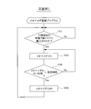
- FIG. 3 is a flowchart showing the flow of processing of the ionizer control program of the first embodiment.
- FIG. 4 is a block diagram illustrating a configuration of a component mounting line according to the second embodiment.
- FIG. 5 is a block diagram showing a configuration of a control system for controlling on / off of the ionizer of the third embodiment.
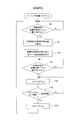
- FIG. 6 is a flowchart showing the flow of processing of the ionizer control program of the third embodiment.
- FIG. 7 is a flowchart showing the flow of processing of the ionizer control program of the fourth embodiment.
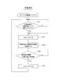
- FIG. 8 is a flowchart showing the flow of processing of the ionizer control program of the fifth embodiment.
- FIGS. 1 A first embodiment of the present invention will be described with reference to FIGS. First, the configuration of the component mounting line will be described with reference to FIG.
- each of the apparatus 11 to 14 in each process of the component mounting line is provided with a board conveyor for transporting the circuit board 10, and a simple grounding or the like is provided at a portion of the board conveyor where the circuit board 10 contacts.
- an ionizer 16 that neutralizes the circuit board 10 that is carried in by ionized air, and the circuit board 10 that is neutralized by the ionizer 16.
- a substrate sensor 17 substrate detection means is provided for detecting whether or not it has been carried into the possible area.
- the substrate sensor 17 may be a non-contact sensor such as an optical sensor or a proximity sensor, but may be a contact sensor such as a limit switch.
- the circuit board 10 may be imaged with a camera, and the carry-in of the circuit board 10 may be detected by image processing.
- the most upstream component mounter 11 provided with the ionizer 16 is provided with a static elimination control unit 21 for controlling on / off of the ionizer 16.
- the static elimination control unit 21 may also be configured to serve as a control device (not shown) of the most upstream component mounting machine 11 provided with the ionizer 16.
- the neutralization control unit 21 executes the ionizer control program shown in FIG. 3 to capture the output signal of the substrate sensor 17 and determine whether or not the circuit board 10 has been carried into an area where the ionizer 16 can be neutralized (step 101). ), When it is detected that the circuit board 10 has been carried into an area where the ionizer 16 can be removed, the ionizer 16 is turned on to start removing electricity from the circuit board 10 (step 102). Until the set time set according to the electrostatic charge amount elapses, the ionization of the circuit board 10 by the ionizer 16 is continued (step 103), and then the ionizer 16 is turned off when the set time elapses. 10 is terminated, and thereafter, the processing of steps 101 to 104 described above is repeated.
- the most upstream component mounting machine 11 mounts components on the circuit board 10 after the neutralization of the circuit board 10 is completed.
- the “set time” determined in step 103 is the amount of electrostatic charge (potential or potential) of the circuit board 10 by an operator using an electrostatic meter (not shown) before the circuit board 10 is put into the component mounting line. The amount of charge) is measured, the time required for the static electricity charged on the circuit board to be removed by the ionizer 16 is calculated, and the “set time” is set based on the calculated value.
- the circuit boards 10 to be carried into the component mounting line are supplied in a state where a predetermined number of sheets are stacked, and are carried into the component mounting line one by one.
- Each of the circuit boards 10 carried in is considered to be charged with static electricity to almost the same degree. Therefore, the operator does not need to measure the electrostatic charge amount of all the circuit boards 10 put into the component mounting line one by one, and may measure the electrostatic charge amount of the circuit board 10 at an appropriate interval.
- the circuit board 10 having a larger electrostatic charge amount is necessary in consideration of the variation range of the electrostatic charge amount of the circuit board 10 put into the component mounting line. What is necessary is just to set "setting time" so that static elimination time can be ensured.
- each of the devices 11 to 14 such as the component mounting machine 11 arranged in the component mounting line suppresses electrostatic charging due to friction or the like with respect to the circuit board 10 transporting the inside thereof.
- static electricity countermeasures such as grounding are taken at the part where the circuit board 10 contacts, static charge on the circuit board 10 being transferred in the component mounting line can be suppressed to some extent.
- the circuit board 10 to be loaded is in a state of being charged with static electricity due to vibration during transportation up to that point.
- an ionizer 16 is disposed inside the most upstream component mounting machine 11 among the plurality of component mounting machines 11 on the component mounting line, and measurement is performed before mounting the components.
- the circuit board 10 is discharged by turning on the ionizer 16 for a set time according to the electrostatic charge amount of the circuit board 10 thus formed.
- the circuit board 10 only needs to be neutralized by the ionizer 16 disposed inside the most upstream component mounting machine 11 among the plurality of component mounting machines 11 in the component mounting line, and the circuit board 10 is being transported in the component mounting line.
- the electrostatic charge on the circuit board 10 can be suppressed by a simple countermeasure against static electricity such as grounding, it is not necessary to provide the ionizer 16 for removing the circuit board 10 in each of the plurality of component mounting machines 11 on the component mounting line. As a result, it is possible to reduce the equipment cost for removing static electricity from the circuit board 10 of the component mounting line, and it is possible to reduce the power consumption by the ionizer 16 during operation of the component mounting line. Moreover, since the ionization controller 21 controls on / off of the ionizer 16 in accordance with the electrostatic charge amount of the circuit board 10 carried into the component mounting line, the static electricity charged on the circuit board 10 during the operation of the component mounting line.
- the ionizer 16 is turned on only for a time necessary for static elimination and the ionizer 16 is turned off after the time has elapsed.
- the on-time of the ionizer 16 can be made shorter than before, the power consumption by the ionizer 16 during operation of the component mounting line can be further reduced, and the life of the ionizer 16 can be extended.
- Embodiment 2 of the present invention will be described with reference to FIG.
- substantially the same parts as those in the first embodiment are denoted by the same reference numerals, description thereof is omitted or simplified, and different parts are mainly described.
- the ionizer 16 is disposed inside the most upstream component mounting machine 11 among the plurality of component mounting machines 11 in the component mounting line.
- a static elimination device 22 including an ionizer 16, a substrate sensor 17, and a static elimination control unit 21 is disposed upstream of the most upstream component mounting machine 11.
- the static eliminator 22 is arranged on the upstream side of the solder printer 12 that is the most upstream device on the component mounting line, but the static eliminator 22 is arranged on the downstream side of the solder printer 12. Also good.
- the static eliminator 22 may be disposed inside the solder printer 12. Also in the second embodiment described above, the same effect as in the first embodiment can be obtained.
- Embodiment 3 of the present invention will be described with reference to FIGS.
- substantially the same parts as those in the first and second embodiments are denoted by the same reference numerals, description thereof is omitted or simplified, and different parts are mainly described.
- a static electricity measuring device 23 for measuring the electrostatic charge amount (potential or charge amount) remaining on the circuit board 10 after being neutralized by the ionizer 16.
- the electrostatic measuring device 23 may be disposed at any position as long as it can measure the amount of electrostatic charge remaining on the circuit board 10 after being neutralized by the ionizer 16.
- the static electricity measuring device 23 may be disposed inside or downstream of the most upstream component mounting machine 11, and in the component mounting line of the second embodiment shown in FIG. 4, inside the static eliminating device 22 or downstream thereof.
- An electrostatic meter 23 may be disposed.
- the static elimination control unit 21 executes the ionizer control program shown in FIG.
- the ionizer control program in FIG. 6 is obtained by adding steps 105 and 106 to the ionizer control program in FIG. 3 described in the first embodiment.
- the neutralization control unit 21 executes the ionizer control program shown in FIG. 6 to turn on the ionizer 16 when the circuit board 10 is carried into the neutralization possible area by the ionizer 16, as in the first embodiment.
- the neutralization of the substrate 10 is started, and after the set time has elapsed, the ionizer 16 is turned off to terminate the neutralization of the circuit substrate 10 (steps 101 to 104). Thereafter, the electrostatic charge remaining on the circuit substrate 10 is measured by the electrostatic meter 23. Measure (Step 105).
- step 106 the set time in step 103 for determining the on-time of the ionizer 16 for discharging the next circuit board 10 is corrected based on the difference between the measured value of the electrostatic charge remaining on the circuit board 10 and the allowable value (step 106). ).
- the setting time is corrected in accordance with the difference between the two.
- the measured value of the electrostatic charge remaining on the circuit board 10 is less than the allowable value (when the measured value ⁇ the allowable value)
- the circuit board 10 is determined to be appropriate, and the set time is not corrected.
- the value of “allowable value ⁇ measured value” exceeds a predetermined value, it is determined that the charge removal time of the circuit board 10 is too long. Thus, correction is made in the direction of decreasing the set time according to the value of “allowable value ⁇ measured value”. Thereafter, the processing of steps 101 to 106 described above is repeated.
- the amount of electrical charge remaining on the circuit board 10 after being neutralized by the ionizer 16 is measured by the static electricity measuring device 23, and the next circuit board is based on the measured value of the electrostatic charge amount. Since the on-time (set time) of the ionizer 16 that neutralizes 10 is corrected, it is possible to eliminate static electricity while confirming the effect of ionization by the ionizer 16 during operation of the component mounting line, and based on the measured value of the electrostatic meter 23. By correcting the ON time of the ionizer 16, the ON time of the ionizer 16 can be appropriately changed in accordance with the change in the electrostatic charge amount for each circuit board 10 carried into the component mounting line.
- the circuit boards 10 to be carried into the component mounting line are supplied in a state where a predetermined number of sheets are stacked, and are carried into the component mounting line one by one.
- Each of the circuit boards 10 carried in is considered to be charged with static electricity to almost the same degree. Accordingly, it can be estimated that if the electrostatic charge amount of the circuit board 10 that has been previously carried in is increased or decreased, the electrostatic charge amount of the circuit board 10 that is carried in next is increased or decreased in a similar manner.
- Embodiment 4 of the present invention will be described with reference to FIG.
- substantially the same parts as those in the first to third embodiments are denoted by the same reference numerals, description thereof is omitted or simplified, and different parts are mainly described.
- the electrostatic charge remaining on the circuit board 10 after being neutralized by the ionizer 16 is measured by the static electricity measuring device 23.
- the circuit board before being neutralized by the ionizer 16 is measured.
- the electrostatic charge amount of 10 is measured by the static electricity measuring device 23.
- the static electricity measuring device 23 may be disposed at any position as long as the electrostatic charge amount of the circuit board 10 before the ionizer 16 is neutralized can be measured. For example, in the component mounting line of the first embodiment shown in FIG.
- the static electricity measuring device 23 may be disposed in the upstream component mounting machine 11 or upstream thereof, and in the component mounting line of the second embodiment shown in FIG. 4, static electricity measurement is performed in the static eliminating device 22 or upstream thereof.
- a container 23 may be arranged.
- the static elimination control unit 21 executes the ionizer control program of FIG. 7 to measure the electrostatic charge amount of the circuit board 10 before the static elimination by the ionizer 16 with the static electricity measuring device 23, and the circuit board.
- On-time (set time) of the ionizer 16 required to neutralize static electricity charged on the circuit board 10 is calculated based on the measured value of the electrostatic charge amount of 10. The processing contents of the ionizer control program shown in FIG. 7 will be described below.
- the ionizer control program in FIG. 7 is obtained by adding steps 98 to 100 to the ionizer control program in FIG. 3 described in the first embodiment.
- this program is started, first, in step 98, it is determined whether or not the circuit board 10 has been carried into the static electricity measurement area based on the output of a board sensor (not shown) or the like.
- the static electricity measurement area may be set on the upstream side of the area that can be neutralized by the ionizer 16, but the area that can be neutralized by the ionizer 16 is set at the same position as the static electricity measurement area.
- the ionizer 16 may be turned on to remove the static electricity from the circuit board 10.
- step 98 When it is determined in step 98 that the circuit board 10 has been carried into the static electricity measurement area, the process proceeds to step 99 and the electrostatic charge amount of the circuit board 10 is measured by the static electricity measuring device 23. Thereafter, the process proceeds to step 100, where a set time, which is a time required to neutralize the static electricity charged on the circuit board 10, is calculated based on the measured value of the electrostatic charge amount of the circuit board 10.
- a set time which is a time required to neutralize the static electricity charged on the circuit board 10
- the ionizer 16 is turned on to start removing electricity from the circuit board 10, and the setting calculated in the step 100 is performed. After the elapse of time, the ionizer 16 is turned off to complete the charge removal of the circuit board 10 (steps 101 to 104). Thereafter, the processing of steps 98 to 104 described above is repeated.
- the electrostatic charge amount of the circuit board 10 before being neutralized by the ionizer 16 is measured by the static electricity measuring device 23, and the circuit is based on the measured value of the electrostatic charge amount of the circuit board 10. Since the ON time (set time) of the ionizer 16 necessary for discharging static electricity charged on the board 10 is calculated, it is necessary to remove static electricity charged on the circuit board 10 carried into the component mounting line. The on-time (set time) of the ionizer 16 can be accurately calculated based on the measured value of the electrostatic charge amount of the circuit board 10. In addition, the same effects as those of the first embodiment can be obtained.
- Embodiment 5 of the present invention will be described with reference to FIG.
- substantially the same parts as those in the first to third embodiments are denoted by the same reference numerals, description thereof is omitted or simplified, and different parts are mainly described.
- the ON time (set time) of the ionizer 16 is set or corrected based on the measured value of the electrostatic charge amount of the circuit board 10 measured before or after the charge removal by the ionizer 16.
- the static elimination control unit 21 measures the electrostatic charge amount of the circuit board 10 being neutralized by the ionizer 16 by executing the ionizer control program of FIG. The ionizer 16 is turned off when the measured value of the electrostatic charge amount of the circuit board 10 becomes less than the allowable value.
- the ionizer control program of FIG. 8 is obtained by changing the process of step 103 of the ionizer control program of FIG. 3 described in the first embodiment to the processes of steps 103a and 103b.
- this program is started, when it is detected that the circuit board 10 has been carried into an area where the ionizer 16 can remove electricity, the ionizer 16 is turned on to start removing electricity from the circuit board 10 (steps 101 and 102). Thereafter, the process proceeds to step 103a, where the electrostatic charge amount of the circuit board 10 being neutralized by the ionizer 16 is measured by the static electricity measuring device 23, and in the next step 103b, the measured value of the electrostatic charge amount of the circuit board 10 is obtained. It is determined whether or not the allowable value has been reached.
- the static elimination of the circuit board 10 by the ionizer 16 is continued, and the electrostatic charge amount of the circuit board 10 is determined by the electrostatic meter. The process of measuring at 23 is repeated.
- step 103b when it is determined in step 103b that the measured value of the electrostatic charge amount of the circuit board 10 is equal to or less than the allowable value, the process proceeds to step 104, the ionizer 16 is turned off, and the charge removal of the circuit board 10 is completed. Thereafter, the processing of steps 101 to 104 described above is repeated.
- the electrostatic charge amount of the circuit board 10 being neutralized by the ionizer 16 is measured by the electrostatic meter 23, and the measured value of the electrostatic charge amount of the circuit board 10 is acceptable. Since the ionizer 16 is turned off when the value becomes lower than the value, even if the charge removal performance of the ionizer 16 changes due to deterioration with time or the like, the static electricity charged on the circuit board 10 can be reliably discharged below the allowable value. In addition, the same effects as those of the first embodiment can be obtained.
- the present invention is not limited to the above-described first to fifth embodiments.
- the configuration of the component mounting line may be changed as appropriate, and various modifications may be made without departing from the scope of the invention. Needless to say, you can.
Landscapes
- Engineering & Computer Science (AREA)
- Manufacturing & Machinery (AREA)
- Microelectronics & Electronic Packaging (AREA)
- Supply And Installment Of Electrical Components (AREA)
- Elimination Of Static Electricity (AREA)
Abstract
部品実装ラインの複数の部品実装機(11)のうちの最上流の部品実装機の内部又は前記最上流の部品実装機よりも上流側に、搬入される回路基板(10)を除電するイオナイザ(16)を配置すると共に、搬入される回路基板の静電気帯電量に応じて設定された時間だけイオナイザをオンして回路基板を除電する。回路基板の静電気帯電量は、部品実装ラインに投入する前に作業者が測定しても良いし、回路基板の静電気帯電量を測定する静電気測定器(23)を備えた構成としても良い。イオナイザで除電した後の回路基板の静電気帯電量を静電気測定器で測定して、その測定値に基づいて次の回路基板を除電するイオナイザのオン時間を補正したり、或は、イオナイザで除電する前の回路基板の静電気帯電量を静電気測定器で測定して、その測定値に基づいて、当該回路基板に帯電した静電気を除電するのに必要なイオナイザのオン時間を決定するようにしても良い。
Description
本発明は、回路基板に電子部品を実装する複数の部品実装機を含む複数の工程の装置を回路基板の搬送路に沿って配列した部品実装ラインに関する発明である。
部品実装ラインで回路基板に電子部品を実装する際に、回路基板に静電気が帯電していると、回路基板と電子部品との間で静電気が放電して電子部品の内部回路が破壊される可能性がある。この静電気対策として、特許文献1(特開2013-102246号公報)に記載されているように、部品実装機の基板コンベアの上方にイオナイザを配置し、基板コンベアで搬送する回路基板に対してイオナイザでイオン化したエアーを吹き付けて回路基板を除電するようにしたものがある。
一般に、1本の部品実装ラインには、複数の部品実装機が配列されているため、複数の部品実装機の各々にイオナイザを設けると、各部品実装機の構成が複雑化して各部品実装機の製造コストが高くなり、部品実装ラインの回路基板の除電対策のための設備コストが増加するという欠点がある。しかも、部品実装ラインの稼働中(生産中)に各部品実装機はそれぞれイオナイザを運転(オン)し続けるため、各部品実装機のイオナイザの運転時間(オン時間)が長くなり、消費電力の増加やイオナイザの放電部の劣化が進みやすいという欠点もある。
そこで、本発明が解決しようとする課題は、部品実装ラインの回路基板の除電対策のための設備コストを低減すると共に、部品実装ラインの稼働中の消費電力を低減し、イオナイザの寿命を延ばすことである。
本発明者らの実験や経験によれば、現在の部品実装ラインに配列された部品実装機等の各装置は、その内部を搬送する回路基板に対する摩擦等による静電気の帯電を抑えるために、回路基板が接触する部位にアース等の簡易な静電気対策が施されているため、部品実装ライン内における搬送中の回路基板への静電気の帯電はある程度抑えられるが、部品実装ラインに搬入する回路基板には、それまでの輸送時の振動等により静電気が帯電した状態になっている。
このような事情を考慮して、本発明は、部品実装ラインの複数の部品実装機のうちの最上流の部品実装機の内部又は前記最上流の部品実装機よりも上流側に、搬入される回路基板をイオン化したエアーにより除電するイオナイザを配置すると共に、搬入される回路基板の静電気帯電量に応じて前記イオナイザのオン/オフを制御する除電コントロール部を備えた構成としたものである。
この構成では、部品実装ラインの複数の部品実装機のうちの最上流の部品実装機の内部又は最上流の部品実装機よりも上流側に配置したイオナイザで回路基板を除電するだけで良く、部品実装ライン内における搬送中の回路基板への静電気の帯電はアース等の簡易な静電気対策によって抑えられるため、部品実装ラインの複数の部品実装機の各々に回路基板を除電するイオナイザを設ける必要がない。これにより、部品実装ラインの回路基板の除電対策のための設備コストの低減できると共に、部品実装ラインの稼働中のイオナイザによる消費電力も低減できる。しかも、部品実装ラインに搬入される回路基板の静電気帯電量に応じてイオナイザのオン/オフを除電コントロール部によって制御するため、部品実装ラインの稼働中に回路基板に帯電した静電気を除電するのに必要な時間だけイオナイザをオンさせて、その時間経過後にイオナイザをオフするという制御が可能となる。これにより、イオナイザのオン時間を従来より短くすることができて、部品実装ラインの稼働中のイオナイザによる消費電力を更に低減できると共に、イオナイザの寿命を延ばすことができる。
この場合、前記除電コントロール部は、予め測定された回路基板の静電気帯電量に応じて設定された時間だけ前記イオナイザをオンして回路基板を除電するようにしても良い。部品実装ラインに回路基板を投入する前に、静電気測定器で回路基板の静電気帯電量を測定すれば、その回路基板に帯電した静電気をイオナイザで除電するのに必要な時間を簡単に計算することができる。
更に、イオナイザで除電した後の回路基板に残留する静電気帯電量を測定する静電気測定器を備え、前記除電コントロール部は、前記静電気測定器で測定した前記回路基板の静電気帯電量の測定値に基づいて次の回路基板を除電するイオナイザのオン時間を補正するようにしても良い。このようにすれば、部品実装ラインの稼働中にイオナイザによる除電効果を確認しながら除電できると共に、静電気測定器で測定した回路基板の静電気帯電量の測定値に基づいてイオナイザのオン時間を補正することで、部品実装ラインに搬入する回路基板毎の静電気帯電量の変化に合わせてイオナイザのオン時間を適正に変化させることができる。部品実装ラインに搬入する回路基板は、所定枚数積み重ねた状態で供給され、1枚ずつ部品実装ラインに搬入されるため、1枚毎に静電気帯電量が大きく変化するものではなく、相前後して搬入される各回路基板は、ほぼ同じ程度に静電気が帯電しているものと思われる。従って、先に搬入した除電後の回路基板の静電気帯電量が増加又は減少すれば、次に搬入する回路基板の静電気帯電量もほぼ同様に増加又は減少するものと推定できる。
或は、イオナイザで除電する前の回路基板の静電気帯電量を測定する静電気測定器を備え、前記除電コントロール部は、前記静電気測定器で測定した前記回路基板の静電気帯電量の測定値に基づいて、当該回路基板に帯電した静電気を除電するのに必要な前記イオナイザのオン時間を決定するようにしても良い。このようにすれば、部品実装ラインに搬入する回路基板に帯電した静電気を除電するのに必要なイオナイザのオン時間を当該回路基板の静電気帯電量の測定値に基づいて正確に算出することができる。
或は、イオナイザで除電している最中の回路基板の静電気帯電量を測定する静電気測定器を備え、前記除電コントロール部は、前記イオナイザのオン中に前記静電気測定器で測定した回路基板の静電気帯電量の測定値が許容値以下になった時点でイオナイザをオフするようにしても良い。このようにすれば、イオナイザの除電性能が経時劣化等で変化しても、回路基板に帯電した静電気を確実に許容値以下に除電できる。
また、回路基板がイオナイザによる除電可能エリアに搬入されたか否かを検出するための基板検出手段を備え、前記除電コントロール部は、前記基板検出手段により回路基板が前記イオナイザによる除電可能エリアに搬入されたことが検出された時点で、前記イオナイザをオンして前記回路基板の除電を開始するようにすると良い。このようにすれば、回路基板がイオナイザによる除電可能エリアに搬入されたことを確認してからイオナイザをオンして除電を開始することができる。
以下、本発明を実施するための形態を具体化した5つの実施例1~5を説明する。
本発明の実施例1を図1乃至図3に基づいて説明する。
まず、図1に基づいて部品実装ラインの構成を説明する。
まず、図1に基づいて部品実装ラインの構成を説明する。
部品実装ラインには、回路基板10に部品を実装する複数の部品実装機11の他に、半田印刷機12、検査装置13、リフロー装置14等の各工程の装置が回路基板10の搬送ライン15に沿って配列されている。図示はしないが、部品実装ラインの各工程の装置11~14には、回路基板10を搬送する基板コンベアが設けられ、その基板コンベアのうちの回路基板10が接触する部位に、アース等の簡易な静電気対策が施されていて、搬送中の回路基板10への静電気の帯電がある程度抑えられるように構成されている。
部品実装ラインの複数の部品実装機11のうちの最上流の部品実装機11の内部には、搬入される回路基板10をイオン化したエアーにより除電するイオナイザ16と、回路基板10がイオナイザ16による除電可能エリアに搬入されたか否かを検出する基板センサ17(基板検出手段)が設けられている。基板センサ17は、光センサ、近接センサ等の非接触式センサを用いれば良いが、リミットスイッチ等の接触式センサを用いても良い。或は、カメラで回路基板10を撮像して、画像処理により回路基板10の搬入を検出するようにしても良い。
イオナイザ16が設けられた最上流の部品実装機11には、イオナイザ16のオン/オフを制御する除電コントロール部21が設けられている。尚、除電コントロール部21は、イオナイザ16が設けられた最上流の部品実装機11の制御装置(図示せず)が兼ねる構成としても良い。
除電コントロール部21は、図3のイオナイザ制御プログラムを実行することで、基板センサ17の出力信号を取り込んで、回路基板10がイオナイザ16による除電可能エリアに搬入されたか否かを判定し(ステップ101)、回路基板10がイオナイザ16による除電可能エリアに搬入されたことを検出した時点で、イオナイザ16をオンして回路基板10の除電を開始し(ステップ102)、予め測定された回路基板10の静電気帯電量に応じて設定された設定時間が経過するまで、イオナイザ16による回路基板10の除電を継続し(ステップ103)、その後、設定時間が経過した時点で、イオナイザ16をオフして回路基板10の除電を終了し、以後、上述したステップ101~104の処理を繰り返す。尚、最上流の部品実装機11は、回路基板10の除電が終了してから、当該回路基板10に部品を実装する。
この場合、上記ステップ103で判定する「設定時間」は、部品実装ラインに回路基板10を投入する前に、作業者が静電気測定器(図示せず)で回路基板10の静電気帯電量(電位又は電荷量)を測定して、その回路基板に帯電した静電気をイオナイザ16で除電するのに必要な時間を計算して、その計算値に基づいて「設定時間」を設定すれば良い。
部品実装ラインに搬入する回路基板10は、所定枚数積み重ねた状態で供給され、1枚ずつ部品実装ラインに搬入されるため、1枚毎に静電気帯電量が大きく変化するものではなく、相前後して搬入される各回路基板10は、ほぼ同じ程度に静電気が帯電しているものと思われる。従って、作業者は、部品実装ラインに投入する全ての回路基板10の静電気帯電量を1枚ずつ測定する必要はなく、適宜の間隔をあけて回路基板10の静電気帯電量を測定すれば良い。そして、回路基板10の静電気帯電量を測定する毎に、部品実装ラインに投入する回路基板10の静電気帯電量のばらつき範囲を考慮して、静電気帯電量が多い方の回路基板10でも、必要な除電時間を確保できるように「設定時間」を設定すれば良い。
本発明者らの実験や経験によれば、部品実装ラインに配列された部品実装機11等の各装置11~14は、その内部を搬送する回路基板10に対する摩擦等による静電気の帯電を抑えるために、回路基板10が接触する部位にアース等の簡易な静電気対策が施されているため、部品実装ライン内における搬送中の回路基板10への静電気の帯電はある程度抑えられるが、部品実装ラインに搬入する回路基板10には、それまでの輸送時の振動等により静電気が帯電した状態になっている。
このような事情を考慮して、本実施例では、部品実装ラインの複数の部品実装機11のうちの最上流の部品実装機11の内部にイオナイザ16を配置し、部品実装前に、予め測定された回路基板10の静電気帯電量に応じて設定された時間だけイオナイザ16をオンして回路基板10を除電するようにした。この構成では、部品実装ラインの複数の部品実装機11のうちの最上流の部品実装機11の内部に配置したイオナイザ16で回路基板10を除電するだけで良く、部品実装ライン内における搬送中の回路基板10への静電気の帯電はアース等の簡易な静電気対策によって抑えられるため、部品実装ラインの複数の部品実装機11の各々に回路基板10を除電するイオナイザ16を設ける必要がない。これにより、部品実装ラインの回路基板10の除電対策のための設備コストの低減できると共に、部品実装ラインの稼働中のイオナイザ16による消費電力も低減できる。しかも、部品実装ラインに搬入される回路基板10の静電気帯電量に応じてイオナイザ16のオン/オフを除電コントロール部21によって制御するため、部品実装ラインの稼働中に回路基板10に帯電した静電気を除電するのに必要な時間だけイオナイザ16をオンさせて、その時間経過後にイオナイザ16をオフするという制御が可能となる。これにより、イオナイザ16のオン時間を従来より短くすることができて、部品実装ラインの稼働中のイオナイザ16による消費電力を更に低減できると共に、イオナイザ16の寿命を延ばすことができる。
次に、図4を用いて本発明の実施例2を説明する。但し、前記実施例1と実質的に同じ部分については同一の符号を付して説明を省略又は簡略化し、主として異なる部分を説明する。
前記実施例1では、部品実装ラインの複数の部品実装機11のうちの最上流の部品実装機11の内部にイオナイザ16を配置したが、図4に示す実施例2では、部品実装ラインのうちの最上流の部品実装機11よりも上流側に、イオナイザ16、基板センサ17及び除電コントロール部21を備えた除電装置22を配置している。図4の構成例では、部品実装ラインの最上流の装置である半田印刷機12の上流側に除電装置22を配置しているが、半田印刷機12の下流側に除電装置22を配置しても良い。或は、半田印刷機12の内部に除電装置22を配置しても良い。
以上説明した本実施例2においても、前記実施例1と同様の効果を得ることができる。
以上説明した本実施例2においても、前記実施例1と同様の効果を得ることができる。
次に、図5及び図6を用いて本発明の実施例3を説明する。但し、前記実施例1,2と実質的に同じ部分については同一の符号を付して説明を省略又は簡略化し、主として異なる部分を説明する。
本実施例3では、イオナイザ16で除電した後の回路基板10に残留する静電気帯電量(電位又は電荷量)を測定する静電気測定器23(図5参照)を設けている。静電気測定器23を配置する位置は、イオナイザ16で除電した後の回路基板10に残留する静電気帯電量を測定できる位置であればどこでも良く、例えば、図1に示す実施例1の部品実装ラインでは、最上流の部品実装機11の内部又はその下流側に静電気測定器23を配置すれば良く、また、図4に示す実施例2の部品実装ラインでは、除電装置22の内部又はその下流側に静電気測定器23を配置すれば良い。
本実施例3では、除電コントロール部21は、図6のイオナイザ制御プログラムを実行する。図6のイオナイザ制御プログラムは、前記実施例1で説明した図3のイオナイザ制御プログラムに対してステップ105及び106の処理を追加したものである。
除電コントロール部21は、図6のイオナイザ制御プログラムを実行することで、前記実施例1と同様に、回路基板10がイオナイザ16による除電可能エリアに搬入された時点で、イオナイザ16をオンして回路基板10の除電を開始し、設定時間経過後にイオナイザ16をオフして回路基板10の除電を終了し(ステップ101~104)、その後、回路基板10に残留する静電気帯電量を静電気測定器23で測定する(ステップ105)。この後、回路基板10に残留する静電気帯電量の測定値と許容値との差に基づいて次の回路基板10を除電するイオナイザ16のオン時間を決めるステップ103の設定時間を補正する(ステップ106)。
例えば、回路基板10に残留する静電気帯電量の測定値が許容値を越えた場合(測定値>許容値の場合)は、両者の差に応じて設定時間を増加させる方向に補正する。一方、回路基板10に残留する静電気帯電量の測定値が許容値を下回る場合(測定値<許容値の場合)は、「許容値-測定値」の値が所定値以内であれば、回路基板10の除電時間が適切であると判断して、設定時間を補正しないが、「許容値-測定値」の値が所定値を越えていれば、回路基板10の除電時間が長すぎると判断して、「許容値-測定値」の値に応じて設定時間を減少させる方向に補正する。以後、上述したステップ101~106の処理を繰り返す。
以上説明した本実施例3によれば、イオナイザ16で除電した後の回路基板10に残留する電気帯電量を静電気測定器23で測定し、その静電気帯電量の測定値に基づいて次の回路基板10を除電するイオナイザ16のオン時間(設定時間)を補正するようにしたので、部品実装ラインの稼働中にイオナイザ16による除電効果を確認しながら除電できると共に、静電気測定器23の測定値に基づいてイオナイザ16のオン時間を補正することで、部品実装ラインに搬入する回路基板10毎の静電気帯電量の変化に合わせてイオナイザ16のオン時間を適正に変化させることができる。部品実装ラインに搬入する回路基板10は、所定枚数積み重ねた状態で供給され、1枚ずつ部品実装ラインに搬入されるため、1枚毎に静電気帯電量が大きく変化するものではなく、相前後して搬入される各回路基板10は、ほぼ同じ程度に静電気が帯電しているものと思われる。従って、先に搬入した除電後の回路基板10の静電気帯電量が増加又は減少すれば、次に搬入する回路基板10の静電気帯電量もほぼ同様に増加又は減少するものと推定できる。
次に、図7を用いて本発明の実施例4を説明する。但し、前記実施例1~3と実質的に同じ部分については同一の符号を付して説明を省略又は簡略化し、主として異なる部分を説明する。
前記実施例3では、イオナイザ16で除電する後の回路基板10に残留する静電気帯電量を静電気測定器23で測定するようにしたが、本実施例4では、イオナイザ16で除電する前の回路基板10の静電気帯電量を静電気測定器23で測定するようにしている。静電気測定器23を配置する位置は、イオナイザ16で除電する前の回路基板10の静電気帯電量を測定できる位置であればどこでも良く、例えば、図1に示す実施例1の部品実装ラインでは、最上流の部品実装機11の内部又はその上流側に静電気測定器23を配置すれば良く、また、図4に示す実施例2の部品実装ラインでは、除電装置22の内部又はその上流側に静電気測定器23を配置すれば良い。
本実施例4では、除電コントロール部21は、図7のイオナイザ制御プログラムを実行することで、イオナイザ16で除電する前の回路基板10の静電気帯電量を静電気測定器23で測定し、当該回路基板10の静電気帯電量の測定値に基づいて当該回路基板10に帯電した静電気を除電するのに必要なイオナイザ16のオン時間(設定時間)を算出する。以下、図7のイオナイザ制御プログラムの処理内容を説明する。
図7のイオナイザ制御プログラムは、前記実施例1で説明した図3のイオナイザ制御プログラムに対してステップ98~100の処理を追加したものである。本プログラムが起動されると、まず、ステップ98で、回路基板10が静電気測定エリアに搬入されたか否かを基板センサ(図示せず)等の出力に基づいて判定する。ここで、静電気測定エリアは、イオナイザ16による除電可能エリアよりも上流側に設定すれば良いが、イオナイザ16による除電可能エリアを静電気測定エリアと同じ位置として、イオナイザ16による除電可能エリアで回路基板10の静電気帯電量を静電気測定器23で測定した後に、イオナイザ16をオンして回路基板10を除電するようにしても良い。
上記ステップ98で、回路基板10が静電気測定エリアに搬入されたと判定された時点で、ステップ99に進み、回路基板10の静電気帯電量を静電気測定器23で測定する。この後、ステップ100に進み、回路基板10の静電気帯電量の測定値に基づいて当該回路基板10に帯電した静電気を除電するのに必要な時間である設定時間を算出する。この後、前記実施例1と同様に、回路基板10がイオナイザ16による除電可能エリアに搬入された時点で、イオナイザ16をオンして回路基板10の除電を開始し、前記ステップ100で算出した設定時間が経過した後に、イオナイザ16をオフして回路基板10の除電を終了する(ステップ101~104)。以後、上述したステップ98~104の処理を繰り返す。
以上説明した本実施例4によれば、イオナイザ16で除電する前の回路基板10の静電気帯電量を静電気測定器23で測定し、当該回路基板10の静電気帯電量の測定値に基づいて当該回路基板10に帯電した静電気を除電するのに必要なイオナイザ16のオン時間(設定時間)を算出するようにしたので、部品実装ラインに搬入する回路基板10に帯電した静電気を除電するのに必要なイオナイザ16のオン時間(設定時間)を当該回路基板10の静電気帯電量の測定値に基づいて正確に算出することができる。その他、前記実施例1と同様の効果を得ることができる。
次に、図8を用いて本発明の実施例5を説明する。但し、前記実施例1~3と実質的に同じ部分については同一の符号を付して説明を省略又は簡略化し、主として異なる部分を説明する。
前記実施例3,4では、イオナイザ16で除電する前又は後に測定した回路基板10の静電気帯電量の測定値に基づいてイオナイザ16のオン時間(設定時間)を設定又は補正するようにしたが、本実施例5では、除電コントロール部21は、図8のイオナイザ制御プログラムを実行することで、イオナイザ16で除電している最中の回路基板10の静電気帯電量を静電気測定器23で測定し、当該回路基板10の静電気帯電量の測定値が許容値以下になった時点でイオナイザ16をオフするようにしている。
図8のイオナイザ制御プログラムは、前記実施例1で説明した図3のイオナイザ制御プログラムのステップ103の処理を、ステップ103aと103bの処理に変更したものである。本プログラムが起動されると、回路基板10がイオナイザ16による除電可能エリアに搬入されたことを検出した時点で、イオナイザ16をオンして回路基板10の除電を開始する(ステップ101、102)。その後、ステップ103aに進み、イオナイザ16で除電している最中の回路基板10の静電気帯電量を静電気測定器23で測定し、次のステップ103bで、回路基板10の静電気帯電量の測定値が許容値以下になったか否かを判定する。その結果、回路基板10の静電気帯電量の測定値が許容値以下になっていないと判定されれば、イオナイザ16による回路基板10の除電を継続し、回路基板10の静電気帯電量を静電気測定器23で測定する処理を繰り返す。
その後、上記ステップ103bで、回路基板10の静電気帯電量の測定値が許容値以下になったと判定された時点で、ステップ104に進み、イオナイザ16をオフして回路基板10の除電を終了し、以後、上述したステップ101~104の処理を繰り返す。
以上説明した本実施例5によれば、イオナイザ16で除電している最中の回路基板10の静電気帯電量を静電気測定器23で測定し、当該回路基板10の静電気帯電量の測定値が許容値以下になった時点でイオナイザ16をオフするようにしたので、イオナイザ16の除電性能が経時劣化等で変化しても、回路基板10に帯電した静電気を確実に許容値以下に除電できる。その他、前記実施例1と同様の効果を得ることができる。
尚、本発明は、上述した各実施例1~5に限定されるものではなく、例えば、部品実装ラインの構成を適宜変更しても良い等、要旨を逸脱しない範囲内で種々変更して実施できることは言うまでもない。
10…回路基板、11…部品実装機、12…半田印刷機、13…検査装置、14…リフロー装置、15…搬送ライン、16…イオナイザ、17…基板センサ(基板検出手段)、21…除電コントロール部、23…静電気測定器
Claims (6)
- 回路基板に電子部品を実装する複数の部品実装機を含む複数の工程の装置を回路基板の搬送方向に沿って配列した部品実装ラインにおいて、
前記複数の部品実装機のうちの最上流の部品実装機の内部又は前記最上流の部品実装機よりも上流側に配置され、搬入される回路基板をイオン化したエアーにより除電するイオナイザと、
搬入される回路基板の静電気帯電量に応じて前記イオナイザのオン/オフを制御する除電コントロール部と
を備えていることを特徴とする部品実装ライン。 - 請求項1に記載の部品実装ラインにおいて、
前記除電コントロール部は、予め測定された回路基板の静電気帯電量に応じて設定された時間だけ前記イオナイザをオンして回路基板を除電することを特徴とする記載の部品実装ライン。 - 請求項2に記載の部品実装ラインにおいて、
前記イオナイザで除電した後の回路基板に残留する静電気帯電量を測定する静電気測定器を備え、
前記除電コントロール部は、前記静電気測定器で測定した前記回路基板の静電気帯電量の測定値に基づいて次の回路基板を除電する前記イオナイザのオン時間を補正することを特徴とする部品実装ライン。 - 請求項1に記載の部品実装ラインにおいて、
前記イオナイザで除電する前の回路基板の静電気帯電量を測定する静電気測定器を備え、
前記除電コントロール部は、前記静電気測定器で測定した前記回路基板の静電気帯電量の測定値に基づいて、当該回路基板に帯電した静電気を除電するのに必要な前記イオナイザのオン時間を決定することを特徴とする部品実装ライン。 - 請求項1に記載の部品実装ラインにおいて、
前記イオナイザで除電している最中の回路基板の静電気帯電量を測定する静電気測定器を備え、
前記除電コントロール部は、前記イオナイザのオン中に前記静電気測定器で測定した前記回路基板の静電気帯電量の測定値が許容値以下になった時点で前記イオナイザをオフすることを特徴とする部品実装ライン。 - 請求項1乃至5のいずれかに記載の部品実装ラインにおいて、
回路基板が前記イオナイザによる除電可能エリアに搬入されたか否かを検出するための基板検出手段を備え、
前記除電コントロール部は、前記基板検出手段により回路基板が前記イオナイザによる除電可能エリアに搬入されたことが検出された時点で、前記イオナイザをオンして前記回路基板の除電を開始することを特徴とする部品実装ライン。
Priority Applications (2)
| Application Number | Priority Date | Filing Date | Title |
|---|---|---|---|
| PCT/JP2015/066936 WO2016199282A1 (ja) | 2015-06-11 | 2015-06-11 | 部品実装ライン |
| JP2017523059A JP6660951B2 (ja) | 2015-06-11 | 2015-06-11 | 部品実装ライン |
Applications Claiming Priority (1)
| Application Number | Priority Date | Filing Date | Title |
|---|---|---|---|
| PCT/JP2015/066936 WO2016199282A1 (ja) | 2015-06-11 | 2015-06-11 | 部品実装ライン |
Publications (1)
| Publication Number | Publication Date |
|---|---|
| WO2016199282A1 true WO2016199282A1 (ja) | 2016-12-15 |
Family
ID=57503310
Family Applications (1)
| Application Number | Title | Priority Date | Filing Date |
|---|---|---|---|
| PCT/JP2015/066936 Ceased WO2016199282A1 (ja) | 2015-06-11 | 2015-06-11 | 部品実装ライン |
Country Status (2)
| Country | Link |
|---|---|
| JP (1) | JP6660951B2 (ja) |
| WO (1) | WO2016199282A1 (ja) |
Cited By (4)
| Publication number | Priority date | Publication date | Assignee | Title |
|---|---|---|---|---|
| JP2020184634A (ja) * | 2020-06-09 | 2020-11-12 | 日新イオン機器株式会社 | 除電装置およびフラットパネルディスプレイ製造装置 |
| JP2021093268A (ja) * | 2019-12-09 | 2021-06-17 | シシド静電気株式会社 | 荷電粒子照射装置、システム、方法及びプログラム |
| JP2023153528A (ja) * | 2022-04-05 | 2023-10-18 | ヤマハ発動機株式会社 | 基板作業装置 |
| JP2024006586A (ja) * | 2022-07-04 | 2024-01-17 | 株式会社村田製作所 | 電子部品搭載装置、および電子部品搭載方法 |
Citations (2)
| Publication number | Priority date | Publication date | Assignee | Title |
|---|---|---|---|---|
| JP2002204098A (ja) * | 2000-12-29 | 2002-07-19 | Yamaha Motor Co Ltd | 表面実装機 |
| JP2006086338A (ja) * | 2004-09-16 | 2006-03-30 | Juki Corp | 電子部品実装装置 |
Family Cites Families (3)
| Publication number | Priority date | Publication date | Assignee | Title |
|---|---|---|---|---|
| JPH11345697A (ja) * | 1998-06-03 | 1999-12-14 | Sharp Corp | 除電装置 |
| JP4060577B2 (ja) * | 2001-11-26 | 2008-03-12 | サンクス株式会社 | 被除電対象物の除電方法および除電装置 |
| JP5728514B2 (ja) * | 2013-03-07 | 2015-06-03 | 富士機械製造株式会社 | 基板コンベヤ |
-
2015
- 2015-06-11 WO PCT/JP2015/066936 patent/WO2016199282A1/ja not_active Ceased
- 2015-06-11 JP JP2017523059A patent/JP6660951B2/ja active Active
Patent Citations (2)
| Publication number | Priority date | Publication date | Assignee | Title |
|---|---|---|---|---|
| JP2002204098A (ja) * | 2000-12-29 | 2002-07-19 | Yamaha Motor Co Ltd | 表面実装機 |
| JP2006086338A (ja) * | 2004-09-16 | 2006-03-30 | Juki Corp | 電子部品実装装置 |
Cited By (10)
| Publication number | Priority date | Publication date | Assignee | Title |
|---|---|---|---|---|
| JP2021093268A (ja) * | 2019-12-09 | 2021-06-17 | シシド静電気株式会社 | 荷電粒子照射装置、システム、方法及びプログラム |
| WO2021117718A1 (ja) * | 2019-12-09 | 2021-06-17 | シシド静電気株式会社 | 荷電粒子照射装置、システム、方法及びプログラム |
| US20220301820A1 (en) * | 2019-12-09 | 2022-09-22 | Shishido Electrostatic, Ltd. | Charged particle irradiating device, system, method, and program |
| JP7471583B2 (ja) | 2019-12-09 | 2024-04-22 | シシド静電気株式会社 | 荷電粒子照射装置、システム、方法及びプログラム |
| US12230478B2 (en) * | 2019-12-09 | 2025-02-18 | Shishido Electrostatic, Ltd. | Charged particle emission device, system, method, and program |
| JP2020184634A (ja) * | 2020-06-09 | 2020-11-12 | 日新イオン機器株式会社 | 除電装置およびフラットパネルディスプレイ製造装置 |
| JP7332985B2 (ja) | 2020-06-09 | 2023-08-24 | 日新イオン機器株式会社 | 除電装置およびフラットパネルディスプレイ製造装置 |
| JP2023153528A (ja) * | 2022-04-05 | 2023-10-18 | ヤマハ発動機株式会社 | 基板作業装置 |
| JP7737951B2 (ja) | 2022-04-05 | 2025-09-11 | ヤマハ発動機株式会社 | 基板作業装置 |
| JP2024006586A (ja) * | 2022-07-04 | 2024-01-17 | 株式会社村田製作所 | 電子部品搭載装置、および電子部品搭載方法 |
Also Published As
| Publication number | Publication date |
|---|---|
| JPWO2016199282A1 (ja) | 2018-03-29 |
| JP6660951B2 (ja) | 2020-03-11 |
Similar Documents
| Publication | Publication Date | Title |
|---|---|---|
| JP6660951B2 (ja) | 部品実装ライン | |
| JP4910207B2 (ja) | イオンバランス調整方法及びそれを用いたワークの除電方法 | |
| KR102167118B1 (ko) | 이차전지용 라미네이션장치 | |
| KR101541625B1 (ko) | 도포 장치 및 도포막 형성 시스템 | |
| US9170233B2 (en) | Magnetic permeability detector, developing device, image forming apparatus, and oscillation signal frequency calculation method therefor | |
| JP5780905B2 (ja) | 対基板作業システム | |
| US8730641B2 (en) | Static electricity removing apparatus and method thereof | |
| US10499551B2 (en) | Electronic component mounting system | |
| JP6251268B2 (ja) | 部品装着検査装置 | |
| US20080014772A1 (en) | Component mounting position correcting method and component mouting apparatus | |
| JP2011199048A (ja) | 基板搬送装置、基板搬送方法および表面実装機 | |
| EP2542040A3 (en) | Printed circuit board, power supply apparatus, image forming apparatus, and printed circuit board manufacturing method | |
| JP5759418B2 (ja) | 基板除電システム | |
| CN114930160B (zh) | 检查装置以及检查方法 | |
| WO2014073088A1 (ja) | 部品実装ラインの生産監視システム及び生産監視方法 | |
| JP6318694B2 (ja) | 検査装置、検査方法、プログラムおよび記録媒体 | |
| JPWO2019038873A1 (ja) | 生産機械のコンデンサ充電性能監視システム | |
| JP2011009315A (ja) | 電子部品実装装置および電子部品実装方法 | |
| CN105129408A (zh) | Pcb板自动光学检验装置及方法 | |
| JP2016126996A (ja) | 液晶パネルの除電装置 | |
| TWI537196B (zh) | 物件輸送裝置及方法 | |
| JP2007258108A (ja) | 除電装置 | |
| JP7308628B2 (ja) | 部品実装装置 | |
| JP6748024B2 (ja) | 部品実装装置および部品実装システム | |
| JP2011034748A (ja) | 除電装置 |
Legal Events
| Date | Code | Title | Description |
|---|---|---|---|
| 121 | Ep: the epo has been informed by wipo that ep was designated in this application |
Ref document number: 15894967 Country of ref document: EP Kind code of ref document: A1 |
|
| ENP | Entry into the national phase |
Ref document number: 2017523059 Country of ref document: JP Kind code of ref document: A |
|
| NENP | Non-entry into the national phase |
Ref country code: DE |
|
| 122 | Ep: pct application non-entry in european phase |
Ref document number: 15894967 Country of ref document: EP Kind code of ref document: A1 |