WO2016194580A1 - 内燃機関のバルブタイミング制御装置及びこれを使用した内燃機関 - Google Patents
内燃機関のバルブタイミング制御装置及びこれを使用した内燃機関 Download PDFInfo
- Publication number
- WO2016194580A1 WO2016194580A1 PCT/JP2016/064262 JP2016064262W WO2016194580A1 WO 2016194580 A1 WO2016194580 A1 WO 2016194580A1 JP 2016064262 W JP2016064262 W JP 2016064262W WO 2016194580 A1 WO2016194580 A1 WO 2016194580A1
- Authority
- WO
- WIPO (PCT)
- Prior art keywords
- housing
- internal combustion
- combustion engine
- control device
- timing control
- Prior art date
- Legal status (The legal status is an assumption and is not a legal conclusion. Google has not performed a legal analysis and makes no representation as to the accuracy of the status listed.)
- Ceased
Links
Images



Classifications
-
- F—MECHANICAL ENGINEERING; LIGHTING; HEATING; WEAPONS; BLASTING
- F01—MACHINES OR ENGINES IN GENERAL; ENGINE PLANTS IN GENERAL; STEAM ENGINES
- F01L—CYCLICALLY OPERATING VALVES FOR MACHINES OR ENGINES
- F01L1/00—Valve-gear or valve arrangements, e.g. lift-valve gear
- F01L1/34—Valve-gear or valve arrangements, e.g. lift-valve gear characterised by the provision of means for changing the timing of the valves without changing the duration of opening and without affecting the magnitude of the valve lift
- F01L1/344—Valve-gear or valve arrangements, e.g. lift-valve gear characterised by the provision of means for changing the timing of the valves without changing the duration of opening and without affecting the magnitude of the valve lift changing the angular relationship between crankshaft and camshaft, e.g. using helicoidal gear
- F01L1/356—Valve-gear or valve arrangements, e.g. lift-valve gear characterised by the provision of means for changing the timing of the valves without changing the duration of opening and without affecting the magnitude of the valve lift changing the angular relationship between crankshaft and camshaft, e.g. using helicoidal gear making the angular relationship oscillate, e.g. non-homokinetic drive
-
- F—MECHANICAL ENGINEERING; LIGHTING; HEATING; WEAPONS; BLASTING
- F01—MACHINES OR ENGINES IN GENERAL; ENGINE PLANTS IN GENERAL; STEAM ENGINES
- F01L—CYCLICALLY OPERATING VALVES FOR MACHINES OR ENGINES
- F01L1/00—Valve-gear or valve arrangements, e.g. lift-valve gear
- F01L1/02—Valve drive
- F01L1/04—Valve drive by means of cams, camshafts, cam discs, eccentrics or the like
- F01L1/047—Camshafts
- F01L1/053—Camshafts overhead type
- F01L1/0532—Camshafts overhead type the cams being directly in contact with the driven valve
-
- F—MECHANICAL ENGINEERING; LIGHTING; HEATING; WEAPONS; BLASTING
- F01—MACHINES OR ENGINES IN GENERAL; ENGINE PLANTS IN GENERAL; STEAM ENGINES
- F01L—CYCLICALLY OPERATING VALVES FOR MACHINES OR ENGINES
- F01L1/00—Valve-gear or valve arrangements, e.g. lift-valve gear
- F01L1/02—Valve drive
- F01L1/04—Valve drive by means of cams, camshafts, cam discs, eccentrics or the like
- F01L1/08—Shape of cams
-
- F—MECHANICAL ENGINEERING; LIGHTING; HEATING; WEAPONS; BLASTING
- F01—MACHINES OR ENGINES IN GENERAL; ENGINE PLANTS IN GENERAL; STEAM ENGINES
- F01L—CYCLICALLY OPERATING VALVES FOR MACHINES OR ENGINES
- F01L1/00—Valve-gear or valve arrangements, e.g. lift-valve gear
- F01L1/34—Valve-gear or valve arrangements, e.g. lift-valve gear characterised by the provision of means for changing the timing of the valves without changing the duration of opening and without affecting the magnitude of the valve lift
- F01L1/344—Valve-gear or valve arrangements, e.g. lift-valve gear characterised by the provision of means for changing the timing of the valves without changing the duration of opening and without affecting the magnitude of the valve lift changing the angular relationship between crankshaft and camshaft, e.g. using helicoidal gear
- F01L1/3442—Valve-gear or valve arrangements, e.g. lift-valve gear characterised by the provision of means for changing the timing of the valves without changing the duration of opening and without affecting the magnitude of the valve lift changing the angular relationship between crankshaft and camshaft, e.g. using helicoidal gear using hydraulic chambers with variable volume to transmit the rotating force
- F01L2001/34423—Details relating to the hydraulic feeding circuit
- F01L2001/34426—Oil control valves
-
- F—MECHANICAL ENGINEERING; LIGHTING; HEATING; WEAPONS; BLASTING
- F01—MACHINES OR ENGINES IN GENERAL; ENGINE PLANTS IN GENERAL; STEAM ENGINES
- F01L—CYCLICALLY OPERATING VALVES FOR MACHINES OR ENGINES
- F01L1/00—Valve-gear or valve arrangements, e.g. lift-valve gear
- F01L1/34—Valve-gear or valve arrangements, e.g. lift-valve gear characterised by the provision of means for changing the timing of the valves without changing the duration of opening and without affecting the magnitude of the valve lift
- F01L1/344—Valve-gear or valve arrangements, e.g. lift-valve gear characterised by the provision of means for changing the timing of the valves without changing the duration of opening and without affecting the magnitude of the valve lift changing the angular relationship between crankshaft and camshaft, e.g. using helicoidal gear
- F01L1/3442—Valve-gear or valve arrangements, e.g. lift-valve gear characterised by the provision of means for changing the timing of the valves without changing the duration of opening and without affecting the magnitude of the valve lift changing the angular relationship between crankshaft and camshaft, e.g. using helicoidal gear using hydraulic chambers with variable volume to transmit the rotating force
- F01L2001/3445—Details relating to the hydraulic means for changing the angular relationship
- F01L2001/34453—Locking means between driving and driven members
- F01L2001/34456—Locking in only one position
-
- F—MECHANICAL ENGINEERING; LIGHTING; HEATING; WEAPONS; BLASTING
- F01—MACHINES OR ENGINES IN GENERAL; ENGINE PLANTS IN GENERAL; STEAM ENGINES
- F01L—CYCLICALLY OPERATING VALVES FOR MACHINES OR ENGINES
- F01L2303/00—Manufacturing of components used in valve arrangements
- F01L2303/02—Initial camshaft settings
Definitions
- the present invention relates to a valve timing control device that variably controls the opening / closing timing of an engine valve, which is an intake valve or an exhaust valve of an internal combustion engine, according to an operating state, and an internal combustion engine using the same.
- the vane type valve timing control device includes a housing to which a rotational force is transmitted from a crankshaft, and a vane member that is rotatably accommodated in the housing and fixed to an end of a camshaft.
- An advance oil chamber and a retard oil chamber are formed between a plurality of shoes projecting inward from each other in the diameter direction and a plurality of vanes of the vane member.
- the hydraulic oil discharged from the electric pump or the mechanical pump is selectively supplied to either the advance oil chamber or the retard oil chamber according to the engine operating state, and the vane member is driven by the drive hydraulic pressure of the hydraulic oil. Is rotated forward and backward to hold the vane at a predetermined position, thereby variably controlling the opening / closing timing of the intake valve and the exhaust valve.
- Such a vane type valve timing control device is mounted on an internal combustion engine in an engine room, so it is necessary to reduce the size of the valve timing device, and shortening of the valve timing device in the axial direction is one of them.
- the timing pulley and the housing that forms the advance oil chamber and the retard oil chamber are arranged side by side in the axial direction, so that the axial direction cannot be shortened.
- Patent Document 1 Japanese Patent Laid-Open No. 2012-132404 (Patent Document 1), an annular timing pulley is disposed so as to partially overlap the outer peripheral side of the housing, and protrudes inwardly at an equal interval on the inner peripheral side of the timing pulley.
- a valve timing control device has been proposed in which a protruding coupling portion is formed and a protruding coupling portion is coupled and fixed to a rear plate fixed to the housing by a bolt in order to form an advance oil chamber and a retard oil chamber.
- the timing pulley is structured to be fixed to the rear plate by the projecting coupling portion.
- the outer peripheral part of the housing is the same as the conventional configuration, it is necessary to increase the thickness of the outer peripheral part of the housing in order to suppress deformation of the housing when the vane contacts the shoe of the housing. For this reason, the subject that a housing becomes large diameter and the weight increases still remains.
- An object of the present invention is to provide a novel valve timing control device capable of reducing the thickness of a housing and an internal combustion engine using the same.
- a timing pulley is disposed at a predetermined interval on the outer periphery of the housing forming the advance oil chamber and the retard oil chamber, and the outer periphery of the housing main body of the housing and the timing pulley
- the peripheral portion is coupled with a plurality of coupling beam portions at intervals in the circumferential direction, and the housing, the timing pulley, and the plurality of coupling beam portions are integrally formed.
- the outer peripheral portion of the housing and the inner peripheral portion of the timing pulley are integrally formed by connecting the connecting beam portion, the outer peripheral portion of the housing is reinforced by the connecting beam portion. The thickness of the outer periphery of the can be reduced.
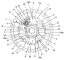
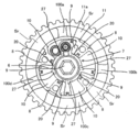
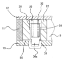
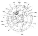
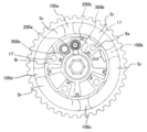
- FIG. 1 is an exploded perspective view showing a first embodiment of a valve timing control device according to the present invention. It is an effect explanatory view showing the state where valve timing by a 1st embodiment was controlled to the retard side. It is an effect explanatory view showing the state where valve timing by a 1st embodiment was controlled to the advance side. It is a longitudinal cross-sectional view which shows the locked state by the locking mechanism with which 1st Embodiment is provided. It is action explanatory drawing which shows the state which controlled the valve timing by 2nd Embodiment of this invention to the retard side.
- valve timing control apparatus for an internal combustion engine according to a first embodiment of the present invention will be described in detail with reference to FIGS.
- the valve timing control device shown in FIG. 1 is disposed on the upper surface of the cylinder head of the engine and controls the opening / closing timing of the engine valve.
- a timing pulley 1 that is rotationally driven via a timing belt by a crankshaft that is rotated by the operation of a piston of an engine (not shown), a camshaft 2 that is provided to be rotatable relative to the timing pulley 1, and a timing
- a phase conversion mechanism 3 disposed between the pulley 1 and the camshaft 2 for converting the relative rotational positions of the two and a hydraulic circuit mechanism 4 for supplying hydraulic oil for operating the phase conversion mechanism 3 is provided. ing.
- the camshaft 2 is a camshaft on the intake side
- the phase conversion mechanism 3 controls the opening / closing timing of the intake valve.
- the phase conversion mechanism 3 can be attached to the camshaft on the exhaust side to control the opening / closing timing of the exhaust valve, and further, the opening / closing timing of both the intake valve and the exhaust valve can be controlled.
- the camshaft 2 is rotatably supported by a cylinder head (not shown) via a cam bearing, and a plurality of drive cams for opening the intake valve via a valve lifter are integrally provided at predetermined positions on the outer peripheral surface.
- a female screw hole 2b into which a cam bolt 6 to be described later is screwed is formed in the inner axial direction of the one end 2a.
- the phase conversion mechanism 3 is fixed in the axial direction by a cylindrical housing 5 disposed at one end of the camshaft 2 and a cam bolt 6 at one end of the camshaft 2.
- a vane member 7 rotatably accommodated in the housing 5, four shoes 8 formed on the inner peripheral surface of the housing 5, and four vanes 22 to 25 of the vane member 7 are formed.
- four retard hydraulic chambers 9 and advanced hydraulic chambers 10 are provided.
- the housing 5 includes a substantially cylindrical housing body 11, and a front plate 12 and a rear plate 13 that open the front and rear opening ends of the housing body 11.
- the housing body 11, the front plate 12, and the rear plate 13 are 4 in number.
- the bolts 14 are integrally coupled together by tightening from the axial direction.
- each shoe 8 is formed in a substantially U shape, and a substantially U-shaped seal member 28 slidably contacting the peripheral surface 7c of the vane member 7 in a seal groove 57 formed in the axial direction at each tip portion. Is inserted. Further, bolt insertion holes 17 through which the respective bolts 14 are inserted are formed in the inner axial direction on the base portion side of each shoe 8.
- the front plate 12 is formed in a relatively thin disk shape, and has a large-diameter hole 12a through which the cam bolt 6 is inserted. Further, four bolt holes 12c through which the respective bolts 14 are inserted are formed at substantially equal positions in the circumferential direction on the outer peripheral side.
- the rear plate 13 is provided with a support hole 19 that is rotatably supported by the camshaft 2 being inserted in the center. Further, female screw holes 13a into which the male screws at the front end portions of the bolts 14 are screwed are formed at substantially equal positions in the circumferential direction on the outer peripheral side. A positioning pin 13b is provided on a part of the rear plate 13, and engages with a positioning hole (not shown) provided in the housing 5 to position the housing 5 and the rear plate 13.
- the vane member 7 includes a vane rotor 21 fixed to the one end portion 2 a of the camshaft 2 from the axial direction by a cam bolt 6 communicating with the insertion hole 7 a from the axial direction, and an outer periphery of the vane rotor 21. It is composed of four vanes 22 to 25 projecting radially at substantially equal intervals in the circumferential direction of the surface.
- the vane rotor 21 is rotatably supported while sliding on a seal member 28 fitted on the upper surface of the tip end of each shoe 8 and also in the inner radial direction as shown in FIGS. 2, 3, and 4.
- Four retarded-side oil holes 20 communicating with the angular hydraulic chamber 9 and four advanced-side oil grooves 27 communicating with each advanced hydraulic chamber 10 are formed at the rear plate side end.
- Each of the vanes 22 to 25 is disposed between the shoes 8 and is substantially axially slidably in contact with the inner peripheral surface 11a of the housing body 11 in a seal groove 57 formed in the axial direction on each tip surface.
- a “U” -shaped sealing member 28 is fitted.
- Each of the vanes 22 to 25 has different circumferential widths as shown in FIGS. 2, 3, and 4, and one vane 22 is formed to have a maximum width. It can be accommodated.
- the remaining vanes 23 to 25 may have the same width or may be different. However, it is effective to make the vane 24 located on the opposite side of the vane 22 thicker than the vanes 23 and 25 in order to balance the weight with respect to the vane 22.
- a lock mechanism for restricting free rotation of the vane member 7 is provided between the vane 22 having the maximum width and the rear plate 13.
- This lock mechanism is slidably accommodated in a sliding hole 29 formed through the vane 22 in the direction of the internal axis, and is provided with a lock piston 30 slidable with respect to the rear plate 13 side, and a rear plate. 13 is formed at a predetermined position in the circumferential direction of the inner end face, and the front end 30a of the lock piston 30 advances and engages, or retreats and the lock hole 31 is released, and the engine is in a starting state. Accordingly, the lock piston 30 is configured to be engaged with or disengaged from the lock hole 31.
- the lock piston 30 is formed in a cylindrical pin shape and the tip portion 30 a is formed in a substantially conical shape, so that the lock piston 30 is easily engaged in the lock hole 31.
- a short notch groove 7b is formed on the front plate 12 side of the sliding hole 29, and the notch groove 7b communicates with the outside air, so that the rotation range of the vane member 7 is achieved. Therefore, it always functions as an air vent for ensuring good sliding of the lock piston 30.
- the lock hole 31 is a retard angle at which the relative conversion angle between the housing 5 and the vane member 7 becomes an optimal conversion angle when the engine is started. It is set to be the position on the side or advance side.
- the engagement / disengagement mechanism includes a coil spring 32 that is elastically mounted between the rear end portion of the lock piston 30 and the inner end surface of the front plate 12 and urges the lock piston 30 in the advancing direction.
- the release hydraulic circuits 54 and 55 are configured to supply hydraulic pressure into the lock hole 31 to move the lock piston 30 backward, and the release hydraulic circuits 54 and 55 are provided with the retard oil chamber 9 and the advance oil chamber.
- the hydraulic oil selectively supplied to 10 is introduced through a predetermined oil hole.
- the hydraulic circuit mechanism 4 selectively supplies hydraulic oil to the advance oil chamber 9 and the retard oil chamber 10 or operates in the advance oil chamber 9 and the retard oil chamber 10.
- each retard angle side passage 36 communicating with each retard angle side oil hole 20, each advance angle side passage 37 communicating with each advance angle side oil groove 27, and each of these
- An oil pump 39 that selectively supplies hydraulic oil to the passages 36 and 37 via an electromagnetic switching valve 38, and a drain that selectively communicates with the retard side passage 36 and the advance side passage 37 via the electromagnetic switching valve 38.
- a passage 40 The oil pump 39 sucks the hydraulic oil from the hydraulic oil container (oil pan) 41, and the drain passage 40 returns the hydraulic oil to the hydraulic oil container 41.
- the retard side passage 36 and the advance side passage 37 are connected to each oil groove 27 via oil passage holes 36a, 37a and groove grooves 36b, 37b formed in the camshaft 2 along the radial direction and the axial direction.
- the oil holes 20 communicate with each other.
- the electromagnetic switching valve 38 is a two-way valve, and selectively switches between the retard side passage 36, the advance side passage 37, the discharge passage 39a of the oil pump 39, and the drain passage 40 by an output signal from a controller (not shown). It is supposed to be.
- the controller detects the current engine operating state by inputting operation information signals from various sensors such as a crank angle sensor, an air flow meter, a water temperature sensor, a throttle valve opening sensor, etc., which are not shown in the figure.
- a control current is output to the electromagnetic coil of the electromagnetic switching valve 38 in accordance with the engine operating state.
- the valve timing control device configured as described above performs the following operations. First, when the engine is started, as shown in FIG. 3, the lock piston 30 is previously engaged in the lock hole 31 to restrain the vane member 7 at a position on the retard side optimum for starting. For this reason, when start-up is started by turning on the ignition switch, good startability is obtained by smooth cranking.
- the controller applies a control current to the electromagnetic coil of the electromagnetic switching valve 38.
- the intake valve is controlled from the discharge passage 39a of the oil pump 39, the advance side passage 37 is communicated with the retard angle side passage 36 and the drain passage 40 at the same time.
- the control current is cut off from the controller to the electromagnetic switching valve 38, and the discharge passage 39a and the retard side passage 36 are communicated, and at the same time, the advance side passage 37 and the drain are connected.
- the passage 40 is communicated.
- the hydraulic oil in the advance oil chamber 10 is discharged and becomes low pressure, and the hydraulic oil is supplied into the retard oil chamber 9 and the inside becomes high pressure.
- the lock piston 30 is maintained in a state of coming out of the lock hole 31. Therefore, as shown in FIG. 3, the vane member 7 rotates counterclockwise with respect to the housing 5 to convert the relative rotation phase with respect to the timing pulley 1 to the retard side.
- the present embodiment is characterized in that the following configuration is added.
- the outer shape of the housing 5 is a substantially circular shape
- the outer shape of the timing pulley 1 is also formed in a substantially annular shape in accordance with this. External teeth that mesh with the timing belt are formed on the outer peripheral side of the timing pulley.
- the timing pulley 1 is located outside the outer peripheral part of the housing 5, and the housing 5 and the timing pulley 1 are divided and separated by a predetermined distance L (see FIG. 3).
- the inner peripheral side of the timing pulley 1 and the outer peripheral side of the housing body 11 are combined and integrated by four connecting beam portions 100a to 100d. Accordingly, the housing body 11 and the timing pulley 1 are not coupled between the circumferential intervals of the coupling beam portions 100a to 100d, and a space region Sr is formed.
- the housing main body 11, the timing pulley 1, and the coupling beam portions 100a to 100d can be integrally formed by a processing method such as cutting, forging, or drawing aluminum or aluminum alloy. Furthermore, it can be integrally formed by sintering metal powder such as iron powder, aluminum powder, or iron-based metal powder. It is also possible to integrally mold with resin.
- iron-based metal powder is sintered to integrally form the housing body 5, the timing pulley 1, and the connecting beam portions 100a to 100d.
- the iron-based metal powder is sintered and manufactured in this way, it is possible to easily make components of the valve timing control device having a complicated shape as in the present embodiment.
- the timing pulley 1 is disposed so as to overlap the outer periphery of the housing body 11. That is, the timing pulley 1 is positioned between the projection surface obtained by extending the outer surface of the front plate 12 and the outer surface of the rear plate 13 in the radial direction in a state where the front plate 12, the housing body 11, and the rear plate 13 are assembled. It is like that.
- the length of the timing pulley 1 in the axial direction can be ignored because the timing pulley 1 is positioned between the outer surface of the front plate 12 and the projection surface obtained by extending the outer surface of the rear plate 13 in the radial direction. Accordingly, the axial length of the valve timing control device can be shortened.
- the timing pulley 1 and the housing body 11 are integrally formed. Therefore, the axial length Lt of the timing pulley 1 and the axial length Lh of the housing body 11 are as follows. It is the same length. Thus, when the length Lt of the timing pulley 1 and the length Lh of the housing body 11 are made the same, the mold structure in the case of sintering can be simplified.
- the axial lengths of the four coupling beam portions 100a to 100d connecting the inner peripheral side of the timing pulley 1 and the outer peripheral side of the housing main body 11 are the length Lt of the timing pulley 1 and the length Lh of the housing main body 11. It may be the same. Thereby, the mold structure in the case of sintering can be simplified.
- the length of the four coupling beam portions 100a to 100d in the axial direction is shorter than the length Lt of the timing pulley 1 and the length Lh of the housing body 11.
- the weight of the coupling beam portions 100a to 100d can be reduced, and finally the weight of the valve timing control device can be reduced.
- the coupling beam portions 100a to 100d are coupled in the vicinity of the central portion in the axial direction of the inner peripheral portion of the timing pulley 1 and the outer peripheral portion of the housing main body 11, and the periphery of the joint portion is formed in an arc shape to reduce stress concentration. It has come to be.
- the connecting beam portions 100a to 100d are arranged in a region between the positions where the shoes 8 are arranged, and are connected to a thin portion of the housing body 11. Since the four shoes 8 have a large cross-sectional area, sufficient mechanical strength is ensured. However, since the outer peripheral area between the four shoes 8 is thin, the mechanical strength is not sufficient. It was thick.
- the coupling beam portions 100a to 100d are provided in the outer peripheral region between the four shoes 8, the mechanical strength of the outer peripheral region between the four shoes 8 is increased by the coupling beam portions 100a to 100d. Can do. Therefore, since the thickness of the outer peripheral part of the housing main body 11 can be reduced, the effect that the diameter of the housing 5 can be reduced or the weight can be reduced can be achieved.
- the weight distribution between each shoe 8 and the coupling beam portions 100a to 100d is good.
- the overall weight can be made uniform with the timing pulley 1, the front plate 12, the housing body 11, and the rear plate 13 assembled, and the weight balance can be improved.
- the maximum width vane 22 on which the lock piston 30 is disposed is heavier than the other vanes 23 to 25, so that the timing pulley 1, the front plate 12, the housing body 11, and the rear plate 13 are assembled.
- the center of gravity on the plane orthogonal to the axial direction is always close to the maximum width vane 22 side. If the center of gravity is too close to one side, the rotational movement is hindered, so it is necessary to bring the center of gravity as close to the center of rotation as possible.
- the coupling beam portions 100b and 100d are arranged close to the coupling beam portion 100c side to perform overlaying. Therefore, the center of gravity can be as close as possible to the center of rotation, and an increase in weight can be suppressed.
- the coupling beam portions 100b to 100d can be provided with a balance improving function for improving the weight balance in addition to the mechanical reinforcing function of the outer peripheral portion of the housing body 11.
- the timing pulley 1 has a problem that the area of the timing pulley 1 increases in shape and weight with respect to the housing 5. For this reason, in this embodiment, the coupling beam portions 100a to 100d are arranged at predetermined intervals in the circumferential direction to form the space region Sr. As a result, the weight of the timing pulley 1 can be reduced.
- timing pulley 1 and the housing body 11 are integrally formed by the coupling beam portions 100a to 100d, there is no need to couple and fix the timing pulley and the rear plate with bolts as in Patent Document 1, and the number of parts is reduced. There is no problem of increasing the number of assembly steps associated with this.
- valve timing control device when the valve timing control device is assembled to the camshaft, since the housing 5 and the timing pulley 1 are integrated, the timing pulley 1 can be grasped and assembled to the camshaft, so that centering during assembly becomes easy. There is also an effect.
- the timing pulley is arranged at an interval on the outer peripheral portion of the housing forming the advance oil chamber and the retard oil chamber, and between the outer peripheral portion of the housing and the timing pulley.
- the outer periphery of the housing and the timing pulley are connected and integrally formed by the coupling beam, the outer periphery of the housing is reinforced by the coupling beam, so that the thickness of the outer periphery of the housing is reduced. can do.
- valve timing control device according to a second embodiment of the present invention will be described with reference to FIGS. Since the present embodiment is basically the same as the first embodiment, the description of the same operation and effect as the first embodiment will be omitted.
- FIG. 6 shows the most retarded angle state
- FIG. 7 shows the most advanced angle state
- a retard side stopper surface 200a and an advance side stopper surface 200b are formed on both side surfaces of the maximum width vane 22.
- a retarded-side contact surface 300a is formed on the wall surface of the shoe 8r that the retarded-side stopper surface 200a collides with and comes into contact with, while the advanced-angle side stopper surface 200b collides with and comes into contact with the wall surface of the shoe 8a with which the advanced-angle side stopper surface 200b comes into contact.
- a contact surface 300b is formed.
- the retard side stopper surface 200a of the maximum width vane 22 is controlled to the retard side contact surface 300a of the shoe 8r when controlled to the most retarded position shown in FIG. Collide with strong force.
- deformation occurs such that the outer peripheral portion of the housing body 11 on the side opposite to the retard side contact surface 300a rotates around the bolt 14 of the bolt insertion hole 17 provided in the shoe 8r.
- the advanced side stopper surface 200b of the maximum width vane 22 becomes the advanced side contact surface of the shoe 8a. It collides with 300b with a strong force. At this time, deformation occurs such that the outer peripheral portion of the housing body 11 opposite to the advance side contact surface 300b rotates around the bolt 14 of the bolt insertion hole 17 provided in the shoe 8a.
- a coupling beam portion 100d is provided in the vicinity of the connection region Cr1 of the space region Sr close to the opposite side surface of the retard side contact surface 300a of the shoe 8r.
- the shoe 8r is provided on the shoe 8r side with respect to the center in the circumferential direction between the side surface 300c opposite to the retarding-side contact surface 300a and the shoe 8c facing the 300c in the circumferential direction.
- the connecting beam portion 00d may be disposed so as to partially overlap the side surface opposite to the retard side contact surface 200b of the shoe 8r when viewed in the circumferential direction.
- a coupling beam portion 100b is provided in the vicinity of the connection region Cr2 of the space region Sr close to the side surface opposite to the advance side contact surface 300b of the shoe 8a.
- the shoe 8a is provided closer to the shoe 8a than the center in the circumferential direction between the side surface 300d opposite to the advance side contact surface 300b and the shoe 8d facing the 300d in the circumferential direction.
- the coupling beam portion 00b may be disposed so as to partially overlap the side surface opposite to the advance side contact surface 300b of the shoe 8a when viewed in the circumferential direction.
- the retarded-side stopper surface 200a of the maximum width vane 22 collides with the retarded-side contact surface 300a of the shoe 8r with a strong force. At this time, deformation occurs such that the outer peripheral portion of the housing body 11 on the opposite side of the retarded contact surface 300a rotates around the bolt 14 of the bolt insertion hole 17 provided in the shoe 8r. It is received by the coupling beam portion 100d, and deformation of the outer peripheral portion of the housing body 11 is suppressed.
- the advanced side stopper surface 200b of the maximum width vane 22 collides with the advanced side contact surface 300b of the shoe 8a with a strong force. At this time, deformation occurs such that the outer peripheral portion of the housing body 11 on the side opposite to the advance contact surface 300b rotates around the bolt 14 of the bolt insertion hole 17 provided in the shoe 8a. Is received by the coupling beam portion 100b, and deformation of the outer peripheral portion of the housing body 11 is suppressed.
- valve timing control device according to a third embodiment of the present invention will be described with reference to FIG. Since the present embodiment is basically the same as the first embodiment, the description of the same operation and effect as the first embodiment will be omitted.
- coupling beam portions 100a to 100d are arranged at positions where each shoe 8 formed on the housing body 11 and the timing pulley 1 face each other.
- the coupling beam portions 100a to 100d are provided side by side on the outer side in the radial direction of each shoe 8.
- the bolts 14 are inserted into the bolt insertion holes 17 of the shoes 8, and the front plate 12, the housing body 11, and the rear plate 13 are firmly tightened. For this reason, in order to smoothly rotate the vanes 22 to 25 disposed therein, it is necessary to appropriately take side clearances between the vanes 22 to 25 and the front plate 12 and the rear plate 13.
- the coupling beam portions 100a to 100d are arranged at positions where the shoes 8 formed on the housing body 11 and the timing pulley 1 face each other.
- the shoes 8 and the coupling beam portions 100a to 100d are brought close to each other, so that the mechanical strength of the portions increases, and the outer peripheral portion of the housing body 11 remains even if the tightening axial force of the bolt 14 is increased. It will not easily deform. As a result, the risk that the outer peripheral portion of the housing main body 11 is deformed and the vanes 22 to 25 come into contact with the front plate 12 and the rear plate 13 can be suppressed.
- each shoe 8 and the coupling beam portions 100a to 100d are close to each other. Therefore, when the housing body 11 and the coupling beam portions 100a to 100d are integrated by sintering, each shoe 8 and the coupling beam portions 100a to 100d are integrated. Since the portions 100a to 100d are close to each other and have a large volume, a large amount of metal powder can be filled, and the balance of the sintered density when integrally formed is improved. This makes it easy to ensure the strength.
- a coupling beam portion is provided between the two shoes.
- the coupling beam portion is provided side by side on the radial direction of each shoe.
- a combination beam portion may be provided in combination with the third embodiment.
- the housing is composed of a housing main body, a front plate, and a rear plate, but the housing main body and the front plate or the rear plate may be integrally formed to form the housing main body.
- the timing pulley is disposed at an interval on the outer peripheral portion of the housing forming the advance oil chamber and the retard oil chamber, and the outer periphery of the housing and the timing pulley are arranged. It was set as the structure which couple
- the outer peripheral portion of the housing and the timing pulley are connected by the connecting beam portion and integrally formed, the outer peripheral portion of the housing is reinforced by the connecting beam portion, so the thickness of the outer peripheral portion of the housing is reduced. be able to.
- this invention is not limited to the above-mentioned Example, Various modifications are included.
- the above-described embodiments have been described in detail for easy understanding of the present invention, and are not necessarily limited to those having all the configurations described.
- a part of the configuration of one embodiment can be replaced with the configuration of another embodiment, and the configuration of another embodiment can be added to the configuration of one embodiment.
- SYMBOLS 1 Timing pulley, 2 ... Cam shaft, 3 ... Phase conversion mechanism, 4 ... Hydraulic circuit mechanism, 5 ... Housing, 6 ... Cam bolt, 7 ... Vane member, 8 ... Shoe, 9 ... Retarded hydraulic chamber, 10 ... Advance angle Hydraulic chamber, 11 ... housing body, 12 ... front plate, 13 ... rear plate, 14 ... bolt, 21 ... vane rotor, 22-25 ... vane, 100a-100d ... coupled beam.
Landscapes
- Engineering & Computer Science (AREA)
- Mechanical Engineering (AREA)
- General Engineering & Computer Science (AREA)
- Valve Device For Special Equipments (AREA)
Abstract
軸方向の長さを短縮すると共に、ハウジングの肉厚を薄くすることができる新規なバルブタイミング制御装置を提供する。 内燃機関のバルブタイミング制御装置は、クランクシャフトからタイミングベルトを介して回転力が伝達されるタイミングプーリーと、タイミングプーリーによって回転され、内周面に複数のシューが設けられたハウジングと、ハウジングの内部に相対回転自在に収容されている共に、カムシャフトと同期回転するベーンロータであって、複数のシューの各々と協働してハウジング内部に遅角油室と進角油室とを形成するベーンを有するベーンロータと、を備える。ハウジングの外周部とタイミングプーリーの内周部との間に所定の間隔が設けるられ、ハウジングのハウジング本体の外周部と、タイミングプーリーの内周部と、が周方向に間隔を置いて複数の結合梁部によって結合され、ハウジング本体、タイミングプーリー及び複数の結合梁部は、一体的に形成される。
Description
本発明は、内燃機関の吸気弁や排気弁である機関弁の開閉タイミングを運転状態に応じて可変制御するバルブタイミング制御装置及びこれを使用した内燃機関に関するものである。
従来のバルブタイミング制御装置としてはベーンタイプのものが良く知られている。このベーンタイプのバルブタイミング制御装置は、クランク軸から回転力が伝達されるハウジングと、このハウジングの内部に回転自在に収容されて、カムシャフトの端部に固定されたベーン部材とを備え、ハウジングの内周面に直径方向から互いに内方へ突出された複数のシューとベーン部材の複数のベーンとの間に進角油室と遅角油室が形成されている。
そして、機関運転状態に応じて進角油室と遅角油室のいずれか一方に、電動ポンプ或いは機械ポンプから吐出された作動油を選択的に供給し、かかる作動油の駆動油圧によりベーン部材を正逆回転させて、ベーンを所定位置に保持することによって、吸気弁や排気弁の開閉タイミングを可変制御するようにしている。
このようなベーンタイプのバルブタイミング制御装置は、エンジンルーム内の内燃機関に装着されるので小型にする必要があり、バルブタイミング装置の軸方向の短縮化もその一つである。従来のバルブタイミング制御装置では、タイミングプーリーと、進角油室や遅角油室を形成するハウジングとは軸方向に並べて配置されているので軸方向の短縮化ができないものであった。
そして、このバルブタイミング制御装置の軸方向の短縮化という要請に応えるために種々の技術が開発、提案されている。例えば、特開2012-132404号公報(特許文献1)においては、ハウジングの外周側に一部が重なるように環状のタイミングプーリーを配置すると共に、タイミングプーリーの内周側に等間隔に内側に突き出た突出結合部を形成し、進角油室や遅角油室を形成するためハウジングに固定されたリアプレートに突出結合部をボルトによって結合、固定したバルブタイミング制御装置が提案されている。
ところで、特許文献1に記載のバルブタイミング制御装置においては、タイミングプーリーは突出結合部によってリアプレートに固定される構造とされている。このため、ハウジングの外周部は従来の構成と同様であるので、ハウジングのシューにベーンが当接した際のハウジングの変形を抑えるため、ハウジングの外周部の肉厚を厚くする必要があった。このため、ハウジングが大径化する、重量が増加するといった課題が依然として残っている。
本発明の目的は、ハウジングの肉厚を薄くすることができる新規なバルブタイミング制御装置及びこれを使用した内燃機関を提供することにある。
本発明の一実施形態では、進角油室や遅角油室を形成するハウジングの外周部に所定の間隔を置いてタイミングプーリーが配置され、ハウジングのハウジング本体の外周部と、タイミングプーリーの内周部と、が周方向に間隔を置いて複数の結合梁部によって結合され、ハウジング、タイミングプーリー及び複数の結合梁部は一体的に形成されている。
本発明の一実施形態によれば、ハウジングの外周部とタイミングプーリーの内周部の間を結合梁部で繋いで一体成形したことから、ハウジングの外周部が結合梁部により補強されるためハウジングの外周部の肉厚を薄くすることができる。
本発明の実施形態について図面を用いて詳細に説明するが、本発明は以下の実施形態に限定されることなく、本発明の技術的な概念の中で種々の変形例や応用例をもその範囲に含むものである。
以下、本発明の第1の実施形態になる内燃機関のバルブタイミング制御装置について図1乃至図5を用いて詳細に説明する。
図1に示すバルブタイミング制御装置は、機関のシリンダヘッドの上面に配置されて機関弁の開閉タイミングを制御するものである。そして、図示しない機関のピストンの作動によって回転するクランクシャフトにより、タイミングベルトを介して回転駆動されるタイミングプーリー1と、このタイミングプーリー1に対して相対回転可能に設けられたカムシャフト2と、タイミングプーリー1とカムシャフト2との間に配置されて、両者の相対回転位置を変換する位相変換機構3と、この位相変換機構3を作動させるための作動油を供給する油圧回路機構4とを備えている。
ここで、本実施例ではカムシャフト2は吸気側のカムシャフトであり、位相変換機構3は吸気弁の開閉タイミングを制御するものである。もちろん位相変換機構3を排気側のカムシャフトに取り付けて排気弁の開閉タイミングを制御することもでき、更には吸気弁と排気弁の両方の開閉タイミングを制御することもできるものである。
カムシャフト2は、図示しないシリンダヘッドにカム軸受を介して回転自在に支持され、外周面所定位置にバルブリフターを介して吸気弁を開作動させる複数の駆動カムが一体に設けられていると共に、一端部2aの内部軸方向に後述のカムボルト6が螺着する雌ねじ孔2bが形成されている。
図2及び至図3にあるように、位相変換機構3は、カムシャフト2の一端部に配置された円筒状のハウジング5と、カムシャフト2の一端部にカムボルト6によって軸方向から固定されたハウジング5内に回転自在に収容されたベーン部材7と、ハウジング5内に形成されて、ハウジング5の内周面に有する4つのシュー8とベーン部材7の4つのベーン22~25とによって形成された、それぞれ4つの遅角油圧室9及び進角油圧室10とを備えている。
ハウジング5は、ほぼ円筒状のハウジング本体11と、このハウジング本体11の前後開口端を開塞するフロントプレート12及びリアプレート13とを備え、このハウジング本体11とフロントプレート12、リアプレート13が4本のボルト14によって軸方向から共締めにより一体的に結合されている。
また、ハウジング本体11の内周面には、円周上のほぼ等間隔位置に4つのシュー8が一体に突設されている。この各シュー8はほぼU字形状に形成され、それぞれの先端部に軸方向に沿って形成されたシール溝57内に、ベーン部材7の周面7cに摺接するほぼコ字形状のシール部材28が嵌着されている。また、各シュー8の付け根部側の内部軸方向には、各ボルト14が挿通するボルト挿通孔17が貫通形成されている。
フロントプレート12は、図1及び図2に示すように、比較的薄肉な円板状に形成され、中央にカムボルト6が挿通する大径孔12aが穿設されている。更に、外周側の円周方向のほぼ等間隔位置には、各ボルト14が挿通する4つのボルト孔12cが貫通形成されている。
リアプレート13は、中央にカムシャフト2が挿通して回転自在に支持される支持孔19が穿設されている。また、外周側の円周方向のほぼ等間隔位置には、前記ボルト14の先端部の雄ねじが螺着する雌ねじ孔13aが形成されている。また、リアプレート13の一部には位置決めピン13bが設けられており、ハウジング5に設けた図示しない位置決め孔に係合して、ハウジングト5とリアプレート13位置決めを行っている。
ベーン部材7は、図2及び図3に示すように、挿通孔7aを軸方向から連通したカムボルト6によってカムシャフト2の一端部2aに軸方向から固定されたベーンロータ21と、このベーンロータ21の外周面の円周方向のほぼ等間隔位置に放射状に突設された4枚のベーン22~25とから構成されている。
ベーンロータ21は、各シュー8の先端部上面に嵌着されたシール部材28に摺動しつつ回転支持されていると共に、図2、図3、図4に示すように内部径方向に、各遅角油圧室9に連通する4つの遅角側油孔20と、リアプレート側端部に各進角油圧室10に連通する4つの進角側油溝27が形成されている。
各ベーン22~25は、それぞれが各シュー8の間に配置されると共に、各先端面に軸方向に形成されたシール溝57内にハウジング本体11の内周面11aに摺接する軸方向でほぼ「コ」の字形状のシール部材28が嵌着されている。また、各ベーン22~25は、図2、図3、図4に示すように、その円周方向の巾がそれぞれ異なつており、1つのベーン22が最大幅に形成され、後述のロックピストンを収容可能としている。残余のベーン23~25は同じ幅であっても良いし、異なっていても良い。ただ、ベーン22の反対側に位置しているベーン24は、ベーン22に対して重量バランスをとるため、ベーン23、25より厚くすることが有効である。
最大幅のベーン22は、ベーン部材7が図3に示すように吸気弁を制御する場合、最大反時計方向に回転した際に、その先端縁が対向するシュー8の側面に当接してそれ以上の回転を規制して、ハウジング5との相対回転変換角度を調整するようになっている。また、最大幅のベーン22は、ベーン部材7が図4に示すように吸気弁を制御する場合、最大時計方向に回転した際に、対向するシュー8の側面に当節してそれ以上の回転を規制するための凸部200bを有している。
更に、最大幅のベーン22とリアプレート13との間には、ベーン部材7の自由な回転を拘束するロック機構が設けられている。このロック機構は、ベーン22の内部軸方向に貫通形成された摺動用孔29内に摺動自在に収容されて、リアプレート13側に対して進退自在に設けられたロックピストン30と、リアプレート13の内端面円周方向の所定位置に形成されて、ロックピストン30の先端部30aが進出して係合し、あるいは後退して係合が解除されるロック孔31と、機関の始動状態に応じてロックビストン30をロック孔31に係合あるいは係合を解除する係脱機構とから構成されている。
図5に示すように、ロックピストン30は、円筒のピン状に形成されると共に先端部30aがほぼ円錐状に形成されて、ロック孔31内に係合し易い形状となっている。尚、図1にあるように摺動用孔29のフロントプレート12側には、短形状の切欠き溝7bが形成され、この切欠き溝7bが外気と連通することにより、ベーン部材7の回転範囲で常にロックピストン30の良好な摺動を確保するための空気抜きとして機能するようになっている。
また、ロック孔31は、図3、図4に示すように、ロックピストン30が係合した場合には、ハウジング5とベーン部材7の相対変換角度が機関始動時に最適な変換角度となる遅角側もしくは進角側の位置となるように設定されている。
図5にあるように、係脱機構は、ロックピストン30の後端部とフロントプレート12の内端面との間に弾装されて、ロックピストン30の進出方向へ付勢するコイルスプリング32と、ロック孔31内に油圧を供給してロックピストン30を後退させる解除用油圧回路54、55とから構成されており、この解除用油圧回路54、55は、遅角油室9と進角油室10にそれぞれ選択的に供給された作動油が所定の油孔を介して導入されるようになっている。
図1に戻って、油圧回路機構4は、進角油室9、遅角油室10に対して作動油を選択的に供給し、或いは進角油室9、遅角油室10内の作動油を排出するもので、吸気弁を制御する場合、各遅角側油孔20に連通する遅角側通路36と、各進角側油溝27に連通する進角側通路37と、この各通路36、37に電磁切換弁38を介して作動油を選択的に供給するオイルポンプ39と、遅角側通路36、進角側通路37に電磁切換弁38を介して選択的に連通するドレン通路40とを備えている。オイルポンプ39は作動油容器(オイルパン)41から作動油を吸入し、ドレン通路40は作動油容器41に作動油を戻すものである。
遅角側通路36、進角側通路37は、カムシャフト2の内部に径方向及び軸方向に沿って形成された油通路孔36a、37a及びグルーブ溝36b、37bを介して各油溝27と各油孔20に連通している。
電磁切換弁38は、2方向弁であって、図示しないコントローラからの出力信号によって遅角側通路36、進角側通路37とオイルボンプ39の吐出通路39a及びドレン通路40とを選択的に切り換え制御するようになっている。
コントローラは、内部のコンピュータが図示しないクランク角センサやエアーフローメータ、水温センサ、スロットルバルブ開度センサ等の各種センサ類からの動作情報信号を入力して現在の機関運転状態を検出すると共に、かかる機関運転状態に応じて電磁切換弁38の電磁コイルに制御電流を出力するようになっている。
以上のような構成のバルブタイミング制御装置においては、次のような動作を行うものである。先ず、機関始動時は、図3に示すように、予めロックピストン30がロック孔31内に係入して、ベーン部材7を始動に最適な遅角側の位置に拘束している。このため、イグニッションスイッチをオン操作して始動が開始されると、スムーズなクランキングによって良好な始動性が得られる。
そして、機関始動後の所定の負荷領域では、コントローラが電磁切換弁38の電磁コイルに制御電流を通電する。これによって、オイルポンプ39の吐出通路39aから吸気弁を制御する場合、進角側通路37を連通させると同時に、遅角側通路36とドレン通路40とを連通させる。
このため、オイルポンプ39から吐出された作動油が、進角側通路37を介して進角油室10内に流入して、この進角油室10が高圧になる一方、遅角油室9内の作動油が遅角側通路36を通ってドレン通路40からオイルバン41内に排出されて、遅角油室9内が低圧になる。
このとき、進角油室10内に流入した作動油がロック孔31内に流入して、ロックピストン30を後退動させてロック孔31から抜け出させる。これにより、ベーン部材7は、自由な回転が確保される。したがつて、進角油室10の容積の拡大に伴い、ベーン部材7は図4に示すように、時計方向に回転する。したがつて、カムシャフト2は、タイミングプーリー1に対して相対回転角度が進角側に変換される。
一方、機関が別の負荷領域に移行した場合は、コントローラから電磁切換弁38に制御電流が遮断されて、吐出通路39aと遅角側通路36を連通させると同時に、進角側通路37とドレン通路40を連通させる。これにより、進角油室10内の作動油が排出されて低圧になると共に、遅角油室9内に作動油が供給されて内部が高圧になる。このとき、遅角油室9からロック孔31内に油圧が供給されることから、ロックピストン30はロック孔31から抜け出した状態が維持される。このため、ベーン部材7は、図3に示すように、ハウジング5に対して反時計方向へ回転してタイミングプーリー1に対する相対回動位相を遅角側に変換する。
以上のようなバルブタイミング制御装置において、本実施例では次に述べる構成を付加しているところが特徴となっている。
図2、図3に示しているように、ハウジング5の外形形状は略円形状であり、タイミングプーリー1の外形形状もこれに合わせて略円環状に形成されている。タイミングプーリーの外周側には、タイミングベルトに噛み合う外歯が形成されている。そして、ハウジング5の外周部の外側にはタイミングプーリー1が位置しており、ハウジング5とタイミングプーリー1は分割されて所定の距離L(図3を参照)を置いて離間されている。
タイミングプーリー1の内周側とハウジング本体11の外周側は、4本の結合梁部100a~結合梁部100dによって結合されて一体化されている。したがって、各結合梁部100a~結合梁部100dの周方向の間隔の間は、ハウジング本体11とタイミングプーリー1は結合されず、空間領域Srが形成されている。
ハウジング本体11、タイミングプーリー1及び結合梁部100a~100dはアルミニウム、アルミ合金等を切削、或いは鍛造、或いは引き抜き等の加工法によって一体的に形成することができる。更には、金属粉、例えば鉄粉、アルミ粉、或いは鉄系の金属粉を焼結して一体的に形成することができる。また、樹脂により一体成形することも可能である。
本実施例では鉄系の金属粉を焼結してハウジング本体5、タイミングプーリー1及び結合梁部100a~100dを一体的に形成している。このように鉄系の金属粉を焼結して製作すると、本実施例のような複雑な形状のバルブタイミング制御装置の構成部品を容易に作ることができる。
図1にあるように、タイミングプーリー1はハウジング本体11の外周部の外側に重なるように配置されている。つまり、タイミングプーリー1は、フロントプレート12、ハウジング本体11、リアプレート13を組み付けた状態で、フロントプレート12の外側面とリアプレート13の外側面を半径方向に延長した投影面の間に位置するようになっている。
したがって、タイミングプーリー1の軸方向の長さは、タイミングプーリー1がフロントプレート12の外側面とリアプレート13の外側面を半径方向に延長した投影面の間に位置するため無視することができ、この分バルブタイミング制御装置の軸方向の長さを短縮することができる。
本実施例では、図1に示すようにタイミングプーリー1とハウジング本体11とは一体的に形成されるため、タイミングプーリー1の軸方向の長さLtとハウジング本体11の軸方向の長さLhは同じ長さとなっている。このように、タイミングプーリー1の長さLtとハウジング本体11の長さLhを同じ長さにすると、焼結する場合の型構造を簡単にすることができる。
また、タイミングプーリー1の内周側とハウジング本体11の外周側をつなぐ4本の結合梁部100a~100dの軸方向の長さは、タイミングプーリー1の長さLtとハウジング本体11の長さLhと同じにしても良い。これによって、焼結する場合の型構造を簡単にすることができる。
一方、本実施例では、4本の結合梁部100a~100dの軸方向の長さは、タイミングプーリー1の長さLtとハウジング本体11の長さLhより短くされている。このようにすると、結合梁部100a~100dによる重量を少なくでき、最終的にはバルブタイミング制御装置の出来上がりの重量を低減できる効果がある。更に、結合梁部100a~100dは、タイミングプーリー1の内周部とハウジング本体11の外周部の軸方向中央部付近で結合されており、その結合部周辺は弧状になって応力の集中が緩和されるようになっている。
図3、図4にある通り、結合梁部100a~100dは、各シュー8が配置された位置の間の領域に配置され、ハウジング本体11の肉厚の薄い部分に結合されている。4つのシュー8は断面積が大きいので機械強度も充分確保されているが、4つのシュー8の間の外周領域は肉厚が薄いので機械強度が充分でなく、従来ではこの領域の肉厚を厚くしていた。
一方、本実施例では、4つのシュー8の間の外周領域に結合梁部100a~100dを設けたので、結合梁部100a~100dによって4つのシュー8の間の外周領域の機械強度を高めることができる。したがって、ハウジング本体11の外周部の肉厚を薄くできるので、ハウジング5を小径化できる、或いは重量を低減できるといった効果を奏することができる。
本実施例では、空間領域Srに挟まれた、4つのシュー8の夫々の間に4つの結合梁部100a~100dを設けたので、各シュー8と結合梁部100a~100dの重量配分が良くなり、タイミングプーリー1、フロントプレート12、ハウジング本体11、及びリアプレート13を組み付けた状態で全体的な重量の均一化が図れ、重量バランスを向上できるようになる。
また、一般的にロックピストン30が配置される最大幅ベーン22は他のベーン23~25に比べて重量が重いため、タイミングプーリー1、フロントプレート12、ハウジング本体11、リアプレート13を組み付けた状態で、軸方向と直交する平面上の重心は必ず最大幅ベーン22側に寄ることになる。重心が一方側に寄りすぎると回転運動の妨げになるため、重心を回転中心にできるだけ寄せる必要がある。
これの対策としては、最大幅ベーン22に対向する位置(最大幅ベーン22の回転中心に対して反対側の位置)に肉盛りを設けることが考えられるが、このような構造にすると、肉盛りによって総重量が重くなるという課題が生じる。
これに対して本実施例では、結合梁部100cをほぼ反対側に配置することに加えて、結合梁部100b、100dを結合梁部100c側に寄せて配置することで、肉盛りを行うことなく重心を回転中心にできるだけ近づけることができ、重量の増加を抑制することができる。このように、結合梁部100b~100dには、ハウジング本体11の外周部の機械的な補強機能の他に、重量バランスを向上するバランス向上機能を持たせることができるようになる。
更に、タイミングプーリー1は、ハウジング5に対して形状的に面積が大きくなり重量が増加するという課題がある。このため、本実施例では結合梁部100a~100dが周方向に所定間隔を置いて配置されることで空間領域Srを形成する構成としている。これによって、タイミングプーリー1の重量を軽くできるという効果を奏するようになる。
また、タイミングプーリー1とハウジング本体11を結合梁部100a~100dによって一体的に形成しているので、特許文献1のようにタイミングプーリーとリアプレートをボルトによって結合、固定する必要がなく、部品点数が増加する、これに伴う組み付け工数が増加するという課題は生じないものである。
また、バルブタイミング制御装置をカムシャフトへ組み付ける際は、ハウジング5とタイミングプーリー1が一体化されているため、タイミングプーリー1を掴んでカムシャフトに組み付けができるので組み付け時の芯出しが容易となる効果も奏する。
以上述べた通り、本実施例によれば、進角油室や遅角油室を形成するハウジングの外周部に間隔を置いてタイミングプーリーを配置すると共に、ハウジングの外周部とタイミングプーリーとの間を周方向に間隔を置いて複数の結合梁部で結合し、更にハウジング、タイミングプーリー及び結合梁部を金属で一体成形する構成とした。
この構成によれば、ハウジングの外周部とタイミングプーリーの間を結合梁部で繋いで一体成形したことから、ハウジングの外周部が結合梁部により補強されるのでハウジングの外周部の肉厚を薄くすることができる。
次に、本発明の第2の実施形態になるバルブタイミング制御装置について図6、及び図7を用いて説明する。尚、本実施例は基本的には実施例1と同様なので、実施例1と同様の作用、効果については説明を省略する。
図6は最遅角状態を示し、図7は最進角状態を示している。最大幅ベーン22の両側面には遅角側ストッパ面200aと進角側ストッパ面200bが形成されている。そして、遅角側ストッパ面200aが衝突、当接するシュー8rの壁面には遅角側当接面300aが形成され、進角側ストッパ面200bが衝突、当接するシュー8aの壁面には進角側当接面300bが形成されている。
そして、バルブタイミング制御装置が作動している状態で、図6に示す最遅角位置に制御されると、最大幅ベーン22の遅角側ストッパ面200aはシュー8rの遅角側当接面300aに強い力で衝突する。この時に、シュー8rに設けられたボルト挿通孔17のボルト14を中心に、遅角側当接面300aとは反対側のハウジング本体11の外周部が回転するような変形が起きる。
同様に、バルブタイミング制御装置が作動している状態で、図7に示す最進角位置に制御されると、最大幅ベーン22の進角側ストッパ面200bはシュー8aの進角側当接面300bに強い力で衝突する。この時に、シュー8aに設けられたボルト挿通孔17のボルト14を中心に、進角側当接面300bとは反対側のハウジング本体11の外周部が回転するような変形が起きる。
そこで、本実施例においては、図6に示すように、シュー8rの遅角側当接面300aの反対側面に近接した空間領域Srの接続領域Cr1付近に結合梁部100dを設けている。換言すれば、シュー8rの遅角側当接面300aの反対側側面300cと、この300cと周方向において対向するシュー8cとの間の周方向中央よりもシュー8r側に設けている。尚、この場合、結合梁部00dはシュー8rの遅角側当接面200bの反対側面に、周方向で見て一部が重なるように配置しても良いものである。
同様に図7に示すように、シュー8aの進角側当接面300bの反対側面に近接した空間領域Srの接続領域Cr2付近に結合梁部100bを設けるようにしている。換言すれば、シュー8aの進角側当接面300bの反対側側面300dと、この300dと周方向において対向するシュー8dとの間の周方向中央よりもシュー8a側に設けている。この場合も、結合梁部00bはシュー8aの進角側当接面300bの反対側面に、周方向で見て一部が重なるように配置しても良いものである。
したがって、図6に示す最遅角位置に制御されると、最大幅ベーン22の遅角側ストッパ面200aはシュー8rの遅角側当接面300aに強い力で衝突する。この時に、シュー8rに設けられたボルト挿通孔17のボルト14を中心に、遅角側当接面300aの反対側のハウジング本体11の外周部が回転するような変形が起きるが、この変形は結合梁部100dによって受け止められ、ハウジング本体11の外周部の変形が抑制されるようになる。
同様に、図7に示す最進角位置に制御されると、最大幅ベーン22の進角側ストッパ面200bはシュー8aの進角側当接面300bに強い力で衝突する。この時に、シュー8aに設けられたボルト挿通孔17のボルト14を中心に、進角側当接面300bとは反対側のハウジング本体11の外周部が回転するような変形が起きるが、この変形は結合梁部100bによって受け止められ、ハウジング本体11の外周部の変形が抑制されるようになる。
次に、本発明の第3の実施形態になるバルブタイミング制御装置について図8を用いて説明する。尚、本実施例は基本的には実施例1と同様なので、実施例1と同様の作用、効果については説明を省略する。
本実施例においては、図8に示されているように、ハウジング本体11に形成した各シュー8とタイミングプーリー1とが対向する位置に結合梁部100a~100dが配置されている。つまり、矢印Aで示すように、結合梁部100a~100dが各シュー8の径方向で外側に並んで設けられている。このような構成を採用した理由は次の通りである。
各シュー8のボルト挿通孔17にはボルト14が挿通されて、フロントプレート12、ハウジング本体11及びリアプレート13が強固に締め付けられている。このため、内部に配置されるベーン22~25の回転を円滑にするためには、ベーン22~25とフロントプレート12、リアプレート13とのサイドクリアランスを適切にとる必要がある。
サイドクリアランスが大きいと、進角油室10と遅角油室9の間で作動油が漏れる恐れが大きいので、ベーン22~25とフロントプレート12、リアプレート13とのサイドクリアランスは作動油が漏れず、しかもベーン22~25が回転できる程度に狭くする必要がある。しかしながら、ボルト14の締め付け軸力を大きくし過ぎると、ハウジング5の外周部が変形してベーン22~25とフロントプレート12、リアプレート13が接触するようになる。
そこで、本実施例では、ハウジング本体11に形成した各シュー8とタイミングプーリー1とが対向する位置に結合梁部100a~100dを配置している。これによって、各シュー8と結合梁部100a~100dとが近接することになるので、この部分の機械的強度が大きくなり、ボルト14の締め付け軸力を大きくしてもハウジング本体11の外周部が容易に変形しなくなる。これによって、ハウジング本体11の外周部が変形してベーン22~25とフロントプレート12、リアプレート13が接触するという恐れを抑制することができるようになる。
また、これに関連して、各シュー8と結合梁部100a~100dとが近接するので、焼結によってハウジング本体11と結合梁部100a~100dを一体化する際に、各シュー8と結合梁部100a~100dとが近接して容積が大きくなっているので、多くの金属粉を充填できるようになり、一体形成する際の焼結密度のバランスが良くなる。これによって、強度が確保し易いものとなる。
尚、実施例1及び実施例2は2つのシューの間に結合梁部を設け、実施例3では各シューの半径方向側に並べて結合梁部を設けているが、実施例1或いは実施例2と、実施例3とを組み合わせて結合梁部を設けるようにしても良いものである。
また、ハウジングはハウジング本体、フロントプレート及びリアプレートより構成しているが、ハウジング本体とフロントプレート或いはリアプレートを一体的に形成してハウジング本体としても良い。
以上述べた通り本発明の実施形態によれば、進角油室や遅角油室を形成するハウジングの外周部に間隔を置いてタイミングプーリーを配置すると共に、ハウジングの外周部とタイミングプーリーとの間を周方向に間隔を置いて複数の結合梁部で結合し、更にハウジング、タイミングプーリー及び結合梁部を金属で一体成形した構成とした。
これによれば、ハウジングの外周部とタイミングプーリーの間を結合梁部で繋いで一体成形したことから、ハウジングの外周部が結合梁部により補強されるのでハウジングの外周部の肉厚を薄くすることができる。
尚、本発明は上記した実施例に限定されるものではなく、様々な変形例が含まれる。例えば、上記した実施例は本発明を分かりやすく説明するために詳細に説明したものであり、必ずしも説明した全ての構成を備えるものに限定されるものではない。また、ある実施例の構成の一部を他の実施例の構成に置き換えることが可能であり、また、ある実施例の構成に他の実施例の構成を加えることも可能である。また、各実施例の構成の一部について、他の構成の追加・削除・置換をすることが可能である。
本願は、2015年6月1日出願の日本特許出願番号2015-111184号に基づく優先権を主張する。2015年6月1日出願の日本特許出願番号2015-111184号の明細書、特許請求の範囲、図面及び要約書を含む全ての開示内容は、参照により全体として本願に組み込まれる。
1…タイミングプーリー、2…カムシャフト、3…位相変換機構、4…油圧回路機構、5…ハウジング、6…カムボルト、7…ベーン部材、8…シュー、9…遅角油圧室、10…進角油圧室、11…ハウジング本体、12…フロントプレート、13…リアプレート、14…ボルト、21…ベーンロータ、22~25…ベーン、100a~100d…結合梁部。
Claims (14)
- 内燃機関のバルブタイミング制御装置であって、
クランクシャフトからタイミングベルトを介して回転力が伝達されるタイミングプーリーと、
前記タイミングプーリーによって回転され、内周面に複数のシューが設けられたハウジングと、
前記ハウジングの内部に相対回転自在に収容されている共に、カムシャフトと同期回転するベーンロータであって、前記複数のシューと協働して前記ハウジング内部に遅角油室と進角油室とを形成するベーンを有するベーンロータと
を備え、
前記ハウジングの外周部と前記タイミングプーリーの内周部との間に所定の間隔が設けられ、
前記ハウジングのハウジング本体の外周部と、前記タイミングプーリーの内周部と、が周方向に間隔を置いて複数の結合梁部によって結合され、
前記ハウジング本体、前記タイミングプーリー及び前記複数の結合梁部は、一体的に形成された
内燃機関のバルブタイミング制御装置。 - 請求項1に記載の内燃機関のバルブタイミング制御装置であって、
前記ハウジング本体は、両端が開口された円筒状に形成されており、
前記開口は、フロントプレートとリアプレートとによって閉塞されている
内燃機関のバルブタイミング制御装置。 - 請求項2に記載の内燃機関のバルブタイミング制御装置であって、
前記フロントプレートと、前記リアプレートの外側面を半径方向に延長した投影面と、の間に前記タイミングプーリーが配置されている
内燃機関のバルブタイミング制御装置。 - 請求項3に記載の内燃機関のバルブタイミング制御装置であって、
前記ハウジング本体の軸方向の長さと前記タイミングプーリーの軸方向長さとは、ほぼ同じ長さに形成されている
内燃機関のバルブタイミング制御装置。 - 請求項3に記載の内燃機関のバルブタイミング制御装置であって、
前記複数の結合梁部の各々の軸方向の長さは、前記ハウジング本体及び前記タイミングプーリーの軸方向長さより短く形成されている
内燃機関のバルブタイミング制御装置。 - 請求項1乃至請求項5のいずれかに記載の内燃機関のバルブタイミング制御装置であって、
前記複数の結合梁部は、それぞれ、前記ハウジング本体の周方向において、前記複数のシューの間に形成されている
内燃機関のバルブタイミング制御装置。 - 請求項1乃至請求項5のいずれかに記載の内燃機関のバルブタイミング制御装置であって、
前記複数の結合梁部は、前記ハウジング本体に設けられた前記複数のシューの夫々の半径方向外側に並べて形成されている
内燃機関のバルブタイミング制御装置。 - 請求項6に記載の内燃機関のバルブタイミング制御装置であって、
前記ベーンに形成されたストッパ面が当接する当接面を備えた前記複数のシューの反対側面と、前記反対側面に対して周方向に対向する前記複数のシューと、の間において、周方向中央よりも前記反対側面側に前記複数の結合梁部が形成されている
内燃機関のバルブタイミング制御装置。 - 請求項1乃至請求項8のいずれかに記載の内燃機関のバルブタイミング制御装置であって、
前記タイミングプーリー、前記ハウジング本体及び前記複数の結合梁部は、鉄系の金属粉を焼結することによって一体的に形成されている
内燃機関のバルブタイミング制御装置。 - 内燃機関であって、
バルブタイミング制御装置と、
前記バルブタイミング制御装置が装着されたシリンダヘッドと
を備え、
前記バルブタイミング制御装置は、
ピストンの作動によって回転されるクランクシャフトからタイミングベルトを介して回転力が伝達されるタイミングプーリーと、
前記タイミングプーリーによって回転され、内周面に複数のシューが設けられたハウジングと、
前記ハウジングの内部に相対回転自在に収容されている共に、機関弁を開閉するカムシャフトと同期回転するベーンロータであって、前記複数のシューと協働して前記ハウジング内部に遅角油室と進角油室を形成するベーンを有するベーンロータと
を備え、
前記ハウジングの外周部と前記タイミングプーリーの内周部との間に所定の間隔が設けられ、
前記ハウジングのハウジング本体の外周部と、前記タイミングプーリーの内周部と、が周方向に間隔を置いて複数の結合梁部によって結合され、
前記ハウジング本体、前記タイミングプーリー及び前記複数の結合梁部は、一体的に形成されている
内燃機関。 - 請求項10に記載の内燃機関であって、
前記ハウジング本体は、両端が開口された円筒状に形成されており、
前記ハウジングは、前記開口を閉塞するフロントプレートとリアプレートとを備え、
前記フロントプレートと、前記リアプレートの外側面を半径方向に延長した投影面と、の間に前記タイミングプーリーが配置されている
内燃機関。 - 請求項10に記載の内燃機関であって、
前記複数の結合梁部の各々の軸方向の長さは、前記ハウジング本体及び前記タイミングプーリーの軸方向長さより短く形成されている
内燃機関。 - 請求項10乃至請求項12のいずれかに記載の内燃機関であって、
前記タイミングプーリー、前記ハウジング本体及び前記複数の結合梁部は、鉄系の金属粉を焼結することによって一体的に形成されている
内燃機関。 - 請求項10乃至請求項13のいずれかに記載の内燃機関であって、
前記複数の結合梁部は、それぞれ、前記ハウジング本体の周方向において、前記複数のシューの間に形成されている
内燃機関。
Priority Applications (3)
| Application Number | Priority Date | Filing Date | Title |
|---|---|---|---|
| DE112016002452.5T DE112016002452T5 (de) | 2015-06-01 | 2016-05-13 | Ventilzeitsteuergerät für einen Verbrennungsmotor und Verbrennungsmotor mit diesem |
| CN201680032152.7A CN107636265A (zh) | 2015-06-01 | 2016-05-13 | 内燃机的气门正时控制装置以及使用该气门正时控制装置的内燃机 |
| US15/578,334 US20180149046A1 (en) | 2015-06-01 | 2016-05-13 | Valve timing control apparatus for internal combustion engine and internal combustion engine using the same |
Applications Claiming Priority (2)
| Application Number | Priority Date | Filing Date | Title |
|---|---|---|---|
| JP2015-111184 | 2015-06-01 | ||
| JP2015111184A JP6532760B2 (ja) | 2015-06-01 | 2015-06-01 | 内燃機関のバルブタイミング制御装置及びこれを使用した内燃機関 |
Publications (1)
| Publication Number | Publication Date |
|---|---|
| WO2016194580A1 true WO2016194580A1 (ja) | 2016-12-08 |
Family
ID=57441974
Family Applications (1)
| Application Number | Title | Priority Date | Filing Date |
|---|---|---|---|
| PCT/JP2016/064262 Ceased WO2016194580A1 (ja) | 2015-06-01 | 2016-05-13 | 内燃機関のバルブタイミング制御装置及びこれを使用した内燃機関 |
Country Status (5)
| Country | Link |
|---|---|
| US (1) | US20180149046A1 (ja) |
| JP (1) | JP6532760B2 (ja) |
| CN (1) | CN107636265A (ja) |
| DE (1) | DE112016002452T5 (ja) |
| WO (1) | WO2016194580A1 (ja) |
Families Citing this family (1)
| Publication number | Priority date | Publication date | Assignee | Title |
|---|---|---|---|---|
| CN108894840B (zh) * | 2018-07-09 | 2019-10-11 | 宁波埃柯瑞汽车零部件有限公司 | 一种无刮片密封的凸轮轴相位调节器 |
Citations (7)
| Publication number | Priority date | Publication date | Assignee | Title |
|---|---|---|---|---|
| JPH1122426A (ja) * | 1997-06-30 | 1999-01-26 | Aisin Seiki Co Ltd | 弁開閉時期制御装置 |
| JP2001107711A (ja) * | 1999-10-05 | 2001-04-17 | Unisia Jecs Corp | 内燃機関のバルブタイミング変更装置 |
| JP2004132370A (ja) * | 2002-09-20 | 2004-04-30 | Mitsubishi Materials Corp | スプロケット一体型ハウジング及びその製造方法 |
| US20100162977A1 (en) * | 2008-12-30 | 2010-07-01 | Strandburg Iii Alan G | Rotationally Balanced Camshaft Assembly |
| JP2012132404A (ja) * | 2010-12-24 | 2012-07-12 | Hitachi Automotive Systems Ltd | 内燃機関のバルブタイミング制御装置 |
| JP2013002372A (ja) * | 2011-06-17 | 2013-01-07 | Hitachi Automotive Systems Ltd | 内燃機関のバルブタイミング制御装置及びこの装置の製造方法 |
| JP2013227920A (ja) * | 2012-04-26 | 2013-11-07 | Hitachi Automotive Systems Ltd | 内燃機関の可変動弁装置 |
Family Cites Families (3)
| Publication number | Priority date | Publication date | Assignee | Title |
|---|---|---|---|---|
| KR20040025835A (ko) * | 2002-09-20 | 2004-03-26 | 미쓰비시 마테리알 가부시키가이샤 | 스프로켓 일체형 하우징 및 그 제조방법 |
| JP4459826B2 (ja) * | 2005-01-26 | 2010-04-28 | 株式会社デンソー | バルブタイミング調整装置 |
| CN103375212B (zh) * | 2012-04-26 | 2016-12-28 | 日立汽车系统株式会社 | 内燃机的可变气门装置 |
-
2015
- 2015-06-01 JP JP2015111184A patent/JP6532760B2/ja not_active Expired - Fee Related
-
2016
- 2016-05-13 DE DE112016002452.5T patent/DE112016002452T5/de not_active Withdrawn
- 2016-05-13 WO PCT/JP2016/064262 patent/WO2016194580A1/ja not_active Ceased
- 2016-05-13 CN CN201680032152.7A patent/CN107636265A/zh active Pending
- 2016-05-13 US US15/578,334 patent/US20180149046A1/en not_active Abandoned
Patent Citations (7)
| Publication number | Priority date | Publication date | Assignee | Title |
|---|---|---|---|---|
| JPH1122426A (ja) * | 1997-06-30 | 1999-01-26 | Aisin Seiki Co Ltd | 弁開閉時期制御装置 |
| JP2001107711A (ja) * | 1999-10-05 | 2001-04-17 | Unisia Jecs Corp | 内燃機関のバルブタイミング変更装置 |
| JP2004132370A (ja) * | 2002-09-20 | 2004-04-30 | Mitsubishi Materials Corp | スプロケット一体型ハウジング及びその製造方法 |
| US20100162977A1 (en) * | 2008-12-30 | 2010-07-01 | Strandburg Iii Alan G | Rotationally Balanced Camshaft Assembly |
| JP2012132404A (ja) * | 2010-12-24 | 2012-07-12 | Hitachi Automotive Systems Ltd | 内燃機関のバルブタイミング制御装置 |
| JP2013002372A (ja) * | 2011-06-17 | 2013-01-07 | Hitachi Automotive Systems Ltd | 内燃機関のバルブタイミング制御装置及びこの装置の製造方法 |
| JP2013227920A (ja) * | 2012-04-26 | 2013-11-07 | Hitachi Automotive Systems Ltd | 内燃機関の可変動弁装置 |
Also Published As
| Publication number | Publication date |
|---|---|
| DE112016002452T5 (de) | 2018-03-01 |
| US20180149046A1 (en) | 2018-05-31 |
| JP2016223371A (ja) | 2016-12-28 |
| JP6532760B2 (ja) | 2019-06-19 |
| CN107636265A (zh) | 2018-01-26 |
Similar Documents
| Publication | Publication Date | Title |
|---|---|---|
| US9004025B2 (en) | Variable valve timing control apparatus of internal combustion engine | |
| US8776742B2 (en) | Valve timing control apparatus for internal combustion engine | |
| JP4016020B2 (ja) | 内燃機関のバルブタイミング制御装置 | |
| US20120285407A1 (en) | Variable valve timing control apparatus of internal combustion engine | |
| JP5136628B2 (ja) | バルブタイミング調整装置 | |
| JP2012057578A (ja) | 弁開閉時期制御装置 | |
| JP7124775B2 (ja) | 作動油制御弁およびバルブタイミング調整装置 | |
| JP2008240735A (ja) | 内燃機関のバルブタイミング制御装置 | |
| JP4042661B2 (ja) | 弁開閉時期制御装置 | |
| JP4005068B2 (ja) | 内燃機関のバルブタイミング制御装置及びその組立方法 | |
| JP4126325B2 (ja) | 内燃機関のバルブタイミング制御装置用ハウジング | |
| JP5198395B2 (ja) | 内燃機関のバルブタイミング制御装置 | |
| JP5276040B2 (ja) | 内燃機関のバルブタイミング制御装置 | |
| JP6532760B2 (ja) | 内燃機関のバルブタイミング制御装置及びこれを使用した内燃機関 | |
| JP5859751B2 (ja) | 内燃機関のバルブタイミング制御装置及びこの装置の製造方法 | |
| JP2006291944A (ja) | 弁開閉時期制御装置 | |
| JP5916497B2 (ja) | 内燃機関のバルブタイミング制御装置及びこのバルブタイミング制御装置の作動油給排構造 | |
| JP6312568B2 (ja) | 内燃機関のバルブタイミング制御装置 | |
| JP2017031908A (ja) | 内燃機関のバルブタイミング制御装置 | |
| JP4304219B2 (ja) | 内燃機関のバルブタイミング制御装置及びその組立方法 | |
| US8550045B2 (en) | Valve timing control apparatus | |
| WO2017104246A1 (ja) | 内燃機関のバルブタイミング制御装置 | |
| JP6533322B2 (ja) | 内燃機関のバルブタイミング制御装置 | |
| JP4083788B2 (ja) | 内燃機関のバルブタイミング制御装置用ハウジング | |
| JP4000137B2 (ja) | 内燃機関のバルブタイミング制御装置 |
Legal Events
| Date | Code | Title | Description |
|---|---|---|---|
| 121 | Ep: the epo has been informed by wipo that ep was designated in this application |
Ref document number: 16803017 Country of ref document: EP Kind code of ref document: A1 |
|
| WWE | Wipo information: entry into national phase |
Ref document number: 15578334 Country of ref document: US |
|
| WWE | Wipo information: entry into national phase |
Ref document number: 112016002452 Country of ref document: DE |
|
| 122 | Ep: pct application non-entry in european phase |
Ref document number: 16803017 Country of ref document: EP Kind code of ref document: A1 |