WO2016194534A1 - 駆動力伝達装置及び媒体処理装置 - Google Patents
駆動力伝達装置及び媒体処理装置 Download PDFInfo
- Publication number
- WO2016194534A1 WO2016194534A1 PCT/JP2016/063457 JP2016063457W WO2016194534A1 WO 2016194534 A1 WO2016194534 A1 WO 2016194534A1 JP 2016063457 W JP2016063457 W JP 2016063457W WO 2016194534 A1 WO2016194534 A1 WO 2016194534A1
- Authority
- WO
- WIPO (PCT)
- Prior art keywords
- unit
- gear
- driving force
- force transmission
- shaft
- Prior art date
Links
Images


Classifications
-
- F—MECHANICAL ENGINEERING; LIGHTING; HEATING; WEAPONS; BLASTING
- F16—ENGINEERING ELEMENTS AND UNITS; GENERAL MEASURES FOR PRODUCING AND MAINTAINING EFFECTIVE FUNCTIONING OF MACHINES OR INSTALLATIONS; THERMAL INSULATION IN GENERAL
- F16D—COUPLINGS FOR TRANSMITTING ROTATION; CLUTCHES; BRAKES
- F16D19/00—Clutches with mechanically-actuated clutching members not otherwise provided for
-
- F—MECHANICAL ENGINEERING; LIGHTING; HEATING; WEAPONS; BLASTING
- F16—ENGINEERING ELEMENTS AND UNITS; GENERAL MEASURES FOR PRODUCING AND MAINTAINING EFFECTIVE FUNCTIONING OF MACHINES OR INSTALLATIONS; THERMAL INSULATION IN GENERAL
- F16H—GEARING
- F16H1/00—Toothed gearings for conveying rotary motion
- F16H1/02—Toothed gearings for conveying rotary motion without gears having orbital motion
- F16H1/20—Toothed gearings for conveying rotary motion without gears having orbital motion involving more than two intermeshing members
-
- F—MECHANICAL ENGINEERING; LIGHTING; HEATING; WEAPONS; BLASTING
- F16—ENGINEERING ELEMENTS AND UNITS; GENERAL MEASURES FOR PRODUCING AND MAINTAINING EFFECTIVE FUNCTIONING OF MACHINES OR INSTALLATIONS; THERMAL INSULATION IN GENERAL
- F16H—GEARING
- F16H37/00—Combinations of mechanical gearings, not provided for in groups F16H1/00 - F16H35/00
- F16H37/02—Combinations of mechanical gearings, not provided for in groups F16H1/00 - F16H35/00 comprising essentially only toothed or friction gearings
Definitions
- the present disclosure relates to a driving force transmission device and a medium processing device, and more specifically, for example, a drive applied to an automatic teller machine (ATM) that transports banknotes as a medium and performs deposit processing and withdrawal processing.
- ATM automatic teller machine
- the present invention relates to a force transmission device and a medium processing device.
- a lower guide plate provided with a plurality of transport rollers is attached to the lower unit so as to be opened and closed, and an upper unit including an upper guide plate provided with a plurality of transport rollers is also attached so as to be opened and closed. It has been.
- the upper unit is provided with a lock lever
- the lower unit is provided with a lock post.
- the medium processing apparatus when the lower guide plate is closed together with the upper unit with respect to the lower unit, the lock lever is engaged with the lock post and the upper unit is locked in the closed state by the lower unit.
- a medium conveyance path is formed between the lower guide plate and the upper guide plate.
- the medium processing apparatus conveys the medium between the lower guide plate and the upper guide plate so as to be sandwiched between the upper and lower corresponding conveying rollers (see, for example, JP-A-11-322126).
- a motor is provided in the lower unit, and a drive gear connected to the output shaft of the motor is provided in a fixed position.
- a driven gear connected to the shafts of a plurality of transport rollers is provided at a fixed position on the lower guide plate. Then, when the lower guide plate is closed together with the upper unit, the medium processing apparatus connects the driven gear to the driven gear by meshing the teeth with each other. Thereby, the medium processing apparatus forms a driving force transmission path for transmitting the driving force generated by the motor to the plurality of conveying rollers of the lower guide plate through the driving gear and the driven gear in order, and according to the operation of the motor.
- a plurality of transport rollers are rotatable.
- the driven gear when the drive gear rotates, a pressure is generated that pushes away from the drive gear in the direction of the pressure angle.
- the driven gear when the drive gear and the driven gear provided on the lower unit that can be opened and closed and the lower guide plate are connected to form a driving force transmission path, the driven gear is rotated according to the rotation of the drive gear.
- the pressure generated in this acts on the lower unit so as to open the lower unit to separate the driven gear from the driving gear, and the driving force transmission path is unintentionally divided.
- the upper unit and the lower unit are provided with a lock lever and a lock post, and the lower unit and the lower unit are locked in a closed state together with the upper unit via the lock lever and the lock post. Even if pressure that causes the driven gear to be separated according to the rotation of the driving gear occurs, the driven gear is kept connected, and the driving force transmission path is difficult to maintain easily. there were.
- the present disclosure proposes a driving force transmission device and a medium processing device that can easily maintain a driving force transmission path in consideration of the above points.
- a first unit and a second unit that can be opened and closed, a drive gear that is provided on the first unit so as to be rotatable about the first axis, and a second unit that includes a first gear and a second gear.
- a driving force transmission component provided to be rotatable about two axes; a gear support portion provided to the second unit to be rotatable independently of the driving force transmission component about the second axis;
- the gear support portion is connected to the driving force transmission component and is rotatably provided around the third axis, the link gear is provided in the first unit, and when the first unit and the second unit are closed, A guide portion that guides the link gear to be connected to the drive gear by a guide groove that moves the third shaft, and when the first unit and the second unit are closed, the drive gear and the driving force transmission component are linked.
- the link gear when the drive gear rotates in one direction, the link gear can be biased toward the unit closing side while being connected to the drive gear, and the first unit and the second unit can be kept closed.
- the link gear when the drive gear rotates to the other side, the link gear is urged toward the unit closing side, but the pressure generated by the urge to move the link gear from the link gear to the driving force transmission component is applied to the point where the pressure is directed.
- the first unit and the second unit can be kept closed by avoiding changes in the positions of the driving force transmission component and the link gear by being received by the receiving portion that is positioned.
- the driving gear and the driving force are not provided even if the driving gear rotates in one or the other without particularly providing a locking mechanism for locking the first unit and the second unit in the closed state. It is possible to prevent the driving force transmission path from being unintentionally divided by continuously connecting the transmission parts via the link gear.
- the first and second units that can be opened and closed, the drive gear that is provided on the first unit so as to be rotatable about the first axis, and the second unit that is centered on the second axis.
- Driving force transmission component provided rotatably, gear support portion provided rotatably on the second unit around the second axis, independently of the driving force transmission portion, and driven to the gear support portion
- a link gear provided rotatably around the third axis in a state connected to the force transmission component, and provided on the first unit, and when the first unit and the second unit are closed, the third axis is moved.
- the drive gear and the driving force transmission component are connected via the link gear.
- Drive force transmission path That.
- the drive gear and the driving force transmission component can be used regardless of whether the drive gear rotates in one or the other. It is possible to avoid unintentional disconnection of the driving force transmission path by continuing the connection via the link gear. Therefore, it is possible to realize a driving force transmission device and a medium processing device that can easily maintain the driving force transmission path.
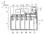
- FIG. 1 shows an external configuration of an automatic teller machine 1 according to the first embodiment.
- the automatic teller machine 1 has a substantially box-shaped housing (hereinafter also referred to as a cashier housing) 2 in which the upper corner of the front surface 2A is cut obliquely.
- a substantially box-shaped housing hereinafter also referred to as a cashier housing 2 in which the upper corner of the front surface 2A is cut obliquely.
- the direction above the automatic teller machine 1 indicated by the arrow a1 in the figure when the automatic teller machine 1 is viewed from the front surface 2A of the teller machine housing 2 is also referred to as the upward direction of the teller machine.
- the direction opposite to this is also referred to as the depositing machine downward direction, and when it is not necessary to distinguish between them, they are collectively referred to as the depositing machine vertical direction.
- the direction in front of the automatic teller machine 1 indicated by the arrow b1 in the figure when the automatic teller machine 1 is viewed facing the front surface 2A of the teller machine housing 2 is the forward direction of the teller machine.
- the direction opposite to this is also referred to as the backward direction of the deposit machine, and when it is not necessary to distinguish between these directions, they are collectively referred to as the longitudinal direction of the deposit machine.
- the left direction of the automatic teller machine 1 indicated by the arrow c1 in the figure when the automatic teller machine 1 is viewed from the front surface 2A of the teller machine housing 2 is referred to as the left direction of the teller machine.
- the direction opposite to this is also referred to as the right direction of the depositing machine, and when it is not particularly necessary to distinguish these, they are collectively referred to as the left and right direction of the depositing machine.
- the deposit machine housing 2 has, for example, a touch screen 3 capable of displaying various transaction procedure guidance images and touch operations on the surface, and a bill insertion slot for inserting and removing bills on the upper side of the front surface 2A. 4 and a plurality of operation keys 5 that can be pressed.
- the teller machine housing 2 has a card such as a cash card and a credit card inserted on the upper side of the front surface 2A, a card insertion / exhaust port 6 for discharging the card, a bankbook, and the bankbook or credit card.
- a passbook insertion outlet 7 for discharging the transaction statement is also provided.
- the teller machine housing 2 is provided with a card processing unit for performing predetermined processing relating to a card such as reading processing of an account number magnetically recorded on the card on the rear side of the card insertion / ejection slot 6 at the upper end portion inside. It has been.
- the deposit machine housing 2 is provided with a bankbook processing unit for printing transaction contents on a bankbook or transaction statement on the rear side of the bankbook insertion / exhaust port 7 at the upper end inside.
- the deposit machine housing 2 is provided with a control unit 10 and a bill deposit / withdrawal unit 11 to be described later at the lower end inside.
- the control unit 10 includes, for example, a main control unit such as a CPU (Central Processing Unit), a ROM (Read Only Memory), a RAM (Random Access Memory), and the like. Then, the main control unit reads out various programs such as basic programs and various application programs stored in advance in the ROM and expands them appropriately, thereby controlling the entire automatic teller machine 1 according to these various programs, The banknote depositing / withdrawing unit 11 and the banknote depositing / dispensing process are executed.
- a main control unit such as a CPU (Central Processing Unit), a ROM (Read Only Memory), a RAM (Random Access Memory), and the like.
- the main control unit reads out various programs such as basic programs and various application programs stored in advance in the ROM and expands them appropriately, thereby controlling the entire automatic teller machine 1 according to these various programs,
- the main control unit displays a transaction procedure guide image on the touch screen 3, and appropriately switches the transaction procedure guide image displayed on the touch screen 3 according to a touch operation on the surface of the touch screen 3 by the customer. Then, the main control unit switches a transaction procedure guide image displayed on the touch screen 3 to display a desired transaction procedure such as depositing banknotes and dispensing banknotes to the customer. invite.
- the main control unit causes a customer who follows the guidance of the transaction procedure to insert a banknote for depositing into the banknote insertion / extraction port 4.
- the main control unit causes the customer who follows the guidance of the transaction procedure to take out the banknote for withdrawal from the banknote insertion / extraction port 4.
- the main control unit discharges the card from the card insertion / extraction port 6, discharges the passbook (or transaction statement) from the passbook insertion / extraction port 7, and discharges the card and the passbook to the customer who follows the guidance of the transaction procedure. (Or transaction statement) is received.
- the main control unit can perform transactions such as deposit and withdrawal of banknotes desired by the customer in the automatic teller machine 1.
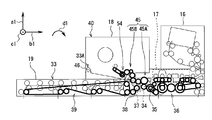
- the banknote deposit / withdrawal unit 11 includes a banknote processing block 12 and a safe block 13 that are positioned so as to overlap each other. And the banknote processing block 12 and the safe block 13 are provided with respect to the deposit machine housing
- the safe block 13 has a safe housing 20 formed in a strong box shape by a relatively thick metal plate. Further, in the safe housing 20 of the safe block 13, a single reject box 21 and a plurality of banknotes are stored in denominations in the rear direction of the deposit machine (that is, only banknotes of a specific denomination are stored). A plurality of (for example, five) banknote storages 22A to 22E are detachably mounted in order.
- a deposit / withdrawal transport unit 27 is disposed below the banknote storage case 25.
- the banknotes are transferred from the banknote storage case 25 to the lower side of the banknote storage case 25 by transport path forming components such as a transport guide, a transport roller, and a transport direction switching blade included in the deposit / withdrawal transport unit 27.
- a deposit / withdrawal transport path is formed in which the sheets are fed one by one and delivered to the transport unit 19, and banknotes are received from the transport unit 19 and stored in the banknote storage case 25.
- the temporary storage unit 18 is arranged at the center of the banknote processing block 12.
- the temporary storage unit 18 is provided with a bill temporary holding portion formed by components such as a cylindrical drum 28 and a tape reel according to the tape escrow method.
- the banknote temporary holding unit is configured to wind and hold a banknote around the peripheral side surface of the drum 28 together with the tape, and to take out the banknote by peeling the tape from the peripheral side surface of the drum 28.
- a temporary holding conveyance unit 29 is disposed below the banknote temporary holding unit.
- the banknotes taken out from between the drum 28 and the tape are transported to the lower side of the temporary banknote holding section by transport path forming parts such as transport guides and transport rollers of the temporary storage section 29.
- a temporary holding conveyance path is formed which is delivered to the unit 19 and receives bills from the conveyance unit 19 and takes in between the drum 28 and the tape.
- the transport unit 19 is connected to the banknote processing block at the lower end of the banknote processing block 12 (that is, below the depositing / withdrawing unit 16 and the temporary storage unit 18) that is substantially the center of the banknote depositing / dispensing unit 11 in the vertical direction of the depositing machine. 12 are arranged from the front end portion to the rear end portion.
- the transport unit 19 includes a transport path forming component such as a transport guide, a transport roller, and a transport direction switching blade.
- the transport unit 19 includes a substantially straight transport path that is long in the front-rear direction of the depositor, and a plurality of transport paths that branch from the transport path. , Forming.
- the transport unit 19 has a plurality of two motors arranged on the front side of the temporary holding unit 18 by a single motor located on the front side (hereinafter also referred to as a front motor).
- the transport roller is driven.
- the transport unit 19 is provided with a plurality of motors arranged on the rear side from directly below the temporary storage unit 18 by one motor located on the rear side of these two motors (hereinafter also referred to as a rear motor).
- the transport roller is driven.
- a front portion having a plurality of transport rollers driven by a front motor on the transport path formed by the transport unit 19 in front of the vicinity of the temporary storage unit 18 is also referred to as a front transport path.
- a rear portion having a plurality of conveyance rollers driven by a rear motor on the rear side of the vicinity just below 18 is also referred to as a rear conveyance path.
- the banknote processing control unit 15 selects the deposit as a desired transaction through the touch screen 3 (FIG. 1) by the customer, for example, the banknote processing control unit 15 executes the deposit process.
- the banknote processing control unit 15 opens the shutter 26 in the deposit / withdrawal unit 16 to allow the customer to insert the banknote into the banknote storage case 25.
- the banknote processing control unit 15 closes the shutter 26 in the deposit / withdrawal unit 16 and instructs the banknotes in the banknote storage case 25 when the customer instructs the banknote to be started via the touch screen 3, for example. Are taken into the transport path of the transport unit 19 one by one.
- the banknote process control part 15 discriminate
- the banknote processing control unit 15 may be a banknote that can be reused for future withdrawal processing with respect to new banknotes that are identified as normal and those that have a relatively small degree of damage. Determination is made and the final transport destination of the banknote is determined to be one of the banknote storages 22A to 22E corresponding to the denomination.
- the banknote process control part 15 judges that it is a reject banknote which is not reused for future payment processing about the banknote with a comparatively large degree of damage among the banknotes identified as normal, and the said rejection
- the final banknote transport destination is determined as the reject box 21.
- the banknote processing control unit 15 determines that banknotes that could not be identified as normal by the discrimination unit 17 are to be returned to the customer, and determines the final transport destination as the deposit / withdrawal unit 16.
- the banknote process control part 15 conveys and hold
- the banknote process control part 15 conveys to the back conveyance path via the front conveyance path in the conveyance unit 19 about the banknote (namely, banknote returned to a customer) identified as abnormal by the identification unit 17, and the said Store in the rear conveyance path. In this way, the banknote processing control unit 15 takes in and distinguishes all banknotes in the banknote storage case 25 from the deposit / withdrawal unit 16.
- the banknote process control part 15 when the banknote process control part 15 has finished discriminating all the banknotes in the banknote storage case 25, if the banknote returned to a customer is stored in a back conveyance path, the said banknote will be made to the front from a back conveyance path. It is conveyed to the deposit / withdrawal unit 16 via the conveyance path and accommodated in the bill storage case 25. Thereby, the banknote process control part 15 opens the shutter 26 in the deposit / withdrawal unit 16, returns a banknote to a customer via the banknote storage case 25, and makes the banknote storage case 25 re-insert a banknote as needed.
- the banknote processing control unit 15 has finished identifying all the banknotes in the banknote storage case 25, when banknotes to be returned to the customer are not stored in the rear conveyance path, The deposit amount is calculated based on the result of counting the denominations and the number of bills taken. And the banknote process control part 15 makes a customer select whether to continue the money_receiving
- the banknote processing control unit 15 sequentially feeds out all banknotes held from the temporary holding unit 18 and sends them to the depositing / dispensing unit 16 via the previous conveyance path. It is conveyed and stored in the banknote storage case 25. Thereby, the banknote process control part 15 opens the shutter 26 in the deposit / withdrawal unit 16, and returns a banknote to the customer via the banknote storage case 25.
- the banknote processing control unit 15 sequentially feeds out all banknotes held from the temporary holding unit 18. And the banknote process control part 15 respond
- the banknote processing control unit 15 classifies reusable banknotes among banknotes requested to be deposited by the customer, stores them in the banknote storage boxes 22A to 22E, and does not reuse them. Reject banknotes are stored in the reject box 21.
- the banknote process control part 15 can perform the deposit process of a banknote in the banknote depositing / withdrawing part 11, and can deposit the banknote as a transaction which a customer desires.
- the banknote processing control unit 15 selects withdrawal as a desired transaction via the touch screen 3 by the customer, for example, the banknote processing control unit 15 executes the withdrawal process. At this time, the banknote processing control unit 15 causes the customer to specify the withdrawal amount via the touch screen 3, and determines the denomination and the number of banknotes to be dispensed according to the designated withdrawal amount. Thereby, the banknote processing control unit 15 sequentially draws out the banknotes stored from the banknote storages 22A to 22E according to the determined denomination and number and takes them into the rear transport path of the transport unit 19.
- the banknote process control part 15 discriminate
- the banknote processing control unit 15 transports the banknote from the previous transport path to the deposit / withdrawal unit 16 and stores it in the banknote storage case 25.
- the banknote processing control part 15 will convey the said banknote from the front conveyance path to the rejection store
- the banknote process control part 15 will open the shutter 26, and will complete
- the banknote process control part 15 can perform the banknote payment process in the banknote depositing / withdrawing part 11, and can withdraw the banknote as a transaction which a customer desires.
- the transport unit 19 includes, for example, a pair of left frames (hereinafter, also referred to as a left transport frame) 33 and a right frame (hereinafter, also referred to as a right transport frame) arranged to face each other.
- the plurality of types of conveyance path forming components described above are arranged between the left conveyance frame 33 and the right conveyance frame.
- the transport unit 19 is attached to the front surface of the left transport frame 33 at a predetermined position in the center in the front-rear direction of the depositing machine with the output shaft parallel to the left-right direction of the depositing machine.
- a front motor gear 35 is fixed to the output shaft of the motor 34.
- the transport unit 19 is provided with a driving force transmission part (hereinafter also referred to as a precursor power transmission part) 36 in front of the attachment position of the front motor 34.
- a plurality of types of driving force transmission parts such as a gear, a gear pulley, a pulley, and a belt arranged in an appropriate combination with the front end portion of the outer surface of the left conveyance frame 33 form a front conveyance path with the front motor gear 35.
- the precursor power transmission unit 36 is generated by causing the front motor 34 to rotate the front motor gear 35 together with the output shaft in the first rotation direction indicated by the arrow d1 in the drawing, or in the second rotation direction opposite to this.
- a driving force that is, a rotational force
- the first rotation direction which is the rotation direction of the output shaft of the front motor 34, the front motor gear 35, and the like, is the clockwise direction when the transport unit 19 is viewed from the left side
- the second rotation direction is the transport unit 19 viewed from the left side. Counterclockwise direction.
- the transport unit 19 has a plurality of front transport paths via the precursor power transmission unit 36.
- This conveyance roller can be driven so as to convey, for example, a bill from the front side to the rear side.
- the transport unit 19 rotates a plurality of front transport paths via the precursor power transmission unit 36.
- the transport roller can be driven to transport, for example, bills from the rear side to the front side.
- the transport unit 19 is mounted on the outer surface of the left transport frame 33 on the rear side of the mounting position of the front motor 34, with the rear motor 37 described above mounted with its output shaft parallel to the left-right direction of the depositing machine.
- the rear motor gear 38 is fixed to the front.
- the transport unit 19 is also provided with a driving force transmission portion (hereinafter also referred to as a rear driving force transmission portion) 39 on the rear side of the mounting position of the rear motor 37.
- the rear driving force transmission unit 39 includes a plurality of types of driving force transmission parts arranged in appropriate combination with the rear end of the outer surface of the left conveyance frame 33, and a plurality of conveyance rollers that form a rear conveyance path with the rear motor gear 38. And connected to each other. As a result, the rear driving force transmission unit 39 generates a driving force (that is, a rotational force) generated by the rear motor 37 rotating the rear motor gear 38 together with the output shaft in the first rotational direction or the second rotational direction. It can be transmitted to a plurality of conveying rollers to be formed.
- a driving force that is, a rotational force
- the transport unit 19 is connected to the rear transport path via the rear driving force transmission unit 39.
- the plurality of transport rollers can be driven to transport, for example, bills from the rear side to the front side.
- the transport unit 19 rotates the plurality of rear transport paths via the rear driving force transmission unit 39.
- This conveyance roller can be driven so as to convey, for example, bills from the front side to the rear side.
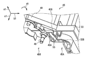
- the temporary holding unit 18 includes, for example, a pair of left frames (hereinafter also referred to as a left temporary holding frame) 40 and a right frame (hereinafter also referred to as a right temporary holding frame) arranged opposite to each other. have. Further, in the temporary storage unit 18, the component parts of the banknote temporary holding unit and the plural types of transport path forming parts of the temporary storage unit 29 are arranged between the left temporary storage frame 40 and the right temporary storage frame. .
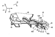
- the banknote processing block 12 is provided with a driving force transmission unit (hereinafter also referred to as an inter-unit driving force transmission unit) 45 across the transport unit 19 and the temporary storage unit 18.
- the inter-unit driving force transmission unit 45 includes a plurality of types of driving force transmission components arranged in an appropriate combination over the central portion of the outer surface of the left transport frame 33 and the lower end central portion of the outer surface of the left temporary holding frame 40.
- the motor gear 35 and a plurality of transport rollers provided in the temporary holding transport unit 29 are connected to each other. Thereby, the inter-unit driving force transmission unit 45 temporarily transfers the holding force generated by the front motor 34 rotating the front motor gear 35 together with the output shaft in the first rotation direction or the second rotation direction (that is, the rotation force). It can be transmitted to a plurality of conveying rollers provided in the section 29.
- the temporary storage unit 18 has a pair of unit support shafts 46 protruding in parallel with the left-right direction of the depositing machine, for example, at the rear lower end of the left temporary storage frame 40 and the rear lower end of the right temporary storage frame.
- the transport unit 19 has a pair of bearing portions 33 ⁇ / b> A projecting from the upper ends of the left transport frame 33 and the right transport frame at predetermined opposing positions closer to the rear than the center.
- the pair of unit support shafts 46 of the temporary storage unit 18 are rotatably inserted into the holes of the pair of bearing portions 33 ⁇ / b> A.
- the banknote processing block 12 allows the temporary storage unit 18 to move the unit support shaft 46 to the transport unit 19 so that the transport unit 19 and the temporary storage unit 18 can be maintained in a state where the banknote processing block 12 is pulled out from the deposit machine housing 2. It is attached so that it can be opened and closed by rotating in the first rotation direction and the second rotation direction around the center.
- the banknote processing block 12 opens the boundary between the front conveyance path and the rear conveyance path and the temporary retention conveyance path in a state where the temporary retention unit 18 rotates in the second rotation direction and opens upward with respect to the conveyance unit 19.
- it is attached to rotate in the first rotation direction so as to close the boundary portion between the front conveyance path and the rear conveyance path and the temporary holding conveyance path.
- the side that opens the temporary holding unit 18 (in this case, the upper side) with respect to the transport unit 19 is also referred to as the unit opening side
- the side that closes the temporary holding unit 18 with respect to the transport unit 19 (this In this case, the lower side) is also called the unit closing side.
- the inter-unit driving force transmission unit 45 includes a first transmission unit 45A provided in the transport unit 19 and a second transmission unit 45B provided in the temporary storage unit 18.
- the inter-unit driving force transmission unit 45 connects the second transmission unit 45B to the first transmission unit 45A when the temporary storage unit 18 is closed with respect to the transport unit 19. Accordingly, the inter-unit driving force transmission unit 45 transmits a driving force generated by the front motor 34 to the plurality of conveyance rollers of the temporary holding conveyance unit 29 (hereinafter, this is also referred to as an inter-unit driving force transmission route). Form). Therefore, the inter-unit driving force transmission unit 45 can convey the banknotes by rotating the plurality of conveyance rollers of the temporary holding conveyance unit 29 in the first rotation direction and the second rotation direction in accordance with the operation of the front motor 34. .
- the inter-unit driving force transmission unit 45 releases the connection between the first transmission unit 45A and the second transmission unit 45B.
- the inter-unit driving force transmission unit 45 divides the inter-unit driving force transmission path in the middle, for example, manually operates the plurality of conveyance rollers of the temporary holding conveyance unit 29 for the first rotation direction and the second rotation. It can be rotated in the direction of rotation.
- the center portion of the outer surface of the left transport frame 33 is placed at a predetermined position above the mounting position of the front motor 34, for example.
- a shaft mounting hole 33B is formed.
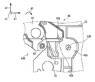
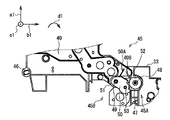
- the first transmission portion 45A is a drive gear (hereinafter, also referred to as a first joint gear) that is, for example, a spur gear for transmitting a driving force to the shaft attachment hole portion 33B of the left conveyance frame 33 to the second transmission portion 45B. 47) is attached via a first gear shaft 48 as a first shaft parallel to the left-right direction of the deposit machine.
- the first transmission portion 45A is provided in the left transport frame 33 such that the first joint gear 47 is rotatable about the first gear shaft 48 in the first rotation direction and the second rotation direction. 47 is connected to the front motor gear 35, for example, by directly meshing the teeth of each other.
- the second transmission portion 45B of the inter-unit driving force transmission portion 45 has a first gear shaft 48 when the temporary storage unit 18 is closed with respect to the transport unit 19 at the center of the lower end of the outer surface of the left temporary storage frame 40.
- a second gear shaft 49 as a second shaft is suspended in a predetermined position on the rear side in parallel with the left-right direction of the depositing machine.
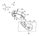
- the second transmission portion 45B has a gear support portion 50 formed in a substantially U shape by projecting a pair of support plates from both edges of the body plate.
- the gear support portion 50 has a pair of first end side shaft insertion hole portions formed at a position opposite to the first end portion of the pair of support plates, and a pair of second ends at a position opposite to the second end portion.
- a side shaft insertion hole is formed.
- the gear support 50 is, for example, a driven gear (hereinafter referred to as a spur gear) as a driving force transmission component for receiving the driving force transmitted from the first transmission portion 45A between the first ends of the pair of support plates. (This is also referred to as a second joint gear) 51 is inserted.
- the gear support portion 50 is attached to the second gear shaft 49 together with the second joint gear 51 via a pair of first end side shaft insertion hole portions and a central shaft hole of the second joint gear 51.
- the second transmission unit 45B is configured such that the second joint gear 51 and the gear support unit 50 are independent of each other around the second gear shaft 49 in the left temporary holding frame 40 in the first rotation direction and the second rotation direction. It is provided to be rotatable.
- a link gear 52 which is a spur gear, for example, is connected to the gear support portion 50 between the first ends of the pair of support plates with the second joint gear 51 meshing with and connected to each other. It is attached via a third gear shaft 53 as a third shaft inserted into the central shaft hole 52 and the pair of first end side shaft insertion holes.
- the second transmission portion 45B can rotate in the first rotation direction and the second rotation direction around the third gear shaft 53 in a state where the link gear 52 is connected to the second joint gear 51 by the gear support portion 50.
- the second gear shaft 49 is supported around the second joint gear 51 so as to be rotatable in the first rotation direction and the second rotation direction.
- the second transmission portion 45B is provided with a plurality of other types of driving force transmission components 54 (that is, other gears or other gears) shown in FIG. (Gear pulley, pulley, belt, etc.) are arranged in order.
- the second transmission unit 45 ⁇ / b> B couples these other types of driving force transmission components 54 to the second joint gear 51 and the plurality of conveyance rollers of the temporary storage unit 29.
- the second transmission unit 45B is configured such that when the temporary holding unit 18 is closed with respect to the transport unit 19 on the front side of the arrangement position of the second gear shaft 49 in the left temporary holding frame 40, the first gear shaft is left in the left transport frame 33.
- a notch 40A for fitting a front portion of the 48 arrangement position is formed.
- the gear support 50 uses the notch 40A of the left temporary holding frame 40 to connect the right end of the third gear shaft 53 to the outside of one support plate ( That is, it protrudes to the right).
- the first transmission unit 45A moves the third gear shaft 53 to connect the link gear 52 to the first joint gear 47 on the outer surface of the left transport frame 33 at the rear side of the arrangement position of the first joint gear 47.
- a guide portion 55 is provided for guiding the above.
- the guide portion 55 has a guide groove that guides the movement of the third gear shaft 53 from the obliquely upper rear side to the obliquely lower rear side of the first joint gear 47, and the shaft take-in section from the center to the groove closed end is third.
- a constant groove width substantially equal to the diameter of the gear shaft 53 is formed, and the shaft entry / exit section from the center to the groove open end is formed so as to gradually widen the groove width toward the groove open end side.
- the guide portion 55 has a guide groove with a constant groove width substantially equal to the diameter of the third gear shaft 53 in the shaft take-in section that is obliquely below the rear of the first joint gear 47.
- the groove width is formed so as to be gradually wider than the diameter of the third gear shaft 53.
- the gear support unit 50 rotates in the first rotation direction around the second gear shaft 49 due to the weight of the link gear 52 or the like.
- An abutting plate 50A for restricting rotation in the direction is provided at one end of the body plate.
- a plate-like rotation restricting portion 40B is provided at a predetermined position on the upper front side of the second gear shaft 49 (that is, on the upper side of the cutout portion 40A).
- the second transmission unit 45 ⁇ / b> B is configured such that the gear support unit 50 rotates in the first rotation direction and the link gear 52 obliquely below the second joint gear 51. Is positioned, the abutment plate 50A is abutted against the rotation restricting portion 40B to restrict the rotation of the gear support portion 50 in the first rotation direction. Therefore, even if the groove width at the groove opening end of the guide groove in the guide portion 55 is relatively narrow in the guide portion 55, the second transmission portion 45B has one end portion of the third gear shaft 53 when the temporary storage unit 18 is closed with respect to the transport unit 19. Can be accurately inserted into the guide groove from the groove open end.
- the inter-unit driving force transmission unit 45 is connected to one end of the third gear shaft 53 when the temporary storage unit 18 is closed with respect to the transport unit 19. Is inserted into the guide groove from the groove opening end on the upper rear side of the first joint gear 47. Then, the inter-unit driving force transmission unit 45 is configured such that one end of the third gear shaft 53 is obliquely below the rear of the first joint gear 47 in the guide groove in accordance with the rotation of the temporary storage unit 18 in the first rotation direction.
- the link gear 52 is meshed with the first joint gear 47 and connected to the first joint gear 47 by moving to the shaft take-in section.
- the inter-unit driving force transmission unit 45 connects the first transmission unit 45A and the second transmission unit 45B via the link gear 52. That is, when the temporary storage unit 18 is closed with respect to the transport unit 19, the inter-unit driving force transmission unit 45 is connected to the first joint gear 47 that is disposed at a fixed position in the first transmission unit 45 ⁇ / b> A.
- the second joint gear 51 arranged in a fixed position is not connected directly, but the second joint gear 51 is connected via a link gear 52 provided to be displaceable in the second transmission portion 45B. Yes.
- the second transmission portion 45B the second joint gear 51, the link gear 52, and the like are attached to the gear support portion 50 formed with relatively high formation accuracy with relatively high attachment accuracy.
- the second transmission unit 45B causes the link gear 52 and the second joint gear 51 through the gear support unit 50 so that the backlash during the interlocking rotation is about 0.1 [mm], for example. Connected.
- the distance between the axes of the unit support shaft 46 and the first gear shaft 48 and the distance between the unit support shaft 46 and the third gear shaft 53 vary within the tolerance of the design value. There is a case.
- the guide portion 55 has a virtual center line CL1 passing through the inner surface of the front plate portion, the inner surface of the rear plate portion, and the center between these inner surfaces in the shaft take-in section AR1 of the guide groove. Concentric circular arcs having different first radii r1 to third radii r3 around the one gear shaft 48 are formed.
- the guide portion 55 has a groove width that is a distance between the inner surface of the front plate portion and the inner surface of the rear plate portion (that is, two types of concentric circles centered on the first gear shaft 48) in the guide groove shaft take-in section AR1.
- the difference between the first radius r1 and the second radius r2 is selected to be approximately equal to the diameter of the third gear shaft 53 as described above.
- the guide portion 55 has a distance from the first gear shaft 48 to the virtual center line CL1 (that is, a third radius r3 of a concentric circle centered on the first gear shaft 48), so that the first joint gear 47 and the link gear 52 are connected.
- the distance between the first gear shaft 48 and the third gear shaft 53 in the case of connection is selected so that the backlash during the interlocking rotation is, for example, about 0.1 [mm].
- the second transmission unit 45 ⁇ / b> B causes the above-described variation in the inter-shaft distance to be reflected on the third gear shaft 53 in the arc-shaped shaft take-in section AR ⁇ b> 1 of the guide groove. It can be replaced with variations in the stopping position of one end. Therefore, at this time, the second transmission unit 45B determines the distance between the first gear shaft 48 and the third gear shaft 53 from the first gear shaft 48 to the virtual center line CL1 regardless of the variation in the distance between the shafts. (That is, a third radius r3 of a concentric circle centered on the first gear shaft 48) can be made substantially constant.
- the second transmission unit 45B does not provide any special mechanism for manually adjusting the backlash between the first joint gear 47 and the link gear 52, for example.
- the link gear 52 can be connected to the first joint gear 47 in a state where the backlash when they rotate in conjunction with each other is optimized by a simple operation that only closes.
- the inter-unit driving force transmission unit 45 appropriately selects the arrangement position of the unit support shaft 46, the first joint gear 47, and the second joint gear 51, for example, so as to On the other hand, it can be configured. Therefore, below, the structure of the 1st form of the driving force transmission part 45 between units and the structure of a 2nd form are demonstrated in order.
- the inter-unit driving force transmission unit 45 having the configuration of the first form is also referred to as the first inter-unit driving force transmission unit 45 as appropriate, and between the units having the configuration of the second form.
- the driving force transmission unit 45 is also referred to as a second inter-unit driving force transmission unit 45, and when it is not necessary to distinguish between them, it is also simply referred to as an inter-unit driving force transmission unit 45.
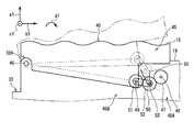
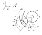
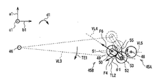
- the first inter-unit driving force transmission unit 45 is configured such that when the temporary storage unit 18 is closed with respect to the transport unit 19, the second transmission unit 45 B includes the unit support shaft 46 and the first gear shaft.
- the second gear shaft 49 and the third gear shaft 53 are arranged side by side on a first imaginary straight line VL1 that passes through a predetermined position below 48. That is, when the temporary storage unit 18 is closed with respect to the transport unit 19, the first inter-unit driving force transmission unit 45 moves the first gear shaft 48 and the second gear shaft 49 along the guide groove along the third gear shaft 53.
- the first gear shaft 48 is deviated from the second virtual straight line VL2 that passes therethrough, and the periphery of the first gear shaft 48 is turned to the unit closing side (that is, the diagonally lower rear side of the first gear shaft 48).
- the first inter-unit driving force transmission unit 45 sets the first inter-shaft distance from the first gear shaft 48 to the second gear shaft 49, and temporarily puts the first joint gear 47, the link gear 52 and the second joint gear 51 in a row.
- the distance from the first gear shaft 48 to the second gear shaft 49 in the case of connecting them in order is shorter than the distance. Accordingly, the first inter-unit driving force transmission unit 45 is arranged so that the first gear shaft 48, the third gear shaft 53, and the second gear shaft 49 are positioned at the three apexes of the triangle, respectively.
- the connected link gear 52 is further connected to the first joint gear 47.
- the first inter-unit driving force transmission unit 45 connects the first joint gear 47 of the first transmission unit 45A and the second joint gear 51 of the second transmission unit 45B via the link gear 52, thereby conveying the transport unit.
- a driving force transmission path from 19 to the temporary holding unit 18 is formed.
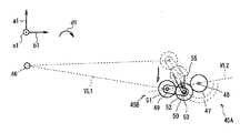
- the link gear 52 rotates in the first rotation direction. Therefore, in the first inter-unit driving force transmission unit 45, the link gear 52 is moved forward at a pressure angle ⁇ 1 of, for example, 20 degrees with respect to the tangent line TL1 of the reference pitch circle from the first joint gear 47 to the connection point of the link gear 52.
- a first pressure F1 is generated that pushes diagonally downward (that is, the unit closing side).
- the third gear shaft 53 is moved from the first joint gear 47 to the link gear 52 to the groove closing end side, which is the unit closing side, within the guide groove shaft receiving section AR1.
- a first pressure F1 is generated.
- the third gear shaft 53 is closed in the shaft take-in section AR1 of the guide groove by the first pressure F1 generated at the connection position of the link gear 52 from the first joint gear 47. Even if it moves to the side, the distance between the first gear shaft 48 and the third gear shaft 53 does not change because the shaft take-in section AR1 is arcuate as described above. Therefore, the first inter-unit driving force transmission unit 45 causes the first joint gear 47 and the link gear 52 to be connected to each other before and after the movement of the third gear shaft 53 (that is, the pitch point of each tooth and the backlash). Etc.) can be kept connected without any change.
- the second joint gear 51 rotates in the second rotation direction accordingly. Accordingly, in the first inter-unit driving force transmission unit 45, the second joint gear 51 is connected to the connection point of the second joint gear 51 from the link gear 52 at a pressure angle ⁇ 1 of, for example, 20 degrees with respect to the tangent line TL2 of the reference pitch circle. A second pressure F2 is also generated that pushes the front diagonally upward (that is, the unit opening side).
- the second joint gear 51 is connected to the link gear 52 via the gear support unit 50.
- the gear support unit 50 For this reason, in the first inter-unit driving force transmission unit 45, when the second joint gear 51 tries to move obliquely upward in the forward direction by the second pressure F2, a link is generated that causes the first pressure F1 to be pushed obliquely downward in the forward direction.
- the third gear shaft 53 of the gear 52 is pressed against the inner surface of the rear plate portion of the guide portion 55.
- the guide unit 55 and the third gear shaft 53 of the link gear 52 are It functions as a restricting part that restricts the movement, and the position of the second joint gear 51 does not change.
- the link gear 52 is connected to the first joint gear 47. It can be urged to move to the unit closing side. Accordingly, the first inter-unit driving force transmission unit 45 opens the temporary storage unit 18 with respect to the transport unit 19 even when the first joint gear 47 rotates in the second rotation direction in accordance with the operation of the front motor 34. As a result, the driving force transmission path extending from the transport unit 19 to the temporary storage unit 18 can be kept formed and unintentional splitting can be avoided.
- the first inter-unit driving force transmission unit 45 transmits the rotation of the first joint gear 47 in the second rotation direction to the second joint gear 51 via the link gear 52, and the second joint gear 51 also It can be rotated in the second rotation direction. Further, the first inter-unit driving force transmission unit 45 rotates the second joint gear 51 in the second rotation direction, and sequentially passes through a plurality of other types of driving force transmission components 54 to sequentially move the plurality of temporary holding conveyance units 29. It can be transmitted to the transport roller. Thereby, the 1st unit driving force transmission part 45 can rotate the some conveyance roller of the conveyance part 29 for temporary storage so that a banknote may be conveyed in a predetermined
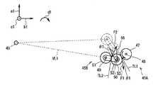
- the third gear shaft 53 is moved from the first joint gear 47 to the link gear 52 to the groove opening end side that is the unit opening side in the shaft groove section AR1 of the guide groove.
- a third pressure F3 is generated.
- the second joint gear 51 rotates in the first rotation direction according to the rotation of the link gear 52 in the second rotation direction. Accordingly, in the first inter-unit driving force transmission unit 45, the second joint gear 51 is connected to the connection point of the second joint gear 51 from the link gear 52 at a pressure angle ⁇ 1 of, for example, 20 degrees with respect to the tangent line TL2 of the reference pitch circle.
- a fourth pressure F4 is also generated that pushes backward and obliquely downward (that is, the unit closing side).
- the link gear 52 is pushed while pushing the second joint gear 51 toward the unit closing side.
- the link gear 52 is urged so as to move from the connection position with the first joint gear 47 to the unit opening side.
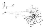
- the first gear shaft 48 and the second gear shaft 49 are respectively positioned at two vertices on the triangular unit opening side protruding to the unit closing side, and the third gear shaft
- the first joint gear 47 and the second joint gear 51 are connected via a link gear 52 by positioning 53 at one vertex on the unit closing side of the triangle. Therefore, in the first inter-unit driving force transmission unit 45, the first inter-shaft distance D1 from the first gear shaft 48 to the second gear shaft 49 is the second shaft from the first gear shaft 48 to the third gear shaft 53. It is longer than the inter-distance distance D2 or the third inter-axis distance D3 from the second gear shaft 49 to the third gear shaft 53, and shorter than the distance obtained by adding the second inter-axis distance D2 and the third inter-axis distance D3.
- the gap between the first joint gear 47 and the second joint gear 51 is narrower than the gear diameter of the link gear 52. That is, the first inter-unit driving force transmission unit 45 is configured so that the link gear 52 opens the temporary storage unit 18 with respect to the transport unit 19 when the temporary storage unit 18 is closed with respect to the transport unit 19. If the gap between the first joint gear 47 and the second joint gear 51 is not widened, the first joint gear 47 and the first joint gear 47 are arranged so that they cannot move from the connection position to the unit opening side.
- the fifth pressure F5 that pushes the second joint gear 51 to the rear side acts from the link gear 52 to the second joint gear 51.
- the second joint gear 51 is fixedly disposed on the outer surface of the left temporary holding frame 40, and the unit support shaft 46 is also positioned on the left temporary holding frame 40. It is fixedly arranged.
- the second gear shaft 49 and the third gear shaft 53 are positioned on the first virtual straight line VL1 passing through the unit support shaft 46 as described above.
- the fifth pressure F5 is applied from the link gear 52 to the second joint gear 51, and the second joint gear 51 is placed on the rear side on the first virtual straight line VL1. It acts to push in the direction of 46. That is, in the first inter-unit driving force transmission unit 45, the fifth pressure F5 is applied from the link gear 52 to the second joint gear 51, and the second joint gear 51 serves as a unit support that serves as the rotation center of the temporary storage unit 18 with respect to the transport unit 19. It acts to push in the direction of the shaft 46.
- the unit support shaft 46 can receive the fifth pressure F5 by functioning as a receiving portion that receives the fifth pressure F5.
- the first unit driving force transmission unit 45 does not change the position even if the second joint gear 51 is pushed to the rear side.
- the link gear 52 is connected to the first joint gear 47. Moving from the connecting position to the unit opening side can be avoided.
- the first inter-unit driving force transmission unit 45 transmits the rotation of the first joint gear 47 in the first rotation direction to the second joint gear 51 via the link gear 52, and the second joint gear 51 also It can be rotated in the first rotation direction. Further, the first inter-unit driving force transmission unit 45 rotates the second joint gear 51 in the first rotation direction, and sequentially passes through a plurality of other types of driving force transmission components 54 to sequentially move the plurality of temporary holding conveyance units 29. It can be transmitted to the transport roller. As a result, the first inter-unit driving force transmission unit 45 causes the plurality of conveyance rollers of the temporary holding conveyance unit 29 to transfer bills in the conveyance direction opposite to the case where the first joint gear 47 rotates in the second rotation direction. It can be rotated to carry.
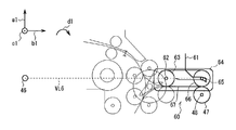
- the straight line VL4 is configured to intersect at an acute intersection angle that is as close to a parallel relationship as possible. Therefore, when the temporary storage unit 18 is closed with respect to the transport unit 19, the second inter-unit driving force transmission unit 45 moves the first gear shaft 48 and the second gear shaft 49 along the guide groove along the third gear shaft 53.
- the first gear shaft 48 is deviated from the fifth imaginary straight line VL5 that passes therethrough and turns around the first gear shaft 48 toward the unit closing side (that is, the diagonally lower rear side of the first gear shaft 48).
- the temporary storage unit 18 provided with the second transmission unit 45B which is a part of the second inter-unit driving force transmission unit 45, is provided with a temporary storage unit 29 and a bill temporary storage unit, thereby providing a certain weight.
- a temporary storage unit 29 and a bill temporary storage unit thereby providing a certain weight.
- the second inter-unit driving force transmission unit 45 As a result, in the second inter-unit driving force transmission unit 45, as in the case of the first inter-unit driving force transmission unit 45 described above, the first gear shaft 48, the third gear shaft 53, and the second gear shaft 49 are made triangular.
- the link gear 52 connected to the second joint gear 51 is further connected to the first joint gear 47 so as to be positioned at the three apexes.
- the second inter-unit driving force transmission unit 45 connects the first joint gear 47 of the first transmission unit 45A and the second joint gear 51 of the second transmission unit 45B via the link gear 52, A driving force transmission path from the transport unit 19 to the temporary storage unit 18 is formed.
- the second inter-unit driving force transmission unit 45 uses the unit closing torque TE1 to transmit the driving force while the temporary storage unit 18 is closed.
- the degree of freedom in design can be increased, such as narrowing the rotation range of the link gear 52 relative to the periphery of the second joint gear 51.
- the transport unit 19 and the temporary storage unit 18 are also provided with the above-described first inter-unit driving force transmission unit 45 at the height position of the unit support shaft 46 with respect to the lower surface of the transport unit 19, for example.
- the degree of freedom in design can be increased so as to be lower than the above.
- the second inter-unit driving force transmission unit 45 when the first joint gear 47 rotates in the second rotation direction according to the operation of the front motor 34, the same as in the case of the first inter-unit driving force transmission unit 45 described above.
- the link gear 52 can be urged to move to the unit closing side while being connected to the first joint gear 47. Accordingly, the second inter-unit driving force transmission unit 45 opens the temporary storage unit 18 with respect to the transport unit 19 even when the first joint gear 47 rotates in the second rotation direction in accordance with the operation of the front motor 34.
- the driving force transmission path extending from the transport unit 19 to the temporary storage unit 18 can be kept formed and unintentional splitting can be avoided.
- the second inter-unit driving force transmission unit 45 also rotates the first joint gear 47 in the second rotation direction by using the link gear 52 and the second joint gear 51 and other types of driving force transmission components 54.
- the data can be transmitted to a plurality of conveyance rollers of the temporary holding conveyance unit 29 sequentially.
- the second inter-unit driving force transmission unit 45 can rotate the plurality of conveyance rollers of the temporary holding conveyance unit 29 so as to convey the banknotes in a predetermined conveyance direction.
- the link gear 52 when the first joint gear 47 rotates in the first rotation direction in accordance with the operation of the front motor 34, the link gear 52 sequentially changes in accordance with the rotation.
- the second joint gear 51 rotates in the first rotation direction.
- the link gear 52 is used as a reference from the first joint gear 47 to the connection point of the link gear 52.
- a third pressure is generated that pushes backward and obliquely upward (that is, the unit opening side) with a pressure angle of, for example, 20 degrees with respect to the tangent to the pitch circle.
- the second joint gear 51 is connected to the connection point of the second joint gear 51 from the link gear 52 at this time, for example, a pressure of 20 degrees with respect to the tangent TL2 of the reference pitch circle.
- a fourth pressure F4 is also generated that pushes backward and obliquely downward (that is, the unit closing side) at the angle ⁇ 1. Therefore, in the second inter-unit driving force transmission unit 45, when the first joint gear 47 rotates in the first rotation direction in accordance with the operation of the front motor 34, the link gear while pushing the second joint gear 51 toward the unit closing side.
- the link gear 52 is urged so as to move from the connection position with the first joint gear 47 to the unit opening side by pushing the button 52 toward the unit opening side.
- the first gear shaft 48 and the second gear shaft 49 are respectively positioned at two vertices on the triangular unit opening side protruding to the unit closing side,
- the gear shaft 53 is positioned at one vertex on the unit closing side of the triangle, and the first joint gear 47 and the second joint gear 51 are connected via the link gear 52. Therefore, in the second inter-unit driving force transmission unit 45, the first inter-axis distance is longer than the second inter-axis distance and the third inter-axis distance, but is shorter than the sum of these distances. As a result, the first joint
- the gap between the gear 47 and the second joint gear 51 is narrower than the gear diameter of the link gear 52.
- the link gear 52 opens the temporary storage unit 18 with respect to the transport unit 19.
- the joint gear 47 and the second joint gear 51 are arranged so that they cannot move from the connection position with the first joint gear 47 to the unit opening side.
- the sixth pressure F6 that pushes the second joint gear 51 rearward from the link gear 52 to the second joint gear 51 with the urging to the link gear 52.
- the unit support shaft 46 is a fourth imaginary straight line passing through the second gear shaft 49 and the third gear shaft 53.
- the fourth virtual straight line VL4 intersects with the third virtual straight line VL3 and extends obliquely upward on the rear side of the unit opening side with respect to the third virtual straight line VL3.
- the sixth pressure F6 is applied from the link gear 52 to the second joint gear 51, and the second joint gear 51 is disposed on the fourth virtual straight line VL4. It works to push upward.
- the temporary storage unit 18 generates a unit closing torque TE1 that tends to rotate in the first rotation direction so as to maintain a closed state with respect to the transport unit 19 due to its own weight.
- the temporary holding unit 18 Even if the weight of the unit is relatively light and the unit closing torque TE1 is relatively small, the resultant force of the unit closing torque TE1, the fourth pressure F4, and the sixth pressure F6 causes the temporary storage unit 18 to be pushed toward the unit closing side. Force (that is, a force for rotating the temporary storage unit 18 in the first rotation direction).
- the second inter-unit driving force transmission unit 45 even if the sixth pressure F6 is applied from the link gear 52 to the second joint gear 51 so as to push upward from the position where the unit support shaft 46 is disposed, the own weight is compared.
- the light temporary holding unit 18 can function as a receiving unit that receives pressure, and the temporary holding unit 18 can receive the sixth pressure F6.
- the position of the second joint gear 51 is not changed even if the second joint gear 51 is pushed upward.
- the link gear 52 is connected to the first joint gear 47. Moving from the position to the unit opening side can also be avoided.
- the link gear 52 is kept in the connection position with the first joint gear 47, and the first joint gear 47 and the link gear 52 are in their connected state (that is, the mutual teeth).
- the connection can be continued without changing the pitch point, backlash, etc.).
- the second inter-unit driving force transmission unit 45 opens the temporary storage unit 18 with respect to the transport unit 19 even when the first joint gear 47 rotates in the first rotation direction in accordance with the operation of the front motor 34.
- the driving force transmission path extending from the transport unit 19 to the temporary storage unit 18 can be kept formed and unintentional splitting can be avoided.
- the second inter-unit driving force transmission unit 45 transmits the rotation of the first joint gear 47 in the first rotation direction to the second joint gear 51 via the link gear 52, and the second joint gear 51 also It can be rotated in the first rotation direction. Further, the second inter-unit driving force transmission unit 45 rotates the second joint gear 51 in the first rotation direction, and sequentially passes through a plurality of other types of driving force transmission components 54 to sequentially move the plurality of temporary holding conveyance units 29. It can be transmitted to the transport roller.
- the second inter-unit driving force transmission unit 45 is different in configuration from the first inter-unit driving force transmission unit 45, but the first joint gear 47 rotates in one rotation direction according to the operation of the front motor 34.
- the plurality of transport rollers of the temporary holding transport unit 29 can be rotated so as to transport bills in the transport direction opposite to that in the case where the first joint gear 47 rotates in the second rotation direction.
- FIGS. 3 and 8 illustrate the configuration of the first inter-unit driving force transmission unit 45.
- FIGS. 5A and 5B, and FIGS. 7A and 7B show the configuration of the second inter-unit driving force transmission unit 45.
- 6 and 9 show a configuration common to the first inter-unit driving force transmission unit 45 and the second inter-unit driving force transmission unit 45.
- the automatic teller machine 1 is provided with the temporary storage unit 18 with respect to the transport unit 19 so as to be openable and closable via the unit support shaft 46.
- the driving force generated by the front motor 34 provided in the transport unit 19 is transmitted to the plurality of transport rollers provided in the temporary storage unit 18 across the transport unit 19 and the temporary storage unit 18.
- An inter-unit driving force transmission unit 45 is provided.
- the second joint gear 51 and the gear support portion 50 are mutually connected to the temporary storage unit 18 as the second transmission portion 45 ⁇ / b> B of the inter-unit driving force transmission portion 45 via the second gear shaft 49.
- the gear support portion 50 is provided so as to be rotatable via a third gear shaft 53 in a state where the link gear 52 is connected to the second joint gear 51.
- the first joint gear 47 connected to the front motor gear 35 of the front motor 34 is used as the first transmission unit 45 ⁇ / b> A of the inter-unit driving force transmission unit 45 in the transport unit 19.
- a guide portion 55 that guides the link gear 52 to be connected to the first joint gear 47 by a guide groove that moves one end portion of the third gear shaft 53.
- the automatic teller machine 1 when the temporary storage unit 18 is closed with respect to the transport unit 19, the automatic teller machine 1 is configured so that the second gear gear 52 is connected to the second joint gear 51 in the inter-unit driving force transmission unit 45. While being rotated with respect to the periphery of the joint gear 51, the guide portion 55 guided to the connection position with the first joint gear 47 and connected to the first joint gear 47. Thus, the automatic teller machine 1 connects the second joint gear 51 to the first joint gear 47 via the link gear 52 in the inter-unit driving force transmission unit 45 (that is, the second transmission to the first transmission unit 45A).
- the driving force transmission path for transmitting the driving force generated by the front motor 34 from the transport unit 19 to the temporary storage unit 18 is formed.
- the automatic teller machine 1 when the first joint gear 47 rotates in the second rotation direction in accordance with the operation of the front motor 34, the automatic teller machine 1 connects the link gear 52 from the first joint gear 47. Due to the pressure generated in the direction of the pressure angle, the link gear 52 can be urged to move to the unit closing side while being connected to the first joint gear 47 by the guide portion 55. Therefore, the automatic teller machine 1 does not cause the transport unit 19 to open the temporary storage unit 18 and unintentionally divides the driving force transmission path from the transport unit 19 to the temporary storage unit 18. You can avoid that.
- the automatic teller machine 1 moves in the direction of the pressure angle from the first joint gear 47 to the connection point of the link gear 52.
- the link gear 52 is urged to move to the unit closing side by the generated pressure
- the pressure generated to move the link gear 52 from the link gear 52 to the second joint gear 51 by the urging is applied to the tip of the pressure. It can be received by the receiving portion (that is, the unit support shaft 46 or the temporary storage unit 18).
- the automatic teller machine 1 can avoid the link gear 52 from moving from the connection position with the first joint gear 47 to the unit opening side without changing the position of the second joint gear 51, As a result, it is possible to avoid unintentionally dividing the driving force transmission path extending from the transport unit 19 to the temporary storage unit 18 without causing the transport unit 19 to open the temporary storage unit 18. it can.
- the automatic teller machine 1 allows the first joint gear 47 to move according to the operation of the front motor 34 without providing a lock mechanism for locking the temporary storage unit 18 in the closed state with respect to the transport unit 19.
- the first joint gear 47 and the second joint gear 51 remain connected via the link gear 52 regardless of whether the rotation is in the first rotation direction or the second rotation direction, and the driving force transmission path is easily maintained. can do.
- the automatic teller machine 1 when the temporary storage unit 18 is closed with respect to the transport unit 19, the third gear shaft 53 is positioned closer to the unit closing side than the virtual straight line passing through the first gear shaft 48 and the second gear shaft 49. Thus, the link gear 52 is connected to the first joint gear 47.
- the automatic teller machine 1 receives the pressure generated from the link gear 52 in the second joint gear 51 at the receiving portion. Thus, the position of the second joint gear 51 is prevented from changing.
- the automatic teller machine 1 keeps the link gear 52 at the connection position with the first joint gear 47, and The one joint gear 47 and the link gear 52 can continue to be connected without changing their connection state, and the link gear 52 can be connected to the second gear according to the rotation of the first joint gear 47 in the first rotation direction. It can be accurately rotated in the direction of rotation.
- the automatic teller machine 1 when the temporary storage unit 18 is closed with respect to the transport unit 19, the second gear shaft 49 and the third gear shaft 53 are positioned on a virtual straight line passing through the unit support shaft 46, The link gear 52 is connected to the one joint gear 47. Therefore, when the first joint gear 47 rotates in the first rotation direction in accordance with the operation of the front motor 34, the automatic teller machine 1 moves from the link gear 52 to the second joint gear 51 along the virtual straight line. A pressure can be created that moves toward 46.
- the automatic teller machine 1 causes the unit support shaft 46 to function as a receiving portion without providing a receiving portion, and the pressure generated from the link gear 52 to the second joint gear 51 by the unit support shaft 46. Can be prevented from changing the position of the second joint gear 51. And since the automatic teller machine 1 does not act so that the temporary storage unit 18 may be opened with respect to the conveyance unit 19 by the said structure, it can also form the said temporary storage unit 18 so that self weight may become comparatively light. .
- the temporary holding unit 18 is formed so as to generate the unit closing torque TE1 by its own weight.
- the automatic teller machine 1 positions the second gear shaft 49 and the third gear shaft 53 on the virtual straight line passing through the unit support shaft 46. Even if the link gear 52 is not connected to the one joint gear 47, the temporary holding unit 18 is caused to function as a receiving portion, and the temporary holding unit 18 generates the second joint gear 51 from the link gear 52. It is possible to avoid a change in the position of the second joint gear 51 by receiving the pressure. Accordingly, the automatic teller machine 1 can increase the degree of freedom in designing the inter-unit driving force transmission unit 45, the temporary storage unit 18, and the transport unit 19.
- the guide groove 55 is gradually widened toward the groove opening end side in the shaft opening / closing section on the groove opening end side by the guide portion 55, and the shaft taking-in section on the groove closing end side is in the third section.
- a constant groove width substantially equal to the diameter of the gear shaft 53 is formed in an arc shape centering on the first gear shaft 48. Accordingly, in the automatic teller machine 1, the distance between the unit support shaft 46 and the first gear shaft 48 and the distance between the unit support shaft 46 and the third gear shaft 53 are within the tolerances of the design values in the second transmission unit 45B.
- the automatic teller machine 1 sets the distance between the first gear shaft 48 and the third gear shaft 53 substantially constant to the first joint gear 47 regardless of variations in the distance between the axes of the second transmission portion 45B.
- a link gear 52 can be connected.
- the first unit gear 47 and the guide unit 55 are provided in the transport unit 19 in the inter-unit driving force transmission unit 45, and the second joint gear 51 and the second joint are provided in the temporary storage unit 18.
- the case where the link gear 52 connected to the gear 51 via the gear support 50 is provided has been described.
- the present disclosure is not limited to this.
- the first joint gear 47 is provided on the transport unit 19 via the first gear shaft 48 in the inter-unit driving force transmission unit 60.
- a guide portion 61 is provided from the rear oblique upper side to the front oblique upper side of the joint gear 47.
- the guide portion 61 guides the guide groove, and the shaft entry / exit section from the center that is almost directly above the first joint gear 47 to the groove opening end on the rear obliquely upper side gradually widens the groove width.
- the shaft take-in section up to the obliquely upper groove closed end is formed in an arc shape centered on the first gear shaft 48 with a constant groove width.
- a pulley 63 as a driving force transmission component and a gear support 64 are arranged independently of each other in the first rotation direction and the second rotation centering on the pulley shaft 62 as the second shaft.
- a link gear 66 which is a gear pulley, can be rotated in the first rotation direction and the second rotation direction around the fourth gear shaft 65 as the third shaft.
- the link gear 66 and the pulley 63 are connected via an endless belt 67.
- the first joint gear 47 when the first joint gear 47 rotates in the first rotation direction according to the operation of the front motor 34, the first joint gear 47 changes to the link gear 66 within the shaft groove section of the guide groove. A pressure is generated to move the four-gear shaft 65 toward the groove closing end which is the unit closing side. That is, in the present disclosure, the link gear 66 connected to the pulley 63 via the belt 67 can be urged to move to the unit closing side while being connected to the first joint gear 47. As a result, the present disclosure does not cause the transport unit 19 to open the temporary storage unit 18 and unintentionally divides the driving force transmission path from the transport unit 19 to the temporary storage unit 18. It can be avoided.
- the fourth joint gear 47 moves from the first joint gear 47 to the link gear 66 within the guide groove shaft take-in section.
- a pressure is generated to move the gear shaft 65 toward the groove closed end.
- pressure is generated from the link gear 66 to the pulley 63 so as to push the pulley 63 rearward.
- the pulley shaft 62 and the fourth gear shaft 65 are located on the sixth virtual straight line VL6 passing through the unit support shaft 46, the rear side on the sixth virtual straight line VL6 from the link gear 66 to the pulley 63 is provided.
- the pressure can be generated so as to push in the direction of the unit support shaft 46, and the pressure can be received by the unit support shaft 46. Thereby, this indication can avoid moving link gear 66 from the connection position with the 1st joint gear 47 to the unit opening side, without changing the position of pulley 63, and, as a result, conveyance unit 19
- the drive force transmission path from the transport unit 19 to the temporary storage unit 18 can be prevented from being unintentionally divided without acting to open the temporary storage unit 18.
- the same effect as that of the above-described embodiment can be obtained even by the above configuration.
- the temporary storage unit 18 when the temporary storage unit 18 can generate a predetermined unit closing torque by its own weight, when the temporary storage unit 18 is closed with respect to the transport unit 19, the pulley shaft 62 and the Even if the link gear 66 is connected to the first joint gear 47 so that the virtual straight line passing through the four-gear shaft 65 is inclined, the same effect as in the case of the above-described embodiment can be obtained.
- the transport unit 19 is provided with the first transmission unit 45A of the inter-unit driving force transmission unit 45 together with the front motor 34, and the second transmission of the inter-unit driving force transmission unit 45 is provided to the temporary storage unit 18.
- the part 45B is provided has been described.
- the temporary holding unit 18 is provided with the first transmission unit 45A of the inter-unit driving force transmission unit 45 together with the front motor 34, and the second unit of the inter-unit driving force transmission unit 45 is provided in the transport unit 19.
- a transmission unit 45B may be provided.
- the above configuration may be applied to the various configurations described in the other embodiment 2 or the other embodiment 3.
- the present disclosure is not limited to this, and the transport unit 19 and the deposit / withdrawal unit 16 that can be opened and closed, the transport unit 19 and the discrimination unit 17 that can be opened and closed, the first unit and the second unit that can be opened and closed by the front opening, and the rear opening
- the first unit and the second unit that can be opened and closed in various configurations, such as the first unit and the second unit that can be opened and closed by the first, the first unit and the second unit that can be opened and closed by the lower opening, are widely applied. be able to.
- the gear support portion provided in the second unit so as to be rotatable about the second axis and independently of the driving force transmission portion is used as the gear support portion described above with reference to FIGS.
- the case where the U-shaped gear support 50 is applied has been described.
- the present disclosure is not limited to this, and various other types of gear support portions such as a substantially strip-shaped gear support portion and a substantially L-shaped gear support portion can be widely applied.
- Embodiment 12 a guide provided in the first unit and guiding the link gear to be connected to the drive gear by the guide groove that moves the third shaft when the first unit and the second unit are closed.
- the guide parts 55 and 61 described above with reference to FIGS. 1 to 14 are applied has been described.
- the present disclosure is not limited to this, and various other configurations of the guide portion can be widely applied, such as a guide portion in which the shaft receiving section of the guide groove is formed in a bow shape with a constant groove width.
- the unit support shaft 46 provided in the temporary storage unit 18 described above with reference to FIGS. 1 to 14 is applied as the unit support shaft that supports the first unit and the second unit so as to be openable and closable. Said about the case.
- the present disclosure is not limited to this, and a unit support shaft provided in the transport unit 19 can be applied.
- the present disclosure relates to an automatic teller machine, an automatic teller machine, a change machine, a ticket vending machine, a checkout machine, a copier, a copier, a postcard handling device, and a medium processing device, and a driving force transmission device provided in the medium processing device.
Landscapes
- Engineering & Computer Science (AREA)
- General Engineering & Computer Science (AREA)
- Mechanical Engineering (AREA)
- Delivering By Means Of Belts And Rollers (AREA)
- Gear Transmission (AREA)
Abstract
開閉可能な第1ユニット及び第2ユニットと、前記第1ユニットに第1軸を中心にして回転可能に設けられた駆動ギアと、前記第2ユニットに第2軸を中心にして回転可能に設けられた駆動力伝達部品と、前記第2ユニットに前記第2軸を中心にして、前記駆動力伝達部とは独立して回転可能に設けられたギア支持部と、前記ギア支持部に、前記駆動力伝達部品と接続した状態で第3軸を中心にして回転可能に設けられたリンクギアと、前記第1ユニットに設けられ、当該第1ユニット及び前記第2ユニットが閉じる際、前記第3軸を移動させるガイド溝により前記リンクギアを前記駆動ギアに接続するようにガイドするガイド部と、を備える、駆動力伝達装置。前記第1ユニット及び前記第2ユニットを閉じた場合、前記駆動ギア及び前記駆動力伝達部品を、前記リンクギアを介して連結して駆動力伝達経路を形成する。
Description
本開示は駆動力伝達装置及び媒体処理装置に関し、詳細には、例えば、媒体としての紙幣を搬送して入金処理や出金処理する現金自動預払機(ATM:Automatic Teller Machine)に適用される駆動力伝達装置及び媒体処理装置に関する。
関連技術の媒体処理装置では、下部ユニットに、複数の搬送ローラが設けられた下部ガイド板が開閉可能に取り付けられ、複数の搬送ローラが設けられた上部ガイド板を備える上部ユニットも開閉可能に取り付けられている。また、媒体処理装置では、上部ユニットにロックレバーが設けられ、下部ユニットにロックポストが設けられている。
よって、媒体処理装置では、下部ユニットに対して、上部ユニットと共に下部ガイド板が閉じられると、ロックレバーをロックポストに係合させて当該下部ユニットに上部ユニットを閉じた状態にロックすることで、下部ガイド板及び上部ガイド板の間に媒体搬送路を形成する。これにより媒体処理装置は、下部ガイド板及び上部ガイド板の間で媒体を、上下の対応する搬送ローラ同士によって挟み込むようにして搬送する(例えば、特開平11-322126公報参照)。
ところで、関連技術の媒体処理装置では、例えば、下部ユニットにモータが設けられ、当該モータの出力軸に連結された駆動ギアが位置を固定して設けられている。また、媒体処理装置は、例えば、下部ガイド板に、複数の搬送ローラのシャフトに連結された従動ギアが位置を固定して設けられている。そして、媒体処理装置は、下部ユニットに対して、上部ユニットと共に下部ガイド板が閉じられると、駆動ギアに従動ギアを、互いの歯を噛み合わせて、接続する。これにより、媒体処理装置は、モータが発生させる駆動力を、駆動ギア及び従動ギアを順次介して下部ガイド板の複数の搬送ローラに伝達する駆動力伝達経路を形成し、モータの動作に応じて複数の搬送ローラを回転可能にしている。
ところが一般的に、駆動ギアに接続した従動ギアには、当該駆動ギアが回転した場合、その駆動ギアから圧力角の方向へ押して離隔させるような圧力が生じる。そして、関連技術の媒体処理装置のように、開閉可能な下部ユニット及び下部ガイド板に設けた駆動ギア及び従動ギアを接続して駆動力伝達経路を形成すると、駆動ギアの回転に応じて従動ギアに生じた圧力が、下部ユニットに対して、下部ユニットを開くように作用して駆動ギアから従動ギアを離隔させ、駆動力伝達経路が意図せずに分断することになる。このため、媒体処理装置では、上部ユニット及び下部ユニットにロックレバー及びロックポストを設け、これらロックレバー及びロックポストを介して、下部ユニットに上部ユニットと共に下部ガイド板を閉じた状態にロックすることで、駆動ギアの回転に応じて従動ギアに離隔させるような圧力が生じても、当該駆動ギアに従動ギアを接続し続けるようにしており、駆動力伝達経路を容易には維持し難いという問題があった。
本開示は以上の点を考慮して、駆動力伝達経路を容易に維持し得る駆動力伝達装置及び媒体処理装置を提案する。
上記課題を解決するため、本開示においては、開閉可能な第1ユニット及び第2ユニットと、第1ユニットに第1軸を中心にして回転可能に設けられた駆動ギアと、第2ユニットに第2軸を中心にして回転可能に設けられた駆動力伝達部品と、第2ユニットに第2軸を中心にして、駆動力伝達部品とは独立して回転可能に設けられたギア支持部と、ギア支持部に、駆動力伝達部品と接続した状態で第3軸を中心にして回転可能に設けられたリンクギアと、第1ユニットに設けられ、当該第1ユニット及び第2ユニットが閉じる際、第3軸を移動させるガイド溝によりリンクギアを駆動ギアに接続するようにガイドするガイド部と、を設け、第1ユニット及び第2ユニットを閉じた場合、駆動ギア及び駆動力伝達部品を、リンクギアを介して連結して駆動力伝達経路を形成する。
従って、本開示では、駆動ギアが一方に回転した場合、リンクギアを駆動ギアと接続したままユニット閉側へ付勢して、第1ユニット及び第2ユニットを閉じたままにし得る。また、駆動ギアが他方に回転した場合、リンクギアをユニット閉側へ付勢するが、当該付勢によりリンクギアから駆動力伝達部品に移動させるように生じる圧力を、当該圧力の向いた先に位置する受止部で受止めて駆動力伝達部品及びリンクギアの位置が変化することを回避して、第1ユニット及び第2ユニットを閉じたままにすることができる。その結果、本開示では、第1ユニット及び第2ユニットを閉じた状態にロックするためのロック機構を特に設けることなく、駆動ギアが一方及び他方の何れに回転した場合でも、駆動ギア及び駆動力伝達部品を、リンクギアを介して連結し続けて、駆動力伝達経路が意図せずに分断することを回避することができる。
本開示によれば、開閉可能な第1ユニット及び第2ユニットと、第1ユニットに第1軸を中心にして回転可能に設けられた駆動ギアと、第2ユニットに第2軸を中心にして回転可能に設けられた駆動力伝達部品と、第2ユニットに第2軸を中心にして、駆動力伝達部とは独立して回転可能に設けられたギア支持部と、ギア支持部に、駆動力伝達部品と接続した状態で第3軸を中心にして回転可能に設けられたリンクギアと、第1ユニットに設けられ、当該第1ユニット及び第2ユニットが閉じる際、第3軸を移動させるガイド溝によりリンクギアを駆動ギアに接続するようにガイドするガイド部と、を設け、第1ユニット及び第2ユニットを閉じた場合、駆動ギア及び駆動力伝達部品を、リンクギアを介して連結して駆動力伝達経路を形成する。これにより、第1ユニット及び第2ユニットを閉じた状態にロックするためのロック機構を特に設けることなく、駆動ギアが一方及び他方の何れに回転した場合でも、駆動ギア及び駆動力伝達部品を、リンクギアを介して連結し続けて、駆動力伝達経路が意図せずに分断することを回避することができる。したがって、駆動力伝達経路を容易に維持し得る駆動力伝達装置及び媒体処理装置を実現することができる。
以下図面を用いて、実施形態について説明する。なお、説明は以下の順序で行う。
(1)実施形態
(2)他の実施形態
(1)実施形態
(2)他の実施形態
(1)実施形態
(1-1)現金自動預払機の外観構成
図1は、第1実施形態による現金自動預払機1の外観構成を示す。現金自動預払機1は、前面2Aの上側の隅部が斜めに切り欠かれたような略箱型の筐体(以下、これを預払機筐体とも呼ぶ)2を有している。以下の説明では、現金自動預払機1を預払機筐体2の前面2Aと対峙して見た場合の図中に矢印a1で示す現金自動預払機1の上の方向を預払機上方向とも呼び、これとは逆の方向を預払機下方向とも呼び、これらを特に区別する必要がない場合は、まとめて預払機上下方向とも呼ぶ。
(1-1)現金自動預払機の外観構成
図1は、第1実施形態による現金自動預払機1の外観構成を示す。現金自動預払機1は、前面2Aの上側の隅部が斜めに切り欠かれたような略箱型の筐体(以下、これを預払機筐体とも呼ぶ)2を有している。以下の説明では、現金自動預払機1を預払機筐体2の前面2Aと対峙して見た場合の図中に矢印a1で示す現金自動預払機1の上の方向を預払機上方向とも呼び、これとは逆の方向を預払機下方向とも呼び、これらを特に区別する必要がない場合は、まとめて預払機上下方向とも呼ぶ。
また、以下の説明では、現金自動預払機1を預払機筐体2の前面2Aと対峙して見た場合の図中に矢印b1で示す現金自動預払機1の前の方向を預払機前方向とも呼び、これとは逆の方向を預払機後方向とも呼び、これらを特に区別する必要がない場合は、まとめて預払機前後方向とも呼ぶ。さらに以下の説明では、現金自動預払機1を預払機筐体2の前面2Aと対峙して見た場合の図中に矢印c1で示す現金自動預払機1の左の方向を預払機左方向とも呼び、これとは逆の方向を預払機右方向とも呼び、これらを特に区別する必要がない場合は、まとめて預払機左右方向とも呼ぶ。
預払機筐体2は、前面2Aの上側に、例えば、種々の取引手順案内画像の表示及び表面へのタッチ操作が可能なタッチスクリーン3と、紙幣を投入し、また取り出すための紙幣投入取出口4と、押下操作可能な複数の操作キー5と、が設けられている。また預払機筐体2は、前面2Aの上側に、キャッシュカード及びクレジットカード等のカードを挿入させ、また当該カードを排出するためのカード挿入排出口6と、通帳を挿入させ、また当該通帳や取引明細書を排出するための通帳挿入排出口7も設けられている。
一方、預払機筐体2では、内部の上端部においてカード挿入排出口6の後側に、カードに磁気記録された口座番号の読取処理のようなカードに関する所定の処理を行うカード処理部が設けられている。また、預払機筐体2では、内部の上端部において通帳挿入排出口7の後側に、通帳や取引明細書に取引内容を印字する通帳処理部が設けられている。
さらに、預払機筐体2は、内部の下端部に、制御ユニット10と、後述する紙幣入出金部11とが設けられている。制御ユニット10は、例えば、CPU(Central Processing Unit)のような主制御部と、ROM(Read Only Memory)及びRAM(Random Access Memory)等と、を有している。そして、主制御部は、ROMに予め記憶された基本プログラムや種々のアプリケーションプログラム等の各種プログラムを適宜RAMに読み出して展開することにより、これら各種プログラムに従って現金自動預払機1全体を統括制御し、紙幣入出金部11と共に紙幣の入金処理及び出金処理等を実行する。
すなわち、主制御部は、タッチスクリーン3に取引手順案内画像を表示し、顧客によるタッチスクリーン3の表面へのタッチ操作に応じて、当該タッチスクリーン3に表示する取引手順案内画像を適宜切り換える。そして、主制御部は、タッチスクリーン3に適宜切り換えて表示する取引手順案内画像によって、紙幣の預け入れのような入金、及び紙幣の払い出しのような出金等の所望の取引の手順を、顧客に案内する。
これにより、主制御部は、取引の手順の案内に従う顧客に、カード挿入排出口6にカードを挿入させ、通帳挿入排出口7に通帳を挿入させる。入金の際には、主制御部は、取引の手順の案内に従う顧客に、紙幣投入取出口4に入金用の紙幣を投入させる。また、出金の際には、主制御部は、取引の手順の案内に従う顧客に、紙幣投入取出口4から出金用の紙幣を取り出させる。そして、主制御部は、カード挿入排出口6からカードを排出し、通帳挿入排出口7から通帳(又は取引明細書)を排出し、取引の手順の案内に従う顧客に、排出したカード、及び通帳(又は取引明細書)を受け取らせる。このようにして、主制御部は、現金自動預払機1において顧客が所望する紙幣の入金や出金等の取引を行うことができる。
(1-2)紙幣入出金部の構成
次に、図2を用いて、紙幣入出金部11の構成について説明する。図2に示すように、紙幣入出金部11は、上下に重なるように位置する紙幣処理ブロック12と金庫ブロック13とを含む。そして、紙幣処理ブロック12及び金庫ブロック13は、預払機筐体2に対し、スライドレールを介して、個別に引出及び収納可能なように設けられている。
次に、図2を用いて、紙幣入出金部11の構成について説明する。図2に示すように、紙幣入出金部11は、上下に重なるように位置する紙幣処理ブロック12と金庫ブロック13とを含む。そして、紙幣処理ブロック12及び金庫ブロック13は、預払機筐体2に対し、スライドレールを介して、個別に引出及び収納可能なように設けられている。
紙幣処理ブロック12では、上述した主制御部の制御の下で、紙幣入出金部11全体を統括制御する、例えば、マイクロプロセッサ構成の紙幣処理制御部15が設けられている。また紙幣処理ブロック12では、顧客との間で紙幣を受け渡す入出金ユニット16、紙幣を鑑別する鑑別ユニット17、紙幣を一時的に保持する一時保留ユニット18及び紙幣を搬送する搬送ユニット19も設けられている。
金庫ブロック13は、比較的肉厚な金属板によって強固な箱状に形成された金庫筐体20を有している。また、金庫ブロック13の金庫筐体20では、預払機後方向に沿って1個のリジェクト庫21と、それぞれ複数の紙幣を金種別に収納する(すなわち、特定の1金種の紙幣のみを収納する)複数(例えば、5個)の紙幣収納庫22A~22Eと、が順に並ぶようにして着脱可能に装着されている。
ここで、入出金ユニット16は、紙幣処理ブロック12内の上前端部に配置され、上述した紙幣投入取出口4と対向させて紙幣収容ケース25が設けられている。また、入出金ユニット16は、紙幣投入取出口4と紙幣収容ケース25の上端の開口部との間に、当該開口部を開閉するシャッタ26が設けられている。
さらに、入出金ユニット16では、紙幣収容ケース25の下側に入出金用搬送部27が配置されている。そして、入出金ユニット16では、紙幣収容ケース25の下側に、入出金用搬送部27の有する搬送ガイドや搬送ローラ、搬送方向切換ブレード等の搬送路形成部品により、紙幣収容ケース25から紙幣を1枚ずつ繰り出して搬送ユニット19へ引き渡し、また搬送ユニット19から紙幣を受け取って紙幣収容ケース25へ収容する入出金用搬送路が形成されている。
一時保留ユニット18は、紙幣処理ブロック12内の中央部に配置されている。そして一時保留ユニット18では、テープエスクロ方式に準じて円筒状のドラム28及びテープリール等の構成部品によって形成された紙幣一時保持部が設けられている。紙幣一時保持部は、ドラム28の周側面に紙幣をテープと共に巻き付けて保持し、また、ドラム28の周側面からテープを引き剥がして紙幣を取り出すように形成されている。
また、一時保留ユニット18では、紙幣一時保持部の下側に一時保留用搬送部29が配置されている。そして、一時保留ユニット18では、紙幣一時保持部の下側に、一時保留用搬送部29の有する搬送ガイド及び搬送ローラ等の搬送路形成部品により、ドラム28及びテープの間から取り出した紙幣を搬送ユニット19へ引き渡し、また搬送ユニット19から紙幣を受け取ってドラム28及びテープの間へ取り込む一時保留用搬送路が形成されている。
搬送ユニット19は、紙幣入出金部11の預払機上下方向のほぼ中央部となる紙幣処理ブロック12の下端部(すなわち、入出金ユニット16及び一時保留ユニット18の下側)に、当該紙幣処理ブロック12の前端部から後端部までに亘って配置されている。そして、搬送ユニット19は、搬送ガイドや搬送ローラ、搬送方向切換ブレード等の搬送路形成部品により、預払機前後方向に長いほほ直線状の搬送路と、当該搬送路から分岐する複数の搬送路と、を形成している。これにより、搬送ユニット19では、そのほぼ直線状の搬送路を適宜、分岐用の搬送路を介して入出金ユニット16の入出金用搬送路及び一時保留ユニット18の一時保留用搬送路、1個のリジェクト庫21、複数の紙幣収納庫22A~22Eと接続している。
ところで、搬送ユニット19には、後述するように例えば、搬送路形成部品としての2個のモータが当該搬送ユニット19の中央部に、前後に並べるようにして配置されている。そして、搬送ユニット19は、これら2個のモータのうち前側に位置する1個のモータ(以下、これを前モータとも呼ぶ)により、一時保留ユニット18の真下付近よりも前側に配置された複数の搬送ローラを駆動している。また搬送ユニット19は、これら2個のモータのうち後側に位置する1個のモータ(以下、これを後モータとも呼ぶ)により、一時保留ユニット18の真下付近から後側に配置された複数の搬送ローラを駆動している。
以下の説明では、搬送ユニット19が形成する搬送路において一時保留ユニット18の真下付近よりも前側で、前モータによって駆動する複数の搬送ローラを有する前側部分を前搬送路とも呼び、当該一時保留ユニット18の真下付近よりも後側で、後モータによって駆動する複数の搬送ローラを有する後側部分を後搬送路とも呼ぶ。
また、鑑別ユニット17は、搬送ユニット19の前端部に組み込まれており、前搬送路に沿って配置された厚みセンサ、イメージセンサ、及び磁気センサ等の複数種類のセンサを有している。これにより鑑別ユニット17は、前搬送路を介して紙幣が搬送される際、複数種類のセンサにより当該紙幣の金種、真偽、正損(損傷しているか否か)等を鑑別し、その鑑別結果を紙幣処理制御部15へ通知する。
実際に紙幣処理制御部15は、顧客により、例えば、タッチスクリーン3(図1)を介して所望の取引として入金が選択されると、これに応じて入金処理を実行する。この際、紙幣処理制御部15は、入出金ユニット16においてシャッタ26を開いて、顧客に紙幣収容ケース25へ紙幣を投入させる。次に、紙幣処理制御部15は、顧客により、例えば、タッチスクリーン3を介して紙幣の取り込みの開始が指示されると、入出金ユニット16においてシャッタ26を閉じて、紙幣収容ケース25内の紙幣を1枚ずつ搬送ユニット19の前搬送路に取り込む。
そして、紙幣処理制御部15は、前搬送路を介して紙幣を搬送しながら鑑別ユニット17により当該紙幣を鑑別する。これにより、紙幣処理制御部15は、鑑別ユニット17により正常であると鑑別された紙幣については、入金用に受け取る紙幣であると判断する。これに加えて、紙幣処理制御部15は、正常であると鑑別された紙幣のうち新券や損傷の程度が比較的小さいものについては、今後の出金処理に再利用可能な紙幣であるとも判断し、当該紙幣の最終的な搬送先を、その金種に対応する紙幣収納庫22A~22Eの何れかに決定する。
また、紙幣処理制御部15は、正常であると鑑別された紙幣のうち損傷の程度が比較的大きい紙幣については、今後の出金処理には再利用しないリジェクト紙幣であるとも判断し、当該リジェクト紙幣の最終的な搬送先をリジェクト庫21に決定する。これに対して紙幣処理制御部15は、鑑別ユニット17により正常であると鑑別し得なかった紙幣については顧客へ返却するものと判断し、最終的な搬送先を入出金ユニット16に決定する。
そして、紙幣処理制御部15は、このとき鑑別ユニット17により正常であると鑑別された紙幣については、前搬送路を介して一時保留ユニット18へ搬送して保持する。また紙幣処理制御部15は、鑑別ユニット17により正常ではないと鑑別された紙幣(すなわち顧客へ返却する紙幣)については、搬送ユニット19において前搬送路を介して後搬送路へ搬送して、当該後搬送路に貯留する。このようにして紙幣処理制御部15は、入出金ユニット16から紙幣収容ケース25内の全ての紙幣を取り込んで鑑別する。
そして、紙幣処理制御部15は、紙幣収容ケース25内の全ての紙幣を鑑別し終えたとき、後搬送路に顧客へ返却する紙幣を貯留していると、当該紙幣を、後搬送路から前搬送路を介して入出金ユニット16へ搬送して紙幣収容ケース25へ収容する。これにより、紙幣処理制御部15は、入出金ユニット16においてシャッタ26を開いて、顧客に紙幣収容ケース25を介して紙幣を返却し、必要に応じて紙幣収容ケース25に紙幣を再投入させる。
一方、紙幣処理制御部15は、紙幣収容ケース25内の全ての紙幣を鑑別し終えたとき、後搬送路に顧客へ返却する紙幣を貯留していない場合、この際に、入出金ユニット16から取り込んだ紙幣の金種及び枚数の集計結果に基づいて入金額を算出する。そして、紙幣処理制御部15は、顧客に、タッチスクリーン3を介して、その入金額を提示すると共に入金処理を継続するか否かを選択させる。
その結果、紙幣処理制御部15は、顧客により入金処理の中止が指示された場合は、一時保留ユニット18から保持していた全ての紙幣を順に繰り出し、前搬送路を介して入出金ユニット16へ搬送して紙幣収容ケース25へ収容する。これにより、紙幣処理制御部15は、入出金ユニット16においてシャッタ26を開いて、顧客に紙幣収容ケース25を介して紙幣を返却する。
これに対して、紙幣処理制御部15は、顧客により入金処理の継続が指示された場合は、一時保留ユニット18から保持していた全ての紙幣を順に繰り出す。そして紙幣処理制御部15は、一時保留ユニット18から繰り出した紙幣が再利用可能な紙幣の場合、当該紙幣を金種に応じて前搬送路又は後搬送路を介して、対応する紙幣収納庫22A~22Eへ搬送して収納する。また、紙幣処理制御部15は、一時保留ユニット18から繰り出した紙幣がリジェクト紙幣の場合、当該リジェクト紙幣を、前搬送路を介してリジェクト庫21へ搬送して収納する。
すなわち、紙幣処理制御部15は、顧客により入金するように要求された紙幣のうち、再利用可能な紙幣については金種毎に分類して紙幣収納庫22A~22Eに収納し、また再利用しないリジェクト紙幣についてはリジェクト庫21に収納する。このようにして、紙幣処理制御部15は、紙幣入出金部11において紙幣の入金処理を実行して、顧客の所望する取引としての紙幣の入金を行うことができる。
また、紙幣処理制御部15は、顧客により、例えば、タッチスクリーン3を介して所望の取引として出金が選択されると、これに応じて出金処理を実行する。この際、紙幣処理制御部15は、顧客にタッチスクリーン3を介して出金額を指定させ、その指定された出金額に応じて、出金すべき紙幣の金種及び枚数を決定する。これにより、紙幣処理制御部15は、決定した金種及び枚数に応じて、紙幣収納庫22A~22Eから収納している紙幣を順次繰り出して搬送ユニット19の後搬送路へ取り込む。
また、紙幣処理制御部15は、後搬送路に取り込んだ紙幣を当該後搬送路から前搬送路を介して搬送しながら鑑別ユニット17により当該紙幣の搬送状態を鑑別する。その結果、紙幣処理制御部15は、紙幣の走行状態に問題が無ければ、当該紙幣を前搬送路から入出金ユニット16へ搬送して紙幣収容ケース25に収容する。これに対して紙幣処理制御部15は、紙幣の搬送状態に、例えば、重送のような問題があると、当該紙幣を前搬送路からリジェクト庫21へ搬送して収納する。
そして、紙幣処理制御部15は、入出金ユニット16において紙幣収容ケース25に出金額分の紙幣を収容し終えると、シャッタ26を開いて、顧客に当該紙幣収容ケース25から出金額分の紙幣を取り出させる。このようにして、紙幣処理制御部15は、紙幣入出金部11において紙幣の出金処理を実行して、顧客の所望する取引としての紙幣の出金を行うことができる。
(1-3)駆動力伝達部の構成
次いで、紙幣処理ブロック12の搬送ユニット19及び一時保留ユニット18に設けられた駆動力伝達部の構成について説明する。図3に示すように、搬送ユニット19は、例えば、対向配置された一対の左フレーム(以下、これを左搬送フレームとも呼ぶ)33、及び右フレーム(以下、これを右搬送フレームとも呼ぶ)を有し、当該左搬送フレーム33及び右搬送フレームの間に、上述した複数種類の搬送路形成部品が配置されている。
次いで、紙幣処理ブロック12の搬送ユニット19及び一時保留ユニット18に設けられた駆動力伝達部の構成について説明する。図3に示すように、搬送ユニット19は、例えば、対向配置された一対の左フレーム(以下、これを左搬送フレームとも呼ぶ)33、及び右フレーム(以下、これを右搬送フレームとも呼ぶ)を有し、当該左搬送フレーム33及び右搬送フレームの間に、上述した複数種類の搬送路形成部品が配置されている。
また搬送ユニット19は、例えば、左搬送フレーム33の外面において、預払機前後方向の中央部の所定位置に、上述した前モータ34が出力軸を預払機左右方向と平行にして取り付けられ、当該前モータ34の出力軸に前モータギア35が固着されている。そして搬送ユニット19は、前モータ34の取付位置よりも前側に駆動力伝達部(以下、これを前駆動力伝達部とも呼ぶ)36が設けられている。
前駆動力伝達部36は、左搬送フレーム33の外面の前端部に適宜組み合わせて配置されたギアやギアプーリ、プーリ、ベルト等の複数種類の駆動力伝達部品が、前モータギア35と前搬送路を形成する複数の搬送ローラとに連結されて形成されている。これにより、前駆動力伝達部36は、前モータ34が出力軸と共に前モータギア35を図中に矢印d1で示す第1回転方向、または、これとは逆の第2回転方向へ回転させて発生させる駆動力(すなわち回転力)を、前搬送路の複数の搬送ローラに伝達することができる。前モータ34の出力軸や前モータギア35等の回転方向である第1回転方向は搬送ユニット19を左側から見たときの時計回り方向であり、第2回転方向は搬送ユニット19を左側から見たときの反時計回り方向である。
よって、搬送ユニット19は、紙幣処理制御部15の制御のもと前モータ34の出力軸と共に前モータギア35が第1回転方向へ回転した場合、前駆動力伝達部36を介して前搬送路の複数の搬送ローラを例えば紙幣を前側から後側へ搬送するように駆動することができる。また搬送ユニット19は、紙幣処理制御部15の制御のもと前モータ34の出力軸と共に前モータギア35が第2回転方向へ回転した場合、前駆動力伝達部36を介して前搬送路の複数の搬送ローラを例えば紙幣を後側から前側へ搬送するように駆動することができる。
搬送ユニット19は、左搬送フレーム33の外面において前モータ34の取付位置の後側に、上述した後モータ37が出力軸を預払機左右方向と平行にして取り付けられ、当該後モータ37の出力軸に後モータギア38が固着されている。そして搬送ユニット19は、後モータ37の取付位置より後側にも駆動力伝達部(以下、これを後駆動力伝達部とも呼ぶ)39が設けられている。
なお、後駆動力伝達部39は、左搬送フレーム33の外面の後端部に適宜組み合わせて配置された複数種類の駆動力伝達部品が、後モータギア38と後搬送路を形成する複数の搬送ローラとに連結されて形成されている。これにより、後駆動力伝達部39は、後モータ37が出力軸と共に後モータギア38を第1回転方向または第2回転方向へ回転させて発生させる駆動力(すなわち回転力)を、後搬送路を形成する複数の搬送ローラに伝達することができる。
よって、搬送ユニット19は、紙幣処理制御部15の制御のもと後モータ37の出力軸と共に後モータギア38が第1回転方向へ回転した場合、後駆動力伝達部39を介して後搬送路の複数の搬送ローラを、例えば、紙幣を後側から前側へ搬送するように駆動することができる。また搬送ユニット19は、紙幣処理制御部15の制御のもと後モータ37の出力軸と共に後モータギア38が第2回転方向へ回転した場合、後駆動力伝達部39を介して後搬送路の複数の搬送ローラを、例えば、紙幣を前側から後側へ搬送するように駆動することができる。
これに加えて、一時保留ユニット18は、例えば、対向配置された一対の左フレーム(以下、これを左一時保留フレームとも呼ぶ)40、及び右フレーム(以下、これを右一時保留フレームとも呼ぶ)を有している。また一時保留ユニット18は、左一時保留フレーム40及び右一時保留フレームの間に、上述した紙幣一時保持部の構成部品や一時保留用搬送部29の複数種類の搬送路形成部品が配置されている。
そして紙幣処理ブロック12は、搬送ユニット19及び一時保留ユニット18に亘り、駆動力伝達部(以下、これをユニット間駆動力伝達部とも呼ぶ)45が設けられている。ユニット間駆動力伝達部45は、左搬送フレーム33の外面の中央部、及び左一時保留フレーム40の外面の下端中央部に亘って適宜組み合わせて配置された複数種類の駆動力伝達部品が、前モータギア35と一時保留用搬送部29に設けられた複数の搬送ローラとに連結されて形成されている。これによりユニット間駆動力伝達部45は、前モータ34が出力軸と共に前モータギア35を第1回転方向や第2回転方向へ回転させて発生させる駆動力(すなわち回転力)を、一時保留用搬送部29に設けられた複数の搬送ローラに伝達することができる。
一時保留ユニット18は、例えば左一時保留フレーム40の後下端部及び右一時保留フレームの後下端部に、一対のユニット支持軸46が預払機左右方向と平行に突設されている。また搬送ユニット19は、左搬送フレーム33及び右搬送フレームの上端において中央よりも後寄りの所定の対向位置に、一対の軸受部33Aが突設されている。そして搬送ユニット19は、一対の軸受部33Aの孔部に、一時保留ユニット18の一対のユニット支持軸46が回転可能に挿入されている。
これにより紙幣処理ブロック12は、預払機筐体2から引き出された状態で搬送ユニット19及び一時保留ユニット18のメンテナンスが可能なように、当該搬送ユニット19に一時保留ユニット18がユニット支持軸46を中心にして第1回転方向及び第2回転方向へ回転して開閉可能なように取り付けられている。すなわち紙幣処理ブロック12は、搬送ユニット19に対し、一時保留ユニット18が第2回転方向へ回転して上開きの状態で前搬送路及び後搬送路の境界部分と一時保留用搬送路とを開放し、また第1回転方向へ回転して当該前搬送路及び後搬送路の境界部分と一時保留用搬送路とを閉塞するように取り付けられている。因みに以下の説明では、搬送ユニット19に対して一時保留ユニット18を開く側(この場合は上側)を適宜、ユニット開側とも呼び、当該搬送ユニット19に対して一時保留ユニット18を閉じる側(この場合は下側)を適宜、ユニット閉側とも呼ぶ。
このため、ユニット間駆動力伝達部45は、搬送ユニット19に設けられた第1伝達部45Aと、一時保留ユニット18に設けられた第2伝達部45Bと、から構成されている。そして、ユニット間駆動力伝達部45は、搬送ユニット19に対して一時保留ユニット18が閉じた場合、第1伝達部45Aに第2伝達部45Bを連結する。これによりユニット間駆動力伝達部45は、前モータ34が発生させる駆動力を一時保留用搬送部29の複数の搬送ローラに伝達する駆動力伝達経路(以下、これをユニット間駆動力伝達経路とも呼ぶ)を形成する。よってユニット間駆動力伝達部45は、前モータ34の動作に応じて一時保留用搬送部29の複数の搬送ローラを第1回転方向及び第2回転方向へ回転させて紙幣を搬送することができる。
またユニット間駆動力伝達部45は、搬送ユニット19に対して一時保留ユニット18が開いた場合、第1伝達部45Aから第2伝達部45Bを、これらの連結を解除して切り離す。これによりユニット間駆動力伝達部45は、ユニット間駆動力伝達経路を途中で分断して、例えば、一時保留用搬送部29の複数の搬送ローラをメンテナンス用に手動で第1回転方向及び第2回転方向へ回転させることができる。
実際に図4A~図5Bに示すように、ユニット間駆動力伝達部45の第1伝達部45Aでは、左搬送フレーム33の外面の中央部において例えば前モータ34の取付位置の上側の所定位置に、軸取付孔部33Bが穿設されている。また第1伝達部45Aは、左搬送フレーム33の軸取付孔部33Bに、第2伝達部45Bへ駆動力を伝達するための例えばスパーギアである駆動ギア(以下、これを第1ジョイントギアとも呼ぶ)47が、預払機左右方向と平行な第1軸としての第1ギア軸48を介して取り付けられている。これにより第1伝達部45Aは、左搬送フレーム33に第1ジョイントギア47が第1ギア軸48を中心にして第1回転方向及び第2回転方向へ回転可能に設けられ、当該第1ジョイントギア47を前モータギア35に例えば直接、互いの歯を噛み合わせて接続している。
一方、ユニット間駆動力伝達部45の第2伝達部45Bは、左一時保留フレーム40の外面の下端中央部において、搬送ユニット19に対して一時保留ユニット18が閉じた場合に第1ギア軸48の後側となる所定位置に、第2軸としての第2ギア軸49が預払機左右方向と平行に垂設されている。また第2伝達部45Bは、胴体板の両縁から一対の支持板を突出させて略U字状に形成されたギア支持部50を有している。ギア支持部50は、一対の支持板において第1端部の対向位置に一対の第1端側軸挿入孔部が穿設されると共に、第2端部の対向位置にも一対の第2端側軸挿入孔部が穿設されている。
そしてギア支持部50は、一対の支持板の第1端部の間に、第1伝達部45Aから伝達される駆動力を受けるための駆動力伝達部品としての例えばスパーギアである従動ギア(以下、これを第2ジョイントギアとも呼ぶ)51が挿入されている。そしてギア支持部50は、第2ギア軸49に第2ジョイントギア51と共に、一対の第1端側軸挿入孔部と当該第2ジョイントギア51の中央の軸孔とを介して取り付けられている。これにより第2伝達部45Bは、左一時保留フレーム40に第2ジョイントギア51とギア支持部50とが第2ギア軸49を中心にして相互に独立して第1回転方向及び第2回転方向へ回転可能に設けられている。
またギア支持部50には、一対の支持板の第1端部の間に例えはスパーギアであるリンクギア52が、第2ジョイントギア51と互いの歯を噛み合わせて接続した状態で当該リンクギア52の中央の軸孔と一対の第1端側軸挿入孔部とに挿入された第3軸としての第3ギア軸53を介して取り付けられている。これにより第2伝達部45Bは、ギア支持部50によりリンクギア52を第2ジョイントギア51と接続した状態で、第3ギア軸53を中心にして第1回転方向及び第2回転方向へ回転可能で、かつ第2ギア軸49を中心にして第2ジョイントギア51の周囲に対しても第1回転方向及び第2回転方向へ回転可能に支持している。
第2伝達部45Bは、左一時保留フレーム40の外面の下端中央部において第2ギア軸49の後斜め上側に、図3に示す他の複数種類の駆動力伝達部品54(すなわち他のギアやギアプーリ、プーリ、ベルト等)が順に組み合わせて配置されている。そして第2伝達部45Bは、これら他の複数種類の駆動力伝達部品54を第2ジョイントギア51と一時保留用搬送部29の複数の搬送ローラとに連結している。
ところで第2伝達部45Bは、左一時保留フレーム40において第2ギア軸49の配置位置の前側に、搬送ユニット19に対して一時保留ユニット18が閉じた際、左搬送フレーム33において第1ギア軸48の配置位置の前側の部分を嵌合させるための切欠部40Aが形成されている。そして図4A~図5Bと共に図6に示すように、ギア支持部50は、左一時保留フレーム40の切欠部40Aを利用して、第3ギア軸53の右端部を一方の支持板の外側(すなわち右側)に突出させている。
また第1伝達部45Aは、左搬送フレーム33の外面において第1ジョイントギア47の配置位置の後側に、当該第1ジョイントギア47へのリンクギア52の接続用に第3ギア軸53の移動をガイドするガイド部55が設けられている。ガイド部55は、第1ジョイントギア47の後斜め上側から後斜め下側までに亘り第3ギア軸53の移動をガイドするガイド溝を、中央から溝閉塞端までの軸取込区間は第3ギア軸53の直径とほぼ等しい一定の溝幅にし、かつ中央から溝開放端までの軸入出区間は当該溝開放端側へ徐々に溝幅を広げるように形成している。すなわちガイド部55は、ガイド溝を、第1ジョイントギア47の後斜め下側となる軸取込区間では第3ギア軸53の直径とほぼ等しい一定の溝幅とし、当該第1ジョイントギア47の真後ろから後斜め上側となる軸入出区間では溝幅を第3ギア軸53の直径よりも徐々に広げるように形成している。
さらにギア支持部50は、搬送ユニット19に対して一時保留ユニット18が開いた場合、リンクギア52の重み等により第2ギア軸49を中心にして第1回転方向へ回転するが、第1回転方向への回転を規制するための突当板50Aが胴体板の一端に設けられている。さらにまた左一時保留フレーム40では、第2ギア軸49の前斜め上側(すなわち切欠部40Aの上側)の所定位置に、板状の回転規制部40Bが設けられている。
このため第2伝達部45Bは、搬送ユニット19に対して一時保留ユニット18が開いた場合、ギア支持部50が第1回転方向へ回転して第2ジョイントギア51の前斜め下にリンクギア52を位置させると、突当板50Aを回転規制部40Bに突き当てて当該ギア支持部50の第1回転方向への回転を規制している。よって第2伝達部45Bは、ガイド部55においてガイド溝の溝開放端の溝幅が比較的狭くても、搬送ユニット19に対して一時保留ユニット18が閉じる際、第3ギア軸53の一端部を当該ガイド溝に溝開放端から的確に入り込ませることができる。
図5A及び図5Bと共に図7A及び図7B並びに図8に示すように、ユニット間駆動力伝達部45は、搬送ユニット19に対して一時保留ユニット18が閉じる際、第3ギア軸53の一端部をガイド溝に、第1ジョイントギア47の後斜め上側の溝開放端から入り込ませる。そしてユニット間駆動力伝達部45は、一時保留ユニット18の第1回転方向への回転に応じて第3ギア軸53の一端部を、ガイド溝において第1ジョイントギア47の後斜め下側となる軸取込区間まで移動させることで、第1ジョイントギア47にリンクギア52を互いの歯を噛み合わせて接続している。
これによりユニット間駆動力伝達部45は、第1伝達部45Aと第2伝達部45Bとを、リンクギア52を介して連結している。すなわちユニット間駆動力伝達部45は、搬送ユニット19に対して一時保留ユニット18が閉じた場合、第1伝達部45Aにおいて位置を固定して配置した第1ジョイントギア47に、第2伝達部45Bにおいて位置を固定して配置した第2ジョイントギア51を直接、接続するのではなく、当該第2伝達部45Bに変位可能に設けられたリンクギア52を介して第2ジョイントギア51を連結している。
ここで第2伝達部45Bは、比較的高い形成精度で形成されたギア支持部50に、第2ジョイントギア51及びリンクギア52等が比較的高い取付精度で取り付けられている。これにより第2伝達部45Bは、ギア支持部50を介してリンクギア52と第2ジョイントギア51とを、これらの連動した回転時のバックラッシュが例えば0.1[mm]程度となるように接続している。
また第2伝達部45Bは、製造時に、例えばユニット支持軸46及び第1ギア軸48の軸間距離や当該ユニット支持軸46及び第3ギア軸53の軸間距離が設計値の公差内でばらつく場合がある。このため図9に示すように、ガイド部55は、ガイド溝の軸取込区間AR1において前板部の内面、後板部の内面、及びこれら内面間の中心を通る仮想中心線CL1が、第1ギア軸48を中心とする異なる第1半径r1~第3半径r3の同心円の円弧となるように形成されている。
そしてガイド部55は、ガイド溝の軸取込区間AR1において前板部の内面及び後板部の内面間の距離である溝幅(すなわち第1ギア軸48を中心とする2種類の同心円の第1半径r1及び第2半径r2の差分)が、上述したように第3ギア軸53の直径とほぼ等しく選定されている。またガイド部55は、第1ギア軸48から仮想中心線CL1までの距離(すなわち第1ギア軸48を中心とする同心円の第3半径r3)が、第1ジョイントギア47とリンクギア52とを、これらの連動した回転時のバックラッシュが例えば0.1[mm]程度となるように接続する場合の第1ギア軸48及び第3ギア軸53間の距離とほぼ等しく選定されている。
従って第2伝達部45Bは、搬送ユニット19に対して一時保留ユニット18が閉じた場合、上述の軸間距離のばらつきを、ガイド溝の円弧状の軸取込区間AR1における第3ギア軸53の一端部の停止位置のばらつきに置き換えることができる。このため第2伝達部45Bは、この際、軸間距離のばらつきによらず、第1ギア軸48及び第3ギア軸53の軸間距離を、当該第1ギア軸48から仮想中心線CL1までの距離(すなわち第1ギア軸48を中心とする同心円の第3半径r3)として、ほぼ一定にすることができる。
これにより第2伝達部45Bは、例えば第1ジョイントギア47とリンクギア52とのバックラッシュを手動で調整するような特別な機構を何ら設けることなく、搬送ユニット19に対して一時保留ユニット18を閉じるだけの簡易な操作で、リンクギア52を第1ジョイントギア47に、これらが連動して回転する際のバックラッシュを最適化した状態で接続することができる。
ところでユニット間駆動力伝達部45は、例えばユニット支持軸46と第1ジョイントギア47及び第2ジョイントギア51との配置位置を適宜選定することで、2種類の第1形態及び第2形態の何れか一方で構成することができる。よって以下には、ユニット間駆動力伝達部45の第1形態の構成と、第2形態の構成とについて順に説明する。なお以下の説明では、理解を容易にするため適宜、第1形態の構成を有するユニット間駆動力伝達部45を第1ユニット間駆動力伝達部45とも呼び、第2形態の構成を有するユニット間駆動力伝達部45を第2ユニット間駆動力伝達部45とも呼び、これらを特に区別する必要がない場合、単にユニット間駆動力伝達部45とも呼ぶ。
まず図10に示すように、第1ユニット間駆動力伝達部45は、搬送ユニット19に対して一時保留ユニット18が閉じた場合、第2伝達部45Bがユニット支持軸46と、第1ギア軸48の下側の所定位置とを通る第1仮想直線VL1上に第2ギア軸49及び第3ギア軸53を並べて位置させるように構成されている。すなわち第1ユニット間駆動力伝達部45は、搬送ユニット19に対して一時保留ユニット18が閉じると、第3ギア軸53をガイド溝に沿って、第1ギア軸48及び第2ギア軸49を通る第2仮想直線VL2上から外れさせて当該第1ギア軸48の周囲を、ユニット閉側(すなわち第1ギア軸48の後斜め下側)へ回り込ませる。
そして第1ユニット間駆動力伝達部45は、第1ギア軸48から第2ギア軸49までの第1軸間距離を、仮に第1ジョイントギア47、リンクギア52及び第2ジョイントギア51を一列に並べて順に接続する場合の当該第1ギア軸48から第2ギア軸49までの距離よりも短くしている。よって第1ユニット間駆動力伝達部45は、第1ギア軸48、第3ギア軸53及び第2ギア軸49を三角形の3個の頂点にそれぞれ位置させるようにして、第2ジョイントギア51に接続した状態のリンクギア52を、さらに第1ジョイントギア47に接続している。これにより第1ユニット間駆動力伝達部45は、第1伝達部45Aの第1ジョイントギア47と第2伝達部45Bの第2ジョイントギア51とをリンクギア52を介して連結して、搬送ユニット19から一時保留ユニット18に亘る駆動力伝達経路を形成している。
図11に示すように、第1ユニット間駆動力伝達部45では、係る構成の場合、前モータ34の動作に応じて第1ジョイントギア47が第2回転方向へ回転すると、その回転に応じてリンクギア52が第1回転方向へ回転する。このため第1ユニット間駆動力伝達部45では、第1ジョイントギア47からリンクギア52の接続箇所に、当該リンクギア52を基準ピッチ円の接線TL1に対して例えば20度の圧力角θ1で前斜め下側(すなわちユニット閉側)へ押すような第1圧力F1が生じる。すなわち第1ユニット間駆動力伝達部45では、第1ジョイントギア47からリンクギア52に、ガイド溝の軸取込区間AR1内で第3ギア軸53をユニット閉側となる溝閉塞端側へ移動させるような第1圧力F1が生じる。
そして第1ユニット間駆動力伝達部45では、第1ジョイントギア47からリンクギア52の接続箇所に生じる第1圧力F1により、ガイド溝の軸取込区間AR1内で第3ギア軸53がユニット閉側へ移動しても、上述のように当該軸取込区間AR1が円弧状であることから、第1ギア軸48及び第3ギア軸53間の距離は変化しない。このため第1ユニット間駆動力伝達部45は、第1ジョイントギア47及びリンクギア52を、第3ギア軸53の移動の前後で、これらの接続状態(すなわち互いの歯のピッチ点やバックラッシュ等)を何ら変化させることなく接続し続けることができる。
第1ユニット間駆動力伝達部45では、リンクギア52が第1回転方向へ回転すると、これに応じて第2ジョイントギア51が第2回転方向へ回転する。従って第1ユニット間駆動力伝達部45では、リンクギア52から第2ジョイントギア51の接続箇所に、当該第2ジョイントギア51を基準ピッチ円の接線TL2に対して例えば20度の圧力角θ1で前斜め上側(すなわちユニット開側)へ押すような第2圧力F2も生じる。
ただし第1ユニット間駆動力伝達部45では、第2ジョイントギア51がギア支持部50を介してリンクギア52と接続されている。このため第1ユニット間駆動力伝達部45では、第2ジョイントギア51が第2圧力F2により前斜め上側へ移動しようとすると、前斜め下側へ押すような第1圧力F1が生じているリンクギア52の第3ギア軸53をガイド部55の後板部の内面に押し付けることになる。その結果、第1ユニット間駆動力伝達部45では、第2ジョイントギア51が第2圧力F2により前斜め上側へ移動しようとしても、ガイド部55とリンクギア52の第3ギア軸53とが、その移動を規制する規制部として機能して、当該第2ジョイントギア51の位置は変化しない。
このようにして第1ユニット間駆動力伝達部45では、前モータ34の動作に応じて第1ジョイントギア47が第2回転方向へ回転した場合、リンクギア52を、第1ジイントギア47に接続したままユニット閉側へ移動させるように付勢することができる。これにより第1ユニット間駆動力伝達部45は、前モータ34の動作に応じて第1ジョイントギア47が第2回転方向へ回転しても、搬送ユニット19に対して一時保留ユニット18を開くようには作用させず、その結果、搬送ユニット19から一時保留ユニット18までに亘る駆動力伝達経路を形成したままにして、意図せずに分断することを回避することができる。
よって第1ユニット間駆動力伝達部45は、第1ジョイントギア47の第2回転方向への回転を、リンクギア52を介して第2ジョイントギア51へ伝達して、当該第2ジョイントギア51も第2回転方向へ回転させることができる。また第1ユニット間駆動力伝達部45は、第2ジョイントギア51の第2回転方向への回転を、さらに他の複数種類の駆動力伝達部品54を順次介して一時保留用搬送部29の複数の搬送ローラに伝達することができる。これにより第1ユニット間駆動力伝達部45は、一時保留用搬送部29の複数の搬送ローラを、所定の搬送方向へ紙幣を搬送するように回転させることができる。
これに対して図12に示すように、第1ユニット間駆動力伝達部45では、前モータ34の動作に応じて第1ジョイントギア47が第1回転方向へ回転すると、その回転に応じてリンクギア52が第2回転方向へ回転する。このため第1ユニット間駆動力伝達部45では、第1ジョイントギア47からリンクギア52の接続箇所に、当該リンクギア52を基準ピッチ円の接線TL1に対して例えば20度の圧力角θ1で後斜め上側(すなわちユニット開側)へ押すような第3圧力F3が生じる。すなわち第1ユニット間駆動力伝達部45では、第1ジョイントギア47からリンクギア52に、ガイド溝の軸取込区間AR1内で第3ギア軸53をユニット開側となる溝開放端側へ移動させるような第3圧力F3が生じる。
また第1ユニット間駆動力伝達部45では、この際、リンクギア52の第2回転方向への回転に応じて第2ジョイントギア51が第1回転方向へ回転する。従って第1ユニット間駆動力伝達部45では、リンクギア52から第2ジョイントギア51の接続箇所に、当該第2ジョイントギア51を基準ピッチ円の接線TL2に対して例えば20度の圧力角θ1で後斜め下側(すなわちユニット閉側)へ押すような第4圧力F4も生じる。よって第1ユニット間駆動力伝達部45では、前モータ34の動作に応じて第1ジョイントギア47が第1回転方向へ回転した場合、第2ジョイントギア51をユニット閉側へ押しながらリンクギア52をユニット開側へ押すようにして、当該リンクギア52を第1ジョイントギア47との接続位置からユニット開側へ移動させるように付勢する。
ただし第1ユニット間駆動力伝達部45では、第1ギア軸48及び第2ギア軸49をユニット閉側へ突出する三角形のユニット開側の2個の頂点にそれぞれ位置させると共に、第3ギア軸53を当該三角形のユニット閉側の1個の頂点に位置させて、第1ジョイントギア47及び第2ジョイントギア51を、リンクギア52を介して連結している。このため第1ユニット間駆動力伝達部45では、第1ギア軸48から第2ギア軸49までの第1軸間距離D1が、第1ギア軸48から第3ギア軸53までの第2軸間距離D2または第2ギア軸49から第3ギア軸53までの第3軸間距離D3より長く、第2軸間距離D2及び第3軸間距離D3を加算した距離よりも短い。
すなわち第1ユニット間駆動力伝達部45では、第1ジョイントギア47及び第2ジョイントギア51の隙間がリンクギア52のギア径よりも狭くなっている。即ち、第1ユニット間駆動力伝達部45は、搬送ユニット19に対して一時保留ユニット18が閉じた状態では、リンクギア52が、搬送ユニット19に対して一時保留ユニット18を開くようにして第1ジョイントギア47及び第2ジョイントギア51の隙間を押し広げなければ、第1ジョイントギア47との接続位置からユニット開側へは移動し得ないように配置されている。
よって第1ユニット間駆動力伝達部45では、この際、リンクギア52から第2ジョイントギア51に、当該第2ジョイントギア51を後側へ押すような第5圧力F5が作用する。しかしながら第1ユニット間駆動力伝達部45では、左一時保留フレーム40の外面に第2ジョイントギア51が位置を固定して配置されると共に、当該左一時保留フレーム40にユニット支持軸46も位置を固定して配置されている。また第1ユニット間駆動力伝達部45は、上述のようにユニット支持軸46を通る第1仮想直線VL1上に第2ギア軸49及び第3ギア軸53が位置している。
このため第1ユニット間駆動力伝達部45では、リンクギア52から第2ジョイントギア51に第5圧力F5が、当該第2ジョイントギア51を第1仮想直線VL1上で後側となるユニット支持軸46の方向へ押すように作用する。すなわち第1ユニット間駆動力伝達部45では、リンクギア52から第2ジョイントギア51に第5圧力F5が、当該第2ジョイントギア51を搬送ユニット19に対する一時保留ユニット18の回転中心となるユニット支持軸46の方向へ押すように作用する。
よって第1ユニット間駆動力伝達部45では、リンクギア52から第2ジョイントギア51に後側へ押すような第5圧力F5が作用しても、配置位置が固定のユニット支持軸46を、圧力を受け止める受止部として機能させて、当該ユニット支持軸46で、その第5圧力F5を受け止めることができる。これにより第1ユニット間駆動力伝達部45では、第2ジョイントギア51を、後側へ押すように作用しても位置を変化させず、その結果、リンクギア52が第1ジョイントギア47との接続位置からユニット開側へ移動することを回避することができる。
すなわち第1ユニット間駆動力伝達部45は、リンクギア52を第1ジョイントギア47との接続位置に留めて、当該第1ジョイントギア47及びリンクギア52を、これらの接続状態(すなわち互いの歯のピッチ点やバックラッシュ等)を何ら変化させることなく接続し続けることができる。これにより第1ユニット間駆動力伝達部45は、前モータ34の動作に応じて第1ジョイントギア47が第1回転方向へ回転した場合も、搬送ユニット19に対して一時保留ユニット18を開くようには作用させず、その結果、搬送ユニット19から一時保留ユニット18までに亘る駆動力伝達経路を形成したままにして、意図せずに分断することを回避することができる。
よって第1ユニット間駆動力伝達部45は、第1ジョイントギア47の第1回転方向への回転を、リンクギア52を介して第2ジョイントギア51へ伝達して、当該第2ジョイントギア51も第1回転方向へ回転させることができる。また第1ユニット間駆動力伝達部45は、第2ジョイントギア51の第1回転方向への回転を、さらに他の複数種類の駆動力伝達部品54を順次介して一時保留用搬送部29の複数の搬送ローラに伝達することができる。これにより第1ユニット間駆動力伝達部45は、一時保留用搬送部29の複数の搬送ローラを、第1ジョイントギア47が第2回転方向へ回転した場合とは逆向きの搬送方向へ紙幣を搬送するように回転させることができる。
次いで第2ユニット間駆動力伝達部45の構成について説明する。図13に示すように、第2ユニット間駆動力伝達部45は、搬送ユニット19に対して一時保留ユニット18が閉じた場合、第2伝達部45Bがユニット支持軸46と、第1ギア軸48の下側の所定位置とを通る第3仮想直線VL3上に第3ギア軸53を位置させると共に、当該第3仮想直線VL3よりもユニット開側に第2ギア軸49を位置させるように構成されている。すなわち第2ユニット間駆動力伝達部45は、搬送ユニット19に対して一時保留ユニット18が閉じた場合、第3仮想直線VL3と、第2ギア軸49及び第3ギア軸53を通る第4仮想直線VL4とを、極力平行な関係に近づけるような鋭角な交差角度で交差させるように構成されている。よって第2ユニット間駆動力伝達部45は、搬送ユニット19に対して一時保留ユニット18が閉じると、第3ギア軸53をガイド溝に沿って、第1ギア軸48及び第2ギア軸49を通る第5仮想直線VL5上から外れさせて当該第1ギア軸48の周囲を、ユニット閉側(すなわち第1ギア軸48の後斜め下側)へ回り込ませる。
また第2ユニット間駆動力伝達部45の一部である第2伝達部45Bが設けられる一時保留ユニット18は、一時保留用搬送部29及び紙幣一時保持部が設けられることで、ある程度の自重を有している。このため一時保留ユニット18は、搬送ユニット19に対して閉じた場合、自重により、閉じた状態を維持するように第1回転方向へ回転しようとするトルク(以下、これをユニット閉塞トルクとも呼ぶ)TE1を発生させる。
これにより第2ユニット間駆動力伝達部45でも、上述した第1ユニット間駆動力伝達部45の場合と同様に、第1ギア軸48、第3ギア軸53及び第2ギア軸49を三角形の3個の頂点にそれぞれ位置させるようにして、第2ジョイントギア51に接続した状態のリンクギア52を、さらに第1ジョイントギア47に接続している。このようにして第2ユニット間駆動力伝達部45は、第1伝達部45Aの第1ジョイントギア47と第2伝達部45Bの第2ジョイントギア51とをリンクギア52を介して連結して、搬送ユニット19から一時保留ユニット18に亘る駆動力伝達経路を形成している。
そして第2ユニット間駆動力伝達部45は、このようにユニット閉塞トルクTE1を利用して一時保留ユニット18を閉じたまま駆動力を伝達するため、上述した第1ユニット間駆動力伝達部45に比して、第2ジョイントギア51の周囲に対するリンクギア52の回転範囲を狭める等のように設計の自由度を高めることができる。これに伴い搬送ユニット19及び一時保留ユニット18についても、例えば当該搬送ユニット19の下面を基準とするユニット支持軸46の高さ位置を、上述した第1ユニット間駆動力伝達部45が設けられる場合に比して低くするように、設計の自由度を高めることができる。
実際に第2ユニット間駆動力伝達部45では、前モータ34の動作に応じて第1ジョイントギア47が第2回転方向へ回転すると、上述した第1ユニット間駆動力伝達部45の場合と同様に、リンクギア52を第1ジョイントギア47と接続したままユニット閉側へ移動させるように付勢することができる。これにより第2ユニット間駆動力伝達部45は、前モータ34の動作に応じて第1ジョイントギア47が第2回転方向へ回転しても、搬送ユニット19に対して一時保留ユニット18を開くようには作用させず、その結果、搬送ユニット19から一時保留ユニット18までに亘る駆動力伝達経路を形成したままにして、意図せずに分断することを回避することができる。
よって第2ユニット間駆動力伝達部45でも、第1ジョイントギア47の第2回転方向への回転を、リンクギア52及び第2ジョイントギア51と、他の複数種類の駆動力伝達部品54とを順次介して一時保留用搬送部29の複数の搬送ローラに伝達することができる。これにより第2ユニット間駆動力伝達部45は、一時保留用搬送部29の複数の搬送ローラを、所定の搬送方向へ紙幣を搬送するように回転させることができる。
これに対して第2ユニット間駆動力伝達部45では、前モータ34の動作に応じて第1ジョイントギア47が第1回転方向へ回転すると、その回転に応じて順次、リンクギア52が第2回転方向へ回転し、第2ジョイントギア51が第1回転方向へ回転する。このため第2ユニット間駆動力伝達部45では、上述した第1ユニット間駆動力伝達部45の場合と同様に、第1ジョイントギア47からリンクギア52の接続箇所に、当該リンクギア52を基準ピッチ円の接線に対して例えば20度の圧力角で後斜め上側(すなわちユニット開側)へ押すような第3圧力が生じる。
また第2ユニット間駆動力伝達部45でも、この際、リンクギア52から第2ジョイントギア51の接続箇所に、当該第2ジョイントギア51を基準ピッチ円の接線TL2に対して例えば20度の圧力角θ1で後斜め下側(すなわちユニット閉側)へ押すような第4圧力F4も生じる。このため第2ユニット間駆動力伝達部45でも、前モータ34の動作に応じて第1ジョイントギア47が第1回転方向へ回転した場合、第2ジョイントギア51をユニット閉側へ押しながらリンクギア52をユニット開側へ押すようにして、当該リンクギア52を第1ジョイントギア47との接続位置からユニット開側へ移動させるように付勢することになる。
ここで、第2ユニット間駆動力伝達部45では、第1ギア軸48及び第2ギア軸49をユニット閉側へ突出する三角形のユニット開側の2個の頂点にそれぞれ位置させると共に、第3ギア軸53を当該三角形のユニット閉側の1個の頂点に位置させて、第1ジョイントギア47及び第2ジョイントギア51を、リンクギア52を介して連結している。このため第2ユニット間駆動力伝達部45では、第1軸間距離が、第2軸間距離や第3軸間距離より長いものの、これらを加算した距離よりも短く、その結果、第1ジョイントギア47及び第2ジョイントギア51の隙間がリンクギア52のギア径よりも狭くなっている。
すなわち第2ユニット間駆動力伝達部45でも、搬送ユニット19に対して一時保留ユニット18が閉じた状態では、リンクギア52が、搬送ユニット19に対して一時保留ユニット18を開くようにして第1ジョイントギア47及び第2ジョイントギア51の隙間を前後に押し広げなければ、第1ジョイントギア47との接続位置からユニット開側へは移動し得ないように配置されている。
よって第2ユニット間駆動力伝達部45でも、リンクギア52に対する付勢に伴い、リンクギア52から第2ジョイントギア51に、当該第2ジョイントギア51を後側へ押すような第6圧力F6が作用する。ただし第2ユニット間駆動力伝達部45では、第1ユニット間駆動力伝達部45の場合とは異なり、ユニット支持軸46が、第2ギア軸49及び第3ギア軸53を通る第4仮想直線VL4上には位置せず、その第4仮想直線VL4が第3仮想直線VL3と交差して、当該第3仮想直線VL3よりもユニット開側となる後斜め上側に延びている。
このため第2ユニット間駆動力伝達部45では、リンクギア52から第2ジョイントギア51に第6圧力F6が、当該第2ジョイントギア51を第4仮想直線VL4上でユニット支持軸46の配置位置よりも上側へ押すように作用する。しかしながら一時保留ユニット18は、自重により、搬送ユニット19に対して閉じた状態を維持するように第1回転方向へ回転しようとするユニット閉塞トルクTE1を発生させている。そして第2ユニット間駆動力伝達部45は、第3仮想直線VL3と第4仮想直線VL4とが極力平行な関係に近づくように比較的鋭角な交差角度で交差していると、一時保留ユニット18の自重が比較的軽く、またユニット閉塞トルクTE1が比較的小さい場合でも、当該ユニット閉塞トルクTE1と第4圧力F4と第6圧力F6との合力が、一時保留ユニット18をユニット閉側へ押すような力(すなわち一時保留ユニット18を第1回転方向へ回転させようとする力)になる。
このため第2ユニット間駆動力伝達部45では、リンクギア52から第2ジョイントギア51にユニット支持軸46の配置位置よりも上側へ押すような第6圧力F6が作用しても、自重が比較的軽い一時保留ユニット18を、圧力を受け止める受止部として機能させて、当該一時保留ユニット18で、その第6圧力F6を受け止めることができる。これにより第2ユニット間駆動力伝達部45では、第2ジョイントギア51を、上側へ押すように作用しても位置を変化させず、その結果、リンクギア52が第1ジョイントギア47との接続位置からユニット開側へ移動することも回避することができる。
すなわち第2ユニット間駆動力伝達部45でも、リンクギア52を第1ジョイントギア47との接続位置に留めて、当該第1ジョイントギア47及びリンクギア52を、これらの接続状態(すなわち互いの歯のピッチ点やバックラッシュ等)を何ら変化させることなく接続し続けることができる。これにより第2ユニット間駆動力伝達部45は、前モータ34の動作に応じて第1ジョイントギア47が第1回転方向へ回転した場合も、搬送ユニット19に対して一時保留ユニット18を開くようには作用させず、その結果、搬送ユニット19から一時保留ユニット18までに亘る駆動力伝達経路を形成したままにして、意図せずに分断することを回避することができる。
よって第2ユニット間駆動力伝達部45は、第1ジョイントギア47の第1回転方向への回転を、リンクギア52を介して第2ジョイントギア51へ伝達して、当該第2ジョイントギア51も第1回転方向へ回転させることができる。また第2ユニット間駆動力伝達部45は、第2ジョイントギア51の第1回転方向への回転を、さらに他の複数種類の駆動力伝達部品54を順次介して一時保留用搬送部29の複数の搬送ローラに伝達することができる。これにより第2ユニット間駆動力伝達部45は、第1ユニット間駆動力伝達部45とは構成が異なるものの、前モータ34の動作に応じて第1ジョイントギア47が一回転方向へ回転した場合、一時保留用搬送部29の複数の搬送ローラを、第1ジョイントギア47が第2回転方向へ回転した場合とは逆向きの搬送方向へ紙幣を搬送するように回転させることができる。
なお、この実施の形態では、図3~図9を用いてユニット間駆動力伝達部45(すなわち第1ユニット間駆動力伝達部45及び第2ユニット間駆動力伝達部45)の基本的な構成について説明したが、図3、図8は、第1ユニット間駆動力伝達部45の構成について示している。また図4A及び図4B、図5A及び図5B並びに図7A及び図7Bは、第2ユニット間駆動力伝達部45の構成について示している。図6及び図9は、第1ユニット間駆動力伝達部45及び第2ユニット間駆動力伝達部45に共通する構成を示している。
(1-4)実施の形態の動作及び効果
以上の構成において、現金自動預払機1では、搬送ユニット19に対して一時保留ユニット18を、ユニット支持軸46を介して開閉可能に設けた。また現金自動預払機1では、搬送ユニット19及び一時保留ユニット18に亘って、搬送ユニット19に設けられた前モータ34が発生させる駆動力を一時保留ユニット18に設けられた複数の搬送ローラに伝達するためのユニット間駆動力伝達部45を設けた。
以上の構成において、現金自動預払機1では、搬送ユニット19に対して一時保留ユニット18を、ユニット支持軸46を介して開閉可能に設けた。また現金自動預払機1では、搬送ユニット19及び一時保留ユニット18に亘って、搬送ユニット19に設けられた前モータ34が発生させる駆動力を一時保留ユニット18に設けられた複数の搬送ローラに伝達するためのユニット間駆動力伝達部45を設けた。
すなわち現金自動預払機1では、一時保留ユニット18にユニット間駆動力伝達部45の第2伝達部45Bとして、第2ジョイントギア51及びギア支持部50を、第2ギア軸49を介して相互に独立して回転可能なように設けると共に、当該ギア支持部50にリンクギア52を第2ジョイントギア51と接続した状態で第3ギア軸53を介して回転可能なように設けた。また現金自動預払機1では、搬送ユニット19にユニット間駆動力伝達部45の第1伝達部45Aとして、前モータ34の前モータギア35に連結された第1ジョイントギア47を、第1ギア軸48を介して回転可能なように設けると共に、第3ギア軸53の一端部を移動させるガイド溝によりリンクギア52を第1ジョイントギア47と接続するようにガイドするガイド部55とを設けた。
よって現金自動預払機1は、搬送ユニット19に対して一時保留ユニット18が閉じた場合、ユニット間駆動力伝達部45において、リンクギア52を第2ジョイントギア51に接続した状態で、当該第2ジョイントギア51の周囲に対して回転させながらガイド部55により第1ジョイントギア47との接続位置までガイドして、当該第1ジョイントギア47に接続した。これにより現金自動預払機1は、ユニット間駆動力伝達部45において第2ジョイントギア51を、リンクギア52を介して第1ジョイントギア47に連結して(すなわち第1伝達部45Aに第2伝達部45Bを連結して)、搬送ユニット19から一時保留ユニット18へ前モータ34が発生させる駆動力を伝達する駆動力伝達経路を形成する。
以上の構成によれば、現金自動預払機1は、前モータ34の動作に応じて第1ジョイントギア47が第2回転方向へ回転した場合、当該第1ジョイントギア47からリンクギア52の接続箇所に圧力角の方向に生じる圧力により当該リンクギア52をガイド部55により第1ジョイントギア47と接続したままユニット閉側へ移動させるように付勢することができる。従って現金自動預払機1は、搬送ユニット19に対して一時保留ユニット18を開くようには作用させずに、搬送ユニット19から一時保留ユニット18までに亘る駆動力伝達経路が意図せずに分断することを回避することができる。
また現金自動預払機1は、前モータ34の動作に応じて第1ジョイントギア47が第1回転方向へ回転した場合、当該第1ジョイントギア47からリンクギア52の接続箇所に圧力角の方向に生じる圧力により当該リンクギア52をユニット閉側へ移動させるように付勢するものの、その付勢によりリンクギア52から第2ジョイントギア51に移動させるように生じる圧力を、その圧力の向いた先に位置する受止部(すなわちユニット支持軸46又は一時保留ユニット18)で受止めることができる。従って現金自動預払機1は、第2ジョイントギア51の位置を変化させずに、リンクギア52が第1ジョイントギア47との接続位置からユニット開側へ移動することを回避することができ、その結果、搬送ユニット19に対して一時保留ユニット18を開くようには作用させずに、搬送ユニット19から一時保留ユニット18までに亘る駆動力伝達経路が意図せずに分断することを回避することができる。
これにより現金自動預払機1は、搬送ユニット19に対して一時保留ユニット18を閉じた状態にロックするためのロック機構を特に設けることなく、前モータ34の動作に応じて第1ジョイントギア47が第1回転方向及び第2回転方向の何れに回転した場合でも、第1ジョイントギア47及び第2ジョイントギア51を、リンクギア52を介して連結したままにして、駆動力伝達経路を容易に維持することができる。
また現金自動預払機1では、搬送ユニット19に対して一時保留ユニット18が閉じた場合、第1ギア軸48及び第2ギア軸49を通る仮想直線よりユニット閉側に第3ギア軸53を位置させて、第1ジョイントギア47にリンクギア52を接続するようにした。そして現金自動預払機1は、前モータ34の動作に応じて第1ジョイントギア47が第1回転方向へ回転した場合、リンクギア52から第2ジョイントギア51に生じる圧力を受止部で受止めて、当該第2ジョイントギア51の位置が変化することを回避するようにした。従って現金自動預払機1は、前モータ34の動作に応じて第1ジョイントギア47が第1回転方向へ回転した場合、リンクギア52を第1ジョイントギア47との接続位置に留めて、当該第1ジョイントギア47及びリンクギア52を、これらの接続状態を何ら変化させることなく接続し続けることができ、当該第1ジョイントギア47の第1回転方向への回転に応じてリンクギア52を第2回転方向へ的確に回転させることができる。
さらに現金自動預払機1では、搬送ユニット19に対して一時保留ユニット18が閉じた場合、ユニット支持軸46を通る仮想直線上に第2ギア軸49及び第3ギア軸53を位置させて、第1ジョイントギア47にリンクギア52を接続するようにした。従って現金自動預払機1は、前モータ34の動作に応じて第1ジョイントギア47が第1回転方向へ回転した場合、リンクギア52から第2ジョイントギア51に、仮想直線に沿ってユニット支持軸46へ向かって移動させるような圧力を生じさせることができる。これにより現金自動預払機1は、特に受止部を設けることなく、ユニット支持軸46を受止部として機能させて、当該ユニット支持軸46により、リンクギア52から第2ジョイントギア51に生じる圧力を受止めて第2ジョイントギア51の位置が変化することを回避することができる。そして現金自動預払機1は、上記構成により、搬送ユニット19に対して一時保留ユニット18を開くようには作用しないため、当該一時保留ユニット18を自重が比較的軽くなるように形成することもできる。
さらに現金自動預払機1では、一時保留ユニット18を自重によりユニット閉塞トルクTE1を発生させるように形成するようにした。この場合、現金自動預払機1は、搬送ユニット19に対して一時保留ユニット18が閉じると、ユニット支持軸46を通る仮想直線上に第2ギア軸49及び第3ギア軸53を位置させて第1ジョイントギア47にリンクギア52を接続するように構成しなくても、一時保留ユニット18を受止部として機能させて、当該一時保留ユニット18により、リンクギア52から第2ジョイントギア51に生じる圧力を受止めて第2ジョイントギア51の位置が変化することを回避することができる。よって現金自動預払機1は、ユニット間駆動力伝達部45や一時保留ユニット18、搬送ユニット19の設計の自由度を高めることができる。
さらに現金自動預払機1では、ガイド部55によりガイド溝を、溝開放端側の軸入出区間は当該溝開放端側へ徐々に溝幅を広げ、溝閉塞端側の軸取込区間は第3ギア軸53の直径とほぼ等しい一定の溝幅で、第1ギア軸48を中心とする円弧状に形成する。従って現金自動預払機1は、第2伝達部45Bにおいてユニット支持軸46及び第1ギア軸48の軸間距離や当該ユニット支持軸46及び第3ギア軸53の軸間距離が設計値の公差内でばらついても、搬送ユニット19に対して一時保留ユニット18が閉じた場合、その軸間距離のばらつきを、ガイド溝の円弧状の軸取込区間における第3ギア軸53の一端部の停止位置のばらつきに置き換えることができる。よって現金自動預払機1は、第2伝達部45Bの軸間距離のばらつきによらず、第1ギア軸48及び第3ギア軸53の軸間距離をほぼ一定にして、第1ジョイントギア47にリンクギア52を接続することができる。
(2)他の実施の形態
(2-1)他の実施の形態1
なお上述した実施の形態においては、ユニット間駆動力伝達部45において搬送ユニット19に第1ジョイントギア47及びガイド部55を設けると共に、一時保留ユニット18に第2ジョイントギア51と、当該第2ジョイントギア51にギア支持部50を介して接続したリンクギア52とを設ける場合について述べた。しかしながら本開示は、これに限らず、例えば図14に示すように、ユニット間駆動力伝達部60において搬送ユニット19に第1ギア軸48を介して第1ジョイントギア47を設けるものの、当該第1ジョイントギア47の後斜め上側から前斜め上側までに亘りガイド部61を設ける。そして本開示は、ガイド部61によりガイド溝を、第1ジョイントギア47のほぼ真上となる中央から後斜め上側の溝開放端までの軸入出区間は徐々に溝幅を広げ、当該中央から前斜め上側の溝閉塞端までの軸取込区間は一定の溝幅で第1ギア軸48を中心とする円弧状に形成する。
また本開示は、一時保留ユニット18に第2軸としてのプーリ軸62を中心にして駆動力伝達部品としてのプーリ63と、ギア支持部64とを相互に独立して第1回転方向及び第2回転方向へ回転可能に設けると共に、当該ギア支持部64に第3軸としての第4ギア軸65を中心にして例えはギアプーリであるリンクギア66を第1回転方向及び第2回転方向へ回転可能に設け、当該リンクギア66とプーリ63とを無端状のベルト67を介して接続する。
そして本開示は、搬送ユニット19に対して一時保留ユニット18が閉じた場合、第4ギア軸65の一端部をガイド溝の軸取込区間まで移動させるようにして第1ギア軸48の周囲をユニット閉側へ回り込ませる。これにより本開示は、ユニット支持軸46と第1ギア軸48の上側の所定位置とを通る第6仮想直線VL6上にプーリ軸62及び第4ギア軸65を並べて位置させるようにして、リンクギア66を第1ジョイントギア47に互いの歯を噛み合わせて接続する。
上記構成によれば、前モータ34の動作に応じて第1ジョイントギア47が第1回転方向へ回転した場合、第1ジョイントギア47からリンクギア66に、ガイド溝の軸取込区間内で第4ギア軸65をユニット閉側となる溝閉塞端側へ移動させるような圧力が生じる。すなわち本開示では、プーリ63にベルト67を介して接続しているリンクギア66を第1ジョイントギア47に接続したまま、ユニット閉側へ移動させるように付勢することができる。これにより本開示は、搬送ユニット19に対して一時保留ユニット18を開くようには作用させずに、搬送ユニット19から一時保留ユニット18までに亘る駆動力伝達経路が意図せずに分断することを回避することができる。
また本開示は、前モータ34の動作に応じて第1ジョイントギア47が第2回転方向へ回転した場合、第1ジョイントギア47からリンクギア66に、ガイド溝の軸取込区間内で第4ギア軸65を溝閉塞端側へ移動させるような圧力が生じる。その結果、本開示は、リンクギア66からプーリ63に、当該プーリ63を後側へ押すような圧力が生じる。ただし本開示は、ユニット支持軸46を通る第6仮想直線VL6上にプーリ軸62及び第4ギア軸65が位置しているため、リンクギア66からプーリ63へ第6仮想直線VL6上で後側となるユニット支持軸46の方向へ押すように圧力を生じさせ、その圧力をユニット支持軸46で受け止めることができる。これにより本開示は、プーリ63の位置を変化させずに、リンクギア66が第1ジョイントギア47との接続位置からユニット開側へ移動することを回避することができ、その結果、搬送ユニット19に対して一時保留ユニット18を開くようには作用させずに、搬送ユニット19から一時保留ユニット18までに亘る駆動力伝達経路が意図せずに分断することを回避することができる。
よって本開示では、上記構成によっても、上述した実施の形態の場合と同様の効果を得ることができる。本開示は、一時保留ユニット18が自重により所定のユニット閉塞トルクを発生させ得ると、搬送ユニット19に対して一時保留ユニット18が閉じた場合、第6仮想直線VL6に対してプーリ軸62及び第4ギア軸65を通る仮想直線を傾けるようにしてリンクギア66を第1ジョイントギア47に接続するように構成しても、上述した実施の形態の場合と同様の効果を得ることができる。
(2-2)他の実施の形態2
また上述した実施の形態においては、搬送ユニット19及び一時保留ユニット18に亘ってユニット間駆動力伝達部45を設ける場合について述べた。しかしながら本開示は、これに限らず、搬送ユニット19に入出金ユニット16を開閉可能に設け、当該搬送ユニット19及び入出金ユニット16に亘ってユニット間駆動力伝達部45を設けてもよい。さらに本開示は、搬送ユニット19に鑑別ユニット17を開閉可能に設け、当該搬送ユニット19及び鑑別ユニット17に亘ってユニット間駆動力伝達部45を設けてもよい。
また上述した実施の形態においては、搬送ユニット19及び一時保留ユニット18に亘ってユニット間駆動力伝達部45を設ける場合について述べた。しかしながら本開示は、これに限らず、搬送ユニット19に入出金ユニット16を開閉可能に設け、当該搬送ユニット19及び入出金ユニット16に亘ってユニット間駆動力伝達部45を設けてもよい。さらに本開示は、搬送ユニット19に鑑別ユニット17を開閉可能に設け、当該搬送ユニット19及び鑑別ユニット17に亘ってユニット間駆動力伝達部45を設けてもよい。
(2-3)他の実施の形態3
さらに上述した実施の形態においては、搬送ユニット19に対して一時保留ユニット18を、ユニット支持軸46を介して第1回転方向及び第2回転方向へ回転させるようにして開閉可能に設ける場合について述べた。しかしながら本開示は、これに限らず、搬送ユニット19に対して一時保留ユニット18を、例えば上下に移動させるようにして前搬送路及び後搬送路の境界部分と一時保留用搬送路とを開放し、また当該前搬送路及び後搬送路の境界部分と一時保留用搬送路とを閉塞するように、開閉可能に設けてもよい。そして本開示では、上記開閉の構成を、他の実施の形態2で上述した種々の構成に適用してもよい。
さらに上述した実施の形態においては、搬送ユニット19に対して一時保留ユニット18を、ユニット支持軸46を介して第1回転方向及び第2回転方向へ回転させるようにして開閉可能に設ける場合について述べた。しかしながら本開示は、これに限らず、搬送ユニット19に対して一時保留ユニット18を、例えば上下に移動させるようにして前搬送路及び後搬送路の境界部分と一時保留用搬送路とを開放し、また当該前搬送路及び後搬送路の境界部分と一時保留用搬送路とを閉塞するように、開閉可能に設けてもよい。そして本開示では、上記開閉の構成を、他の実施の形態2で上述した種々の構成に適用してもよい。
(2-4)他の実施の形態4
さらに上述した実施の形態においては、搬送ユニット19に前モータ34と共にユニット間駆動力伝達部45の第1伝達部45Aを設け、一時保留ユニット18に当該ユニット間駆動力伝達部45の第2伝達部45Bを設ける場合について述べた。しかしながら本発明は、これに限らず、一時保留ユニット18に前モータ34と共にユニット間駆動力伝達部45の第1伝達部45Aを設け、搬送ユニット19に当該ユニット間駆動力伝達部45の第2伝達部45Bを設けてもよい。そして本開示では、上記構成を、他の実施の形態2または他の実施の形態3で上述した種々の構成に適用してもよい。
さらに上述した実施の形態においては、搬送ユニット19に前モータ34と共にユニット間駆動力伝達部45の第1伝達部45Aを設け、一時保留ユニット18に当該ユニット間駆動力伝達部45の第2伝達部45Bを設ける場合について述べた。しかしながら本発明は、これに限らず、一時保留ユニット18に前モータ34と共にユニット間駆動力伝達部45の第1伝達部45Aを設け、搬送ユニット19に当該ユニット間駆動力伝達部45の第2伝達部45Bを設けてもよい。そして本開示では、上記構成を、他の実施の形態2または他の実施の形態3で上述した種々の構成に適用してもよい。
(2-5)他の実施の形態5
さらに上述した実施の形態においては、本開示による駆動力伝達装置を、図1~図14について上述した現金自動預払機1に設けられたユニット間駆動力伝達部45、60に適用する場合について述べた。しかしながら本開示は、これに限らず、現金自動支払機(CD:Cash Dispenser)、両替機、電車の切符や観劇のチケット等を販売する券売機、精算機、コピー機、複写機、葉書取扱装置等のように、紙幣や有価証券、切符、チケット、コピー用紙、葉書等の紙葉類を搬送して取り扱う種々の媒体処理装置に設けられる駆動力伝達装置に広く適用することができる。
さらに上述した実施の形態においては、本開示による駆動力伝達装置を、図1~図14について上述した現金自動預払機1に設けられたユニット間駆動力伝達部45、60に適用する場合について述べた。しかしながら本開示は、これに限らず、現金自動支払機(CD:Cash Dispenser)、両替機、電車の切符や観劇のチケット等を販売する券売機、精算機、コピー機、複写機、葉書取扱装置等のように、紙幣や有価証券、切符、チケット、コピー用紙、葉書等の紙葉類を搬送して取り扱う種々の媒体処理装置に設けられる駆動力伝達装置に広く適用することができる。
(2-6)他の実施の形態6
さらに上述した実施の形態においては、本開示による媒体処理装置を、図1~図14について上述した現金自動預払機1に適用する場合について述べた。しかしながら本開示は、これに限らず、現金自動支払機や両替機、券売機、精算機、コピー機、複写機、葉書取扱装置等のように、紙幣、有価証券、切符、チケット、コピー用紙、葉書等の紙葉類を搬送して取り扱う、この他種々の媒体処理装置に広く適用することができる。
さらに上述した実施の形態においては、本開示による媒体処理装置を、図1~図14について上述した現金自動預払機1に適用する場合について述べた。しかしながら本開示は、これに限らず、現金自動支払機や両替機、券売機、精算機、コピー機、複写機、葉書取扱装置等のように、紙幣、有価証券、切符、チケット、コピー用紙、葉書等の紙葉類を搬送して取り扱う、この他種々の媒体処理装置に広く適用することができる。
(2-7)他の実施の形態7
さらに上述した実施の形態においては、開閉可能な第1ユニット及び第2ユニットとして、図1~図14について上述した上開きで開閉可能な搬送ユニット19及び一時保留ユニット18を適用する場合について述べた。しかしながら本開示は、これに限らず、開閉可能な搬送ユニット19及び入出金ユニット16や、開閉可能な搬送ユニット19及び鑑別ユニット17、前開きで開閉可能な第1ユニット及び第2ユニット、後開きで開閉可能な第1ユニット及び第2ユニット、下開きで開閉可能な第1ユニット及び第2ユニット等のように、この他種々の構成の開閉可能な第1ユニット及び第2ユニットを広く適用することができる。
さらに上述した実施の形態においては、開閉可能な第1ユニット及び第2ユニットとして、図1~図14について上述した上開きで開閉可能な搬送ユニット19及び一時保留ユニット18を適用する場合について述べた。しかしながら本開示は、これに限らず、開閉可能な搬送ユニット19及び入出金ユニット16や、開閉可能な搬送ユニット19及び鑑別ユニット17、前開きで開閉可能な第1ユニット及び第2ユニット、後開きで開閉可能な第1ユニット及び第2ユニット、下開きで開閉可能な第1ユニット及び第2ユニット等のように、この他種々の構成の開閉可能な第1ユニット及び第2ユニットを広く適用することができる。
(2-8)他の実施の形態8
さらに上述した実施の形態においては、第1ユニットに第1軸を中心にして回転可能に設けられた駆動ギアとして、図1~図14について上述した第1ジョイントギア47を適用する場合について述べた。しかしながら本開示は、これに限らず、ギアプーリやモータギア等のように、この他種々の駆動ギアを広く適用することができる。
さらに上述した実施の形態においては、第1ユニットに第1軸を中心にして回転可能に設けられた駆動ギアとして、図1~図14について上述した第1ジョイントギア47を適用する場合について述べた。しかしながら本開示は、これに限らず、ギアプーリやモータギア等のように、この他種々の駆動ギアを広く適用することができる。
(2-9)他の実施の形態9
さらに上述した実施の形態においては、第2ユニットに第2軸を中心にして回転可能に設けられた駆動力伝達部品として、図1~図14について上述した第2ジョイントギア51を適用する場合について述べた。しかしながら本開示は、これに限らず、ギアプーリのように、この他種々の駆動力伝達部品を広く適用することができる。
さらに上述した実施の形態においては、第2ユニットに第2軸を中心にして回転可能に設けられた駆動力伝達部品として、図1~図14について上述した第2ジョイントギア51を適用する場合について述べた。しかしながら本開示は、これに限らず、ギアプーリのように、この他種々の駆動力伝達部品を広く適用することができる。
(2-10)他の実施の形態10
さらに上述した実施の形態においては、第2ユニットに第2軸を中心にして、駆動力伝達部とは独立して回転可能に設けられたギア支持部として、図1~図14について上述した略コ字板状のギア支持部50を適用する場合について述べた。しかしながら本開示は、これに限らず、略短冊状のギア支持部や、略L字板状のギア支持部等のように、この他種々の構成のギア支持部を広く適用することができる。
さらに上述した実施の形態においては、第2ユニットに第2軸を中心にして、駆動力伝達部とは独立して回転可能に設けられたギア支持部として、図1~図14について上述した略コ字板状のギア支持部50を適用する場合について述べた。しかしながら本開示は、これに限らず、略短冊状のギア支持部や、略L字板状のギア支持部等のように、この他種々の構成のギア支持部を広く適用することができる。
(2-11)他の実施の形態11
さらに上述した実施の形態においては、ギア支持部に、駆動力伝達部品と接続した状態で第3軸を中心にして回転可能に設けられたリンクギアとして、図1~図14について上述したリンクギア52、66を適用する場合について述べた。しかしながら本開示は、これに限らず、この他種々の構成のリンクギアを広く適用することができる。
さらに上述した実施の形態においては、ギア支持部に、駆動力伝達部品と接続した状態で第3軸を中心にして回転可能に設けられたリンクギアとして、図1~図14について上述したリンクギア52、66を適用する場合について述べた。しかしながら本開示は、これに限らず、この他種々の構成のリンクギアを広く適用することができる。
(2-12)他の実施の形態12
さらに上述した実施の形態においては、第1ユニットに設けられ、当該第1ユニット及び第2ユニットが閉じる際、第3軸を移動させるガイド溝によりリンクギアを駆動ギアに接続するようにガイドするガイド部として、図1~図14について上述したガイド部55、61を適用する場合について述べた。しかしながら本開示は、これに限らず、ガイド溝の軸取込区間を一定の溝幅で弓形状に形成したガイド部のように、この他種々の構成のガイド部を広く適用することができる。
さらに上述した実施の形態においては、第1ユニットに設けられ、当該第1ユニット及び第2ユニットが閉じる際、第3軸を移動させるガイド溝によりリンクギアを駆動ギアに接続するようにガイドするガイド部として、図1~図14について上述したガイド部55、61を適用する場合について述べた。しかしながら本開示は、これに限らず、ガイド溝の軸取込区間を一定の溝幅で弓形状に形成したガイド部のように、この他種々の構成のガイド部を広く適用することができる。
(2-13)他の実施の形態13
さらに上述した実施の形態においては、第1ユニット及び第2ユニットを開閉可能に支持するユニット支持軸として、図1~図14について上述した一時保留ユニット18に設けられたユニット支持軸46を適用する場合について述べた。しかしながら本開示は、これに限らず、搬送ユニット19に設けられたユニット支持軸を適用することができる。
さらに上述した実施の形態においては、第1ユニット及び第2ユニットを開閉可能に支持するユニット支持軸として、図1~図14について上述した一時保留ユニット18に設けられたユニット支持軸46を適用する場合について述べた。しかしながら本開示は、これに限らず、搬送ユニット19に設けられたユニット支持軸を適用することができる。
本開示は、現金自動預払機や現金自動支払機、両替機、券売機、精算機、コピー機、複写機、葉書取扱装置等の媒体処理装置、及び当該媒体処理装置に設けられる駆動力伝達装置に利用することができる。
2015年6月1日に出願された日本国特許出願2015-111497号の開示は、その全体が参照により本明細書に取り込まれる。
Claims (8)
- 開閉可能な第1ユニット及び第2ユニットと、
前記第1ユニットに第1軸を中心にして回転可能に設けられた駆動ギアと、
前記第2ユニットに第2軸を中心にして回転可能に設けられた駆動力伝達部品と、
前記第2ユニットに前記第2軸を中心にして、前記駆動力伝達部品とは独立して回転可能に設けられたギア支持部と、
前記ギア支持部に、前記駆動力伝達部品と接続した状態で第3軸を中心にして回転可能に設けられたリンクギアと、
前記第1ユニットに設けられ、当該第1ユニット及び前記第2ユニットが閉じる際、前記第3軸を移動させるガイド溝により前記リンクギアを前記駆動ギアに接続するようにガイドするガイド部と、
を備え、
前記第1ユニット及び前記第2ユニットを閉じた場合、前記駆動ギア及び前記駆動力伝達部品を、前記リンクギアを介して連結して駆動力伝達経路を形成する、
駆動力伝達装置。 - 前記リンクギアは、
前記第1ユニット及び前記第2ユニットが閉じた場合、前記第1軸及び前記第2軸を通る仮想直線よりもユニット閉側に前記第3軸を位置させて、前記駆動ギアに接続される、
請求項1に記載の駆動力伝達装置。 - 前記第1ユニット及び前記第2ユニットを開閉可能に支持するユニット支持軸、
を備え、
前記リンクギアは、
前記第1ユニット及び前記第2ユニットが閉じた場合、前記ユニット支持軸及び前記第2軸を通る仮想直線上に前記第3軸を位置させて、前記駆動ギアに接続される、
請求項1又は請求項2に記載の駆動力伝達装置。 - 前記第2ユニットは、
前記第1ユニットに対して閉じた場合、所定のユニット閉塞トルクを発生可能な自重を有するように形成された、
請求項3に記載の駆動力伝達装置。 - 前記駆動力伝達部品は、
前記リンクギアと互いの歯を噛み合わせるようにして接続される従動ギアである、
請求項1~請求項4の何れかに記載の駆動力伝達装置。 - 前記駆動力伝達部品と、前記リンクギアとしてのギアプーリと、を接続する無端状のベルトを備え、
前記駆動力伝達部品は、プーリである、
請求項1~請求項4の何れかに記載の駆動力伝達装置。 - 前記ガイド部は、
前記ガイド溝を、溝開放端側の軸入出区間は当該溝開放端側へ徐々に溝幅を広げるように形成し、溝閉塞端側の軸取込区間は前記第3軸の直径に応じた一定の溝幅で、前記第1軸を中心とする円弧状に形成した、
請求項1~請求項6の何れかに記載の駆動力伝達装置。 - 請求項1~7の何れかに記載の前記駆動力伝達装置を備える、媒体処理装置。
Applications Claiming Priority (2)
| Application Number | Priority Date | Filing Date | Title |
|---|---|---|---|
| JP2015-111497 | 2015-06-01 | ||
| JP2015111497A JP6565343B2 (ja) | 2015-06-01 | 2015-06-01 | 駆動力伝達装置及び媒体処理装置 |
Publications (1)
| Publication Number | Publication Date |
|---|---|
| WO2016194534A1 true WO2016194534A1 (ja) | 2016-12-08 |
Family
ID=57440426
Family Applications (1)
| Application Number | Title | Priority Date | Filing Date |
|---|---|---|---|
| PCT/JP2016/063457 WO2016194534A1 (ja) | 2015-06-01 | 2016-04-28 | 駆動力伝達装置及び媒体処理装置 |
Country Status (2)
| Country | Link |
|---|---|
| JP (1) | JP6565343B2 (ja) |
| WO (1) | WO2016194534A1 (ja) |
Cited By (3)
| Publication number | Priority date | Publication date | Assignee | Title |
|---|---|---|---|---|
| CN106997636A (zh) * | 2017-04-18 | 2017-08-01 | 山东大学 | 回转式纸币自动分拣装置 |
| CN107025722A (zh) * | 2017-04-18 | 2017-08-08 | 山东大学 | 纸币回转接钞装置 |
| CN111739214A (zh) * | 2020-07-20 | 2020-10-02 | 恒银金融科技股份有限公司 | 一种纸币传输通道动力切换装置 |
Citations (4)
| Publication number | Priority date | Publication date | Assignee | Title |
|---|---|---|---|---|
| JPS62186155U (ja) * | 1986-05-16 | 1987-11-26 | ||
| JPH07199571A (ja) * | 1993-12-28 | 1995-08-04 | Ricoh Co Ltd | ユニット間の駆動伝達装置 |
| JP2001125329A (ja) * | 1999-10-26 | 2001-05-11 | Ricoh Co Ltd | 画像形成装置 |
| JP2006117426A (ja) * | 2004-10-25 | 2006-05-11 | Ricoh Co Ltd | 駆動伝達機構及び画像形成装置 |
-
2015
- 2015-06-01 JP JP2015111497A patent/JP6565343B2/ja active Active
-
2016
- 2016-04-28 WO PCT/JP2016/063457 patent/WO2016194534A1/ja active Application Filing
Patent Citations (4)
| Publication number | Priority date | Publication date | Assignee | Title |
|---|---|---|---|---|
| JPS62186155U (ja) * | 1986-05-16 | 1987-11-26 | ||
| JPH07199571A (ja) * | 1993-12-28 | 1995-08-04 | Ricoh Co Ltd | ユニット間の駆動伝達装置 |
| JP2001125329A (ja) * | 1999-10-26 | 2001-05-11 | Ricoh Co Ltd | 画像形成装置 |
| JP2006117426A (ja) * | 2004-10-25 | 2006-05-11 | Ricoh Co Ltd | 駆動伝達機構及び画像形成装置 |
Cited By (5)
| Publication number | Priority date | Publication date | Assignee | Title |
|---|---|---|---|---|
| CN106997636A (zh) * | 2017-04-18 | 2017-08-01 | 山东大学 | 回转式纸币自动分拣装置 |
| CN107025722A (zh) * | 2017-04-18 | 2017-08-08 | 山东大学 | 纸币回转接钞装置 |
| CN107025722B (zh) * | 2017-04-18 | 2019-03-19 | 山东大学 | 纸币回转接钞装置 |
| CN111739214A (zh) * | 2020-07-20 | 2020-10-02 | 恒银金融科技股份有限公司 | 一种纸币传输通道动力切换装置 |
| CN111739214B (zh) * | 2020-07-20 | 2020-11-17 | 恒银金融科技股份有限公司 | 一种纸币传输通道动力切换装置 |
Also Published As
| Publication number | Publication date |
|---|---|
| JP2016223555A (ja) | 2016-12-28 |
| JP6565343B2 (ja) | 2019-08-28 |
Similar Documents
| Publication | Publication Date | Title |
|---|---|---|
| JP5724717B2 (ja) | 媒体処理装置及び媒体取引装置 | |
| US8702088B2 (en) | Automatic transaction apparatus | |
| JP5724652B2 (ja) | 媒体処理装置 | |
| US8967612B2 (en) | Medium processing device | |
| WO2013145449A1 (ja) | 媒体収納繰出装置及び媒体処理装置 | |
| JP5831321B2 (ja) | 媒体収納繰出装置及び媒体取引装置 | |
| US8857598B2 (en) | Paper sheet conveying device and automatic cash transaction device | |
| US11535477B2 (en) | Medium processing device and automatic transaction device | |
| WO2015005042A1 (ja) | 紙幣取扱装置 | |
| WO2014097794A1 (ja) | 媒体処理装置及び媒体取引装置 | |
| WO2016194534A1 (ja) | 駆動力伝達装置及び媒体処理装置 | |
| JP5647798B2 (ja) | 紙葉取扱装置 | |
| WO2014034246A1 (ja) | 紙葉類取扱装置及び紙葉類収納庫 | |
| US10604364B2 (en) | Medium processing device and medium transaction device | |
| JP5532063B2 (ja) | 紙葉類搬送装置及び紙葉類取扱装置 | |
| KR20160074596A (ko) | 지폐 처리 장치 | |
| JP5927909B2 (ja) | 紙葉類搬送装置及び紙葉類取扱装置 | |
| JP2019066962A (ja) | 媒体収納庫及び自動取引装置 | |
| WO2021033409A1 (ja) | 媒体取引装置 | |
| WO2016132611A1 (ja) | 媒体取引装置 | |
| JP2002145462A (ja) | 紙幣処理装置 | |
| JP2018032265A (ja) | 媒体処理装置及び媒体取引装置 | |
| JP2543178B2 (ja) | 紙幣自動入出金装置 | |
| JP2006209717A (ja) | 紙幣処理装置 | |
| WO2014080700A1 (ja) | 媒体集積装置及び媒体取引装置 |
Legal Events
| Date | Code | Title | Description |
|---|---|---|---|
| 121 | Ep: the epo has been informed by wipo that ep was designated in this application |
Ref document number: 16802971 Country of ref document: EP Kind code of ref document: A1 |
|
| NENP | Non-entry into the national phase |
Ref country code: DE |
|
| 122 | Ep: pct application non-entry in european phase |
Ref document number: 16802971 Country of ref document: EP Kind code of ref document: A1 |