WO2016194318A1 - 燃料供給装置 - Google Patents
燃料供給装置 Download PDFInfo
- Publication number
- WO2016194318A1 WO2016194318A1 PCT/JP2016/002415 JP2016002415W WO2016194318A1 WO 2016194318 A1 WO2016194318 A1 WO 2016194318A1 JP 2016002415 W JP2016002415 W JP 2016002415W WO 2016194318 A1 WO2016194318 A1 WO 2016194318A1
- Authority
- WO
- WIPO (PCT)
- Prior art keywords
- fuel
- flow path
- return
- pressure
- low
- Prior art date
- Legal status (The legal status is an assumption and is not a legal conclusion. Google has not performed a legal analysis and makes no representation as to the accuracy of the status listed.)
- Ceased
Links
Images

Classifications
-
- F—MECHANICAL ENGINEERING; LIGHTING; HEATING; WEAPONS; BLASTING
- F02—COMBUSTION ENGINES; HOT-GAS OR COMBUSTION-PRODUCT ENGINE PLANTS
- F02M—SUPPLYING COMBUSTION ENGINES IN GENERAL WITH COMBUSTIBLE MIXTURES OR CONSTITUENTS THEREOF
- F02M37/00—Apparatus or systems for feeding liquid fuel from storage containers to carburettors or fuel-injection apparatus; Arrangements for purifying liquid fuel specially adapted for, or arranged on, internal-combustion engines
- F02M37/0011—Constructional details; Manufacturing or assembly of elements of fuel systems; Materials therefor
- F02M37/0041—Means for damping pressure pulsations
-
- F—MECHANICAL ENGINEERING; LIGHTING; HEATING; WEAPONS; BLASTING
- F02—COMBUSTION ENGINES; HOT-GAS OR COMBUSTION-PRODUCT ENGINE PLANTS
- F02M—SUPPLYING COMBUSTION ENGINES IN GENERAL WITH COMBUSTIBLE MIXTURES OR CONSTITUENTS THEREOF
- F02M21/00—Apparatus for supplying engines with non-liquid fuels, e.g. gaseous fuels stored in liquid form
- F02M21/02—Apparatus for supplying engines with non-liquid fuels, e.g. gaseous fuels stored in liquid form for gaseous fuels
- F02M21/0203—Apparatus for supplying engines with non-liquid fuels, e.g. gaseous fuels stored in liquid form for gaseous fuels characterised by the type of gaseous fuel
- F02M21/0215—Mixtures of gaseous fuels; Natural gas; Biogas; Mine gas; Landfill gas
-
- F—MECHANICAL ENGINEERING; LIGHTING; HEATING; WEAPONS; BLASTING
- F02—COMBUSTION ENGINES; HOT-GAS OR COMBUSTION-PRODUCT ENGINE PLANTS
- F02M—SUPPLYING COMBUSTION ENGINES IN GENERAL WITH COMBUSTIBLE MIXTURES OR CONSTITUENTS THEREOF
- F02M21/00—Apparatus for supplying engines with non-liquid fuels, e.g. gaseous fuels stored in liquid form
- F02M21/02—Apparatus for supplying engines with non-liquid fuels, e.g. gaseous fuels stored in liquid form for gaseous fuels
- F02M21/0218—Details on the gaseous fuel supply system, e.g. tanks, valves, pipes, pumps, rails, injectors or mixers
- F02M21/0245—High pressure fuel supply systems; Rails; Pumps; Arrangement of valves
-
- F—MECHANICAL ENGINEERING; LIGHTING; HEATING; WEAPONS; BLASTING
- F02—COMBUSTION ENGINES; HOT-GAS OR COMBUSTION-PRODUCT ENGINE PLANTS
- F02M—SUPPLYING COMBUSTION ENGINES IN GENERAL WITH COMBUSTIBLE MIXTURES OR CONSTITUENTS THEREOF
- F02M31/00—Apparatus for thermally treating combustion-air, fuel, or fuel-air mixture
- F02M31/02—Apparatus for thermally treating combustion-air, fuel, or fuel-air mixture for heating
- F02M31/14—Apparatus for thermally treating combustion-air, fuel, or fuel-air mixture for heating by using heat from working cylinders or cylinder heads
-
- F—MECHANICAL ENGINEERING; LIGHTING; HEATING; WEAPONS; BLASTING
- F02—COMBUSTION ENGINES; HOT-GAS OR COMBUSTION-PRODUCT ENGINE PLANTS
- F02M—SUPPLYING COMBUSTION ENGINES IN GENERAL WITH COMBUSTIBLE MIXTURES OR CONSTITUENTS THEREOF
- F02M37/00—Apparatus or systems for feeding liquid fuel from storage containers to carburettors or fuel-injection apparatus; Arrangements for purifying liquid fuel specially adapted for, or arranged on, internal-combustion engines
- F02M37/0011—Constructional details; Manufacturing or assembly of elements of fuel systems; Materials therefor
- F02M37/0017—Constructional details; Manufacturing or assembly of elements of fuel systems; Materials therefor related to fuel pipes or their connections, e.g. joints or sealings
-
- F—MECHANICAL ENGINEERING; LIGHTING; HEATING; WEAPONS; BLASTING
- F02—COMBUSTION ENGINES; HOT-GAS OR COMBUSTION-PRODUCT ENGINE PLANTS
- F02M—SUPPLYING COMBUSTION ENGINES IN GENERAL WITH COMBUSTIBLE MIXTURES OR CONSTITUENTS THEREOF
- F02M37/00—Apparatus or systems for feeding liquid fuel from storage containers to carburettors or fuel-injection apparatus; Arrangements for purifying liquid fuel specially adapted for, or arranged on, internal-combustion engines
- F02M37/0047—Layout or arrangement of systems for feeding fuel
-
- F—MECHANICAL ENGINEERING; LIGHTING; HEATING; WEAPONS; BLASTING
- F02—COMBUSTION ENGINES; HOT-GAS OR COMBUSTION-PRODUCT ENGINE PLANTS
- F02M—SUPPLYING COMBUSTION ENGINES IN GENERAL WITH COMBUSTIBLE MIXTURES OR CONSTITUENTS THEREOF
- F02M37/00—Apparatus or systems for feeding liquid fuel from storage containers to carburettors or fuel-injection apparatus; Arrangements for purifying liquid fuel specially adapted for, or arranged on, internal-combustion engines
- F02M37/0047—Layout or arrangement of systems for feeding fuel
- F02M37/0052—Details on the fuel return circuit; Arrangement of pressure regulators
-
- F—MECHANICAL ENGINEERING; LIGHTING; HEATING; WEAPONS; BLASTING
- F02—COMBUSTION ENGINES; HOT-GAS OR COMBUSTION-PRODUCT ENGINE PLANTS
- F02M—SUPPLYING COMBUSTION ENGINES IN GENERAL WITH COMBUSTIBLE MIXTURES OR CONSTITUENTS THEREOF
- F02M37/00—Apparatus or systems for feeding liquid fuel from storage containers to carburettors or fuel-injection apparatus; Arrangements for purifying liquid fuel specially adapted for, or arranged on, internal-combustion engines
- F02M37/04—Feeding by means of driven pumps
- F02M37/043—Arrangements for driving reciprocating piston-type pumps
-
- F—MECHANICAL ENGINEERING; LIGHTING; HEATING; WEAPONS; BLASTING
- F02—COMBUSTION ENGINES; HOT-GAS OR COMBUSTION-PRODUCT ENGINE PLANTS
- F02M—SUPPLYING COMBUSTION ENGINES IN GENERAL WITH COMBUSTIBLE MIXTURES OR CONSTITUENTS THEREOF
- F02M37/00—Apparatus or systems for feeding liquid fuel from storage containers to carburettors or fuel-injection apparatus; Arrangements for purifying liquid fuel specially adapted for, or arranged on, internal-combustion engines
- F02M37/04—Feeding by means of driven pumps
- F02M37/06—Feeding by means of driven pumps mechanically driven
-
- F—MECHANICAL ENGINEERING; LIGHTING; HEATING; WEAPONS; BLASTING
- F02—COMBUSTION ENGINES; HOT-GAS OR COMBUSTION-PRODUCT ENGINE PLANTS
- F02M—SUPPLYING COMBUSTION ENGINES IN GENERAL WITH COMBUSTIBLE MIXTURES OR CONSTITUENTS THEREOF
- F02M37/00—Apparatus or systems for feeding liquid fuel from storage containers to carburettors or fuel-injection apparatus; Arrangements for purifying liquid fuel specially adapted for, or arranged on, internal-combustion engines
- F02M37/04—Feeding by means of driven pumps
- F02M37/08—Feeding by means of driven pumps electrically driven
-
- F—MECHANICAL ENGINEERING; LIGHTING; HEATING; WEAPONS; BLASTING
- F02—COMBUSTION ENGINES; HOT-GAS OR COMBUSTION-PRODUCT ENGINE PLANTS
- F02M—SUPPLYING COMBUSTION ENGINES IN GENERAL WITH COMBUSTIBLE MIXTURES OR CONSTITUENTS THEREOF
- F02M37/00—Apparatus or systems for feeding liquid fuel from storage containers to carburettors or fuel-injection apparatus; Arrangements for purifying liquid fuel specially adapted for, or arranged on, internal-combustion engines
- F02M37/04—Feeding by means of driven pumps
- F02M37/18—Feeding by means of driven pumps characterised by provision of main and auxiliary pumps
-
- F—MECHANICAL ENGINEERING; LIGHTING; HEATING; WEAPONS; BLASTING
- F02—COMBUSTION ENGINES; HOT-GAS OR COMBUSTION-PRODUCT ENGINE PLANTS
- F02M—SUPPLYING COMBUSTION ENGINES IN GENERAL WITH COMBUSTIBLE MIXTURES OR CONSTITUENTS THEREOF
- F02M53/00—Fuel-injection apparatus characterised by having heating, cooling or thermally-insulating means
- F02M53/02—Fuel-injection apparatus characterised by having heating, cooling or thermally-insulating means with fuel-heating means, e.g. for vaporising
-
- F—MECHANICAL ENGINEERING; LIGHTING; HEATING; WEAPONS; BLASTING
- F02—COMBUSTION ENGINES; HOT-GAS OR COMBUSTION-PRODUCT ENGINE PLANTS
- F02M—SUPPLYING COMBUSTION ENGINES IN GENERAL WITH COMBUSTIBLE MIXTURES OR CONSTITUENTS THEREOF
- F02M55/00—Fuel-injection apparatus characterised by their fuel conduits or their venting means; Arrangements of conduits between fuel tank and pump F02M37/00
-
- F—MECHANICAL ENGINEERING; LIGHTING; HEATING; WEAPONS; BLASTING
- F02—COMBUSTION ENGINES; HOT-GAS OR COMBUSTION-PRODUCT ENGINE PLANTS
- F02M—SUPPLYING COMBUSTION ENGINES IN GENERAL WITH COMBUSTIBLE MIXTURES OR CONSTITUENTS THEREOF
- F02M55/00—Fuel-injection apparatus characterised by their fuel conduits or their venting means; Arrangements of conduits between fuel tank and pump F02M37/00
- F02M55/04—Means for damping vibrations or pressure fluctuations in injection pump inlets or outlets
-
- F—MECHANICAL ENGINEERING; LIGHTING; HEATING; WEAPONS; BLASTING
- F02—COMBUSTION ENGINES; HOT-GAS OR COMBUSTION-PRODUCT ENGINE PLANTS
- F02M—SUPPLYING COMBUSTION ENGINES IN GENERAL WITH COMBUSTIBLE MIXTURES OR CONSTITUENTS THEREOF
- F02M2200/00—Details of fuel-injection apparatus, not otherwise provided for
- F02M2200/02—Fuel-injection apparatus having means for reducing wear
-
- F—MECHANICAL ENGINEERING; LIGHTING; HEATING; WEAPONS; BLASTING
- F02—COMBUSTION ENGINES; HOT-GAS OR COMBUSTION-PRODUCT ENGINE PLANTS
- F02M—SUPPLYING COMBUSTION ENGINES IN GENERAL WITH COMBUSTIBLE MIXTURES OR CONSTITUENTS THEREOF
- F02M2200/00—Details of fuel-injection apparatus, not otherwise provided for
- F02M2200/31—Fuel-injection apparatus having hydraulic pressure fluctuations damping elements
-
- F—MECHANICAL ENGINEERING; LIGHTING; HEATING; WEAPONS; BLASTING
- F02—COMBUSTION ENGINES; HOT-GAS OR COMBUSTION-PRODUCT ENGINE PLANTS
- F02M—SUPPLYING COMBUSTION ENGINES IN GENERAL WITH COMBUSTIBLE MIXTURES OR CONSTITUENTS THEREOF
- F02M2200/00—Details of fuel-injection apparatus, not otherwise provided for
- F02M2200/31—Fuel-injection apparatus having hydraulic pressure fluctuations damping elements
- F02M2200/315—Fuel-injection apparatus having hydraulic pressure fluctuations damping elements for damping fuel pressure fluctuations
-
- F—MECHANICAL ENGINEERING; LIGHTING; HEATING; WEAPONS; BLASTING
- F02—COMBUSTION ENGINES; HOT-GAS OR COMBUSTION-PRODUCT ENGINE PLANTS
- F02M—SUPPLYING COMBUSTION ENGINES IN GENERAL WITH COMBUSTIBLE MIXTURES OR CONSTITUENTS THEREOF
- F02M2200/00—Details of fuel-injection apparatus, not otherwise provided for
- F02M2200/95—Fuel injection apparatus operating on particular fuels, e.g. biodiesel, ethanol, mixed fuels
- F02M2200/953—Dimethyl ether, DME
-
- F—MECHANICAL ENGINEERING; LIGHTING; HEATING; WEAPONS; BLASTING
- F02—COMBUSTION ENGINES; HOT-GAS OR COMBUSTION-PRODUCT ENGINE PLANTS
- F02M—SUPPLYING COMBUSTION ENGINES IN GENERAL WITH COMBUSTIBLE MIXTURES OR CONSTITUENTS THEREOF
- F02M55/00—Fuel-injection apparatus characterised by their fuel conduits or their venting means; Arrangements of conduits between fuel tank and pump F02M37/00
- F02M55/02—Conduits between injection pumps and injectors, e.g. conduits between pump and common-rail or conduits between common-rail and injectors
- F02M55/025—Common rails
-
- Y—GENERAL TAGGING OF NEW TECHNOLOGICAL DEVELOPMENTS; GENERAL TAGGING OF CROSS-SECTIONAL TECHNOLOGIES SPANNING OVER SEVERAL SECTIONS OF THE IPC; TECHNICAL SUBJECTS COVERED BY FORMER USPC CROSS-REFERENCE ART COLLECTIONS [XRACs] AND DIGESTS
- Y02—TECHNOLOGIES OR APPLICATIONS FOR MITIGATION OR ADAPTATION AGAINST CLIMATE CHANGE
- Y02T—CLIMATE CHANGE MITIGATION TECHNOLOGIES RELATED TO TRANSPORTATION
- Y02T10/00—Road transport of goods or passengers
- Y02T10/10—Internal combustion engine [ICE] based vehicles
- Y02T10/12—Improving ICE efficiencies
-
- Y—GENERAL TAGGING OF NEW TECHNOLOGICAL DEVELOPMENTS; GENERAL TAGGING OF CROSS-SECTIONAL TECHNOLOGIES SPANNING OVER SEVERAL SECTIONS OF THE IPC; TECHNICAL SUBJECTS COVERED BY FORMER USPC CROSS-REFERENCE ART COLLECTIONS [XRACs] AND DIGESTS
- Y02—TECHNOLOGIES OR APPLICATIONS FOR MITIGATION OR ADAPTATION AGAINST CLIMATE CHANGE
- Y02T—CLIMATE CHANGE MITIGATION TECHNOLOGIES RELATED TO TRANSPORTATION
- Y02T10/00—Road transport of goods or passengers
- Y02T10/10—Internal combustion engine [ICE] based vehicles
- Y02T10/30—Use of alternative fuels, e.g. biofuels
Definitions
- the present disclosure relates to a fuel supply apparatus that supplies fuel stored in a fuel tank to an engine.
- the fuel supply device that supplies fuel to the engine includes a low-pressure pump that pumps the fuel in the fuel tank and a high-pressure pump that boosts the fuel discharged from the low-pressure pump and pumps the fuel to the engine.
- a low-pressure pump that pumps the fuel in the fuel tank
- a high-pressure pump that boosts the fuel discharged from the low-pressure pump and pumps the fuel to the engine.
- a flow path expansion pipe having a flow path area larger than the fuel gallery of the high pressure pump is provided between the fuel flow path from the low pressure pump to the high pressure pump and the fuel gallery. It is provided in between.
- an overflow valve is provided at the end of the fuel gallery opposite to the flow path expanding pipe.
- the configuration in which the flow path expansion pipe as in Patent Document 1 is provided can reduce the pressure pulsation generated in the fuel gallery, but the pressure pulsation passes through the flow path expansion pipe and the fuel flow connected to the high pressure pump. It can propagate through the road to other configurations of the fuel system. Therefore, in order to reduce problems caused by pressure pulsation, a configuration for suppressing pressure pulsation propagating from the high-pressure pump to other components, particularly peak pressure, has been required.
- An object of the present disclosure is to provide a fuel supply device capable of suppressing a peak pressure of pressure pulsation propagating from a high-pressure pump toward another configuration.
- a fuel supply device is a fuel supply device that supplies fuel stored in a fuel tank to an engine, the low-pressure pump that pumps fuel in the fuel tank, and the fuel that is discharged from the low-pressure pump.
- a high pressure pump that boosts and pumps the pressure to the engine, a first low pressure passage member that forms a first fuel flow path from the low pressure pump to the high pressure pump, and a low pressure junction that branches off from the first fuel flow path at the low pressure branch section
- a second low-pressure passage member that forms a second fuel passage that merges with the first fuel passage at the portion, the second fuel passage from the temperature of the flowing fuel and the low-pressure branching portion to the low-pressure joining portion At least one of the channel lengths up to is different from the first fuel channel.
- the second fuel flow path is branched from the first fuel flow path from the low pressure pump to the high pressure pump, the pressure pulsation generated from the high pressure pump propagates through the first fuel flow path. And a component propagating through the second fuel flow path.
- the first fuel flow path and the second fuel flow path are provided with a difference in at least one of the temperature of the flowing fuel and the flow path length from the low pressure branching portion to the low pressure joining portion. Therefore, a phase shift occurs between the component propagated through the second fuel flow path and the component propagated through the first fuel flow path in the low-pressure junction.
- the peak pressure of the pressure pulsation can be reduced as compared with the case where only the first fuel flow path is propagated. As described above, the peak pressure of pressure pulsation can be reduced by the highly feasible configuration of providing two fuel flow paths.
- a fuel supply device is a fuel supply device that supplies fuel stored in a fuel tank to an engine, the high-pressure pump that boosts the pressure of the fuel pumped from the fuel tank by a low-pressure pump, and the high-pressure pump
- a first return passage member that forms a first return passage for returning fuel from the fuel tank to the fuel tank, and a branch from the first return passage at the return branch portion, and a first return passage at the return junction portion
- a second return path member that forms a second return flow path that merges, and the second return flow path is at least one of the temperature of the flowing fuel and the flow path length from the return branch portion to the return merge portion Is different from the first return flow path.
- the second return flow path is branched from the first return flow path for returning the fuel from the high pressure pump to the fuel tank
- the pressure pulsation caused by the high pressure pump is generated in the first return flow path. It can be divided into a component propagating through the path and a component propagating through the second return flow path.
- the first return channel and the second return channel are provided with a difference in at least one of the temperature of the flowing fuel and the channel length from the return branch portion to the return junction portion. Therefore, a phase shift occurs between the component propagated through the second return flow path and the component propagated through the first return flow path at the return junction.
- the peak pressure of the pressure pulsation can be reduced as compared with the case of propagating only through the first return channel.
- the peak pressure of pressure pulsation can be reduced by the highly feasible configuration of providing two return flow paths.
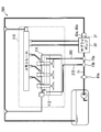
- FIG. 1 is a diagram illustrating an overall configuration of a fuel supply device according to a first embodiment of the present disclosure.
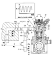
- FIG. 2 is a diagram showing details of the supply pump and each low-pressure pipe.
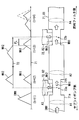
- FIG. 3 is a diagram for explaining the effect of reducing the peak pressure by the auxiliary low-pressure pipe,
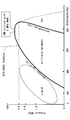
- FIG. 4 is a Mollier diagram of dimethyl ether,
- FIG. 5 is a diagram illustrating an overall configuration of a fuel supply device according to a second embodiment of the present disclosure,
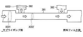
- FIG. 6 is a diagram illustrating a modification of the main low-pressure pipe and the sub-low pressure pipe.
- a fuel supply device 100 according to the first embodiment of the present disclosure shown in FIG. 1 is mounted on a vehicle together with a fuel tank 190 and an internal combustion engine 110.
- the fuel supply device 100 supplies the liquefied gas fuel stored in the fuel tank 190 to the internal combustion engine 110.
- a part of the liquefied gas fuel supplied to the internal combustion engine 110 is returned to the fuel tank 190.
- the fuel tank 190 stores dimethyl ether (DME) which is a kind of liquefied gas fuel.
- DME dimethyl ether
- the DME fuel in the fuel tank 190 is liquefied by being pressurized at a pressure corresponding to the fuel vapor pressure.
- the fuel tank 190 is provided with a safety valve. The safety valve opens when the pressure in the fuel tank 190 exceeds a predetermined upper limit pressure.
- the internal combustion engine 110 is stored in the engine room of the vehicle.
- the internal combustion engine 110 is specifically a diesel engine.
- the internal combustion engine 110 compresses the DME fuel injected from the injector 40 disposed in each cylinder in each cylinder.
- the internal combustion engine 110 converts thermal energy of DME fuel combusted by compression in each combustion chamber into power.
- the internal combustion engine 110 is provided with a common rail 30 in addition to the injector 40 described above.
- the injector 40 supplies DME fuel into each cylinder of the internal combustion engine 110.
- the injector 40 is inserted into a through hole formed in the cylinder head 111 of the internal combustion engine 110 to expose the injection hole in the combustion chamber.
- the injector 40 injects DME fuel from the injection hole exposed to the combustion chamber based on the input control signal.
- the common rail 30 is a tubular member formed of a metal material such as a steel material.
- the common rail 30 accumulates the DME fuel supplied by the fuel supply apparatus 100 while maintaining the pressure.
- the common rail 30 supplies DME fuel to each injector 40.
- a pressure regulating valve 31 is provided on the common rail 30. The pressure regulating valve 31 is opened when the fuel pressure in the common rail 30 exceeds a predetermined upper limit pressure.
- the fuel supply apparatus 100 includes a fuel line 80, a feed pump 10, and a supply pump 20.
- the fuel line 80 forms a fuel flow path through which the DME fuel flows between the fuel tank 190 and the internal combustion engine 110.
- the fuel line 80 includes a main low pressure pipe 81, a high pressure pipe 83, a distribution pipe 84, a main return pipe 85, a rail return pipe 87, an injector return pipe 88, and the like. These pipes are formed of a rubber hose material reinforced with polyester or aramid or the like, a curved metal tubular member, or the like.
- the main low-pressure pipe 81 connects the feed pump 10 and the supply pump 20.
- the main low-pressure pipe 81 forms a first fuel flow path 71 through which the DME fuel stored in the fuel tank 190 flows between the feed pump 10 and the supply pump 20.
- the main low-pressure pipe 81 is provided with a fuel filter 81a.
- the fuel filter 81 a can remove foreign substances from the DME fuel flowing through the first fuel flow path 71.
- the high-pressure pipe 83 connects the supply pump 20 and the common rail 30.
- the high-pressure pipe 83 forms a high-pressure fuel flow path through which the high-pressure DME fuel discharged by the supply pump 20 flows between the supply pump 20 and the common rail 30.
- the distribution pipe 84 connects the common rail 30 and each injector 40.
- the distribution pipe 84 forms a distribution flow path for circulating the high-pressure DME fuel stored in the common rail 30 between the common rail 30 and the injector 40.
- the main return pipe 85 connects the leaked fuel discharge part 21 of the supply pump 20 and the fuel tank 190.
- the main return pipe 85 forms a first return flow path 75 through which the leaked fuel discharged from the leak fuel discharge unit 21 circulates between the leak fuel discharge unit 21 and the fuel tank 190.
- the main return pipe 85 is provided with an overflow valve 85a and a thermostat 85b.
- the overflow valve 85a is opened when the pressure of the fuel discharged from the leak fuel discharge unit 21 exceeds a predetermined threshold pressure (for example, 3 MPa).
- the thermostat 85b is arranged in parallel with the overflow valve 85a.
- the thermostat 85b opens when the temperature of the fuel discharged from the leak fuel discharge unit 21 exceeds a predetermined threshold temperature (for example, 90 ° C.).
- the overflow valve 85a and the thermostat 85b allow the DME fuel to return from the supply pump 20 toward the fuel tank 190 by opening the valve.
- the rail return pipe 87 connects the pressure regulating valve 31 of the common rail 30 and the main return pipe 85.
- the rail return pipe 87 forms a rail return flow path for joining surplus fuel discharged from the common rail 30 to the first return flow path 75. Excess fuel from the common rail 30 is returned to the fuel tank 190 along with the leaked fuel and the like through the rail return channel and the first return channel 75.
- the injector return pipe 88 connects the fuel gallery 112 of the cylinder head 111 and the main return pipe 85.
- the fuel gallery 112 extends in the cylinder head 111 along the axial direction of the crankshaft. Leak fuel is discharged from each injector 40 to the fuel gallery 112.
- the injector return pipe 88 forms an injector return flow path that joins the leaked fuel discharged to the fuel gallery 112 to the first return flow path 75.
- the injector return pipe 88 is provided with a back pressure valve 88a and a thermostat 88b.
- the back pressure valve 88a opens when the fuel pressure in the fuel gallery 112 exceeds a predetermined threshold pressure (for example, 3 MPa).
- the thermostat 88b is arranged in parallel with the back pressure valve 88a.
- the thermostat 88b opens when the temperature of the fuel in the fuel gallery 112 exceeds a predetermined threshold temperature (for example, 90 ° C.).
- the back pressure valve 88a and the thermostat 88b allow the DME fuel to return from the fuel gallery 112 toward the fuel tank 190 by opening the valve.
- the feed pump 10 is an electric pump disposed inside the fuel tank 190.
- the feed pump 10 sucks the DME fuel stored in the fuel tank 190 using the power of the electric motor.
- the feed pump 10 adds a feed pressure (for example, about 3 MPa) to the DME fuel to increase the pressure, and feeds the DME fuel toward the supply pump 20 through the first fuel flow path 71.
- the supply pump 20 is a plunger pump, for example, and is driven by the internal combustion engine 110.
- the supply pump 20 sucks the DME fuel discharged from the feed pump 10 into the pressurizing chamber 23.
- the supply pump 20 pressurizes the DME fuel in the pressurizing chamber 23 by a plunger 22 that is reciprocally displaced using the power of the internal combustion engine 110.
- the pressurized DME fuel is pumped from the supply pump 20 toward the common rail 30.
- the supply pump 20 has the above-described leak fuel discharge unit 21.
- the leak fuel discharge unit 21 discharges leak fuel generated in the supply pump 20 to the first return flow path 75.
- the leak fuel is a fuel that leaks through a clearance formed around a sliding portion such as the plunger 22.
- the supply pump 20 sucks fuel into the pressurizing chamber 23 and discharges the fuel from the pressurizing chamber 23, thereby causing pressure pulsation in the fuel gallery (see FIG. 2).
- the pressure pulsation generated from the supply pump 20 is propagated to each component of the fuel line 80 as a pressure water hammer.
- the fuel line 80 is provided with the auxiliary low-pressure pipe 82 and the auxiliary return pipe 86 shown in FIGS.
- the sub-low pressure pipe 82 connects the main low pressure pipe 81 and the cylinder head 111 between the supply pump 20 and the fuel filter 81a.
- the sub low pressure pipe 82 extends in a direction substantially orthogonal to the main low pressure pipe 81.
- the sub low pressure pipe 82 forms a second fuel flow path 72 that reciprocates between the main low pressure pipe 81 and the cylinder head 111.
- Each end of the sub-low pressure pipe 82 is connected to the first fuel flow path 71 by two joint members. Of the two joint members, one close to the supply pump 20 forms a low-pressure branch 73a, and the other close to the feed pump 10 forms a low-pressure junction 73b.
- the second fuel flow path 72 is branched from the first fuel flow path 71 by a low pressure branching portion 73a.
- the second fuel flow path 72 forms a DME fuel flow path in parallel with the first fuel flow path 71 and merges with the first fuel flow path 71 at the low-pressure merging portion 73b.
- the flow path length from the low pressure branch portion 73a to the low pressure merge portion 73b in the second fuel flow channel 72 is different from the flow path length from the low pressure branch portion 73a to the low pressure merge portion 73b in the first fuel flow channel 71.
- the channel length of the second fuel channel 72 is set to be, for example, about 1 meter longer than the channel length of the first fuel channel 71.
- the temperature of the fuel flowing through the second fuel flow path 72 is different from the temperature of the fuel flowing through the first fuel flow path 71.
- the sub-low pressure pipe 82 has a low-pressure temperature raising portion 74 that raises the temperature of the DME fuel flowing through the second fuel flow path 72.
- the low pressure heating unit 74 is provided in the cylinder head 111.
- the low pressure temperature raising portion 74 forms a part of the second fuel flow path 72 in the cylinder head 111.
- the low pressure heating unit 74 heats the DME flowing through the second fuel flow path 72 in the cylinder head 111 with heat generated in the internal combustion engine 110.
- the low-pressure temperature raising unit 74 can keep the DME fuel at a high temperature by transferring the heat of at least one of the cooling water and the lubricating oil of the internal combustion engine 110 to the DME fuel flowing through the second fuel flow path 72.
- the branching in the low-pressure branching portion 73a increases the channel area.
- a section that is closer to the supply pump 20 than the low-pressure branch portion 73a is a pre-branch section 71a
- a section between the low-pressure branch section 73a and the low-pressure junction section 73b is a post-branch section 71b.
- the flow passage area A1 in the pre-branch section 71a is based on the total flow passage area of the flow passage area A2 in the post-branch section 71b and the flow passage area A3 of the second fuel flow path 72 branched by the low-pressure branch portion 73a. Is also set small (see also FIG. 3).
- the post-branch section 71b and the second fuel flow path 72 are expanded in flow path area. Therefore, the flow path area A2 in the post-branch section 71b and the flow path area A3 of the second fuel flow path 72 are substantially the same as or larger than the flow path area A1 in the pre-branch section 71a. Has been. Furthermore, the flow path area A4 after the merge is larger than the flow path area of the low-pressure merge part 73b, and is substantially the same as the flow path area A4 of the pre-branch section 71a.
- the secondary return pipe 86 connects the main return pipe 85 and the cylinder head 111 between the supply pump 20 and the overflow valve 85a.
- the sub return pipe 86 extends in a direction substantially orthogonal to the main return pipe 85.
- the sub return pipe 86 forms a second return flow path 76 that reciprocates between the main return pipe 85 and the cylinder head 111.
- Each end of the sub return pipe 86 is connected to the main return pipe 85 by two joint members. Of the two joint members, one close to the supply pump 20 forms a return branch 77a, and the other far from the supply pump 20 forms a return junction 77b.
- the second return channel 76 is branched from the first return channel 75 at the return branching portion 77a.
- the second return flow path 76 forms a flow path of return fuel in parallel with the first return flow path 75, and merges with the first return flow path 75 at the return merge portion 77b.
- the flow path length from the return branch part 77a to the return merge part 77b in the second return flow path 76 is different from the flow path length from the return branch part 77a to the return merge part 77b in the first return flow path 75.
- the temperature of the fuel flowing through the second return flow path 76 is different from the temperature of the fuel flowing through the first return flow path 75.
- the sub return pipe 86 has a return temperature raising portion 78 for raising the temperature of the DME fuel flowing through the second return flow path 76.
- the return temperature raising unit 78 is provided in the cylinder head 111 in the same manner as the low pressure temperature raising unit 74.
- the return temperature raising unit 78 forms a part of the second return channel 76 in the cylinder head 111.
- the return temperature raising unit 78 heats the DME flowing through the second return flow path 76 in the cylinder head 111 with heat generated in the internal combustion engine 110.
- the return temperature raising unit 78 can keep the DME fuel at a high temperature by transmitting the heat of at least one of the cooling water and the lubricating oil of the internal combustion engine 110 to the DME fuel flowing through the second return flow path 76.
- Branch at the return branch portion 77a expands the flow area. Specifically, in the first return flow path 75, a section that is closer to the supply pump 20 than the return branch section 77a is a section before branch 75a, and a section between the return branch section 77a and the return junction section 77b is a section after branch 75b. And The flow path area in the pre-branch section 75a is smaller than the total flow path area of the flow path area in the post-branch section 75b and the flow path area of the second return flow path 76 branched by the return branch section 77a. Is set.
- the pressure water hammer (intake water hammer) IWH shown in FIGS. 2 and 3 flows from the fuel gallery of the supply pump 20 to the first fuel flow path 71. Propagates to the pre-branch section 71a (see t1 in FIG. 3).
- the suction water hammer IWH is divided into a first water hammer component WH1 propagating through the first fuel flow path 71 and a second water hammer component WH2 propagating through the second fuel flow path 72 in the low pressure branch 73a ( (See Fig. 3 t2).
- the energy of the suction water hammer IWH can be substantially divided into the first water hammer component WH1 and the second water hammer component WH2 by the division in the low pressure branching portion 73a.
- each peak pressure of the first water hammer component WH1 and the second water hammer component WH2 is about 50% of the peak pressure of the suction water hammer IWH.
- the loss Water head is generated according to the bending of the flow path provided in the low pressure branch 73a and the expansion and contraction of the flow path area provided in the front and rear of the low pressure branch 73a and the low pressure merge part 73b and the second fuel flow path 72. This loss head can attenuate each water hammer component WH1, WH2.
- each water hammer component WH1, WH2 propagates substantially at the speed of sound.
- the speed of sound increases as the temperature of the DME fuel decreases and increases as the pressure of the DME fuel increases. Due to the temperature raising action of the low-pressure temperature raising portion 74, the speed of sound in the DME fuel flowing through the second fuel flow path 72 is slower than the speed of sound in the DME fuel flowing through the first fuel flow path 71. Therefore, the propagation speed of the second water hammer component WH2 is slower than the propagation speed of the first water hammer component WH1. Further, the channel length of the second fuel channel 72 is longer than the channel length of the first fuel channel 71. As described above, the second water hammer component WH2 causes a phase delay PL with respect to the first water hammer component WH1 immediately before the low pressure branching portion 73a (see t3 in FIG. 3).
- the auxiliary low-pressure pipe 82 delays the arrival of the second water hammer component WH2 to the low-pressure confluence 73b with respect to the first water hammer component WH1, and reduces the peak pressure of the second water hammer component WH2. Can be made. Therefore, the sub-low pressure pipe 82 has the peak pressure of the pressure water hammer propagating from the low-pressure junction 73b to the feed pump 10 (see FIG. 1) when the sub-low pressure pipe 82 is not provided (see the two-point difference line in FIG. 3). In comparison, it can be reduced to about half.
- the pressure water hammer propagating from the leak fuel discharge part 21 shown in FIG. 1 to the pre-branch section 75a of the first return flow path 75 propagates through the first return flow path 75 in the return branch part 77a. It is divided into a water hammer component and a second water hammer component propagating through the second return channel 76. According to the difference between the fuel temperature and the flow path length between the first return flow path 75 and the second return flow path 76, the phase of the second water hammer component is the first water just before the return branching portion 77a. Delays relative to the phase of the strike component.
- the waveform of the second water hammer component gradually becomes gentle in the process of propagating through the second return flow path 76, and changes to a waveform in which the peak pressure is reduced. To do.
- the auxiliary return pipe 86 can delay the arrival of the second water hammer component to the return merge portion 77b with respect to the first water hammer component and reduce the peak pressure of the second water hammer component. it can. Therefore, the sub-return pipe 86 can reduce the peak pressure of the pressure water hammer propagating from the return junction 77b to the overflow valve 85a to about half compared with the case where the sub-return pipe 86 is not provided.
- a difference in fuel temperature and channel length is provided between the first fuel channel 71 and the second fuel channel 72.
- a phase shift may occur between the first water hammer component WH1 and the second water hammer component WH2 in the low pressure merging portion 73b. Therefore, even if the two water hammer components WH1 and WH2 are combined, the peak pressure of water hammer due to pressure pulsation can be reduced as compared with the case where only the first fuel flow channel 71 is propagated.
- a difference in fuel temperature and channel length is also provided between the first return channel 75 and the second return channel 76.
- a phase shift may occur between the first water hammer component and the second water hammer component in the return junction 77b. Therefore, even if two water hammer components are combined, the peak pressure of water hammer due to pressure pulsation can be reduced as compared with the case where only the first return flow path 75 is propagated.
- the peak pressure of pressure pulsation can be reduced by the highly feasible configuration of providing two fuel flow paths.
- the fuel filter 81a and the configurations such as the overflow valve 85a and the thermostat 85b are protected from water hammer due to pressure pulsation.
- the peak pressure is reduced while maintaining the DME fuel in the second fuel flow path 72 and the second return flow path 76 in a liquid phase state (see the broken line area in FIG. 4).
- the effect is demonstrated.
- the fuel supply device does not attenuate the pressure pulsation by the accumulator effect by putting the DME fuel into the gas-liquid two-phase state or the gas-phase state, but uses the loss head in the liquid phase state.
- the pressure pulsation can be reduced.
- the heat generated in the internal combustion engine 110 is used to suppress consumption of energy for raising the temperature of the fuel, and then the second fuel passage 72 and the second return passage 76. Reduction of the propagation speed of each second water hammer component transmitted through the water is realized.
- the waveform of the second water hammer component changes to a waveform with a reduced peak pressure in the process of propagation. . Therefore, the peak pressure can be reliably reduced in a state where the two water hammer components are synthesized at the low-pressure merging portion 73b and the return merging portion 77b.
- the area of the flow path through which the pressure water hammer propagates is expanded by the branching at the low pressure branching portion 73a and the return branching portion 77a.
- Such expansion of the flow path area causes a loss head.
- the feed pressure of the fuel discharged from the feed pump 10 is a liquid such as light oil so that the fuel is not vaporized. It becomes higher than the feed pressure of the form which supplies fuel. Therefore, in the fuel supply apparatus 100 that supplies DME fuel, the peak pressure generated by pressure water hammer shows a higher value than the peak pressure of the form that supplies liquid fuel. For this reason, the configuration in which the auxiliary low pressure pipe 82 and the auxiliary return pipe 86 are provided to reduce the peak pressure is applied to the fuel supply device 100 that supplies DME fuel, thereby exhibiting a remarkable effect in protecting the fuel filter 81a and the like. it can.
- the feed pump 10 corresponds to a low pressure pump
- the supply pump 20 corresponds to a high pressure pump
- the main low pressure pipe 81 corresponds to a first low pressure path member
- the sub low pressure pipe 82 and the cylinder head 111 Corresponds to the second low-pressure path member.
- the main return pipe 85 corresponds to the first return path member
- the sub return pipe 86 and the cylinder head 111 correspond to the second return path member
- the internal combustion engine 110 corresponds to the engine.
- the second embodiment of the present disclosure shown in FIG. 5 is a modification of the first embodiment. From the fuel line 280 according to the second embodiment, a configuration corresponding to the auxiliary return pipe 86 (see FIG. 1) of the first embodiment is omitted.
- the sub-low pressure pipe 282 has two pipe members. Each piping member is connected to a section between the supply pump 20 and the fuel filter 81 a in the first fuel flow path 71 and both ends of the fuel gallery 112 provided in the cylinder head 111.
- the second fuel channel 272 that reciprocates between the first fuel channel 71 and the fuel gallery 112 is formed. At least a part of the second fuel flow path 272 is formed by the fuel gallery 112.
- the flow path length from the low pressure branching portion 73 a to the low pressure confluence portion 73 b is different from the flow length of the first fuel flow channel 71, and more than that of the first fuel flow channel 71. Have been long.
- the DME fuel flowing through the fuel gallery 112 in the second fuel flow path 272 is heated by heat transmitted from the cooling water and lubricating oil of the internal combustion engine 110, heat transmitted from the fuel chamber, and the like. As a result, the DME fuel in the second fuel channel 272 maintains a higher temperature than the DME fuel in the first fuel channel 71.
- the peak pressure of the pressure pulsation can be reduced by producing the same effect as the first embodiment.
- the feasibility of the configuration including the second fuel flow path 272 is further increased.
- the temperature of the fuel can be reliably increased by the engine heat of the internal combustion engine 110.
- the fuel gallery 112 has a complicated flow path shape, the second water hammer component that has passed through the fuel gallery 112 is reliably attenuated. Therefore, the effect of reducing the peak pressure of the pressure pulsation is more reliably exhibited.
- the auxiliary low pressure pipe 282 corresponds to a second low pressure passage member.
- each of the flow path areas A2 and A3 after branching is approximately the same as the flow channel area A1 before branching.
- the effect of attenuating the pressure pulsation is remarkably exhibited by the contraction and expansion after the branching in the low-pressure branching part 73a, and further by the contraction and expansion after the joining in the low-pressure joining part 73b.
- the flow passage areas of the main low-pressure pipe and the sub-low pressure pipe after branching may be sufficiently larger than the flow passage area of the main low-pressure pipe before branching.
- the main low-pressure pipe 381 and the sub-low pressure pipe 382 of the modified example shown in FIG. 6 even if each flow passage area A302, A303 after branching is smaller than the flow passage area A301 before branching, pressure pulsation is caused. A damping action can be exerted.
- the sub-pipe is provided for each of the main low-pressure pipe and the main return pipe.
- sub piping was provided only in main low pressure piping among main low pressure piping and main return piping.
- the sub piping may be provided only in the main return piping among the main low pressure piping and the main return piping.
- the sub piping may be provided in the high pressure piping.
- the overflow valve 85a and the thermostat 85b can be directly attached to the leak fuel discharge portion 21 of the supply pump 20, as shown in FIG.
- both the temperature difference and the channel length difference are set between the first fuel channel and the second fuel channel.
- only the temperature of the circulating DME fuel may be different after the pipe lengths of the main low-pressure pipe and the sub-low pressure pipe are substantially equalized.
- the cycle is about 8 ms. If the speed of sound is 500 meters per second, a difference in flow path (pipe) length of about 2 meters is required to cause a phase delay of 4 ms as a half wavelength. Furthermore, when the feed pressure of the feed pump 10 is 3 MPa as described above and the temperature difference between the first fuel flow path and the second fuel flow path is 40 ° C., a flow path length difference of about 1 meter can be provided. For example, a phase delay of 4 ms as a half wavelength can occur.
- the DME fuel in the second fuel flow path and the second return flow path is warmed by the engine heat of the internal combustion engine 110.
- an electric heating device such as a heater as the low-pressure temperature raising portion and the return temperature raising portion.
- the thermal conductivity is high between the outer peripheral surface of the injector and the inner peripheral surface of the through hole of the cylinder head.
- a copper tube or the like can be provided. The copper tube can support the temperature rise of the DME fuel by efficiently transferring the combustion heat to the DME fuel of the fuel gallery 112.
- the temperature difference of the DME fuel can be caused by the function of a cooler that cools the DME fuel in the first fuel flow path and the first return flow path.
- the difference in the channel length is provided by making the first fuel channel shorter than the second fuel channel.
- the difference in flow path length may be provided by making the first fuel flow path longer than the second fuel flow path.
- the temperature difference is set by making the fuel temperature in the second fuel flow path higher than the fuel temperature in the first fuel flow path.
- it is possible to cause a temperature difference by making the fuel temperature in the first fuel channel higher than the fuel temperature in the second fuel channel.
- a part of the second fuel flow path and the second return flow path is formed in the cylinder head, so that the cylinder head 111 also serves as the second low pressure path member and the second return path member.
- the second fuel flow path and the second return flow path may be formed in other parts of the main body structure system of the internal combustion engine, such as a cylinder block, and the DME fuel may be heated.
- the auxiliary low pressure pipe and the secondary return pipe are arranged closer to the internal combustion engine than the main low pressure pipe and the main return pipe. Good.
- the water hammer pressure is leveled by generating a loss head by changing the flow path shape such as branching, bending, expansion, and reduction.
- the peak pressure can be reduced if a difference in fuel temperature or a difference in flow path length is provided.
- the present disclosure is not limited to the diesel engine, and the fuel supply that supplies fuel to other internal combustion engines and external combustion engines. It is also applicable to the device.
- the fuel supplied by the fuel supply device is not limited to DME fuel, but may be fuel containing DME, liquefied petroleum gas, compressed natural gas, light oil, gasoline, or the like.
Landscapes
- Engineering & Computer Science (AREA)
- Chemical & Material Sciences (AREA)
- Combustion & Propulsion (AREA)
- Mechanical Engineering (AREA)
- General Engineering & Computer Science (AREA)
- Chemical Kinetics & Catalysis (AREA)
- General Chemical & Material Sciences (AREA)
- Oil, Petroleum & Natural Gas (AREA)
- Fuel-Injection Apparatus (AREA)
Abstract
燃料供給装置は、燃料タンク(190)に貯留された燃料を機関(110)へ供給する燃料供給装置であって、燃料タンクの燃料を圧送する低圧ポンプ(10)と、低圧ポンプから吐出された燃料を昇圧して機関に圧送する高圧ポンプ(20)と、低圧ポンプから高圧ポンプまでの第一燃料流路(71)、を形成する第一低圧路部材(81,381)と、低圧分岐部(73a)にて第一燃料流路から分岐され、低圧合流部(73b)にて第一燃料流路に合流する第二燃料流路(72,272)、を形成する第二低圧路部材(82,282,382)と、を備え、第二燃料流路は、流通する燃料の温度及び低圧分岐部から低圧合流部までの流路長さの少なくとも一方が第一燃料流路とは異なる。
Description
本出願は、2015年6月3日に出願された日本特許出願番号2015-113420号に基づくもので、ここにその記載内容を援用する。
本開示は、燃料タンクに貯留された燃料を機関へ供給する燃料供給装置に関する。
燃料を機関へ供給する燃料供給装置は、燃料タンクの燃料を圧送する低圧ポンプと、低圧ポンプから吐出された燃料を昇圧して機関に圧送する高圧ポンプとを備えている。このような構成では、特許文献1に記載されているように、高圧ポンプを発生源とする圧力脈動が発生し得る。
こうした圧力脈動を抑えるために、特許文献1に開示の構成では、高圧ポンプの燃料ギャラリよりも流路面積の大きい流路拡大配管が、低圧ポンプから高圧ポンプまでの燃料流路と燃料ギャラリとの間に設けられている。加えて、燃料ギャラリにおいて流路拡大配管とは反対側の端部には、オーバーフロー弁が設けられている。以上の構成では、燃料ギャラリと流路拡大配管との境界部で反射した位相反転反射波は、燃料ギャラリとオーバーフロー弁との境界部にて反射した正転反射波と合成される。その結果、燃料ギャラリ内の圧力脈動の低減が図られている。
ここで、特許文献1のような流路拡大配管を設ける構成は、燃料ギャラリ内に生じる圧力脈動を低減可能であるものの、圧力脈動は、流路拡大配管を通過し、高圧ポンプと繋がる燃料流路を通じて、燃料系の他の構成に伝播できる。そのため、圧力脈動に起因する不具合を低減させるために、高圧ポンプから他の構成へと伝播する圧力脈動、特にピーク圧力を抑える構成が必要とされていた。
本開示の目的は、高圧ポンプから他の構成へ向けて伝播する圧力脈動のピーク圧力を抑えることが可能な燃料供給装置を提供することにある。
本開示の第一態様による燃料供給装置は、燃料タンクに貯留された燃料を機関へ供給する燃料供給装置であって、燃料タンクの燃料を圧送する低圧ポンプと、低圧ポンプから吐出された燃料を昇圧して機関に圧送する高圧ポンプと、低圧ポンプから高圧ポンプまでの第一燃料流路、を形成する第一低圧路部材と、低圧分岐部にて第一燃料流路から分岐され、低圧合流部にて第一燃料流路に合流する第二燃料流路、を形成する第二低圧路部材と、を備え、第二燃料流路は、流通する燃料の温度及び低圧分岐部から低圧合流部までの流路長さの少なくとも一方が第一燃料流路とは異なる。
この開示によれば、低圧ポンプから高圧ポンプまでの第一燃料流路から、第二燃料流路が分岐されているため、高圧ポンプを発生源とする圧力脈動は、第一燃料流路を伝播する成分と、第二燃料流路を伝播する成分とに分けられ得る。これら第一燃料流路と第二燃料流路には、流通する燃料の温度及び低圧分岐部から低圧合流部までの流路長さの少なくとも一方に差が設けられている。故に、低圧合流部において、第二燃料流路を伝播した成分と、第一燃料流路を伝播した成分との間には、位相のずれが生じている。そのため、二つの燃料流路をそれぞれ伝播した成分が合成されても、圧力脈動のピーク圧力は、第一燃料流路のみを伝播した場合と比較して、低減され得る。以上のように、二つの燃料流路を設けるという実現性の高い構成により、圧力脈動のピーク圧力が低減可能となる。
本開示の第一態様による燃料供給装置は、燃料タンクに貯留された燃料を機関へ供給する燃料供給装置であって、低圧ポンプによって燃料タンクから圧送される燃料を昇圧する高圧ポンプと、高圧ポンプから燃料タンクへ向けて燃料を戻す第一リターン流路、を形成する第一リターン路部材と、戻り分岐部にて第一リターン流路から分岐され、戻り合流部にて第一リターン流路に合流する第二リターン流路、を形成する第二リターン路部材と、を備え、第二リターン流路は、流通する燃料の温度及び戻り分岐部から戻り合流部までの流路長さの少なくとも一方が第一リターン流路とは異なる。
この開示によれば、高圧ポンプから燃料タンクへと燃料を戻す第一リターン流路から、第二リターン流路が分岐されているため、高圧ポンプを発生源とする圧力脈動は、第一リターン流路を伝播する成分と、第二リターン流路を伝播する成分とに分けられ得る。これら第一リターン流路と第二リターン流路には、流通する燃料の温度及び戻り分岐部から戻り合流部までの流路長さの少なくとも一方に差が設けられている。故に、戻り合流部において、第二リターン流路を伝播した成分と、第一リターン流路を伝播した成分との間には、位相のずれが生じている。そのため、二つのリターン流路をそれぞれ伝播した成分が合成されても、圧力脈動のピーク圧力は、第一リターン流路のみを伝播した場合と比較して、低減され得る。以上のように、二つのリターン流路を設けるという実現性の高い構成により、圧力脈動のピーク圧力が低減可能となる。
本開示についての上記目的およびその他の目的、特徴や利点は、添付の図面を参照しながら下記の詳細な記述により、より明確になる。その図面は、
図1は、本開示の第一実施形態による燃料供給装置の全体構成を示す図であり、
図2は、サプライポンプ及び各低圧配管の詳細を示す図であり、
図3は、副低圧配管によるピーク圧力の低減効果を説明するための図であり、
図4は、ジメチルエーテルのモリエル線図であり、
図5は、本開示の第二実施形態による燃料供給装置の全体構成を示す図であり、
図6は、主低圧配管と副低圧配管の変形例を示す図である。
以下、本開示の複数の実施形態を図面に基づいて説明する。尚、各実施形態において対応する構成要素には同一の符号を付すことにより、重複する説明を省略する場合がある。各実施形態において構成の一部分のみを説明している場合、当該構成の他の部分については、先行して説明した他の実施形態の構成を適用することができる。また、各実施形態の説明において明示している構成の組み合わせばかりではなく、特に組み合わせに支障が生じなければ、明示していなくても複数の実施形態の構成同士を部分的に組み合わせることができる。そして、複数の実施形態及び変形例に記述された構成同士の明示されていない組み合わせも、以下の説明によって開示されているものとする。
(第一実施形態)
図1に示す本開示の第一実施形態による燃料供給装置100は、燃料タンク190及び内燃機関110と共に車両に搭載されている。燃料供給装置100は、燃料タンク190に貯留された液化ガス燃料を内燃機関110に供給する。内燃機関110へと供給された液化ガス燃料の一部は、燃料タンク190に還流される。
図1に示す本開示の第一実施形態による燃料供給装置100は、燃料タンク190及び内燃機関110と共に車両に搭載されている。燃料供給装置100は、燃料タンク190に貯留された液化ガス燃料を内燃機関110に供給する。内燃機関110へと供給された液化ガス燃料の一部は、燃料タンク190に還流される。
燃料タンク190は、液化ガス燃料の一種であるジメチルエーテル(Dimethyl Ether,DME)を貯留している。燃料タンク190内のDME燃料は、燃料蒸気圧に応じた圧力で加圧されることにより、液化されている。燃料タンク190には、安全弁が設けられている。安全弁は、燃料タンク190内の圧力が所定の上限圧力を超えた場合に開弁する。
内燃機関110は、車両のエンジンルーム内に格納されている。内燃機関110は、具体的にはディーゼル機関である。内燃機関110は、各気筒に配置されたインジェクタ40から噴射されるDME燃料を各気筒内にて圧縮する。内燃機関110は、各燃焼室において圧縮により燃焼するDME燃料の熱エネルギを、動力に変換する。内燃機関110には、上述のインジェクタ40に加えて、コモンレール30が設けられている。
インジェクタ40は、内燃機関110の各気筒内にDME燃料を供給する。インジェクタ40は、内燃機関110のシリンダヘッド111に形成された貫通孔に挿入されることにより、燃焼室に噴孔を露出させている。インジェクタ40は、入力される制御信号に基づいて、燃焼室に露出した噴孔からDME燃料を噴射する。
コモンレール30は、鉄鋼材等の金属材料によって形成された管状の部材である。コモンレール30は、燃料供給装置100によって供給されたDME燃料を、圧力を維持させたまま蓄積する。コモンレール30は、各インジェクタ40にDME燃料を供給する。コモンレール30には、調圧弁31が設けられている。調圧弁31は、コモンレール30内の燃料圧力が所定の上限圧力を超えた場合に開弁する。
燃料供給装置100は、燃料ライン80、フィードポンプ10、及びサプライポンプ20を備えている。燃料ライン80は、燃料タンク190と内燃機関110との間において、DME燃料を流通させる燃料の流路を形成している。燃料ライン80は、主低圧配管81、高圧配管83、分配配管84、主リターン配管85、レールリターン配管87、及びインジェクタリターン配管88等によって構成されている。これらの配管は、ポリエステル又はアラミド等により補強されたゴム製のホース材、及び湾曲させた金属製の管状部材等によって形成されている。
主低圧配管81は、フィードポンプ10とサプライポンプ20とを繋いでいる。主低圧配管81は、フィードポンプ10からサプライポンプ20までの間に、燃料タンク190に貯留されたDME燃料を流通させる第一燃料流路71を形成している。主低圧配管81には、燃料フィルタ81aが設けられている。燃料フィルタ81aは、第一燃料流路71を流れるDME燃料から異物を取り除くことができる。
高圧配管83は、サプライポンプ20とコモンレール30とを繋いでいる。高圧配管83は、サプライポンプ20からコモンレール30までの間に、サプライポンプ20によって吐出された高圧のDME燃料を流通させる高圧燃料流路を形成している。分配配管84は、コモンレール30と各インジェクタ40とを繋いでいる。分配配管84は、コモンレール30からインジェクタ40までの間に、コモンレール30に蓄えられた高圧のDME燃料を流通させる分配流路を形成している。
主リターン配管85は、サプライポンプ20のリーク燃料排出部21と燃料タンク190とを繋いでいる。主リターン配管85は、リーク燃料排出部21から燃料タンク190までの間に、リーク燃料排出部21から排出されるリーク燃料等を流通させる第一リターン流路75を形成している。主リターン配管85には、オーバーフロー弁85a及びサーモスタット85bが設けられている。
オーバーフロー弁85aは、リーク燃料排出部21から排出される燃料の圧力が所定の閾値圧力(例えば3MPa)を超えた場合に開弁する。サーモスタット85bは、オーバーフロー弁85aと並列で配置されている。サーモスタット85bは、リーク燃料排出部21から排出される燃料の温度が所定の閾値温度(例えば90℃)を超えた場合に開弁する。オーバーフロー弁85a及びサーモスタット85bは、サプライポンプ20から燃料タンク190へ向かって戻るDME燃料の流通を、開弁によって許容する。
レールリターン配管87は、コモンレール30の調圧弁31と主リターン配管85とを繋いでいる。レールリターン配管87は、コモンレール30から排出される余剰燃料を、第一リターン流路75へ合流させるレールリターン流路を形成している。コモンレール30からの余剰燃料は、レールリターン流路及び第一リターン流路75を通じて、リーク燃料等と共に燃料タンク190に戻される。
インジェクタリターン配管88は、シリンダヘッド111の燃料ギャラリ112と主リターン配管85とを繋いでいる。燃料ギャラリ112は、クランクシャフトの軸方向に沿って、シリンダヘッド111内を延伸している。燃料ギャラリ112には、各インジェクタ40から、リーク燃料が排出される。インジェクタリターン配管88は、燃料ギャラリ112に排出されたリーク燃料を、第一リターン流路75へ合流させるインジェクタリターン流路を形成している。インジェクタリターン配管88には、背圧弁88a及びサーモスタット88bが設けられている。
背圧弁88aは、燃料ギャラリ112の燃料の圧力が所定の閾値圧力(例えば3MPa)を超えた場合に開弁する。サーモスタット88bは、背圧弁88aと並列で配置されている。サーモスタット88bは、燃料ギャラリ112の燃料の温度が所定の閾値温度(例えば90℃)を超えた場合に開弁する。背圧弁88a及びサーモスタット88bは、燃料ギャラリ112から燃料タンク190へ向かって戻るDME燃料の流通を、開弁によって許容する。
フィードポンプ10は、燃料タンク190の内部に配置された電動ポンプである。フィードポンプ10は、電動モータの動力を用いて、燃料タンク190に貯留されたDME燃料を吸い込む。フィードポンプ10は、DME燃料にフィード圧力(例えば3MPa程度)を加えて昇圧させ、第一燃料流路71を通じてサプライポンプ20へ向けて圧送する。
サプライポンプ20は、例えばプランジャポンプ等であり、内燃機関110によって駆動される。サプライポンプ20は、フィードポンプ10から吐出されたDME燃料を加圧室23に吸入させる。サプライポンプ20は、内燃機関110の動力を用いて往復変位させるプランジャ22により、加圧室23のDME燃料を加圧する。昇圧されたDME燃料は、サプライポンプ20からコモンレール30へ向けて圧送される。
サプライポンプ20は、上述したリーク燃料排出部21を有している。リーク燃料排出部21は、サプライポンプ20にて生じるリーク燃料を第一リターン流路75に排出する。リーク燃料は、プランジャ22等の摺動部の周囲に形成されたクリアランスを通じて漏れ出る燃料等である。
サプライポンプ20は、加圧室23に燃料を吸入し、加圧室23から燃料を吐出する作動により、燃料ギャラリ内に圧力脈動を生じさせる(図2参照)。こうしたサプライポンプ20を発生源とする圧力脈動は、燃料ライン80の各構成に圧力水撃として伝播する。この圧力水撃による影響を抑えるため、燃料ライン80には、図1及び図2に示す副低圧配管82及び副リターン配管86が設けられている。
副低圧配管82は、サプライポンプ20と燃料フィルタ81aとの間において、主低圧配管81とシリンダヘッド111とを繋いでいる。副低圧配管82は、主低圧配管81に対して、実質的に直交する方向に延伸している。副低圧配管82は、主低圧配管81及びシリンダヘッド111間を往復する第二燃料流路72を形成している。副低圧配管82の各端部は、二つの継ぎ手部材によって第一燃料流路71とそれぞれ接続されている。二つの継手部材のうちで、サプライポンプ20に近い一方が低圧分岐部73aを形成しており、フィードポンプ10に近い他方が低圧合流部73bを形成している。
第二燃料流路72は、低圧分岐部73aにて第一燃料流路71から分岐されている。第二燃料流路72は、第一燃料流路71と並行するDME燃料の流路を形成し、低圧合流部73bにて第一燃料流路71に合流している。第二燃料流路72における低圧分岐部73aから低圧合流部73bまでの流路長さは、第一燃料流路71における低圧分岐部73aから低圧合流部73bまでの流路長さと異なっている。具体的に、第二燃料流路72の流路長さは、第一燃料流路71の流路長さよりも、例えば1メートル程度長く設定されている。
第二燃料流路72を流通する燃料の温度は、第一燃料流路71を流通する燃料の温度と異なっている。副低圧配管82は、第二燃料流路72を流通するDME燃料を昇温する低圧昇温部74を有している。低圧昇温部74は、シリンダヘッド111に設けられている。低圧昇温部74は、第二燃料流路72の一部をシリンダヘッド111内に形成している。低圧昇温部74は、内燃機関110にて発生する熱により、シリンダヘッド111内の第二燃料流路72を流通するDMEを加熱する。低圧昇温部74は、内燃機関110の冷却水及び潤滑油の少なくとも一方の熱を、第二燃料流路72を流通するDME燃料に伝えることにより、DME燃料を高温に保つことができる。
低圧分岐部73aにおける分岐は、流路面積を拡げている。具体的に、第一燃料流路71において低圧分岐部73aよりもサプライポンプ20側となる区間を分岐前区間71aとし、低圧分岐部73aと低圧合流部73bとの間の区間を分岐後区間71bとする。分岐前区間71aにおける流路面積A1は、分岐後区間71bにおける流路面積A2と、低圧分岐部73aにて分岐された第二燃料流路72の流路面積A3との合計の流路面積よりも、小さく設定されている(図3も参照)。加えて、分岐後区間71b及び第二燃料流路72は、流路面積を拡大されている。そのため、分岐後区間71bにおける流路面積A2及び第二燃料流路72の流路面積A3はそれぞれ、分岐前区間71aにおける流路面積A1と実質的に同一か、又は流路面積A1よりも大きくされている。さらに、合流後の流路面積A4は、低圧合流部73bの流路面積よりも大きくされ、分岐前区間71aの流路面積A4と実質的に同一とされている。
副リターン配管86は、サプライポンプ20とオーバーフロー弁85aとの間において、主リターン配管85とシリンダヘッド111とを繋いでいる。副リターン配管86は、主リターン配管85に対して、実質的に直交する方向に延伸している。副リターン配管86は、主リターン配管85及びシリンダヘッド111間を往復する第二リターン流路76を形成している。副リターン配管86の各端部は、二つの継ぎ手部材によって主リターン配管85とそれぞれ接続されている。二つの継手部材のうちで、サプライポンプ20に近い一方が戻り分岐部77aを形成しており、サプライポンプ20から遠い他方が戻り合流部77bを形成している。
第二リターン流路76は、戻り分岐部77aにて第一リターン流路75から分岐されている。第二リターン流路76は、第一リターン流路75と並行するリターン燃料の流路を形成し、戻り合流部77bにて第一リターン流路75に合流している。第二リターン流路76における戻り分岐部77aから戻り合流部77bまでの流路長さは、第一リターン流路75における戻り分岐部77aから戻り合流部77bまでの流路長さと異なっている。
第二リターン流路76を流通する燃料の温度は、第一リターン流路75を流通する燃料の温度と異なっている。副リターン配管86は、第二リターン流路76を流通するDME燃料を昇温するリターン昇温部78を有している。リターン昇温部78は、低圧昇温部74と同様に、シリンダヘッド111に設けられている。リターン昇温部78は、第二リターン流路76の一部をシリンダヘッド111内に形成している。リターン昇温部78は、内燃機関110にて発生する熱により、シリンダヘッド111内の第二リターン流路76を流通するDMEを加熱する。リターン昇温部78は、内燃機関110の冷却水及び潤滑油の少なくとも一方の熱を、第二リターン流路76を流通するDME燃料に伝えることにより、DME燃料を高温に保つことができる。
戻り分岐部77aにおける分岐は、流路面積を拡げている。具体的に、第一リターン流路75において戻り分岐部77aよりもサプライポンプ20側となる区間を分岐前区間75aとし、戻り分岐部77aと戻り合流部77bとの間の区間を分岐後区間75bとする。分岐前区間75aにおける流路面積は、分岐後区間75bにおける流路面積と、戻り分岐部77aにて分岐された第二リターン流路76の流路面積との合計の流路面積よりも、小さく設定されている。
以上説明した構成により、圧力水撃のピーク圧力が低減される原理について説明する。
サプライポンプ20において加圧室23への燃料の流入が遮断されると、図2及び図3に示す圧力水撃(吸入水撃)IWHがサプライポンプ20の燃料ギャラリから第一燃料流路71の分岐前区間71aへと伝播する(図3 t1参照)。この吸入水撃IWHは、低圧分岐部73aにおいて、第一燃料流路71を伝播する第一水撃成分WH1と、第二燃料流路72を伝播する第二水撃成分WH2とに分けられる(図3 t2参照)。
低圧分岐部73aにおける分割により、吸入水撃IWHのエネルギは、実質的に半分ずつ第一水撃成分WH1と第二水撃成分WH2とに分けられ得る。その結果、第一水撃成分WH1及び第二水撃成分WH2の各ピーク圧力は、吸入水撃IWHのピーク圧力の50%程度となる。加えて、低圧分岐部73aに設けられた流路の曲がりと、低圧分岐部73a及び低圧合流部73bの前後並びに第二燃料流路72に設けられた流路面積の拡縮とによれば、損失水頭が発生する。この損失水頭は、各水撃成分WH1,WH2を減衰させることができる。
ここで、各水撃成分WH1,WH2は、実質的に音速で伝播する。音速は、DME燃料の温度が低くなるほど速くなり、DME燃料の圧力が高くなるほど速くなる。低圧昇温部74の昇温作用により、第二燃料流路72を流通するDME燃料における音速は、第一燃料流路71を流通するDME燃料における音速よりも遅くなる。故に、第二水撃成分WH2の伝播速度は、第一水撃成分WH1の伝播速度よりも遅くなる。また、第二燃料流路72の流路長さは、第一燃料流路71の流路長さよりも長くされている。以上により、低圧分岐部73aの直前において、第二水撃成分WH2は、第一水撃成分WH1に対して、位相遅れPLを生じる(図3 t3参照)。
さらに、DME燃料の温度が高くなるほど、DME燃料の弾性係数は低くなる。故に、低圧昇温部74による燃料の加熱によれば、第二燃料流路72のDME燃料における弾性係数は、第一燃料流路71のDME燃料における弾性係数よりも低くなる。その結果、第二水撃成分WH2の波形は、第二燃料流路72を伝播する過程にて次第に緩やかとなり、ピークの圧力の低減された波形へと変化する。
以上のように、副低圧配管82は、第二水撃成分WH2の低圧合流部73bへの到達を第一水撃成分WH1に対して遅延させると共に、第二水撃成分WH2のピーク圧力を低下させることができる。故に、副低圧配管82は、低圧合流部73bからフィードポンプ10(図1参照)へと伝播する圧力水撃のピーク圧力を、副低圧配管82を設けない場合(図3 二点差線参照)と比較して、半分程度まで低減できる。
同様に、図1に示すリーク燃料排出部21から第一リターン流路75の分岐前区間75aへと伝播する圧力水撃は、戻り分岐部77aにおいて、第一リターン流路75を伝播する第一水撃成分と、第二リターン流路76を伝播する第二水撃成分とに分けられる。第一リターン流路75と第二リターン流路76との間における燃料温度と流路長さの差によれば、戻り分岐部77aの直前において、第二水撃成分の位相は、第一水撃成分の位相に対して遅延する。加えて、リターン昇温部78による燃料の加熱により、第二水撃成分の波形は、第二リターン流路76を伝播する過程にて次第に緩やかとなり、ピークの圧力の低減された波形へと変化する。
以上のように、副リターン配管86は、第二水撃成分の戻り合流部77bへの到達を第一水撃成分に対して遅延させると共に、第二水撃成分のピーク圧力を低下させることができる。故に、副リターン配管86は、戻り合流部77bからオーバーフロー弁85aへと伝播する圧力水撃のピーク圧力を、副リターン配管86を設けない場合と比較して、半分程度まで低減できる。
ここまで説明した第一実施形態では、第一燃料流路71と第二燃料流路72との間に、燃料温度及び流路長さの差が設けられている。その結果、低圧合流部73bにおいて、第一水撃成分WH1と第二水撃成分WH2との間に、位相のずれが生じ得る。そのため、二つの水撃成分WH1,WH2が合成されても、圧力脈動による水撃のピーク圧力は、第一燃料流路71のみを伝播した場合と比較して、低減され得る。
同様に、第一リターン流路75と第二リターン流路76との間にも、燃料温度及び流路長さの差が設けられている。その結果、戻り合流部77bにおいて、第一水撃成分と第二水撃成分との間に、位相のずれが生じ得る。そのため、二つの水撃成分が合成されても、圧力脈動による水撃のピーク圧力は、第一リターン流路75のみを伝播した場合と比較して、低減され得る。
したがって、二つの燃料流路を設けるという実現性の高い構成により、圧力脈動のピーク圧力は、低減可能となる。その結果、燃料フィルタ81a、並びにオーバーフロー弁85a及びサーモスタット85bといった構成は、圧力脈動による水撃から保護される。
加えて第一実施形態よれば、第二燃料流路72及び第二リターン流路76のるDME燃料を液相の状態(図4の破線領域を参照)に維持したまま、ピーク圧力を低減させる効果が発揮される。以上のように、燃料供給装置は、DME燃料を気液二相状態又は気相状態にすることでアキュムレータ効果によって圧力脈動を減衰させるのではなく、液相状態のままで損失水頭を利用して、圧力脈動の低減を実現できる。
また第一実施形態では、内燃機関110にて発生する熱を利用することで、燃料を昇温させるためのエネルギの消費を抑えたうえで、第二燃料流路72及び第二リターン流路76を伝わる各第二水撃成分の伝播速度の低減が実現されている。加えて、第二燃料流路72及び第二リターン流路76の燃料温度が高く保たれれば、第二水撃成分の波形は、伝播する過程において、ピーク圧力の低下した波形へと変化する。故に、低圧合流部73b及び戻り合流部77bで二つの水撃成分が合成された状態において、ピーク圧力の確実な低減が可能となる。
さらに第一実施形態によれば、低圧分岐部73a及び戻り分岐部77aでの分岐により、圧力水撃の伝播する流路の面積が拡大されている。こうした流路面積の拡大によれば、損失水頭が生じる。その結果、圧力水撃を減衰させて、ピーク圧力を低減させることが可能となる。
加えて第一実施形態のように、DME燃料を内燃機関110へ供給する燃料供給装置100では、燃料が気化しないように、フィードポンプ10から吐出される燃料のフィード圧力は、例えば軽油等の液体燃料を供給する形態のフィード圧力よりも高くなる。故に、DME燃料を供給する燃料供給装置100では、圧力水撃によって生じるピーク圧力は、液体燃料を供給する形態のピーク圧力よりも高い値を示す。そのため、副低圧配管82及び副リターン配管86を設けてピーク圧力を低減させる構成は、DME燃料を供給する燃料供給装置100に適用されることで、燃料フィルタ81a等の保護に顕著な効果を発揮できる。
尚、第一実施形態において、フィードポンプ10が低圧ポンプに相当し、サプライポンプ20が高圧ポンプに相当し、主低圧配管81が第一低圧路部材に相当し、副低圧配管82及びシリンダヘッド111が第二低圧路部材に相当する。また、主リターン配管85が第一リターン路部材に相当し、副リターン配管86及びシリンダヘッド111が第二リターン路部材に相当し、内燃機関110が機関に相当する。
(第二実施形態)
図5に示す本開示の第二実施形態は、第一実施形態の変形例である。第二実施形態による燃料ライン280からは、第一実施形態の副リターン配管86(図1参照)に相当する構成が省略されている。一方で、副低圧配管282は、二つの配管部材を有している。各配管部材はそれぞれ、第一燃料流路71のうちでサプライポンプ20及び燃料フィルタ81aの間の区間と、シリンダヘッド111に設けられた燃料ギャラリ112の各両端とに接続されている。以上の構成により、第一燃料流路71と燃料ギャラリ112とを往復する第二燃料流路272が形成されている。この第二燃料流路272の少なくとも一部は、燃料ギャラリ112によって形成されている。
図5に示す本開示の第二実施形態は、第一実施形態の変形例である。第二実施形態による燃料ライン280からは、第一実施形態の副リターン配管86(図1参照)に相当する構成が省略されている。一方で、副低圧配管282は、二つの配管部材を有している。各配管部材はそれぞれ、第一燃料流路71のうちでサプライポンプ20及び燃料フィルタ81aの間の区間と、シリンダヘッド111に設けられた燃料ギャラリ112の各両端とに接続されている。以上の構成により、第一燃料流路71と燃料ギャラリ112とを往復する第二燃料流路272が形成されている。この第二燃料流路272の少なくとも一部は、燃料ギャラリ112によって形成されている。
以上の第二燃料流路272において、低圧分岐部73aから低圧合流部73bまでの流路長さは、第一燃料流路71の流路長さと異なっており、第一燃料流路71よりも長くされている。加えて、第二燃料流路272のうちで特に燃料ギャラリ112を流通するDME燃料は、内燃機関110の冷却水及び潤滑油から伝わる熱と、燃料室から伝わる熱等とによって加熱される。その結果、第二燃料流路272のDME燃料は、第一燃料流路71のDME燃料よりも高温を維持する。
ここまで説明した第二実施形態によっても、第一実施形態と同様の効果を奏することにより、圧力脈動のピーク圧力が低減可能となる。加えて第二実施形態によれば、燃料ギャラリ112という既存の構成を利用することで、第二燃料流路272を備える構成の実現性は、いっそう高くなる。また、燃料ギャラリ112にDME燃料を通過させる構成であれば、内燃機関110の機関熱による燃料の昇温が確実に行われ得る。さらに、燃料ギャラリ112が複雑な流路形状であることにより、燃料ギャラリ112を通過した第二水撃成分は、確実に減衰される。したがって、圧力脈動のピーク圧力を低減させる効果は、いっそう確実に発揮される。尚、第二実施形態において、副低圧配管282が第二低圧路部材に相当する。
(他の実施形態)
以上、本開示による複数の実施形態について説明したが、本開示は、上記実施形態に限定して解釈されるものではなく、本開示の要旨を逸脱しない範囲内において種々の実施形態及び組み合わせに適用することができる。
以上、本開示による複数の実施形態について説明したが、本開示は、上記実施形態に限定して解釈されるものではなく、本開示の要旨を逸脱しない範囲内において種々の実施形態及び組み合わせに適用することができる。
上記第一実施形態では、分岐後の各流路面積A2,A3は、分岐前の流路面積A1と同程度とされていた。こうした構成であれば、低圧分岐部73aにおける縮流と分岐後における拡大、さらに低圧合流部73bにおける縮流と合流後における拡大により、圧力脈動を減衰させる効果が顕著に発揮される。しかし、分岐後の主低圧配管及び副低圧配管の各流路面積は、分岐前の主低圧配管の流路面積よりも十分に大きくされていてもよい。さらに、図6に示す変形例の主低圧配管381及び副低圧配管382のように、分岐後の各流路面積A302,A303がそれぞれ、分岐前の流路面積A301より小さくても、圧力脈動の減衰作用は発揮され得る。
上記第一実施形態では、主低圧配管及び主リターン配管のそれぞれに副配管が設けられていた。また上記第二実施形態では、主低圧配管及び主リターン配管のうちで、主低圧配管のみに副配管が設けられていた。しかし、副配管は、主低圧配管及び主リターン配管のうちで、主リターン配管のみに設けられていてもよい。また、副配管は、高圧配管に設けられていてもよい。尚、主リターン配管に副配管を設けない形態では、図5に示すように、オーバーフロー弁85a及びサーモスタット85bは、サプライポンプ20のリーク燃料排出部21に直接的に取り付け可能である。
上記実施形態において、第一燃料流路及び第二燃料流路の間には、温度差及び流路長さ差の両方が設定されていた。しかし、主低圧配管及び副低圧配管の各配管長さを実質的に揃えたうえで、流通するDME燃料の温度のみが異なっていてもよい。又は、主低圧配管及び副低圧配管のDME燃料温度に差が生じるような構成を設けることなく、主低圧配管及び副低圧配管の各配管長さを異ならせる構成が、実施可能である。
例えば、圧力脈動の周波数が120ヘルツの場合、周期は約8msとなる。音速を毎秒500メートルとすると、半波長分として4msの位相遅れを生じさせるためには、約2メートル程度の流路(配管)長さの差が必要とされる。さらに、フィードポンプ10のフィード圧を上述の3MPaとし、第一燃料流路と第二燃料流路との温度差を40℃とした場合、約1メートル程度の流路長さの差を設ければ、半波長分としての4msの位相遅れが生じ得る。
上記実施形態において、第二燃料流路及び第二リターン流路のDME燃料は、内燃機関110の機関熱によって温められていた。しかし、低圧昇温部及びリターン昇温部として、ヒータ等の電熱機器を設けることが可能である。また、第二実施形態のように燃料ギャラリを第二燃料流路の一部とする形態では、例えばインジェクタの外周面とシリンダヘッドの貫通穴の内周面との間に、熱伝導率の高い銅製のチューブ等を設けることが可能である。銅製のチューブは、燃料ギャラリ112のDME燃料に燃焼熱を効率的に伝えることで、DME燃料の昇温を支援することができる。
上記実施形態では、第一燃料流路のDME燃料と第二燃料流路のDME燃料との間に温度差を生じさせるために、第二燃料流路の温度を昇温させる昇温構成が採用されていた。しかし、DME燃料の温度差は、第一燃料流路及び第一リターン流路のDME燃料を冷却する冷却器の機能によって生じさせることが可能である。
上記実施形態において、流路長さに差を設けるために、第一燃料流路が第二燃料流路よりも短くされることで、流路長さの差が設けられていた。しかし、第二燃料流路よりも第一燃料流路を長くすることで、流路長さの差が設けられていてもよい。同様に、上記実施形態では、第一燃料流路の燃料温度よりも第二燃料流路の燃料温度を高くすることで、温度差が設定されていた。しかし、第二燃料流路の燃料温度よりも第一燃料流路の燃料温度を高くすることで、温度差を生じさせることが可能である。
上記実施形態では、第二燃料流路及び第二リターン流路の一部がシリンダヘッド内に形成されることで、シリンダヘッド111は、第二低圧路部材及び第二リターン路部材を兼ねていた。しかし、第二燃料流路及び第二リターン流路は、内燃機関の本体構造系の他の部品、例えばシリンダブロック等に形成されて、DME燃料を昇温可能であってもよい。さらに、副低圧配管及び副リターン配管を、主低圧配管及び主リターン配管よりも内燃機関の近くに配置する構成により、第二燃料流路及び第二リターン流路のDME燃料が昇温されてもよい。
上記実施形態では、分岐、曲げ、拡大、及び縮小といった流路形状の変化で損失水頭を生じさせることにより、水撃圧力の平準化が図られていた。しかし、流路形状を変化させる構成が省略された場合でも、燃料温度の差又は流路長さの差が設けられていれば、ピーク圧力の低減は、可能である。
以上、ディーゼル機関にDME燃料を供給する燃料供給装置に本開示を適用した例を説明したが、本開示は、ディーゼル機関に限らず、他の内燃機関及び外燃機関に燃料を供給する燃料供給装置にも適用可能である。加えて、燃料供給装置によって供給される燃料は、DME燃料に限らず、DMEを含有する燃料、液化石油ガス、圧縮天然ガス、軽油、ガソリン等であってもよい。
本開示は、実施例に準拠して記述されたが、本開示は当該実施例や構造に限定されるものではないと理解される。本開示は、様々な変形例や均等範囲内の変形をも包含する。加えて、様々な組み合わせや形態、さらには、それらに一要素のみ、それ以上、あるいはそれ以下、を含む他の組み合わせや形態をも、本開示の範疇や思想範囲に入るものである。
Claims (9)
- 燃料タンク(190)に貯留された燃料を機関(110)へ供給する燃料供給装置であって、
前記燃料タンクの燃料を圧送する低圧ポンプ(10)と、
前記低圧ポンプから吐出された燃料を昇圧して前記機関に圧送する高圧ポンプ(20)と、
前記低圧ポンプから前記高圧ポンプまでの第一燃料流路(71)、を形成する第一低圧路部材(81,381)と、
低圧分岐部(73a)にて前記第一燃料流路から分岐され、低圧合流部(73b)にて前記第一燃料流路に合流する第二燃料流路(72,272)、を形成する第二低圧路部材(82,282,382)と、を備え、
前記第二燃料流路は、流通する燃料の温度及び前記低圧分岐部から前記低圧合流部までの流路長さの少なくとも一方が前記第一燃料流路とは異なる燃料供給装置。 - 前記第二低圧路部材は、前記機関にて発生する熱により前記第二燃料流路を流通する燃料を昇温する低圧昇温部(74)を有する請求項1に記載の燃料供給装置。
- 前記第一燃料流路において前記低圧分岐部よりも前記高圧ポンプ側となる区間を分岐前区間(71a)とし、前記低圧分岐部と前記低圧合流部との間の区間を分岐後区間(71b)とすると、
前記分岐前区間における流路面積(A1,A301)は、前記分岐後区間における流路面積(A2,A302)と前記低圧分岐部から分岐された前記第二燃料流路の流路面積(A3,A303)との合計よりも小さい請求項1又は2に記載の燃料供給装置。 - 前記分岐後区間における流路面積及び前記第二燃料流路の流路面積はそれぞれ、前記分岐前区間における流路面積以上である請求項3に記載の燃料供給装置。
- 前記機関のシリンダヘッド(111)に設けられた燃料ギャラリ(112)が、前記第二燃料流路の少なくとも一部を形成する請求項1~4のいずれか一項に記載の燃料供給装置。
- 前記高圧ポンプから前記燃料タンクへ向けて燃料を戻す第一リターン流路(75)、を形成する第一リターン路部材(85)と、
戻り分岐部(77a)にて前記第一リターン流路から分岐され、戻り合流部(77b)にて前記第一リターン流路に合流する第二リターン流路(76)、を形成する第二リターン路部材(86)と、をさらに備え、
前記第二リターン流路は、流通する燃料の温度及び前記戻り分岐部から前記戻り合流部までの流路長さの少なくとも一方が前記第一リターン流路とは異なる請求項1~5のいずれか一項に記載の燃料供給装置。 - 燃料タンク(190)に貯留された燃料を機関へ供給する燃料供給装置であって、
低圧ポンプ(10)によって前記燃料タンクから圧送される燃料を昇圧する高圧ポンプ(20)と、
前記高圧ポンプから前記燃料タンクへ向けて燃料を戻す第一リターン流路(75)、を形成する第一リターン路部材(85)と、
戻り分岐部(77a)にて前記第一リターン流路から分岐され、戻り合流部(77b)にて前記第一リターン流路に合流する第二リターン流路(76)、を形成する第二リターン路部材(86)と、を備え、
前記第二リターン流路は、流通する燃料の温度及び前記戻り分岐部から前記戻り合流部までの流路長さの少なくとも一方が前記第一リターン流路とは異なる燃料供給装置。 - 前記第二リターン路部材は、前記機関にて発生する熱により前記第二リターン流路を流通する燃料を昇温するリターン昇温部(78)を有する請求項6又は7に記載の燃料供給装置。
- 前記低圧ポンプは、液化されたジメチルエーテルを含有する燃料を前記高圧ポンプへ向けて圧送する請求項1~8のいずれか一項に記載の燃料供給装置。
Priority Applications (1)
| Application Number | Priority Date | Filing Date | Title |
|---|---|---|---|
| US15/575,496 US10415520B2 (en) | 2015-06-03 | 2016-05-18 | Fuel supply device |
Applications Claiming Priority (2)
| Application Number | Priority Date | Filing Date | Title |
|---|---|---|---|
| JP2015113420A JP6409685B2 (ja) | 2015-06-03 | 2015-06-03 | 燃料供給装置 |
| JP2015-113420 | 2015-06-03 |
Publications (1)
| Publication Number | Publication Date |
|---|---|
| WO2016194318A1 true WO2016194318A1 (ja) | 2016-12-08 |
Family
ID=57440408
Family Applications (1)
| Application Number | Title | Priority Date | Filing Date |
|---|---|---|---|
| PCT/JP2016/002415 Ceased WO2016194318A1 (ja) | 2015-06-03 | 2016-05-18 | 燃料供給装置 |
Country Status (3)
| Country | Link |
|---|---|
| US (1) | US10415520B2 (ja) |
| JP (1) | JP6409685B2 (ja) |
| WO (1) | WO2016194318A1 (ja) |
Families Citing this family (3)
| Publication number | Priority date | Publication date | Assignee | Title |
|---|---|---|---|---|
| CN109715033B (zh) | 2016-11-16 | 2021-10-22 | 奥林巴斯株式会社 | 内窥镜装置的转动固定机构部和内窥镜装置 |
| JP7107109B2 (ja) * | 2018-09-05 | 2022-07-27 | トヨタ自動車株式会社 | 燃料供給装置 |
| US11092126B2 (en) * | 2019-09-03 | 2021-08-17 | Pratt & Whitney Canada Corp. | Common-rail fuel system with ejector pump and method of use thereof |
Citations (6)
| Publication number | Priority date | Publication date | Assignee | Title |
|---|---|---|---|---|
| JPH1030521A (ja) * | 1996-07-12 | 1998-02-03 | Denso Corp | 燃料噴射装置 |
| JPH1172053A (ja) * | 1997-08-29 | 1999-03-16 | Denso Corp | 燃料供給装置 |
| JP2006514201A (ja) * | 2003-02-25 | 2006-04-27 | ローベルト ボツシユ ゲゼルシヤフト ミツト ベシユレンクテル ハフツング | 燃料噴射装置のための高圧管路 |
| JP2008223639A (ja) * | 2007-03-13 | 2008-09-25 | Toyota Motor Corp | 燃料供給制御装置 |
| JP2012002171A (ja) * | 2010-06-18 | 2012-01-05 | Toyota Motor Corp | 内燃機関の燃料供給装置 |
| JP2013527368A (ja) * | 2010-04-28 | 2013-06-27 | エミテック ゲゼルシヤフト フユア エミツシオンステクノロギー ミツト ベシユレンクテル ハフツング | 還元剤を送達するための装置 |
Family Cites Families (20)
| Publication number | Priority date | Publication date | Assignee | Title |
|---|---|---|---|---|
| AU6785994A (en) * | 1993-05-06 | 1994-12-12 | Cummins Engine Company Inc. | Variable displacement high pressure pump for common rail fuel injection systems |
| US6003495A (en) * | 1998-05-13 | 1999-12-21 | Federal-Mogul World Wide, Inc. | Method and apparatus for limiting fuel leakage through injectors after engine shutdown |
| JP3808230B2 (ja) * | 1999-02-26 | 2006-08-09 | 三菱電機株式会社 | 高圧燃料ポンプの金属ダイヤフラム式脈動吸収装置 |
| JP2000303933A (ja) * | 1999-04-20 | 2000-10-31 | Mitsubishi Electric Corp | 高圧燃料ポンプ装置 |
| US6298827B1 (en) * | 2000-03-08 | 2001-10-09 | Caterpillar Inc. | Method and system to monitor and control the activation stage in a hydraulically actuated device |
| JP2002004975A (ja) * | 2000-06-21 | 2002-01-09 | Toyota Motor Corp | 高圧燃料供給装置 |
| JP3894179B2 (ja) * | 2003-10-02 | 2007-03-14 | トヨタ自動車株式会社 | 内燃機関の燃料供給装置 |
| US20060220446A1 (en) * | 2005-03-30 | 2006-10-05 | Jensen Daniel W | Check valve for high-pressure fluid reservoir |
| JP4165572B2 (ja) * | 2006-04-12 | 2008-10-15 | トヨタ自動車株式会社 | 内燃機関の燃料供給装置 |
| JP2010196687A (ja) | 2009-02-27 | 2010-09-09 | Denso Corp | 高圧ポンプ |
| IT1396142B1 (it) * | 2009-11-03 | 2012-11-16 | Magneti Marelli Spa | Pompa carburante con dispositivo smorzatore perfezionato per un sistema di iniezione diretta |
| JP2011163316A (ja) * | 2010-02-15 | 2011-08-25 | Nippon Soken Inc | 燃料供給装置 |
| JP5585501B2 (ja) | 2011-03-15 | 2014-09-10 | 株式会社デンソー | 燃料供給装置 |
| JP5672287B2 (ja) | 2012-10-11 | 2015-02-18 | 株式会社デンソー | 燃料噴射装置 |
| KR101406595B1 (ko) * | 2012-12-17 | 2014-06-11 | 현대자동차주식회사 | 커먼레일 시스템용 고압펌프의 윤활장치 |
| FR3013395B1 (fr) * | 2013-11-19 | 2015-12-11 | Renault Sas | Procede et systeme d'alimentation en gazole d'un vehicule automobile. |
| JP6119677B2 (ja) * | 2014-06-16 | 2017-04-26 | 株式会社デンソー | 高圧ポンプ |
| JP6115523B2 (ja) | 2014-07-03 | 2017-04-19 | 株式会社デンソー | 燃料供給装置 |
| DE102015201107A1 (de) * | 2015-01-23 | 2016-07-28 | Volkswagen Aktiengesellschaft | Verfahren zur Steuerung und/oder Regelung eines Hydrauliksystems eines Kraftfahrzeuges |
| US10184414B2 (en) * | 2017-06-26 | 2019-01-22 | GM Global Technology Operations LLC | System and method for evaluating vehicle fuel injection system |
-
2015
- 2015-06-03 JP JP2015113420A patent/JP6409685B2/ja active Active
-
2016
- 2016-05-18 US US15/575,496 patent/US10415520B2/en active Active
- 2016-05-18 WO PCT/JP2016/002415 patent/WO2016194318A1/ja not_active Ceased
Patent Citations (6)
| Publication number | Priority date | Publication date | Assignee | Title |
|---|---|---|---|---|
| JPH1030521A (ja) * | 1996-07-12 | 1998-02-03 | Denso Corp | 燃料噴射装置 |
| JPH1172053A (ja) * | 1997-08-29 | 1999-03-16 | Denso Corp | 燃料供給装置 |
| JP2006514201A (ja) * | 2003-02-25 | 2006-04-27 | ローベルト ボツシユ ゲゼルシヤフト ミツト ベシユレンクテル ハフツング | 燃料噴射装置のための高圧管路 |
| JP2008223639A (ja) * | 2007-03-13 | 2008-09-25 | Toyota Motor Corp | 燃料供給制御装置 |
| JP2013527368A (ja) * | 2010-04-28 | 2013-06-27 | エミテック ゲゼルシヤフト フユア エミツシオンステクノロギー ミツト ベシユレンクテル ハフツング | 還元剤を送達するための装置 |
| JP2012002171A (ja) * | 2010-06-18 | 2012-01-05 | Toyota Motor Corp | 内燃機関の燃料供給装置 |
Also Published As
| Publication number | Publication date |
|---|---|
| JP2016223417A (ja) | 2016-12-28 |
| US10415520B2 (en) | 2019-09-17 |
| JP6409685B2 (ja) | 2018-10-24 |
| US20180163678A1 (en) | 2018-06-14 |
Similar Documents
| Publication | Publication Date | Title |
|---|---|---|
| JP6409685B2 (ja) | 燃料供給装置 | |
| ATE381669T1 (de) | Kraftstoffeinspritzeinrichtung für eine brennkraftmaschine | |
| JP2001518164A (ja) | 内燃機関用燃料噴射装置 | |
| CN107110097A (zh) | 高压燃料供给泵 | |
| JP2006514201A (ja) | 燃料噴射装置のための高圧管路 | |
| ATE420283T1 (de) | Kraftstoffkühlsystem für verbrennungskraftmaschinen | |
| CA2588451A1 (en) | Fuel supply apparatus for vehicle | |
| CN102918255B (zh) | 联接装置 | |
| FI122958B (fi) | Iskumäntäpolttomoottorikone | |
| US20190003432A1 (en) | Fuel Injection System | |
| CN101305235A (zh) | 循环用连接器、循环用连接器的连接结构及燃料循环系统 | |
| JP2013060879A (ja) | 内燃機関の燃料供給装置 | |
| FI20205596A1 (en) | Fuel pump | |
| CN101165336B (zh) | 内燃机的燃料供给设备 | |
| JP6354611B2 (ja) | 燃料供給システム及び制御装置 | |
| JP4148861B2 (ja) | フューエルデリバリパイプ | |
| JP2008520892A (ja) | 液体を案内するおよび/または貯蔵する手段における液体圧力波を減衰するための装置 | |
| CN109812415B (zh) | 一种齿轮泵燃油引射填充机构及其填充方法 | |
| CN100578008C (zh) | 用于内燃机的燃料喷射装置 | |
| EP3283755B1 (en) | Fuel injection system for a piston engine and a method for damping pressure fluctuations | |
| JP2003184702A (ja) | 圧力を緩衝する装置を備えた高圧燃料ポンプ | |
| KR20170002305A (ko) | 유체 펌프 | |
| JP6352591B2 (ja) | 内燃機関の燃料供給装置用のインジェクタ及び燃料供給装置 | |
| JP2004108267A (ja) | 内燃機関の増圧式燃料噴射装置 | |
| JP2008231997A (ja) | 内燃機関の燃料循環システム |
Legal Events
| Date | Code | Title | Description |
|---|---|---|---|
| 121 | Ep: the epo has been informed by wipo that ep was designated in this application |
Ref document number: 16802761 Country of ref document: EP Kind code of ref document: A1 |
|
| WWE | Wipo information: entry into national phase |
Ref document number: 15575496 Country of ref document: US |
|
| NENP | Non-entry into the national phase |
Ref country code: DE |
|
| 122 | Ep: pct application non-entry in european phase |
Ref document number: 16802761 Country of ref document: EP Kind code of ref document: A1 |