WO2016189973A1 - 気体圧縮機用の電磁クラッチ及び気体圧縮機 - Google Patents
気体圧縮機用の電磁クラッチ及び気体圧縮機 Download PDFInfo
- Publication number
- WO2016189973A1 WO2016189973A1 PCT/JP2016/061145 JP2016061145W WO2016189973A1 WO 2016189973 A1 WO2016189973 A1 WO 2016189973A1 JP 2016061145 W JP2016061145 W JP 2016061145W WO 2016189973 A1 WO2016189973 A1 WO 2016189973A1
- Authority
- WO
- WIPO (PCT)
- Prior art keywords
- electromagnetic clutch
- flange portion
- gas compressor
- armature
- axis
- Prior art date
- Legal status (The legal status is an assumption and is not a legal conclusion. Google has not performed a legal analysis and makes no representation as to the accuracy of the status listed.)
- Ceased
Links
Images







Classifications
-
- F—MECHANICAL ENGINEERING; LIGHTING; HEATING; WEAPONS; BLASTING
- F04—POSITIVE - DISPLACEMENT MACHINES FOR LIQUIDS; PUMPS FOR LIQUIDS OR ELASTIC FLUIDS
- F04B—POSITIVE-DISPLACEMENT MACHINES FOR LIQUIDS; PUMPS
- F04B35/00—Piston pumps specially adapted for elastic fluids and characterised by the driving means to their working members, or by combination with, or adaptation to, specific driving engines or motors, not otherwise provided for
-
- F—MECHANICAL ENGINEERING; LIGHTING; HEATING; WEAPONS; BLASTING
- F16—ENGINEERING ELEMENTS AND UNITS; GENERAL MEASURES FOR PRODUCING AND MAINTAINING EFFECTIVE FUNCTIONING OF MACHINES OR INSTALLATIONS; THERMAL INSULATION IN GENERAL
- F16D—COUPLINGS FOR TRANSMITTING ROTATION; CLUTCHES; BRAKES
- F16D27/00—Magnetically- or electrically- actuated clutches; Control or electric circuits therefor
- F16D27/10—Magnetically- or electrically- actuated clutches; Control or electric circuits therefor with an electromagnet not rotating with a clutching member, i.e. without collecting rings
- F16D27/108—Magnetically- or electrically- actuated clutches; Control or electric circuits therefor with an electromagnet not rotating with a clutching member, i.e. without collecting rings with axially movable clutching members
- F16D27/112—Magnetically- or electrically- actuated clutches; Control or electric circuits therefor with an electromagnet not rotating with a clutching member, i.e. without collecting rings with axially movable clutching members with flat friction surfaces, e.g. discs
Definitions
- the present invention relates to an electromagnetic clutch for a gas compressor and a gas compressor.
- a gas compressor that compresses a gas such as a refrigerant gas into a high-pressure compressed gas is used in an air conditioning system (hereinafter referred to as an air conditioning system).
- an air conditioning system one that operates by receiving power from the outside is provided with an electromagnetic clutch in order to switch connection / disconnection of the power.
- the electromagnetic clutch contacts the outer surface of the rotor by the rotor that rotates integrally with the pulley, the electromagnetic coil, and the magnetic flux generated by energization of the electromagnetic coil, and moves away from the outer surface of the rotor by the disappearance of the magnetic flux by the deenergization of the electromagnetic coil
- An armature and a hub having a flange portion connected to the armature via a leaf spring and a boss portion connected to the rotating shaft are provided. (For example, refer to Patent Document 1).
- Patent Document 1 proposes a technique for providing an elastic material between a leaf spring and a hub. According to this technique, the impact at the time of connection between the armature and the rotor is buffered by the compression of the elastic material to suppress the generation of sound.
- the addition of an elastic material increases the number of parts and the number of assembly steps, leading to an increase in manufacturing cost.
- the inventor of the present invention analyzed in detail the sound generated at the time of connection, and found that the generated sound was deeply related to the natural vibration mode of the hub.
- An object of the present invention is to provide an electromagnetic clutch and a gas compressor for a gas compressor.
- the flange includes: an armature connected to the rotor by a magnetic force; and a hub having a flange connected to the armature via a leaf spring and a boss connected to a rotating shaft.
- the part has a thick part thicker than the thickness of the part outside the boundary at least at a part inside the boundary of the distance set in advance from the axis of the boss part.
- a second aspect of the present invention is a gas compressor including the electromagnetic clutch according to the present invention and a compressor body having a rotating shaft connected to a hub of the electromagnetic clutch.
- FIG. 3 is a cross-sectional view showing a cross section along line BB in FIG. 2.
- FIG. 3 is a perspective view which shows the hub in FIG. It is the graph which showed the vibration sensitivity of the flange part of the electromagnetic clutch of Embodiment 1, and the electromagnetic clutch of the comparative example by which the thick part is not formed in the flange part.
- FIG. 3 shows the armature, leaf
- FIG. 7 is a cross-sectional view showing a cross section along the line CC in FIG. 6. It is a perspective view which shows the hub in FIG. It is a side view which shows the armature, leaf
- FIG. 10 is a cross-sectional view showing a cross section along the line DD in FIG. 9. It is a perspective view which shows the hub in FIG. It is the graph which showed the vibration sensitivity of the flange part of the electromagnetic clutch of Embodiment 3, and the electromagnetic clutch of the comparative example by which the joining rib is not formed in the flange part.
- FIG. 1 is a sectional view showing a longitudinal section of a vane rotary type compressor 100 which is an example of a gas compressor according to the present invention.
- the illustrated compressor 100 is configured as a part of an air conditioning system that performs cooling using, for example, heat of vaporization of a cooling medium. It is provided on the circulation path of the cooling medium together with a condenser, an expansion valve, an evaporator and the like (all of which are not shown) as other components of the air conditioning system.
- this air conditioning system is an air conditioner for adjusting the temperature in the interior of a vehicle (such as an automobile), for example.
- the compressor 100 compresses the refrigerant gas G as a gaseous cooling medium taken from the evaporator, and supplies the compressed refrigerant gas G to the condenser.
- the condenser liquefies the compressed refrigerant gas G and sends it to the expansion valve as a high-pressure liquid refrigerant.
- the high-pressure and liquid refrigerant is reduced in pressure by the expansion valve and sent to the evaporator.
- the low-pressure liquid refrigerant absorbs heat from the surrounding air and vaporizes in the evaporator, and cools the air around the evaporator by removing the heat of vaporization.
- the refrigerant gas G that has been vaporized into gas is returned to the compressor 100.
- the compressor 100 includes a housing 10 formed by a substantially cylindrical main body case 11 having one end opened and the other end closed, and a front head 12 closing the opening on one end side of the main body case 11. have.
- the main body case 11 and the front head 12 are fastened by a plurality of hexagon bolts or the like to form a space inside.
- a compressor body 60 and an oil separator 70 are arranged in the space inside the housing 10.
- An electromagnetic clutch 80 connected to the rotating shaft 51 of the compressor body 60 is fixed to the housing 10 by a retainer (snap ring) 15.
- the electromagnetic clutch 80 is a first embodiment (Embodiment 1) of an electromagnetic clutch for a gas compressor according to the present invention.
- the front head 12 has a suction port 12 a for sucking low-pressure refrigerant gas G from the evaporator into the housing 10.
- the main body case 11 has a discharge port 11a for discharging a high-temperature and high-pressure refrigerant gas G from the inside of the housing 10 to the condenser.
- the front head 12 has a cylindrical nose portion 12b through which the rotating shaft 51 passes, and a flat seat surface 12c against which the electromagnetic clutch 80 is abutted is formed following the nose portion 12b.
- the space inside the housing 10 is partitioned by the compressor body 60 into a suction chamber 13 that communicates with the suction port 12a and a discharge chamber 14 that communicates with the discharge port 11a.
- the compressor main body 60 is, for example, a vane rotary type compressor, and rotates around the axis C of the rotary shaft 51 to suck low-pressure refrigerant gas G through the suction chamber 13 and compress it to high temperature and high pressure.
- the compressed high-pressure refrigerant gas G is discharged into the discharge chamber 14 through the oil separator 70.
- the oil separator 70 separates the refrigerating machine oil R from the refrigerant gas G that passes therethrough.
- the electromagnetic clutch 80 switches connection / disconnection of power supply to the rotating shaft 51.
- the electromagnetic clutch 80 includes a rotor 81, an electromagnetic coil 83, a coil housing 86, an armature 82, and a hub 87.
- the coil housing 86 includes an annular coil case 84 that houses the electromagnetic coil 83 therein, and a flange plate 85 that is joined to the coil case 84 and fixed to the front head 12.
- the flange plate 85 is fixed to the front head by the retainer 15 attached to the nose portion 12b in a state where the surface opposite to the side to which the coil case 84 is joined is abutted against the seat surface 12c formed on the front head 12. 12 is fixed.
- the electromagnetic coil 83 and the coil housing 86 do not move because they are fixed to the housing 10.
- the rotor 81 is formed so as to surround the coil case 84.
- the rotor 81 is coupled to the nose portion 12 b of the front head 12 via a radial ball bearing 17.
- Rotor 81 rotates about axis C integrally with a pulley that receives power from a vehicle on which compressor 100 is mounted.
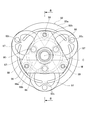
- FIG. 2 is a side view showing the armature 82, the leaf spring 97, and the hub 87 in the electromagnetic clutch 80 of the first embodiment according to the arrow A in FIG. 1
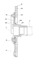
- FIG. 3 is a sectional view taken along the line BB in FIG.
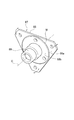
- FIG. 4 is a perspective view showing the hub 87 in FIG.
- the armature 82 is disposed so as to face the end surface (outer surface) of the rotor 81 via a preset gap.
- the armature 82 is substantially circular in a plan view shown in FIG. 2, and has an outer ring portion 82a on the outer side and an inner ring portion 82b on the inner side of the outer ring portion 82a.
- the outer ring portion 82a and the inner ring portion 82b are connected by three connecting portions 82c in the circumferential direction around the axis C.
- the armature 82 is in contact with the end surface of the rotor 81 (see FIG. 1) by the magnetic flux generated by energization of the electromagnetic coil 83, and the rotation of the rotor 81 is transmitted.
- the armature 82 is separated from the end surface of the rotor 81 due to the disappearance of the magnetic flux by the energization stop of the electromagnetic coil 83, and the rotation of the rotor 81 is not transmitted.
- the hub 87 has a cylindrical boss portion 89 centered on the shaft center C, and extends from one end of the boss portion 89 to the outside in the radial direction of the shaft center C. And a flange portion 88.
- the boss portion 89 and the flange portion 88 are integrally formed.
- the boss portion 89 is connected to the rotating shaft 51 by a bolt 16.
- the flange portion 88 has a substantially triangular outline shape in a plan view shown in FIG.
- the flange portion 88 is formed in such a size that the apex that is the longest in the radial direction around the axis C is substantially the same position as the outer shape of the inner ring portion 82 b of the armature 82.
- the flange portion 88 has a portion 88 a (hereinafter referred to as “the outer portion”) that is located on the inner side of the circular boundary M at a predetermined distance from the axis C of the boss portion 89.
- the thick portion 88b is thicker than the thickness of the outer portion 88a.
- the thickness along the axis C of the outer portion 88a is t1
- the thickness along the axis C of the thick portion 88b is t2 (> t1).
- the thick portion 88b is formed in the flange portion 88 over the entire circumference around the axis C.
- the thick part 88 b protrudes in the same direction as the boss part 89 with respect to the flange part 88. Further, the thick part 88 b is formed in contact with the boss part 89.
- the leaf spring 97 is formed in a ring shape. As shown in FIG. 2, three leaf springs 97 are provided in the circumferential direction around the axis C at equal angular intervals. The diameter of the ring of each leaf spring 97 is smaller than the radius of the armature 82. Each leaf spring 97 is coupled to the outer ring portion 82a of the armature 82 by caulking at a portion corresponding to the outer side in the radial direction around the axis C. On the other hand, each leaf spring 97 is coupled and fixed to the flange portion 88 of the hub 87 by a coupling pin 98 at a portion corresponding to the inner side in the radial direction around the axis C.
- the flange portion 88 of the hub 87 is connected to the armature 82 via the leaf spring 97.
- a portion of the flange portion 88 where the leaf spring 97 is fixed by the coupling pin 98 (plate spring fixing portion) is formed in the thick portion 88b. That is, the boundary M is formed on the outer side in the radial direction with respect to the axis C rather than the portion where the leaf spring 97 is fixed.
- the triangular apex of the flange portion 88 is formed in a direction from the axis C toward the portion between the portions where the plate springs 97 are fixed by the coupling pins 98. . That is, each leaf spring 97 is coupled to the flange portion 88 on a line in a direction from the axis C toward the side of the flange portion 88. Therefore, the triangular top portion of the flange portion 88 is on the outer side in the radial direction around the axis C than the portion where the leaf spring 97 is fixed by the coupling pin 98.
- a stopper rubber 99 is fixed to a portion of the outer portion 88a of the flange portion 88 near the top as shown in FIG.
- the stopper rubber 99 is interposed between the flange portion 88 and the inner ring portion 82b of the armature 82 along the axial center C direction, and is in contact with the outer portion 88a of the flange portion 88 and the armature 82. Therefore, the boundary M is formed on the inner side in the radial direction with respect to the axis C than the portion (stopper rubber fixing portion) of the flange portion 88 where the stopper rubber 99 is fixed.
- the armature 82 is attracted to the electromagnetic coil 83 side against the elastic force of the leaf spring 97, whereby the armature 82 contacts the rotor 81 and the rotation of the rotor 81 is caused.
- the rotation transmitted to the armature 82 is transmitted to the rotary shaft 51 via the leaf spring 97 and the hub 87, and the compressor body 60 operates to perform a series of compression operations such as suction, compression and discharge of the refrigerant gas G. .
- the inside of the boundary M is formed into a thick part 88b that is thicker than the thickness of the outer part 88a, and the rigidity of the flange part 88 is formed as the thick part 88b.
- the vibration by the bending of the flange part 88 is suppressed compared with the thing in which the thick part 88b is not formed. Therefore, according to the electromagnetic clutch 80 and the compressor 100 of the present embodiment, it is possible to reduce the level of magnetized sound generated by the vibration of the flange portion 88 without increasing the number of parts such as elastic materials.
- the armature 82 When the electromagnetic coil 83 is not energized, the armature 82 is separated from the rotor 81 by the elastic force of the leaf spring 97, and the operation of the compressor body 60 is stopped. When the armature 82 moves away from the rotor 81, the armature 82 returns to the flange portion 88 side of the hub 87. At this time, since the stopper rubber 99 is interposed between the armature 82 and the flange portion 88, the armature 82 and the flange portion 88 are not in direct contact with each other. Therefore, no sound is generated due to the direct contact between the armature 82 and the flange portion 88.
- FIG. 5 is a graph showing the vibration sensitivity of the flange portion 88 of the electromagnetic clutch 80 of the first embodiment and the electromagnetic clutch of the comparative example in which the thick portion 88b is not formed on the flange portion 88.
- the solid line represents the vibration sensitivity of the electromagnetic clutch 80 of the present embodiment
- the broken line represents the vibration sensitivity of the comparative example.
- the vibration of the flange portion 88 of the electromagnetic clutch 80 of the present embodiment is caused by the displacement of the armature 82 being transmitted through the leaf spring 97 to the portion where the leaf spring 97 is fixed.
- the boundary M of the flange portion 88 is set on the outer side in the radial direction with respect to the axis C rather than the portion where the leaf spring 97 is fixed, so that the leaf spring 97 is fixed.
- the portion becomes the thick portion 88b, and the rigidity of the flange portion 88 is increased.
- a portion fixed to the armature 82 of the flange portion 88 (portion fixed by the coupling pin 98) is formed on the outer side in the radial direction from the boundary portion with the boss portion 89. . Therefore, when the flange portion 88 vibrates due to the displacement of the armature 82, the largest bending stress acts near the boundary portion between the flange portion 88 and the boss portion 89.
- the rigidity of the boundary portion between the flange portion 88 and the boss portion 89 can be further improved.
- the thick portion 88b is formed over the entire circumference around the axis C inside the boundary M formed in a circle. It can be improved over the entire circumference around the axis C.
- the thick portion 88b projects in the same direction with respect to the flange portion 88 in the direction along the boss portion 89 and the axis C, and the leaf spring 97 is fixed to the thick portion 88b. . Accordingly, the gap between the surface of the outer portion 88a facing the armature 82 and the surface of the armature 82 facing the flange portion 88 is wider than that in which the thick portion 88b is not formed.
- the thickness of the stopper rubber 99 sandwiched between the surface of the outer portion 88a facing the armature 82 and the surface of the armature 82 facing the flange portion 88 is reduced. It can be formed thick.
- the flange portion 88 has a substantially triangular outline in plan view in FIG. 2, but the flange portion in the electromagnetic clutch according to the present invention is not limited to this shape, for example, a substantially rectangular shape Or a substantially pentagonal outline. Moreover, the outline shape of the flange part 88 is not limited to a square shape, A circular shape, a star shape, etc. may be sufficient. The same applies to the following embodiments and modifications.
- the leaf spring 97 that couples the armature 82 and the hub 87 is formed in a ring shape.
- the leaf spring in the electromagnetic clutch according to the present invention is not limited to this shape. It may be a shape, a bent shape, or a curved shape. The same applies to the following embodiments and modifications.
- the thick portion 88b is formed over the entire circumference around the axis C, but may be formed only in a part of the range around the axis C. In this case, for example, when formed in a portion in the direction from the axis C toward the top of the flange 88 (the direction toward the portion where the stopper rubber 99 is fixed), the vibration of the top can be effectively suppressed. it can.
- the thick part 88b is formed so as to protrude in the same direction as the boss part 89 with respect to the flange part 88 rather than the outer part 88a.
- the flange portion 88 may be formed so as to protrude in the opposite direction to the boss portion 89.
- the electromagnetic clutch 80 of the present embodiment is formed so that the thick portion 88b is in contact with the boss portion 89, but the electromagnetic clutch according to the present invention is not limited to this form, and the thick portion is separated from the boss portion. It may be formed. In the case where the thick portion is formed away from the boss portion, the thick portion is preferably formed over the entire circumference around the axis of the boss portion.
- FIG. 6 is a side view corresponding to FIG. 2 showing the armature 82, the leaf spring 97, and the hub 187 in the electromagnetic clutch 180 of the second embodiment (Embodiment 2) of the present invention
- FIG. FIG. 8 is a perspective view showing the hub 187 in FIG. 6.
- the illustrated electromagnetic clutch 180 is attached to the housing 10 in the compressor 100 shown in FIG. 1 instead of the electromagnetic clutch 80 of the first embodiment.
- the electromagnetic clutch 180 has the same configuration as the electromagnetic clutch 80 except that a hub 187 is provided instead of the hub 87.
- the hub 187 is formed by integrally forming a flange portion 188 corresponding to the flange portion 88 of the hub 87 and a boss portion 189 that is the same as the boss portion 89.
- the flange portion 188 has a thickness direction of the flange portion 188 (along the axis C) from the surface of the flange portion 188 to the outer peripheral edge corresponding to each of the substantially triangular three sides.
- a rib 90 projecting in the direction) is formed.
- the flange portion 188 is the same as the flange portion 88 except that the rib 90 is formed, and the inner side of the boundary M forms a thick portion 188b that is thicker than the outer portion 188a.
- Each rib 90 is formed in a shape extending along the side. As shown in FIG. 7, each rib 90 protrudes in a direction opposite to the boss 189 with respect to the flange 188.
- the leaf spring 97 is formed in a ring shape. As shown in FIG. 6, three leaf springs 97 are provided in the circumferential direction around the axis C at regular angular intervals. The diameter of the ring of each leaf spring 97 is smaller than the radius of the armature 82.
- the triangular top of the flange portion 188 is formed in a direction from the axis C toward the portion between the portions where the leaf springs 97 are fixed by the coupling pins 98. . That is, each leaf spring 97 is coupled to the flange portion 188 on a line in a direction from the axis C toward the side of the flange portion 188. Therefore, the triangular top portion of the flange portion 188 is on the outer side in the radial direction around the axis C than the portion connected to the armature 82 by the connecting pin 98.
- the rotation of the rotor 81 is not transmitted to the armature 82 because the rotor 81 and the armature 82 are separated when the electromagnetic coil 83 is not energized. . Therefore, the rotary shaft 51 connected to the armature 82 via the leaf spring 97 and the hub 187 does not rotate, and the compressor body 60 does not operate.
- the armature 82 is attracted to the electromagnetic coil 83 side against the elastic force of the leaf spring 97, whereby the armature 82 contacts the rotor 81 and the rotation of the rotor 81 is caused.
- the rotation transmitted to the armature 82 is transmitted to the rotary shaft 51 via the leaf spring 97 and the hub 187, and the compressor body 60 operates to perform a series of compression operations such as suction, compression and discharge of the refrigerant gas G. .
- the rib 90 is formed on the outer peripheral edge of the hub 187 together with the thick portion 188b. Therefore, the rigidity of the flange portion 188 is further improved as compared with the flange portion where the thick portion 188b and the rib 90 are not formed. Thereby, the vibration by the bending of the flange part 188 is suppressed compared with the thing without the thick part 188b and the rib 90. FIG. Therefore, according to the electromagnetic clutch 180 and the compressor 100 of the second embodiment, the level of magnetized sound generated by the vibration of the flange portion 188 can be further reduced without increasing the number of parts such as elastic materials.
- the flange portion 188 of the electromagnetic clutch 180 has a triangular apex formed at a portion radially outward from a portion coupled to the armature 82 by the coupling pin 98, so that the flange portion 188 and the boss portion are formed.
- a large bending stress acts near the center of the triangular side.
- the rib 90 is formed corresponding to the triangular side of the flange portion 188 together with the thick portion 188b. Therefore, the rigidity of the side is also increased, and the flange portion 188 is deformed or vibrated. Can be more effectively suppressed.
- the rib 90 corresponding to the side has a linear shape compared to the case where the flange portion 188 is circular (in this case, the rib 90 is arc-shaped), the length of the rib 90 is shorter than that of the arc. can do. Therefore, an increase in weight due to the formed rib 90 can be suppressed.
- the rib 90 protrudes in the direction opposite to the boss portion 89 with respect to the flange portion 188, and therefore the flange portion 188 of the hub 187 with respect to the existing electromagnetic clutch.
- the difference in thickness between the outer portion 188a and the thick portion 188b is the positional relationship between the outer portion 188a and the thick portion 188b. Just change it. Therefore, labor when applying the present invention by design change can be reduced.
- the electromagnetic clutch 180 of the present embodiment has, for example, a flange by bending the outer peripheral portion of the flange portion 188 in which the rib 90 is not formed in the thickness direction of the flange portion 188 (direction along the axis C). Ribs 90 are formed on the outer peripheral edge of the portion 188. Thereby, compared with what joins the rib 90 by welding etc., the rib 90 can be formed easily.
- the electromagnetic clutch according to the present invention is not limited to the electromagnetic clutch in which the rib is formed by this manufacturing method. That is, the rib may be integrally formed by forging when forming the flange portion, or may be formed by being welded to the flange portion.
- the rib 90 is formed so as to protrude in the direction opposite to the boss portion 189 with respect to the flange portion 188, but the rib 90 is formed with respect to the flange portion 188. It may be formed to protrude in the same direction as 189. However, the rib 90 needs to be formed avoiding the leaf spring 97. According to the electromagnetic clutch 180 configured as described above, even if the rib 90 is formed, the entire length of the electromagnetic clutch 180 along the axis C direction can be suppressed to the same length as that of the existing electromagnetic clutch. it can.
- FIG. 9 is a side view corresponding to FIG. 2 showing the armature 82, the leaf spring 97, and the hub 287 in the electromagnetic clutch 280 of the third embodiment (third embodiment) of the present invention
- FIG. 10 is a DD in FIG.
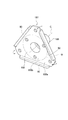
- FIG. 11 is a perspective view showing the hub 287 in FIG. 9.
- the illustrated electromagnetic clutch 280 is attached to the housing 10 in the compressor 100 shown in FIG. 1 instead of the electromagnetic clutch 80 of the first embodiment.
- the electromagnetic clutch 280 has the same configuration as the electromagnetic clutch 80 except that a hub 287 is provided instead of the hub 87 of the electromagnetic clutch 80.
- the hub 287 is formed by integrally forming a flange portion 288 corresponding to the flange portion 88 of the hub 87 and a boss portion 289 that is the same as the boss portion 89.
- the flange portion 288 includes a rib (hereinafter referred to as a joining rib) 288 c that is bridged and joined to the boss portion 89.
- a joining rib hereinafter referred to as a joining rib
- Three joining ribs 288c are formed at equal angular intervals around the axis C.
- the flange portion 288 is formed in a substantially triangular shape having three apexes as in the flange portion 88, and the three joining ribs 288c are on the lines respectively directed from the axis C to the three apexes (as shown in FIG. 11). (Represented by a one-dot chain line).
- Each leaf spring 97 is coupled to the flange portion 288 on a line in a direction from the axis C toward the side of the flange portion 288.
- the three joining ribs 288c are formed in the part between the parts to which the leaf
- the boundary N is an imaginary line with a preset distance from the axis C of the boss portion 89, and the joint portion on the flange portion 288 side of the joining rib 288 c is formed inside the boundary N.
- the rotation of the rotor 81 is not transmitted to the armature 82 because the rotor 81 and the armature 82 are separated when the electromagnetic coil 83 is not energized. . Therefore, the rotary shaft 51 connected to the armature 82 via the leaf spring 97 and the hub 287 does not rotate, and the compressor main body 60 does not operate.
- the armature 82 is attracted to the electromagnetic coil 83 side against the elastic force of the leaf spring 97, whereby the armature 82 contacts the rotor 81 and the rotation of the rotor 81 is caused.
- the rotation transmitted to the armature 82 is transmitted to the rotary shaft 51 via the leaf spring 97 and the hub 287, and the compressor main body 60 operates to perform a series of compression operations such as suction, compression and discharge of the refrigerant gas G. .
- the electromagnetic clutch 280 of the third embodiment is joined with the flange portion 288 and the boss portion 289 being joined.
- 288c increases the rigidity of the flange portion 288 with respect to bending in the thickness direction as compared with the case without the joining rib 288c. Thereby, the vibration by the bending of the flange part 288 is suppressed compared with the thing without the joining rib 288c. Therefore, according to the electromagnetic clutch 280 and the compressor 100 of the third embodiment, the level of magnetized sound generated by the vibration of the flange portion 288 can be further reduced without increasing the number of parts such as elastic materials.
- FIG. 12 is a graph showing the vibration sensitivity of the flange portion 288 of the electromagnetic clutch 280 of the third embodiment and the electromagnetic clutch of the comparative example in which the joining rib 288c is not formed on the flange portion 288.
- the solid line represents the vibration sensitivity of the electromagnetic clutch 280 of the third embodiment
- the broken line represents the vibration sensitivity of the comparative example.
- the joining rib 288c is formed in a portion on a line from the axis C toward the top of the substantially triangular shape of the flange portion 288. Therefore, the electromagnetic clutch 280 can effectively reduce the bending of the triangular portion of the flange portion 288, particularly the top portion.
- the joining rib 288c is formed by the leaf spring 97. It is possible to adopt an arrangement that does not interfere with the portion to be fixed (plate spring fixing portion).
- the compressor 100 of each embodiment mentioned above is a vane rotary type gas compressor
- the gas compressor to which the electromagnetic clutch which concerns on this invention is applied is not limited to a vane rotary type gas compressor. . Therefore, an electromagnetic clutch applied to a gas compressor other than the vane rotary type (swash plate type gas compressor, scroll type gas compressor, etc.) is also an object of the present invention.
Landscapes
- Engineering & Computer Science (AREA)
- General Engineering & Computer Science (AREA)
- Mechanical Engineering (AREA)
- Physics & Mathematics (AREA)
- Electromagnetism (AREA)
- Compressors, Vaccum Pumps And Other Relevant Systems (AREA)
- Compressor (AREA)
Abstract
気体圧縮機用の電磁クラッチにおいて、部品点数を増加させることなく、着磁音を低減する。コンプレッサ(100)用の電磁クラッチ(80)は、磁力によりロータ(81)に断接されるアーマチュア(82)と、アーマチュア(82)に板ばね(97)を介して連結されたフランジ部(88)及び回転軸(51)に連結されるボス部(89)を有するハブ(87)と、を備え、ハブ(87)のフランジ部(88)は、ボス部(89)の軸心(C)から予め設定された距離の境界(M)よりも内側に、境界(M)よりも外側の部分(外側部(88a))の厚さよりも厚い厚肉部(88b)を有している。
Description
本発明は、気体圧縮機用の電磁クラッチ及び気体圧縮機に関する。
空気調和システム(以下、空調システムという。)には、冷媒ガスなどの気体を高圧の圧縮気体に圧縮する気体圧縮機が用いられている。
この気体圧縮機のうち外部から動力を受けて動作するものは、その動力の断接を切り替えるために、電磁クラッチを備えている。
この気体圧縮機のうち外部から動力を受けて動作するものは、その動力の断接を切り替えるために、電磁クラッチを備えている。
電磁クラッチは、プーリと一体的に回転するロータと、電磁コイルと、電磁コイルの通電によって発生した磁束によりロータの外面に接し、電磁コイルの通電停止によって磁束が消失することによりロータの外面から離れるアーマチュアと、板ばねを介してアーマチュアに連結されたフランジ部及び回転軸に連結されたボス部を有するハブと、を備えている。(例えば、特許文献1参照)。
ところで、電磁コイルに通電してアーマチュアがロータに接続されたとき、音(着磁音)が発生する。この音が車室内に侵入すると、乗員に対して異音として聴覚を刺激するものとなる。
そこで、特許文献1においては、板ばねとハブとの間に弾性材を設ける技術が提案されている。この技術によれば、アーマチュアとロータとの接続の際の衝撃を、弾性材の圧縮により緩衝して、音の発生を抑制している。しかし、弾性材の追加は、部品点数と組立工数とがそれぞれ増加するため、製造コストの上昇を招く。
ここで、本発明の発明者は、接続の際に発生した音を詳細に分析したところ、発生した音は、ハブの固有振動モードが深く関与していることが判明した。
そこで、特許文献1においては、板ばねとハブとの間に弾性材を設ける技術が提案されている。この技術によれば、アーマチュアとロータとの接続の際の衝撃を、弾性材の圧縮により緩衝して、音の発生を抑制している。しかし、弾性材の追加は、部品点数と組立工数とがそれぞれ増加するため、製造コストの上昇を招く。
ここで、本発明の発明者は、接続の際に発生した音を詳細に分析したところ、発生した音は、ハブの固有振動モードが深く関与していることが判明した。
本発明は、上述した、着磁音にハブの固有振動モードが深く関与しているとの新たな知見に基づいてなされたものであり、部品点数を増加させることなく、着磁音を低減することができる気体圧縮機用の電磁クラッチ及び気体圧縮機を提供することを目的とする。
本発明の第1は、磁力によりロータに断接されるアーマチュアと、前記アーマチュアに板ばねを介して連結されたフランジ部及び回転軸に連結されたボス部を有するハブと、を備え、前記フランジ部は、前記ボス部の軸心から予め設定された距離の境界よりも内側の少なくとも一部に、前記境界よりも外側の部分の厚さよりも厚い厚肉部を有している、気体圧縮機用の電磁クラッチである。
本発明の第2は、本発明に係る電磁クラッチと、前記電磁クラッチのハブに連結された回転軸を有する圧縮機本体と、を備えた気体圧縮機である。
本発明に係る気体圧縮機用の電磁クラッチ及び気体圧縮機によれば、部品点数を増加させることなく、着磁音を低減することができる。
以下、本発明に係る気体圧縮機用の電磁クラッチ及び気体圧縮機の実施形態について図面を参照して説明する。図1は、本発明に係る気体圧縮機の一例であるベーンロータリ形式のコンプレッサ100の縦断面を示す断面図である。
[実施形態1]
<コンプレッサの構成>
図示のコンプレッサ100は、例えば、冷却媒体の気化熱を利用して冷却を行なう空調システムの一部として構成される。この空調システムの他の構成要素である凝縮器、膨張弁、蒸発器等(いずれも図示を省略する)とともに冷却媒体の循環経路上に設けられている。なお、この空調システムは、例えば、車両(自動車など)の車室内の温度調整を行うための空調装置である。
<コンプレッサの構成>
図示のコンプレッサ100は、例えば、冷却媒体の気化熱を利用して冷却を行なう空調システムの一部として構成される。この空調システムの他の構成要素である凝縮器、膨張弁、蒸発器等(いずれも図示を省略する)とともに冷却媒体の循環経路上に設けられている。なお、この空調システムは、例えば、車両(自動車など)の車室内の温度調整を行うための空調装置である。
コンプレッサ100は、蒸発器から取り入れた気体の冷却媒体としての冷媒ガスGを圧縮し、この圧縮された冷媒ガスGを凝縮器に供給する。凝縮器は圧縮された冷媒ガスGを液化させ、高圧で液状の冷媒として膨張弁に送出する。そして、高圧で液状の冷媒は、膨張弁で低圧化され、蒸発器に送出される。低圧の液状の冷媒は、蒸発器において周囲の空気から吸熱して気化し、気化熱を奪うことで蒸発器の周囲の空気を冷却する。気化して気体となった冷媒ガスGはコンプレッサ100に戻される。
コンプレッサ100は、図1に示すように、一端が開口し他端が閉じた略円筒状の本体ケース11と、この本体ケース11の一端側の開口を塞ぐフロントヘッド12とにより形成されたハウジング10を有している。本体ケース11とフロントヘッド12とは、複数本の六角ボルト等で締結されて、内部に空間を形成している。このハウジング10の内部の空間に、圧縮機本体60と油分離器70とが配置されている。
ハウジング10には、リテーナ(スナップリング)15により、圧縮機本体60の回転軸51に連結された電磁クラッチ80が固定されている。電磁クラッチ80は、本発明に係る気体圧縮機用の電磁クラッチの第1の実施形態(実施形態1)である。
ハウジング10には、リテーナ(スナップリング)15により、圧縮機本体60の回転軸51に連結された電磁クラッチ80が固定されている。電磁クラッチ80は、本発明に係る気体圧縮機用の電磁クラッチの第1の実施形態(実施形態1)である。
フロントヘッド12は、蒸発器から低圧の冷媒ガスGをハウジング10の内部に吸入する吸入ポート12aを有している。本体ケース11は、ハウジング10の内部から高温、高圧の冷媒ガスGを凝縮器に吐出する吐出ポート11aを有している。フロントヘッド12には、回転軸51が通った円筒状のノーズ部12bを有し、ノーズ部12bに続いて、電磁クラッチ80が突き当てられる平面状の座面12cが形成されている。
ハウジング10の内部の空間は、圧縮機本体60によって、吸入ポート12aに通じた吸入室13と、吐出ポート11aに通じた吐出室14とに仕切られている。
圧縮機本体60は、例えばベーンロータリ形式の圧縮機であり、回転軸51の軸心C回りに回転することで、吸入室13を通じて低圧の冷媒ガスGを吸入して高温、高圧に圧縮し、圧縮された高圧の冷媒ガスGを、油分離器70を通じて吐出室14に吐出する。
油分離器70は、通過する冷媒ガスGから冷凍機油Rを分離する。
圧縮機本体60は、例えばベーンロータリ形式の圧縮機であり、回転軸51の軸心C回りに回転することで、吸入室13を通じて低圧の冷媒ガスGを吸入して高温、高圧に圧縮し、圧縮された高圧の冷媒ガスGを、油分離器70を通じて吐出室14に吐出する。
油分離器70は、通過する冷媒ガスGから冷凍機油Rを分離する。
<電磁クラッチの構成>
電磁クラッチ80は、回転軸51への動力の供給の断接を切り替える。電磁クラッチ80は、ロータ81と、電磁コイル83と、コイルハウジング86と、アーマチュア82と、ハブ87と、を備えている。
コイルハウジング86は、内部に電磁コイル83を収容した円環状のコイルケース84と、コイルケース84に接合されて、フロントヘッド12に固定されるフランジプレート85とを有している。
電磁クラッチ80は、回転軸51への動力の供給の断接を切り替える。電磁クラッチ80は、ロータ81と、電磁コイル83と、コイルハウジング86と、アーマチュア82と、ハブ87と、を備えている。
コイルハウジング86は、内部に電磁コイル83を収容した円環状のコイルケース84と、コイルケース84に接合されて、フロントヘッド12に固定されるフランジプレート85とを有している。
フランジプレート85は、コイルケース84が接合された側とは反対の面が、フロントヘッド12に形成された座面12cに突き当てられた状態で、ノーズ部12bに取り付けられるリテーナ15により、フロントヘッド12に固定されている。電磁コイル83及びコイルハウジング86は、ハウジング10に固定されているため動かない。
ロータ81は、コイルケース84を囲むように形成されている。ロータ81は、フロントヘッド12のノーズ部12bに、ラジアルボールベアリング17を介して結合されている。ロータ81は、コンプレッサ100が搭載される車両からの動力を受けるプーリと一体的に、軸心C回りに回転する。
図2は、図1の矢視Aによる、実施形態1の電磁クラッチ80におけるアーマチュア82、板ばね97及びハブ87を示す側面図、図3は、図2におけるB-B線に沿った断面を示す断面図、図4は、図2におけるハブ87を示す斜視図である。
アーマチュア82は、図1に示すように、ロータ81の端面(外面)と予め設定された隙間を介して対向して配置されている。アーマチュア82は、図2に示す平面視で略円形であり、外側の外輪部分82aと、外輪部分82aよりも内側の内輪部分82bとを有している。
アーマチュア82は、図1に示すように、ロータ81の端面(外面)と予め設定された隙間を介して対向して配置されている。アーマチュア82は、図2に示す平面視で略円形であり、外側の外輪部分82aと、外輪部分82aよりも内側の内輪部分82bとを有している。
外輪部分82aと内輪部分82bとは、軸心C回りの周方向の3か所の繋ぎ部82cで繋がっている。
アーマチュア82は、電磁コイル83の通電によって発生した磁束によりロータ81(図1参照)の端面に接し、ロータ81の回転が伝達される。一方、アーマチュア82は、電磁コイル83の通電停止によって磁束が消失することによりロータ81の端面から離れ、ロータ81の回転が伝達されなくなる。
アーマチュア82は、電磁コイル83の通電によって発生した磁束によりロータ81(図1参照)の端面に接し、ロータ81の回転が伝達される。一方、アーマチュア82は、電磁コイル83の通電停止によって磁束が消失することによりロータ81の端面から離れ、ロータ81の回転が伝達されなくなる。
ハブ87は、図2,3,4に示すように、軸心Cを中心とする円筒状のボス部89と、ボス部89の一方の端部から軸心Cの半径方向の外側に延びたフランジ部88とを有している。ボス部89とフランジ部88とは一体に形成されている。
ボス部89は、図1に示すように、ボルト16により回転軸51に連結されている。
フランジ部88は、図2に示す平面視で、略三角形の輪郭形状を有している。フランジ部88は、軸心C回りの半径方向に最も長い頂部がアーマチュア82の内輪部分82bの外形と略同じ位置となるような大きさで形成されている。
ボス部89は、図1に示すように、ボルト16により回転軸51に連結されている。
フランジ部88は、図2に示す平面視で、略三角形の輪郭形状を有している。フランジ部88は、軸心C回りの半径方向に最も長い頂部がアーマチュア82の内輪部分82bの外形と略同じ位置となるような大きさで形成されている。
フランジ部88は、図2,3,4に示すように、ボス部89の軸心Cから予め設定された距離の円形の境界Mよりも内側に、境界Mよりも外側の部分88a(以下、外側部88aという。)の厚さよりも厚い厚肉部88bを有している。ここで、図3に示すように、外側部88aの軸心Cに沿った厚さをt1としたとき、厚肉部88bの軸心Cに沿った厚さはt2(>t1)である。
厚肉部88bは、軸心C回りの全周に亘ってフランジ部88に形成されている。厚肉部88bは、フランジ部88に対して、ボス部89と同じ向きに突出している。また、厚肉部88bは、ボス部89に接して形成されている。
厚肉部88bは、軸心C回りの全周に亘ってフランジ部88に形成されている。厚肉部88bは、フランジ部88に対して、ボス部89と同じ向きに突出している。また、厚肉部88bは、ボス部89に接して形成されている。
板ばね97は、リング状に形成されている。板ばね97は、図2に示すように、軸心C回りの周方向に、等角度間隔で3つ設けられている。各板ばね97のリングの直径はアーマチュア82の半径よりも小さい。
各板ばね97は、軸心C回りの半径方向の外側に対応する部分において、カシメにより、アーマチュア82の外輪部分82aに結合されている。一方、各板ばね97は、軸心C回りの半径方向の内側に対応する部分において、結合ピン98により、ハブ87のフランジ部88に結合されて固定されている。
各板ばね97は、軸心C回りの半径方向の外側に対応する部分において、カシメにより、アーマチュア82の外輪部分82aに結合されている。一方、各板ばね97は、軸心C回りの半径方向の内側に対応する部分において、結合ピン98により、ハブ87のフランジ部88に結合されて固定されている。
したがって、ハブ87のフランジ部88は、板ばね97を介してアーマチュア82に連結されている。
フランジ部88の、結合ピン98により板ばね97が固定された部分(板ばね固定部)は、厚肉部88bに形成されている。すなわち、境界Mが、板ばね97が固定された部分よりも軸心Cに対する半径方向の外側に形成されている。
フランジ部88の、結合ピン98により板ばね97が固定された部分(板ばね固定部)は、厚肉部88bに形成されている。すなわち、境界Mが、板ばね97が固定された部分よりも軸心Cに対する半径方向の外側に形成されている。
フランジ部88の三角形の頂部は、図2に示すように、軸心Cから、各板ばね97がそれぞれ結合ピン98により固定された部分同士の各間の部分に向いた方向に形成されている。つまり、各板ばね97は、軸心Cからフランジ部88の辺に向かう方向の線上において、フランジ部88と結合されている。したがって、フランジ部88の三角形の頂部は、結合ピン98で板ばね97が固定された部分よりも、軸心C回りの半径方向に沿って外側となる。
フランジ部88の外側部88aのうち頂部の付近の部分には、図3に示すように、ストッパゴム99が固定されている。ストッパゴム99は、フランジ部88とアーマチュア82の内輪部分82bとの、軸心C方向に沿った間に介在し、フランジ部88の外側部88a及びアーマチュア82に接している。
したがって、境界Mは、フランジ部88のストッパゴム99が固定された部分(ストッパゴム固定部)よりも軸心Cに対する半径方向の内側に形成されている。
したがって、境界Mは、フランジ部88のストッパゴム99が固定された部分(ストッパゴム固定部)よりも軸心Cに対する半径方向の内側に形成されている。
<電磁クラッチの作用>
以上のように構成された実施形態の電磁クラッチ80によると、電磁コイル83に通電されていないときは、ロータ81とアーマチュア82とが離れているため、ロータ81の回転は、アーマチュア82に伝達されない。したがって、アーマチュア82と、板ばね97及びハブ87を介して連結された回転軸51は回転せず、圧縮機本体60は動作しない。
以上のように構成された実施形態の電磁クラッチ80によると、電磁コイル83に通電されていないときは、ロータ81とアーマチュア82とが離れているため、ロータ81の回転は、アーマチュア82に伝達されない。したがって、アーマチュア82と、板ばね97及びハブ87を介して連結された回転軸51は回転せず、圧縮機本体60は動作しない。
一方、電磁コイル83に通電されると、アーマチュア82が、板ばね97の弾性力に抗して電磁コイル83の側に吸引され、これにより、アーマチュア82がロータ81に接し、ロータ81の回転が、アーマチュア82に伝達される。アーマチュア82に伝達された回転は、板ばね97及びハブ87を介して回転軸51に伝達され、圧縮機本体60が動作して冷媒ガスGの吸入、圧縮及び吐出という一連の圧縮動作が行われる。
ここで、アーマチュア82がロータ81に接したとき、音(着磁音)が発生する。
本発明者の分析によると、この着磁音は、ハブ87の固有振動モードが深く関与していることが判明した。
すなわち、具体的には、アーマチュア82がロータ81に接する際に、アーマチュア82に対して軸心C方向の、ロータ81とは反対の側に配置されているハブ87のフランジ部88(特に、頂部に近い部分)が、図4の矢印で示すように、軸心Cに沿った方向に撓む振動が発生することが判明した。そして、この振動によって生じる音は、例えば4000[Hz]付近の周波数であり、ハブ87の固有振動モードによる音であった。
本発明者の分析によると、この着磁音は、ハブ87の固有振動モードが深く関与していることが判明した。
すなわち、具体的には、アーマチュア82がロータ81に接する際に、アーマチュア82に対して軸心C方向の、ロータ81とは反対の側に配置されているハブ87のフランジ部88(特に、頂部に近い部分)が、図4の矢印で示すように、軸心Cに沿った方向に撓む振動が発生することが判明した。そして、この振動によって生じる音は、例えば4000[Hz]付近の周波数であり、ハブ87の固有振動モードによる音であった。
そこで、本実施形態の電磁クラッチ80は、境界Mよりも内側を、外側部88aの厚さよりも厚い厚肉部88bに形成して、フランジ部88の剛性を、厚肉部88bの形成されていないフランジ部に比べて向上させている。
これにより、フランジ部88の撓みによる振動が、厚肉部88bの形成されていないものに比べて抑制される。したがって、本実施形態の電磁クラッチ80及びコンプレッサ100によれば、弾性材等部品の数を増加させることなく、フランジ部88の振動により発生する着磁音のレベルを低減することができる。
これにより、フランジ部88の撓みによる振動が、厚肉部88bの形成されていないものに比べて抑制される。したがって、本実施形態の電磁クラッチ80及びコンプレッサ100によれば、弾性材等部品の数を増加させることなく、フランジ部88の振動により発生する着磁音のレベルを低減することができる。
なお、電磁コイル83への通電が無くなると、アーマチュア82は板ばね97の弾性力によりロータ81から離れ、圧縮機本体60の動作は停止する。アーマチュア82がロータ81から離れたとき、アーマチュア82はハブ87のフランジ部88の側に戻る。このとき、アーマチュア82とフランジ部88との間には、ストッパゴム99が介在するため、アーマチュア82とフランジ部88とが直接接触することはない。したがって、アーマチュア82とフランジ部88とが直接接触することによる音は発生しない。
<解析例>
図5は、実施形態1の電磁クラッチ80と、フランジ部88に厚肉部88bが形成されていない比較例の電磁クラッチとの、フランジ部88の振動感度を示したグラフである。
なお、グラフにおいて、実線は本実施形態の電磁クラッチ80の振動感度であり、破線は比較例の振動感度である。
図5に示したように、本実施形態の電磁クラッチ80は、周波数4000[Hz]付近の振動感度が、比較例に比べて大幅に低減されている。これにより、本実施形態の電磁クラッチ80は比較例に比べて、着磁音を低減することが実証された。
図5は、実施形態1の電磁クラッチ80と、フランジ部88に厚肉部88bが形成されていない比較例の電磁クラッチとの、フランジ部88の振動感度を示したグラフである。
なお、グラフにおいて、実線は本実施形態の電磁クラッチ80の振動感度であり、破線は比較例の振動感度である。
図5に示したように、本実施形態の電磁クラッチ80は、周波数4000[Hz]付近の振動感度が、比較例に比べて大幅に低減されている。これにより、本実施形態の電磁クラッチ80は比較例に比べて、着磁音を低減することが実証された。
本実施形態の電磁クラッチ80のフランジ部88の振動は、アーマチュア82の変位が、板ばね97を介して、板ばね97が固定された部分に伝わることで生じる。本実施形態の電磁クラッチ80は、フランジ部88の境界Mが、板ばね97が固定された部分よりも軸心Cに対する半径方向の外側に設定されていることにより、板ばね97が固定された部分が厚肉部88bとなって、フランジ部88の剛性が高められる。一方、フランジ部88の全体の板厚を厚くすると重量が増加するが、ストッパゴム99が固定された部分よりも内側に境界Mが設定されていることで、板厚を増大させる範囲を少なくすることができ、板厚の増大に伴う重量の増加を抑えることができる。
本実施形態の電磁クラッチ80は、フランジ部88のアーマチュア82に固定された部分(結合ピン98で固定された部分)が、ボス部89との境界部よりも半径方向の外側に形成されている。したがって、フランジ部88がアーマチュア82の変位により振動したとき、このフランジ部88とボス部89との境界部付近に最も大きな曲げ応力が作用する。
ここで、本実施形態の電磁クラッチ80は、厚肉部88bがボス部89に接しているため、フランジ部88とボス部89との境界部の剛性を一層向上させることができる。
ここで、本実施形態の電磁クラッチ80は、厚肉部88bがボス部89に接しているため、フランジ部88とボス部89との境界部の剛性を一層向上させることができる。
また、本実施形態の電磁クラッチ80は、厚肉部88bが、円に形成された境界Mの内側の、軸心C回りの全周に亘って形成されているため、フランジ部88の剛性を、軸心C回りの全周に亘って向上させることができる。
本実施形態の電磁クラッチ80は、厚肉部88bがフランジ部88に対してボス部89と軸心Cに沿った方向に関して同じ向きに突出し、厚肉部88bに板ばね97が固定されている。したがって、外側部88aにおけるアーマチュア82に向いた面と、アーマチュア82におけるフランジ部88に向いた面との間の隙間が、厚肉部88bが形成されていないものに比べて広くなる。
本実施形態の電磁クラッチ80は、厚肉部88bがフランジ部88に対してボス部89と軸心Cに沿った方向に関して同じ向きに突出し、厚肉部88bに板ばね97が固定されている。したがって、外側部88aにおけるアーマチュア82に向いた面と、アーマチュア82におけるフランジ部88に向いた面との間の隙間が、厚肉部88bが形成されていないものに比べて広くなる。
この結果、外側部88aにおけるアーマチュア82に向いた面と、アーマチュア82におけるフランジ部88に向いた面との間に挟まれるストッパゴム99の厚さ(軸心Cに沿った方向に関する厚さ)を厚く形成することができる。これにより、電磁コイル83による磁力が消失してアーマチュア82がロータ81から離れた際に、アーマチュア82がフランジ部88の側に戻るときの弾性エネルギを、厚く形成されたストッパゴム99で、より多く吸収することができる。
<変形例>
本実施形態の電磁クラッチ80は、フランジ部88が、図2の平面視の輪郭が略三角形であるが、本発明に係る電磁クラッチにおけるフランジ部は、この形状に限定されず、例えば、略四角形や略五角形の輪郭形状を有するものであってもよい。
また、フランジ部88の輪郭形状は、角形状に限定されず、円形状や星形状等であってもよい。以下の、実施形態、変形例においても同様である。
本実施形態の電磁クラッチ80は、フランジ部88が、図2の平面視の輪郭が略三角形であるが、本発明に係る電磁クラッチにおけるフランジ部は、この形状に限定されず、例えば、略四角形や略五角形の輪郭形状を有するものであってもよい。
また、フランジ部88の輪郭形状は、角形状に限定されず、円形状や星形状等であってもよい。以下の、実施形態、変形例においても同様である。
本実施形態の電磁クラッチ80は、アーマチュア82とハブ87とを結合する板ばね97がリング状に形成されているが、本発明に係る電磁クラッチにおける板ばねは、この形状に限定されず、矩形状であってもよいし、屈曲した形状や曲線状に曲がった形状であってもよい。以下の、実施形態、変形例においても同様である。
本実施形態の電磁クラッチ80は、厚肉部88bが、軸心C回りの全周に亘って形成されているが、軸心C回りの一部の範囲にのみ形成されていてもよい。この場合、例えば、軸心Cからフランジ部88の頂部に向かう方向(ストッパゴム99が固定された部分に向かう方向)の部分に形成されていると、頂部の振動を効果的に抑制することができる。
本実施形態の電磁クラッチ80は、厚肉部88bが、外側部88aよりもフランジ部88に対してボス部89と同じ向きに突出して形成されているが、厚肉部88bが、外側部88aよりもフランジ部88に対してボス部89と反対の向きに突出して形成されていてもよい。
本実施形態の電磁クラッチ80は、厚肉部88bがボス部89に接して形成されているが、本発明に係る電磁クラッチは、この形態に限定されず、厚肉部がボス部から離れて形成されていてもよい。なお、厚肉部がボス部から離れて形成されているものでは、厚肉部が、ボス部の軸心回りの全周に亘って形成されていることが好ましい。
[実施形態2]
図6は、本発明の第2の実施形態(実施形態2)の電磁クラッチ180におけるアーマチュア82、板ばね97及びハブ187を示す図2相当の側面図、図7は、図6におけるC-C線に沿った断面を示す断面図、図8は、図6におけるハブ187を示す斜視図である。
図示の電磁クラッチ180は、図1に示したコンプレッサ100において、実施形態1の電磁クラッチ80に代えてハウジング10に取り付けられている。
図6は、本発明の第2の実施形態(実施形態2)の電磁クラッチ180におけるアーマチュア82、板ばね97及びハブ187を示す図2相当の側面図、図7は、図6におけるC-C線に沿った断面を示す断面図、図8は、図6におけるハブ187を示す斜視図である。
図示の電磁クラッチ180は、図1に示したコンプレッサ100において、実施形態1の電磁クラッチ80に代えてハウジング10に取り付けられている。
<電磁クラッチの構成>
電磁クラッチ180は、電磁クラッチ80に対して、ハブ87に代えてハブ187が備えられている以外は同じ構成である。ハブ187は、ハブ87のフランジ部88に相当するフランジ部188と、ボス部89と同じボス部189とが一体に形成されたものである。
フランジ部188は、図6,8に示すように、その略三角形状の3つの辺にそれぞれ対応する外周縁に、フランジ部188の表面からフランジ部188の厚さ方向(軸心Cに沿った方向)に突出したリブ90が形成されている。
電磁クラッチ180は、電磁クラッチ80に対して、ハブ87に代えてハブ187が備えられている以外は同じ構成である。ハブ187は、ハブ87のフランジ部88に相当するフランジ部188と、ボス部89と同じボス部189とが一体に形成されたものである。
フランジ部188は、図6,8に示すように、その略三角形状の3つの辺にそれぞれ対応する外周縁に、フランジ部188の表面からフランジ部188の厚さ方向(軸心Cに沿った方向)に突出したリブ90が形成されている。
フランジ部188は、リブ90が形成されている以外は、フランジ部88と同じであり、境界Mの内側が外側部188aよりも板厚の厚い厚肉部188bを形成している。各リブ90は、辺に沿って延びた形状に形成されている。
各リブ90は、図7に示すように、フランジ部188に対して、ボス部189とは反対の向きに突出している。
板ばね97は、リング状に形成されている。板ばね97は、図6に示すように、軸心C回りの周方向に、等角度間隔で3つ設けられている。各板ばね97のリングの直径はアーマチュア82の半径よりも小さい。
各リブ90は、図7に示すように、フランジ部188に対して、ボス部189とは反対の向きに突出している。
板ばね97は、リング状に形成されている。板ばね97は、図6に示すように、軸心C回りの周方向に、等角度間隔で3つ設けられている。各板ばね97のリングの直径はアーマチュア82の半径よりも小さい。
フランジ部188の三角形の頂部は、図6に示すように、軸心Cから、各板ばね97がそれぞれ結合ピン98により固定された部分同士の各間の部分に向いた方向に形成されている。つまり、各板ばね97は、軸心Cからフランジ部188の辺に向かう方向の線上において、フランジ部188と結合されている。したがって、フランジ部188の三角形の頂部は、アーマチュア82と結合ピン98で結合されている部分よりも、軸心C回りの半径方向に沿って外側となる。
<電磁クラッチの作用>
以上のように構成された実施形態の電磁クラッチ180によると、電磁コイル83に通電されていないときは、ロータ81とアーマチュア82とが離れているため、ロータ81の回転は、アーマチュア82に伝達されない。したがって、アーマチュア82と、板ばね97及びハブ187を介して連結された回転軸51は回転せず、圧縮機本体60は動作しない。
以上のように構成された実施形態の電磁クラッチ180によると、電磁コイル83に通電されていないときは、ロータ81とアーマチュア82とが離れているため、ロータ81の回転は、アーマチュア82に伝達されない。したがって、アーマチュア82と、板ばね97及びハブ187を介して連結された回転軸51は回転せず、圧縮機本体60は動作しない。
一方、電磁コイル83に通電されると、アーマチュア82が、板ばね97の弾性力に抗して電磁コイル83の側に吸引され、これにより、アーマチュア82がロータ81に接し、ロータ81の回転が、アーマチュア82に伝達される。アーマチュア82に伝達された回転は、板ばね97及びハブ187を介して回転軸51に伝達され、圧縮機本体60が動作して冷媒ガスGの吸入、圧縮及び吐出という一連の圧縮動作が行われる。
ここで、アーマチュア82がロータ81に接したとき、音(着磁音)が発生するが、実施形態2の電磁クラッチ180は、厚肉部188bとともにハブ187の外周縁にリブ90が形成されているため、フランジ部188の剛性が、厚肉部188b及びリブ90の形成されていないフランジ部に比べて一層向上している。
これにより、フランジ部188の撓みによる振動が、厚肉部188b及びリブ90の無いものに比べて抑制される。したがって、実施形態2の電磁クラッチ180及びコンプレッサ100によれば、弾性材等部品の数を増加させることなく、フランジ部188の振動により発生する着磁音のレベルを一層低減させることができる。
これにより、フランジ部188の撓みによる振動が、厚肉部188b及びリブ90の無いものに比べて抑制される。したがって、実施形態2の電磁クラッチ180及びコンプレッサ100によれば、弾性材等部品の数を増加させることなく、フランジ部188の振動により発生する着磁音のレベルを一層低減させることができる。
本実施形態の電磁クラッチ180のフランジ部188は、結合ピン98によりアーマチュア82に結合された部分よりも半径方向の外側の部分に、三角形の頂部が形成されているため、フランジ部188とボス部189との境界部を中心としてフランジ部188が振動したとき、三角形の辺の中央部付近に大きな曲げ応力が作用する。
本実施形態の電磁クラッチ180は、厚肉部188bとともに、フランジ部188の三角形の辺に対応してリブ90が形成されているため、辺の剛性をも高めて、フランジ部188の変形つまり振動を一層有効に抑制することができる。
しかも、フランジ部188が円形であるもの(この場合、リブ90は円弧状)に比べて、辺に対応するリブ90が直線状となるため、円弧の場合と比べてリブ90の長さを短くすることができる。したがって、形成されたリブ90による重量増加を抑制することができる。
しかも、フランジ部188が円形であるもの(この場合、リブ90は円弧状)に比べて、辺に対応するリブ90が直線状となるため、円弧の場合と比べてリブ90の長さを短くすることができる。したがって、形成されたリブ90による重量増加を抑制することができる。
また、本実施形態の電磁クラッチ180は、リブ90が、フランジ部188に対して、ボス部89とは反対の向きに突出しているため、既存の電磁クラッチに対して、ハブ187のフランジ部188とアーマチュア82等との位置関係(特に、ボス部189に連結される回転軸51の軸心Cに沿った方向についての位置関係)を、外側部188aと厚肉部188bとの厚さの差分だけ変更するだけでよい。したがって、設計変更により本発明を適用する場合の労力を軽減することができる。
なお、厚肉部188bをボス部189と反対の向きに突出させたものでは、既存の電磁クラッチに対して、ハブ187のフランジ部188とアーマチュア82等との位置関係(特に、ボス部189に連結される回転軸51の軸心Cに沿った方向についての位置関係)を、まったく変更する必要がない。
なお、厚肉部188bをボス部189と反対の向きに突出させたものでは、既存の電磁クラッチに対して、ハブ187のフランジ部188とアーマチュア82等との位置関係(特に、ボス部189に連結される回転軸51の軸心Cに沿った方向についての位置関係)を、まったく変更する必要がない。
<変形例>
なお、本実施形態の電磁クラッチ180は、例えば、リブ90が形成されていないフランジ部188の外周部を、フランジ部188の厚さ方向(軸心Cに沿った方向)に折り曲げることにより、フランジ部188の外周縁にリブ90が形成されている。これにより、リブ90を溶接等で接合するものに比べて、リブ90を容易に形成することができる。
ただし、本発明に係る電磁クラッチは、この製造方法でリブが形成された電磁クラッチに限定されない。すなわち、リブは、フランジ部を形成する際に鍛造により一体に形成してもよいし、フランジ部に溶接で付加して形成してもよい。
なお、本実施形態の電磁クラッチ180は、例えば、リブ90が形成されていないフランジ部188の外周部を、フランジ部188の厚さ方向(軸心Cに沿った方向)に折り曲げることにより、フランジ部188の外周縁にリブ90が形成されている。これにより、リブ90を溶接等で接合するものに比べて、リブ90を容易に形成することができる。
ただし、本発明に係る電磁クラッチは、この製造方法でリブが形成された電磁クラッチに限定されない。すなわち、リブは、フランジ部を形成する際に鍛造により一体に形成してもよいし、フランジ部に溶接で付加して形成してもよい。
本実施形態の電磁クラッチ180は、リブ90が、フランジ部188に対して、ボス部189とは反対の向きに突出して形成されているが、リブ90は、フランジ部188に対して、ボス部189と同じ向きに突出して形成されていてもよい。ただし、リブ90は、板ばね97を避けて形成する必要がある。
このように構成された電磁クラッチ180によれば、リブ90が形成されていても、軸心C方向に沿った電磁クラッチ180全体の長さを、既存の電磁クラッチと同じ長さに抑えることができる。
このように構成された電磁クラッチ180によれば、リブ90が形成されていても、軸心C方向に沿った電磁クラッチ180全体の長さを、既存の電磁クラッチと同じ長さに抑えることができる。
[実施形態3]
図9は、本発明の第3の実施形態(実施形態3)の電磁クラッチ280におけるアーマチュア82、板ばね97及びハブ287を示す図2相当の側面図、図10は、図9におけるD-D線に沿った断面を示す断面図、図11は、図9におけるハブ287を示す斜視図である。
図示の電磁クラッチ280は、図1に示したコンプレッサ100において、実施形態1の電磁クラッチ80に代えてハウジング10に取り付けられている。
図9は、本発明の第3の実施形態(実施形態3)の電磁クラッチ280におけるアーマチュア82、板ばね97及びハブ287を示す図2相当の側面図、図10は、図9におけるD-D線に沿った断面を示す断面図、図11は、図9におけるハブ287を示す斜視図である。
図示の電磁クラッチ280は、図1に示したコンプレッサ100において、実施形態1の電磁クラッチ80に代えてハウジング10に取り付けられている。
<電磁クラッチの構成>
電磁クラッチ280は、電磁クラッチ80のハブ87に代えてハブ287が備えられている以外は、電磁クラッチ80と同じ構成である。ハブ287は、ハブ87のフランジ部88に相当するフランジ部288と、ボス部89と同じボス部289とが一体に形成されたものである。
電磁クラッチ280は、電磁クラッチ80のハブ87に代えてハブ287が備えられている以外は、電磁クラッチ80と同じ構成である。ハブ287は、ハブ87のフランジ部88に相当するフランジ部288と、ボス部89と同じボス部289とが一体に形成されたものである。
フランジ部288は、図9,10,11に示すように、ボス部89に架け渡されて接合されたリブ(以下、接合リブという。)288cを備えている。接合リブ288cは、軸心C回りの等角度間隔で3つ形成されている。
フランジ部288は、フランジ部88と同じく3つの頂部を有する略三角形に形成され、3つの接合リブ288cは、図11に示すように、軸心Cから3つの頂部にそれぞれ向かう線上(図中の一点鎖線で表す)の部分に形成されている。
フランジ部288は、フランジ部88と同じく3つの頂部を有する略三角形に形成され、3つの接合リブ288cは、図11に示すように、軸心Cから3つの頂部にそれぞれ向かう線上(図中の一点鎖線で表す)の部分に形成されている。
板ばね97は、フランジ部288の、ボス部289の軸心Cを中心とした周方向に沿って等角度間隔で3つ設けられている。各板ばね97は、軸心Cからフランジ部288の辺に向かう方向の線上において、フランジ部288と結合されている。
これにより、3つの接合リブ288cは、図9に示すように、板ばね97がそれぞれ固定された部分同士の間の部分に形成されている。
接合リブ288cが形成されたフランジ部288は、接合リブ288cが形成されていない、境界Nよりも外側のフランジ部288に比べて、厚さが厚いため、接合リブ288cは厚肉部の一例となっている。なお、境界Nは、ボス部89の軸心Cから予め設定された距離の仮想線であり、接合リブ288cのフランジ部288側での結合部は境界Nよりも内側に形成されている。
これにより、3つの接合リブ288cは、図9に示すように、板ばね97がそれぞれ固定された部分同士の間の部分に形成されている。
接合リブ288cが形成されたフランジ部288は、接合リブ288cが形成されていない、境界Nよりも外側のフランジ部288に比べて、厚さが厚いため、接合リブ288cは厚肉部の一例となっている。なお、境界Nは、ボス部89の軸心Cから予め設定された距離の仮想線であり、接合リブ288cのフランジ部288側での結合部は境界Nよりも内側に形成されている。
<電磁クラッチの作用>
以上のように構成された実施形態の電磁クラッチ280によると、電磁コイル83に通電されていないときは、ロータ81とアーマチュア82とが離れているため、ロータ81の回転は、アーマチュア82に伝達されない。したがって、アーマチュア82と、板ばね97及びハブ287を介して連結された回転軸51は回転せず、圧縮機本体60は動作しない。
以上のように構成された実施形態の電磁クラッチ280によると、電磁コイル83に通電されていないときは、ロータ81とアーマチュア82とが離れているため、ロータ81の回転は、アーマチュア82に伝達されない。したがって、アーマチュア82と、板ばね97及びハブ287を介して連結された回転軸51は回転せず、圧縮機本体60は動作しない。
一方、電磁コイル83に通電されると、アーマチュア82が、板ばね97の弾性力に抗して電磁コイル83の側に吸引され、これにより、アーマチュア82がロータ81に接し、ロータ81の回転が、アーマチュア82に伝達される。アーマチュア82に伝達された回転は、板ばね97及びハブ287を介して回転軸51に伝達され、圧縮機本体60が動作して冷媒ガスGの吸入、圧縮及び吐出という一連の圧縮動作が行われる。
ここで、アーマチュア82がロータ81に接したとき、音(着磁音)が発生するが、実施形態3の電磁クラッチ280は、フランジ部288とボス部289とを架け渡して接合された接合リブ288cが、接合リブ288cのないものに比べて、フランジ部288の厚さ方向の曲げに対する剛性を増大させている。
これにより、フランジ部288の撓みによる振動が、接合リブ288cの無いものに比べて抑制される。したがって、実施形態3の電磁クラッチ280及びコンプレッサ100によれば、弾性材等部品の数を増加させることなく、フランジ部288の振動により発生する着磁音のレベルを一層低減させることができる。
これにより、フランジ部288の撓みによる振動が、接合リブ288cの無いものに比べて抑制される。したがって、実施形態3の電磁クラッチ280及びコンプレッサ100によれば、弾性材等部品の数を増加させることなく、フランジ部288の振動により発生する着磁音のレベルを一層低減させることができる。
<解析例>
図12は、実施形態3の電磁クラッチ280と、フランジ部288に接合リブ288cが形成されていない比較例の電磁クラッチとの、フランジ部288の振動感度を示したグラフである。なお、グラフにおいて、実線は本実施形態3の電磁クラッチ280の振動感度であり、破線は比較例の振動感度である。
図12に示したように、本実施形態3の電磁クラッチ280は、周波数4000[Hz]付近の振動感度が、比較例に比べて大幅に低減されている。これにより、本実施形態3の電磁クラッチ280は比較例に比べて、着磁音を低減することが実証された。
図12は、実施形態3の電磁クラッチ280と、フランジ部288に接合リブ288cが形成されていない比較例の電磁クラッチとの、フランジ部288の振動感度を示したグラフである。なお、グラフにおいて、実線は本実施形態3の電磁クラッチ280の振動感度であり、破線は比較例の振動感度である。
図12に示したように、本実施形態3の電磁クラッチ280は、周波数4000[Hz]付近の振動感度が、比較例に比べて大幅に低減されている。これにより、本実施形態3の電磁クラッチ280は比較例に比べて、着磁音を低減することが実証された。
本実施形態3の電磁クラッチ280のフランジ部288は、接合リブ288cが、軸心Cからフランジ部288の略三角形の頂部に向かう線上の部分に形成されている。したがって、電磁クラッチ280は、フランジ部288の三角形の、特に頂部の撓みを効果的に低減することができる。
本実施形態3の電磁クラッチ280は、3つの接合リブ288cが、フランジ部288の、板ばね97がそれぞれ固定された部分同士の間の部分に形成されているため、接合リブ288cが板ばね97の固定される部分(板ばね固定部)に干渉しない配置を採ることができる。
上述した各実施形態のコンプレッサ100は、ベーンロータリ形式の気体圧縮機であるが、本発明に係る電磁クラッチが適用される気体圧縮機は、ベーンロータリ形式の気体圧縮機に限定されるものではない。したがって、ベーンロータリ形式以外の形式の気体圧縮機(斜板式の気体圧縮機、スクロール形式の気体圧縮機等)に適用される電磁クラッチも本発明の対象となる。
本出願は、2015年5月22日に日本国特許庁に出願された特願2015-104741及び2015年6月3日に日本国特許庁に出願された特願2015-112842に基づいて優先権を主張し、その全ての開示は完全に本明細書で参照により組み込まれる。
Claims (13)
- 磁力によりロータに断接されるアーマチュアと、
前記アーマチュアに板ばねを介して連結されたフランジ部及び回転軸に連結されたボス部を有するハブと、を備え、
前記フランジ部は、前記ボス部の軸心から予め設定された距離の境界よりも内側の少なくとも一部に、前記境界よりも外側の部分の厚さよりも厚い厚肉部を有している、気体圧縮機用の電磁クラッチ。 - 前記フランジ部は、前記板ばねが固定された板ばね固定部と、前記アーマチュアとの間に介在するストッパゴムが固定されたストッパゴム固定部とを有し、
前記境界は、前記軸心を中心とする半径方向の、前記板ばね固定部と前記ストッパゴム固定部との間に形成されている、請求項1に記載の気体圧縮機用の電磁クラッチ。 - 前記厚肉部は、前記フランジ部に対して、前記ボス部と同じ向きに突出している請求項2に記載の気体圧縮機用の電磁クラッチ。
- 前記境界は、前記軸心を中心とした円であり、
前記厚肉部は、前記境界よりも内側の、前記軸心回りの全周に亘って形成されている請求項1から3のうちいずれか1項に記載の気体圧縮機用の電磁クラッチ。 - 前記厚肉部は、前記フランジ部と前記ボス部との間に架け渡された接合リブである請求項1から3のうちいずれか1項に記載の気体圧縮機用の電磁クラッチ。
- 前記フランジ部は、3つ以上の頂部を有する角形に形成され、
前記接合リブは、前記軸心から前記頂部に向かう線上に形成されている、請求項5に記載の気体圧縮機用の電磁クラッチ。 - 前記板ばねが、前記フランジ部の、前記ボス部の軸心を中心とした周方向に沿って複数設けられ、
前記接合リブは、前記板ばねがそれぞれ固定された部分同士の間の部分に形成されている請求項5又は6に記載の気体圧縮機用の電磁クラッチ。 - 前記厚肉部は、前記ボス部に接している請求項1から7のうちいずれか1項に記載の気体圧縮機用の電磁クラッチ。
- 前記フランジ部の外周縁に、前記フランジ部の厚さ方向に突出したリブが形成されている、請求項1から8のうちいずれか1項に記載の気体圧縮機用の電磁クラッチ。
- 前記板ばねが、前記フランジ部の、前記ボス部の軸心を中心とした周方向に沿って複数設けられ、
前記フランジ部は、前記軸心から、前記板ばねがそれぞれ固定された部分同士の各間の部分に向いた方向に頂部を有する角形に形成され、
前記リブは、前記フランジ部の前記角形の辺に沿って形成されている、請求項9に記載の気体圧縮機用の電磁クラッチ。 - 前記リブは、前記フランジ部に対して、前記ボス部とは反対の向きに突出している請求項9又は10に記載の気体圧縮機用の電磁クラッチ。
- 前記リブは、前記フランジ部に対して、前記ボス部と同じ向きに突出している請求項9又は10に記載の気体圧縮機用の電磁クラッチ。
- 請求項1から12のうちいずれか1項に記載の電磁クラッチと、
前記ハブに連結された回転軸を有する圧縮機本体と、を備えた気体圧縮機。
Applications Claiming Priority (4)
| Application Number | Priority Date | Filing Date | Title |
|---|---|---|---|
| JP2015104741A JP6570313B2 (ja) | 2015-05-22 | 2015-05-22 | 気体圧縮機用の電磁クラッチ及び気体圧縮機 |
| JP2015-104741 | 2015-05-22 | ||
| JP2015-112842 | 2015-06-03 | ||
| JP2015112842A JP2016223600A (ja) | 2015-06-03 | 2015-06-03 | 気体圧縮機用の電磁クラッチ及び気体圧縮機 |
Publications (1)
| Publication Number | Publication Date |
|---|---|
| WO2016189973A1 true WO2016189973A1 (ja) | 2016-12-01 |
Family
ID=57392683
Family Applications (1)
| Application Number | Title | Priority Date | Filing Date |
|---|---|---|---|
| PCT/JP2016/061145 Ceased WO2016189973A1 (ja) | 2015-05-22 | 2016-04-05 | 気体圧縮機用の電磁クラッチ及び気体圧縮機 |
Country Status (1)
| Country | Link |
|---|---|
| WO (1) | WO2016189973A1 (ja) |
Cited By (2)
| Publication number | Priority date | Publication date | Assignee | Title |
|---|---|---|---|---|
| WO2019105586A3 (en) * | 2017-11-29 | 2019-09-06 | Eaton Intelligent Power Limited | Spring-applied clutch and supercharger system |
| CN113459722A (zh) * | 2021-07-07 | 2021-10-01 | 南京航空航天大学 | 可切换运动形态并变换外形的非充气车轮及其变换方法 |
Citations (6)
| Publication number | Priority date | Publication date | Assignee | Title |
|---|---|---|---|---|
| JPS5054753A (ja) * | 1973-09-17 | 1975-05-14 | ||
| JPH0241726U (ja) * | 1988-09-13 | 1990-03-22 | ||
| JPH0271130U (ja) * | 1988-11-21 | 1990-05-30 | ||
| JPH08135684A (ja) * | 1994-11-10 | 1996-05-31 | Ogura Clutch Co Ltd | 電磁連結装置のアーマチュア組立体 |
| JP2014209022A (ja) * | 2013-03-29 | 2014-11-06 | サンデン株式会社 | 電磁クラッチ及び電磁クラッチの製造方法 |
| JP2014218164A (ja) * | 2013-05-08 | 2014-11-20 | 株式会社ジェイテクト | ジョイントカバー |
-
2016
- 2016-04-05 WO PCT/JP2016/061145 patent/WO2016189973A1/ja not_active Ceased
Patent Citations (6)
| Publication number | Priority date | Publication date | Assignee | Title |
|---|---|---|---|---|
| JPS5054753A (ja) * | 1973-09-17 | 1975-05-14 | ||
| JPH0241726U (ja) * | 1988-09-13 | 1990-03-22 | ||
| JPH0271130U (ja) * | 1988-11-21 | 1990-05-30 | ||
| JPH08135684A (ja) * | 1994-11-10 | 1996-05-31 | Ogura Clutch Co Ltd | 電磁連結装置のアーマチュア組立体 |
| JP2014209022A (ja) * | 2013-03-29 | 2014-11-06 | サンデン株式会社 | 電磁クラッチ及び電磁クラッチの製造方法 |
| JP2014218164A (ja) * | 2013-05-08 | 2014-11-20 | 株式会社ジェイテクト | ジョイントカバー |
Cited By (2)
| Publication number | Priority date | Publication date | Assignee | Title |
|---|---|---|---|---|
| WO2019105586A3 (en) * | 2017-11-29 | 2019-09-06 | Eaton Intelligent Power Limited | Spring-applied clutch and supercharger system |
| CN113459722A (zh) * | 2021-07-07 | 2021-10-01 | 南京航空航天大学 | 可切换运动形态并变换外形的非充气车轮及其变换方法 |
Similar Documents
| Publication | Publication Date | Title |
|---|---|---|
| US9366254B2 (en) | Vehicular scroll compressor having housing arrangements for improved vibration isolation | |
| US9488165B2 (en) | Reciprocating compressor | |
| US10626931B2 (en) | Electromagnetic clutch mechanism | |
| JP4713293B2 (ja) | 圧縮機 | |
| US7311188B2 (en) | Electromagnetic clutch | |
| WO2016189973A1 (ja) | 気体圧縮機用の電磁クラッチ及び気体圧縮機 | |
| JP2016223600A (ja) | 気体圧縮機用の電磁クラッチ及び気体圧縮機 | |
| JP6570313B2 (ja) | 気体圧縮機用の電磁クラッチ及び気体圧縮機 | |
| JP2015158156A (ja) | スクロール型圧縮機 | |
| US10851842B2 (en) | Power transmission device | |
| JP6927140B2 (ja) | 電磁クラッチ | |
| WO2016189972A1 (ja) | 気体圧縮機用の電磁クラッチ、気体圧縮機及び気体圧縮機用の電磁クラッチの製造方法 | |
| JP6373051B2 (ja) | 電磁クラッチ及び気体圧縮機 | |
| JP6521717B2 (ja) | 気体圧縮機用の電磁クラッチ及び気体圧縮機 | |
| US10941818B2 (en) | Clutch and compressor comprising same | |
| JP2013204446A (ja) | 圧縮機 | |
| US10253773B2 (en) | Attachment structure for compressor | |
| JP6747399B2 (ja) | 動力伝達装置 | |
| KR102899730B1 (ko) | 클러치 및 이를 포함하는 압축기 | |
| CN112912639B (zh) | 离合器和包括离合器的压缩机 | |
| JP2008095566A (ja) | 気体圧縮機 | |
| JP6311189B2 (ja) | 電磁クラッチ及び気体圧縮機 | |
| JP2018096524A (ja) | 動力伝達装置 | |
| JP2015132275A (ja) | 電磁クラッチ及び気体圧縮機 | |
| JP2017219092A (ja) | 動力伝達装置 |
Legal Events
| Date | Code | Title | Description |
|---|---|---|---|
| 121 | Ep: the epo has been informed by wipo that ep was designated in this application |
Ref document number: 16799681 Country of ref document: EP Kind code of ref document: A1 |
|
| NENP | Non-entry into the national phase |
Ref country code: DE |
|
| 122 | Ep: pct application non-entry in european phase |
Ref document number: 16799681 Country of ref document: EP Kind code of ref document: A1 |