WO2016188400A1 - 轴承 - Google Patents
轴承 Download PDFInfo
- Publication number
- WO2016188400A1 WO2016188400A1 PCT/CN2016/083113 CN2016083113W WO2016188400A1 WO 2016188400 A1 WO2016188400 A1 WO 2016188400A1 CN 2016083113 W CN2016083113 W CN 2016083113W WO 2016188400 A1 WO2016188400 A1 WO 2016188400A1
- Authority
- WO
- WIPO (PCT)
- Prior art keywords
- ring
- inner ring
- bearing
- groove
- outer ring
- Prior art date
Links
Images


Classifications
-
- F—MECHANICAL ENGINEERING; LIGHTING; HEATING; WEAPONS; BLASTING
- F16—ENGINEERING ELEMENTS AND UNITS; GENERAL MEASURES FOR PRODUCING AND MAINTAINING EFFECTIVE FUNCTIONING OF MACHINES OR INSTALLATIONS; THERMAL INSULATION IN GENERAL
- F16C—SHAFTS; FLEXIBLE SHAFTS; ELEMENTS OR CRANKSHAFT MECHANISMS; ROTARY BODIES OTHER THAN GEARING ELEMENTS; BEARINGS
- F16C33/00—Parts of bearings; Special methods for making bearings or parts thereof
- F16C33/72—Sealings
- F16C33/76—Sealings of ball or roller bearings
- F16C33/78—Sealings of ball or roller bearings with a diaphragm, disc, or ring, with or without resilient members
- F16C33/784—Sealings of ball or roller bearings with a diaphragm, disc, or ring, with or without resilient members mounted to a groove in the inner surface of the outer race and extending toward the inner race
- F16C33/7843—Sealings of ball or roller bearings with a diaphragm, disc, or ring, with or without resilient members mounted to a groove in the inner surface of the outer race and extending toward the inner race with a single annular sealing disc
- F16C33/7846—Sealings of ball or roller bearings with a diaphragm, disc, or ring, with or without resilient members mounted to a groove in the inner surface of the outer race and extending toward the inner race with a single annular sealing disc with a gap between the annular disc and the inner race
- F16C33/785—Bearing shields made of sheet metal
-
- F—MECHANICAL ENGINEERING; LIGHTING; HEATING; WEAPONS; BLASTING
- F16—ENGINEERING ELEMENTS AND UNITS; GENERAL MEASURES FOR PRODUCING AND MAINTAINING EFFECTIVE FUNCTIONING OF MACHINES OR INSTALLATIONS; THERMAL INSULATION IN GENERAL
- F16C—SHAFTS; FLEXIBLE SHAFTS; ELEMENTS OR CRANKSHAFT MECHANISMS; ROTARY BODIES OTHER THAN GEARING ELEMENTS; BEARINGS
- F16C33/00—Parts of bearings; Special methods for making bearings or parts thereof
- F16C33/30—Parts of ball or roller bearings
- F16C33/58—Raceways; Race rings
- F16C33/583—Details of specific parts of races
-
- F—MECHANICAL ENGINEERING; LIGHTING; HEATING; WEAPONS; BLASTING
- F16—ENGINEERING ELEMENTS AND UNITS; GENERAL MEASURES FOR PRODUCING AND MAINTAINING EFFECTIVE FUNCTIONING OF MACHINES OR INSTALLATIONS; THERMAL INSULATION IN GENERAL
- F16C—SHAFTS; FLEXIBLE SHAFTS; ELEMENTS OR CRANKSHAFT MECHANISMS; ROTARY BODIES OTHER THAN GEARING ELEMENTS; BEARINGS
- F16C33/00—Parts of bearings; Special methods for making bearings or parts thereof
- F16C33/72—Sealings
- F16C33/76—Sealings of ball or roller bearings
- F16C33/78—Sealings of ball or roller bearings with a diaphragm, disc, or ring, with or without resilient members
- F16C33/7816—Details of the sealing or parts thereof, e.g. geometry, material
- F16C33/782—Details of the sealing or parts thereof, e.g. geometry, material of the sealing region
-
- F—MECHANICAL ENGINEERING; LIGHTING; HEATING; WEAPONS; BLASTING
- F16—ENGINEERING ELEMENTS AND UNITS; GENERAL MEASURES FOR PRODUCING AND MAINTAINING EFFECTIVE FUNCTIONING OF MACHINES OR INSTALLATIONS; THERMAL INSULATION IN GENERAL
- F16C—SHAFTS; FLEXIBLE SHAFTS; ELEMENTS OR CRANKSHAFT MECHANISMS; ROTARY BODIES OTHER THAN GEARING ELEMENTS; BEARINGS
- F16C33/00—Parts of bearings; Special methods for making bearings or parts thereof
- F16C33/72—Sealings
- F16C33/76—Sealings of ball or roller bearings
- F16C33/78—Sealings of ball or roller bearings with a diaphragm, disc, or ring, with or without resilient members
- F16C33/784—Sealings of ball or roller bearings with a diaphragm, disc, or ring, with or without resilient members mounted to a groove in the inner surface of the outer race and extending toward the inner race
- F16C33/7859—Sealings of ball or roller bearings with a diaphragm, disc, or ring, with or without resilient members mounted to a groove in the inner surface of the outer race and extending toward the inner race with a further sealing element
- F16C33/7863—Sealings of ball or roller bearings with a diaphragm, disc, or ring, with or without resilient members mounted to a groove in the inner surface of the outer race and extending toward the inner race with a further sealing element mounted to the inner race, e.g. a flinger to use centrifugal effect
-
- F—MECHANICAL ENGINEERING; LIGHTING; HEATING; WEAPONS; BLASTING
- F16—ENGINEERING ELEMENTS AND UNITS; GENERAL MEASURES FOR PRODUCING AND MAINTAINING EFFECTIVE FUNCTIONING OF MACHINES OR INSTALLATIONS; THERMAL INSULATION IN GENERAL
- F16C—SHAFTS; FLEXIBLE SHAFTS; ELEMENTS OR CRANKSHAFT MECHANISMS; ROTARY BODIES OTHER THAN GEARING ELEMENTS; BEARINGS
- F16C33/00—Parts of bearings; Special methods for making bearings or parts thereof
- F16C33/72—Sealings
- F16C33/76—Sealings of ball or roller bearings
- F16C33/80—Labyrinth sealings
-
- F—MECHANICAL ENGINEERING; LIGHTING; HEATING; WEAPONS; BLASTING
- F16—ENGINEERING ELEMENTS AND UNITS; GENERAL MEASURES FOR PRODUCING AND MAINTAINING EFFECTIVE FUNCTIONING OF MACHINES OR INSTALLATIONS; THERMAL INSULATION IN GENERAL
- F16C—SHAFTS; FLEXIBLE SHAFTS; ELEMENTS OR CRANKSHAFT MECHANISMS; ROTARY BODIES OTHER THAN GEARING ELEMENTS; BEARINGS
- F16C19/00—Bearings with rolling contact, for exclusively rotary movement
- F16C19/02—Bearings with rolling contact, for exclusively rotary movement with bearing balls essentially of the same size in one or more circular rows
- F16C19/04—Bearings with rolling contact, for exclusively rotary movement with bearing balls essentially of the same size in one or more circular rows for radial load mainly
- F16C19/06—Bearings with rolling contact, for exclusively rotary movement with bearing balls essentially of the same size in one or more circular rows for radial load mainly with a single row or balls
-
- F—MECHANICAL ENGINEERING; LIGHTING; HEATING; WEAPONS; BLASTING
- F16—ENGINEERING ELEMENTS AND UNITS; GENERAL MEASURES FOR PRODUCING AND MAINTAINING EFFECTIVE FUNCTIONING OF MACHINES OR INSTALLATIONS; THERMAL INSULATION IN GENERAL
- F16C—SHAFTS; FLEXIBLE SHAFTS; ELEMENTS OR CRANKSHAFT MECHANISMS; ROTARY BODIES OTHER THAN GEARING ELEMENTS; BEARINGS
- F16C2300/00—Application independent of particular apparatuses
- F16C2300/02—General use or purpose, i.e. no use, purpose, special adaptation or modification indicated or a wide variety of uses mentioned
Definitions
- This application relates to the field of machinery, and in particular to a bearing.
- Bearings are an important part of contemporary mechanical equipment. They have been widely used in various occasions where rotation is required. Their main function is to support the mechanical rotating body, reduce the friction coefficient during its movement, and ensure its rotation accuracy. Good lubrication and sealing are the necessary conditions and key to ensure the normal use of the bearing. There are many kinds of lubricating oil for the bearing, such as oil bath, splash, oil mist lubrication, etc. However, the bearings installed and used in some small spaces cannot be used. Lubrication method generally only uses grease or lubricant, and adopts a sealing structure to prevent the lubricant or grease in the bearing from overflowing. The sealing structure can also prevent external dust from entering the bearing interior.
- Bearing seals can be divided into self-contained seals and external seals.
- the so-called self-contained bearing is a bearing with a sealing performance device, such as a bearing with a dust cover, a sealing ring and the like.
- the sealing space is small, the installation and disassembly are convenient, and the cost is relatively low.
- the so-called bearing-incorporated sealing performance device is a sealing device having various properties manufactured inside a mounting end cap or the like.
- FIG. 1 A prior art bearing seal structure design is shown in FIG. 1.
- the bearing 1 includes an outer ring 2, an inner ring 3, balls 4, and a dust cover 5, and the dust cover 5 is designed to be non-contact type to achieve lower
- the frictional force is provided on the outer ring 2 for mounting the dust cover 5.
- the outer surface of the inner ring 3 is provided with a corresponding assembly gap, which makes the bearing sealing structure only prevent Larger dust or contaminated particles enter the inside of the bearing, but they are not able to withstand the dust and pollution particles.
- bearing grease on the one hand It is easy to accumulate in the fitting groove between the radially inner end of the dust cover 5 and the inner side of the inner ring 3, and fine dust and particles enter the bearing from the assembly gap between the dust cover 5 and the outer side of the inner ring 3. At the same time, the grease which should be sealed in the bearing 1 also overflows from the assembly gap, especially when the bearing is applied in a harsh environment with poor environment, dust, impurities and mud, and the prior art is more difficult to meet the demand.
- the problem solved by the present invention is to provide a bearing to solve the technical problem that the bearing sealing effect is not good.
- the present invention provides a bearing including an outer ring, an inner ring, a rolling body between the outer ring and the inner ring, and two dust covers, wherein the two dust covers are A radial space is defined between the outer ring and the inner ring, the rolling body is located in the radial space, one of the outer ring and the inner ring has a press-fit groove, and the other has an end face at the axial end face groove;
- the dust cover includes a body, a mounting mating portion, and a clearance mating portion that is axially convex with respect to the body;
- the mounting mating portion is in interference fit with the press fitting groove, and the gap matching portion protrudes into the end groove and is matched with the end groove.
- the clearance mating portion is a flange extending axially from the body toward the side where the rolling elements are located.
- the cross-sectional shape of the clearance mating portion is substantially "[" type, lateral "U” type or "V” type.
- the clearance fit portion includes a plurality of continuous bends or bends.
- a radially outer side of the end face groove forms a radial shoulder
- a radial inner side of the end face groove forms a radial direction a shoulder, the outer end of the radial shoulder being recessed relative to the axial end face of the inner or outer ring.
- the dust cover as a whole does not exceed the axial end surface of the outer ring and the axial end surface of the inner ring in the axial direction.
- the clearance fit portion of the dust cover has a corresponding configuration to achieve a clearance fit with the end groove of the inner ring or the outer ring.
- the clearance mating portion of the dust cover presents a complete annular shape extending in the axial direction, or a non-complete annular shape; or the dustproof cover includes a plurality of discontinuous clearance mating portions on the inner circumference and/or the outer circumference,
- the plurality of discontinuous clearance mating portions have the same radius, different radii, or appear as the same or different involute segments that overlap or do not overlap in the circumferential direction.
- the inner ring and the outer ring are provided with a press fitting groove and a face groove at the same time, and the inner ring and the press fitting groove on the outer ring do not overlap in the circumferential direction.
- the bearing further includes an oil slinger sleeved on an outer circumference of the inner ring, the oil slinger ring including an axial ring portion extending in the axial direction and abutting the outer circumference of the inner ring, and the axial ring A radial ring portion that is connected and extends in a radial direction, and the oil slinger is disposed in a manner that the radial ring portion is adjacent to the dust cover.
- the dust cover has a clearance fit with the end groove provided in the inner ring or the outer ring, and the assembly gap is designed as a labyrinth type.
- the tortuous path provided by the assembly gap complicates the entry of external contaminants into the grease or the overflow path of the grease, which not only effectively prevents foreign foreign particles from entering the bearing, but also effectively prevents the grease used for lubrication in the bearing from overflowing from the assembly gap. , to ensure a good sealing effect.
- Figure 1 is a schematic view of a prior art bearing structure
- FIG. 2 is a schematic structural view of a bearing embodiment 1 of the present application.
- FIG. 3 is a partial structural schematic view showing the dust cover of the area A in FIG. 2 and the inner ring;
- Figure 4 is a partial perspective structural view of the sealing cover member in Embodiment 1;
- Figure 5 is a schematic structural view of a bearing embodiment 2 of the present application.
- Figure 6 is a partial structural view showing the dust cover of the area B in Figure 5 mated with the inner ring;
- Figure 7 is a schematic structural view of a bearing embodiment 1 of the present application.
- Figure 8 is a partial structural view showing the dust cover of the C area of Figure 7 mated with the inner ring;
- Fig. 9 is a partial perspective structural view showing the sealing cover member of the third embodiment.
- An embodiment of the present invention provides a bearing, as shown in FIG. 1, specifically, the bearing is a deep groove ball bearing, and the bearing 100 includes a coaxially disposed outer ring 10, an inner ring 20, and a collar 10 and a seat 20 Between the rolling bodies 30 and the two dust caps 40, the two dust caps 40 define a radial space between the outer ring 10 and the inner ring 20, and the rolling bodies 30 are in this embodiment Balls, the rolling bodies are located in a radial space defined by the two dust caps 40, and the outer ring 10 and the inner ring 20 are provided with raceways for rolling of the rolling bodies 30 on the sides of the radial spaces facing each other, ie, The ring 10 is provided with an annular raceway on the radially inner side, and the inner ring 20 is provided with an annular raceway on the radially outer side.
- the rolling of the rolling body 30 ensures relatively free rotation of the outer ring 10 and the inner ring 20, in order to keep the rolling body 30 rolling.
- the mutual positional relationship in the process and the relative stability of the position in the bearing also includes a cage 50 for holding the rolling bodies 30 in the radial space described above.
- the two dust caps 40 are opposite in structure, are substantially annular, and are made of a metal material, such as low carbon steel.
- the dust cover 40 includes an annular body 41 located on the body 41. a peripheral fitting portion 42 and a clearance fitting portion 43 located on an inner circumference of the body 41.
- the body 41 has a sheet-like ring shape, and the mounting fitting portion 42 has a curl shape, and the gap fitting portion 43 is axially convex with respect to the body.
- the structure is out, and the axial convex direction of the clearance fitting portion 43 is opposite to the winding direction of the mounting engagement portion 42 in the axial direction.
- the clearance fitting portion 43 is located on the body. 41 axial end of the radial end Bend.
- the outer ring 10 is symmetrical about the axis of rotation of the bearing, the radially inner side of the outer ring 10 forms an outer ring shoulder 11 on both sides of the raceway, and the outer ring shoulder 11 is disposed adjacent to the outer ring 10 to provide a press fit groove 12, A circumferential shoulder 13 projecting radially inward is formed on the outer side of the press fitting groove 12.
- the inner ring 20 is also symmetrical about the axis of rotation of the bearing, and the axial end face of the inner ring 20 is provided with an end face groove 22.
- the end face groove 22 extends in the axial direction and assumes a complete annular shape, and at the end face The radially outer side of the groove 22 forms a radial shoulder 21, and the outer end of the radial shoulder 21 is recessed with respect to the axial end face of the inner ring 20.
- the two dustproof caps 40 are press-fitted into the press fitting groove 12 of the outer ring 10 and the end face groove 22 of the inner ring 20 in a state in which the crimping direction of the fitting portion 42 is directed toward the outer side of the bearing, and accordingly, the clearance fitting portion
- the axial projection of the 43 is toward the inner side of the bearing.
- the portion 42 abuts against the radially inner side of the circumferential shoulder 13 of the outer ring 10, and the mounting engagement portion 42 has an interference fit with the press fitting groove 12, but there is a gap between the groove bottoms of the press fitting groove 12, which can be used for accommodating lubrication.
- the gap matching portion 43 of the dust cover 40 protrudes into the end surface groove 22 of the inner ring 20 in a non-interference manner, and is matched with the end surface groove 22 of the inner ring 20, and the dustproof cover 40
- the axial direction of the outer ring 10 and the axial end face 24 of the inner ring 20 are not exceeded in the axial direction as a whole, thereby reducing space occupation or causing unnecessary friction to other components.
- the clearance fit of the inner ring 20 and the dust cover 40 and the convex and concave structure of the end face groove 22 and the radial shoulder 21 of the inner ring 20 and the clearance fit portion 43 of the dust cover 40 are used.
- the axially protruding structure forms a labyrinth gap between the inner ring 20 and the dust cover 40 as indicated by a broken line in the figure, and the labyrinth gap can prevent the lubricant or grease inside the bearing from overflowing and external dust or The entry of contaminants to achieve an effective sealing effect.
- the bending direction of the clearance fitting portion 43 is not strictly axial, as long as the dust cover 40 is pressed into the gap fit.
- the portion 43 can protrude into the end surface groove 22 of the inner ring 20 on the inner side in the axial direction without interference, and a labyrinth path having at least three bends can be formed between the dust cover 40 and the inner ring 20.
- the bending direction, the bending shape, the structure, and the like of the clearance fitting portion 43 determine the structure of the radial shoulder 21 and the end groove 22 of the inner ring 20.
- the radial shoulder 21 is also changed to a trapezoidal shape.
- the gap matching portion 43 can also be realized by bending, and the contour of the corresponding annular shoulder can also be realized by an arc shape.
- the bearing 200 includes the outer ring 10, the inner ring 20, the roller 30, the dust cover 40 and the retainer 50, which are identical in structure to the first embodiment. Also included are two slinger rings 60 (Flinger).
- the oil slinger 60 is made of a metal material, such as low carbon steel, and has a cross-sectional shape of substantially "L" shape, including an axial ring portion 61 and a radial ring portion 62, and the slinger ring 60 is press-fitted therein.
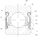
- the bearing 300 includes the outer ring 10 , the roller 30 , the retainer 50 , and the oil slinger 60 of the same structure as the second embodiment, and the dust cover 340 and the inner portion thereof.
- the ring 320 is different from the dust cover 40 and the inner ring 20 in the second embodiment.
- the mounting fitting portion 42 of the dust cover 40 of the second embodiment has the same structure, but the cross-sectional shape of the clearance fitting portion 343 is substantially "[" type, and the opening faces the outer side of the inner ring 320, and correspondingly, the end groove of the inner ring 320
- the groove direction and configuration of the 322 are consistent with the gap matching portion 343, and there is a certain assembly gap therebetween.
- the labyrinth path formed between the inner ring 320, the oil slinger 60 and the dust cover 340 is as follows. The dotted line in Fig. 8 is shown.
- the shape of the mating surface of the gap matching portion 343 and the inner ring 320 is the same.
- the cross-sectional shape of the gap matching portion 343 may be a horizontal "U” shape or a "V” shape, and the like.
- the opening faces the outer side of the inner ring 320.
- the "[", "U” or “V” type branch or both branches near the radially outer side of the inner ring are radially oriented.
- the outer or inner radial direction is inclined, and the clearance fit portion 343 and the inner ring 320 can achieve a non-interference clearance fit as long as the dust cover is pressed.
- the gap matching portion 343 may have a plurality of continuous bending or bending, and correspondingly, a plurality of continuous bending or bending is provided with the bottom surface of the inner ring 320 to match the clearance portion. 343 performs an effective clearance fit to form a good sealing effect. In the labyrinth path, the smaller the angle between adjacent bends or the smaller the radius of the arc, the better the sealing effect.
- the dustproof cover 40, 340 adopts a press fit to achieve an interference fit with the outer ring 10, and at the same time, can achieve a clearance fit with the inner ring 20, 320 without interference, and the cooperation relationship can be applied to the bearing.
- the gap fit of the dust cover 40, 340 of the bearing can be changed.
- the portion is located on the radially outer circumference, and the mounting and fitting portion is located on the radially inner circumference.
- the outer ring 10 is provided with the end surface groove
- the inner ring 20, 320 is provided with the press fitting groove to realize the dust cover 40, 340 and the outer ring 10.
- the end ring groove needs to be machined on the outer ring end face, and the dust cover needs to be fixed on the inner ring.
- the oil ring can be sleeved on the inner circumference of the outer ring.
- the radially inner side of the end face groove forms a radial shoulder, and the outer end of the radial shoulder is recessed with respect to the axial end face of the outer ring.
- the clearance matching portion of the dust cover is formed as a complete annular shape extending in the axial direction, and it is understood that the clearance between the dust cover and the inner ring or the outer ring of the end groove is achieved.
- the gap-engaging portion of the dust cover may be non-completely annular, and may also include a plurality of discontinuous clearance mating portions on the inner circumference and/or the outer circumference, and the plurality of discontinuous clearance mating portions may have The same radius may also have different radii, or the same or different involute segments, and the plurality of clearance mating portions may overlap or not overlap in the circumferential direction, corresponding to the clearance matching portion of the dust cover, the inner ring Or the end face groove of the outer ring has a corresponding configuration for achieving a clearance fit.
- the inner ring and the outer ring can be provided with the press fitting groove and the end face groove at the same time, but the press fitting groove on the inner ring and the outer ring do not overlap in the circumferential direction.
- the dust cover of the protective cover forms a clearance fit with the end groove provided on the inner ring or the outer ring, and the assembly gap is designed to be a labyrinth type.
- the tortuous path provided by the assembly gap complicates the entry of external contaminants into the grease or the overflow path of the grease, which not only effectively prevents foreign foreign particles from entering the bearing, but also effectively prevents the grease used for lubrication in the bearing from overflowing from the assembly gap. , to ensure a good sealing effect, which in turn can improve the high reliability and service life of the bearing.
Abstract
一种轴承(100,200,300),该轴承(100,200,300)包括外圈(10)、内圈(20,320)、位于外圈(10)和内圈(20,320)之间的滚动体(30),以及两个防尘盖(40,340),所述两个防尘盖(40,340)在所述外圈(10)和内圈(20,320)之间界定一径向空间,所述滚动体(30)位于所述径向空间中,所述外圈(10)和内圈(20,320)中的一个具有压装配合槽(12),另一个具有位于轴向端面的端面槽(22,322);所述防尘盖(40,340)包括本体(41),安装配合部(42,342)以及相对于所述本体(41)呈轴向凸出结构的间隙配合部(43,343);所述安装配合部(42,342)与所述压装配合槽(12)过盈配合,所述间隙配合部(43,343)凸伸入所述端面槽(22,322)并与端面槽(22,322)间隙配合。该轴承实现了良好的密封效果。
Description
本申请要求于2015年5月26日提交中国专利局、申请号为201510276397.1、发明名称为“轴承”的中国专利申请的优先权,其全部内容通过引用结合在本申请中。
本申请涉及机械领域,尤其是一种轴承。
轴承是当代机械设备中的一种重要零部件,已被广泛应用到需要旋转的各种场合,其主要功能是支撑机械旋转体,降低其运动过程中的摩擦系数,并保证其回转精度。良好的润滑和密封是保证轴承能正常使用的必要条件和关键,轴承的润滑油很多种,如油浴、飞溅、油雾润滑等,但在一些狭小空间里安装、使用的轴承却不能使用上述润滑方式,一般只能采用润滑脂或润滑剂,并采用密封结构阻止轴承内的润滑剂或润滑脂外溢,该密封结构还可以防止外界粉尘进入轴承内部。
轴承的密封可分为自带密封和外加密封两类。所谓轴承自带密封就是轴承本身具有密封性能装置,如轴承带防尘盖、密封圈等。这种密封占用空间很小,安装拆卸方便,造价也比较低。所谓轴承外加密封性能装置,就是在安装端盖等内部制造成具有各种性能的密封装置。
一种现有技术的轴承密封结构设计如图1所示,该轴承1包括外圈2、内圈3、滚珠4以及防尘盖5,该防尘盖5设计成非接触型以实现较低的摩擦力,外圈2上设置用于安装防尘盖5的安装槽,为了便于防尘盖5的安装,内圈3的外侧表面设置对应的装配间隙,这使得该轴承密封结构仅能防止较大的灰尘或污染颗粒进入轴承内部,但对较小的灰尘和污染颗粒却无能为力,原因如下,一方面轴承润滑脂
容易堆积在防尘盖5的径向内端与内圈3内侧之间的装配槽中,而细微的灰尘和颗粒会从防尘盖5与内圈3外侧之间的装配间隙中进入轴承,同时本应被密封在轴承1中的润滑脂也会从该装配间隙中溢出,尤其在轴承应用于环境差、有灰尘、杂质和泥浆的恶劣环境中时,现有技术更难以满足需求。
发明内容
本发明解决的问题是提供一种轴承,以解决轴承密封效果不佳的技术问题。
为解决上述问题,本发明提供一种轴承,该轴承包括外圈、内圈、位于外圈和内圈之间的滚动体,以及两个防尘盖,所述两个防尘盖在所述外圈和内圈之间界定一径向空间,所述滚动体位于所述径向空间中,所述外圈和内圈中的一个具有压装配合槽,另一个具有位于轴向端面的端面槽;
所述防尘盖包括本体,安装配合部以及相对于所述本体呈轴向凸出结构的间隙配合部;
所述安装配合部与所述压装配合槽过盈配合,所述间隙配合部凸伸入所述端面槽并与端面槽间隙配合。
进一步地,所述间隙配合部为从所述本体向滚动体所在侧沿轴向延伸的折边。
可选地,所述间隙配合部的横截面形状大致呈“〔”型、横向的“U”型或“V”型。
进一步地,所述间隙配合部包括多个连续的弯曲或弯折。
优选地,所述端面槽位于所述内圈时,所述端面槽的径向外侧形成径向凸肩,所述端面槽位于所述外圈时,所述端面槽的径向内侧形成径向凸肩,所述径向凸肩的外侧末端相对于所在内圈或外圈的轴向端面凹入。
进一步地,所述防尘盖整体在轴向上不会超出外圈的轴向端面以及内圈的轴向端面。
优选地,所述防尘盖的间隙配合部与所述内圈或外圈的端面槽具有实现间隙配合的对应构型。
进一步地,防尘盖的间隙配合部呈现为沿轴向延伸的完整环形,或非完整环形;或所述防尘盖包括在内周和/或外周的多个不连续的间隙配合部,该多个不连续的间隙配合部具有相同的半径、不同半径,或呈现为相同或不同的呈渐开线段,该多个间隙配合部在周向上重叠或不重叠。
优选地,所述内圈和外圈同时设置压装配合槽和端面槽,且所述内圈与所述外圈上的压装配合槽在周向上不重叠。
进一步地,所述轴承还包括套设在内圈外周的甩油环,所述甩油环包括沿轴向延伸并贴合在所述内圈外周的轴向环部以及与所述轴向环部连接且沿径向延伸的径向环部,且所述甩油环以径向环部靠近所述防尘盖的方式布置。
本申请相对于现有技术,防尘盖与设置在内圈或外圈的端面槽之间形成间隙配合,且该装配间隙被设计成迷宫型。利用装配间隙提供的曲折路径,使得外部污染物进入或润滑脂的溢出路径复杂化,不仅可以有效防止外界杂质粒子进入到轴承内部,还可以有效防止轴承内用于润滑的润滑脂从装配间隙溢出,保证了良好的密封效果。
图1为现有技术的轴承结构示意图;
图2为本申请轴承实施例1的结构示意图;
图3为图2中A区域的防尘盖与内圈配合的局部结构示意图;
图4为实施例1中密封罩件的局部立体结构示意图;
图5为本申请轴承实施例2的结构示意图;
图6为图5中B区域的防尘盖与内圈配合的局部结构示意图;
图7为本申请轴承实施例1的结构示意图;
图8为图7中C区域的防尘盖与内圈配合的局部结构示意图;
图9为实施例3中密封罩件的局部立体结构示意图。
为使本发明的上述目的、特征和优点能够更为明显易懂,下面结合附图对本发明的具体实施例做详细的说明。
本发明实施例提供一种轴承,如图1所示,具体地,该轴承为深沟球轴承,该轴承100包括同轴设置的外圈10、内圈20和位于轴圈10和座圈20之间的滚动体30、以及两个防尘盖40,所述两个防尘盖40在所述外圈10和内圈20之间界定一个径向空间,滚动体30在该实施例中为滚珠,滚动体位于两个防尘盖40限定的径向空间中,所述外圈10和内圈20在所述径向空间面向彼此的侧面设置供滚动体30滚动的滚道,即,外圈10在径向内侧设置环形的滚道,内圈20在径向外侧设置环形的滚道,滚动体30滚动可保证外圈10和内圈20相对自由的转动,为了保持滚动体30在滚动过程中的相互位置关系以及在轴承中位置的相对稳定性,该轴承还包括在上述径向空间内用于保持滚动体30的保持架50。
两个防尘盖40的结构相反,大体呈环状,采用金属材质,如低碳钢制成,参照图2以及图4所示,该防尘盖40包括环状的本体41,位于本体41外周的安装配合部42以及位于本体41内周的间隙配合部43,所述本体41为片状环形,所述安装配合部42呈卷曲状,所述间隙配合部43相对于本体呈轴向凸出结构,且间隙配合部43的轴向凸起方向与安装配合部42的卷曲方向在轴向上相反,具体地,如图2、3、4所示,该间隙配合部43为一位于本体41径向末端的轴向
折弯。
所述外圈10关于轴承旋转轴对称,所述外圈10的径向内侧在滚道两侧形成外圈凸肩11,在外圈凸肩11临近外圈10外侧处设置压装配合槽12,在所述压装配合槽12的外侧形成向径向内部凸出的周向凸肩13。
所述内圈20同样关于轴承旋转轴对称,所述内圈20的轴向端面设置端面槽22,该实施例中,端面槽22沿轴向延伸并呈现为完整的环状,且在该端面槽22的径向外侧形成径向凸肩21,径向凸肩21的外侧末端相对于内圈20的轴向端面凹入。
两个防尘盖40以安装配合部42的卷曲方向朝向轴承外侧的状态采用压配合的方式压入外圈10的压装配合槽12以及内圈20的端面槽22,相应地,间隙配合部43的轴向凸起朝向轴承内侧,结合图1以及图2,可知,完成组装后,防尘盖40的安装配合部42的卷曲末端在所述轴承100的外侧是可视的,且安装配合部42抵靠在外圈10的周向凸肩13的径向内侧,安装配合部42与压装配合槽12过盈配合,但压装配合槽12的槽底之间存在空隙,可用于容纳润滑剂或润滑脂;压配合时,防尘盖40的间隙配合部43以不干涉的方式凸伸入内圈20的端面槽22,并与内圈20的端面槽22间隙配合,防尘盖40整体在轴向上不会超出外圈10的轴向端面14以及内圈20的轴向端面24,进而可以减少空间占用或对其他元件产生不必要的摩擦。
参照图3所示的局部配合示意图,基于内圈20与防尘盖40的间隙配合以及内圈20的端面槽22与径向凸肩21的凸凹结构、防尘盖40的间隙配合部43的轴向凸出结构,在内圈20与防尘盖40之间形成了如图中虚线所示的迷宫状间隙,该迷宫状间隙可以避免轴承内部的润滑剂或润滑脂的溢出以及外部灰尘或污染物的进入,从而实现有效的密封效果。
上述实施例中,为了实现迷宫式密封,可变换地,间隙配合部43的弯折方向并非严格的轴向,只要压入防尘盖40时,其间隙配合
部43可以无干涉地凸伸入内圈20的深入轴向内侧的端面槽22,在防尘盖40与内圈20之间形成至少有三个弯折的迷宫路径即可。为了在间隙配合部43和内圈20之间形成良好的间隙配合,间隙配合部43的弯折方向、弯折形状、结构等决定了内圈20的径向凸肩21与端面槽22的结构形状,比如若间隙配合部43的弯折方向与轴向呈一定夹角,则径向凸肩21也相应地改变为梯形。另外间隙配合部43外还可以采用弯曲的方式实现,对应的环形凸肩的轮廓也可以采用弧形实现。在保证间隙配合部43与端面槽22无干涉地配合的情况下,迷宫路径中,相邻折弯的夹角越小或弧形的半径越小,密封效果越好。
本申请实施例二中,如图5、6所示,该轴承200除包括与实施例一中结构相同的外圈10,内圈20、滚子30、防尘盖40以及保持架50外,还包括两个甩油环60(Flinger)。
具体地,该甩油环60采用金属材质,如低碳钢,其截面形状大致呈“L”型,包括轴向环部61和径向环部62,该甩油环60被压配合至内圈20的径向外侧,优选地,如图6所示,轴向环部61贴合卡设在内圈20的径向凸肩21的径向外侧,径向环部62向径向外侧延伸,在实际的应用环境中,当轴承开始旋转后,基于旋转时产生的离心力,集聚在内圈20靠近甩油环60处的润滑剂或润滑脂会沿甩油环60的径向环部62爬升,实现轴承内部润滑剂或润滑脂的循坏,提升轴承的润滑效果。另一方面,如图6所示,在甩油环60的径向环部62与环形罩环40的本体41之间的间隙适当时,与图2所示的实施例相比,相当于增加了图中虚线所示的迷宫路径的长度,提升了润滑剂或润滑脂溢出或外界灰尘、污染物进入轴承内部的难度,提高了密封效果。
本申请实施例三,如图7、8,该轴承300除包括与实施例二中结构相同的外圈10,滚子30、保持架50、甩油环60外,其防尘盖340、内圈320分别与实施例二中的防尘盖40以及内圈20有所不同。
具体地,结合图9,所述防尘盖340的安装配合部342与实施例
二中的防尘盖40的安装配合部42结构相同,但间隙配合部343的横截面形状大致呈“〔”型,且开口朝向内圈320外侧,相应地,所述内圈320的端面槽322的槽型方向与构型与所述间隙配合部343的相一致,同时二者之间存在一定的装配间隙,内圈320、甩油环60以及防尘盖340之间形成的迷宫路径如图8中虚线所示。
间隙配合部343与内圈320之间间隙配合的配合面的形状一致,可替换地,所述间隙配合部343的横截面形状还可以为横向的“U”型或“V”型,同样地,其开口朝向内圈320的外侧,为了提高迷宫路径的密封效果,“〔”型、“U”型或“V”型的靠近内圈径向外侧的分支或两个分支都呈向径向外部或径向内部的方向倾斜,只要压入防尘盖时,间隙配合部343可以和内圈320可以实现无干涉的间隙配合即可。更近一步地,所述间隙配合部343可以有多个连续的弯折或弯曲,相应地,与内圈320的端面槽槽底也设置多个连续的弯折或弯曲,以与间隙配合部343进行有效的间隙配合,从而形成良好的密封效果。迷宫路径中,相邻折弯的夹角越小或弧形的半径越小,密封效果也越好。
上述各实施例中,防尘盖40、340采用压配合的方式实现与外圈10的过盈配合,同时可以无干涉地与内圈20、320实现间隙配合,该种配合关系可以适用于轴承外圈静止,而轴承内圈旋转的应用环境下,可理解地,如果应用于轴承内圈静止而轴承外圈旋转的环境下,则可变换地,轴承的防尘盖40、340的间隙配合部位于径向外周,而安装配合部位于径向内周,相应地,外圈10设置端面槽,内圈20、320设置压装配合槽,以实现防尘盖40、340与外圈10之间的间隙配合,以及防尘盖40与内圈20、320之间的过盈配合。
可变换地,当外圈旋转时,端面环槽需要加工在外圈端面,防尘盖需固定在内圈上,此时甩油环可以套设在外圈内周。
相应地,端面槽位于外圈时,端面槽的径向内侧形成径向凸肩,径向凸肩的外侧末端相对于所在外圈的轴向端面凹入。
上述各实施例中,防尘盖的间隙配合部呈现为沿轴向延伸的完整环状,可理解地,以实现防尘盖与设置端面槽的内圈或外圈之间的间隙配合为目的,可变换地,防尘盖的间隙配合部可以是非完整环形的、也可以包括在内周和/或外周的多个不连续的间隙配合部,该多个不连续的间隙配合部既可以具有相同的半径,也可以具有不同半径,或者相同或不同的呈渐开线段,该多个间隙配合部可以在周向上重叠或不重叠,与该防尘盖的间隙配合部相对应地,内圈或外圈的端面槽具有实现间隙配合的对应的构型。
进一步可变换地,内圈和外圈可以同时设置压装配合槽和端面槽,但内圈与外圈上的压装配合槽在周向上不重叠。
以上各实施例以深沟球轴承为例,对本申请技术方案进行了说明,可理解地,本申请密封技术方案还可适用于其他类型的轴承,如双列圆锥滚子轴承、圆柱滚子轴承、圆锥滚子轴承等。
本申请相对于现有技术,充当防护罩的防尘盖与设置在内圈或外圈的端面槽之间形成间隙配合,且该装配间隙被设计成迷宫型。利用装配间隙提供的曲折路径,使得外部污染物进入或润滑脂的溢出路径复杂化,不仅可以有效防止外界杂质粒子进入到轴承内部,还可以有效防止轴承内用于润滑的润滑脂从装配间隙溢出,保证了良好的密封效果,进而可以提高轴承的高可靠性和使用寿命。
虽然本发明仅就某些示范性实施方式进行描述,这些描述应该仅作为示例而不构成限制。在所附权利要求书记载的范围内,在不脱离本发明精神和范围情况下,各种变化均是可能的。
Claims (10)
- 一种轴承,该轴承包括外圈、内圈、位于外圈和内圈之间的滚动体,以及两个防尘盖,所述两个防尘盖在所述外圈和内圈之间界定一径向空间,所述滚动体位于所述径向空间中,其特征在于:所述外圈和内圈中的一个具有压装配合槽,另一个具有位于轴向端面的端面槽;所述防尘盖包括本体,安装配合部以及相对于所述本体呈轴向凸出结构的间隙配合部;所述安装配合部与所述压装配合槽过盈配合,所述间隙配合部凸伸入所述端面槽并与端面槽间隙配合。
- 如权利要求1所述的轴承,其特征在于:所述间隙配合部为从所述本体向滚动体所在侧沿轴向延伸的折边。
- 如权利要求1所述的轴承,其特征在于:所述间隙配合部的横截面形状大致呈“〔”型、横向的“U”型或“V”型。
- 如权利要求3所述的轴承,其特征在于:所述间隙配合部包括多个连续的弯曲或弯折。
- 如权利要求1所述的轴承,其特征在于:所述端面槽位于所述内圈时,所述端面槽的径向外侧形成径向凸肩,所述端面槽位于所述外圈时,所述端面槽的径向内侧形成径向凸肩,所述径向凸肩的外侧末端相对于所在内圈或外圈的轴向端面凹入。
- 如权利要求1所述的轴承,其特征在于:所述防尘盖整体在轴向上不会超出外圈的轴向端面以及内圈的轴向端面。
- 如权利要求1所述的轴承,其特征在于:所述防尘盖的间隙配合部与所述内圈或外圈的端面槽具有实现间隙配合的对应构型。
- 如权利要求7所述的轴承,其特征在于:防尘盖的间隙配合部呈现为沿轴向延伸的完整环形,或非完整环形;或所述防尘盖包括在内周和/或外周的多个不连续的间隙配合部,该多个不连续的间隙配合部具有相同的半径、不同半径,或呈现为相同或不同的呈渐开线段,该多个间隙配合部在周向上重叠或不重叠。
- 如权利要求1所述的轴承,其特征在于:所述内圈和外圈同时设置压装配合槽和端面槽,且所述内圈与所述外圈上的压装配合槽在周向上不重叠。
- 如权利要求1所述的轴承,其特征在于:所述轴承还包括套设在内圈外周的甩油环,所述甩油环包括沿轴向延伸并贴合在所述内圈外周的轴向环部以及与所述轴向环部连接且沿径向延伸的径向环部,且所述甩油环以径向环部靠近所述防尘盖的方式布置。
Applications Claiming Priority (2)
| Application Number | Priority Date | Filing Date | Title |
|---|---|---|---|
| CN201510276397.1A CN106286608A (zh) | 2015-05-26 | 2015-05-26 | 轴承 |
| CN201510276397.1 | 2015-05-26 |
Publications (1)
| Publication Number | Publication Date |
|---|---|
| WO2016188400A1 true WO2016188400A1 (zh) | 2016-12-01 |
Family
ID=57392322
Family Applications (1)
| Application Number | Title | Priority Date | Filing Date |
|---|---|---|---|
| PCT/CN2016/083113 WO2016188400A1 (zh) | 2015-05-26 | 2016-05-24 | 轴承 |
Country Status (2)
| Country | Link |
|---|---|
| CN (1) | CN106286608A (zh) |
| WO (1) | WO2016188400A1 (zh) |
Cited By (4)
| Publication number | Priority date | Publication date | Assignee | Title |
|---|---|---|---|---|
| CN108223588A (zh) * | 2018-02-08 | 2018-06-29 | 无锡诚石轴承有限公司 | 一种轴承密封结构 |
| IT201900011646A1 (it) * | 2019-07-12 | 2021-01-12 | Skf Ab | Unità cuscinetto a sezione sottile |
| CN114043420A (zh) * | 2021-10-28 | 2022-02-15 | 中车株洲电力机车有限公司 | 一种狭小空间过盈配合环类工件退卸工具及方法 |
| CN114791016A (zh) * | 2022-03-02 | 2022-07-26 | 湖南华园莱客科技有限公司 | 一种多环套接的空气轴承 |
Families Citing this family (2)
| Publication number | Priority date | Publication date | Assignee | Title |
|---|---|---|---|---|
| CN111486177A (zh) * | 2019-01-28 | 2020-08-04 | 舍弗勒技术股份两合公司 | 防尘盖和轴承 |
| CN116398542B (zh) * | 2023-06-08 | 2023-08-29 | 苏州铁近机电科技股份有限公司 | 一种超高速防水轴承 |
Citations (7)
| Publication number | Priority date | Publication date | Assignee | Title |
|---|---|---|---|---|
| DE6915507U (de) * | 1969-04-16 | 1969-09-11 | Skf Kugellagerfabriken Gmbh | Anordnung zur beruehrungsfreien abdichtung von waelzlagern |
| JPH09196066A (ja) * | 1996-01-18 | 1997-07-29 | Nippon Seiko Kk | 転がり軸受用スリンガ |
| JP2002206551A (ja) * | 2001-01-10 | 2002-07-26 | Koyo Seiko Co Ltd | 軸受装置およびプーリユニット |
| CN102428285A (zh) * | 2009-05-15 | 2012-04-25 | 谢夫勒科技有限责任两合公司 | 用于滚动轴承的密封装置 |
| KR101348707B1 (ko) * | 2012-08-20 | 2014-01-09 | 주식회사 일진글로벌 | 실링 캡을 구비한 휠 베어링 |
| JP2014009707A (ja) * | 2012-06-27 | 2014-01-20 | Ntn Corp | 固体潤滑転がり軸受 |
| CN203670491U (zh) * | 2014-01-21 | 2014-06-25 | 台州市路桥区精达轴承厂 | 非接触式轴承 |
Family Cites Families (9)
| Publication number | Priority date | Publication date | Assignee | Title |
|---|---|---|---|---|
| JP2008039143A (ja) * | 2006-08-09 | 2008-02-21 | Ntn Corp | 転がり軸受 |
| JP2009204058A (ja) * | 2008-02-27 | 2009-09-10 | Jtekt Corp | 転がり軸受用密封装置 |
| EP2287483B1 (en) * | 2008-05-27 | 2016-06-22 | JTEKT Corporation | Sealing device for rolling bearing |
| CN201621187U (zh) * | 2010-02-10 | 2010-11-03 | 宁波达尔轴承有限公司 | 壁炉轴承 |
| JP2012097856A (ja) * | 2010-11-04 | 2012-05-24 | Daikin Industries Ltd | 軸受 |
| CN202165415U (zh) * | 2011-06-21 | 2012-03-14 | 蚌埠飞宇轴承有限公司 | 内圈异形外圈球面的轴承 |
| DE102012205241A1 (de) * | 2012-03-30 | 2013-10-02 | Schaeffler Technologies AG & Co. KG | Wälzlager |
| CN202646365U (zh) * | 2012-04-19 | 2013-01-02 | 无锡诚石轴承有限公司 | 雨刮器轴承 |
| FR3001509B1 (fr) * | 2013-01-28 | 2015-06-26 | Ntn Snr Roulements | Palier a roulement notamment pour systeme d’entrainement en rotation d’une roue de vehicule automobile |
-
2015
- 2015-05-26 CN CN201510276397.1A patent/CN106286608A/zh active Pending
-
2016
- 2016-05-24 WO PCT/CN2016/083113 patent/WO2016188400A1/zh active Application Filing
Patent Citations (7)
| Publication number | Priority date | Publication date | Assignee | Title |
|---|---|---|---|---|
| DE6915507U (de) * | 1969-04-16 | 1969-09-11 | Skf Kugellagerfabriken Gmbh | Anordnung zur beruehrungsfreien abdichtung von waelzlagern |
| JPH09196066A (ja) * | 1996-01-18 | 1997-07-29 | Nippon Seiko Kk | 転がり軸受用スリンガ |
| JP2002206551A (ja) * | 2001-01-10 | 2002-07-26 | Koyo Seiko Co Ltd | 軸受装置およびプーリユニット |
| CN102428285A (zh) * | 2009-05-15 | 2012-04-25 | 谢夫勒科技有限责任两合公司 | 用于滚动轴承的密封装置 |
| JP2014009707A (ja) * | 2012-06-27 | 2014-01-20 | Ntn Corp | 固体潤滑転がり軸受 |
| KR101348707B1 (ko) * | 2012-08-20 | 2014-01-09 | 주식회사 일진글로벌 | 실링 캡을 구비한 휠 베어링 |
| CN203670491U (zh) * | 2014-01-21 | 2014-06-25 | 台州市路桥区精达轴承厂 | 非接触式轴承 |
Cited By (7)
| Publication number | Priority date | Publication date | Assignee | Title |
|---|---|---|---|---|
| CN108223588A (zh) * | 2018-02-08 | 2018-06-29 | 无锡诚石轴承有限公司 | 一种轴承密封结构 |
| IT201900011646A1 (it) * | 2019-07-12 | 2021-01-12 | Skf Ab | Unità cuscinetto a sezione sottile |
| US11300158B2 (en) | 2019-07-12 | 2022-04-12 | Aktiebolaget Skf | Small cross-section bearing unit |
| CN114043420A (zh) * | 2021-10-28 | 2022-02-15 | 中车株洲电力机车有限公司 | 一种狭小空间过盈配合环类工件退卸工具及方法 |
| CN114043420B (zh) * | 2021-10-28 | 2023-10-13 | 中车株洲电力机车有限公司 | 一种狭小空间过盈配合环类工件退卸工具及方法 |
| CN114791016A (zh) * | 2022-03-02 | 2022-07-26 | 湖南华园莱客科技有限公司 | 一种多环套接的空气轴承 |
| CN114791016B (zh) * | 2022-03-02 | 2024-03-19 | 湖南华园莱客科技有限公司 | 一种多环套接的空气轴承 |
Also Published As
| Publication number | Publication date |
|---|---|
| CN106286608A (zh) | 2017-01-04 |
Similar Documents
| Publication | Publication Date | Title |
|---|---|---|
| WO2016188400A1 (zh) | 轴承 | |
| US8905641B2 (en) | Hub bearing assembly with a sealing device | |
| JP5920443B2 (ja) | シールリング付き転がり軸受 | |
| JP2017207124A (ja) | 車輪用軸受装置 | |
| JP6740576B2 (ja) | 玉軸受 | |
| WO2018051927A1 (ja) | 車輪用軸受装置 | |
| US20120155792A1 (en) | Sealed spherical roller bearing assembly | |
| WO2012108508A1 (ja) | 車輪用転がり軸受装置 | |
| JP2014126106A (ja) | 車輪支持用転がり軸受ユニット | |
| JP2010190241A (ja) | 自動調心ころ軸受 | |
| US20200032848A1 (en) | Bearing device for vehicle wheel | |
| JP2013242033A (ja) | 転がり軸受 | |
| JP2017036812A (ja) | 車輪用軸受装置 | |
| CN214788563U (zh) | 用于车轮支撑的滚动轴承单元 | |
| JP2009144791A (ja) | 車輪用軸受装置 | |
| JP2005330987A (ja) | 密封ころがり軸受および密封シール | |
| US8202006B2 (en) | Sealing device, rolling bearing, and rolling bearing for wheel | |
| JP6981143B2 (ja) | シール付き玉軸受 | |
| JP2004100917A (ja) | 転がり軸受 | |
| JP5926061B2 (ja) | 密封型転がり軸受 | |
| CN108150524B (zh) | 推力轴承及用于推力轴承的保持架 | |
| CN114514383A (zh) | 密封装置 | |
| WO2018173731A1 (ja) | 密封型転がり軸受 | |
| JP2009024809A (ja) | 密封装置および転がり軸受装置 | |
| JP6186833B2 (ja) | シールリング付転がり軸受 |
Legal Events
| Date | Code | Title | Description |
|---|---|---|---|
| 121 | Ep: the epo has been informed by wipo that ep was designated in this application |
Ref document number: 16799288 Country of ref document: EP Kind code of ref document: A1 |
|
| NENP | Non-entry into the national phase |
Ref country code: DE |
|
| 122 | Ep: pct application non-entry in european phase |
Ref document number: 16799288 Country of ref document: EP Kind code of ref document: A1 |