WO2016185591A1 - 車内アンテナ配置構造 - Google Patents
車内アンテナ配置構造 Download PDFInfo
- Publication number
- WO2016185591A1 WO2016185591A1 PCT/JP2015/064531 JP2015064531W WO2016185591A1 WO 2016185591 A1 WO2016185591 A1 WO 2016185591A1 JP 2015064531 W JP2015064531 W JP 2015064531W WO 2016185591 A1 WO2016185591 A1 WO 2016185591A1
- Authority
- WO
- WIPO (PCT)
- Prior art keywords
- vehicle
- seat
- seat cushion
- antenna
- floor
- Prior art date
Links
Images


Classifications
-
- B—PERFORMING OPERATIONS; TRANSPORTING
- B60—VEHICLES IN GENERAL
- B60N—SEATS SPECIALLY ADAPTED FOR VEHICLES; VEHICLE PASSENGER ACCOMMODATION NOT OTHERWISE PROVIDED FOR
- B60N2/00—Seats specially adapted for vehicles; Arrangement or mounting of seats in vehicles
- B60N2/90—Details or parts not otherwise provided for
-
- B—PERFORMING OPERATIONS; TRANSPORTING
- B60—VEHICLES IN GENERAL
- B60R—VEHICLES, VEHICLE FITTINGS, OR VEHICLE PARTS, NOT OTHERWISE PROVIDED FOR
- B60R11/00—Arrangements for holding or mounting articles, not otherwise provided for
- B60R11/02—Arrangements for holding or mounting articles, not otherwise provided for for radio sets, television sets, telephones, or the like; Arrangement of controls thereof
-
- E—FIXED CONSTRUCTIONS
- E05—LOCKS; KEYS; WINDOW OR DOOR FITTINGS; SAFES
- E05B—LOCKS; ACCESSORIES THEREFOR; HANDCUFFS
- E05B49/00—Electric permutation locks; Circuits therefor ; Mechanical aspects of electronic locks; Mechanical keys therefor
-
- H—ELECTRICITY
- H01—ELECTRIC ELEMENTS
- H01Q—ANTENNAS, i.e. RADIO AERIALS
- H01Q1/00—Details of, or arrangements associated with, antennas
- H01Q1/42—Housings not intimately mechanically associated with radiating elements, e.g. radome
Definitions
- the present invention relates to a car interior antenna arrangement structure.
- a vehicle antenna arrangement structure including a floor mat or a floor board in which a recess in which an antenna for communicating with a portable device carried by a vehicle occupant is arranged (for example, Patent Document 1 and Patent) Reference 2).
- This antenna arrangement structure of a vehicle includes a floor carpet laid so as to cover a recess in which an antenna is embedded.
- the vehicle antenna arrangement structure it is necessary to provide a floor mat or a floor board provided with a recess for arranging the antenna, which causes a problem that the design and processing become complicated. Furthermore, since the floor in the vehicle on which the antenna is arranged can be easily stepped on by the occupant, there is a problem that the antenna is not sufficiently protected by the floor carpet covering the recess.
- the present invention has been made in view of the above circumstances, and an object thereof is to provide an in-vehicle antenna arrangement structure capable of protecting an in-vehicle antenna while preventing complicated design and processing.
- An in-vehicle antenna arrangement structure is an antenna arrangement structure that includes an antenna and an antenna unit that is attached to a vehicle interior, the antenna arrangement structure having an antenna and a housing that houses the antenna.
- the unit includes a cover member that is disposed below a seat cushion of the vehicle on the floor surface of the vehicle and covers the casing.
- the seat cushion is arranged so as to straddle a part of the floor surface of the cargo compartment of the vehicle, and the front and rear in the vehicle front-rear direction on the floor surface
- the seat cushion can be tilted forward in the vehicle front-rear direction when the fixing in the fixed portion at the rear in the vehicle front-rear direction is released, and the cover member is It may also serve as a regulating member that regulates the forward movement of the luggage loaded on the floor surface of the luggage compartment in the vehicle longitudinal direction.
- the seat cushion is formed on the floor surface in a state where the seat surface is inclined downward from the front to the rear in the vehicle front-rear direction.
- the shape of the cover member is fixed from the front to the rear in the vehicle front-rear direction so that the surface of the seat cushion that faces the floor surface is along the inclination of the seat surface of the seat cushion. You may form in the shape which inclines.
- the in-vehicle antenna arrangement structure according to any one of (1) to (3) may further include a floor carpet laid on the floor surface and sandwiched between the floor surface and the cover member. Good.
- the floor surface below the seat cushion on which the antenna unit is arranged is the seat having the seat cushion. May be arranged at a position higher in the vertical direction than a portion of the floor surface to which another different sheet is attached.
- the in-vehicle antenna arrangement structure includes seats arranged in three rows in the vehicle front-rear direction in the vehicle interior, and the antenna unit May be disposed below the seat cushion of the rearmost row of the three rows of seats.
- the antenna unit can be satisfactorily protected because the antenna unit is arranged at a position where no occupant steps on the antenna unit. Even when the seat cushion of the vehicle moves from the floor surface, the antenna unit can be well protected by the cover member.
- the cover member can function as a restricting member in a mode in which the effective area of the floor surface of the cargo compartment is expanded by tip-up or tumble of the vehicle seat.
- the cover member can function as a holding member for the floor carpet.
- the directivity with respect to the vehicle interior space can be further improved as compared with the case where the antenna is arranged on the floor surface to which another seat is attached.
- the space efficiency can be most improved since the antenna unit is arranged below the rearmost seat in which the space is easily formed below the seat cushion among the three rows of seats.
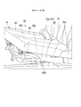
- FIG. 1 is a perspective view showing a vehicle interior area A shown in FIG. 1 in an enlarged manner in a vehicle equipped with an in-vehicle antenna arrangement structure according to an embodiment of the present invention, which is transmitted through a leg portion of a seat and a cover member.
- FIG. It is a side view which shows the change of the state accompanying the tumble operation
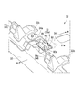
- FIG. 1 is a side sectional view of a peripheral portion of an in-vehicle antenna arrangement structure in a vehicle equipped with an in-vehicle antenna arrangement structure according to an embodiment of the present invention. It is a perspective view which shows the antenna unit arrange
- FIG. 7 is a cross-sectional view showing the inside of the cover member by breaking the cover member of the in-vehicle antenna arrangement structure according to the embodiment of the present invention, and is a cross-sectional view of the VII-VII cross section shown in FIG. It is a perspective view of the cover member of the in-vehicle antenna arrangement structure concerning the embodiment of the present invention. It is a top view of the cover member of the in-vehicle antenna arrangement structure concerning the embodiment of the present invention. It is a perspective view showing the state where the effective area of the floor surface of the luggage compartment was expanded by the seat being flipped forward in the vehicle equipped with the in-vehicle antenna arrangement structure according to the embodiment of the present invention.
- the in-vehicle antenna arrangement structure 10 is provided in the room 2 of the vehicle 1 as shown in FIGS.
- the vehicle 1 includes, for example, a first-row seat 4, a second-row seat 5, and a third-row seat 6 arranged in three rows from the front FR in the vehicle front-rear direction to the rear RR on the floor 3. .
- the vehicle interior antenna arrangement structure 10 is provided, for example, below the third row seat 6.
- the first row sheet 4 is provided on the first floor 31.
- the first floor 31 is connected to the second floor 32 that is higher in the vertical direction than the first floor 31.
- the second row seat 5 is provided on the second floor 32.
- the second floor 32 is connected to a third floor 33 that is higher in the vertical direction than the second floor 32.
- the third row seat 6 is provided on the third floor 33.
- the third floor 33 forms a floor of the luggage compartment 7 provided in the rear RR of the third row seat 6.
- a floor carpet 34 is laid on the surface of the floor 3.
- the third row seat 6 is, for example, a so-called bench seat in which the left and right are integrally formed.
- the third row of seats 6 is configured to be able to perform a so-called tumble operation in which the seat back 61 is flipped up to the front FR in a state where the seat back 61 is folded so as to be folded on the seating surface 62a of the seat cushion 62 (all-falling state). Yes.
- the seat back 61 of the third row seat 6 is coupled to the seat cushion 62 by a reclining mechanism 63 provided at the rear end portion of the seat cushion 62.
- the reclining mechanism 63 supports the seat back 61 so as to be rotatable around an axis of a rotating shaft 63a extending in parallel with the vehicle width direction.
- the reclining mechanism 63 appropriately maintains the posture of the seat back 61 that rotates around the axis of the rotating shaft 63a, and when a release operation member (not shown) such as a lever and a strap is operated by an operator, Release posture maintenance.
- the seat cushion 62 of the third row seat 6 is fixed on the surface (floor surface) 33a of the third floor 33 by a front leg portion 64 and a rear leg portion 65 provided on the lower surface 62b.
- the thickness of the seat cushion 62 is formed thinner than the thickness of each seat cushion of the first row seat 4 and the second row seat 5, for example.
- the front leg portion 64 is fixed to the front fixing portion 33 b on the floor surface 33 a of the third floor 33.
- the front leg portion 64 supports the front end portion of the seat cushion 62 so as to be rotatable around an axis of a rotation shaft 64a extending in parallel with the vehicle width direction.
- the front leg portion 64 incorporates a biasing member (not shown) such as a spring that biases the seat cushion 62 so as to rotate around the axis of the rotation shaft 64a.
- the rear leg portion 65 is fixed to the rear end portion of the lower surface 62b of the seat cushion 62.
- the rear leg portion 65 is releasably fixed to a rear fixing portion 33 c provided on the floor surface 33 a of the third floor 33.
- the rear fixing portion 33c releases the fixing of the rear leg portion 65 in a state where the seat back 61 is folded so as to be folded on the seating surface 62a of the seat cushion 62 (totally falling state), and the rear leg portion is not in the fully falling state. Keep 65 fixed.
- the third row seat 6 is in a standard state in which an occupant can be seated.
- the reclining mechanism 63 maintains the posture of the seat back 61 in an appropriate posture (for example, a posture of standing up to the rear RR).
- the rear leg portion 65 is fixed to a rear fixing portion 33 c provided on the floor surface 33 a of the third floor 33.
- the seat cushion 62 is disposed so as to straddle part of the floor surface 33 a of the luggage compartment 7 of the vehicle 1.
- the reclining mechanism 63 releases the posture maintenance of the seat back 61.
- the reclining mechanism 63 rotates the seat back 61 around the rotation shaft 63a so as to tilt forward (state 1).
- the reclining mechanism 63 rotates the seat back 61 around the rotation shaft 63a.
- the reclining mechanism 63 rotates the seat back 61 until the seat back 61 is brought into a state where the seat back 61 is folded over the seating surface 62a of the seat cushion 62 (a total fall state).
- the rear fixing portion 33c releases the fixing of the rear leg portion 65 (state 2).
- the front leg portion 64 moves the seat cushion 62 around the rotation shaft 64a so that the rear end portion of the seat cushion 62 jumps up to the front FR by the biasing force of a built-in biasing member (not shown).
- a built-in biasing member not shown.
- Rotate to The seat back 61 and the seat cushion 62 rotate toward the front FR with the front end portion of the seat cushion 62 as a fulcrum (state 3).
- the vehicle interior antenna arrangement structure 10 includes an antenna unit 80 attached to the room 2 of the vehicle 1.
- the antenna unit 80 includes an antenna 81, a housing 82 that accommodates the antenna 81, a harness 83 that is pulled out from the inside of the housing 82, and a cover member 84 that covers the housing 82.
- a cover 64 c is attached to the front leg portion 64.
- the antenna unit 80 is, for example, a smart entry unit of a smart entry system.
- the smart entry unit includes a receiving circuit that communicates with a portable device possessed by a passenger of the vehicle 1, a receiving antenna 81, and the like inside the housing 82.
- a portable device possessed by a passenger of the vehicle 1 functions as an electronic key of the vehicle 1.
- the portable device transmits a response signal in response to a request signal transmitted from the vehicle 1, a command signal instructing operation of a predetermined on-vehicle device, and the like together with unique identification information.
- the receiving antenna 81 is, for example, an RF (Radio-Frequency) antenna.
- the smart entry unit is connected to a control unit of the smart entry system, an unlock sensor, a transmission circuit, a transmission antenna, and the like by a CAN communication line that is a general-purpose communication line provided in the harness 83.
- the control unit includes a processor such as a CPU, a ROM that stores programs, and a RAM that temporarily stores data.
- An unlock sensor is arrange
- the transmission circuit communicates with the portable device.
- the transmission antenna is, for example, an LF (Low Frequency) antenna.
- the control unit of the smart entry system periodically transmits a request signal based on an LF signal from a transmitting antenna within a predetermined communication range in the vicinity.
- the control unit compares the identification information included in the response signal with the previously stored identification information when the reception antenna 81 receives a response signal based on the RF signal from the portable device that responds to the request signal. To do.
- the control unit detects that communication between the portable device and the reception circuit and the transmission circuit is established, and an operator who owns the portable device Authenticate that you are a legitimate operator. After authenticating that the operator of the portable device is a legitimate operator, the control unit instructs the operation of a predetermined in-vehicle device according to a command signal output from the portable device.
- the antenna unit 80 is disposed below the seat cushion 62 of the third row seat 6 on the surface (floor surface) 33 a of the third floor 33 of the vehicle 1.
- the antenna unit 80 is disposed, for example, at a position closer to the front FR than the center portion of the seat surface 62a of the seat cushion 62 in the vehicle front-rear direction.
- the casing 82 is attached to a bracket 91 fixed on the floor surface 33 a of the third floor 33.
- the harness 83 is disposed between the floor 3 and the floor carpet 34 so as to extend from the floor surface 33a of the third floor 33 toward the surface (floor surface) of the second floor 32.
- the casing 82 may include a waterproof shield formed by, for example, a resin mold.
- the rear end portion 91 a of the bracket 91 is covered with the floor carpet 34. Parts other than the rear end portion 91a of the bracket 91 are exposed to the room 2 from a cutout portion 34a formed in the floor carpet 34. As shown in FIGS. 6 and 7, the bracket 91 is formed with a fixing hole 91 b for fixing the housing 82 and a mounting hole 91 c for fixing the cover member 84. The bracket 91 exposes the portion where the fixing hole 91 b and the mounting hole 91 c are formed to the room 2 from the notch 34 a of the floor carpet 34.
- the bracket 91 fixes the casing 82 by attaching a hook-shaped fixing member 92 to a casing bracket 82a extending from the casing 82 and a fixing hole 91b.
- the bracket 91 fixes the cover member 84 by mounting a snap-fit clip member 84a protruding inward from the inner surface of the cover member 84 into the mounting hole 91c.
- the bracket 91 assists the positioning and fixing of the cover member 84 by attaching the front end portion 91 d to the guide hook 84 b of the cover member 84.
- the cover member 84 has a substantially rectangular shape in a plan view as viewed from the vertical direction, and is substantially in a side view as viewed from the vehicle width direction. It is formed in a triangular box shape.
- the cover member 84 is made of a material such as resin, for example.
- the cover member 84 includes a surface 84 c that faces the surface (that is, the lower surface 62 b) of the seat cushion 62 on the floor surface 33 a side.
- the shape of the surface 84c is formed so as to incline downward from the front FR in the vehicle front-rear direction toward the rear RR so as to follow the inclination of the seat surface 62a of the seat cushion 62.
- a predetermined distance L is provided between the lower surface 62 b of the seat cushion 62 and the surface 84 c of the cover member 84.
- the predetermined distance L ensures a desired distance (clearance) between the lower surface 62b of the seat cushion 62 and the surface 84c of the cover member 84 even when the seat surface 62a sinks due to the passenger sitting on the seat cushion 62. Is set to
- the cover member 84 covers the antenna unit 80 exposed to the room 2 from the notch 34a of the floor carpet 34. As shown in FIG. 7, the cover member 84 has a peripheral portion 34 b of the cutout portion 34 a of the floor carpet 34, from both sides in the thickness direction by the floor surface 33 a of the third floor 33 and the rear end portion 91 a of the bracket 91. It is pinched so as to be pinched.
- the cover member 84 includes a clip member 84 a that protrudes from the inner surface, a guide hook 84 b that is provided on the inner surface of the front portion, and a plurality that is provided so as to protrude from the inner surface.
- Rib 84d The clip member 84 a is, for example, a snap-fit type fixing member, and fixes the cover member 84 to the bracket 91 by being inserted into the mounting hole 91 c of the bracket 91.
- the guide hook 84b includes, for example, an insertion hole formed in the front portion of the cover member 84, and assists the positioning and fixing of the cover member 84 with respect to the bracket 91 by inserting the front end portion 91d of the bracket 91.
- the plurality of ribs 84d are provided on the inner surface of the cover member 84 so as to extend in the vehicle front-rear direction and the vehicle width direction, for example.
- the cover member 84 protrudes above the floor carpet 34 in the vertical direction on the floor surface 33 a of the third floor 33. As shown in FIG. 10, the cover member 84 has the seat back 61 and the seat cushion 62 tilted forward FR by the tumble operation of the third row seat 6, and the effective area of the floor surface 33a of the cargo compartment 7 is expanded. In some cases, it is exposed to the room 2.
- the cover member 84 moves the load C loaded on the floor surface 33a of the luggage compartment 7 to the front FR in the vehicle front-rear direction when the seat back 61 and the seat cushion 62 are in the standing state (state 4 shown in FIG. 3). It functions as a regulating member that regulates.
- the cover member 84 is also used for a small load C that moves between the seat cushion 62 and the floor surface 33a in a state other than the standing state of the seat back 61 and the seat cushion 62 (state 4 shown in FIG. 3). , It functions as a regulating member that regulates movement to the forward FR.
- the states other than the state 4 shown in FIG. 3 are, for example, a standard state in which an occupant can be seated, a state 1, a state 2, and a state 3 shown in FIG.
- the antenna unit 80 is disposed below the seat cushion 62, that is, at a position where no stepping on by an occupant is performed, and thus the antenna unit 80 is well protected. be able to. Since the cover member 84 is provided, the antenna unit 80 can be satisfactorily protected by the cover member 84 even when the seat cushion 62 of the third row seat 6 moves from the floor surface 33a.
- the cover member 84 protrudes above the floor carpet 34 on the floor surface 33a in the vertical direction, the cover member 84 is moved to the forward FR of the load C loaded on the floor surface 33a of the luggage compartment 7. It can function as a regulating member for regulating.
- the cover member 84 in a mode in which the effective area of the floor surface 33a of the luggage compartment 7 is expanded by a tumble operation of the third row seat 6, the cover member 84 can function as a restricting member. Thereby, for example, it is possible to stably hold the load C without the need to provide a dedicated stopper or the like for restricting the movement of the load C.
- the cover member 84 sandwiches the floor carpet 34 between the floor surface 33a of the third floor 33 and the rear end portion 91a of the bracket 91, the cover member 84 can function as a holding member for the floor carpet 34.
- the antenna 81 is disposed on the floor surface 33a of the third floor 33 which is higher in the vertical direction than the first floor 31 and the second floor 32, the directivity characteristics of the antenna 81 with respect to the interior space can be improved. it can. Furthermore, compared to the first row seat 4 and the second row seat 5, the antenna unit 80 is disposed below the third row seat 6 in the rearmost RR, where a space is easily formed below the seat cushion 62, so that the space Efficiency can be improved most.
- the casing 82 includes a waterproof shield, the desired waterproofness can be ensured even if the antenna unit 80 protrudes above the floor carpet 34 in the vertical direction on the floor surface 33a. Since the antenna unit 80 is disposed at a position closer to the front FR than the center portion of the seating surface 62a of the seat cushion 62, the seat cushion 62 is depressed even when the seating surface 62a of the seat cushion 62 sinks due to the occupant sitting. It is easy to secure a desired interval (clearance) between 62 and the cover member 84. Furthermore, when the effective area of the floor surface 33a of the luggage compartment 7 is expanded by the tumble operation of the third row seat 6, the effective area of the luggage compartment 7 can be expanded to the maximum extent.
- the cover member 84 includes a plurality of ribs 84d, load resistance can be improved even when a load is applied by the load C in the luggage compartment 7 or the like.
- the antenna unit 80 is provided below the third row seat 6, but is not limited thereto.
- the antenna unit 80 may be provided below another sheet.
- the antenna unit 80 may be mounted on a vehicle in which seats are arranged in a number other than three rows.
- the antenna unit 80 is disposed at a position closer to the front FR than the central portion of the seating surface 62a of the seat cushion 62, but is not limited thereto.
- the antenna unit 80 may be disposed at the center of the seat surface 62a of the seat cushion 62, or at a position closer to the rear RR than the center.
- the third row seat 6 is configured to be capable of tumble operation, but is not limited thereto.
- the third row seat 6 may be configured to be capable of chip-up operation, for example.
- the antenna unit 80 includes the receiving circuit and the antenna 81, but is not limited thereto.
- the antenna unit 80 may include only the antenna 81 without including the receiving circuit.
- the antenna unit 80 is disposed at a position where no occupant steps on the antenna unit 80, it is possible to satisfactorily protect the antenna unit 80 in the vehicle while preventing the design and processing from becoming complicated.
- An in-vehicle antenna arrangement structure can be provided.
Landscapes
- Engineering & Computer Science (AREA)
- Mechanical Engineering (AREA)
- Aviation & Aerospace Engineering (AREA)
- Transportation (AREA)
- Seats For Vehicles (AREA)
Abstract
車内アンテナ配置構造(10)は、アンテナユニット(80)を備える。アンテナユニット(80)は、アンテナと、アンテナを収容する筐体(82)とを有する。アンテナユニット(80)は、車両の室内に取り付けられる。アンテナユニット(80)は、車両のフロア面(33a)上において車両のシートクッション(62)の下方に配置される。アンテナユニット(80)は、筐体(82)を覆うカバー部材(84)を備える。
Description
本発明は、車内アンテナ配置構造に関する。
従来、車両の乗員が所持する携帯機との通信を行うアンテナが配置される凹部が形成されたフロアマットまたはフロアボードを備える車両のアンテナ配置構造が知られている(例えば、特許文献1および特許文献2参照)。この車両のアンテナ配置構造は、アンテナが埋設された凹部を覆うように敷かれたフロアカーペットを備えている。
しかしながら、上記従来技術に係る車両のアンテナ配置構造によれば、アンテナを配置するための凹部が設けられたフロアマットまたはフロアボードを備える必要があり、設計および加工が複雑化するという問題が生じる。さらに、アンテナが配置される車内のフロアは、乗員によって容易に踏みつけられるので、凹部を覆うフロアカーペットではアンテナの保護が十分ではないという問題があった。
本発明は上記事情に鑑みてなされたもので、設計および加工が複雑化することを防ぎながら、車内のアンテナを保護することが可能な車内アンテナ配置構造を提供することを目的とする。
上記課題を解決して係る目的を達成するために、本発明は以下の態様を採用した。
(1)本発明の一態様に係る車内アンテナ配置構造は、アンテナと、前記アンテナを収容する筐体とを有し、車両の室内に取り付けられるアンテナユニットを備えるアンテナ配置構造であって、前記アンテナユニットは、前記車両のフロア面上において前記車両のシートクッションの下方に配置され、前記筐体を覆うカバー部材を備える。
(1)本発明の一態様に係る車内アンテナ配置構造は、アンテナと、前記アンテナを収容する筐体とを有し、車両の室内に取り付けられるアンテナユニットを備えるアンテナ配置構造であって、前記アンテナユニットは、前記車両のフロア面上において前記車両のシートクッションの下方に配置され、前記筐体を覆うカバー部材を備える。
(2)上記(1)に記載の車内アンテナ配置構造は、前記シートクッションは、前記車両の荷室のフロア面の一部に跨るように配置され、前記フロア面における車両前後方向の前方および後方の各々の固定部に固定され、前記シートクッションは、前記車両前後方向の後方の前記固定部における固定が解除された場合に、前記車両前後方向の前方に傾動可能であり、前記カバー部材は、前記荷室のフロア面上に積載される荷物の前記車両前後方向における前方への移動を規制する規制部材を兼ねてもよい。
(3)上記(1)または(2)に記載の車内アンテナ配置構造では、前記シートクッションは、前記車両前後方向における前方から後方に向かって座面が下がるように傾斜した状態で前記フロア面に固定され、前記カバー部材の形状は、前記シートクッションの前記フロア面側の表面と対向する面が前記シートクッションの前記座面の傾斜に沿うように、前記車両前後方向における前方から後方に向かって傾斜する形状に形成されてもよい。
(4)上記(1)から(3)の何れか1つに記載の車内アンテナ配置構造は、前記フロア面に敷設され、前記フロア面と前記カバー部材とによって挟持されるフロアカーペットを備えてもよい。
(5)上記(1)から(4)の何れか1つに記載の車内アンテナ配置構造では、前記アンテナユニットが配置される前記シートクッションの下方のフロア面は、当該シートクッションを有する前記シートとは異なる他のシートが取り付けられる前記フロア面の部位よりも鉛直方向に高い位置に配置されてもよい。
(6)上記(1)から(5)の何れか1つに記載の車内アンテナ配置構造は、前記車両の室内において、車両前後方向に亘って3列に配置されるシートを備え、前記アンテナユニットは、前記3列のシートのうち最も後方の列のシートの前記シートクッションの下方に配置されてもよい。
上記(1)に記載の態様に係る車内アンテナ配置構造によれば、アンテナユニットは乗員による踏みつけが無い位置に配置されるので、アンテナユニットを良好に保護することができる。車両のシートクッションがフロア面上から移動した場合であっても、カバー部材によってアンテナユニットを良好に保護することができる。
さらに、上記(2)の場合、車両のシートのチップアップまたはタンブルなどによって、荷室のフロア面の有効領域が拡張されるモードにおいて、カバー部材を規制部材として機能させることができる。これにより、例えば荷物の移動を規制するための専用のストッパーなどを設ける必要無しに、安定的に荷物を保持することができる。
さらに、上記(3)の場合、乗員がシートに着座することによってシートクッションの座面が沈み込む場合でも、シートクッションとカバー部材との間に所望の距離(クリアランス)を確保することができる。
さらに、上記(4)の場合、カバー部材をフロアカーペットの保持部材として機能させることができる。
さらに、上記(5)の場合、アンテナを他のシートが取り付けられるフロア面に配置する場合に比べて、車内空間に対する指向特性をより向上させることができる。
さらに、上記(6)の場合、3列のシートのうちシートクッションの下方にスペースが形成され易い最も後方のシートの下方にアンテナユニットが配置されるので、スペース効率を最も向上させることができる。
さらに、上記(5)の場合、アンテナを他のシートが取り付けられるフロア面に配置する場合に比べて、車内空間に対する指向特性をより向上させることができる。
さらに、上記(6)の場合、3列のシートのうちシートクッションの下方にスペースが形成され易い最も後方のシートの下方にアンテナユニットが配置されるので、スペース効率を最も向上させることができる。
以下、本発明の車内アンテナ配置構造の一実施形態について添付図面を参照しながら説明する。
本実施形態による車内アンテナ配置構造10は、図1および図2に示すように、車両1の室内2に設けられている。車両1は、例えば、フロア3上において車両前後方向の前方FRから後方RRに向かって3列に配置された1列目シート4、2列目シート5、および3列目シート6を備えている。車内アンテナ配置構造10は、例えば、3列目シート6の下方に設けられている。
1列目シート4は、第1フロア31に設けられている。第1フロア31は、第1フロア31よりも鉛直方向に高い位置の第2フロア32に接続されている。2列目シート5は、第2フロア32に設けられている。第2フロア32は、第2フロア32よりも鉛直方向に高い位置の第3フロア33に接続されている。3列目シート6は、第3フロア33に設けられている。第3フロア33は、3列目シート6の後方RRに設けられる荷室7のフロアを形成している。なお、フロア3の表面上には、フロアカーペット34が敷設されている。
3列目シート6は、例えば、左右が一体に形成された、いわゆるベンチシートである。3列目シート6は、シートバック61がシートクッション62の座面62a上に折り重なるように倒れた状態(全倒れ状態)で全体を前方FRに跳ね上げる動作、いわゆるタンブル動作が可能に構成されている。
3列目シート6のシートバック61は、シートクッション62の後端部に設けられたリクライニング機構63によってシートクッション62に連結されている。リクライニング機構63は、シートバック61を車幅方向に平行に伸びる回転軸63aの軸周りに回転可能に支持している。リクライニング機構63は、回転軸63aの軸周りに回転するシートバック61の姿勢を適宜に維持するとともに、レバーおよびストラップなどの解除操作部材(図示略)が操作者によって操作されるとシートバック61の姿勢維持を解除する。
3列目シート6のシートクッション62は、下面62bに設けられた前方脚部64および後方脚部65によって第3フロア33の表面(フロア面)33a上に固定されている。シートクッション62の厚さは、例えば、1列目シート4および2列目シート5の各々のシートクッションの厚さよりも肉薄に形成されている。
前方脚部64は、第3フロア33のフロア面33a上の前方固定部33bに固定されている。前方脚部64は、シートクッション62の前端部を車幅方向に平行に伸びる回転軸64aの軸周りに回転可能に支持している。前方脚部64は、シートクッション62を回転軸64aの軸周りに回転させるように付勢するスプリングなどの付勢部材(図示略)を内蔵している。
後方脚部65は、シートクッション62の下面62bの後端部に固定されている。後方脚部65は、第3フロア33のフロア面33a上に設けられた後方固定部33cに解除可能に固定される。後方固定部33cは、例えば、シートバック61がシートクッション62の座面62a上に折り重なるに倒れた状態(全倒れ状態)で後方脚部65の固定を解除し、全倒れ状態以外において後方脚部65の固定を維持する。
以下に、3列目シート6のタンブル動作について、図3を参照して説明する。
なお、タンブル動作の開始前において、3列目シート6は、乗員の着座が可能な標準状態である。この標準状態において、リクライニング機構63は、シートバック61の姿勢を適宜の姿勢(例えば、後方RRに立ち上がった姿勢など)に維持している。後方脚部65は、第3フロア33のフロア面33a上に設けられた後方固定部33cに固定されている。シートクッション62は、車両1の荷室7のフロア面33aの一部に跨るように配置されている。
なお、タンブル動作の開始前において、3列目シート6は、乗員の着座が可能な標準状態である。この標準状態において、リクライニング機構63は、シートバック61の姿勢を適宜の姿勢(例えば、後方RRに立ち上がった姿勢など)に維持している。後方脚部65は、第3フロア33のフロア面33a上に設けられた後方固定部33cに固定されている。シートクッション62は、車両1の荷室7のフロア面33aの一部に跨るように配置されている。
先ず、標準状態において、操作者によって解除操作部材(図示略)が操作されると、リクライニング機構63はシートバック61の姿勢維持を解除する。リクライニング機構63は、シートバック61の姿勢維持を解除すると、シートバック61を前傾させるように回転軸63aの軸周りに回転させる(状態1)。
次に、操作者によって全倒れ操作部材(図示略)が操作されると、リクライニング機構63は、シートバック61を回転軸63aの軸周りに回転させる。リクライニング機構63は、シートバック61がシートクッション62の座面62a上に折り重なるように倒れた状態(全倒れ状態)となるまで、シートバック61を回転させる。全倒れ状態において、後方固定部33cは、後方脚部65の固定を解除する(状態2)。
次に、前方脚部64は、内蔵された付勢部材(図示略)の付勢力によって、シートクッション62の後端部を前方FRに跳ね上げるように、シートクッション62を回転軸64aの軸周りに回転させる。シートバック61およびシートクッション62は、シートクッション62の前端部を支点として、前方FRに向かって回転する(状態3)。
次に、シートクッション62の前端部を支点とするシートバック61およびシートクッション62の回転は、回転規制部材(図示略)によって停止させられる。シートバック61およびシートクッション62は、回転規制部材(図示略)によって起立状態を維持する(状態4)。
以下に、標準状態の3列目シート6の下方に設けられている車内アンテナ配置構造10について説明する。
車内アンテナ配置構造10は、図4および図5に示すように、車両1の室内2に取り付けられるアンテナユニット80を備えている。アンテナユニット80は、アンテナ81と、アンテナ81を収容する筐体82と、筐体82の内部から外部に引き出されたハーネス83と、筐体82を覆うカバー部材84と、を備えている。
なお、図5において前方脚部64にはカバー64cが装着されている。
なお、図5において前方脚部64にはカバー64cが装着されている。
アンテナユニット80は、例えば、スマートエントリシステムのスマートエントリユニットである。スマートエントリユニットは、車両1の乗員が所持する携帯機と通信する受信回路と、受信用のアンテナ81となどを、筐体82の内部に備えている。車両1の乗員が所持する携帯機は、車両1の電子キーとして機能する。携帯機は、車両1から送信されるリクエスト信号に応答する応答信号、および所定の車載機器の作動を指示する指令信号などを、固有の識別情報とともに送信する。受信用のアンテナ81は、例えば、RF(Radio Frequency)アンテナである。スマートエントリユニットは、ハーネス83に備えられる汎用の通信ラインであるCAN通信ラインなどによって、スマートエントリシステムの制御ユニット、アンロックセンサ、送信回路、および送信用のアンテナなどに接続されている。制御ユニットは、CPUなどのプロセッサ、プログラムを格納するROM、およびデータを一時的に記憶するRAMなどを備えている。アンロックセンサは、車両1のドアのドアハンドル周辺に配置され、乗員によるドアの解錠指示を検出する。送信回路は、携帯機と通信する。送信用のアンテナは、例えば、LF(Low Frequency)アンテナである。
スマートエントリシステムの制御ユニットは、送信用のアンテナから周辺の所定の通信範囲内に定期的にLF信号によるリクエスト信号を送信する。制御ユニットは、リクエスト信号に応答する携帯機からのRF信号による応答信号を受信用のアンテナ81が受信した場合に、この応答信号に含まれる識別情報と、予め記憶している識別情報とを比較する。制御ユニットは、受信した識別情報と記憶している識別情報とが一致する場合に、携帯機と受信回路および送信回路との通信が成立したことを検出するとともに、携帯機を所持する操作者が正規の操作者であると認証する。制御ユニットは、携帯機の操作者が正規の操作者であると認証した後、携帯機から出力される指令信号に応じて、所定の車載機器の作動を指示する。
アンテナユニット80は、車両1の第3フロア33の表面(フロア面)33a上において3列目シート6のシートクッション62の下方に配置されている。アンテナユニット80は、例えば、車両前後方向におけるシートクッション62の座面62aの中央部よりも前方FR寄りの位置に配置されている。
筐体82は、第3フロア33のフロア面33a上に固定されたブラケット91に装着されている。ハーネス83は、例えば、第3フロア33のフロア面33a上から第2フロア32の表面(フロア面)上に向かって伸びるように、フロア3とフロアカーペット34との間に配置されている。なお、筐体82は、例えば樹脂モールドなどによって形成される防水シールドを備えてもよい。
筐体82は、第3フロア33のフロア面33a上に固定されたブラケット91に装着されている。ハーネス83は、例えば、第3フロア33のフロア面33a上から第2フロア32の表面(フロア面)上に向かって伸びるように、フロア3とフロアカーペット34との間に配置されている。なお、筐体82は、例えば樹脂モールドなどによって形成される防水シールドを備えてもよい。
ブラケット91の後端部91aは、フロアカーペット34によって覆われている。ブラケット91の後端部91a以外の部位は、フロアカーペット34に形成された切り欠き部34aから室内2に露出している。
ブラケット91には、図6および図7に示すように、筐体82を固定するための固定穴91bと、カバー部材84を固定するための装着孔91cとが形成されている。ブラケット91は、固定穴91bおよび装着孔91cの各々が形成された部位をフロアカーペット34の切り欠き部34aから室内2に露出させている。
ブラケット91には、図6および図7に示すように、筐体82を固定するための固定穴91bと、カバー部材84を固定するための装着孔91cとが形成されている。ブラケット91は、固定穴91bおよび装着孔91cの各々が形成された部位をフロアカーペット34の切り欠き部34aから室内2に露出させている。
ブラケット91は、筐体82から伸びる筐体ブラケット82aおよび固定穴91bに鋲型の固定部材92が装着されることによって筐体82を固定する。
ブラケット91は、カバー部材84の内面上から内部に突出するスナップフィット型のクリップ部材84aが装着孔91cに装着されることによってカバー部材84を固定する。
ブラケット91は、前端部91dが、カバー部材84のガイドフック84bに装着されることによって、カバー部材84の位置決めおよび固定を補助する。
ブラケット91は、カバー部材84の内面上から内部に突出するスナップフィット型のクリップ部材84aが装着孔91cに装着されることによってカバー部材84を固定する。
ブラケット91は、前端部91dが、カバー部材84のガイドフック84bに装着されることによって、カバー部材84の位置決めおよび固定を補助する。
カバー部材84の形状は、図5、図6、図7、図8、および図9に示すように、鉛直方向から見た平面視でほぼ長方形状、かつ車幅方向から見た側面視でほぼ三角形状の箱型に形成されている。カバー部材84は、例えば、樹脂などの材料によって形成されている。カバー部材84は、図4に示すように、シートクッション62のフロア面33a側の表面(つまり下面62b)と対向する表面84cを備えている。表面84cの形状は、シートクッション62の座面62aの傾斜に沿うように、車両前後方向における前方FRから後方RRに向かって下降傾斜するように形成されている。シートクッション62の下面62bと、カバー部材84の表面84cとの間には、所定距離Lが設けられている。所定距離Lは、乗員がシートクッション62に着座することによって座面62aが沈み込む場合でも、シートクッション62の下面62bとカバー部材84の表面84cとの間に所望の間隔(クリアランス)を確保するように設定されている。
カバー部材84は、フロアカーペット34の切り欠き部34aから室内2に露出するアンテナユニット80を覆う。カバー部材84は、図7に示すように、フロアカーペット34の切り欠き部34aの周辺部34bを、第3フロア33のフロア面33aおよびブラケット91の後端部91aとによって厚さ方向の両側から挟み込むように挟持している。
カバー部材84は、図7および図9に示すように、内面上から突出するクリップ部材84aと、前方部の内面上に設けられたガイドフック84bと、内面上か突出するように設けられた複数のリブ84dと、を備えている。
クリップ部材84aは、例えば、スナップフィット型の固定部材であり、ブラケット91の装着孔91cに差し込まれることによって、カバー部材84をブラケット91に固定する。
ガイドフック84bは、例えば、カバー部材84の前方部に形成された差し込み穴を備えており、ブラケット91の前端部91dが差し込まれることによって、ブラケット91に対するカバー部材84の位置決めおよび固定を補助する。
複数のリブ84dは、カバー部材84の内面上において、例えば、車両前後方向および車幅方向の各々に伸びるように設けられている。
クリップ部材84aは、例えば、スナップフィット型の固定部材であり、ブラケット91の装着孔91cに差し込まれることによって、カバー部材84をブラケット91に固定する。
ガイドフック84bは、例えば、カバー部材84の前方部に形成された差し込み穴を備えており、ブラケット91の前端部91dが差し込まれることによって、ブラケット91に対するカバー部材84の位置決めおよび固定を補助する。
複数のリブ84dは、カバー部材84の内面上において、例えば、車両前後方向および車幅方向の各々に伸びるように設けられている。
カバー部材84は、第3フロア33のフロア面33a上において、鉛直方向の上方にフロアカーペット34よりも突出している。
カバー部材84は、図10に示すように、3列目シート6のタンブル動作によってシートバック61およびシートクッション62が前方FRに傾動して、荷室7のフロア面33aの有効領域が拡張された場合に室内2に露出する。カバー部材84は、シートバック61およびシートクッション62の起立状態(図3に示す状態4)において、荷室7のフロア面33a上に積載される荷物Cの車両前後方向の前方FRへの移動を規制する規制部材として機能する。
さらに、カバー部材84は、シートバック61およびシートクッション62の起立状態(図3に示す状態4)以外の状態において、シートクッション62とフロア面33aとの間を移動する小さな荷物Cに対しても、前方FRへの移動を規制する規制部材として機能する。図3に示す状態4以外の状態は、例えば、乗員の着座が可能な標準状態と、図3に示す状態1、状態2、および状態3となどである。
上述したように、本実施形態による車内アンテナ配置構造10によれば、アンテナユニット80は、シートクッション62の下方、つまり乗員による踏みつけが無い位置に配置されるので、アンテナユニット80を良好に保護することができる。カバー部材84を備えるので、3列目シート6のシートクッション62がフロア面33a上から移動した場合であっても、カバー部材84によってアンテナユニット80を良好に保護することができる。
さらに、カバー部材84はフロア面33a上において鉛直方向の上方にフロアカーペット34よりも突出しているので、カバー部材84を荷室7のフロア面33aに積載される荷物Cの前方FRへの移動を規制する規制部材として機能させることができる。例えば、3列目シート6のタンブル動作などによって、荷室7のフロア面33aの有効領域が拡張されるモードにおいて、カバー部材84を規制部材として機能させることができる。これにより、例えば荷物Cの移動を規制するための専用のストッパーなどを設ける必要無しに、安定的に荷物Cを保持することができる。
さらに、乗員が3列目シート6に着座することによってシートクッション62の座面62aが沈み込む場合でも、シートクッション62とカバー部材84との間に所望の間隔(クリアランス)を確保することができる。
さらに、カバー部材84は、第3フロア33のフロア面33aおよびブラケット91の後端部91aとによってフロアカーペット34を挟み込むので、カバー部材84をフロアカーペット34の保持部材として機能させることができる。
さらに、カバー部材84は、第3フロア33のフロア面33aおよびブラケット91の後端部91aとによってフロアカーペット34を挟み込むので、カバー部材84をフロアカーペット34の保持部材として機能させることができる。
さらに、第1フロア31および第2フロア32よりも鉛直方向に高い位置の第3フロア33のフロア面33a上にアンテナ81が配置されるので、車内空間に対するアンテナ81の指向特性を向上させることができる。
さらに、1列目シート4および2列目シート5に比べて、シートクッション62の下方にスペースが形成され易い最も後方RRの3列目シート6の下方にアンテナユニット80が配置されるので、スペース効率を最も向上させることができる。
さらに、1列目シート4および2列目シート5に比べて、シートクッション62の下方にスペースが形成され易い最も後方RRの3列目シート6の下方にアンテナユニット80が配置されるので、スペース効率を最も向上させることができる。
さらに、筐体82は、防水シールドを備えているので、アンテナユニット80がフロア面33a上において鉛直方向の上方にフロアカーペット34よりも突出していても所望の防水性を確保することができる。
アンテナユニット80は、シートクッション62の座面62aの中央部よりも前方FR寄りの位置に配置されているので、乗員が着座することによってシートクッション62の座面62aが沈み込む場合でも、シートクッション62とカバー部材84との間に所望の間隔(クリアランス)を確保しやすい。さらに、3列目シート6のタンブル動作によって荷室7のフロア面33aの有効領域が拡張される際に、荷室7の有効領域を最大限に拡張することができる。
アンテナユニット80は、シートクッション62の座面62aの中央部よりも前方FR寄りの位置に配置されているので、乗員が着座することによってシートクッション62の座面62aが沈み込む場合でも、シートクッション62とカバー部材84との間に所望の間隔(クリアランス)を確保しやすい。さらに、3列目シート6のタンブル動作によって荷室7のフロア面33aの有効領域が拡張される際に、荷室7の有効領域を最大限に拡張することができる。
さらに、カバー部材84は複数のリブ84dを備えているので、荷室7の荷物Cなどによって荷重がかかる場合であっても、耐荷重性を向上させることができる。
なお、上述した実施形態において、アンテナユニット80は、3列目シート6の下方に設けられるとしたが、これに限定されない。アンテナユニット80は、他のシートの下方に設けられてもよい。
また、アンテナユニット80は、3列以外の列数にシートが配置された車両に搭載されてもよい。
また、アンテナユニット80は、3列以外の列数にシートが配置された車両に搭載されてもよい。
なお、上述した実施形態において、アンテナユニット80は、シートクッション62の座面62aの中央部よりも前方FR寄りの位置に配置されるとしたが、これに限定されない。
アンテナユニット80は、シートクッション62の座面62aの中央部、または中央部よりも後方RR寄りの位置に配置されてもよい。
アンテナユニット80は、シートクッション62の座面62aの中央部、または中央部よりも後方RR寄りの位置に配置されてもよい。
なお、上述した実施形態において、3列目シート6はタンブル動作が可能に構成されているとしたが、これに限定されない。3列目シート6は、例えば、チップアップ動作が可能に構成されてもよい。
なお、上述した実施形態において、アンテナユニット80は、受信回路と、アンテナ81とを備えるとしたが、これに限定されない。
アンテナユニット80は、受信回路を備えずに、アンテナ81のみを備えてもよい。
アンテナユニット80は、受信回路を備えずに、アンテナ81のみを備えてもよい。
上述の実施形態は、例として提示したものであり、発明の範囲を限定することは意図していない。上述の新規な実施形態は、その他の様々な形態で実施されることが可能であり、発明の要旨を逸脱しない範囲で、種々の省略、置き換え、変更を行うことができる。上述の実施形態やその変形は、発明の範囲や要旨に含まれるとともに、特許請求の範囲に記載された発明とその均等の範囲に含まれる。
本発明によれば、アンテナユニット80は、乗員による踏みつけが無い位置に配置されるので、設計および加工が複雑化することを防ぎながら、車内のアンテナユニット80を良好に保護する、ことが可能な車内アンテナ配置構造を提供することができる。
1…車両、2…室内、3…フロア、4…1列目シート、5…2列目シート、6…3列目シート、10…車内アンテナ配置構造、31…第1フロア、32…第2フロア、33…第3フロア、33a…フロア面、33b…前方固定部、33c…後方固定部、34…フロアカーペット、61…シートバック、62…シートクッション、62b…下面、80…アンテナユニット、81…アンテナ、82…筐体、83…ハーネス、84…カバー部材、84c…表面、91…ブラケット、C…荷物
Claims (6)
- アンテナと、前記アンテナを収容する筐体とを有し、車両の室内に取り付けられるアンテナユニットを備えるアンテナ配置構造であって、
前記アンテナユニットは、前記車両のフロア面上において前記車両のシートクッションの下方に配置され、前記筐体を覆うカバー部材を備える、
ことを特徴とする車内アンテナ配置構造。 - 前記シートクッションは、前記車両の荷室のフロア面の一部に跨るように配置され、前記フロア面における車両前後方向の前方および後方の各々の固定部に固定され、
前記シートクッションは、前記車両前後方向の後方の前記固定部における固定が解除された場合に、前記車両前後方向の前方に傾動可能であり、
前記カバー部材は、前記荷室のフロア面上に積載される荷物の前記車両前後方向における前方への移動を規制する規制部材を兼ねる、
ことを特徴とする請求項1に記載の車内アンテナ配置構造。 - 前記シートクッションは、車両前後方向における前方から後方に向かって座面が下がるように傾斜した状態で前記フロア面に固定され、
前記カバー部材の形状は、前記シートクッションの前記フロア面側の表面と対向する表面が前記シートクッションの前記座面の傾斜に沿うように、前記車両前後方向における前方から後方に向かって傾斜する形状に形成されている、
ことを特徴とする請求項1または請求項2に記載の車内アンテナ配置構造。 - 前記フロア面に敷設され、前記フロア面と前記カバー部材とによって挟持されるフロアカーペットを備える、
ことを特徴とする請求項1から請求項3の何れか1つに記載の車内アンテナ配置構造。 - 前記アンテナユニットが配置される前記シートクッションの下方のフロア面は、当該シートクッションを有するシートとは異なる他のシートが取り付けられる前記フロア面の部位よりも鉛直方向に高い位置に配置されている、
ことを特徴とする請求項1から請求項4の何れか1つに記載の車内アンテナ配置構造。 - 前記車両の室内において、車両前後方向に亘って3列に配置されるシートを備え、
前記アンテナユニットは、前記3列のシートのうち最も後方の列のシートの前記シートクッションの下方に配置される、
ことを特徴とする請求項1から請求項5の何れか1つに記載の車内アンテナ配置構造。
Priority Applications (1)
| Application Number | Priority Date | Filing Date | Title |
|---|---|---|---|
| PCT/JP2015/064531 WO2016185591A1 (ja) | 2015-05-20 | 2015-05-20 | 車内アンテナ配置構造 |
Applications Claiming Priority (1)
| Application Number | Priority Date | Filing Date | Title |
|---|---|---|---|
| PCT/JP2015/064531 WO2016185591A1 (ja) | 2015-05-20 | 2015-05-20 | 車内アンテナ配置構造 |
Publications (1)
| Publication Number | Publication Date |
|---|---|
| WO2016185591A1 true WO2016185591A1 (ja) | 2016-11-24 |
Family
ID=57319576
Family Applications (1)
| Application Number | Title | Priority Date | Filing Date |
|---|---|---|---|
| PCT/JP2015/064531 WO2016185591A1 (ja) | 2015-05-20 | 2015-05-20 | 車内アンテナ配置構造 |
Country Status (1)
| Country | Link |
|---|---|
| WO (1) | WO2016185591A1 (ja) |
Cited By (2)
| Publication number | Priority date | Publication date | Assignee | Title |
|---|---|---|---|---|
| CN107199930A (zh) * | 2017-05-22 | 2017-09-26 | 苏州瑞美科材料科技有限公司 | 一种汽车座椅支撑装置 |
| JP2021094997A (ja) * | 2019-12-17 | 2021-06-24 | スズキ株式会社 | キーレスアンテナの取付構造 |
Citations (8)
| Publication number | Priority date | Publication date | Assignee | Title |
|---|---|---|---|---|
| JPH0529166Y2 (ja) * | 1986-02-28 | 1993-07-27 | ||
| JPH06158926A (ja) * | 1992-11-19 | 1994-06-07 | Tokai Rika Co Ltd | 車両用リモートコントロール装置のアンテナ配置方法 |
| JPH0728061Y2 (ja) * | 1989-04-28 | 1995-06-28 | 日野自動車工業株式会社 | 携行ジャッキを座席下に格納したフロア構造 |
| JP2002052982A (ja) * | 2000-08-01 | 2002-02-19 | Kia Motors Corp | 自動車トランクル−ム荷物の車室内流入防止構造 |
| JP2002225640A (ja) * | 2001-01-30 | 2002-08-14 | Tokai Rika Co Ltd | 車両用通信装置 |
| JP2005105691A (ja) * | 2003-09-30 | 2005-04-21 | Mazda Motor Corp | リモートコントロールシステム |
| JP2007168623A (ja) * | 2005-12-22 | 2007-07-05 | Daihatsu Motor Co Ltd | 車両のアンテナ配置構造 |
| JP2009292230A (ja) * | 2008-06-03 | 2009-12-17 | Autonetworks Technologies Ltd | 座席情報取得装置 |
-
2015
- 2015-05-20 WO PCT/JP2015/064531 patent/WO2016185591A1/ja active Application Filing
Patent Citations (8)
| Publication number | Priority date | Publication date | Assignee | Title |
|---|---|---|---|---|
| JPH0529166Y2 (ja) * | 1986-02-28 | 1993-07-27 | ||
| JPH0728061Y2 (ja) * | 1989-04-28 | 1995-06-28 | 日野自動車工業株式会社 | 携行ジャッキを座席下に格納したフロア構造 |
| JPH06158926A (ja) * | 1992-11-19 | 1994-06-07 | Tokai Rika Co Ltd | 車両用リモートコントロール装置のアンテナ配置方法 |
| JP2002052982A (ja) * | 2000-08-01 | 2002-02-19 | Kia Motors Corp | 自動車トランクル−ム荷物の車室内流入防止構造 |
| JP2002225640A (ja) * | 2001-01-30 | 2002-08-14 | Tokai Rika Co Ltd | 車両用通信装置 |
| JP2005105691A (ja) * | 2003-09-30 | 2005-04-21 | Mazda Motor Corp | リモートコントロールシステム |
| JP2007168623A (ja) * | 2005-12-22 | 2007-07-05 | Daihatsu Motor Co Ltd | 車両のアンテナ配置構造 |
| JP2009292230A (ja) * | 2008-06-03 | 2009-12-17 | Autonetworks Technologies Ltd | 座席情報取得装置 |
Cited By (2)
| Publication number | Priority date | Publication date | Assignee | Title |
|---|---|---|---|---|
| CN107199930A (zh) * | 2017-05-22 | 2017-09-26 | 苏州瑞美科材料科技有限公司 | 一种汽车座椅支撑装置 |
| JP2021094997A (ja) * | 2019-12-17 | 2021-06-24 | スズキ株式会社 | キーレスアンテナの取付構造 |
Similar Documents
| Publication | Publication Date | Title |
|---|---|---|
| US9566930B2 (en) | Vehicle seat assembly with side-impact airbag deployment mechanism | |
| US8528974B2 (en) | Seat slide apparatus for vehicle | |
| US9937827B1 (en) | Sliding armrest for vehicle | |
| US20110115274A1 (en) | Release strap for a recliner mechanism of an automotive vehicle seat assembly | |
| WO2016185591A1 (ja) | 車内アンテナ配置構造 | |
| EP1982873B1 (en) | Tongue receiving device and seatbelt device with the same | |
| CN112168511B (zh) | 轮椅乘坐者用约束装置 | |
| JP5812590B2 (ja) | バックル及びシートベルト装置 | |
| US20080191526A1 (en) | Method for Fitting a Seat Sensor Into a Seat Cushion | |
| US20080084073A1 (en) | Locking device with signal structure | |
| US11518296B2 (en) | Retention device for vehicle seat | |
| EP1764259A1 (en) | Child seat with recess for vehicle head rest | |
| JP6177823B2 (ja) | バックル装置 | |
| JP5121309B2 (ja) | リヤシート装置および車輌 | |
| JP2013523531A (ja) | 可変バックレストを備える自動車 | |
| JP5237142B2 (ja) | 運転装備制御システム | |
| JP4801439B2 (ja) | 車両のアンテナ配置構造 | |
| JP7459066B2 (ja) | 自動車シートに取り付けるためのチャイルドシート | |
| US10640079B2 (en) | Cover for a strap | |
| JP5653741B2 (ja) | バックルおよびこれを備えたシートベルト装置 | |
| KR101714236B1 (ko) | 시트벨트의 로어앵커 커버 | |
| JP4098196B2 (ja) | 乗り物用座席 | |
| JP4301139B2 (ja) | シート用レリーズレバー装置 | |
| CN112168509B (zh) | 轮椅乘坐者用约束装置 | |
| US20070152490A1 (en) | seat assembly for automobile |
Legal Events
| Date | Code | Title | Description |
|---|---|---|---|
| 121 | Ep: the epo has been informed by wipo that ep was designated in this application |
Ref document number: 15892590 Country of ref document: EP Kind code of ref document: A1 |
|
| NENP | Non-entry into the national phase |
Ref country code: DE |
|
| 122 | Ep: pct application non-entry in european phase |
Ref document number: 15892590 Country of ref document: EP Kind code of ref document: A1 |
|
| NENP | Non-entry into the national phase |
Ref country code: JP |