WO2016182074A1 - 前傾姿勢サポート装置 - Google Patents
前傾姿勢サポート装置 Download PDFInfo
- Publication number
- WO2016182074A1 WO2016182074A1 PCT/JP2016/064351 JP2016064351W WO2016182074A1 WO 2016182074 A1 WO2016182074 A1 WO 2016182074A1 JP 2016064351 W JP2016064351 W JP 2016064351W WO 2016182074 A1 WO2016182074 A1 WO 2016182074A1
- Authority
- WO
- WIPO (PCT)
- Prior art keywords
- upper body
- axis
- human body
- support frame
- user
- Prior art date
- Legal status (The legal status is an assumption and is not a legal conclusion. Google has not performed a legal analysis and makes no representation as to the accuracy of the status listed.)
- Ceased
Links
Images


Classifications
-
- A—HUMAN NECESSITIES
- A61—MEDICAL OR VETERINARY SCIENCE; HYGIENE
- A61F—FILTERS IMPLANTABLE INTO BLOOD VESSELS; PROSTHESES; DEVICES PROVIDING PATENCY TO, OR PREVENTING COLLAPSING OF, TUBULAR STRUCTURES OF THE BODY, e.g. STENTS; ORTHOPAEDIC, NURSING OR CONTRACEPTIVE DEVICES; FOMENTATION; TREATMENT OR PROTECTION OF EYES OR EARS; BANDAGES, DRESSINGS OR ABSORBENT PADS; FIRST-AID KITS
- A61F5/00—Orthopaedic methods or devices for non-surgical treatment of bones or joints; Nursing devices ; Anti-rape devices
- A61F5/01—Orthopaedic devices, e.g. long-term immobilising or pressure directing devices for treating broken or deformed bones such as splints, casts or braces
Definitions
- the present invention relates to a forward tilt posture support device.
- German Patent Application Publication No. 102004008509 discloses an apparatus for assisting a user to get up.
- the device described in this document includes a member 2 arranged on the side of the user, a member 3 attached to the member 2 and supporting the upper body of the user, and a thigh of the user. And a member 4 in which a tension spring 11 is housed. Then, the member 2 and the member 3 are tilted with respect to the member 4 and the tension spring 11 is pulled, thereby generating a support force in a direction that causes the upper body of the user.
- pulling spring is located behind the waist axis (The tilting axis
- the present invention has been made in view of the above facts, and an object thereof is to obtain a forward leaning posture support device that can be downsized and improve the fit.
- the forward tilt posture support device includes a first axis corresponding to the waist axis of the human body and a second axis corresponding to the leg axis of the human body, and a wire guide is provided at each position of the second axis.
- a waist belt that is attached to the waist of the human body, and is disposed on the side of the thigh of the human body, and is provided on the second shaft side of the pair of left and right base portions, and a compression coil spring
- a pair of left and right spring holder portions having a storage portion to be stored and a pair of left and right base portions, and a human body tilting forward so that the pair of left and right base portions rotate around the first axis. Tilt and support the upper body of the human body
- the compression support is provided between the support frame, the compression coil spring, and the upper body support frame and guided by the wire guide, and the upper body support frame is tilted with respect to the base portion, whereby the compression is performed.
- a pair of left and right wires that transmit a biasing force in a direction that causes a human body to be compressed in the upper body support frame by compressing a coil spring.
- the forward leaning posture support device of the first aspect when the upper body of the user is tilted forward with the forward leaning posture support device being attached to the human body (user), the upper body support frame is It is tilted about the first axis with respect to the base portion. Further, when the upper body support frame is tilted with respect to the base portion, the wire compresses and deforms the compression coil spring stored in the storage portion of the spring holder portion. And the urging
- the compression coil spring is compressed and deformed, so that an urging force is generated in a direction that causes the upper body of the user in the upper body support frame. Therefore, the spring (compression coil spring) and the spring are compared with the case where the spring is pulled and deformed, and the urging force in the direction that causes the user's upper body is generated in the upper body support frame. An increase in the size of the storage unit to be arranged can be suppressed. Thereby, in this invention, size reduction of a forward leaning posture support apparatus can be achieved.
- the waist belt that connects the portion between the first shaft and the second shaft in the left base portion and the portion between the first shaft and the second shaft in the right base portion is a user's waist belt. It is configured to be attached to the waist. In this way, by providing the waist belt at a position that takes into consideration the human skeleton, it is possible to improve the fit when the user wearing the forward leaning support device leans forward or walks.
- the forward tilt posture support device of the second aspect is the forward tilt posture support device of the first aspect, wherein the pair of left and right spring holder portions are attached to the base portion so as to be tiltable in the horizontal direction of the human body.
- the spring holder portion follows the user's thigh and moves laterally with respect to the base portion. Tilt to. Thereby, the supportability of the forward leaning posture with the legs open can be improved.
- a forward leaning posture support device is the forward leaning posture support device according to the first aspect or the second aspect, wherein the upper body support frame is provided with an upper body support belt attached to the upper body of a human body.
- the front body tilting angle of the human body is adjusted by adjusting the length of the upper body support belt.
- the length of the upper body support belt is adjusted to be short, so that the forward tilt angle of the upper body of the human body is reduced, and the length of the upper body support belt is reduced.
- the forward tilt angle of the upper body of the human body becomes larger.
- the forward tilt posture support device of the first aspect has an excellent effect that it can be downsized.
- the forward leaning posture support device of the second aspect has an excellent effect that the supportability of the forward leaning posture with the legs open can be improved.
- the forward tilt posture support device of the third aspect is excellent in that the upper body of the user can be supported at a desired forward tilt angle without setting a large tilt angle with respect to the base portion of the upper body support frame. It has the effect.
- a forward tilt posture support device will be described with reference to FIGS.
- the front side in the front-rear direction viewed from the upright posture user wearing the forward tilt posture support device is indicated by the arrow FR
- the right side and the left side are indicated by the arrow RH and the arrow LH, respectively
- the upper side in the vertical direction Is indicated by an arrow UP when simply indicating front / rear, left / right, up / down directions, it indicates front / rear, left / right, up / down as viewed from an upright user while wearing the forward tilt posture support device.
- the forward tilt posture support device 10 of the present embodiment includes a pair of left and right base portions 12 disposed on the side of the waist of the human body and the sides of the thigh of the human body.
- a pair of left and right spring holders 14 disposed on the side, an upper body support frame 16 that supports the upper body of the human body, a compression coil spring 18 that generates a load that supports the forward tilting posture of the human body, and a compression coil spring 18
- a pair of left and right wires 20 for transmitting the urging force to the upper body support frame.
- the base portion 12 includes an outer plate 22 and an inner plate 24 formed in a plate shape.
- the outer plate 22 and the inner plate 24 are formed in substantially the same shape in a side view (viewed from the right side or the left side).
- the outer plate 22 and the inner plate 24 are connected via a plurality of connection pins 26. Accordingly, the outer plate 22 and the inner plate 24 are arranged in parallel to each other with a predetermined interval in the left-right direction.
- first pulley 28 and a second pulley 30 as a wire guide are rotatably provided between the outer plate 22 and the inner plate 24.
- the first pulley 28 is attached to the upper part of the outer plate 22 and the inner plate 24 with the left-right direction as the rotation axis direction, and the first pulley 28 is formed in an annular shape.
- a winding portion 28A around which a part of the wire 20 described later is wound, and a wire locking portion 28B extending toward the outside in the radial direction of the winding portion 28A and locked at one end portion 20A of the wire 20 are provided. ing.
- the first pulley 28 includes a body support frame fixing portion 28C that extends toward the outer side in the radial direction of the winding portion 28A and to which the body support frame 16 described later is fixed.
- the rotation axis of the first pulley 28 is a first axis C1 corresponding to the waist axis of the human body. More specifically, the first axis C1 corresponds to the sacroiliac joint, which is the joint between the sacrum, which is the lowest part of the spine, and the hipbone around the sacrum.
- the second pulley 30 is attached to the lower part of the outer plate 22 and the inner plate 24 with the left-right direction as the rotation axis direction.
- the second pulley 30 is formed in an annular shape and the longitudinal direction of the wire 20 described later.
- the guide part 30A which guides the intermediate part of is provided.
- the rotation axis of the second pulley 30 is a second axis C2 corresponding to the leg axis of the human body.
- the second axis C2 corresponds to the hip joint of the human body, and the second axis C2 is disposed on the lower side and the front side of the first axis C1 in a side view.
- a pair of guide rollers 32 is provided below the second pulley 30, and a wire 20 drawn from a spring holder portion 14 described later is disposed between the pair of guide rollers 32. Yes.
- a spring holder support portion 34 on which a spring holder portion 14 to be described later is supported via a tilting block 44 is fixed to the lower end portion of the base portion 12.
- a guide roller 36 is attached to the spring holder support portion 34.
- the base portion 12 (inner plate 24) has a left base portion 12 and a right base portion 12 at a portion between the first axis C ⁇ b> 1 and the second axis C ⁇ b> 2.
- a lumbar belt insertion portion 40 through which a lumbar belt 38 attached to the user's lumbar region is inserted is fixed in the left-right direction.
- the spring holder portion 14 is formed in a rectangular cylindrical shape.
- a rectangular plate-shaped spring contact piece 42 having a wire insertion hole 42A through which the wire 20 is inserted is fixed to an upper portion of the spring holder portion 14.
- a portion below the portion where the spring contact piece 42 is fixed inside the spring holder portion 14 is a storage portion 14A in which the compression coil spring 18 is disposed.
- a tilting block 44 is fixed to the upper end portion of the spring holder portion 14 so as to be tiltably supported by the spring holder support portion 34 via a pin.
- the direction of the tilting axis (rotating axis) of the tilting block 44 is the front-rear direction.
- the spring holder portion 14 can tilt to the side of the user (right side or left side) with respect to the base portion 12.
- a thigh pad 46 is attached to the lower end portion of the spring holder portion 14.
- the thigh pad 46 has a curved shape along the front surface of the user's thigh. Further, the thigh pad 46 can be tilted in the front-rear direction (turnable about the left-right direction as an axial direction). As a result, the thigh pad 46 can be made to follow the movement of the leg of the human body. As a result, the contact state between the thigh pad 46 and the front surface of the user's thigh can be changed to a desired contact state.
- the upper body support frame 16 includes a frame main body 48 formed in a substantially U shape with a lower side opened in a front view (viewed from the front side of the user), And a sub-frame part 50 that connects the lower part of the frame main body part 48 in the left-right direction.
- the frame main body 48 has a first extending portion 48A extending in the left-right direction along a portion corresponding to the shoulder of the human body, and a first extending portion extending downward from the right and left ends of the first extending portion 48A. 2 extending portion 48B.
- the 2nd extension part 48B is inclined toward the user's side as it goes below.
- the frame main body portion 48 includes a third extension portion 48D extending downward from the lower end portion of the second extension portion 48B. As shown in FIG. 3, the third extension portion 48D. Is inclined forward as it goes downward. Further, the sub-frame portion 50 is joined to the third extending portion 48D, and the front end portion (lower end portion) of the third extending portion 48D is the upper body support frame fixing portion of the first pulley 28 described above. It is fixed to 28C. Accordingly, the upper body support frame 16 is attached to the base portion 12, and the upper body support frame 16 is tilted around the first axis C1.
- an upper body support belt 52 attached to the upper body of a user is attached to the frame body 48 of the upper body support frame 16 via brackets 54 and 56.
- the upper body support belt 52 includes a right support belt 52R that supports the right shoulder of the user and a left support belt 52L that supports the left shoulder of the user.
- the right support belt 52R and the left support belt Each of the lengths of 52L can be adjusted.
- the compression coil spring 18 is stored in the storage portion 14 ⁇ / b> A of the spring holder portion 14, and the compression coil spring 18 has a natural length when the user stands upright.
- the wire diameter and the natural length are set so as to be slightly compressed from the natural length.
- a spring base 58 is engaged with the lower end portion of the compression coil spring 18. The spring base 58 is moved upward by the wire 20 described later, so that the compression coil spring 18 is compressed between the spring base 58 and the spring contact piece 42.
- the wire 20 is provided between the compression coil spring 18 and the upper body support frame 16.
- One end 20 ⁇ / b> A of the wire 20 is locked to the aforementioned spring base 58, and the other end 20 ⁇ / b> B of the wire 20 is locked to the wire locking portion 28 ⁇ / b> B of the first pulley 28.
- the lower side of the portion between the one end 20A and the other end 20B of the wire 20 is disposed in the radially inner space of the compression coil spring 18, and the one end 20A and the other end of the wire 20 are arranged.
- the upper side of the portion between 20B is curved rearward along the guide portion 30A of the second pulley 30.
- a portion of the wire 20 that is higher than the portion bent rearward along the guide portion 30 ⁇ / b> A of the second pulley 30 is arranged along the rear portion of the winding portion 28 ⁇ / b> A of the first pulley 28. ing.
- the radially outer end of the guide portion 30 ⁇ / b> A of the second pulley 30 is positioned on the extension of the portion of the wire 20 that is disposed in the radially inner space of the compression coil spring 18. It is like that.
- the waist belt 38 is attached to the waist of the user P and the upper body support belt 52 is attached to the upper body of the user. Further, the thigh pad 46 is disposed along the thigh of the user P, so that it is worn by the user P.
- the upper body support frame 16 rotates about the first axis C ⁇ b> 1 with respect to the base portion 12. Tilt to.
- a part of the wire 20 is wound around the winding portion 28A of the first pulley 28 (see FIG. 5), and the compression coil spring 18 is moved. Compressed. Then, the urging force of the compressed compression coil spring 18 is transmitted to the upper body support frame 16 via the wire 20 and the first pulley 28, thereby causing the upper body support frame 16 to cause the upper body of the user. An energizing force is generated. Then, the urging force is input to the upper body of the user P through the upper body support frame 16, so that the upper body of the user P taking a forward leaning posture is supported.
- the compression coil spring 18 is fully compressed. It will be in the state.
- the forward tilt posture support device 10 When the upper body of the user P is suspended from the upper body support frame 16 via the upper body support belt 52, the forward tilt posture support device 10 generates a rotational moment M1 in the direction of the arrow A1. . Further, when a rotational moment M1 in the direction of the arrow A1 is generated in the forward tilt posture support device 10, the thigh pad 46 presses the thigh of the user P.
- the rotational moment M2 in the direction (arrow A2 direction) that cancels the rotational moment M1 in the arrow A1 direction is input from the thigh of the user P to the forward tilt posture support device 10.
- the forward tilting posture of the user P can be supported without imposing a burden on the back and waist of the user P.
- the upper body support frame 16 cannot be tilted beyond the position indicated by the symbol K.
- the forward tilt angle of the user's upper body can be adjusted by adjusting the length of the upper body support belt 52 (as an example, the front indicated by reference numerals L1 to L2). Can be adjusted to tilt angle). That is.
- the forward tilt posture support device 10 of the present embodiment the upper body of the user P can be supported at a desired forward tilt angle without setting a large tilt angle with respect to the base portion 12 of the upper body support frame 16. Can do.
- the compression coil spring 18 is compressed and deformed, so that an urging force is generated in a direction that causes the upper body support frame 16 to cause the upper body of the user P.
- the spring (compression coil spring 18) and the spring are compared with the case in which the spring is tensilely deformed to generate a biasing force in the direction that causes the upper body of the user in the upper body support frame 16.
- An increase in size of the storage portion 14A (spring holder portion 14) in which the spring is disposed can be suppressed. Thereby, in this embodiment, size reduction of the forward leaning posture support apparatus 10 can be achieved.
- the waist part that connects the part between the first axis C1 and the second axis C2 in the left base part 12 and the part between the first axis C1 and the second axis C2 in the right base part 12.
- the spring holder portion 14 follows the thigh of the user P as shown in FIG. Tilted to the left and right. Thereby, the supportability of the forward leaning posture with the legs open can be improved.
- the example in which the forward tilt angle of the user's upper body can be adjusted by adjusting the length of the upper body support belt 52 has been described. It is not limited to.
- the user's upper body may be supported at a desired forward tilt angle by setting the tilt angle of the upper body support frame 16 with respect to the base portion 12 to be large.
- this embodiment demonstrated the example comprised so that the spring holder part 14 might be tilted in the left-right direction with respect to the base part 12 following the user's P thigh
- this invention is based on this. It is not limited. Whether the spring holder portion 14 is tilted in the left-right direction with respect to the base portion 12 following the thigh of the user P is determined in consideration of the working environment in which the forward tilt posture support device 10 is used. What is necessary is just to set suitably.
Landscapes
- Health & Medical Sciences (AREA)
- Nursing (AREA)
- Orthopedic Medicine & Surgery (AREA)
- Engineering & Computer Science (AREA)
- Biomedical Technology (AREA)
- Heart & Thoracic Surgery (AREA)
- Vascular Medicine (AREA)
- Life Sciences & Earth Sciences (AREA)
- Animal Behavior & Ethology (AREA)
- General Health & Medical Sciences (AREA)
- Public Health (AREA)
- Veterinary Medicine (AREA)
- Rehabilitation Tools (AREA)
- Orthopedics, Nursing, And Contraception (AREA)
Abstract
小型化を図ることができると共にフィット感を向上させることができる前傾姿勢サポート装置であって、人体の腰軸に対応する第1軸及び人体の脚軸に対応する第2軸を各々備え、第2軸の各々の位置に第2プーリ(30)が設けられた左右一対のベース部(12)と、圧縮コイルスプリング(18)が格納される左右一対のスプリングホルダ部(14)と、第1軸回りに傾動され、人体の上体を支持する上体支持フレーム(16)と、第2プーリ(30)にガイドされ、上体支持フレーム(16)がベース部(12)に対して傾動されることで、圧縮コイルスプリング(18)を圧縮させて上体支持フレーム(16)に人体を引き起こす方向への付勢力を伝達する左右一対のワイヤと、ベース部(12)における第1軸と第2軸との間の部位を左右方向に繋ぐ腰部ベルト(38)と、を備えている。
Description
本発明は、前傾姿勢サポート装置に関する。
独国特許出願公開第102004008509(A1)号明細書には、使用者の起き上がりを補助する装置が開示されている。この文献に記載された装置は、使用者の側方側に配置される部材2と、部材2に取付けられていると共に使用者の上体を支持する部材3と、使用者の大腿部に沿って配置されると共に内部に引張スプリング11が格納された部材4と、を備えている。そして、部材2及び部材3が部材4に対して傾動されて、引張スプリング11が引っ張られることによって、使用者の上体を引き起こす方向へのサポート力が生じるようになっている。
しかしながら、上記特許文献1に記載された構成では、大きな復元力(使用者の上体をサポートする力)を得ようとすると、引張スプリングの伸びを大きくする必要があり、引張スプリングを保持するホルダ(部材4)を長くする必要がある。
また、上記特許文献1に記載された構成では、引張スプリングを引張るワイヤ12の支点(ガイドローラ14)が腰軸(部材4に対する部材2及び部材3の傾動軸)より後側に位置している、すなわち、引張スプリングを引張るワイヤの支点(ガイドローラ)が人体の脚軸と離れた位置に位置している。そのため、使用者が前傾姿勢をとった際に、部材2及び部材3が使用者に対してずれて、当該装置のフィット感が悪化することが考えられる。
本発明は上記事実を考慮し、小型化を図ることができると共にフィット感を向上させることができる前傾姿勢サポート装置を得ることが目的である。
第1の態様の前傾姿勢サポート装置は、人体の腰軸に対応する第1軸及び人体の脚軸に対応する第2軸を各々備え、前記第2軸の各々の位置にワイヤガイドが設けられた左右一対のベース部と、左側の前記ベース部における前記第1軸と前記第2軸との間の部位と右側の前記ベース部における前記第1軸と前記第2軸との間の部位とを繋ぎ、人体の腰部に装着される腰部ベルトと、人体の大腿部の側方側に配置され、かつ左右一対の前記ベース部における前記第2軸側にそれぞれ設けられ、圧縮コイルスプリングが格納される格納部を有する左右一対のスプリングホルダ部と、左右一対の前記ベース部に取付けられていると共に、人体が前傾することで左右一対の前記ベース部に対して前記第1軸回りに傾動され、人体の上体を支持する上体支持フレームと、前記圧縮コイルスプリングと前記上体支持フレームとの間に設けられていると共に前記ワイヤガイドにガイドされ、前記上体支持フレームが前記ベース部に対して傾動されることで、前記圧縮コイルスプリングを圧縮させて前記上体支持フレームに人体を引き起こす方向への付勢力を伝達する左右一対のワイヤと、を備えている。
第1の態様の前傾姿勢サポート装置によれば、当該前傾姿勢サポート装置が人体(使用者)に装着された状態で、使用者の上体が前傾されると、上体支持フレームがベース部に対して第1軸回りに傾動される。また、上体支持フレームがベース部に対して傾動されると、ワイヤがスプリングホルダ部の格納部内に格納された圧縮コイルスプリングを圧縮変形させる。そして、当該圧縮コイルスプリングの付勢力がワイヤを介して上体支持フレームに伝達されることで、当該上体支持フレームに使用者の上体を引き起こす方向への付勢力が生じる。そして、この付勢力が上体支持フレームを介して使用者の上体に入力されることで、前傾姿勢をとっている使用者の上体がサポートされる。
ここで、本発明では、圧縮コイルスプリングが圧縮変形されることで、上体支持フレームに使用者の上体を引き起こす方向への付勢力が生じるように構成されている。そのため、スプリングが引張変形されることで、上体支持フレームに使用者の上体を引き起こす方向への付勢力が生じるように構成した場合に比して、スプリング(圧縮コイルスプリング)及び当該スプリングが配置される格納部が大型化することを抑制することができる。これにより、本発明では、前傾姿勢サポート装置の小型化を図ることができる。
また、本発明では、左側のベース部における第1軸と第2軸との間の部位と右側のベース部における第1軸と第2軸との間の部位とを繋ぐ腰部ベルトが使用者の腰部に装着される構成とされている。このように、人体の骨格を考慮した位置に腰部ベルトを設けることにより、前傾姿勢サポート装置を装着した使用者が前傾や歩行する際のフィット感を良好にすることができる。
第2の態様の前傾姿勢サポート装置は、第1の態様の前傾姿勢サポート装置において、左右一対の前記スプリングホルダ部が、前記ベース部に人体の左右方向に傾動可能に取付けられている。
第2の態様の前傾姿勢サポート装置によれば、当該前傾姿勢サポート装置の使用者が脚を開くと、スプリングホルダ部が使用者の大腿部に追従してベース部に対して左右方向に傾動される。これにより、脚を開いた状態での前傾姿勢のサポート性を向上させることができる。
第3の態様の前傾姿勢サポート装置は、第1の態様又は第2の態様の前傾姿勢サポート装置において、前記上体支持フレームには、人体の上体に装着される上体支持ベルトが取付けられており、前記上体支持ベルトの長さが調節されることで、人体の上体の前傾角度が調節される。
第3の態様の前傾姿勢サポート装置によれば、上体支持ベルトの長さが短めに調節されることで、人体の上体の前傾角度が小さくなり、上体支持ベルトの長さが長めに調節されることで、人体の上体の前傾角度が大きくなる。
第1の態様の前傾姿勢サポート装置は、小型化を図ることができる、という優れた効果を有する。
第2の態様の前傾姿勢サポート装置は、脚を開いた状態での前傾姿勢のサポート性を向上させることができる、という優れた効果を有する。
第3の態様の前傾姿勢サポート装置は、上体支持フレームのベース部に対する傾動角度を大きく設定しなくても、使用者の上体を所望の前傾角度で支持することができる、という優れた効果を有する。
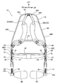
図1~図6を用いて本発明の実施形態に係る前傾姿勢サポート装置について説明する。なお、前傾姿勢サポート装置を装着している状態でかつ直立した状態の使用者から見た前後方向前方側を矢印FRで示し、右側及び左側をそれぞれ矢印RH及び矢印LHで示し、上下方向上側を矢印UPで示す。また、以下の説明で、単に前後、左右、上下の方向を示す場合は、前傾姿勢サポート装置を装着している状態でかつ直立した状態の使用者から見た前後、左右、上下を示すものとする。
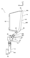
図1~図3に示されるように、本実施形態の前傾姿勢サポート装置10は、人体の腰部の側方側に配置される左右一対のベース部12と、人体の大腿部の側方側に配置される左右一対のスプリングホルダ部14と、人体の上体を支持する上体支持フレーム16と、人体の前傾姿勢をサポートする荷重を発生させる圧縮コイルスプリング18と、圧縮コイルスプリング18の付勢力を上体支持フレームに伝達する左右一対のワイヤ20と、を備えている。
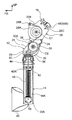
図1及び図4に示されるように、ベース部12は、板状に形成された外側プレート22及び内側プレート24と、を含んで構成されている。外側プレート22と内側プレート24とは、側面視で(右側又は左側から見て)ほぼ同一の形状に形成されている。また、外側プレート22と内側プレート24とは、複数の接続ピン26を介して接続されている。これにより、外側プレート22及び内側プレート24とは、左右方向に所定の間隔を空けてかつ互いに平行に配置されている。
また、外側プレート22と内側プレート24との間には、第1プーリ28及びワイヤガイドとしての第2プーリ30が回転可能に設けられている。図4に示されるように、第1プーリ28は、外側プレート22及び内側プレート24の上部に左右方向を回転軸方向として取付けられており、この第1プーリ28は、円環状に形成されていると共に後述するワイヤ20の一部が巻き付けられる巻付部28Aと、巻付部28Aの径方向外側に向けて延びると共にワイヤ20の一端部20Aが係止されるワイヤ係止部28Bと、を備えている。また、第1プーリ28は、巻付部28Aの径方向外側に向けて延びると共に後述する上体支持フレーム16が固定される上体支持フレーム固定部28Cを備えている。また、第1プーリ28の回転軸は、人体の腰軸に対応する第1軸C1とされている。詳述すると、この第1軸C1は、背骨の最も下の部分である仙骨と仙骨の周囲の寛骨との継ぎ目の部分である仙腸関節に対応している。
第2プーリ30は、外側プレート22及び内側プレート24の下部に左右方向を回転軸方向として取付けられており、この第2プーリ30は、円環状に形成されていると共に後述するワイヤ20の長手方向の中間部をガイドするガイド部30Aを備えている。また、第2プーリ30の回転軸は、人体の脚軸に対応する第2軸C2とされている。この第2軸C2は、人体の股関節に対応しており、また第2軸C2は、側面視で第1軸C1の下方側かつ前方側に配置されている。なお、第2プーリ30の下方側には、一対のガイドローラ32が設けられており、この一対のガイドローラ32の間には、後述するスプリングホルダ部14から引出されたワイヤ20が配置されている。
また、ベース部12の下端部には、後述するスプリングホルダ部14が傾動ブロック44を介して支持されるスプリングホルダ支持部34が固定されている。また、スプリングホルダ支持部34には、ガイドローラ36が取付けられている。そして、スプリングホルダ部14がスプリングホルダ支持部34(ベース部12)に対して傾動された際に、ワイヤ20の一部がガイドローラ36に当接して湾曲されるようになっている。
図1及び図2に示されるように、ベース部12(内側プレート24)における第1軸C1と第2軸C2との間の部位には、左側のベース部12と右側のベース部12とを左右方向に繋ぐと共に、使用者の腰部に装着される腰部ベルト38が挿通される腰部ベルト挿通部40が固定されている。
スプリングホルダ部14は、矩形筒状に形成されている。このスプリングホルダ部14の内部における上方側の部位には、ワイヤ20が挿通されるワイヤ挿通孔42Aが形成された矩形板状のスプリング当接片42が固定されている。また、スプリングホルダ部14の内部においてスプリング当接片42が固定された部位よりも下方側は、圧縮コイルスプリング18が配置される格納部14Aとされている。さらに、スプリングホルダ部14の上端部には、スプリングホルダ支持部34にピンを介して傾動可能に支持される傾動ブロック44が固定されている。この傾動ブロック44の傾動軸(回転軸)の方向は前後方向とされている。これにより、スプリングホルダ部14がベース部12に対して使用者の側方側(右側又は左側)に傾動することが可能となっている。また、スプリングホルダ部14の下端部には、腿パット46が取付けられている。この腿パット46は、使用者の大腿部の前面に沿う湾曲形状とされている。また、腿パット46は、前後方向に傾動可能(左右方向を軸方向として回動可能)とされている。これにより、腿パット46を人体の脚の動きに追従させることが可能となり、その結果、腿パット46と使用者の大腿部の前面との接触状態を所望の接触状態にすることができる。
図1~図3に示されるように、上体支持フレーム16は、正面視で(使用者の正面側から見て)下方側が開放された略U字状に形成されたフレーム本体部48と、フレーム本体部48の下方側の部位を左右方向に繋ぐサブフレーム部50と、を備えている。フレーム本体部48は、人体の肩に対応する部位に沿って左右方向に延びる第1延在部48Aと、第1延在部48Aの右側及び左側の端部からそれぞれ下方側に向けて延びる第2延在部48Bと、を備えている。また、図2に示されるように、第2延在部48Bは、下方側に向かうにつれて使用者の側方側に向けて傾斜されている。これにより、第1延在部48Aと第2延在部48Bの境目の屈曲部48Cが使用者の側方側に突出することが抑制されている。また、フレーム本体部48は、第2延在部48Bの下端部から下方側に向けて延びる第3延在部48Dを備えており、図3に示されるように、この第3延在部48Dは、下方側に向かうにつれて前方に傾斜されている。さらに、第3延在部48Dには、サブフレーム部50が接合されており、また第3延在部48Dの前端部(下端部)は、前述の第1プーリ28の上体支持フレーム固定部28Cに固定されている。これにより、上体支持フレーム16が、ベース部12に取付けられると共に、この上体支持フレーム16が、第1軸C1回りに傾動されるようになっている。
図1に示されるように、上体支持フレーム16のフレーム本体部48には、使用者の上体に装着される上体支持ベルト52がブラケット54,56を介して取付けられている。上体支持ベルト52は、使用者の右肩を支持する右側支持ベルト52Rと、使用者の左肩を支持する左側支持ベルト52Lと、を含んで構成されており、右側支持ベルト52R及び左側支持ベルト52Lの長さはそれぞれ調整可能とされている。
図4及び図5に示されるように、圧縮コイルスプリング18は、スプリングホルダ部14の格納部14A内に格納されており、この圧縮コイルスプリング18は、使用者が直立した状態では自然長となるように、又は、自然長よりもやや圧縮された状態となるように線径及び自然長が設定されている。また、圧縮コイルスプリング18の下端部には、スプリングベース58が係合されている。そして、後述するワイヤ20によってスプリングベース58が上方側へ移動されることで、圧縮コイルスプリング18が当該スプリングベース58とスプリング当接片42との間で圧縮されるようになっている。
図5に示されるように、ワイヤ20は、圧縮コイルスプリング18と上体支持フレーム16との間に設けられている。このワイヤ20の一端部20Aは、前述のスプリングベース58に係止されており、ワイヤ20の他端部20Bは、第1プーリ28のワイヤ係止部28Bに係止されている。また、ワイヤ20の一端部20Aと他端部20Bとの間の部位の下方側は、圧縮コイルスプリング18の径方向内側の空間内に配置されており、ワイヤ20の一端部20Aと他端部20Bとの間の部位の上方側は、第2プーリ30のガイド部30Aに沿って後方側に湾曲されている。そして、ワイヤ20において第2プーリ30のガイド部30Aに沿って後方側に湾曲された部位よりも上方側の部位は、第1プーリ28の巻付部28Aの後方側の部分に沿って配置されている。また、本実施形態では、ワイヤ20において圧縮コイルスプリング18の径方向内側の空間内に配置されている部分の延長上に、第2プーリ30のガイド部30Aの径方向外側の端部が位置するようになっている。これにより、スプリングホルダ部14がベース部12に対して傾動される前の状態では、ワイヤ20の一端部20Aと第2プーリ30との間の部位が屈曲又は湾曲されないようになっている。そして、使用者が前傾姿勢をとる際に、上体支持フレーム16がベース部12に対して傾動されると、ワイヤ20の一部が第1プーリ28の巻付部28Aに巻き取られる。これにより、スプリングベース58が上方側へ移動されて、圧縮コイルスプリング18がスプリングベース58とスプリング当接片42との間で圧縮される。そして、圧縮された圧縮コイルスプリング18の付勢力がワイヤ20及び第1プーリ28を介して上体支持フレーム16に伝達されることで、当該上体支持フレーム16に使用者の上体を引き起こす方向への付勢力が生じるようになっている。
(本実施形態の作用並びに効果)
次に、本実施形態の作用並びに効果について説明する。
次に、本実施形態の作用並びに効果について説明する。
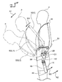
図6に示されるように、本実施形態の前傾姿勢サポート装置10は、腰部ベルト38が使用者Pの腰部に装着されると共に上体支持ベルト52が使用者の上体に装着されて、さらに腿パット46が使用者Pの大腿部に沿って配置されることで、使用者Pに装着される。
ここで、前傾姿勢サポート装置10が使用者Pに装着された状態で、使用者Pの上体が前傾されると、上体支持フレーム16がベース部12に対して第1軸C1回りに傾動される。また、上体支持フレーム16がベース部12に対して傾動されると、ワイヤ20の一部が第1プーリ28の巻付部28Aに巻き取られて(図5参照)、圧縮コイルスプリング18が圧縮される。そして、圧縮された圧縮コイルスプリング18の付勢力がワイヤ20及び第1プーリ28を介して上体支持フレーム16に伝達されることで、当該上体支持フレーム16に使用者の上体を引き起こす方向への付勢力が生じる。そして、この付勢力が上体支持フレーム16を介して使用者Pの上体に入力されることで、前傾姿勢をとっている使用者Pの上体がサポートされる。
また、上体支持フレーム16がベース部12に対して所定の角度だけ傾動されると(上体支持フレーム16が符号Kで示された位置まで傾動されると)、圧縮コイルスプリング18が全圧縮された状態となる。そして、使用者Pの上体が上体支持フレーム16に上体支持ベルト52を介して吊るされた状態とされると、前傾姿勢サポート装置10には矢印A1方向への回転モーメントM1が生じる。また、矢印A1方向への回転モーメントM1が前傾姿勢サポート装置10に生じると、腿パット46が使用者Pの大腿部を押圧する。換言すると、使用者Pの大腿部から前傾姿勢サポート装置10に矢印A1方向への回転モーメントM1を打ち消す方向(矢印A2方向)への回転モーメントM2が入力される。これにより、使用者Pの背部及び腰部に負担を掛けることなく、当該使用者Pの前傾姿勢をサポートすることができる。
また、本実施形態では、上体支持フレーム16を符号Kで示された位置を超えて傾動させることができないようになっている。しかしながら、本実施形態では、上体支持ベルト52の長さを調節することにより、使用者の上体の前傾角度を調節することができる(一例として、符号L1から符号L2で示された前傾角度に調節することができる)。すなわち。本実施形態の前傾姿勢サポート装置10によれば、上体支持フレーム16のベース部12に対する傾動角度を大きく設定しなくても、使用者Pの上体を所望の前傾角度で支持することができる。
ここで、本実施形態では、圧縮コイルスプリング18が圧縮変形されることで、上体支持フレーム16に使用者Pの上体を引き起こす方向への付勢力が生じるように構成されている。そのため、スプリングが引張変形されることで、上体支持フレーム16に使用者の上体を引き起こす方向への付勢力が生じるように構成した場合に比して、スプリング(圧縮コイルスプリング18)及び当該スプリングが配置される格納部14A(スプリングホルダ部14)が大型化することを抑制することができる。これにより、本実施形態では、前傾姿勢サポート装置10の小型化を図ることができる。
また、本実施形態では、左側のベース部12における第1軸C1と第2軸C2間の部位と右側のベース部12における第1軸C1と第2軸C2との間の部位とを繋ぐ腰部ベルト38が使用者Pの腰部に装着される構成とすることにより、前傾姿勢サポート装置10を装着した使用者Pが前傾や歩行する際のフィット感を良好にすることができる。
さらに、本実施形態では、前傾姿勢サポート装置10の使用者Pが脚を開くと、図5に示されるように、スプリングホルダ部14が使用者Pの大腿部に追従してベース部12に対して左右方向に傾動される。これにより、脚を開いた状態での前傾姿勢のサポート性を向上させることができる。
なお、本実施形態では、上体支持ベルト52の長さを調節することにより、使用者の上体の前傾角度を調節することができるように構成した例について説明したが、本発明はこれに限定されない。例えば、上体支持フレーム16のベース部12に対する傾動角度を大きく設定することにより、使用者の上体を所望の前傾角度で支持されるように構成してもよい。
また、本実施形態では、スプリングホルダ部14が使用者Pの大腿部に追従してベース部12に対して左右方向に傾動されるように構成した例について説明したが、本発明はこれに限定されない。スプリングホルダ部14を使用者Pの大腿部に追従してベース部12に対して左右方向に傾動させるか否かについては、前傾姿勢サポート装置10が使用される作業環境等を考慮して適宜設定すればよい。
以上、本発明の一実施形態について説明したが、本発明は、上記に限定されるものでなく、その主旨を逸脱しない範囲内において上記以外にも種々変形して実施することが可能であることは勿論である。
10 上体支持フレーム
12 ベース部
14 スプリングホルダ部
14A 格納部
16 上体支持フレーム
18 圧縮コイルスプリング
20 ワイヤ
30 第2プーリ(ワイヤガイド)
38 腰部ベルト
52 上体支持ベルト
C1 第1軸
C2 第2軸
12 ベース部
14 スプリングホルダ部
14A 格納部
16 上体支持フレーム
18 圧縮コイルスプリング
20 ワイヤ
30 第2プーリ(ワイヤガイド)
38 腰部ベルト
52 上体支持ベルト
C1 第1軸
C2 第2軸
Claims (3)
- 人体の腰軸に対応する第1軸及び人体の脚軸に対応する第2軸を各々備え、前記第2軸の各々の位置にワイヤガイドが設けられた左右一対のベース部と、
左側の前記ベース部における前記第1軸と前記第2軸との間の部位と右側の前記ベース部における前記第1軸と前記第2軸との間の部位とを繋ぎ、人体の腰部に装着される腰部ベルトと、
人体の大腿部の側方側に配置され、かつ左右一対の前記ベース部における前記第2軸側にそれぞれ設けられ、圧縮コイルスプリングが格納される格納部を有する左右一対のスプリングホルダ部と、
左右一対の前記ベース部に取付けられていると共に、人体が前傾することで左右一対の前記ベース部に対して前記第1軸回りに傾動され、人体の上体を支持する上体支持フレームと、
前記圧縮コイルスプリングと前記上体支持フレームとの間に設けられていると共に前記ワイヤガイドにガイドされ、前記上体支持フレームが前記ベース部に対して傾動されることで、前記圧縮コイルスプリングを圧縮させて前記上体支持フレームに人体を引き起こす方向への付勢力を伝達する左右一対のワイヤと、
を備えた前傾姿勢サポート装置。 - 左右一対の前記スプリングホルダ部が、前記ベース部に人体の左右方向に傾動可能に取付けられている請求項1記載の前傾姿勢サポート装置。
- 前記上体支持フレームには、人体の上体に装着される上体支持ベルトが取付けられており、
前記上体支持ベルトの長さが調節されることで、人体の上体の前傾角度が調節される請求項1又は請求項2記載の前傾姿勢サポート装置。
Applications Claiming Priority (2)
| Application Number | Priority Date | Filing Date | Title |
|---|---|---|---|
| JP2015098142A JP6721890B2 (ja) | 2015-05-13 | 2015-05-13 | 前傾姿勢サポート装置 |
| JP2015-098142 | 2015-05-13 |
Publications (1)
| Publication Number | Publication Date |
|---|---|
| WO2016182074A1 true WO2016182074A1 (ja) | 2016-11-17 |
Family
ID=57248893
Family Applications (1)
| Application Number | Title | Priority Date | Filing Date |
|---|---|---|---|
| PCT/JP2016/064351 Ceased WO2016182074A1 (ja) | 2015-05-13 | 2016-05-13 | 前傾姿勢サポート装置 |
Country Status (2)
| Country | Link |
|---|---|
| JP (1) | JP6721890B2 (ja) |
| WO (1) | WO2016182074A1 (ja) |
Cited By (1)
| Publication number | Priority date | Publication date | Assignee | Title |
|---|---|---|---|---|
| CN112975917A (zh) * | 2021-04-20 | 2021-06-18 | 赤源动力(大连)科技有限责任公司 | 腰腹助力外骨骼 |
Families Citing this family (9)
| Publication number | Priority date | Publication date | Assignee | Title |
|---|---|---|---|---|
| JP2018130268A (ja) * | 2017-02-15 | 2018-08-23 | 株式会社イノフィス | 腰部補助装置 |
| US10792209B2 (en) | 2018-02-23 | 2020-10-06 | Lg Electronics Inc. | Wearable assistive device that efficiently delivers assistive force |
| US10603786B2 (en) * | 2018-03-16 | 2020-03-31 | Lg Electronics Inc. | Belt for effective wearing and wearable assistive device having the same |
| KR102061548B1 (ko) * | 2018-04-19 | 2020-01-02 | 근로복지공단 | 작업자용 요추근력보조장치 |
| JP7112969B2 (ja) * | 2019-01-11 | 2022-08-04 | トヨフレックス株式会社 | 動作補助装置 |
| JP7220586B2 (ja) * | 2019-02-27 | 2023-02-10 | トヨフレックス株式会社 | 動作補助装置 |
| KR102157514B1 (ko) * | 2019-03-13 | 2020-09-18 | 국방과학연구소 | 등판 지지 장치 및 이를 포함하는 운동 보조 장치 |
| JP2020193069A (ja) * | 2019-05-28 | 2020-12-03 | 株式会社イノフィス | 腰部補助装置及び腰部補助装置用付勢装置 |
| JP7497317B2 (ja) | 2021-03-17 | 2024-06-10 | 美津濃株式会社 | 装着システム |
Citations (2)
| Publication number | Priority date | Publication date | Assignee | Title |
|---|---|---|---|---|
| WO2010070807A1 (ja) * | 2008-12-17 | 2010-06-24 | 本田技研工業株式会社 | 体重支持装置 |
| WO2011036906A1 (ja) * | 2009-09-28 | 2011-03-31 | 学校法人東京理科大学 | 腰部補助装置 |
Family Cites Families (2)
| Publication number | Priority date | Publication date | Assignee | Title |
|---|---|---|---|---|
| JP5943470B2 (ja) * | 2012-05-15 | 2016-07-05 | 国立大学法人 名古屋工業大学 | 片脚式歩行支援機 |
| JP5210449B1 (ja) * | 2012-11-06 | 2013-06-12 | 勲 河野 | 腰曲がり矯正具 |
-
2015
- 2015-05-13 JP JP2015098142A patent/JP6721890B2/ja active Active
-
2016
- 2016-05-13 WO PCT/JP2016/064351 patent/WO2016182074A1/ja not_active Ceased
Patent Citations (2)
| Publication number | Priority date | Publication date | Assignee | Title |
|---|---|---|---|---|
| WO2010070807A1 (ja) * | 2008-12-17 | 2010-06-24 | 本田技研工業株式会社 | 体重支持装置 |
| WO2011036906A1 (ja) * | 2009-09-28 | 2011-03-31 | 学校法人東京理科大学 | 腰部補助装置 |
Cited By (2)
| Publication number | Priority date | Publication date | Assignee | Title |
|---|---|---|---|---|
| CN112975917A (zh) * | 2021-04-20 | 2021-06-18 | 赤源动力(大连)科技有限责任公司 | 腰腹助力外骨骼 |
| CN112975917B (zh) * | 2021-04-20 | 2025-07-04 | 赤源动力(大连)科技有限责任公司 | 腰腹助力外骨骼 |
Also Published As
| Publication number | Publication date |
|---|---|
| JP2016209443A (ja) | 2016-12-15 |
| JP6721890B2 (ja) | 2020-07-15 |
Similar Documents
| Publication | Publication Date | Title |
|---|---|---|
| WO2016182074A1 (ja) | 前傾姿勢サポート装置 | |
| JP6236162B2 (ja) | 動作支援装置 | |
| JP5526444B2 (ja) | 腰部補助装置 | |
| CN111317971B (zh) | 包含用于执行俯卧曲腿练习的移动支撑件的曲腿练习机器 | |
| EP2913225A1 (en) | Vehicle seat | |
| KR101140009B1 (ko) | 자세 교정용 의자의 서포터 장치 | |
| CN112788965B (zh) | 椅子 | |
| JP7249756B2 (ja) | 腰部補助装置及び腰部補助装置用付勢装置 | |
| WO2018151167A1 (ja) | 腰部補助装置 | |
| JP6283799B1 (ja) | 腰部補助装置 | |
| JP2019022809A (ja) | 椅子式マッサージ機 | |
| EP1747764A3 (en) | Supporting device for a monitor for use in an ultrasonic diagnostic apparatus | |
| JP6635430B2 (ja) | 腿上げサポート装置 | |
| JP2007020909A (ja) | 歩行補助装置 | |
| JP6721318B2 (ja) | 人体サポート装置及び人体サポート装置の使用方法 | |
| CN102984969A (zh) | 椅子 | |
| JP7326116B2 (ja) | 人体サポート装置 | |
| JP6963656B2 (ja) | 引張バネ及び人体サポート装置 | |
| CN103990253A (zh) | 康复设备 | |
| JP2016049210A (ja) | 介助方法及び介助装置 | |
| KR101558412B1 (ko) | 의자 틸팅장치 | |
| WO2018026146A1 (ko) | 휴대용 목 받침대 | |
| JP4387996B2 (ja) | 歩行補助装置 | |
| JP6084891B2 (ja) | 椅子型マッサージ機 | |
| JP2020103574A (ja) | 重量軽減装具 |
Legal Events
| Date | Code | Title | Description |
|---|---|---|---|
| 121 | Ep: the epo has been informed by wipo that ep was designated in this application |
Ref document number: 16792798 Country of ref document: EP Kind code of ref document: A1 |
|
| NENP | Non-entry into the national phase |
Ref country code: DE |
|
| 122 | Ep: pct application non-entry in european phase |
Ref document number: 16792798 Country of ref document: EP Kind code of ref document: A1 |