WO2016181996A1 - スポット溶接方法 - Google Patents
スポット溶接方法 Download PDFInfo
- Publication number
- WO2016181996A1 WO2016181996A1 PCT/JP2016/064019 JP2016064019W WO2016181996A1 WO 2016181996 A1 WO2016181996 A1 WO 2016181996A1 JP 2016064019 W JP2016064019 W JP 2016064019W WO 2016181996 A1 WO2016181996 A1 WO 2016181996A1
- Authority
- WO
- WIPO (PCT)
- Prior art keywords
- welding
- electrode
- metal plate
- normal
- angle
- Prior art date
- Legal status (The legal status is an assumption and is not a legal conclusion. Google has not performed a legal analysis and makes no representation as to the accuracy of the status listed.)
- Ceased
Links
Images


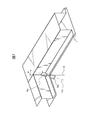


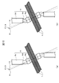

Classifications
-
- B—PERFORMING OPERATIONS; TRANSPORTING
- B23—MACHINE TOOLS; METAL-WORKING NOT OTHERWISE PROVIDED FOR
- B23K—SOLDERING OR UNSOLDERING; WELDING; CLADDING OR PLATING BY SOLDERING OR WELDING; CUTTING BY APPLYING HEAT LOCALLY, e.g. FLAME CUTTING; WORKING BY LASER BEAM
- B23K11/00—Resistance welding; Severing by resistance heating
- B23K11/10—Spot welding; Stitch welding
- B23K11/11—Spot welding
-
- B—PERFORMING OPERATIONS; TRANSPORTING
- B23—MACHINE TOOLS; METAL-WORKING NOT OTHERWISE PROVIDED FOR
- B23K—SOLDERING OR UNSOLDERING; WELDING; CLADDING OR PLATING BY SOLDERING OR WELDING; CUTTING BY APPLYING HEAT LOCALLY, e.g. FLAME CUTTING; WORKING BY LASER BEAM
- B23K11/00—Resistance welding; Severing by resistance heating
- B23K11/16—Resistance welding; Severing by resistance heating taking account of the properties of the material to be welded
-
- B—PERFORMING OPERATIONS; TRANSPORTING
- B23—MACHINE TOOLS; METAL-WORKING NOT OTHERWISE PROVIDED FOR
- B23K—SOLDERING OR UNSOLDERING; WELDING; CLADDING OR PLATING BY SOLDERING OR WELDING; CUTTING BY APPLYING HEAT LOCALLY, e.g. FLAME CUTTING; WORKING BY LASER BEAM
- B23K11/00—Resistance welding; Severing by resistance heating
- B23K11/30—Features relating to electrodes
-
- B—PERFORMING OPERATIONS; TRANSPORTING
- B23—MACHINE TOOLS; METAL-WORKING NOT OTHERWISE PROVIDED FOR
- B23K—SOLDERING OR UNSOLDERING; WELDING; CLADDING OR PLATING BY SOLDERING OR WELDING; CUTTING BY APPLYING HEAT LOCALLY, e.g. FLAME CUTTING; WORKING BY LASER BEAM
- B23K11/00—Resistance welding; Severing by resistance heating
- B23K11/30—Features relating to electrodes
- B23K11/31—Electrode holders and actuating devices therefor
Definitions
- the present invention relates to a spot welding method for a plurality of metal plates including a plated metal plate.
- galvanized steel sheets having excellent corrosion resistance are widely used from the viewpoint of increasing rust prevention of the vehicle body.
- zinc-based plated high-strength steel sheets using high-strength steel sheets as the plating base plates are used in galvanized steel sheets used for automobiles.
- Spot welding is mainly used for the assembly of automobile bodies and parts mounting.
- spot welding is performed on a zinc-based plated high-strength steel plate, there is a problem that cracks occur from the outer surface of the steel plate in contact with the welding electrode toward the nugget.
- FIG. 1 shows an outline of cracks in the welded part when spot welding is performed on a zinc-based plated steel sheet.
- spot welding is performed on the galvanized steel sheet 1
- a crack 3 that progresses from the outer surface of the steel sheet 1 in contact with the electrode toward the nugget 2 and a crack 5 that progresses from the electrode shoulder to the heat affected zone 4 may occur.
- This crack is caused by the applied pressure of the electrode and the thermal stress of the steel sheet, and the tensile stress due to the shrinkage applied to the welded area. It is said to be a crack caused by so-called liquid metal embrittlement caused by lowering the strength.
- the strength decreases when cracks in the welded portion are significant, and a technique for suppressing cracks in the welded portion by controlling the composition and structure of the steel sheet is known.
- Patent Document 1 by adjusting the component composition of the steel sheet, the austenite phase generated at the time of spot welding is made into fine crystal grains, and has a metal structure that is complicated with the crystal grains of other phases.
- a technique has been disclosed in which the diffusion penetration path of molten zinc into the crystal grain boundary is complicated to make it difficult for the molten zinc to enter, thereby preventing liquid metal embrittlement cracking during spot welding.
- the composition of the steel sheet is adjusted and the grain of the hot-rolled steel sheet is adjusted, assuming that the occurrence of cracks in the welded part may not be sufficiently suppressed only by making the grain boundaries complicated by controlling the structure of the steel sheet.
- the grain boundary erosion depth of the alloyed hot-dip galvanized steel sheet should be 5 ⁇ m or less by performing the Fe-based electroplating process on the cold-rolled steel sheet before the alloying hot-dip galvanizing treatment with the field oxidation depth being 5 ⁇ m or less.
- production of the crack in the welding location of a galvannealed steel plate is disclosed.
- Patent Document 3 discloses a technique for removing plating at a butt portion of a strip end portion in order to prevent liquid metal embrittlement when an ERW steel pipe is manufactured from a steel plate plated with zinc or the like. .
- FIG. 2 shows a cross section in the plate thickness direction including the nugget.
- FIG. 2 shows a cross section in the plate thickness direction including the nugget.
- cracks 6 were generated just outside the corona bond on the overlapping surface of the metal plates.
- cracks 7 sometimes occurred during corona bond nuggets.
- the present invention prevents cracks that occur during corona bond nuggets directly outside the corona bond on the overlapping surface of the metal plate in spot welding of a plate assembly including a plated metal plate, It is an object of the present invention to provide a spot welding method capable of forming a high quality spot welded joint.
- the present inventors diligently studied a method for solving the above problems. As a result, the present inventors can weld the contact surface of the electrode tip attached to the tip of the welding electrode even when welding a member having a welding portion where the angle between the electrode axis and the metal plate surface deviates from the vertical. By performing spot welding by adjusting the angle between the normal and the normal of the metal plate surface to be less than 5 degrees, it is possible to prevent cracks directly outside the corona bond and cracks at the corona bond nugget. I found it.
- the present invention has been made on the basis of the above findings, and the gist thereof is as follows.
- a method of spot-welding the overlapped portion of a member having a portion where a plurality of metal plates are overlapped, on the overlapping surface of at least one metal plate among the plurality of metal plates In the above method, the angle between the normal of the contact surface of the electrode tip attached to the tip of the welding electrode and the normal of the metal plate surface is adjusted to less than 5 ° before welding.
- a spot welding method comprising the step of:
- the method of adjusting the angle between the normal of the contact surface of the electrode tip attached to the tip of the welding electrode and the normal of the surface of the metal plate to less than 5 ° includes forming the member.
- the method for adjusting the angle between the normal of the contact surface of the electrode tip attached to the tip of the welding electrode and the normal of the surface of the metal plate to less than 5 ° includes adjustment of the shape of the welding electrode. (1) or (2) the spot welding method.
- the welding electrode includes a holder, a shank assembled to the holder, and an electrode tip attached to the shank.
- the shape of the welding electrode is adjusted by adjusting the holder, the shank, and the electrode.
- the spot welding method according to (3) which is performed by changing one or more shapes of the tip.
- the normal of the contact surface of the electrode tip attached to the tip of the welding electrode, and the normal of the metal plate surface Spot welding is performed with the angle of less than 5 degrees, the residual stress at the outside of the corona bond and at the corona bond nugget is reduced, and the liquid metal cracks at the outside of the corona bond and at the corona bond nugget are reduced. Occurrence can be prevented.
- (A) shows the stress distribution of the whole welding location
- (b) shows the enlarged view of the stress distribution in the vicinity of the corona bond. It is a figure which shows the outline
- (A) shows the welding electrode and metal plate before angle adjustment, and (b) shows the welding electrode and metal plate after angle adjustment. It is a figure which shows the condition which is implementing the welding of the member which has the welding location from which the angle of the axis
- the spot welding method according to the present invention (hereinafter referred to as “the welding method according to the present invention”) is a metal plate of a member including a portion where a plurality of metal plates including one or more metal plates coated with plating are overlapped.
- the overlapped part is a welded part, welding is performed by adjusting the angle between the normal of the contact surface of the electrode tip attached to the tip of the welding electrode and the normal of the surface of the metal plate to be less than 5 degrees. Is to implement.
- the present inventors are concerned with the reason for the occurrence of cracks in the corona bond directly outside and the corona bond nugget that occurs on the inner surface side where the metal plate is superimposed. The following experiment was conducted and investigated.
- Spot welding was performed under various welding conditions using two steel sheets of various component compositions or steel types that were coated with zinc-based plating or not coated with zinc. And the cross section of the plate
- this crack may occur even when a high strength steel plate having a tensile strength of 780 MPa or more and Ceq of 0.15 mass% or more is used. Ceq is shown in the following formula (1).
- Ceq [C] + [Si] / 30 + [Mn] / 20 + 2 [P] +4 [S] (1)
- [C], “Si], [Mn], [P], and [S] are the contents (mass%) of C, Si, P, and S.
- FIG. 3 shows a situation in which spot welding is performed on a member having a welded portion where the angle between the axis of the welding electrode and the surface of the metal plate deviates from vertical during welding.
- the angle ⁇ between the normal 8 of the metal plate 1 and the axis 10 of the welding electrode 9 is 5 degrees or more, cracks immediately outside the corona bond and cracks in the corona bond nugget occurred.
- the angle between the axis of the welding electrode and the direction perpendicular to the metal surface may be expressed as the angle between the axis of the welding electrode and the normal line of the metal plate.
- FIG. 4 shows the stress distribution in the welded portion after welding when there is no strike angle.
- FIG. 5 shows the stress distribution in the welded portion after welding when the striking angle is 5 degrees.
- Fig.5 (a) shows the stress distribution of the whole welding location
- FIG.5 (b) shows the enlarged view of the stress distribution of corona bond right outside.
- FIG. 4 and 5A there is a portion 11 where the welding residual stress is high on the surface of the metal plate 1 in contact with the welding electrodes 9a and 9b.
- FIG. 5 (a) there exists the location 12 (location enclosed with a dotted line) where welding residual stress is high just outside the corona bond of the overlapping surface of a metal plate.
- FIG. 5B shows an enlarged view of the vicinity of the portion 12 where the welding residual stress is high near the outside of the corona bond.
- Such a portion 12 having high welding residual stress in the vicinity of the corona bond directly outside does not occur in the stress distribution of the welded portion after welding when there is no strike angle shown in FIG.
- the portion 12 having a high welding residual stress directly outside the corona bond is in a compressed state in the process of being crushed by the welding electrode during spot welding, but is in a tensile state when the welding electrode is separated, and further in the cooling process after the end of welding.
- FIG. 5 it is considered that the tensile welding residual stress is increased before the zinc-based plated metal is solidified.
- the inventors of the present invention have found that the occurrence of the crack 6 directly outside the corona bond is caused by the fact that the zinc-based plated metal melted directly outside the corona bond has a residual welding stress outside the corona bond after welding. It was inferred that it was caused by intruding into the crystal grain boundary of the metal plate at the high portion 12 and reducing the grain boundary strength.
- ⁇ In spot welding it is basic to apply a spot welding electrode perpendicular to the metal plate surface.
- the electrode shaft and the surface of the metal plate in contact with the electrode such as a place where the space around the welding point is limited and the insertion of the welding gun is difficult, such as a structural member that has already been assembled. Spot welding may occur without being applied vertically.
- the present inventors examined a means for preventing cracks immediately outside the corona bond and cracks in the corona bond nugget. This crack occurs when the normal between the contact surface of the electrode tip attached to the tip of the welding electrode and the normal of the metal plate surface deviates from the vertical, not the angle between the axis of the welding electrode and the metal plate surface. I thought it would happen.
- the present inventors have adjusted the shape so that the angle between the normal of the contact surface of the electrode tip attached to the tip of the welding electrode and the normal of the surface of the metal plate is less than 5 degrees, and spot welding is performed. As a result, it was found that cracks directly outside the corona bond and cracks during corona bond nugget can be prevented.
- the present invention has been made through the above examination process.
- the flow of the welding method of the present invention will be described.
- FIG. 6 is a diagram showing an outline of adjustment of the angle between the normal line of the contact surface of the electrode tip attached to the tip of the welding electrode and the normal line of the metal plate surface.
- FIG. 6A shows the welding electrode and the metal plate before the angle adjustment
- FIG. 6B shows the welding electrode and the metal plate after the angle adjustment
- FIG. 6A shows a case where the angle ⁇ between the normal 8 of the metal plate 1 and the axis 10 of the welding electrodes 9a and 9b is, for example, 5 degrees or more, and this angle is set to be less than 5 degrees.
- the metal plate 1 is fixed, and the welding electrodes 9a and 9b are moved in the direction of the black arrow.
- tip of welding electrode 9a, 9b shall be less than 5 degree
- the welding electrode is moved here, the welding electrode may be fixed and the metal plate may be moved.
- FIG. 7 shows a situation where a member having a welded portion where the angle between the axis of the welding electrode and the surface of the metal plate deviates from the vertical is being welded when the space around the welded portion is limited.
- the pressed portion of the metal plate 1 becomes an obstacle to the angle adjustment, and the movement of at least one of the welding electrodes 9 a and 9 b and the metal plate 1 cannot be sufficiently performed.
- the angle between the normal of the contact surface of the electrode tip attached to the tip of the metal plate and the normal of the surface of the metal plate may not be adjusted to less than 5 degrees.
- FIG. 8 is used to explain an example of adjusting the angle between the normal of the contact surface of the electrode tip attached to the tip of the welding electrode and the normal of the surface of the metal plate when the space around the welding location is limited To do.
- FIG. 8 is a diagram showing an outline of adjustment of the angle between the normal of the contact surface of the electrode tip attached to the tip of the welding electrode and the normal of the surface of the metal plate when the space around the welding location is limited It is.
- FIG. 8A shows the electrode and metal plate for spot welding before angle adjustment
- FIG. 8B shows the electrode and metal plate for spot welding after angle adjustment.
- the angle ⁇ between the normal 8 of the metal plate 1 and the shaft 10 of the welding electrodes 9a and 9b has, for example, 5 degrees or more. Therefore, in order to adjust the angle between the axis of the welding electrode and the surface of the metal plate, the metal plate 1 opposite to the side where the axis 10 of the welding electrode 9a is inclined with respect to the normal 8 of the metal plate 1 is blackened. Pre-shaped and bent in the direction of the arrow. As a result, as shown in FIG. 8B, the angle ⁇ between the normal line 8 of the metal plate 1 at the welding location and the normal line of the contact surface of the electrode tip attached to the tips of the welding electrodes 9a and 9b is less than 5 degrees. And
- the angle between the normal of the contact surface of the electrode tip attached to the tip of the welding electrode and the normal of the metal plate surface is adjusted to be less than 5 degrees.
- the method for adjusting the angle is not particularly limited, but welding is performed so that the angle between the normal of the contact surface of the electrode tip attached to the tip of the welding electrode and the normal of the surface of the metal plate is less than 5 degrees. It can be adjusted by moving the electrode or the metal plate.
- the angle adjustment method is such that the metal plate of the welded portion of the member has an angle between the normal of the contact surface of the electrode tip attached to the tip of the welding electrode and the normal of the surface of the metal plate of less than 5 degrees. You may shape
- the molding position may be at least in a range where spot welding is performed and does not affect the product, and the molding method is not particularly limited.
- the angle By adjusting the angle, if the angle between the normal of the contact surface of the electrode tip attached to the tip of the welding electrode and the normal of the surface of the metal plate is less than 5 degrees, cracks directly outside the corona bond and corona bond nugget Can be prevented from cracking.
- the angle is preferably 4 degrees or less, more preferably 3 degrees or less, still more preferably 2 degrees or less, and most preferably 0 degrees.
- the member to be welded has a portion where a plurality of metal plates are stacked, and the overlapping surface of at least one metal plate among the metal plates is plated.
- the metal plate for example, a steel plate coated with zinc plating and having a tensile strength of 780 MPa or more, Ceq of 0.15 mass% or more, and a plate thickness of 0.5 to 3.0 mm can be used.
- FIG. 9 shows an example of a welding electrode in which the holder shape is adjusted so that the angle between the normal of the contact surface of the electrode tip attached to the tip of the welding electrode and the normal of the metal plate surface is less than 5 degrees from the vertical.
- the welding electrode 9 includes a holder 9c, a shank 9d assembled to the holder 9c, and an electrode tip 9e attached to the shank 9d. Then, by bending the holder 9a, the shape of the welding electrode 9 is adjusted so that the angle between the normal 13 of the contact surface of the electrode tip 9c and the normal 8 of the metal plate is less than 5 degrees.
- the angle between the center axis of the electrode tip and the direction perpendicular to the surface of the metal plate may be described as the angle between the center axis of the electrode tip and the normal line of the metal plate.
- spot welding is performed using a welding gun with such adjusted welding electrodes.
- spot welding two metal plates are overlapped, and the tip is made of a copper alloy or the like so as to sandwich the two metal plates from both sides.
- a molten metal is formed, and the molten metal is rapidly cooled and solidified by heat removal by a water-cooled electrode after conduction and heat conduction to the metal plate itself, and a nugget having an elliptical cross section is formed between the metal plates. .
- the conditions for spot welding at this time are not particularly limited.
- the electrode is a dome radius type tip having a diameter of 6 to 8 mm
- the applied pressure is 150 to 600 kgf
- the energization time is 5 to 50 cycles (power frequency 50 Hz). )
- the welding electrode whose shape is adjusted so that the angle between the normal of the contact surface of the electrode tip attached to the tip of the welding electrode and the normal of the surface of the metal plate is less than 5 degrees will be described.
- the welding electrode is not particularly limited as long as the angle between the normal of the contact surface of the electrode tip attached to the tip of the welding electrode and the normal of the surface of the metal plate is less than 5 degrees. With respect to the welding electrode having this shape adjusted, an example different from FIG. 9 will be described with reference to FIGS.
- FIG. 10 shows another example of the welding electrode in which the shank shape is adjusted so that the angle between the normal of the contact surface of the electrode tip attached to the tip of the welding electrode and the normal of the surface of the metal plate is less than 5 degrees.
- FIG. 10A shows an example in which the shank is bent in one step
- FIG. 10B shows an example in which the shank is bent in two steps.
- FIG. 11 shows another example of the welding electrode in which the shape of the electrode tip is adjusted so that the angle between the center axis of the electrode tip and the surface of the metal plate is less than 5 degrees from the vertical.
- the welding electrode 9 shown in FIGS. 10 and 11 has a holder 9c, a shank 9d, and an electrode tip 9e, like the welding electrode 9 shown in FIG.
- the shape of the welding electrode 9 in FIG. 10 is adjusted by bending the shank 9d so that the angle between the normal 13 of the contact surface of the electrode tip 9e and the normal 8 of the metal plate is less than 5 degrees.
- the bending of the shank 9d may be one step as shown in FIG. 10 (a) or two steps as shown in FIG. 10 (b).
- the holder may be bent in two steps as shown in FIG.
- the shape of the welding electrode 9 is adjusted so that the angle between the normal 13 of the contact surface of the electrode tip 9e and the normal 8 of the metal plate is less than 5 degrees by inclining the tip of the electrode tip 9e. It is adjusted. 9 to 11 show the holder, the shank, or the electrode chip in which the shape is changed, but two or more shapes of the holder, the shank, and the electrode chip may be changed.
- the welding electrode may be movable so that the angle between the normal of the contact surface of the electrode tip attached to the tip of the welding electrode and the normal of the surface of the metal plate can be moved to less than 5 degrees. Moreover, you may perform the change of the shape of a welding electrode, and the change of the shape of the member mentioned above collectively.
- the member is not particularly limited as long as it is composed of a plurality of metal plates on which at least welded portions are overlapped, and the overlapping surface of at least one of the metal plates is coated with plating.
- spot welding is performed with a plurality of steel plates coated with zinc plating on the overlapping surfaces of all spot-welded metal plates or steel plates with zinc-coated plating on the overlapping surfaces of spot-welded steel plates.
- a plurality of steel plates including a steel plate that is not coated with zinc-based plating is exemplified.
- plating is coated on the surface opposite to the overlapping surface of the metal plate to be spot welded, that is, the contact surface with the welding electrode. It may or may not be coated. However, in consideration of the corrosion resistance of the spot welded joint, it is preferable that the contact surface with the welding electrode is also coated with plating.
- the type of plating of the metal plate coated with the plating used in the present invention is not particularly limited.
- the welding method of the present invention is suitable for welding a steel sheet coated with zinc-based plating, but can be similarly applied to other alloy plating such as Al-based plating and Cu-based plating. Further, the present invention can be similarly applied when welding a metal plate other than the plated steel plate.
- each metal plate spot-welded is not particularly limited.
- the welding method of the present invention is suitable for welding steel plates having a plate thickness of 0.5 to 3.0 mm. Further, the overall thickness of the plurality of metal plates is not particularly limited.
- the welding method of the present invention is suitable for welding steel plates having a total plate thickness of 1.0 to 7.0 mm.
- the metal plate may be a plate having at least part of a plate-like portion, and the plate-like portions may be stacked on each other, and the whole may not be a plate.
- the plurality of metal plates are not limited to those composed of separate metal plates, and for example, a single metal plate formed into a predetermined shape such as a tubular shape may be superimposed.
- the metal plate of the member to be spot welded is not particularly limited, such as component composition and metal structure.
- a steel sheet with a zinc-based plating coated on the overlapped surface to be welded, or a steel sheet coated with a zinc-based plating and a steel sheet that is overlapped via a zinc-based plating, TRIP steel sheet or high strength When a steel plate having a Ceq of 0.15% by mass or more is used, cracking is likely to occur immediately outside the corona bond and at the time of the corona bond nugget. May be targeted.
- the plating coated on the metal plate to be welded is not particularly limited, and examples thereof include alloyed hot dip galvanizing, hot dip galvanizing, electrogalvanizing, and zinc / nickel plating. It can also be applied to zinc / aluminum / magnesium plating. Furthermore, it can be applied to aluminum plating and copper plating.
- spot welding may be performed in advance to confirm the occurrence of cracks. There is no problem even if the present invention is applied when no cracks are generated, but if the present invention is applied to the welding position when cracks occur, the effects of the present invention can be obtained efficiently. .
- the electrode may be a dome radius type tip having a diameter of 6 to 8 mm, a pressing force of 150 to 600 kgf, an energization time of 5 to 50 cycles, and an energization current of 4 to 15 kA.
- the method for confirming the occurrence of cracks in the corona bond directly outside and on the corona bond nugget is not particularly limited, and is a method of observing the cross section in the plate thickness direction including the nugget or the tension of the spot welded joint. It is possible to use a method in which a test is performed by determining whether or not a predetermined tensile strength can be obtained. Or, depending on the cutting position of the cross section in the plate thickness direction including the spot welded portion, cracks may not be observed directly outside the corona bond and when corona bond is nuggeted. Also good.
- the object of the present invention is achieved without departing from the gist of the present invention, it can be applied to, for example, iron, aluminum, titanium, and stainless steel other than steel sheets, and composite materials such as metal-resin and dissimilar metals. is there.
- the present invention is not limited to automobiles, and can be applied to members such as various vehicles, general machines, home appliances, and ships as long as spot welding is performed on a metal plate.
- the conditions in the examples are one example of conditions used for confirming the feasibility and effects of the present invention, and the present invention is based on this one example of conditions. It is not limited.
- the present invention can adopt various conditions as long as the object of the present invention is achieved without departing from the gist of the present invention.
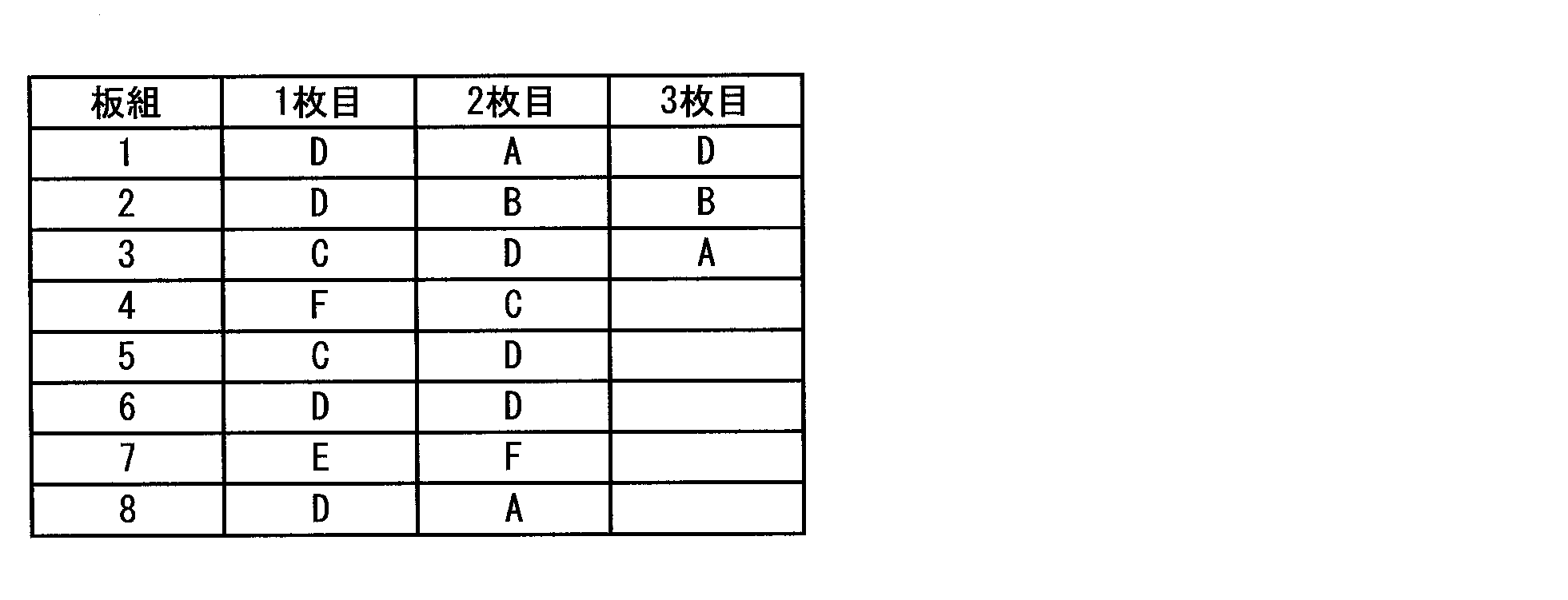
- Example 1 The steel plates with or without zinc plating shown in Table 1 are overlapped with the plate set shown in Table 2, and the overlapped steel plates are sandwiched from both sides with a dome radius type electrode with a tip diameter of 6 mm. While pressing at a pressure of 4 kN, spot welding was performed with an energization time of 18 cycles and an energization current of 9 kA to create a test piece.
- the electrode angle of attack was set to 3 to 10 degrees, and cracks after spot welding were confirmed.
- the crack was confirmed by cutting the test piece in the plate thickness direction so as to include the nugget and confirming the cross section.
- the results are shown in Table 3.
- “ ⁇ ” indicates no crack
- “ ⁇ ” indicates a micro crack of less than 100 ⁇ m
- “ ⁇ ” indicates an internal crack of 100 ⁇ m or more.
- the hitting angle is less than 5 degrees, after spot welding, no cracks of 100 ⁇ m or more occur in all plate assemblies, and the hitting angle is 3 In the case of the degree, no cracks occurred in all the plate assemblies.
- Table 4 shows the metal plates used.
- This metal plate is an alloyed hot-dip galvanized steel plate, and both sides of the high-strength steel plate are coated with galvanizing.
- the galvanized steel sheet A has good corrosion resistance, but cracks were confirmed immediately outside the corona bond and at the time of the corona bond nugget.
- the galvanized steel sheet B had good corrosion resistance, and no cracks were observed on the corona bond directly outside and on the corrugated nugget. The fact that cracking was confirmed in the galvanized steel sheet B is considered to be related to the low C content.
- the cold-rolled steel sheet has poor corrosion resistance, since there is no galvanization, cracks at the corona bond directly outside and at the corona bond nugget were not confirmed.
- plate set of the galvanized steel plate B and the cold rolled steel plate the crack at the time of the corona bond right outside of the cold rolled steel plate and the nugget of the corona bond was confirmed.
- two galvanized steel sheets A in which cracks immediately outside the corona bond and cracks in the corona bond nugget are confirmed are prepared, the two steel sheets are overlapped, and an electrode tip attached to the tip of the welding electrode is prepared.
- Table 5 shows the metal plates subjected to the test.
- This metal plate is an alloyed hot-dip galvanized steel plate, and both sides of the high-strength steel plate are coated with galvanizing.
- Two steel plates shown in Table 5 were prepared, overlapped, sandwiched between welding electrodes, pressed with a pressure of 4 kN, and subjected to spot welding with an energization time of 18 cycles and an energization current of 9 kA to prepare test pieces. Further, as the electrode tip, a copper dome radius type with a tip radius of curvature of 40 (mm) and a tip diameter of 8 (mm) was used. The hitting angle of the welding electrode was 5 degrees.
- the test piece was checked for cracks.
- the crack was confirmed by cutting the test piece in the plate thickness direction so as to include the nugget and confirming the cross section. As a result, cracks were observed immediately outside the corona bond and at the time of corona bond nugget.
- a welding electrode whose shape was adjusted so that the angle between the normal of the contact surface of the electrode tip attached to the tip of the welding electrode and the normal of the steel plate surface was less than 5 degrees was prepared. Specifically, a welding electrode having an adjusted holder shape shown in FIG. 9, a welding electrode having an adjusted shank shape shown in FIG. 10A, and a welding electrode having an adjusted electrode tip shape shown in FIG. 11 were prepared.
- spot welding is performed with an angle between the normal of the contact surface of the electrode tip attached to the tip of the welding electrode and the normal of the surface of the metal plate being less than 5 degrees. Residual stress at the time of nugget of the bond becomes low, and occurrence of liquid metal cracking can be prevented immediately outside the corona bond and at the time of corona bond nugget. Therefore, the present invention has high industrial applicability.
Landscapes
- Engineering & Computer Science (AREA)
- Mechanical Engineering (AREA)
- Resistance Welding (AREA)
Abstract
めっきされた金属板(1)を含む板組のスポット溶接における、金属板(1)の重ね合わせ面のコロナボンド直外及びコロナボンドのナゲット際に発生する割れ(6,7)を防止し、高品質のスポット溶接継手を形成できるスポット溶接方法であって、溶接を実施する前に、溶接電極(9)の先端に取り付けられる電極チップ(9e)の中心軸(10)と上記電極チップ(9e)に接触する上記金属板表面の法線(8)との角度を垂直から5°未満に調節することを特徴とする。
Description
本発明は、めっきされた金属板を含む複数枚の金属板のスポット溶接方法に関する。
自動車用の部材としては、車体の高防錆化の観点から、耐食性に優れた亜鉛系めっき鋼板が広く用いられる。軽量化や高強度化の観点から、自動車用として用いられる亜鉛系めっき鋼板においては、めっき原板に高強度鋼板を用いた亜鉛系めっき高強度鋼板が使用される。
自動車の車体の組立や部品の取付け等では、主として、スポット溶接が使われている。しかしながら、亜鉛系めっき高強度鋼板にスポット溶接を行うと、溶接電極と接する鋼板の外側面から、ナゲットに向かって、割れが発生するという問題がある。
図1に、亜鉛系めっき鋼板にスポット溶接を行った場合の溶接箇所の割れの概略を示す。亜鉛系めっき鋼板1にスポット溶接を行うと、電極と接する鋼板1の外側面からナゲット2に向かって進展する割れ3や、電極肩部から熱影響部4に進展する割れ5が発生することが知られている。
この割れは、電極の加圧力や鋼板の熱膨張、収縮による引張応力が溶接箇所に加わり、溶接箇所の鋼板表面で溶融した亜鉛や、亜鉛や電極の銅等が、鋼板に侵入して粒界強度を低下させて引き起こされる、いわゆる液体金属脆性に起因する割れであるといわれている。自動車車体では、溶接箇所の割れが著しいと強度が低下するという問題があり、鋼板の成分組成や組織を制御することにより、溶接箇所の割れを抑制する技術が知られている。
特許文献1には、鋼板の成分組成を調整し、スポット溶接時に生成されるオーステナイト相を微細な結晶粒にして、他の相の結晶粒と複雑に入り組んだ金属組織を有するものとすることで、結晶粒界への溶融亜鉛の拡散浸入経路を複雑にして、溶融亜鉛を侵入し難くして、スポット溶接時の液体金属脆化割れを防止する技術が開示されている。
特許文献2には、鋼板の組織制御によって結晶粒界を複雑化するだけでは、溶接部の割れ発生を充分に抑制できないことがあるとして、鋼板の成分組成を調整し、熱間圧延鋼板の粒界酸化深さを5μm以下とし、合金化溶融亜鉛めっき処理前の冷間圧延鋼板にFe系電気めっき処理を行うことによって、合金化溶融亜鉛めっき鋼板の粒界侵食深さを5μm以下にすることで、合金化溶融亜鉛めっき鋼板の溶接箇所における割れの発生を抑制する技術が開示されている。
特許文献3には、亜鉛等のめっきを施した鋼板から電縫鋼管を製造する際に、液体金属脆化防止のために、ストリップ端部の突合せ部のめっきを除去する技術が開示されている。
このようにスポット溶接箇所の割れの対策は検討されているものの、めっきされた金属板のスポット溶接継手において、又は一部の非めっき金属板とめっきされた金属板のスポット溶接継手において、依然として、所望の引張強度が得られないことがあった。
本発明者らは、この理由について調査した。図2に、ナゲットを含む板厚方向の断面を示す。図2に示すように、所望の引張強度が得られないスポット溶接継手には、金属板の重ね合わせ面のコロナボンド直外に割れ6が生じていた。また、コロナボンドのナゲット際に割れ7が生じていることもあった。
本発明は、このような実情に鑑み、めっきされた金属板を含む板組のスポット溶接における、金属板の重ね合わせ面のコロナボンド直外及びコロナボンドのナゲット際に発生する割れを防止し、高品質のスポット溶接継手を形成できるスポット溶接方法を提供することを課題とする。
本発明者らは、前記課題を解決する方法について鋭意検討した。その結果、本発明者らは、電極の軸と金属板表面との角度が垂直から外れる溶接箇所を有する部材を溶接する場合であっても、溶接電極の先端に取り付けられる電極チップの接触面の法線と、金属板表面の法線との角度が5度未満となるように調整してスポット溶接を実施することにより、コロナボンド直外の割れ及びコロナボンドのナゲット際の割れを防止できることを見出した。
本発明は、上記知見に基づいてなされたもので、その要旨とするところは以下のとおりである。
(1)複数の金属板が重ね合わせられた箇所を有する部材の上記重ね合わせられた箇所をスポット溶接する方法であって、上記複数の金属板のうち少なくとも1枚の金属板の重ね合わせ面にめっきが施されており、上記方法は、溶接を実施する前に、溶接電極の先端に取り付けられる電極チップの接触面の法線と、金属板表面の法線との角度を5°未満に調節する工程を含むことを特徴とするスポット溶接方法。
(2)前記溶接電極の先端に取り付けられる電極チップの接触面の法線と、前記金属板表面の法線との角度を5°未満に調節する方法は、前記部材の成形を含むことを特徴とする前記(1)のスポット溶接方法。
(3)前記溶接電極の先端に取り付けられる電極チップの接触面の法線と、前記金属板表面の法線との角度を5°未満に調節する方法は、溶接電極の形状の調整を含むことを特徴とする前記(1)又は(2)のスポット溶接方法。
(4)前記溶接電極は、ホルダーと、上記ホルダーに組みつけられたシャンクと、上記シャンクに取り付けられた電極チップを備え、前記溶接電極の形状の調整は、上記ホルダー、上記シャンク、及び上記電極チップの1又は2以上の形状を変更することにより行う
ことを特徴とする前記(3)のスポット溶接方法。
ことを特徴とする前記(3)のスポット溶接方法。
(5)前記複数の金属板のうち少なくとも1枚の金属板が亜鉛めっき鋼板であることを特徴とする前記(1)~(4)のいずれかのスポット溶接方法。
本発明によれば、電極の軸と金属板表面との角度が垂直から外れる場合であっても、溶接電極の先端に取り付けられる電極チップの接触面の法線と、金属板表面の法線との角度が5度未満となるようにしてスポット溶接が行われるので、コロナボンド直外及びコロナボンドのナゲット際の残留応力が低くなり、コロナボンド直外及びコロナボンドのナゲット際において液体金属割れの発生を防ぐことができる。
本発明のスポット溶接方法(以下「本発明の溶接法」という)は、めっきが被覆されている金属板を1枚以上含む複数枚の金属板が重ね合わされた箇所を含む部材の、金属板が重ね合わされた箇所を溶接箇所とする場合に、溶接電極の先端に取り付けられる電極チップの接触面の法線と、金属板表面の法線との角度が5度未満となるように調整して溶接を実施するものである。
以下、本発明の溶接法に至った検討の経緯、及び本発明の溶接法について詳細に説明する。
本発明者らは、亜鉛系めっき鋼板を用いて、めっきされた金属板のスポット溶接において、金属板が重ね合わされた内面側で生じるコロナボンド直外及びコロナボンドのナゲット際の割れの発生理由について次のような実験を行い、調査した。
亜鉛系めっきが被覆された、及びめっきが被覆されていない、種々の成分組成又は鋼種の鋼板を2枚用いて、種々の溶接条件でスポット溶接を行った。そして、得られたスポット溶接継手のうち、引張強度が低くなるスポット溶接継手のナゲットを含む板厚方向の断面を観察した。
その結果、鋼板の重ね合わせ面のコロナボンド直外の割れ及びコロナボンドのナゲット際の割れは、合金成分を多く含む加工誘起マルテンサイト相変態を利用した、いわゆるTRIP鋼を用いた場合に生じ、合金成分が少なくフェライト相とマルテンサイト相を複合させた、いわゆるDP鋼を用いた場合には生じ難くかった。
また、この割れは、引張強度が780MPa以上で、Ceqが0.15質量%以上の高強度鋼板を用いた場合にも発生することがあった。なお、Ceqは下記(1)式に示すものである。
Ceq=[C]+[Si]/30+[Mn]/20+2[P]+4[S]・・・(1)
ただし、[C]、「Si]、[Mn]、[P]、[S]は、C、Si、P、及びSの含有量(質量%)である。
ただし、[C]、「Si]、[Mn]、[P]、[S]は、C、Si、P、及びSの含有量(質量%)である。
また、この割れが発生するスポット溶接の際の鋼板態様としては、2枚の鋼板同士が隙間を有するように重ね合わされているものにスポット溶接した場合に生じることがあった。
図3は、溶接の際に、溶接電極の軸と、金属板表面との角度が垂直から外れる溶接箇所を有する部材のスポット溶接を実施している状況を示している。図3のように、金属板1の法線8と溶接電極9の軸10の角度θが5度以上の場合に、特にコロナボンド直外の割れ及びコロナボンドのナゲット際の割れが発生した。以下、溶接電極の軸と、金属表面に対して垂直方向との角度を、溶接電極の軸と、金属板の法線との角度と表現して説明することがある。
溶接後のスポット溶接箇所をモデル化し、応力分布のFEM解析(有限要素法解析)を行った。まず、溶接電極の軸と金属板表面とが垂直の場合(打角の無い場合)と、溶接電極の軸と金属板表面とが垂直から5度の角度の場合(打角が5度の場合)のスポット溶接後の溶接箇所の応力分布を計算により求めた。図4に、打角の無い場合の溶接後の溶接箇所の応力分布を示す。図5に、打角が5度の場合の溶接後の溶接箇所の応力分布を示す。図5(a)は、溶接箇所全体の応力分布を示し、図5(b)はコロナボンド直外近傍の応力分布の拡大図を示す。
図4及び図5(a)では、両者とも溶接電極9a、9bと接触した金属板1の表面に溶接残留応力が高い箇所11がある。また、図5(a)には、金属板の重ね合わせ面のコロナボンド直外に溶接残留応力が高い箇所12(点線で囲まれる箇所)がある。図5(b)には、このコロナボンド直外近傍の溶接残留応力の高い箇所12の近傍部分の拡大図を示している。このようなコロナボンド直外近傍の溶接残留応力の高い箇所12は、図4に示す打角の無い場合の溶接後の溶接箇所の応力分布には生じなかった。
コロナボンド直外の溶接残留応力が高い箇所12は、スポット溶接の際に溶接電極により押しつぶされる過程で圧縮状態にあるが、溶接電極が離れると引張り状態になり、さらに溶接終了後の冷却過程において、亜鉛系めっき金属が凝固する前に、図5に示すように、引張の溶接残留応力が高くなると考えられる。これより、本発明者らは、コロナボンド直外の割れ6の発生は、スポット溶接の過程において、コロナボンド直外で溶融した亜鉛系めっき金属が、溶接後にコロナボンド直外の溶接残留応力が高い箇所12の金属板の結晶粒界に侵入して、粒界強度を低下させることにより引き起こされると推察した。
また、コロナボンドの発達が不十分な場合には、コロナボンドのナゲット際に溶接残留応力が高い箇所(図示せず)が発生し、ナゲット形成位置から溶融排除された亜鉛系めっき金属が、コロナボンドのナゲット際の残留応力の高い箇所の金属板の結晶粒界に侵入して、粒界強度を低下させることによりコロナボンドのナゲット際の割れが引き起こされると推察した。
スポット溶接においては、金属板表面に対してスポット溶接用の電極を垂直に当てるのが基本である。しかしながら、たとえば自動車の組立において、すでに組み上がった構造部材のように溶接箇所の周囲のスペースに制限があり溶接ガンの挿入が困難な箇所等、電極の軸と電極に接触する金属板表面とを垂直に当てずにスポット溶接することがある。
本発明者らは、このような場合において、コロナボンド直外の割れ及びコロナボンドのナゲット際の割れの防止手段について検討した。この割れは、溶接電極の軸と金属板表面との角度ではなく、溶接電極の先端に取り付けられる電極チップの接触面の法線と、金属板表面の法線との角度が垂直から外れる場合に発生すると考えた。
そこで、本発明者らは、溶接電極の先端に取り付けられる電極チップの接触面の法線と、金属板表面の法線との角度が5度未満となるように形状を調整し、スポット溶接を実施したところ、コロナボンド直外の割れ及びコロナボンドのナゲット際の割れを防止できることを見出した。
本発明は、以上のような検討過程を経てなされたものである。以下、本発明の溶接法の流れについて説明する。
図6を用いて、溶接電極の先端に取り付けられる電極チップの接触面の法線と、金属板表面の法線との角度の調整の一例を説明する。図6は、溶接電極の先端に取り付けられる電極チップの接触面の法線と、金属板表面の法線との角度の調整の概要を示す図である。
図6(a)に、角度調整前の溶接電極と金属板を示し、図6(b)に、角度調整後の溶接電極と金属板を示す。図6(a)は、金属板1の法線8と溶接電極9a、9bの軸10の角度θが、たとえば、5度以上有している場合であり、この角度を5度未満とするために、金属板1を固定して、溶接電極9a、9bを黒矢印の方向に移動する。これにより、図6(b)に示すように、金属板1の法線8と溶接電極9a、9bの先端に取り付けられる電極チップの接触面の法線の角度θを5度未満とする。ここでは、溶接電極を移動させたが、溶接電極を固定して、金属板を移動させてもよい。
図7は、溶接箇所の周囲のスペースに制限がある場合に、溶接電極の軸と、金属板表面との角度が垂直から外れる溶接箇所を有する部材の溶接を実施している状況を示す。図7のような場合、金属板1のプレス加工などされた部分が角度調整に対して障害となり、溶接電極9a、9b及び金属板1の少なくとも一方の移動を十分することができず、溶接電極の先端に取り付けられる電極チップの接触面の法線と、金属板表面の法線との角度を5度未満に調整することができないことがある。
図8を用いて、溶接箇所の周囲のスペースに制限がある場合の溶接電極の先端に取り付けられる電極チップの接触面の法線と、金属板表面の法線との角度の調整の一例を説明する。
図8は、溶接箇所の周囲のスペースに制限がある場合に、溶接電極の先端に取り付けられる電極チップの接触面の法線と、金属板表面の法線との角度の調整の概要を示す図である。図8(a)に、角度調整前のスポット溶接用の電極と金属板を示し、図8(b)に、角度調整後のスポット溶接用の電極と金属板を示す。
図8(a)では、金属板1の法線8と溶接電極9a、9bの軸10の角度θが、たとえば、5度以上有している。そこで、溶接電極の軸と金属板表面との角度調整するために、金属板1の法線8に対して、溶接電極9aの軸10が傾斜している側と反対側の金属板1を黒矢印の方向に凸状に予め成形して曲げる。これにより、図8(b)に示すように、溶接箇所の金属板1の法線8と溶接電極9a、9bの先端に取り付けられる電極チップの接触面の法線との角度θを5度未満とする。
(溶接電極と金属板の角度調整)
本発明のスポット溶接方法では、溶接電極の先端に取り付けられる電極チップの接触面の法線と、金属板表面の法線との角度が5度未満となるように調整する。角度調整の方法は、特に限定されるものでないが、溶接電極の先端に取り付けられる電極チップの接触面の法線と、金属板表面の法線との角度が5度未満となるように、溶接電極又は金属板を移動させて調整することができる。
本発明のスポット溶接方法では、溶接電極の先端に取り付けられる電極チップの接触面の法線と、金属板表面の法線との角度が5度未満となるように調整する。角度調整の方法は、特に限定されるものでないが、溶接電極の先端に取り付けられる電極チップの接触面の法線と、金属板表面の法線との角度が5度未満となるように、溶接電極又は金属板を移動させて調整することができる。
また、溶接箇所の周囲のスペースに制限があり、溶接の際に、溶接電極又は金属板を移動させて角度調整することができない場合もある。その際の角度調整の方法は、部材のうち溶接箇所の金属板を、溶接電極の先端に取り付けられる電極チップの接触面の法線と、金属板表面の法線との角度が5度未満となるように成形してもよい。成形位置は、少なくともスポット溶接される範囲で、製品に影響がない範囲に対して行えばよく、また、成形方法は特に限定されない。
角度調整により、溶接電極の先端に取り付けられる電極チップの接触面の法線と、金属板表面の法線との角度を5度未満とすれば、コロナボンド直外の割れ及びコロナボンドのナゲット際の割れを抑制できる。上記角度は好ましくは4度以下、より好ましくは3度以下、さらに好ましくは2度以下であり、0度であれば最も好ましい。
次に、溶接電極の先端に取り付けられる電極チップの接触面の法線と、金属板表面の法線との角度が5度未満となるように溶接電極の形状を調整し、溶接電極の先端に取り付けられる電極チップの接触面の法線と、金属板表面の法線との角度を5度未満に調節する方法について説明する。
溶接される部材は複数の金属板が重ねられた箇所を備え、金属板のうち少なくとも1枚の金属板の重ね合わせ面にめっきはめっきが施されている。金属板としては、たとえば、亜鉛系めっきが被覆された、引張強度780MPa以上、Ceqが0.15質量%以上、板厚0.5~3.0mmの鋼板を用いることができる。
スポット溶接において、溶接電極の軸と電極に接触する金属板表面との角度が垂直から外れる溶接箇所があるとき、溶接電極の先端に取り付けられる電極チップの接触面の法線と、金属板表面の法線との角度が5度未満となるように形状を調整した溶接電極を溶接ガンに取り付ける。
図9に、溶接電極の先端に取り付けられる電極チップの接触面の法線と、金属板表面の法線との角度が垂直から5度未満となるようにホルダー形状を調整した溶接電極の一例を示す。溶接電極9は、ホルダー9cと、ホルダー9cに組みつけられたシャンク9dと、シャンク9dに取り付けられた電極チップ9eを有する。そして、ホルダー9aを屈曲させることで、電極チップ9cの接触面の法線13と、金属板の法線8との角度を5度未満となるように溶接電極9の形状が調整されている。以下、電極チップの中心軸と、金属板表面に対して垂直方向との角度を、電極チップの中心軸と、金属板の法線との角度と表現して説明することがある。
次に、このような調整された溶接電極を取り付けた溶接ガンを用いてスポット溶接を行う。スポット溶接では、2枚の金属板を重ね合わせて、両側から2枚の金属板を挟み込むように、先端が銅合金等からなり、前記の形状が調整された溶接電極を押し付けつつ通電して、溶融金属を形成し、通電の終了後に水冷された電極による抜熱や金属板自体への熱伝導によって、溶融金属を急速に冷却して凝固させ、金属板の間に、断面楕円形状のナゲットを形成する。
この際のスポット溶接の条件は、特に限定されるものでなく、たとえば、電極をドームラジアス型の先端直径6~8mmのものとし、加圧力150~600kgf、通電時間5~50サイクル(電源周波数50Hz)、通電電流4~15kAとする。これにより、コロナボンド直外及びコロナボンドのナゲット際において液体金属割れの発生を防ぐことができる。
溶接法について、さらに、必要な要件や好ましい要件について順次説明する。
まず、溶接電極の先端に取り付けられる電極チップの接触面の法線と、金属板表面の法線との角度が5度未満となるように形状を調整した溶接電極について説明する。
(溶接電極)
溶接電極は、溶接電極の先端に取り付けられる電極チップの接触面の法線と、金属板表面の法線との角度が5度未満となる形状であれば、特に限定されるものでない。この形状が調整された溶接電極について、図9とは異なる例について、図10及び図11を用いて説明する。
溶接電極は、溶接電極の先端に取り付けられる電極チップの接触面の法線と、金属板表面の法線との角度が5度未満となる形状であれば、特に限定されるものでない。この形状が調整された溶接電極について、図9とは異なる例について、図10及び図11を用いて説明する。
図10に、溶接電極の先端に取り付けられる電極チップの接触面の法線と、金属板表面の法線との角度が5度未満となるようにシャンク形状を調整した溶接電極の他の例を示す。図10(a)は、シャンクの屈曲を1段とした例を示し、図10(b)は、シャンクの屈曲を2段とした例を示す。また、図11に、電極チップの中心軸と、金属板表面との角度が垂直から5度未満となるように電極チップ形状を調整した溶接電極の他の例を示す。
図10及び図11に示す溶接電極9は、図9に示す溶接電極9と同様に、ホルダー9cと、シャンク9dと、電極チップ9eを有する。そして、図10の溶接電極9は、シャンク9dを屈曲させることで、電極チップ9eの接触面の法線13と、金属板の法線8との角度が5度未満となるように形状が調整されている。シャンク9dの屈曲は、図10(a)に示すように1段でも、図10(b)に示すように2段でもよい。また、図9に示す溶接電極において、ホルダーの屈曲を図10(b)のように2段としてもよい。
図11では、電極チップ9eの先端を傾斜させることで、電極チップ9eの接触面の法線13と、金属板の法線8との角度を5度未満となるように溶接電極9の形状を調整している。図9~図11では、ホルダー、シャンク、又は、電極チップのいずれかの形状を変更したものを示したが、ホルダー、シャンク、及び、電極チップの2以上の形状を変更したものとしてもよい。
さらに、溶接電極を可動とし、溶接電極の先端に取り付けられる電極チップの接触面の法線と、金属板表面の法線との角度を5度未満となるように動かせるようにしてもよい。また、溶接電極の形状の変更と、上述した部材の形状の変更を併せて行ってもよい。
(部材)
次に、スポット溶接される部材について説明する。
次に、スポット溶接される部材について説明する。
部材は、少なくとも溶接箇所が重ね合わされた複数枚の金属板で構成され、そのうちの少なくとも1枚以上の金属板の重ね合わせ面にめっきが被覆されていれば、特に限定されない。たとえば、全てのスポット溶接される金属板の重ね合わせ面に亜鉛系めっきが被覆された複数枚の鋼板や、スポット溶接される鋼板の重ね合わせ面に亜鉛系めっきが被覆された鋼板とスポット溶接される鋼板に亜鉛系めっきが被覆されていない鋼板を含む複数枚の鋼板等が例示される。
また、スポット溶接される重ね合わせ面にめっきが被覆された金属板において、スポット溶接される金属板の重ね合わせ面と反対側の面、つまり、溶接電極との接触面には、めっきが、被覆されていても、被覆されていなくもよい。ただし、スポット溶接継手の耐食性を考慮すれば、溶接電極との接触面にもめっきが被覆されていることが好ましい。
本発明に使用されるめっきが被覆された金属板のめっきの種類は特に限定されない。本発明の溶接方法は亜鉛系めっきが被覆された鋼板の溶接に好適であるが、Al系めっき、Cu系めっき等その他の合金めっきの場合でも同様に適用できる。また、めっきされた鋼板以外の金属板を溶接する場合でも同様に適用できる。
スポット溶接される複数枚の金属板として、図9~11では、2枚の金属板を記載しているが、接合する構造部品の形態に応じて、3枚以上の複数枚の金属板とすることができる。スポット溶接される各金属板の板厚は、特に限定されるものでない。本発明の溶接方法は、板厚が0.5~3.0mmの鋼板の溶接に好適である。また、複数枚の金属板の全体の板厚も、特に限定されるものでない。本発明の溶接方法は、全体の板厚が1.0~7.0mmの鋼板の溶接に好適である。
また、金属板は、少なくとも一部に板状部を有し、板状部が互いに積み重ね合わされる部分を有するものであればよく、全体が板でなくともよい。また、複数枚の金属板は、別々の金属板から構成されるものに限定されず、たとえば、1枚の金属板を管状等の所定の形状に成形したものを重ね合わせたものでもよい。
また、スポット溶接される部材の金属板は、成分組成や、金属組織等、特に限定されるものでない。ただし、溶接される重ね合わせ面に亜鉛系めっきが被覆された鋼板、又は、亜鉛系めっきが被覆された鋼板と亜鉛系めっきを介して重ね合わされている鋼板に対して、TRIP鋼板や、高強度鋼板でCeqが0.15質量%以上の鋼板を用いたときに、コロナボンド直外及びコロナボンドのナゲット際での割れが発生しやすいため、本発明の溶接法において、特に、このような鋼板を対象としてもよい。
また、溶接される金属板に被覆されるめっきは特に限定するものでなく、たとえば、合金化溶融亜鉛めっき、溶融亜鉛めっき、電気亜鉛めっき、亜鉛・ニッケルめっきが例示される。また、亜鉛・アルミニウム・マグネシウム系のめっきにも適用できる。さらに、アルミニウムのめっきや銅めっきにも適用できる。
(割れの確認)
本発明のスポット溶接方法を適用する前に、あらかじめスポット溶接を行い、割れの発生を確認してもよい。割れの発生がない場合に本発明を適用しても問題はないが、割れが発生した際にその溶接位置に対して本発明を適用すれば、効率的に本発明の効果を得ることができる。
本発明のスポット溶接方法を適用する前に、あらかじめスポット溶接を行い、割れの発生を確認してもよい。割れの発生がない場合に本発明を適用しても問題はないが、割れが発生した際にその溶接位置に対して本発明を適用すれば、効率的に本発明の効果を得ることができる。
溶接電極の軸と、金属板表面との角度が垂直から外れる溶接箇所を有する部材を溶接する場合には、あらかじめスポット溶接を行うのがよい。特に、溶接電極の軸と、金属板表面とが垂直から5度以上(打角が5度以上)となる溶接箇所を溶接する場合、コロナボンド直外やコロナボンドのナゲット側の割れが発生しやすいため、あらかじめスポット溶接を行い、割れの発生の有無を確認するとよい。
あらかじめ行う部材へのスポット溶接は、溶接電極の軸が、電極に接触する金属板表面と垂直から外れた状態で、部材に溶接を行う。その際の溶接条件は特に限定されるものでなく、通常の溶接条件を採用することができる。たとえば、電極をドームラジアス型の先端直径6~8mmのものとし、加圧力150~600kgf、通電時間5~50サイクル、通電電流4~15kAとすることができる。
(コロナボンド直外及びコロナボンドのナゲット際の割れの確認)
あらかじめ行うスポット溶接によって、得られたスポット溶接継手のコロナボンド直外及びコロナボンドのナゲット際の割れの発生の有無を確認する。コロナボンド直外及びコロナボンドのナゲット際の割れの発生の有無の確認方法は、特に限定されるものでなく、ナゲットを含む板厚方向の断面を観察して行う方法や、スポット溶接継手の引張試験を実施して所定の引張強度が得られるか否かで判定して行う方法を用いることができる。または、スポット溶接部を含む板厚方向の断面の切断位置によっては、コロナボンド直外及びコロナボンドのナゲット際の割れが観察できない場合もあるため、X線透過試験を行って割れを確認してもよい。
あらかじめ行うスポット溶接によって、得られたスポット溶接継手のコロナボンド直外及びコロナボンドのナゲット際の割れの発生の有無を確認する。コロナボンド直外及びコロナボンドのナゲット際の割れの発生の有無の確認方法は、特に限定されるものでなく、ナゲットを含む板厚方向の断面を観察して行う方法や、スポット溶接継手の引張試験を実施して所定の引張強度が得られるか否かで判定して行う方法を用いることができる。または、スポット溶接部を含む板厚方向の断面の切断位置によっては、コロナボンド直外及びコロナボンドのナゲット際の割れが観察できない場合もあるため、X線透過試験を行って割れを確認してもよい。
コロナボンド直外及びコロナボンドのナゲット際の割れは、めっきが被覆された金属板の重ね合わせ面、又はめっきが被覆された金属板とめっきを介して重ね合わされている金属板の面に発生する。そして、これらの金属板の面のうち、コロナボンド内及びその近傍に発生する。コロナボンド内及びその近傍とは、金属板の面のうち、コロナボンドのナゲット側端部から、コロナボンド直径Dcのおよそ1.2倍の範囲までのことである。
なお、上記の説明は、自動車用の亜鉛めっき鋼板を中心に行ったが、本発明はこれに限定されるものではない。本発明の要旨を逸脱せず、本発明の目的を達成する限りにおいては、たとえば、鋼板以外の鉄、アルミ、チタン、及びステンレス、並びに金属-樹脂、異種金属等の複合材料にも適用可能である。また、自動車用に限定されるものでもなく、金属板にスポット溶接を行うものであれば、各種車両、一般機械、家電、船舶等の部材にも適用可能である。
次に、本発明の実施例について説明するが、実施例での条件は、本発明の実施可能性及び効果を確認するために採用した一条件例であり、本発明は、この一条件例に限定されるものではない。本発明は、本発明の要旨を逸脱せず、本発明の目的を達成する限りにおいて、種々の条件を採用し得るものである。
[実施例1]
表1に示す、亜鉛系めっきが施された、あるいはめっきされていない鋼板を、表2に示す板組で重ねあわせ、両側から、先端直径6mmのドームラジアス型電極で、重ねあわせた鋼板を挟み込み、加圧力4kNで押し付けつつ、通電時間18サイクル、通電電流9kAとして、スポット溶接を行い、試験片を作成した。
表1に示す、亜鉛系めっきが施された、あるいはめっきされていない鋼板を、表2に示す板組で重ねあわせ、両側から、先端直径6mmのドームラジアス型電極で、重ねあわせた鋼板を挟み込み、加圧力4kNで押し付けつつ、通電時間18サイクル、通電電流9kAとして、スポット溶接を行い、試験片を作成した。

電極の打角を3~10度とし、スポット溶接後の割れを確認した。割れの確認は、ナゲットを含むように、試験片を板厚方向に切断して、その断面を確認して行った。結果を表3に示す。表3の「◎」は割れなし、「○」は100μm未満の微小な割れあり、「×」は100μm以上の内割れありを示す。
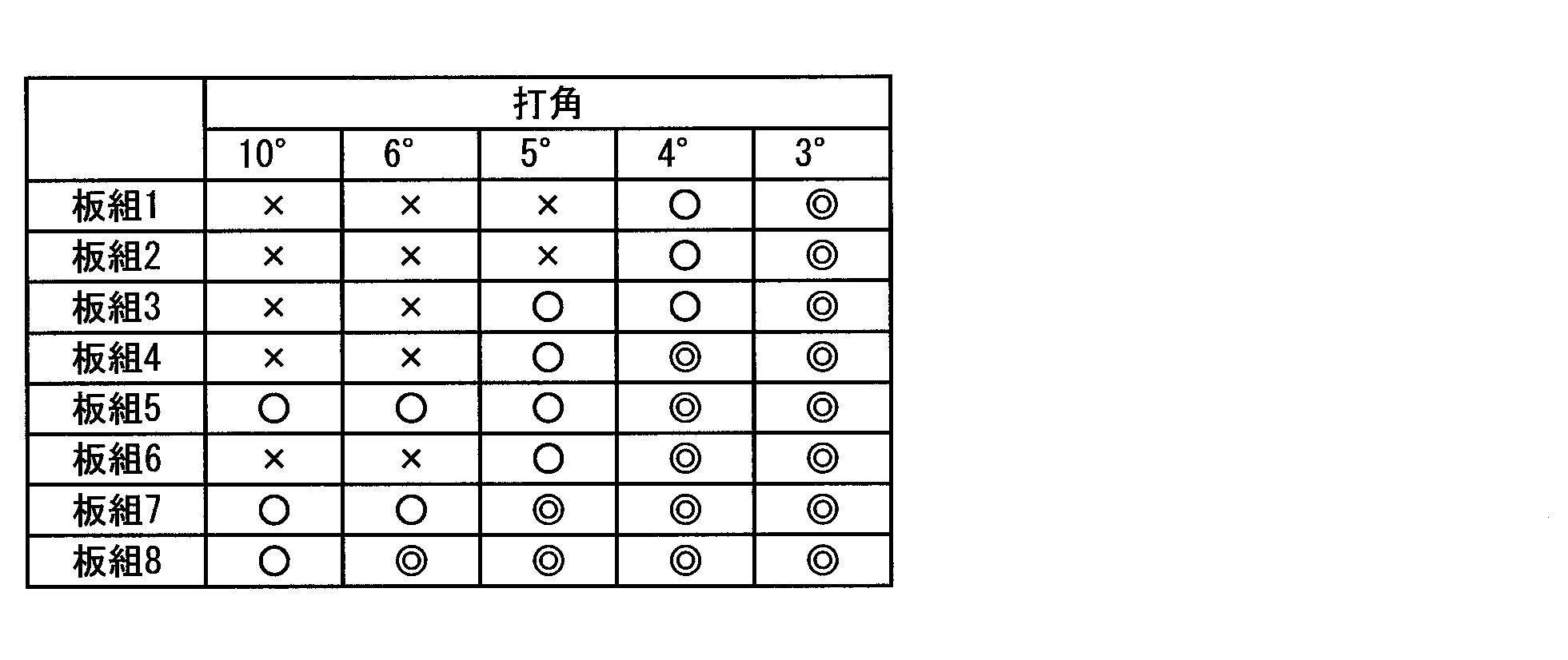
表3に示すように、打角が小さいほど割れが発生しにくく、打角が5度未満の場合には、スポット溶接後、すべての板組で100μm以上の割れは生じず、打角が3度の場合にはすべての板組で割れが生じなかった。
[実施例2]
表4に、使用した金属板について示す。この金属板は、合金化溶融亜鉛めっき鋼板であり、高強度鋼板の両面に亜鉛めっきが被覆されている。
表4に、使用した金属板について示す。この金属板は、合金化溶融亜鉛めっき鋼板であり、高強度鋼板の両面に亜鉛めっきが被覆されている。
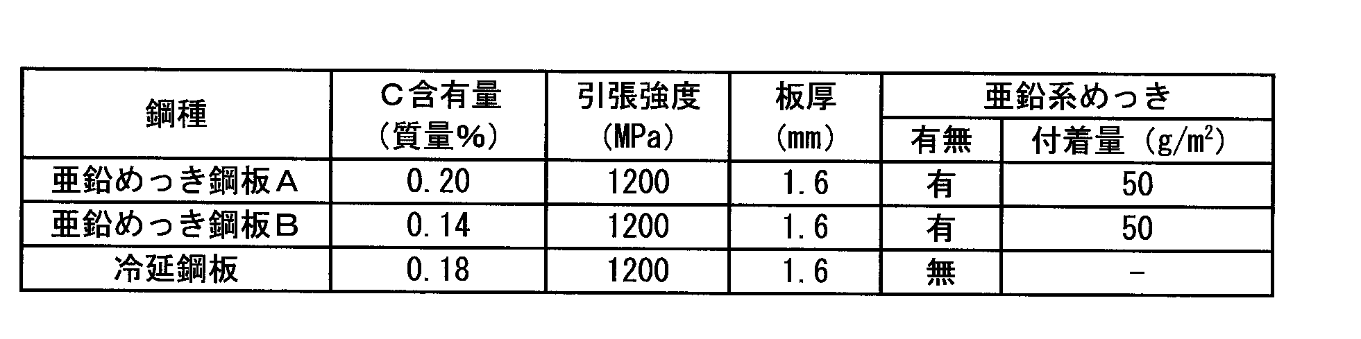
各鋼種の鋼板を2枚ずつ準備し、同じ鋼種の鋼板同士を重ね合わせて、両側から、先端直径6mmのドームラジアス型電極で、2枚の鋼板を挟み込み、加圧力4kNで押し付けつつ、通電時間18サイクル、通電電流9kAとして、スポット溶接を行い、試験片を作成した。電極の打角は5度とした。また、割れの確認は、ナゲットを含むように、試験片を板厚方向に切断して、その断面を確認して行った。さらに、亜鉛めっき鋼板Bと冷延鋼板の板組についても同じ条件でスポット溶接を行い、断面観察により割れの有無を確認した。
亜鉛めっき鋼板Aは、耐食性は良好であるが、コロナボンド直外及びコロナボンドのナゲット際に割れが確認された。亜鉛めっき鋼板Bは、耐食性は良好であり、コロナボンド直外及びコロナボンドのナゲット際の割れは確認されなかった。亜鉛めっき鋼板Bにおいて割れが確認されたのは、C含有量が低いことが関係していると考えられる。一方、冷延鋼板は、耐食性が悪いが、亜鉛めっきがないため、コロナボンド直外及びコロナボンドのナゲット際の割れは確認されなかった。また、亜鉛めっき鋼板Bと冷延鋼板の板組については、冷延鋼板のコロナボンド直外及びコロナボンドのナゲット際の割れが確認された。
次に、コロナボンド直外の割れとコロナボンドのナゲット際の割れが確認された亜鉛めっき鋼板Aを2枚準備し、2枚の鋼板を重ね合わせて、溶接電極の先端に取り付けられる電極チップの接触面の法線と、鋼板表面の法線との角度が5度未満となるように、溶接電極を移動させて、又は、鋼板の溶接箇所を成形して、上記するスポット溶接条件と同じ条件でスポット溶接を行った。その後、得られた試験片について、割れの確認を行った。
その結果、溶接電極を移動させて、打角を2.5度とした場合、コロナボンド直外の割れ及びコロナボンドのナゲット際の割れは発生しなかった。また、鋼板の溶接箇所を成形して、打角を1.5度とした場合、コロナボンド直外の割れ及びコロナボンドのナゲット際の割れは発生しなかった。
[実施例3]
表5に、試験に供した金属板について示す。この金属板は、合金化溶融亜鉛めっき鋼板であり、高強度鋼板の両面に亜鉛めっきが被覆されている。
表5に、試験に供した金属板について示す。この金属板は、合金化溶融亜鉛めっき鋼板であり、高強度鋼板の両面に亜鉛めっきが被覆されている。

表5に示す鋼板を2枚準備し、重ね合わせて、溶接電極で挟み込み、加圧力4kNで押し付けつつ、通電時間18サイクル、通電電流9kAとして、スポット溶接を行い、試験片を作成した。また、電極チップとしては、先端の曲率半径40(mm)、先端径8(mm)の銅製のドームラジアス型のものを用いた。なお、溶接電極の打角を5度とした。
試験片について、割れの確認を行った。割れの確認は、ナゲットを含むように、試験片を板厚方向に切断して、その断面を確認して行った。その結果、コロナボンド直外及びコロナボンドのナゲット際に割れが確認された。
次に、溶接電極の先端に取り付けられる電極チップの接触面の法線と、鋼板表面の法線との角度が5度未満となるように形状を調整した溶接電極を準備した。具体的には、図9に示すホルダー形状を調整した溶接電極、図10(a)に示すシャンク形状を調整した溶接電極、及び、図11に示す電極チップ形状を調整した溶接電極を準備した。
そして、これらの溶接電極を用いたこと以外、上記のスポット溶接条件と同じ条件でスポット溶接を行った。その後、得られた試験片について、割れの確認を行った。その結果、ホルダー形状を調整した溶接電極、シャンク形状を調整した溶接電極、及び、電極チップ形状を調整した溶接電極を用いてスポット溶接したものは、コロナボンド直外の割れ及びコロナボンドのナゲット際の割れが確認されなかった。
本発明によれば、溶接電極の先端に取り付けられる電極チップの接触面の法線と、金属板表面の法線との角度が5度未満でスポット溶接が行われるので、コロナボンド直外及びコロナボンドのナゲット際の残留応力が低くなり、コロナボンド直外及びコロナボンドのナゲット際において液体金属割れの発生を防ぐことができる。よって、本発明は、産業上の利用可能性が高い。
1 金属板
2 ナゲット
3 金属板の表面からナゲットに向かって進展する割れ
4 熱影響部
5 肩部から熱影響部に向かって進展する割れ
6 コロナボンド直外の割れ
7 コロナボンドのナゲット際に割れ
8 金属板の法線
9 溶接電極
9a 溶接電極
9b 溶接電極
9 溶接電極
9c ホルダー
9d シャンク
9e 電極チップ
10 溶接電極の軸
11 鋼板表面の溶接残留応力が高い箇所
12 コロナボンド直外近傍の溶接残留応力の高い箇所
13 溶接電極の先端に取り付けられる電極チップの接触面の法線
Dn ナゲット直径
Dc コロナボンド直径
2 ナゲット
3 金属板の表面からナゲットに向かって進展する割れ
4 熱影響部
5 肩部から熱影響部に向かって進展する割れ
6 コロナボンド直外の割れ
7 コロナボンドのナゲット際に割れ
8 金属板の法線
9 溶接電極
9a 溶接電極
9b 溶接電極
9 溶接電極
9c ホルダー
9d シャンク
9e 電極チップ
10 溶接電極の軸
11 鋼板表面の溶接残留応力が高い箇所
12 コロナボンド直外近傍の溶接残留応力の高い箇所
13 溶接電極の先端に取り付けられる電極チップの接触面の法線
Dn ナゲット直径
Dc コロナボンド直径
Claims (5)
- 複数の金属板が重ね合わせられた箇所を有する部材の上記重ね合わせられた箇所をスポット溶接する方法であって、上記複数の金属板のうち少なくとも1枚の金属板の重ね合わせ面にめっきが施されており、
上記方法は、溶接を実施する前に、溶接電極の先端に取り付けられる電極チップの接触面の法線と、金属板表面の法線との角度を5°未満に調節する工程を含む
ことを特徴とするスポット溶接方法。 - 前記溶接電極の先端に取り付けられる電極チップの接触面の法線と、前記金属板表面の法線との角度を5°未満に調節する方法は、前記部材の成形を含むことを特徴とする請求項1に記載のスポット溶接方法。
- 前記溶接電極の先端に取り付けられる電極チップの接触面の法線と、前記金属板表面の法線との角度を5°未満に調節する方法は、溶接電極の形状の調整を含むことを特徴とする請求項1又は2に記載のスポット溶接方法。
- 前記溶接電極は、ホルダーと、上記ホルダーに組みつけられたシャンクと、上記シャンクに取り付けられた電極チップを備え、
前記溶接電極の形状の調整は、上記ホルダー、上記シャンク、及び上記電極チップの1又は2以上の形状を変更することにより行う
ことを特徴とする請求項3に記載のスポット溶接方法。 - 前記複数の金属板のうち少なくとも1枚の金属板が亜鉛めっき鋼板であることを特徴とする請求項1~4のいずれか1項に記載のスポット溶接方法。
Priority Applications (1)
| Application Number | Priority Date | Filing Date | Title |
|---|---|---|---|
| JP2017517966A JP6384603B2 (ja) | 2015-05-11 | 2016-05-11 | スポット溶接方法 |
Applications Claiming Priority (4)
| Application Number | Priority Date | Filing Date | Title |
|---|---|---|---|
| JP2015096844 | 2015-05-11 | ||
| JP2015-096844 | 2015-05-11 | ||
| JP2015-148709 | 2015-07-28 | ||
| JP2015148709 | 2015-07-28 |
Publications (1)
| Publication Number | Publication Date |
|---|---|
| WO2016181996A1 true WO2016181996A1 (ja) | 2016-11-17 |
Family
ID=57249135
Family Applications (1)
| Application Number | Title | Priority Date | Filing Date |
|---|---|---|---|
| PCT/JP2016/064019 Ceased WO2016181996A1 (ja) | 2015-05-11 | 2016-05-11 | スポット溶接方法 |
Country Status (3)
| Country | Link |
|---|---|
| JP (1) | JP6384603B2 (ja) |
| TW (1) | TWI642506B (ja) |
| WO (1) | WO2016181996A1 (ja) |
Cited By (4)
| Publication number | Priority date | Publication date | Assignee | Title |
|---|---|---|---|---|
| CN107052554A (zh) * | 2017-06-06 | 2017-08-18 | 武汉东环车身系统有限公司 | 一种电阻焊电极角度转换机构 |
| JP6372639B1 (ja) * | 2017-03-01 | 2018-08-15 | Jfeスチール株式会社 | 抵抗スポット溶接方法 |
| NL2022864B1 (en) * | 2019-04-04 | 2020-10-08 | Awl Techniek B V | Method for resistance welding and resistance welding apparatus |
| CN114985887A (zh) * | 2022-06-22 | 2022-09-02 | 天津博世丰通科技有限公司 | 一种防翘曲多层板点焊焊接方法 |
Families Citing this family (2)
| Publication number | Priority date | Publication date | Assignee | Title |
|---|---|---|---|---|
| CN109048021A (zh) * | 2018-09-14 | 2018-12-21 | 上海工程技术大学 | 一种适用于多层薄板的带极点焊焊接工艺 |
| JP7132300B2 (ja) * | 2020-09-18 | 2022-09-06 | フタバ産業株式会社 | 抵抗スポット溶接方法及び抵抗スポット溶接装置 |
Citations (6)
| Publication number | Priority date | Publication date | Assignee | Title |
|---|---|---|---|---|
| JPH02220784A (ja) * | 1989-02-23 | 1990-09-03 | Nippon Steel Corp | 抵抗溶接方法およびその装置 |
| JPH0246308B2 (ja) * | 1981-08-31 | 1990-10-15 | Toyota Motor Co Ltd | |
| JPH05220579A (ja) * | 1991-02-28 | 1993-08-31 | Mitsubishi Motors Corp | パネルの接合方法 |
| JP2001239374A (ja) * | 2000-02-25 | 2001-09-04 | Koyo Giken:Kk | 抵抗溶接機 |
| WO2007065238A1 (en) * | 2005-12-06 | 2007-06-14 | Magna International Inc. | Spot welding tip for a spot welding machine |
| JP2009226425A (ja) * | 2008-03-21 | 2009-10-08 | Mazda Motor Corp | 異種板材のスポット溶接方法 |
Family Cites Families (3)
| Publication number | Priority date | Publication date | Assignee | Title |
|---|---|---|---|---|
| JP3123346B2 (ja) * | 1994-05-31 | 2001-01-09 | 日産自動車株式会社 | 抵抗溶接用補助電極および抵抗溶接方法 |
| JP2004330253A (ja) * | 2003-05-08 | 2004-11-25 | Daihatsu Motor Co Ltd | スポット溶接方法およびスポット溶接装置 |
| JP5870570B2 (ja) * | 2011-09-14 | 2016-03-01 | Jfeスチール株式会社 | 亜鉛系めっき鋼板用の表面処理液ならびに亜鉛系めっき鋼板およびその製造方法 |
-
2016
- 2016-05-11 TW TW105114578A patent/TWI642506B/zh not_active IP Right Cessation
- 2016-05-11 JP JP2017517966A patent/JP6384603B2/ja active Active
- 2016-05-11 WO PCT/JP2016/064019 patent/WO2016181996A1/ja not_active Ceased
Patent Citations (6)
| Publication number | Priority date | Publication date | Assignee | Title |
|---|---|---|---|---|
| JPH0246308B2 (ja) * | 1981-08-31 | 1990-10-15 | Toyota Motor Co Ltd | |
| JPH02220784A (ja) * | 1989-02-23 | 1990-09-03 | Nippon Steel Corp | 抵抗溶接方法およびその装置 |
| JPH05220579A (ja) * | 1991-02-28 | 1993-08-31 | Mitsubishi Motors Corp | パネルの接合方法 |
| JP2001239374A (ja) * | 2000-02-25 | 2001-09-04 | Koyo Giken:Kk | 抵抗溶接機 |
| WO2007065238A1 (en) * | 2005-12-06 | 2007-06-14 | Magna International Inc. | Spot welding tip for a spot welding machine |
| JP2009226425A (ja) * | 2008-03-21 | 2009-10-08 | Mazda Motor Corp | 異種板材のスポット溶接方法 |
Cited By (8)
| Publication number | Priority date | Publication date | Assignee | Title |
|---|---|---|---|---|
| JP6372639B1 (ja) * | 2017-03-01 | 2018-08-15 | Jfeスチール株式会社 | 抵抗スポット溶接方法 |
| WO2018159764A1 (ja) * | 2017-03-01 | 2018-09-07 | Jfeスチール株式会社 | 抵抗スポット溶接方法 |
| EP3590645A4 (en) * | 2017-03-01 | 2020-03-25 | JFE Steel Corporation | RESISTANCE SPOT WELDING PROCESS |
| US11298773B2 (en) | 2017-03-01 | 2022-04-12 | Jfe Steel Corporation | Resistance spot welding method |
| CN107052554A (zh) * | 2017-06-06 | 2017-08-18 | 武汉东环车身系统有限公司 | 一种电阻焊电极角度转换机构 |
| NL2022864B1 (en) * | 2019-04-04 | 2020-10-08 | Awl Techniek B V | Method for resistance welding and resistance welding apparatus |
| CN114985887A (zh) * | 2022-06-22 | 2022-09-02 | 天津博世丰通科技有限公司 | 一种防翘曲多层板点焊焊接方法 |
| CN114985887B (zh) * | 2022-06-22 | 2023-07-28 | 天津翔铄车身科技有限公司 | 一种防翘曲多层板点焊焊接方法 |
Also Published As
| Publication number | Publication date |
|---|---|
| JPWO2016181996A1 (ja) | 2017-11-09 |
| JP6384603B2 (ja) | 2018-09-05 |
| TW201706065A (zh) | 2017-02-16 |
| TWI642506B (zh) | 2018-12-01 |
Similar Documents
| Publication | Publication Date | Title |
|---|---|---|
| JP6108018B2 (ja) | スポット溶接方法 | |
| JP6108017B2 (ja) | スポット溶接方法 | |
| JP6108049B2 (ja) | めっき鋼板のスポット溶接方法 | |
| JP6780386B2 (ja) | スポット溶接方法 | |
| JP6384603B2 (ja) | スポット溶接方法 | |
| TWI622445B (zh) | 點熔接方法 | |
| KR102514674B1 (ko) | 스폿 용접 부재 | |
| JP6278154B2 (ja) | 抵抗スポット溶接方法および溶接部材の製造方法 | |
| JP7364113B2 (ja) | 抵抗スポット溶接部材およびその抵抗スポット溶接方法 | |
| KR102197434B1 (ko) | 저항 스폿 용접 방법 | |
| JP6168246B1 (ja) | 抵抗スポット溶接方法および溶接部材の製造方法 | |
| JP2003103377A (ja) | 高強度めっき鋼板のスポット溶接方法 | |
| JP5168204B2 (ja) | 鋼板のスポット溶接方法 | |
| KR20250048091A (ko) | 용접 부재 및 그 제조 방법 | |
| JP7831700B2 (ja) | 抵抗スポット溶接部材およびその抵抗スポット溶接方法 | |
| JP7831701B2 (ja) | 抵抗スポット溶接部材およびその抵抗スポット溶接方法 | |
| JP7648019B2 (ja) | 抵抗スポット溶接方法、並びに溶接部材の製造方法 | |
| KR20250043562A (ko) | 용접 부재 및 그 제조 방법 | |
| WO2024063010A1 (ja) | 溶接部材およびその製造方法 | |
| KR20250043563A (ko) | 용접 부재 및 그 제조 방법 | |
| KR20250002801A (ko) | 저항 스폿 용접 방법 |
Legal Events
| Date | Code | Title | Description |
|---|---|---|---|
| 121 | Ep: the epo has been informed by wipo that ep was designated in this application |
Ref document number: 16792721 Country of ref document: EP Kind code of ref document: A1 |
|
| ENP | Entry into the national phase |
Ref document number: 2017517966 Country of ref document: JP Kind code of ref document: A |
|
| NENP | Non-entry into the national phase |
Ref country code: DE |
|
| 122 | Ep: pct application non-entry in european phase |
Ref document number: 16792721 Country of ref document: EP Kind code of ref document: A1 |