WO2016181849A1 - 寝具掃除機 - Google Patents
寝具掃除機 Download PDFInfo
- Publication number
- WO2016181849A1 WO2016181849A1 PCT/JP2016/063268 JP2016063268W WO2016181849A1 WO 2016181849 A1 WO2016181849 A1 WO 2016181849A1 JP 2016063268 W JP2016063268 W JP 2016063268W WO 2016181849 A1 WO2016181849 A1 WO 2016181849A1
- Authority
- WO
- WIPO (PCT)
- Prior art keywords
- main body
- body case
- bedding
- air
- suction port
- Prior art date
- Legal status (The legal status is an assumption and is not a legal conclusion. Google has not performed a legal analysis and makes no representation as to the accuracy of the status listed.)
- Ceased
Links
Images





Classifications
-
- D—TEXTILES; PAPER
- D06—TREATMENT OF TEXTILES OR THE LIKE; LAUNDERING; FLEXIBLE MATERIALS NOT OTHERWISE PROVIDED FOR
- D06F—LAUNDERING, DRYING, IRONING, PRESSING OR FOLDING TEXTILE ARTICLES
- D06F58/00—Domestic laundry dryers
-
- D—TEXTILES; PAPER
- D06—TREATMENT OF TEXTILES OR THE LIKE; LAUNDERING; FLEXIBLE MATERIALS NOT OTHERWISE PROVIDED FOR
- D06F—LAUNDERING, DRYING, IRONING, PRESSING OR FOLDING TEXTILE ARTICLES
- D06F58/00—Domestic laundry dryers
- D06F58/30—Drying processes
-
- A—HUMAN NECESSITIES
- A47—FURNITURE; DOMESTIC ARTICLES OR APPLIANCES; COFFEE MILLS; SPICE MILLS; SUCTION CLEANERS IN GENERAL
- A47L—DOMESTIC WASHING OR CLEANING; SUCTION CLEANERS IN GENERAL
- A47L9/00—Details or accessories of suction cleaners, e.g. mechanical means for controlling the suction or for effecting pulsating action; Storing devices specially adapted to suction cleaners or parts thereof; Carrying-vehicles specially adapted for suction cleaners
- A47L9/28—Installation of the electric equipment, e.g. adaptation or attachment to the suction cleaner; Controlling suction cleaners by electric means
Definitions
- the present invention relates to a vacuum cleaner for bedding such as a futon.
- Patent Document 1 proposes a vacuum cleaner intended to collect dust from mattresses and comforters.
- the vacuum cleaner described in Patent Document 1 has a main body in which an electric blower and a filter for collecting dust are incorporated.
- the main body of the vacuum cleaner described in Patent Document 1 is installed between two futons. This main body is moved by the power of the motor along a rail fixed to the outside of the two futons.
- the vacuum cleaner described in Patent Document 1 removes dust along with this movement.
- An object of the present invention is to obtain a bedding cleaner capable of automatically cleaning bedding such as a futon and improving user convenience.
- a bedding cleaner includes a mechanical drive unit that generates a self-propulsive force upon contact with the bedding to be cleaned, a ventilation path having a suction port and a blower outlet, and a suction path through the ventilation path.
- An electric blower that sucks air containing dust, a dust collecting unit that filters dust from an air flow introduced into the ventilation path, and a heating unit that is provided in the ventilation path and heats the air blown from the outlet . The electric blower blows out the air sucked into the ventilation path and heated by the heating means for drying the bedding.
- a bedding cleaner includes a mechanical drive unit that generates a self-propulsive force upon contact with the bedding to be cleaned, a ventilation path having a suction port and a blower outlet, and a suction path through the ventilation path.
- An electric blower that sucks in air containing dust, a dust collecting part that filters dust from the air flow introduced into the ventilation path, a bypass air path that branches off from the electric blower to the outlet, and this bypass air Heating means for heating air from the electric blower that passes through the ventilation path without flowing through the path.
- the bypass air passage and the heating means are provided in the air passage. The electric blower blows air sucked into the ventilation path and heated by the heating means for drying the bedding, and also blows out air from the bypass air path.
- a bedding cleaner includes a mechanical drive unit that generates a self-propelling force and a mechanical drive unit in a closed space formed by overlapping the second bedding on the first bedding.
- a main body case that moves in a predetermined direction, a dust collector that collects dust from the air that passes through the ventilation path formed inside the main body case, an electric blower that circulates air in the ventilation path, and
- the heating means which heats the air in a ventilation path, and the control apparatus which controls electricity supply of an electric blower and the said heating means are provided.
- the ventilation path is formed from the inside of the closed space formed between the first bedding and the second bedding to the air outlet from which the air is introduced to the air outlet.
- the electric blower blows out the air heated by the heating means from the air outlet.
- the mechanical drive unit has a drive wheel that rotates while contacting the upper surface of the first bedding, and the main body case has a first gap between the lower surface of the main body case and the upper surface of the first bedding. It moves with the formed.
- the bedding cleaner of the first aspect of the invention it is not necessary to perform a construction such as installing a mechanical structure such as a moving rail on the furniture, and the bedding can be moved by itself on an object such as a mattress. Can be cleaned.
- the electric blower for cleaning the bedding and the electric blower for drying are shared, the configuration of the entire vacuum cleaner can be reduced in size and the usability can be improved.
- the bypass air passage can be used exclusively for exhaust air other than the hot air supply passage, in addition to the effect of the first invention, the air flow for the hot air is in an appropriate range. Maintains and prevents adverse effects on hot air blowing. For this reason, it is possible to blow out a clean drying air having a necessary temperature and air volume, and a drying effect of the bedding can be obtained.
- the main body case is placed between the first bedding when moving in the closed space formed between the first bedding and the second bedding. It moves horizontally while maintaining the first gap. For this reason, it is avoided that the lower surface of the main body case moves while being in sliding contact with the upper surface of the first bedding, the propulsive force of the main body case is maintained with less power, and the main body case can be smoothly advanced.
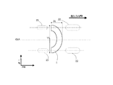
- FIG. 1 It is explanatory drawing which shows the planar positional relationship of the drive wheel, driven wheel, and suction inlet in the bedding cleaner of FIG. It is a center part longitudinal cross-sectional view which shows the modification of the bedding cleaner which concerns on Embodiment 3.
- FIG. It is a center part longitudinal cross-sectional view of the bedding cleaner which concerns on Embodiment 4 of this invention.
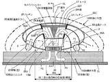
- FIG. 1 is a longitudinal sectional view of a central portion of a bedding cleaner according to Embodiment 1 of the present invention.
- 2 is a cross-sectional view of the central portion of the bedding cleaner of FIG.
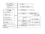
- FIG. 3 is a block diagram showing a configuration relating to the control of the bedding cleaner of FIG.
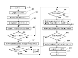
- FIG. 4 is a flowchart showing a control operation of the bedding cleaner of FIG.
- the “bedding” is a bedding having air permeability, and refers to a mattress or a comforter.
- the bed or mattress pad can be a kind of bedding.
- the cloth or bag is also considered as a part of bedding.
- “bedding drying” means supplying warm air to the bedding to remove moisture in the bedding.
- the drying of the bedding includes removing dust from the hot air that has passed through the bedding and supplying clean air when the hot air is supplied. Dust removed by drying the bedding includes, but is not limited to, dirt, pollen, fiber scraps, scattered hair, harmful substances such as dead mites and feces, and pests.
- “cleaning of bedding” or “cleaning of bedding” means that air is sucked from the bedding side to collect dust on the surface or inside of the bedding to clean the bedding.
- a means for collecting dust for example, either one or both of a filter (filter member) and a cyclone type dust collector are used.
- the means for collecting dust is not limited to these two methods.
- the bedding dryer used for the “bedding drying” can be a bedding cleaner.
- “resident” means a person who lives in one house or room with a bedding cleaner.
- residents include related parents, children, siblings, and sisters.
- the resident also includes a visitor who temporarily stays in the living space HA described later for a predetermined period, and other persons who live together.
- residents also include those who borrow one or more living spaces by one or more people.
- the resident may be referred to as a “user”.
- the storage unit 3R includes, for example, a nonvolatile storage device such as a ROM, a flash memory, or an HDD, and a volatile storage device such as a RAM that constitutes a work area.
- FIG. 1 is the bedding cleaner used as the object of this invention.
- FIG. 1 is a longitudinal sectional view of the bedding cleaner 1 viewed from the side in the traveling direction.
- 100A is a mattress (first bedding) to be cleaned by the bedding cleaner 1, and is placed on furniture such as a bed or on the floor.
- 100B is a comforter (second bedding) placed on top of this mattress 100A.
- reference numeral “100” is used.
- These beddings 100 are formed with dimensions sufficiently larger than the height of the user.
- the bedding 100 is roughly divided into those used on a bed and those used directly on a tatami mat or a floor, and the sizes of the two are slightly different. For example, a certain manufacturer's one is for a bed and is called the smallest “single size”.
- the comforter 100B has a width of 150 cm ⁇ a length of 210 cm, and the mattress 100A has a width of about 100 cm ⁇ a length of about 200 cm. Is the size of In what is called a large “double size”, the comforter 100B is 190 cm wide ⁇ 210 cm long, and the mattress 100A is approximately 140 cm wide ⁇ 200 cm long.
- the futon is filled with cotton (also referred to as “filling”), feathers, etc. in a breathable cloth outer bag, so that it retains heat and absorbs and releases moisture (absorbs moisture, Designed to be rich in spitting).
- the cotton here may be synthetic fiber in addition to cotton, and the material is not limited.
- the bedding cleaner 1 is used by being placed on a mattress 100A as shown in FIG. At that time, if the comforter 100B is placed over the bedding cleaner 1, the upper and lower two beddings 100 can be dried simultaneously.
- Reference numeral 2 denotes a main body case that forms the outline of the main body 1 ⁇ / b> A of the bedding cleaner 1.
- the main body case 2 is formed into a perfect circle in a planar shape by integral molding of plastic, and the vertical cross-sectional shape is a horizontally long ellipse with a part of the upper surface being flat as shown in FIG.
- the main body case 2 has a semicircular shape in the entire four directions around the horizontal line HL passing through the upper and lower central portions.
- the body case 2 has a semicircular shape in the four directions around the top surface that appears in the plan view.
- the main body case 2 is normally moved in the traveling direction FD by a mechanical drive unit (also referred to as “mechanical propulsion unit”) 4 described later.
- the main body case 2 has one hemispherical surface from the top to the bottom in the moving direction. That is, it is desirable that the surface of the top portion of the main body case 2 is a three-dimensional curved surface. The reason for this will be described later.
- 2B is the lower surface (bottom surface) of the main body case 2.
- the lower surface 2B is always close to the upper surface of the mattress 100A during the period in which the main body case 2 moves during the bedding drying operation. During the period in which the main body case 2 moves during the bedding drying operation, it is not desirable for the main body case 2 to move while the lower surface 2B is in contact with the upper surface of the mattress 100A and generates a frictional force.
- the bedding vacuum cleaner 1 is devised so that when it moves between the mattress 100A and the comforter 100B by itself, there is little friction with the bedding 100 and the progress is smooth.
- the entire surface of the main body case 2 (at least the upper surface and the four sides on the front, rear, left and right) is formed as smooth as possible on the assumption that it may be in direct contact with the lower surface of the comforter 100B. . That is, the entire surface of the main body case 2 (at least the upper surface and the four sides on the front, rear, left, and right) is formed into a three-dimensional curved surface as described above, and the curved surface is fine enough to catch the surface of the mattress 100A and the comforter 100B. It is formed so that there is no protrusion.
- the smooth surface referred to here may be a surface formed by ordinary plastic molding, and does not require special processing such as special mirror finish.
- suction ports 5A and 5B are suction ports formed respectively on the ceiling surface on the traveling direction side (leading side) of the main body case 2 and the bottom surface on the opposite side.
- the suction ports 5A and 5B are concentrically centered on the center point (CPO) of the main body case 2 as shown in FIG.
- CPO center point
- the suction passage 6 is a cavity communicating vertically from the suction port 5 toward the horizontal line HL.
- a dust collection chamber 8 is connected to a rear side (opposite to the traveling direction FD) from the upper and lower intermediate point of the suction passage 6 through a large circular window 7.
- a filter 9 for dust filtration is installed in the dust collection chamber 8 so as to partition the whole from the ceiling to the bottom.
- the filter 9 has a zigzag vertical cross-sectional shape, and has an increased surface area for filtration.
- the filter 9 is not a single layer, but a fine mesh-like prefilter is placed on the side close to the window 7, that is, on the upstream side of the air flow, and on the downstream side, finer dust is collected than the prefilter.
- a configuration in which a plurality of stages are installed, such as a main filter that can be used, may be used.
- a blower chamber 11 is connected to the rear side of the dust collection chamber 8 through a circular window 10.
- An electric blower 13 having a rotating shaft 12 that is horizontal is installed in the blower chamber 11.
- 13M is a motor of the electric blower 13.
- Reference numeral 14 denotes a fan fixed to the tip of the rotary shaft 12 so as to face the window 10.
- a heating chamber 16 is connected to the rear side from the blower chamber 11 through a circular window 15.
- Reference numeral 17 denotes an electric heater disposed in the heating chamber 16, for example, a PTC heater is used.
- the heater 17 has a fine through-hole formed in a honeycomb shape so that air can pass therethrough.
- the heater 17 is not limited to a PTC heater, and may be a radiation electric heater of another form such as a sheathed heater.
- a blower outlet 20 ⁇ / b> A on the ceiling surface of the rear part of the main body case 2 and a blower outlet 20 ⁇ / b> B on the bottom surface 2 ⁇ / b> B of the rear part of the main body case 2 are provided.
- These two air outlets 20A and 20B are in a position where they overlap in the vertical direction, and as shown in FIG. 2, they are on a concentric circle centered on the center point (CPO) of the main body case 2, and are in an arc shape. Is formed.
- the reference numeral “20” is used.
- the driving wheel 22 is a drive wheel which is a core structure of the mechanical drive unit 4.
- the driving wheel 22 has a large diameter and a relatively wide flat tire shape so as to support the weight of the bedding cleaner 1 and to obtain a sufficient frictional force in contact with the upper surface of the mattress 100A.
- a pair of drive wheels 22 are provided at symmetrical positions on both sides of a center line CLY (right and left) when the main body case 2 is viewed in the Y-axis direction.
- the right driving wheel 22R and the left driving wheel 22L are rotationally driven in the forward and reverse rotation directions by dedicated motors 22MR and 22ML, respectively.
- the traveling wheel 23 is a running wheel which is the core structure of the mechanical drive unit 4. Unlike the driving wheel 22, the traveling wheel 23 is not driven by a driving source such as a motor 22MR, 22ML or the like. The traveling wheel 23 is also referred to as a “driven wheel” because it only rotates as the body case 2 moves while supporting the weight of the body case 2.
- the total weight of the main body case 2 is supported by the driving wheels 22 and the traveling wheels 23.
- the main body case 2 is laid and placed on the upper surface of the comforter 100A and the comforter 100B is hung as shown in FIG.
- the weight of the comforter 100B is further added on the main body case 2.
- the installation area of the driving wheel 22 and the traveling wheel 23, that is, the area where the driving wheel 22 and the traveling wheel 23 are in contact with the mattress 100A is small, the driving wheel 22 and the traveling wheel 23 are separated by the weight of the body case 2 and the comforter 100B. However, it sinks greatly from the upper surface of the mattress 100A.
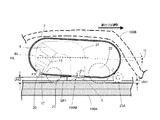
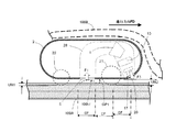
- the bottom surface (lower surface) 2B of the main body case 2 is shaped to push down the mattress 100A. If the main body case 2 is moved in such a state, the lower surface 2B of the main body case 2 may come into contact with the upper surface of the mattress 100A over a wide range, and there is a concern that a frictional resistance that prevents horizontal movement of the main body case 2 may occur. Therefore, in the first embodiment, the weight of the main body case 2 and the comforter 100B, the softness (or hardness) of the mattress 100A, and the like are comprehensively taken into consideration, and a normal comforter 100B is hung as shown in FIG. However, the gap GP is set so that even a slight gap is secured between the bottom surface (lower surface) 2B of the main body case 2 and the upper surface of the mattress 100A. The size of the gap GP may be about 10 mm.
- the position sensor 24 is a position sensor installed so that the detection surface is exposed on the lower surface of the front portion of the main body case 2.
- the position sensor 24 includes a light emitting unit that emits light such as infrared rays on the surface of the mattress 100A on the traveling direction FD side of the bedding cleaner 1, and a light receiving unit (for example, a phototransistor) that receives reflected light from the light emitting unit. Have.
- the detection signal of the position sensor 24 is input to the control device 3. Note that the number of light beams for detection is not limited to one, but may be a plurality. Further, an ultrasonic sensor may be used instead of the infrared sensor.
- dust sensor 25 is a dust sensor that counts the number of dust particles having a predetermined particle diameter or more by applying a laser beam or the like to the air flow sucked into the suction passage 6 from the suction port 5A.
- Various types of such dust sensors are already known. For example, in a self-propelled cleaner introduced in Japanese Patent Application Laid-Open No. 2014-236838, a technique for discriminating the amount of dust contained in an airflow is introduced. Therefore, although detailed description of the dust sensor is omitted, “dust scattering degree information” is generated by the dust determination unit 32 in the control device 3 according to the amount of dust measured by the dust sensor 25.
- the dust sensor 25 is installed between the suction port 5A on the traveling direction FD side and near the window 7, The dust amount of the air immediately after flowing in from the suction port 5A is measured.
- This dust scattering degree information is used by the control device 3 that functions as a host computer of the bedding cleaner 1 to control the rotational speed of the electric blower 13, that is, the air suction capability.
- the inlet 27A is an inlet of the bypass air passage 27 provided immediately before reaching the heating chamber 16 from the blower chamber 11.
- the inlet 27 ⁇ / b> A can maintain the suction air volume of the electric blower 13 by allowing a part of the exhaust flow from the electric blower 13 to escape from the bypass air passage 27 to the outside of the main body case 2.
- the bypass air passage 27 can be used exclusively for exhaust air other than the hot air supply passage, so that the air flow for the hot air is maintained in an appropriate range and adversely affects the hot air blowing. Is prevented. For this reason, it is possible to blow dry air having a necessary temperature and air volume.
- 27 ⁇ / b> B is an outlet of the bypass air passage 27 formed on the bottom surface of the main body case 2 and is elongated in the Y-axis direction.
- a “ventilation passage” 28 that is continuous with 20 is partitioned.
- a bypass air passage 27 that branches from a portion immediately before the electric heater 17 in the middle of the air passage 28 and communicates with the outside of the main body case 2 is also provided.
- the battery 26 is a battery such as a lithium ion battery as a power source.
- the battery 26 is an energy source for the mechanical drive unit 4, the electric blower 13, and the electric heater 17, and is also a power source for the control device 3 and the like described in FIG.
- the battery 26 can be repeatedly charged with a commercial power source for home use (for example, voltage 100 V) and used.
- circuit board 30 is a circuit board on which an input operation unit 31 for a user to provide input operation information to the control device 3, a drive circuit 33 of the electric blower 13, a drive circuit 34 of the mechanical drive unit 4, and the like are mounted.
- One circuit board 30 or two or more circuit boards 30 are installed at intervals in the vertical direction.
- the battery 26 and the circuit board 30 are arranged so as to overlap on the (left and right) center line CLY shown in FIG. For this reason, the circuit board 30, the electric blower 13, and the battery 26 are aligned in a straight line in the vertical direction. Since the electric blower 13 and the battery 26 are the heaviest parts in the bedding cleaner 1, they are installed on the center line CLY in this way, and the weight distribution of the bedding cleaner 1 sandwiches the center line CLY. , To avoid imbalance on both sides. This prevents a difference in the frictional force between the drive wheels 22L and 22R and the mattress 100A. When the drive wheels 22L and 22R are rotated in the same direction by the same number of rotations, the main body case 2 moves straight in the traveling direction FD.
- arrows F1, F2, and F3 indicate airflows flowing through the ventilation path 28, and the signs change in order from F1 to F2 and from F2 to F3.
- F2M represents a first flow from the blower chamber 11 to the heating chamber 16
- F2V represents a flow of air wind from the blower chamber 11 to the inlet 27A of the bypass air passage 27.
- reference numeral 40 denotes an LED light emitting unit having a plurality of LEDs (light emitting diodes) for guiding the operation of the input operation unit 31 with light and performing necessary display.
- 41 is a voice guide unit for guiding the operation of the input operation unit 31 by voice and performing necessary notification.
- the central control unit 42 is a central control unit that forms the core of the control device 3 that functions as a host computer of the bedding cleaner 1.
- the central control unit 42 is configured by a microcomputer, and is connected to a storage unit 3R that stores a control program for controlling the overall operation of the bedding cleaner 1, as will be described later.
- the storage unit 3R and the central control unit 42 are formed as a semiconductor integrated circuit on the circuit board 30 in terms of hardware.
- the dust determination unit 32 receives the detection output of the dust sensor 25 and generates “dust scattering degree information”. That is, according to the amount of dust measured by the dust sensor 25, the dust determination unit 32 generates information that can tell the size of dust scattering.
- the surface determination unit 43 is a surface determination unit of the bedding 100.
- the surface determination unit 43 receives light reception information from a light reception unit (not shown) of the position sensor 24 and determines whether or not the upper surface of the mattress 100A is at a predetermined position. If the existence of the mattress 100A is not detected, a predetermined (absence of the mattress 100A) abnormality notification signal is instantly transmitted to the abnormality processing unit 44.
- the drive circuit 45 is a drive circuit that controls the amount of power to the electric heater 17 and starts and stops energization.
- the drive circuit 45 operates in response to a drive command signal from the control device 3.
- a rotational speed signal from a rotational speed counter 47 that counts the rotational speeds of the two drive wheels 22R and 22L, and whether or not the drive wheels 22L and 22R have rotated in the rotational direction and rotational speed according to the command signal. It is a rotation determination part which determines.
- 48L is a drive motor that rotates the drive wheel 22L.
- Reference numeral 48R denotes a motor that rotates the drive wheels 22R.
- An appropriate differential gear mechanism or the like is interposed between the motors 48L and 48R and the drive wheels 22L and 22R. Note that “48” is used as a reference symbol when the two drive motors are collectively referred to.
- the clock circuit 49 is a clock circuit also called a real time clock.
- the clock circuit 49 is supplied with power from a dedicated power source (built-in battery) different from the battery 26. Thereby, the timepiece circuit 49 is driven for a long period of time.
- the clock circuit 49 may be, for example, a radio-controlled timepiece, and informs the current date and accurate time in seconds if always requested by the control device 3. Therefore, the control device 3 can accurately determine the operation timing of the bedding cleaner 1 based on the time information from the clock circuit 49.
- the drive circuit 45 of the electric heater 17, the drive circuit 33 of the electric blower 13, and the drive circuit 34 of the mechanical drive unit 4 are mounted on a circuit board (not shown) different from the circuit board 30. Also good. Since the electronic components such as the central control unit 42 and the storage unit 3R constituting the input operation unit 31 and the control device 3 are driven at a lower voltage (several volts or less) than the drive circuit 45 or the like, the circuit board It is good to concentrate on 30.
- FIG. 4 shows operation steps after the main power switch (not shown) of the bedding cleaner 1 is turned on.
- Steps S1 to S16 are defined by the operation program of the microcomputer constituting the central control unit 42 in the control device 3.
- the position sensor 24 determines whether or not there is a mattress 100A at a predetermined position (S3). If the signal indicating the existence of the mattress 100A does not reach the central control unit 42 in this step S3, the step does not proceed any further, and the LED light emitting unit 40 and the voice guide unit 41 notify the user. Is called. The content of the notification is, for example, such as “Please set the bedding cleaner 1 at the correct position. The mattress 100A is not detected at the current position.” When a signal indicating the presence of the mattress 100A does not reach the central control unit 42, the abnormal time processing unit 44 determines the contents thereof and instructs the LED light emitting unit 40 and the voice guide unit 41 to perform the above processing. To do. In the input operation unit 31, the LED light emitting unit 40 constituting the display unit and the voice guide unit 41 are activated and operate as described above (S4).
- step S3 when the existence of the mattress 100A is confirmed and there is no abnormality, the LED light emitting unit 40 and the voice guide unit 41 are similarly activated to notify the start of operation.
- the input operation unit 31 is activated to complete the preparation for receiving an input operation from the user, and the voice guide unit 41 is activated to prompt the user to perform an input operation (S5). Then, a display for selecting the operation mode is displayed, or instead of or in addition to this, the user is prompted to select the operation mode with the sound generated from the sound guide unit 41.
- the central control unit 42 of the control device 3 determines whether the automatic operation mode is selected or the manual operation mode is selected (S6).
- the automatic operation mode includes, for example, a mode in which bedding cleaning is performed for a predetermined time. For example, the standard course time for bedding cleaning is set to 60 minutes for a double size mattress.
- the automatic operation mode also includes a “bedding drying” mode.
- the manual operation mode includes a mode in which bedding cleaning is performed for a time set by the user.
- step S6 If the automatic operation mode of “bedding cleaning” is selected in step S6, the process proceeds to the next step (S7). When neither the automatic operation mode nor the manual operation mode is selected, Step S6 is “No” and the process returns to Step S5.
- steps S7 to S15 will be described. These steps show the operation when the automatic operation mode for bedding cleaning is selected.
- the central control unit 42 When the automatic operation mode is selected, the central control unit 42 generates a “cleaning start command signal” indicating that the bedding cleaning operation starts in the automatic operation mode, and transmits it to the mechanical drive unit 4.
- the drive circuit 34 upon receiving the cleaning start command signal, the drive circuit 34 starts driving the drive motors 48L and 48R (S7).
- step S7 measurement of elapsed time from the time when the drive circuit 34 starts driving the drive motors 48L and 48R starts. For example, whether or not the left driving wheel 22L and the right driving wheel 22R have made a quarter rotation is measured by the rotation number counter 47.
- the main body case 2 starts to move in a predetermined traveling direction FD.
- the rotation speed counter 47 counts “1” when the left driving wheel 22L and the right driving wheel 22R rotate by a quarter, and counts “2” when the rotation further rotates by a quarter.
- the quarter rotation of the left driving wheel 22L and the right driving wheel 22R corresponds to, for example, 4 cm or 5 cm in a linear distance.
- step S8 the position sensor 24 determines again whether or not there is a mattress 100A at a predetermined position at a position different from that in step S3 (S8). If the signal indicating the presence of the mattress 100A does not reach the central control unit 42 in this step S8, the step does not proceed any more and the process proceeds to the abnormal stop (error stop) process (S16).
- step S16 the LED light emitting unit 40 and the voice guide unit 41 notify the user. The content of the notification is, for example, as in step S3. “Check the position of the mattress 100A and the position of the bedding cleaner 1. Since the mattress 100A has not been detected at the current position, the operation was stopped. ”
- step S9 the rotation determination unit 46 determines whether the left driving wheel 22L and the right driving wheel 22R have made, for example, a quarter rotation.
- the main body case 2 starts to move in a predetermined traveling direction FD.
- step S9 If it is determined in step S9 that it has moved by a predetermined distance, the process proceeds to the next step S10.
- step S10 while the drive of the mechanical drive unit 4 is temporarily stopped, the electric heater 17 is energized, and the electric blower 13 is also energized, and the mattress 100A and the comforter are introduced from the suction port 5 of the main body case 2. Air from inside 100 ⁇ / b> B and between them is sucked into the suction passage 6. The dust in the air flow is collected by the filter 9, and only clean air reaches the heating chamber 16 and is blown out from the outlet 20 as warm air.
- step S10 the main body case 2 blows warm air in the direction of the mattress 100A and the comforter 100B while being temporarily stopped at the position where the mattress 100A is located, so that the futons can be dried.
- the pause period and the hot air blowing time are synchronized, and this drying operation is performed for 10 seconds or 15 seconds, for example. If predetermined time passes, electricity supply to the electric heater 17 and the electric blower 13 will stop. Then, the count of the amount that the main body case 2 has moved in the predetermined traveling direction FD is reset and returns to zero.
- step S11 the central control unit 42 transmits a drive start command signal to the mechanical drive unit 4, and upon receiving the command signal, the drive circuit 34 starts driving the drive motors 48L and 48R again.
- next step S12 it is determined whether or not the elapsed time from the point of step S7 has reached a predetermined time (for example, 60 minutes as described above).
- a predetermined time for example, 60 minutes as described above.
- the LED light emitting unit 40 displays a display indicating the end of the operation, and the voice guide unit 41 similarly performs the automatic operation in a predetermined program.
- the notification that the street has been completed is made by voice (S13). If the predetermined time has not been reached, the process returns to step S8.
- step S14 the main power switch is automatically turned OFF, and a series of bedding cleaning operations is finished (S15).
- the bedding cleaner 1 described in the first embodiment includes a mechanical drive unit 4 that generates a self-propelling force upon contact with the bedding 100 to be cleaned, a suction port 5 through which air is sucked, and a blowout port through which air is blown out.
- a ventilation passage 28 having an electric motor 20, an electric blower 13 that sucks air containing dust from the suction port 5 into the ventilation passage 28, a dust collecting unit that filters dust from an air flow introduced into the ventilation passage 28, and Heating means provided in the ventilation path 28 for heating the air blown out from the air outlet 20.
- the electric blower 13 blows out the dust-collected air sucked into the ventilation path 28 and heated by the heating means for drying the bedding 100.
- the bedding cleaner 1 is realized by the following specific configuration in the first embodiment. That is, the bedding cleaner 1 includes a mechanical drive unit 4 that generates a self-propelling force in contact with the mattress 100A and the comforter 100B to be cleaned.
- the bedding cleaner 1 has an air passage 28 having two upper and lower suction ports 5A and 5B through which air from the mattress 100A and the comforter 100B is sucked and two upper and lower air outlets 20A and 20B from which air is blown out.
- the bedding cleaner 1 includes an electric blower 13 that sucks air containing dust from the suction ports 5A and 5B into the ventilation path 28, and a dust collection chamber 8 that filters dust from the air flow introduced into the ventilation path 28. And a filter 9 disposed in the.
- the ventilation path 28 is provided with an electric heater 17 that heats air blown from the outlets 20A and 20B.
- the electric blower 13 blows out the dust-collected air sucked into the ventilation path 28 and heated by the electric heater 17 for drying both the mattress 100A and the comforter 100B.
- the bedding cleaner 1 According to the bedding cleaner 1 according to the first embodiment, no work such as installation of a mechanical structure such as a moving rail on the furniture is required, and the main body case is rotated on the mattress 100A by rotating the driving wheels 22L and 22R. 2 moves in a predetermined direction, and in the course of the movement, air is sucked in from the mattress 100A and the comforter 100B side, dust in the airflow is removed to make clean air, and the upper and lower parts of the main body case 2 are again two places.
- the air outlets 20A and 20B can be blown out, and the bedding can be cleaned. Further, when such clean air is blown out, the air is heated and blown out, so that the mattress 100A and the comforter 100B can be dried.
- the electric blower 13 for cleaning the bedding is also the electric blower 13 that blows out the warm air for drying, the size of the ventilation path 28 can be reduced, whereby the configuration of the entire bedding cleaner 1 can be reduced. Usability can be improved.
- an electric device that reduces the physical and time burden on the user for the purpose of maintaining a comfortable bedding and realizing a comfortable sleep.
- a cleaning function, a drying function, and an autonomous running function suitable for bedding the labor of the user is reduced and the maintenance time is shortened.
- sharing the electric blower 13 necessary for the cleaning function and the drying function it is possible to realize a reduction in size, weight, and cost.
- the bedding cleaner 1 has a mechanical drive unit 4 that contacts the bedding 100 to be cleaned and generates a self-propelling force, an air inlet 5 through which air is sucked, and an air outlet 20 through which air is blown out. 28, an electric blower 13 that sucks air containing dust from the suction port 5 into the ventilation path, a dust collecting unit that filters dust from the air flow introduced into the ventilation path 28, and an outlet from the electric blower 13 And a heating unit that heats the air from the electric blower 13 that passes through the ventilation path 28 without flowing through the bypass ventilation path 27.
- the electric blower 13 blows air sucked into the ventilation path 28 and heated by the heating means for drying the bedding, and also blows out air from the bypass air path 27.
- the bedding cleaner 1 is realized by the following specific configuration. That is, the bedding cleaner 1 includes a mechanical drive unit 4 that generates a self-propelling force in contact with the mattress 100A and the comforter 100B to be cleaned.
- the bedding cleaner 1 includes an air passage 28 having two upper and lower suction ports 5A and 5B through which air from the mattress 100A and the comforter 100B is sucked and two upper and lower air outlets 20A and 20B from which air is blown out.
- the bedding cleaner 1 includes an electric blower 13 that sucks air containing dust from the suction ports 5A and 5B into the ventilation path 28, and a dust collection chamber 8 that filters dust from the air flow introduced into the ventilation path 28. And a filter 9 disposed in the.
- the bypass air path 27 branched in the middle from the electric blower 13 to the blower outlet 20, and the electricity that heats the air from the electric blower 13 that passes through the ventilation path 28 without flowing through the bypass air path 27.
- a heater 17 The electric blower 13 blows out the dust-collected air sucked into the ventilation passage 28 and heated by the electric heater 17 for drying the bedding, and also blows out the dust-collected air from the bypass air passage 27.
- bypass air passage 27 can be used exclusively for exhaust air other than the hot air supply passage, the air flow for hot air that has been collected and cleaned is maintained in an appropriate range while maintaining the warm air flow. The adverse effect on the wind blowing is prevented. For this reason, it is possible to blow out a clean dry air having a necessary temperature and air volume.
- the bedding cleaner 1 has a main body case 2 in which a ventilation path 28, a dust collection unit, an electric heater 17, and an electric blower 13 are built.
- a suction port 5B and a blower outlet 20B are formed on the lower surface of the main body case 2 with a space in between as shown in FIG. For this reason, it can suppress that the blown-out air returns to the suction inlet 5B by a short path
- the suction port 5 ⁇ / b> B is disposed on the leading side in the direction in which the main body case 2 advances by the mechanical drive unit 4.
- the blower outlet 20 ⁇ / b> B is disposed on the rear side in the direction in which the main body case 2 advances by the mechanical drive unit 4.
- the suction port 5 ⁇ / b> A is formed on the upper surface of the main body case 2.
- the suction port 5 ⁇ / b> B is formed on the lower surface of the main body case 2. That is, the suction port 5 is formed on the upper surface and the lower surface of the main body case 2.
- the air outlet 20 ⁇ / b> A is formed on the upper surface of the main body case 2.
- the air outlet 20 ⁇ / b> B is formed on the lower surface of the main body case 2. That is, the air outlet 20 is formed on the upper surface and the lower surface of the main body case 2.
- the suction inlet 5 and the blower outlet 20 are formed at intervals.
- the blown air can be prevented from returning to the suction port 5 by a short path, and air can be introduced from both the mattress 100A and the comforter 100B, and warm air can be blown to both sides. Both 100A and the comforter 100B can be efficiently cleaned by one operation.
- the suction port 5 ⁇ / b> A and the suction port 5 ⁇ / b> B, that is, the suction port 5 are arranged on the leading side in the direction in which the main body case 2 advances by the mechanical drive unit 4.
- the blower outlet 20 ⁇ / b> A and the blower outlet 20 ⁇ / b> B, that is, the blower outlet 20 are arranged on the rear side in the direction in which the main body case 2 travels by the mechanical drive unit 4. For this reason, since dust can be absorbed at the front side of the main body case 2, the dust absorption effect can be increased over a wide range of the bedding 100.
- the suction port 5 and the air outlet 20 are formed concentrically with respect to one point (center point CPO). For this reason, even when the body case 2 changes direction (turns) by 90 degrees or more, it does not greatly change the positions of the suction port 5 and the air outlet 20 and continuously sucks or dries from the state before the direction change. can do.
- the electric blower 13 is arrange
- the entire body case 2 is circular or horizontally long as shown in FIG.
- the comforter 100 ⁇ / b> B is guided upward by the outer shape of the main body case 2.
- the comforter 100B does not have a great resistance to the forward travel of the main body case 2, and the main body case 2 can travel straight ahead stably.
- a battery 26 serving as a power supply source for the mechanical drive unit 4, the electric heater 17, and the electric blower 13 is built in the main body case 2.
- the battery 26 and the electric blower 13 are arranged such that the electric blower 13 is located directly above the battery 26. Further, the battery 26 and the electric blower 13 are disposed on the center line CLY along the direction in which the main body case 2 travels. For this reason, the heavy battery 26 and the electric blower 13 are positioned on the center line CLY of the main body case 2, and the position of the center of gravity of the main body case 2 is positioned at the center thereof.
- the main body case 2 even when the main body case 2 receives a force that makes contact with the lower surface of the comforter 100B and hinders its progress, the main body case 2 generates a uniform thrust force in the left-right symmetry, thereby It is possible to go straight ahead stably.
- the suction port 5 is formed on the upper surface and the lower surface of the main body case 2, respectively.
- the upper suction port 5 and the lower suction port 5 communicate with each other via a common suction passage 6. Since it is such a structure, even if it becomes the state where the surface cloth of the quilt 100A or the comforter 100B is attracted to one of the suction ports 5, the other suction port 5 is connected to the ventilation path 28 via the suction passage 6. Air is inhaled. For this reason, it is possible to avoid the situation in which the main body case 2 is advanced while the futon 100A and the comforter 100B are strongly attracted to the suction port, and the main body case 2 can be smoothly advanced with less driving energy.
- FIG. 5 is a longitudinal sectional view of the central portion of the bedding cleaner according to Embodiment 2 of the present invention.
- FIG. 6 is a longitudinal sectional view of the central part (AA line) of the bedding cleaner of FIG.
- FIG. 7 is a block diagram showing a configuration relating to the control of the bedding cleaner of FIG.
- FIG. 8 is an explanatory diagram showing the relationship between the moving path (trajectory) of the bedding cleaner shown in FIG. 5 and the mattress.
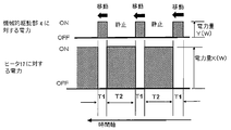
- FIG. 9 is an explanatory diagram of the timing of intermittent movement and power supply of the bedding cleaner shown in FIG.
- FIG. 10 is an explanatory diagram showing a movement path (trajectory) of the bedding cleaner shown in FIG.
- symbol is attached
- FIG. 5 is a longitudinal sectional view of the bedding cleaner 1 viewed from the rear (back) side in the traveling direction FD.
- the bedding cleaner 1 is used by placing it on a mattress 100 ⁇ / b> A, as in the first embodiment. At that time, if the comforter 100B is placed over the bedding cleaner 1, the upper and lower two beddings 100 can be simultaneously cleaned and dried.
- Reference numeral 2 denotes a main body case that forms the main body outline of the bedding cleaner 1.
- the main body case 2 is formed into a perfect circle in a planar shape by integral molding of plastic.
- the main body case 2 has an elliptical cross-sectional shape.
- the bedding cleaner 1 when the bedding cleaner 1 moves between the mattress 100A and the comforter 100B by itself, the bedding cleaner 1 has less friction with the bedding 100 and proceeds smoothly.
- the entire surface of the main body case 2 (at least the upper surface, the front, back, left, and right side surfaces) is formed as smooth as possible on the assumption that it directly contacts the lower surface of the comforter 100B. That is, the entire surface of the main body case 2 (at least the upper surface and the four sides on the front, back, left, and right) is formed in a three-dimensional curved surface, and the curved surface is formed so that there are no fine protrusions on which the surface of the mattress 100A is caught. . These points are basically the same as those in the first embodiment.
- the blower outlet 20 is an air outlet (for clean air and hot air) formed in the center of the bottom surface of the main body case 2.
- the planar shape of the blower outlet 20 is a horizontally long rectangle or a horizontally long ellipse.
- the horizontal width of the air outlet 20 is SW as shown in FIG.
- the blower outlet 20 is formed in the length HW in the advancing direction FD of the bedding cleaner 1. As described above, since the air outlet 20 has a horizontally long shape when seen in a plan view, a relationship of SW> HW is established.
- the drying zone W is a drying area depending on the air outlet 20 of the main body case 2.
- the drying zone W is a width that is determined to allow the mattress 100A to be dried when the bedding cleaner 1 moves in the traveling direction FD.
- the drying zone W is at least twice as large as the width dimension SW of the air outlet 20.
- the drying zone W changes depending on the distance between the air outlet 20 and the mattress 100A, the blowing speed of the hot air, and the like. Therefore, the drying area W always has a constant ratio with respect to the width of the air outlet 20. Don't be.
- the outlet 20 be located as close as possible to the upper surface of the mattress 100A in order to introduce as much hot air as possible into the mattress 100A.
- the lower end edge of the air outlet 20 may come into contact with the upper surface of the mattress 100 ⁇ / b> A when the main body case 2 is moved, which may hinder smooth progress of the main body case 2. Therefore, during the period when the main body case 2 of the bedding cleaner 1 is moving in the traveling direction FD, the lower edge of the air outlet 20 may be separated from the upper surface of the mattress 100A.
- the position of the lower end edge of the air outlet 20 becomes lower (than during the movement of the main body case 2) or comes into contact with the upper surface of the mattress 100A.
- a mechanism for moving the air outlet 20 up and down may be provided.
- the 17 is an electric heater provided so as to lie in the center of the outlet 20, and a PTC heater is used.
- the heater 17 has a number of through holes for ventilation in the vertical direction.
- An electric blower 13 is disposed at a position directly above the heater 17.
- the 13M is a motor of the electric blower 13, and is supported by a circular blow case 50C having an open top surface.
- the electric blower 13 and the electric heater 17 serve as a hot air supply source when bedding such as the mattress 100A is dried with hot air.
- the electric blower 13 also serves as an air flow generating means for introducing the dust.
- the motor 13M and the fan 14 of the electric blower 13 are arranged in the center of the wind tunnel (ventilation duct) 55 described later so that the bedding 100 can be shared in both the cleaning and drying scenes.
- Numeral 22 is four wheels (drive wheels) having the same size, shape and material.
- the wheels (drive wheels) 22 are arranged so as to surround the front, rear, left and right of the air outlet 20.
- two wheels (drive wheels) 22 are arranged on the right side of the air outlet 20 in the front-rear direction along the traveling direction FD, and are symmetrically located on the left side of the air outlet 20. The remaining two are arranged.
- at least one of the left and right wheels among these wheels 22 is rotationally driven by a dedicated motor, respectively, and exerts a propulsive force that moves the main body case 2 forward, backward, and changes direction.
- one each of these wheels 22 is separately driven by a wheel drive unit (drive circuit) 34 to be described later.
- the bedding cleaner 1 moves forward or backward when the left and right wheels 22 of the main body case 2 rotate in the same direction, and changes direction when both wheels rotate in opposite directions.
- the wheel 22 and the drive circuit 34 are main components of the mechanical drive unit 4.
- the four wheels 22 are given sufficient rotational driving force to advance the main body case 2 in a predetermined direction.
- the upper surface of the mattress 100A is formed of a material that generates frictional resistance.
- wheels 22 that are in contact with the upper surface of the mattress 100A are arranged at symmetrical positions across the vertical center line VL. For this reason, even if the main body case 2 is in contact with the lower surface of the comforter 100B and receives a force that prevents the main body case 2 from proceeding, the main body case 2 is caused to generate a uniform propulsive force symmetrically left and right. It is possible to proceed in a straight line state stably.
- Numeral 5 is a suction port formed so as to be scattered at four places on the lower surface of the main body case 2.
- the air inlet 5 serves as an inlet for introducing air into the body case 2.
- the suction port 5 is provided at a position surrounding the front, rear, left and right of the wheel 22 when the main body case 2 is viewed from below.
- size caliber
- the diameter of the suction port 5 in the traveling direction FD of the bedding cleaner 1 may be formed smaller than the diameter of the suction port 5 in the reverse direction.
- the air volume sucked from the rear side may be larger than the air volume on the front side. Conversely, the air volume sucked from the front side may be increased. Moreover, it is not necessary to make all the opening shapes of the suction inlet 5 into the same shape.
- Reference numeral 52 denotes a suction port unit that is inserted and installed in each of the four suction ports 5 from the outside of the main body case 2.
- the suction port unit 52 is formed in a hollow cylindrical shape so as to communicate with the suction port 5.
- a large air hole is formed in the lowermost bottom surface of the suction port unit 52.
- a rotating brush 53 (see FIG. 7) is arranged such that the lower end is in contact with the surface of the mattress 100A.
- the brush 53 is supported on a horizontal rotating shaft.
- the brush 53 is rotated around the rotation shaft by a brush drive unit 54 having a dedicated motor, and scrapes dust on the upper surface of the mattress 100A.
- the suction port unit 52 is structured such that the user can remove it from the suction port 5 and attach it.
- a brush 53 and a coarse filter (referred to as “prefilter”, not shown) that collects dust in the air are provided.
- the pre-filter and the brush 53 can be further removed from the inlet unit 52 and cleaned and washed (washed with water). For this reason, the user can remove lint and other dust accumulated in the prefilter using the bedding cleaner 1.
- the hair entangled with the brush 53 can also be removed.
- the first gear portion formed at one end portion of the brush 53 is the second gear located inside the main body case 2. Engage with the gear. Thereby, the brush 53 receives a rotational driving force.
- the second gear is rotationally driven by a dedicated motor (not shown).
- the ventilation duct 55 is a ventilation duct occupying a large volume in the main body case 2.
- the ventilation duct 55 includes an inlet portion 55 ⁇ / b> A connected to the four suction ports 5.
- An inverted conical dust collecting cylinder portion 55C is formed in the center portion, which has outlet portions 55B connected to the respective inlet portions 55A.
- a circular opening 55U formed on the lower surface of the dust collecting cylinder 55C is an outlet for airflow.
- the opening 55U is in close contact with the upper end of the circular air blowing case 50 whose upper surface is open.
- the internal space of the dust collection cylinder portion 55C forms a dust collection chamber 8.
- the main filter 9 is a main filter installed from the upper surface opening part 55T of the dust collection cylinder part 55C so that it may closely_contact
- the main filter 9 is formed in a cup shape.
- the main filter 9 has a function of filtering finer dust than the pre-filter, and is formed of plastic, nonwoven fabric, or the like. Note that the main filter 9 is provided with circular windows that match the diameters of the outlet portions 55B at the opposing portions of the four outlet portions 55B. As a result, the main filter 9 can introduce air sucked into the ventilation duct 55.
- the lid 51 is a rigid lid installed so as to close the upper surface opening of the main filter 9.
- the lid 51 is made of a plastic material or the like.
- the lid 51 is detachably attached to the upper opening edge of the main filter 9. When the lid 51 is lifted, the main filter 9 is lifted up and can be taken out from the dust collecting cylinder portion 55C.
- a series of ventilation paths extending from the ventilation duct 55 having the inlet portion 55 ⁇ / b> A and the outlet portion 55 ⁇ / b> B to the dust collection cylinder portion 55 ⁇ / b> C, the blower case 50, and the blower outlet 20. 28 is formed.
- the electric blower 13 is arranged in the middle of the ventilation path 28, and the air on the bedding 100 is sucked from the inlet 55A, and the dust contained in the air flow is separated from the air by the main filter 9. ing.
- the airflow generating means for supplying warm air and the air introducing means for exerting the basic function of the vacuum cleaner for collecting dust are realized by the common electric blower 13 and the ventilation path 28. .
- the outer case of the main body case 2 has a window 2W that is covered with a lid 2T so as to be opened and closed.
- the dust collection chamber 8 (the internal space of the dust collection cylinder portion 55C) is configured to be opened to the outside of the main body case 2. For this reason, the dust accumulated on the main filter 9 can be taken out from the window 2W.
- the internal space of the main body case 2 is effectively utilized, and the common electric blower 13 realizes the supply of warm air and the generation of air current for cleaning. Can be configured compactly.
- Numeral 56 is a silencer rectifying plate attached in a shape protruding downward to the center of the lower surface of the lid 51.
- the silencer rectifying plate 56 is formed in an inverted conical shape from a material that easily absorbs sound.
- the silencer rectifying plate 56 is located at a point where the air flows sucked from the four suction ports 5 merge, and is installed to obtain an effect of reducing noise generated when the air flows merge.
- the main filter 9 may be replaceable so that it can be discarded as it is when dust accumulates. In that case, it is economical if the component in which the lid 51 and the silencer rectifying plate 56 are coupled can be used many times.
- the circular window 2W is formed at the center of the upper surface of the main body case 2 so that the main filter 9 can be taken out by lifting the lid 51.
- This window is normally closed with a circular lid 2T.
- 2P is a packing attached to the outer peripheral edge of the lid 2T for increasing confidentiality.
- the packing 2P is made of silicon rubber having a high elasticity and has a hollow structure.
- Reference numeral 57 denotes a control unit main circuit board installed at an upper portion of the wind tunnel 55 at a rear position when viewed from the dust collecting cylinder portion 55C.
- Various electric / electronic components constituting the control device 3 of the bedding cleaner 1 to be described later are mounted on the control unit main circuit board 57.
- the input operation unit 31 includes a capacitance change detection electrode installed inside the ceiling surface of the main body case 2.
- the optical sensor 59 is an optical sensor attached to the end of the input circuit board 58.
- the optical sensor 59 detects visible light (indicated by broken arrows in FIG. 6) such as various illumination lights and sunlight from above the main body case 2. That is, when the optical sensor 59 senses such visible light, it outputs a predetermined detection signal to the control device 3.
- the main body case 2 is formed of, for example, a milky white material (opaque material) so that the optical sensor 59 can sense light from the outside of the main body case 2.
- the portion directly above the optical sensor 59 is formed with a window in which a transparent plate is fitted or has a thin shape so as to easily transmit visible light (however, it has a thin structure). In addition, it has sufficient strength against the load from above and has been devised so as not to impair the rigidity of the entire main body case 2).
- NFC near field communication
- the near field communication (NFC) input / output unit 63 is mounted on the input circuit board 58.
- the dust sensor 60 is a dust sensor that counts the number of dust particles having a predetermined particle diameter or more by applying a laser beam or the like to the air flow sucked into the ventilation duct 55 from the suction port 5.
- the dust sensor 60 corresponds to the dust sensor 25 of the first embodiment.
- the dust sensor 60 is installed near the suction port 5 on the traveling direction FD side, and measures the amount of dust in the air immediately after flowing in from the suction port 5.
- the dust scattering degree information generated according to the amount of dust measured by the dust sensor 60 is obtained by the control device 3 functioning as a host computer of the bedding cleaner 1. Used for control.
- 61 is an ion generating device that generates and mixes negative ions with the air flow sucked into the ventilation duct 55 from the suction port 5 on the rear side of the main body case 2. Note that an ozone generating device may be installed instead of the ion generating device. In any case, 61 is installed for the purpose of exerting sterilizing and deodorizing effects on the air above the bedding 100 flowing into the ventilation duct 55.
- a light emitting unit 64 emits special light to the surface of the mattress 100A on the traveling direction FD side of the bedding cleaner 1 and includes one or a plurality of LED elements.
- a light receiving unit 65 receives reflected light from the light emitting unit 64 and uses, for example, a phototransistor.
- the light emitting unit 64 and the light receiving unit 65 constitute a main part of the bedding surface detection unit 62.
- the “special light” of the light emitting unit 64 is the same light in the visible light region as that of sunlight or the light from the indoor lighting, or light in the infrared light emitting region.
- the 67 is a light emitting unit constituting a dirt detecting unit 68 described later.
- Reference numeral 69 denotes a light receiving unit such as a camera, which is one part constituting the dirt detection unit 68.
- the light receiving unit 69 photographs a predetermined range (for example, a circular or elliptical range having a diameter of several centimeters) on the upper surface of the mattress 100A illuminated by the light emitting unit 67.
- the light receiving unit 69 is desirably a CCD camera or the like that can enlarge and close the surface of the bedding 100 such as a mattress 100A.
- the light emitting unit 67 includes a light emitting diode (LED) that emits special light for photographing the bedding 100.
- the special light is, for example, ultraviolet light having a wavelength of 375 to 400 nm (nanometer).
- SF is the distance that the bedding cleaner 1 travels in the traveling direction FD when the bedding cleaner 1 repeatedly moves, stops, and moves. This distance SF is about 1.5 to 2 times larger than the width HW of the air outlet 20 in the front-rear direction.
- a touch panel type sensing unit using a change in capacitance is arranged on the side closer to the light emitting unit 64 than the NFC input / output unit 63.
- the sensing unit also serves as a touch-type input operation unit 31 (see FIG. 7).
- the main body case 2 displays a target position indicating the information communication terminal device so that the user can visually recognize the information communication terminal device (not shown) having an NFC (near field communication) function.
- a light emitting diode element (not shown) is arranged. The light emitting diode element is illuminated with light from the inside of the main body case 2C.
- the light emitting diode element is disposed on the upper surface of the input circuit board 58 corresponding to the NFC input / output unit 63.
- Reference numeral 70 denotes furniture such as a floor or a bed of a house on which the mattress 100A is placed.
- FIG. 7 is a block diagram showing an internal main configuration of the bedding cleaner 1, and the components described in FIG. 5 and FIG.
- Reference numeral 66 denotes a temporary storage unit that temporarily stores data of reflected light from an object such as the mattress 100A received by the light receiving unit 65.
- Reference numeral 71 denotes a determination unit that constitutes a core part of the bedding surface detection unit 62. The determination unit 71 operates in response to a command signal from the imaging unit 72. The determination part 71 analyzes the data of the reflected light from the surface of the mattress 100A, and determines whether the mattress 100A is within a predetermined range.
- the 73 is a stain determination unit having the core function of the bedding stain detection unit 68.
- the determination unit 73 receives a command from the photographing unit 74 and analyzes image data of one screen photographed with the light of the black light from the light emitting unit 67 using a dedicated algorithm.
- the determination unit 73 determines the degree of difference for each screen from the comparison result with the reference screen. For example, the determination unit 73 counts the presence / absence of a point where the brightness and the surroundings change in one screen while keeping one screen in a light blue background color.
- some bacteria have a fluorescent substance, and the breeding part of these bacteria is identified as a white color from the surroundings by applying black light.
- the bedding contamination determination unit 76 notifies the user of the degree of contamination of the bedding 100 by means of audio information from the audio guide unit 41, light emission via the LED light emission unit 40, blinking, and the like.
- the control device 3 controls the wireless communication unit (wireless input / output unit) described later.
- the fact that the bedding is dirty and detailed judgment data may be collectively transmitted to an information receiving device (not shown) such as an information communication terminal device or a home server provided inside the home via 77.
- the voice guide unit 41 includes a voice synthesizer (not shown) and a speaker (not shown) that emits voice according to the voice guide signal generated by the voice synthesizer.
- Reference numeral 44 denotes an abnormality processing unit that has a program for performing a predetermined process such as an emergency stop when an abnormality occurs, and performs an abnormality determination.
- the abnormal time processing unit 44 is supplied from various electric components, the electric heater 17, the electric blower 13, and the like. Monitor the data to determine if there are any abnormal operating conditions.
- Reference numeral 78 denotes a current detection unit that detects whether the brush 53 is rotating as specified.
- the current detection unit 78 monitors the current flowing through the motor of the brush drive unit 54.
- 79 is a commercial power supply of 100 V-50 Hz or 60 Hz.
- a main power switch (not shown) that can be opened and closed by the user is provided downstream of the commercial power supply 79, and an open / close button of the switch is disposed in the input operation unit 31.
- the electric heater 17 is a PTC heater and has a characteristic of automatically suppressing a current flowing through itself as the temperature rises. Although a temperature detection element dedicated to this PTC heater is not provided, a heat sensitive element, such as a thermistor, for monitoring the internal temperature of the ventilation duct 55 or the main body case 2 is provided so that the temperature does not become abnormally high.
- the abnormality processing unit 44 monitors.
- FIG. 8 is an explanatory view showing the movement path MK of the bedding cleaner 1 and shows a state in which the bedding cleaner 1 has progressed halfway on the double size mattress 100A.
- the configurations described in FIGS. 5 to 7 are denoted by the same reference numerals and redundant description is omitted.
- the movement trajectory (path) MK of the bedding cleaner 1 is from the start point (movement start point) SAP to the end point (movement end point) STP in the example of FIG.
- the movement path MK is not limited to a path such as so-called “one-stroke drawing” as described above, and may be a path that reciprocates back and forth or left and right along a straight line or a curve.
- the starting point SAP and the end point STP may be the same. That is, the movement route MK may be set so that it always returns to the departure point.
- Control data indicating such a movement path MK is incorporated as a program in the microcomputer constituting the central control unit 42 of the control device 3 of the bedding cleaner 1 as coordinate data of the X axis and the Y axis as shown in FIG. It is.
- the total length of the movement route MK and the shape of the route should be determined in correspondence with the size of the flat area of the mattress 100A as much as possible.
- an input key such as “Area: Large” or “Futon Size: Large” is displayed, and when it is selected, The desired dry area is obtained.
- setting information such as the size of the mattress 100A and the desired cleaning time can be read from an information communication terminal device (not shown) via the NFC input / output unit 63.
- drying area an area where the drying effect by the bedding cleaner 1 is obtained (hereinafter referred to as “drying area”). Is like KZ shown in FIG. Note that LA is the length of the mattress 100A, and WA is the width dimension. The “cleaning area” that can be cleaned is wider than the “dry area”. This is because, as is apparent from the diagram shown in FIG. 5, there are suction ports 5 (suction port units 52) on both the left and right sides of the width W of the “drying zone” that can be dried in one step.
- the starting point SAP to which the bedding cleaner 1 moves is the position L1 from the left end of the mattress 100A.
- the movement locus MK moves from the left edge to the WL position, from the right edge to the WR position, and from the earliest side edge (fourth side 100E described later) to the L2 position. .
- This L1, WL, WR, L2 is the case where the position where the user first placed the bedding cleaner 1 is the starting point SAP.
- L1, WL, WR, L2 is Change.
- the bedding cleaner 1 is automatically controlled by the control device 3 so as not to drop off from the upper surface of the mattress 100A as will be described later. That is, if the shape and area of the mattress 100A are different, the movement locus (route) MK shown in FIG. 8 changes. In the “single size” mattress 100A as described above, the total length of the movement locus MK is naturally set short.
- W is a drying area where the bedding cleaner 1 can exert a drying effect by one movement as shown in FIG. SF is the distance traveled in the traveling direction FD when the bedding cleaner 1 repeats the movement, stop, and movement operations.
- the traveling direction FD is changed at a right angle (90 degrees) at the turning point, and then further turned 90 degrees. It will be. Repeating such movement, stop, and movement is the same when cleaning bedding.
- the interval between adjacent movement trajectories MK is set to be dry. It is set so that the non-drying area does not occur between the two adjacent dry areas W so that the areas W are continuous. As a result, it is possible to exhaustively dry the predetermined drying area KZ without gaps in the minimum operation time.
- bedding cleaning cleaning
- a “cleaning area” larger than the bedding drying area is set in one operation as described above, naturally, a wide range of the upper surface of the mattress 100A is automatically set. Can be cleaned.
- CL1 is a center line in the X-axis direction of the mattress 100A.
- the cleaning area and the drying area KZ of the mattress 100A are the same.
- a difference may be given, such as cleaning strength “strong”, dryness “strong”, and dryness “weak”.
- sweat or the like that spills during sleep at a sleeping person is particularly common in a region centered on the back. For this reason, when the main purpose is to dry the mattress 100A, it is better to dry the center region CL1 around the left region in FIG.
- the bedding cleaner 1 when going to bed in the winter season, if your feet are warmer, you can sleep comfortably, so conversely, you may be allowed to drive with increased drying capacity so as to increase the degree of dryness on the right side of the center line CL1. .
- the electric heater 17 when the bedding cleaner 1 is moved for a distance SF in the traveling direction FD and stopped for a predetermined time, and the electric heater 17 generates hot air during the stop, the electric heater is used for the same stop time. 17 is to increase the supplied power.
- increasing the drying capacity may be a method of increasing the stoppage time of the bedding cleaner 1. The user can arbitrarily select the dryness by the input operation unit 31. For this reason, the bedding cleaner 1 according to the second embodiment has improved usability and is practical.
- a policy of moving the moving path MK by repeating the operations of predetermined distance movement / stop / predetermined distance movement several tens of times or more is adopted as a basic operation pattern. . This is one reason that it is advantageous to cooperate with the operations of the bedding surface detection unit 62 and the dirt detection unit 68, as will be described later.
- the specific information of the bedding 100 may be transmitted from the information communication terminal device.
- the “specific information” of the bedding 100 is, for example, size data indicating the size of the mattress 100A or a size identification code (for example, “S is a single size”, “W is a double size”, etc.) , Information on the material of the futon (the distinction of whether the inside is feather or cotton, etc.), the material of the cloth on the front of the futon, and the like.
- the specific information of the bedding 100 is information that the user has previously read into the information terminal communication device.
- the length (LA) and width (WA) of the mattress 100A, or “single size” is used to first determine the movement path MK when cleaning bedding or heating bedding.
- the operation for the user to set an index indicating the size of the mattress 100A such as “double size” by the input operation unit 31 is omitted.
- the movement pattern of the main body part (main body case 2) of the bedding cleaner 1 according to the second embodiment is moved by a predetermined distance (FS) and then stopped for a predetermined time (T2).
- FS predetermined distance
- T2 predetermined time
- the bedding 100 is cleaned while hot air is blown at a position, and after a predetermined time (T2) has elapsed, it is moved again by a predetermined distance.
- the wheel drive unit 34 described with reference to FIG. 7 simultaneously rotates the left and right two wheels 22 having the same outer diameter size in the same direction by the same number at a relatively low speed. .
- the distance SF for example, 5 cm, which corresponds to the distance that the wheel 22 has rotated by one quarter
- T1 predetermined time
- a rotation determination unit 46 and a rotation number counter 47 are provided.
- the measurement data of the rotation number counter 47 is input to the rotation determination unit 46 in real time. From the rotation determination unit 46, the determination data is output to the central control unit 42 in synchronization with the rotation of the wheels 22, and is used as feedback information in the control of the mechanical drive unit 4 by the central control unit 42.
- the central control unit 42 determines whether or not the elapsed time TA has reached the predetermined time T1, and determines whether or not the vehicle has advanced by the predetermined distance FS.
- the central control unit 42 updates the X-axis coordinate data indicating the position of the main body case 2 after traveling on the movement route MK. Then, the measurement result (count value) of the predetermined time T1 is reset (returns to zero).
- FIG. 9 is an explanatory diagram showing the timing of power supply and the amount of power for the mechanical drive unit 4 and the electric heater 17.
- a forward command signal is issued to the wheel drive unit 34 of the mechanical drive unit 4, and the amount of power during the moving period (predetermined time T1 in FIG. 9) is Y watts ( For example, 30W).
- the energization of the mechanical drive unit 4 becomes zero, and the amount of power during the period (predetermined time T2 in FIG. 9) in which the main body case 2 remains stationary is X watts (for example, 200 W or 300 W).
- the X watt electric power is mostly consumed for heat generation to the electric heater 17, and most of the rest is consumed by the electric blower motor 13M.
- the power supply periods (T1, T2) for the mechanical drive unit 4 and the electric heater 17 are shifted so as not to overlap each other. This is in order to effectively use limited electric energy so that the instantaneous total electric power does not increase.
- a rechargeable battery such as a lithium ion battery
- a light-weight rechargeable battery with a small rated current can be adopted, which is advantageous in terms of cost reduction and weight reduction of the bedding cleaner 1.
- FIG. 10 shows a movement path (movement locus) MK when the bedding cleaner 1 is moving on the upper surface of the bedding 100 from the left toward the right edge 100E.
- Black dots (X1, X2, X3...) Are positions where the bedding cleaner 1 temporarily stops and performs a cleaning operation while drying the bedding 100 with warm air.
- These black dot information is generated in the control program of the central control unit 42 at the start of operation, and the coordinates (X axis, Y axis) of each temporary stop position (X1, X2,...) Are specified. Has been.
- the movement path (movement trajectory) MK is such that the main body case 2 of the bedding cleaner 1 passes the X3 position and goes to the X4 position, and from the X4 position, like a semicircular path indicated by a broken line in FIG.
- the direction is set so that the direction is reversed by 180 degrees toward the predetermined position X5.
- the abnormality processing unit 44 When the bedding surface detector 62 detects the absence of the mattress 100A while passing the position X3 and moving toward the position X4, the abnormality processing unit 44 outputs the following operation command signal. A call is sent to the central control unit 42. (1) The movement (forward movement) of the main body case 2 of the bedding cleaner 1 is immediately stopped (an emergency stop command signal is output to the mechanical drive unit 4). (2) The main body case 2 of the bedding cleaner 1 detects the absence of the mattress 100A and returns to the mechanical drive unit 4 for retreating from the position SS where it has been stopped to the previous temporary stop position X3. A predetermined drive command signal is issued.
- the distance from the position SS where the main body case 2 of the bedding cleaner 1 detects the absence of the mattress 100 ⁇ / b> A to the fourth side 100 ⁇ / b> E on the foot side of the mattress 100 ⁇ / b> A is sufficient. large.
- the bedding cleaner 1 does not fall off from the upper surface of the mattress 100A even if the bedding cleaner 1 travels through the next target point X4 and travels along a moving path MK as shown in a semicircular shape by a broken line.
- the detection range (sensing zone SZ) of the bedding surface detection unit 62 is closest to the front position of the main body case 2 (see FIG. 6).
- a method of returning to the immediately preceding temporary stop position X3 is employed in order to more surely avoid dropping to the fourth side 100E due to some unforeseen cause.
- the means for contacting the mattress 100A and supporting the weight of the main body case 2 are the four wheels 22. If another propulsion mechanism such as an endless track is provided instead of the wheel 22, the dimension L2 in FIG. 10 can be further reduced.
- the dimension of L2 in FIG. 10 can be set by the input operation unit 31 of the bedding cleaner 1 so as to change as appropriate in the situation where the mattress 100A is placed.
- the input operation unit 31 first inputs the installation condition of the mattress 100A, if it is appropriately input, the movement route MK in which the dimension of L2 is automatically set wide is selected.
- Part 3 Operation of optical sensor 59
- the bedding cleaner 1 intermittently travels a predetermined distance FS on a predetermined movement route (movement trajectory) MK and is cleaning and drying the bedding 100
- the bedding cleaner 1 is usually on the bedding cleaner 1.
- the position of the comforter 100B may be shifted to a horizontal position, and the comforter 100B may not exist above the bedding cleaner 1 in the middle of the movement path MK.
- the user or the like temporarily removes the comforter 100B (lifts upward) (the resident other than the user is in the bedding cleaning or drying operation). (There is also a case where the comforter 100B is lifted without knowing it).
- the optical sensor 59 that detects whether the comforter 100B is present above the bedding cleaner 1 during the operation as described above. If the comforter 100B is not hung before the drying operation is started, the detection signal from the optical sensor 59 is not input to the central control unit 42. As a result, the abnormality processing unit 44 determines that an abnormality has occurred, and neither the bedding cleaning mode nor the drying operation mode is started.
- the operation is immediately stopped.
- the abnormal time processing unit 44 prohibits the operation of the dirt detection unit 68 via the central control unit 42. This is because it is not preferable that the special light of the light emitting unit 67 enters the human body (eye) of the user or the like.
- the bedding surface detection unit 62 uses visible light, there is a possibility that the light from the room illumination lamp becomes a disturbance element and cannot be accurately detected when the comforter 100B is not on the upper side. For this reason, the bedding surface detection unit 62 also does not emit light when the comforter 100B is not on the upper side.
- reports the content of abnormality detection to a user with an audio
- FIG. 11 is an explanatory diagram illustrating a first modification of the movement route (trajectory) MK according to the second embodiment of the present invention.
- FIG. 11 shows four movement paths MK superimposed on the mattress 100A for explanation.
- the first movement path MK1 schematically shows a path along which the main body case 2 of the bedding cleaner 1 that starts moving from the movement start point SAP moves. As shown in FIG. 11, the first movement route MK1 starts from the SAP, makes one round in the clockwise direction, and returns to the movement end point STP.
- the second movement route MK2 is a route that further returns from the movement end point STP to the movement start point SAP, and then moves clockwise from the outside of the first movement route MK1 at a predetermined interval.
- the bedding cleaner 1 goes around twice as a result by returning to the movement end point STP.
- the movement start point SAP and the movement end point STP are drawn so as to be adjacent to a close position, but may actually be the same position. That is, when these four movement paths MK are expressed by X-axis coordinates and Y-axis coordinates, the XY coordinates of the movement start point SAP and the movement end point STP may be the same. Although the number of movement trajectories MK may be four or more, the following description is based on the assumption that there are four.
- CL2 is a center line in the Y-axis direction of the mattress 100A.
- the central controller 42 of the bedding cleaner 1 stores a computer program for instructing a route along which the main body case 2 moves.
- the computer program uses XY coordinate value data indicating the movement path MK (MK1 to MK4). Furthermore, when the area surrounded by the movement route MK1 is “1”, the total area surrounded by the movement tracks MK1 and 2 is “2”, and the total area surrounded by the movement routes MK1, 2 and 3 is “3”. To increase. Therefore, when the user determines a cleaning area by the bedding cleaner 1 or a desired drying area, the “area” as described above may be designated. However, since a sleeper generally sleeps on or near the center line CL2 of the mattress 100A, when determining the movement route MK, it is desirable to set the center point FP before and after the mattress 100A as the center. .
- the above-described area ratio may be specified.
- the setting is “100%”
- the movement paths MK1 to MK4 are all targeted, and when the minimum area ratio, for example, “20%” is set, the main body case 2 moves only on the movement path (movement locus) MK1. It shall be.
- the movement paths MK1 to MK4 shown in FIG. 11 have different lengths from the movement start point SAP to the movement end point STP. Therefore, when the user decides the desired area for cleaning and drying by the bedding cleaner 1, the above-mentioned “path length” may be designated. For example, when selecting various driving courses (driving modes), for example, in the setting of “full length, longest, or 100%”, all of the first moving route MK1 to the fourth moving route MK4 are targeted, and “shortest” is set. In this case, it is assumed that the main body case 2 moves only on the first movement route MK1. When “40%” is set, the main body case 2 moves only on the first movement path MK1 and the second movement path MK2.
- the main body case 2 may be moved by limiting the range of the movement path MK to, for example, only the first and second movement paths MK1, MK2. Only in the specific range, the moving distance per unit time (for example, 1 minute) of the main body case 2 is reduced, or the electric power supply amount per unit time to the electric heater 17 is increased, thereby cleaning in the specific range. The effect can be increased. Similarly, this means that only heating in this specific range can be performed, and operation that enhances the heating effect can be performed.
- FIG. 12 is an explanatory diagram showing a second modification of the movement route MK according to the second embodiment of the present invention.
- the movement route MK is set separately on the chest side area ZO1 and the foot side area ZO2 so that the start point SAP and the end point STP are connected by one line.
- the movement route MK is set so that the movement start point SAP, the center point FP, and the end point STP are connected by a single line.
- the main body case 2 of the bedding cleaner 1 that has started moving from the movement start point SAP on the first movement path MK1 makes one turn counterclockwise and returns to the movement start point SAP, and then starts moving. From the point SAP, the direction is changed inward, and the second movement path MK2 formed concentrically is moved.
- the main body case 2 moves in the second movement path MK2 counterclockwise almost nearly once and enters the third movement path MK3.
- the direction of the main body case 2 changes to the center point FP, and further changes direction by 90 degrees at the center point FP to reach the movement end point STP. To move. Thereby, the cleaning and drying operation of the foot side area ZO2 are completed.
- the main body case 2 enters the first movement path MK1 of the chest area ZO1 from the center point FP. Then, the main body case 2 goes around the first movement path MK1, turns to the left so as to enter the second movement path MK, and moves counterclockwise in this way, and finally the chest side A movement end point STP in the area ZO1 is reached, the movement operation is finished, and the operation is finished.
- the movement route MK of the foot area ZO2 and the movement route MK of the chest area ZO1 are set so as to be connected by a single line.
- the main body case 2 of the bedding cleaner 1 can be moved efficiently.
- the range of the movement path MK (for example, only the first and second movement paths) is limited, the main body case 2 is moved, and only a specific range is cleaned or dried, or the specific range Cleaning and drying effects can be enhanced.
- the latter can be realized, for example, by slowing the moving speed per unit time (for example, 1 minute) of the main body case 2 or increasing the amount of power supplied to the electric heater 17.
- cleaning and drying can be completed in a short time by limiting the movement range of the main body case 2 to a specific range, such as the center of the mattress 100A, its periphery, or the foot area ZO2.
- the bedding cleaner 1 described in the second embodiment includes a mechanical drive unit 4 that generates self-propelling force upon contact with the bedding 100 to be cleaned, a suction port 5 through which air is sucked, and a blowout port through which air is blown out.
- a ventilation passage 28 having an electric motor 20, an electric blower 13 that sucks air containing dust from the suction port 5 into the ventilation passage 28, a dust collecting unit that filters dust from an air flow introduced into the ventilation passage 28, and Heating means provided in the ventilation path 28 for heating the air blown out from the air outlet 20.
- the electric blower 13 blows out the dust-collected air sucked into the ventilation path 28 and heated by the heating means for drying the bedding 100.
- the bedding cleaner 1 includes a mechanical drive unit 4 that generates a self-propelling force in contact with the mattress 100A and the comforter 100B to be cleaned. Further, the main body case 2 of the bedding cleaner 1 is formed with four suction ports 5 on the lower surface where air from the mattress 100A side is sucked and one outlet 20 on the lower surface where air is blown.
- the bedding cleaner 1 includes an air passage 28 having the suction port 5 and the air outlet 20.
- the bedding cleaner 1 also has an electric blower 13 that sucks air containing dust from the suction port 5 into the ventilation path 28, and a dust collection chamber 8 that collects dust from the air flow introduced into the ventilation path 28 (collection chamber).
- the main filter 9 disposed in the dust cylinder portion 55C) and the electric heater 17 in the ventilation path 28 for heating the air blown out from the outlet 20 are provided.
- a control device 3 that controls the electric blower 13, the mechanical drive unit 4, and the electric heater 17 in an integrated manner is provided inside the main body case 2.
- the movement path MK of the main body case 2 is regulated by the control device 3.
- the electric blower 13 blows out the dust-collected air sucked into the ventilation path 28 and heated by the electric heater 17 toward the mattress 100A for drying.
- the bedding cleaner 1 of the second embodiment no work such as installation of a mechanical structure such as a moving rail on the furniture is required, and the main body case is formed by rotating the driving wheels 22L and 22R on the mattress 100A. 2 moves in a predetermined direction, and in the course of the movement, air is sucked in from the mattress 100A side, dust in the air flow is removed to obtain clean air, and the air outlet at one place on the lower surface of the main body case 2 is again formed. 20 can be blown out, and the bedding can be cleaned. When such clean air is blown out, the air is warmed and blown out, so that the mattress 100A can be dried and the comforter 100B can be dried. Moreover, since the electric blower 13 for cleaning the bedding is also the electric blower 13 that blows out the warm air for drying, the size of the ventilation path 28 can be reduced, whereby the configuration of the entire bedding cleaner 1 can be reduced. Usability can be improved.
- the bedding cleaner 1 may be moved freely within a certain range instead of being advanced according to the predetermined movement trajectory MK on the mattress 100A.
- a range that does not fall off from the mattress 100A may be determined as a movement range, and the range may be allowed to move straight, turn, or move in the reverse direction.
- the movement path (movement trajectory) MK starts from the start point (movement start point) SAP to the end point before the main body case 2 starts moving (movement start point). It may be obtained by appropriately calculating the stroke in the course of progress without determining the entire stroke up to the movement end point STP. For example, the outline of the entire process from the starting point SAP to the end point STP may be determined before the main body case 2 starts moving, and then the control device 3 may finely adjust the course as the main body case 2 advances. .
- X1 when the bedding cleaner 1 repeatedly advances and pauses, all the coordinates (X axis, Y axis) of the pause position (X1, X2,...) ) Need not be specified.
- the coordinates of X2 to be paused next may be obtained by calculation.
- X2 and X3 may be determined by first determining target points at long intervals such as X1 and X4, and performing an interpolating process between X1 and X4 in the middle of progress.
- the upper surface of the main body case 2 is formed in a three-dimensional curved surface. For this reason, even if the main body case 2 contacts the lower surface of the comforter 100 ⁇ / b> B, the comforter 100 ⁇ / b> B is guided upward by the three-dimensional curved surface shape of the main body case 2. For this reason, the comforter 100B does not have a great resistance to the forward travel of the main body case 2, and the main body case 2 can travel straight ahead stably.
- the mechanical drive unit 4 has a rotating body such as a wheel 22 that contacts the bedding 100.
- the rotating bodies are symmetrically disposed on both sides of a vertical center line VL parallel to the direction in which the main body case 2 travels. For this reason, even if the main body case 2 is in contact with the lower surface of the comforter 100B and receives a force that hinders the advancement, the main body case 2 can be moved forward by generating an equal thrust force symmetrically to the main body case 2. It is possible to go straight ahead stably.
- control device 3 Inside the main body case 2 is incorporated a control device 3 having a control program for controlling the mechanical drive unit 4 so that the main body case 2 advances along a predetermined movement path MK. For this reason, the movement of the main body case 2 can be left to the bedding cleaner 1, and user convenience can be improved.
- the mechanical drive unit 4 is intermittently driven by the control program of the control device 3.
- the mechanical drive unit 4 temporarily stops when the main body case 2 has advanced for the first predetermined distance or for the first predetermined time.
- the electric heater 17 and the electric blower 13 are energized, and hot air is blown out.
- the mechanical drive unit 4 is driven in a state where energization to the electric heater 17 is temporarily stopped.
- the mechanical drive unit 4 temporarily stops.
- the bedding cleaner 1 according to the second embodiment is configured to repeat these operations in order.
- the bedding cleaner 1 effectively utilizes limited electric energy, and becomes a product in which the instantaneous total electric energy does not increase.
- rechargeable batteries such as a lithium ion battery
- a rechargeable battery with a small rated current can be adopted, which is advantageous in terms of cost reduction and weight reduction of the bedding cleaner 1.
- the control device 3 of the bedding cleaner 1 has described the embodiment in which the movement route MK is determined based on the driving time information input by the user.
- This operation time information does not indicate the image of “long or short” such as “long operation time”, “short operation time”, “hurry”, etc., which are defined in advance, but “60 minutes”, “45 minutes” Or a number indicating the time itself.
- FIG. 13 to 16 illustrate the third embodiment of the present invention.
- FIG. 13 is a center part longitudinal cross-sectional view of the bedding cleaner which concerns on Embodiment 3 of this invention.
- the internal mechanism is indicated by a broken line.
- FIG. 14 is an explanatory diagram showing a vertical positional relationship between the driving wheel and the mattress in the bedding cleaner of FIG.
- FIG. 15 is an explanatory diagram showing a planar positional relationship between the drive wheel, the driven wheel, and the suction port in the bedding cleaner of FIG.
- FIG. 16 is a central longitudinal cross-sectional view showing a modified example of the bedding cleaner according to the third embodiment.
- the same or corresponding parts as those in the first embodiment are denoted by the same reference numerals, and redundant description is omitted as much as possible.
- the main body case 2 has a circular planar shape or a long elliptical shape along the traveling direction FD, and a vertical cross-sectional shape of a horizontally long elliptical shape as shown in FIG.
- the size of the main body case 2 is 20 to 25 cm in length, 20 to 25 cm in width (length in the traveling direction FD), and about 10 cm in height at maximum.
- the size of the main body case 2 is much smaller than the planar size of the mattress 100A and the comforter 100B. For this reason, the main body case 2 is completely covered with the comforter 100B as shown in FIG. That is, the space that the bedding cleaner 1 moves during the bedding cleaning operation is a closed space that is covered with the mattress 100A and the comforter 100B (partitioned from the outside).
- a series of ventilation paths 28 extending from the inlet 5 to the outlet 20 are formed in the main body case 2. Inside the ventilation path 28, the dust collection chamber 8, the electric blower 13, and the electric heater 17 are arranged. Air (temperature is 40 ° C. to 50 ° C.) heated by the electric heater 17 is blown out from the blower outlet 20.
- the state shown in FIG. 13 is a state in which the bedding cleaner 1 is placed in a closed space formed by the mattress 100A and the comforter 100B.
- the facing distance (first gap) GP1 between the bottom surface 2B of the main body case 2 and the mattress 100A is about 1 to 2 cm.
- the first gap GP1 is the same as the gap GP in the first embodiment.
- the drive wheel 22 and the driven wheel 23 of the mechanical drive unit 4 are indicated by broken lines in FIG.
- the driving wheel 22 and the driven wheel 23 are rotatably supported on the main body case 2 by a shaft so as to protrude by a predetermined amount UN below the lower surface 2B of the main body case 2.
- the bedding cleaner 1 is placed on a soft bedding 100 such as a mattress 100A, and the comforter 100B is hung from above.
- part of the weight of the comforter 100B is also added to the weight of the main body case 2, and the driving wheel 22 and the driven wheel 23 sink below the upper surface of the mattress 100A.
- This sinking amount is indicated by the symbol UN2 in FIG.
- reference numeral 23 ⁇ / b> A denotes a presser roller that presses the upper surface of the mattress 100 ⁇ / b> A closer to the traveling direction FD than the drive wheels 22 and the suction port 5.
- One presser roller 23 ⁇ / b> A is disposed on each of the two drive wheels 22 on the traveling direction FD side.
- the press roller 23A is not an essential structure in the third embodiment.
- symbol 100M has shown virtually a mode that the cloth
- FIG. 14A shows the position of the lower surface 2B of the main body case 2 in the initial state and the position of the driving wheel 22 or the driven wheel 23 in the vertical direction as described above.
- the lower end surfaces of the driving wheel 22 and the driven wheel 23 are installed so as to protrude from the lower surface 2B of the main body case 2 by a predetermined amount UN.
- FIG. 14B shows the position of the lower surface 2B of the main body case 2 and the vertical position of the drive wheel 22 or the driven wheel 23 in a state where the main body case 2 is placed on the mattress 100A. It is.
- the driving wheel 22 or the driven wheel 23 does not change in a state where the driving wheel 22 or the driven wheel 23 protrudes by a predetermined amount UN below the lower surface 2B of the main body case 2, but only the UN1 is sunk in the mattress 100A. Therefore, the facing distance between the upper surface of the mattress 100A and the lower surface 2B of the main body case 2 becomes the second gap GP2.
- FIG. 14 (C) shows a case where the comforter 100B is further hung on the main body case 2.
- FIG. 14C a part of the weight of the comforter 100B is added to the weight of the main body case 2, so that the driving wheel 22 or the driven wheel 23 sinks further below the upper surface of the mattress 100A.
- the facing gap (gap) between the lower surface 2B of the main body case 2 and the upper surface of the mattress 100A becomes the first gap GP1, as shown in FIG. 14C.
- the spacing between the final lower surface 2B of the main body case 2 and the upper surface of the mattress 100A during the drying operation is the first gap GP1 which is smaller than the second gap GP2.
- the lower surface 2B of the main body case 2 and the upper surface of the mattress 100A are kept close to each other with the gap GP1 interposed therebetween. Since the bedding cleaner 1 can be operated in this state, the dust that has accumulated and adhered to the upper surface of the mattress 100A concentrates and flows into the suction port 5 located immediately above it (high speed) air flow Is effectively recovered.
- measures are taken to prevent the cloth on the surface of the mattress 100A from being sucked into or sucked into the suction port 5 side of the main body case 2.
- the contents of the countermeasure will be described.
- FIG. 15 shows a planar positional relationship between the drive wheel 22 and the driven wheel 23 and the suction port 5.
- the suction port 5 has a crescent shape having a minor axis XL and a major axis YL. Since the minor diameter XL coincides with the traveling direction FD, air is sequentially sucked in a band shape with the width of the major diameter YL as the main body case 2 proceeds.
- variety of the suction port 5 is equalized entirely, and there is no location where a width
- the driving wheel 22 presses the upper surface of the mattress 100 ⁇ / b> A in the traveling direction FD when viewed from the suction port 5.
- the driven wheel 23 presses the upper surface of the mattress 100A on the side opposite to the traveling direction FD when viewed from the suction port 5.
- the driving wheel 22 and the driven wheel 23 are pressing the mattress 100A from above in a total of four locations in the front and rear of the main body case 2 so as to sandwich the suction port 5 from the front and rear. Yes.
- the cloth on the upper surface of the mattress 100 ⁇ / b> A is not greatly lifted lightly by the airflow flowing into the suction port 5.
- the configuration of the third embodiment it is suppressed that the cloth on the surface of the mattress 100A is sucked or sucked into the suction port 5B side of the main body case 2 and the sucked air flow is inhibited.
- the according to the configuration of the third embodiment it is possible to suppress the dust suction force from being lowered, and the bedding can be effectively cleaned.
- the distance RW1 between the pair of drive wheels 22 on the left and right and the distance WR1 between the drive wheel 22 and the driven wheel 23 may be determined by the planar size and shape of the suction port 5.
- the pair of driving wheels 22 and the driving wheels 22 and the driven wheels 23 should be as close as possible to each other as long as the running stability is not impaired.
- the bedding (the first bedding GP1 is maintained between the lower surface of the main body case 2 and the upper surface of the mattress 100A by the driving wheel 22 and the driven wheel 23 of the mechanical driving unit 4). Drying / cleaning) operation is executed.
- the amount of protrusion UN of the driving wheel 22 and the driven wheel 23 from the lower surface 2B of the main body case 2 is not determined uniformly, but depending on the weight of the main body case 2, the types, materials, and weights of the mattress 100A and the comforter 100B Etc. are also taken into consideration.
- This protrusion amount UN can be determined by repeating experiments assuming the bedding 100. That is, the vertical positions of the driving wheel 22 and the driven wheel 23 are set so that the first gap GP1 is maintained.
- the size of the gap GP1 between the upper surface of the mattress 100A and the lower surface 2B of the main body case 2 is finally equal over the entire lower surface 2B of the main body case 2. It is desirable to set. However, as shown in FIG. 13, in the configuration in which the driving wheel 22 is provided on the front side, the rear driven wheel 23 is provided, and the suction port 5 is provided in the middle, the periphery of the front driving wheel 22 and the rear driven wheel are provided. Even if there is a slight difference in the dimension of the gap GP1 at the position around the moving wheel 23, the position of the suction port 5 does not excessively approach the upper surface of the mattress 100A. That is, it is not an absolute condition that the size of the gap GP1 is made uniform over the entire lower surface 2B of the main body case 2.
- FIG. 16 is a longitudinal sectional explanatory view of the central portion showing a modification of the bedding cleaner 1 of FIG.
- the front side of the main body case 2 is higher than the horizontal line HL.
- the state is inclined downward by a predetermined angle ⁇ .
- the straight line BL is the center line in the vertical direction of the main body case 2 in the forward tilt posture.
- the bottom surface 2B on the front side in the traveling direction FD of the main body case 2 is always in close contact with the upper surface of the mattress 100A. This is because the relationship between the main body case 2 and the upper surface of the mattress 100A becomes a sliding contact relationship when the main body case 2 is advanced.
- the “sliding movement” refers to a state or phenomenon in which the main body case 2 moves while the bottom surface 2B is placed on the upper surface of the mattress 100A.
- the main body case 2 does not move only in the traveling direction FD, but may move in the opposite direction when traveling to the periphery of the mattress 100A.
- the main body case 2 moves in the opposite direction, there is a concern that the main case 2 may be caught on the lower surface of the comforter 100B if the forward tilting posture is too large.
- the front and rear surfaces of the main body case 2 may be formed into a three-dimensional curved surface, and the planar shape may be formed into a circle or an ellipse. .
- back travel there is no concern as described above in the case of a system that always advances with one side of the main body case 2 leading and does not move backward (back travel).
- the bedding cleaner 1 has a mechanical drive unit in the closed space formed between the mattress 100A to be cleaned and the comforter 100B stacked thereon.
- 4 is provided with a body case 2 that moves in a predetermined direction. Inside the main body case 2, an air passage 28 is formed in which both ends of the suction port 5 through which air sucked from the enclosed space is introduced and the outlet 20 through which the air is discharged are formed.
- the bedding cleaner 1 also includes a dust collection chamber 8 that collects dust from the air passing through the ventilation path 28, an electric blower 13 that circulates air into the ventilation path 28, and air in the ventilation path 28.
- the mechanical drive unit 4 has drive wheels 22 that rotate while contacting the upper surface of the mattress 100A.
- the drive wheel 22 moves the main body case 2 in a state where the first gap GP1 is formed (non-contact) between the lower surface 2B of the main body case 2 and the upper surface of the mattress 100A.
- the suction port 5 is disposed on the lower surface 2B of the main body case 2 and is located close to the upper surface of the mattress 100A.
- the drive wheel 22 protrudes a predetermined amount (UN) below the lower surface 2B of the main body case 2.
- a second gap GP2 larger than the first gap GP1 is formed between the upper surface of the mattress 100A and the lower surface 2B of the main body case 2. .
- main body case 2 is provided with a driven wheel 23 that supports the main body case 2 in cooperation with the drive wheel 22.
- the driven wheel 23 also projects downward from the lower surface 2B of the main body case 2.
- the dust deposited and attached on the upper surface of the mattress 100A can be effectively recovered by the high-speed air flow that collects at the suction port 5. Moreover, it is suppressed that the cloth on the surface of the mattress 100A is attracted to or sucked into the suction port 5 side of the main body case 2 to reduce the dust suction force, and the bedding is effectively cleaned.
- the user may adjust the operation capability of the electric blower 13 so that, for example, only one capability of the electric blower 13 can be selected from two stages. For example, when the operation with increased suction force is started, but the cloth on the surface of the mattress 100A is greatly lifted by the airflow flowing into the suction port 5 on the way, and a part of the suction port 5 is blocked. The suction air volume is reduced.
- the control device 3 detects such a decrease in the intake air amount, and in that case, the control device 3 may perform control to reduce the capacity of the electric blower 13 so as to automatically reduce the intake air amount.
- the control device 3 may perform control such that the operation of the electric blower 13 is temporarily stopped and the operation is restarted after changing the command to the electric blower 13 so as to automatically reduce the intake air volume.
- driving wheels 22 in the traveling direction FD when viewed from the suction port 5 there are driving wheels 22 in the traveling direction FD when viewed from the suction port 5, and driven wheels 23 are arranged on the opposite side to the traveling direction FD. If there is a driving means such as an endless track for advancing the main body case 2 in the traveling direction FD, only the driven wheel 23 and the pressing roller 23A may be provided before and after the suction port 5.
- driving wheels 22 and driven wheels 23 are provided on the front, rear, left and right of the suction port 5, and the driving wheels 22 and the driven wheels 23 surround the suction port 5 from the periphery. It has become.
- the arrangement of the drive wheel 22 and the driven wheel 23 is not limited to this arrangement example.
- one driving wheel 22 may be provided in front of the suction port 5 (in the traveling direction FD side) and one rear.
- the rotation amount of the driving wheel 22 on the opposite side (that is, the rear side) of the traveling direction FD may be set slightly larger than the rotation amount of the driving wheel 22 in the traveling direction FD when viewed from the suction port 5.
- the driving wheel 22 and the driven wheel 23 are arranged, but only the driving wheel 22 may be used. Further, as in the third embodiment, the driving wheel 22 and the driven wheel 23 may be configured to be stored inside the main body case 2 and exposed only from the main body case 2 in contact with the mattress 100A. It may be in a form that is entirely exposed.
- FIG. 17 is a longitudinal sectional view of the central portion of the bedding cleaner 1 according to Embodiment 4 of the present invention.
- the same or corresponding parts as those in the first to third embodiments are denoted by the same reference numerals, and redundant description is omitted as much as possible.
- the feature of the fourth embodiment shown in FIG. 17 is that warm air (temperature is about 40 ° C. to 50 ° C.) is blown onto the upper surface of the mattress 100A, and then the lower surface (bottom surface) 2B of the main body case 2 is blown after a predetermined time. This is because dust is absorbed by a single suction port 5 formed in the center.
- the main body case 2 has the same planar shape and longitudinal sectional shape as those described in the third embodiment.
- the difference between the third embodiment and the third embodiment is that the outer diameters of the traveling wheel 22 and the driven wheel 23 are substantially the same.
- SF is the distance traveled in the traveling direction FD when the bedding cleaner 1 travels in the traveling direction FD while repeating the movement, stop, and movement.
- This distance SF is about 1.5 to 2 times larger than the width (in the traveling direction) of the air outlet 20. For example, if the width of the outlet 20 is 3 cm, the distance SF that travels at one time is 5 cm to 6 cm.
- the drive wheels 22 provided in pairs on the left and right in response to the drive command signal of the control device 3 simultaneously have the same number of revolutions in the same direction (actually, it does not exceed one revolution. Rotate at a relatively low speed by the same rotation angle. Thereby, the main body case 2 moves the distance SF over several seconds. Thereafter, the main body case 2 temporarily stops. The main body case 2 remains stopped for 10 seconds to 15 seconds, for example.
- a mite that stays and lurks deep inside the mattress 100A starts to move to the surface of the mattress 100A and other places when the hot air is blown, hating the warm air.
- ticks in this moving process can be removed at once by a suction air flow. It is known that ticks live by having their legs entangled with fibers such as futons, and even if the wind is simply sent, ticks cling to the fibers and do not leave.
- the ticks sucked from the suction port 5 are collected together with dust in the dust collection chamber 8, but die in the dust collection chamber 8. For example, mites are said to die if the environment at 50 ° C or higher continues for 20 minutes or longer. Since the warm air from the electric heater 17 circulates in the closed space formed between the mattress 100A and the comforter 100B, the above-mentioned killing condition can be sufficiently satisfied. In addition, when not driving
- the bedding cleaner 1 has a mechanical drive unit in a closed space formed between a mattress 100A to be cleaned and a comforter 100B stacked thereon. 4 is provided with a body case 2 that moves in a predetermined direction. Inside the main body case 2, an air passage 28 is formed in which both ends of the suction port 5 through which air sucked from the enclosed space is introduced and the outlet 20 through which the air is discharged are formed.
- the bedding cleaner 1 also collects the dust in the dust collection chamber 8 that collects dust from the air passing through the ventilation path, the electric blower 13 that circulates the air in the ventilation path 28, and the air in the ventilation path 28.
- the electric heater 17 to heat, the electric blower 13, and the control apparatus 3 which controls electricity supply of the electric heater 17 are provided.
- the air outlet 20 is disposed on the front side in the traveling direction of the main body case 2, and the suction port 5 is disposed at a rear position away from the air outlet.
- the electric blower 13 blows out the air heated by the electric heater 17 from the air outlet 20.
- the main body case 2 has a first gap GP1 formed between the lower surface 2B of the main body case 2 and the upper surface of the mattress 100A by the drive wheel 22 of the mechanical driving unit 4 that rotates while contacting the upper surface of the mattress 100A. Move without contact.
- the control device 3 controls the mechanical drive unit 4 so that the position facing the air outlet 20 in the mattress 100A is positioned below the suction port 5 as the main body case 2 advances after a predetermined time.
- the bedding cleaner 1 of Embodiment 4 can collect
- the suction is preferably performed for at least about 10 seconds.
- the progress pattern of the main body case 2 may be changed, and the main body case 2 may be continuously advanced in the predetermined direction FD without temporarily stopping while blowing warm air.
- the suction operation may be continuously performed by the electric blower 13 to collect the mites from the suction port 5.
- the traveling speed (per second) of the main body case 2 is set so that the main body case 2 moves in, for example, 10 seconds, between the air outlet 20 and the suction port 5 arranged on the lower surface of the main body case 2.
- the time from blowing warm air to sucking is set too long, because mites move to other places and cling to fibers and the like again.
- the bedding cleaner 1 according to the fourth embodiment has a contact portion between the surface of the comforter 100B and the outer surface of the main body case 2 when the main body case 2 moves in a closed space formed between the mattress 100A and the comforter 100B. Then, the frictional force which prevents the movement of the main body case 2 arises by the sliding contact. Therefore, the installation position or the size (the outer diameter of the wheel) of the drive wheel 22 and the driven wheel 23 of the mechanical drive unit 4 maintains a propulsive force that can sufficiently overcome the frictional force. Is set on the upper surface of the mattress 100A so that the state in which the first gap GP1 is maintained between the lower surface of the main body case 2 and the upper surface of the mattress 100A is maintained.
- the installation position or size (the outer diameter of the wheel) of the driving wheel 22 and the driven wheel 23 is set so that the lower surface of the main body case 2 and the upper surface of the mattress 100A are kept close to each other. .
- the main body case 2 moves horizontally in a state where the first gap GP1 is maintained, and the main body case 2 is prevented from slidingly moving while the lower surface of the main body case 2 is placed on the upper surface of the mattress 100A.
- the movement of the main body case 2 is not hindered by the sliding contact movement, the propulsive force of the main body case 2 is maintained with a small amount of power, and the main body case 2 can proceed smoothly.
- the driving wheel 22 has a simple configuration in which the driving wheel 22 protrudes downward from the lower surface of the main body case 2, and a predetermined range between the upper surface of the mattress 100 ⁇ / b> A and the lower surface of the main body case 2. A gap is formed.
- the bedding cleaner 1 according to the fourth embodiment can obtain an effect that the propulsion force of the main body case 2 is maintained and proceeds smoothly with a small amount of power with a simple configuration.
- the driving wheel 22 and the driven wheel 23 jointly maintain a state in which the lower surface of the main body case 2 and the upper surface of the mattress 100A that is the first bedding are close to each other.
- the main body case 2 When the main body case 2 is moved, the lower surface of the main body case 2 and the upper surface of the mattress 100 ⁇ / b> A come into contact with each other, and the mattress 100 ⁇ / b> A is prevented from becoming an obstacle that prevents the main body case 2 from moving. Thereby, the main body case 2 can advance smoothly.
- the lower surface of the main body case 2 and the upper surface of the mattress 100A are kept close to each other.
- the cleaning operation for sucking in the dust collecting air is performed in this state, the dust that has accumulated and adhered to the upper surface of the mattress 100A due to the high-speed air flow flowing into the suction port 5 disposed on the lower surface of the main body case 2 is effective. To be recovered.
- the cloth covering the surface of the mattress 100A is attracted to or sucked into the suction port 5 side of the main body case 2, and the dust suction force is prevented from being reduced. Can be effectively cleaned.
- the main body case 2 if the main body case 2 is tilted forward, the resistance received from the lower surface of the comforter 100B when the main body case 2 advances is also reduced. Thereby, the main body case 2 can progress further smoothly.
- the bedding cleaner 1 according to the fourth embodiment an effect is obtained in which warm air is blown onto the mattress 100A, and the mites that remain inside the mattress 100A due to the penetration of the warm air start to move to the surface layer of the mattress 100A. It is done. Moreover, the bedding cleaner 1 of Embodiment 4 can remove such ticks at once with a high-speed air flow. For this reason, cleaning of bedding can be performed more effectively.
- At least a part of the control device 3 of the bedding cleaner 1 in Embodiments 1 to 4 may be configured as hardware by a logic circuit formed on an integrated circuit, or realized by software using a CPU or the like. May be. Further, the rotation determination unit 46 of the mechanical drive unit 4, the determination unit 73 of the dirt detection unit 68, the imaging unit 74, the determination unit 71 of the bedding surface detection unit 62, the imaging unit 72, the dust amount detection unit (dust sensor) 25, Each function of the abnormality processing unit 44 may be realized by software.
- the bedding cleaner 1 When realized by software, the bedding cleaner 1 includes a CPU that executes instructions of a control program that realizes each function, a ROM that stores the program, a RAM that expands the program, a memory that stores a program and various data, and the like
- the storage device (recording medium) is provided.
- the bedding cleaner 1 is provided with a recording medium (for example, various semiconductor storage elements) in which the program code of the control program for the bedding cleaner 1 which is software for realizing the functions described above is recorded in a computer readable manner.
- the functions described above can also be achieved by reading and executing the program code recorded on the recording medium.
- the blower outlet 20 and the suction inlet 5 are each provided only in the lower surface 2B of the main body case 2, and the mattress 100A side is intensively cleaned by blowing warm air on the mattress 100A. It was a form to do.
- a hot air outlet 20 and a dust suction port 5 may be provided on the upper surface of the main body case 2 respectively. Thereby, you may make it remove not only the mattress 100A but pests, such as the dust on the lower surface side of the comforter 100B, and the mite lurking in the comforter 100B.
- the bedding cleaner and bedding dryer according to the present invention can be widely used not only in general households but also in business facilities such as housing complexes, nursing homes, and accommodation facilities.
Landscapes
- Engineering & Computer Science (AREA)
- Textile Engineering (AREA)
- Electric Vacuum Cleaner (AREA)
- Electric Suction Cleaners (AREA)
- Nozzles For Electric Vacuum Cleaners (AREA)
- Control Of Washing Machine And Dryer (AREA)
Abstract
寝具掃除機(1)は、清掃すべき寝具(100)に接触して自己推進力を発生させる機械的駆動部(4)と、吸込口(5)と吹出口(20)とを有する通風路(28)と、吸込口(5)から通風路(28)の中に塵埃を含んだ空気を吸引する電動送風機(13)と、通風路(28)に導入される空気流から塵埃を濾過するフィルター(9)と、通風路(28)に設けられ、吹出口(20)から吹き出される空気を加熱する電気ヒータ(17)と、を備える。電動送風機(13)は、通風路(28)に吸引され電気ヒータ(17)で加熱された空気を、寝具(100)の乾燥用に吹き出す。
Description
本発明は、布団等の寝具の掃除機に関する。
敷き布団及び掛け布団の塵埃を捕集する目的の電気掃除機が特許文献1で提案されている。特許文献1に記載の電気掃除機は、電動送風機と塵埃捕集用のフィルターとを内蔵した本体を有する。特許文献1に記載の電気掃除機の本体は、2枚の布団の間に設置される。この本体は、2枚の布団の外部に固定してあるレールに沿ってモータの動力によって移動させられる。特許文献1に記載の電気掃除機は、この移動に伴って塵埃を除去する。
特許文献1に示したような、敷き布団と掛け布団の外側に設置しているレールに沿って掃除機を移動させる構成では、ベッド等の寝具に、移動用レール等の機械的構造物を事前に設置するなどの工事が必要となる。このため、一般家庭ではこのような構成の掃除機を採用することが難しい。
本発明の目的は、布団等の寝具を自動的に清掃させることができ、使用者の利便性を向上させることができる寝具掃除機を得ることにある。
第1の発明になる寝具掃除機は、清掃すべき寝具に接触して自己推進力を発生させる機械的駆動部と、吸込口と吹出口とを有する通風路と、吸込口から通風路の中に塵埃を含んだ空気を吸引する電動送風機と、通風路に導入される空気流から塵埃を濾過する集塵部と、通風路に設けられ、吹出口から吹き出される空気を加熱する加熱手段と、を備える。電動送風機は、通風路に吸引され加熱手段で加熱された空気を、寝具の乾燥用に吹き出す。
第2の発明になる寝具掃除機は、清掃すべき寝具に接触して自己推進力を発生させる機械的駆動部と、吸込口と吹出口とを有する通風路と、吸込口から通風路の中に塵埃を含んだ空気を吸引する電動送風機と、通風路に導入される空気流から塵埃を濾過する集塵部と、電動送風機から吹出口に至る途中で分岐したバイパス風路と、このバイパス風路を流れないで通風路を通過する電動送風機からの空気を加熱する加熱手段と、を備える。バイパス風路及び加熱手段は、通風路に設けられる。電動送風機は、通風路に吸引され加熱手段で加熱された空気を寝具の乾燥用に吹き出すとともに、バイパス風路からも空気を吹き出す。
第3の発明になる寝具掃除機は、自己推進力を発生させる機械的駆動部と、第1の寝具の上に第2の寝具が重ねられることによって形成される閉鎖空間内を機械的駆動部によって所定方向に移動する本体ケースと、本体ケースの内部に形成された通風路の中を通過する空気から塵埃を捕集する塵埃捕集部と、通風路内に空気を流通させる電動送風機と、通風路の中の空気を加熱する加熱手段と、電動送風機及び前記加熱手段の通電を制御する制御装置と、を備える。通風路は、第1の寝具と第2の寝具との間に形成される閉鎖空間内から空気が導入される吸込口から空気が排出される吹出口にかけて形成されている。電動送風機は、加熱手段で加熱された空気を、吹出口から吹き出す。機械的駆動部は、第1の寝具の上面に接触しながら回転する駆動輪を有し、本体ケースは、本体ケースの下面と第1の寝具の上面との間に駆動輪によって第1の空隙が形成された状態で移動する。
この発明によれば、使用者の掃除の労力を軽減した利便性の高い寝具掃除機を提供できる。
この第1の発明の寝具掃除機によれば、移動用レール等の機械的構造物を家具に設置するなどの工事を必要とせず、敷き布団等の目的物の上を自力で移動させて、寝具の清掃を行わせることができる。また寝具の掃除用の電動送風機と乾燥用の電動送風機を共用しているので、掃除機全体の構成を小型化でき、使い勝手を向上させることができる。
この第2の発明の寝具掃除機によれば、バイパス風路を温風の供給路以外の排気専用に使用できるので、第1の発明の効果に加え、温風用の空気流を適度範囲に維持して温風の吹き出しへの悪影響が防止される。このため必要な温度や風量の清浄な乾燥風を吹き出させることができ、寝具の乾燥効果が得られる。
この第3の発明の寝具掃除機によれば、本体ケースは、第1の寝具と第2の寝具との間に形成される閉鎖空間内を移動する際に、第1の寝具との間に第1の空隙を保った状態で水平移動する。このため、本体ケースの下面が第1の寝具の上面と摺接しながら移動することが回避され、少ない動力で本体ケースの推進力が維持され、本体ケースの円滑な進行ができる。
実施の形態1.
以下、図1~図4を参照して、実施の形態1を説明する。
図1は、本発明の実施の形態1に係る寝具掃除機の中央部縦断面図である。図2は、図1の寝具掃除機の中央部横断面図である。図3は、図1の寝具掃除機の制御に関する構成を示すブロック図である。図4は、図1の寝具掃除機の制御動作を示すフローチャートである。
以下、図1~図4を参照して、実施の形態1を説明する。
図1は、本発明の実施の形態1に係る寝具掃除機の中央部縦断面図である。図2は、図1の寝具掃除機の中央部横断面図である。図3は、図1の寝具掃除機の制御に関する構成を示すブロック図である。図4は、図1の寝具掃除機の制御動作を示すフローチャートである。
(定義)
本明細書で「寝具」とは、通気性を有する寝具であり、敷き布団や掛け布団をいう。また敷き布団を使用せずに、ベッドやマットレスパッドの上に就寝している場合には、そのベッドやマットレスパッドも寝具の1種になり得る。ベッドや布団の表面(表側)を、通気性のある布や袋状のもので覆った状態では、それら布や袋等も寝具の一部分とみなす。
本明細書で「寝具」とは、通気性を有する寝具であり、敷き布団や掛け布団をいう。また敷き布団を使用せずに、ベッドやマットレスパッドの上に就寝している場合には、そのベッドやマットレスパッドも寝具の1種になり得る。ベッドや布団の表面(表側)を、通気性のある布や袋状のもので覆った状態では、それら布や袋等も寝具の一部分とみなす。
本明細書で「寝具乾燥」とは、寝具に対して温風を供給し、寝具の中の湿気を除去することをいう。この寝具乾燥には、温風の供給の際に、寝具を透過した温風の中から塵埃を除去し、綺麗な空気にすることも含む。寝具乾燥によって除去される塵埃には、例えば、土埃や花粉、繊維の屑、飛散した髪の毛、ダニの死骸や糞等の有害物、有害生物等が含まれ、またこれらに限定されない。
本発明で「寝具の掃除」又は「寝具の清掃」とは、寝具側から空気を吸引して寝具の表面や内部にある塵埃を捕集し、寝具を綺麗にすることをいう。塵埃を捕集する手段としては、例えば、フィルター(濾過部材)やサイクロン式集塵器の何れか一方又はその両方が使用される。なお塵埃を捕集する手段は、この2つの方式には限定されない。なお、寝具の清掃時に、寝具に温風を供給して「寝具乾燥」をする場合、その「寝具乾燥」に用いた寝具乾燥機は、寝具掃除機となり得る。
本実施の形態1では、「居住者」とは、寝具掃除機のある1つの家屋や部屋に居住する者をいう。居住者には、血縁関係にある親子、兄弟、姉妹等が含まれる。また居住者には、後述する居住空間HAに所定期間だけ臨時で宿泊する訪問者や、生活を共にするその他の者も含まれる。また居住者には、1つ又は複数の居住空間を1人又は数人で借用している者も含む。なお、寝具掃除機を使用した場合には、居住者を「使用者」と呼ぶ場合がある。
寝具掃除機1の乾燥運転時に、制御装置3が実行する各種プログラム、並びに各種プログラムを実行する際に使用及び作成される各種データ等は、主に記憶部3Rに記憶されている。また記憶部3Rは、例えば、ROM、フラッシュメモリ又はHDD等の不揮発性記憶装置及び作業領域を構成するRAM等の揮発性記憶装置から構成されている。
図1と図2において、1は、本発明の対象となる寝具掃除機である。
図1は、寝具掃除機1を、その進行方向の側方側から見た縦断面図である。
100Aは、寝具掃除機1の掃除の対象となる敷き布団(第1の寝具)であり、ベッド等の家具や床の上に乗せられている。100Bは、この敷き布団100Aの上に重ねて置かれた掛け布団(第2の寝具)である。なお、これら2枚の布団を総称して「寝具」という場合には、参照符号は「100」を用いる。
図1は、寝具掃除機1を、その進行方向の側方側から見た縦断面図である。
100Aは、寝具掃除機1の掃除の対象となる敷き布団(第1の寝具)であり、ベッド等の家具や床の上に乗せられている。100Bは、この敷き布団100Aの上に重ねて置かれた掛け布団(第2の寝具)である。なお、これら2枚の布団を総称して「寝具」という場合には、参照符号は「100」を用いる。
これら寝具100は、使用者の身長よりも十分大きな寸法に形成されている。寝具100は、ベッドの上に置かれて使用されるものと畳や床に直接置かれて使用されるものに大別され、その両者では若干大きさが異なる。例えばあるメーカのものでは、ベッド用のもので、最も小さな「シングルサイズ」と呼ばれているものでは、掛け布団100Bは、横幅150cm×長さ210cm、また敷き布団100Aは、横幅100cm×長さ200cm程度の大きさである。大きな「ダブルサイズ」と呼ばれているものでは、掛け布団100Bは、横幅190cm×長さ210cm、また敷き布団100Aは、横幅140cm×長さ200cm程度の大きさである。周知のように、布団は、通気性のある布製の表袋の中に、綿(「中綿」ともいう)や羽毛等を詰めることにより、保温機能と、吸放湿機能(湿気を吸い、また吐き出すこと)に富むように設計されている。ここでいう綿とは、木綿の他に、合成繊維でも良く、材質は限定されない。
寝具掃除機1は、図1に示しているように、敷き布団100Aの上に置いて使用される。その際に、掛け布団100Bを寝具掃除機1の上から被せると、上下2枚の寝具100を同時に乾燥することができる。
2は、寝具掃除機1の本体1Aの外郭を形成する本体ケースである。本体ケース2は、プラスチックの一体成型により、平面形状が真円形に形成されており、また縦断面形状は図1に示すように上面の一部が平坦な横長の楕円形を呈している。
2は、寝具掃除機1の本体1Aの外郭を形成する本体ケースである。本体ケース2は、プラスチックの一体成型により、平面形状が真円形に形成されており、また縦断面形状は図1に示すように上面の一部が平坦な横長の楕円形を呈している。
本体ケース2は、図1に示すように、上下の中心部を通る水平線HLから上の全体の周囲4方向が、半円形である。言い換えると本体ケース2は、上方から見た場合、平面図に現れる上面の周囲4方向が、半円形である。
この本体ケース2は、後述する機械的駆動部(「機械的推進部」ともいう)4によって通常は進行方向FDに移動する。本体ケース2は、この移動方向の先頭部分の上から下までが一つの半球面になっている。つまり、本体ケース2の先頭部分の表面は3次元の曲面であることが望ましい。この理由については後で述べる。2Bは、本体ケース2の下面(底面)である。この下面2Bは、寝具乾燥運転時に本体ケース2が移動する期間中は、常に敷き布団100Aの上面と接近した位置になることが望ましい。寝具乾燥運転時に本体ケース2が移動する期間中は、下面2Bが敷き布団100Aの上面と接触して摩擦力を発生するような状態のまま、本体ケース2が移動することは望ましくない。
この本体ケース2は、後述する機械的駆動部(「機械的推進部」ともいう)4によって通常は進行方向FDに移動する。本体ケース2は、この移動方向の先頭部分の上から下までが一つの半球面になっている。つまり、本体ケース2の先頭部分の表面は3次元の曲面であることが望ましい。この理由については後で述べる。2Bは、本体ケース2の下面(底面)である。この下面2Bは、寝具乾燥運転時に本体ケース2が移動する期間中は、常に敷き布団100Aの上面と接近した位置になることが望ましい。寝具乾燥運転時に本体ケース2が移動する期間中は、下面2Bが敷き布団100Aの上面と接触して摩擦力を発生するような状態のまま、本体ケース2が移動することは望ましくない。
寝具掃除機1は、敷き布団100Aと掛け布団100Bとの間を自力で移動する場合にそれら寝具100との摩擦が少なく進行がスムーズになるように工夫されている。具体的には、本体ケース2の表面全体(少なくとも、上面と前後左右の4つの側面)は、掛け布団100Bの下面と直接接触する場合があることを想定し、できるだけ円滑な表面に形成されている。つまり本体ケース2の表面全体(少なくとも、上面と前後左右の4つの側面)は、前述したように、3次元曲面に形成され、またその曲面には敷き布団100Aや掛け布団100Bの表面が引っ掛かるような細かい突起物が無いように形成されている。なお、ここでいう円滑な表面とは、通常のプラスチック成型によって形成される表面であれば良く、特殊な鏡面仕上げ等、高度な加工等は特段必要ではない。
5A、5Bは、前記本体ケース2の進行方向側(先頭側)の天井面と、反対側の底面に、それぞれ形成された吸込口である。吸込口5A、5Bは、平面的に見ると、図2に示すように本体ケース2の中心点(CPO)を中心とした同心円上にあり、円弧状に形成されている。なお、2つの吸込口5A、5Bを総称する場合には、参照符号は「5」を用いる。
吸込口5から水平線HL側に向けて垂直に連通している空洞が、吸込通路6である。この吸込通路6の上下中間点から後方側(進行方向FDと反対側)には、大きな円形の窓7を介して集塵室8が繋がっている。この集塵室8の中には、その天井部から底部までの全体を仕切るように、塵埃濾過用のフィルター9が設置されている。なお、フィルター9は縦断面形状がジグザグ状になっていて、濾過のために表面積を増加させたものが使用されている。なお、フィルター9は、一層ではなく、窓7に近い側、つまり空気流の上流側に細かい網目状のプレフィルターが置かれ、その下流側には、プレフィルターよりも更に微細な塵埃を捕集できるようなメインフィルターが配置されるなど、複数段設置される構成にしても良い。
さらに集塵室8から後方側には、円形の窓10を介して送風室11が繋がっている。送風室11の中には、回転軸12が水平になっている電動送風機13が設置されている。13Mは、電動送風機13のモータである。14は、窓10と対向するように回転軸12の先端部に固定されたファンである。
さらに送風室11から後方側には、円形の窓15を介して加熱室16が繋がっている。17は、この加熱室16の中に配置されている電気ヒータであり、例えばPTCヒータが使用されている。ヒータ17には、風を通過させるために細かい貫通孔が蜂の巣状に形成されている。なお、ヒータ17は、PTCヒータに限定されず、シーズヒータ等の他の形態の輻射式電気ヒータでも良い。
18は、加熱室16の背後側の壁面の開口19を介して加熱室16と連通した排気通路である。排気通路18の末端部には、本体ケース2の後部の天井面にある吹出口20Aと、本体ケース2の後部の底面2Bにある吹出口20Bとが、それぞれ設けられる。これら2つの吹出口20A、20Bは、上下方向に重なった位置にあり、また図2に示しているように、本体ケース2の中心点(CPO)を中心とした同心円上にあり、円弧状に形成されている。なお、2つの吹出口20A、20Bを総称する場合には、参照符号は「20」を用いる。
22は、機械的駆動部4の中核構造物である駆動輪である。駆動輪22は、寝具掃除機1の重量を支え、また敷き布団100Aの上面に接して十分な摩擦力が得られるよう、大きな直径を有し、また比較的幅広な扁平タイヤ形状を呈している。
駆動輪22は、図2に示しているように本体ケース2をY軸方向に見た(左右)中心線CLYを挟んで、その両側の対称的な位置に1対設けてある。なお、右駆動輪22Rと左駆動輪22Lとは、それぞれ専用のモータ22MR、22MLにより正回転方向及び逆回転方向に回転駆動されるようになっている。
23は、前記機械的駆動部4の中核構造物である走行輪である。走行輪23は、前記駆動輪22とは異なり、モータ22MR、22ML等のような駆動源には駆動されないものである。走行輪23は、本体ケース2の重量を支えながら本体ケース2の移動に伴って回転するだけであるから、「従動輪」とも言う。
上記のように駆動輪22と走行輪23とによって本体ケース2の総重量を支えるが、本体ケース2を敷き布団100Aの上面に置き、また掛け布団100Bを図1に示すように掛けた場合を想定した場合、本体ケース2の上に更に掛け布団100Bの重さも加わる。そして駆動輪22及び走行輪23の設置面積、つまり駆動輪22及び走行輪23が敷き布団100Aと接触する面積が小さい場合は、本体ケース2と掛け布団100Bの重さによって駆動輪22と走行輪23とが、敷き布団100Aの上面から大きく沈み込む。これにより、本体ケース2の底面(下面)2Bが敷き布団100Aを押し下げるような形になることが想定される。そのような状態で本体ケース2を移動させると、本体ケース2の下面2Bが敷き布団100Aの上面と広い範囲で接触し、本体ケース2の水平移動を妨げるような摩擦抵抗が発生する懸念がある。そこで、本実施の形態1では、本体ケース2と掛け布団100Bの重さや、敷き布団100Aの柔らかさ(又は硬さ)等も総合的に考慮し、図1に示すように通常の掛け布団100Bが掛けられても、本体ケース2の底面(下面)2Bと敷き布団100A上面との間に僅かでも間隙GPが確保されるように設定している。間隙GPの大きさは10mm程度あれば良い。
24は、本体ケース2の前方部の下面に検知面が露出するように設置した位置センサーである。位置センサー24は、寝具掃除機1の進行方向FD側の敷き布団100A表面に赤外線等の光線を放射する発光部と、その発光部からの光の反射光を受ける受光部(例えばフォトトランジスタ)とを有している。位置センサー24の検知信号は、制御装置3にインプットされるようになっている。なお、検知用の光線は1本だけではなく、複数本でも良い。また赤外線センサーではなく、超音波センサーでも良い。
25は、吸込口5Aから吸込通路6の中に吸い込まれる空気流に対して、レーザ光線等を当てて所定粒径以上の塵埃の数をカウントする塵埃センサーである。なお、このような塵埃センサー自体は、既に色々なものが知られている。例えば、日本特開2014-236838号公報で紹介された自走式掃除機では、気流に含まれる塵埃の多少を判別する技術が紹介されている。このため塵埃センサーの詳しい説明を省略するが、この塵埃センサー25で計測した塵埃の量に応じて、「塵埃飛散度情報」が制御装置3の中にある塵埃判定部32で生成される。この実施の形態1では、寝具掃除機1が前進する方向で塵埃量を計測するため、塵埃センサー25は、進行方向FD側にある吸込口5Aから窓7の近くまでの間に設置され、その吸込口5Aから流入した直後の空気の塵埃量を計測する。この塵埃飛散度情報は、寝具掃除機1のホストコンピュータとして機能する制御装置3によって電動送風機13の回転数、即ち、空気吸込み能力の制御に利用される。
27Aは、前記送風室11から加熱室16に至る直前に設けたバイパス風路27の入口である。この入口27Aは、電動送風機13からの排気流の一部を、このバイパス風路27から本体ケース2の外部に逃がすことにより、電動送風機13の吸込風量を維持できる。
PTCヒータ等の電気ヒータ17に多量の風を流すためには、電気ヒータ17の通気性、開口率等を上げる必要があり、電気ヒータの大型化、コスト高を招く可能性がある。また電気ヒータで十分な熱を与えられず、寝具100の乾燥には不適当な低い温度のまま吹き出すことにもなる。
これに対してこの実施の形態1では、バイパス風路27を温風の供給路以外の排気専用に使用できるので、温風用の空気流は適度範囲に維持され、温風の吹き出しへの悪影響が防止される。このため必要な温度や風量の乾燥風を吹き出させることができる。なお、図2において、27Bは、本体ケース2の底面に形成したバイパス風路27の出口であり、Y軸方向に細長く形成されている。
これに対してこの実施の形態1では、バイパス風路27を温風の供給路以外の排気専用に使用できるので、温風用の空気流は適度範囲に維持され、温風の吹き出しへの悪影響が防止される。このため必要な温度や風量の乾燥風を吹き出させることができる。なお、図2において、27Bは、本体ケース2の底面に形成したバイパス風路27の出口であり、Y軸方向に細長く形成されている。
以上の説明から明らかなように、本体ケース2の内部には、吸込口5を起点として、吸込通路6、集塵室8、送風室11、加熱室16、排気通路18、開口19、吹出口20と順次連続した「通風路」28が区画形成されている。またその通風路28の途中にある電気ヒータ17の直前部分から分岐し、本体ケース2の外部に連通するバイパス風路27も備えた構成である。
26は、電源としてリチウム・イオン電池等の電池である。この電池26は、機械的駆動部4、電動送風機13、電気ヒータ17のエネルギー源であり、図3以降で説明する制御装置3等の電源でもある。またこの電池26は、家庭用の商用電源(例えば電圧100V)で繰り返し充電し、使用できるものである。
30は、使用者が入力操作情報を制御装置3に与えるための入力操作部31と、電動送風機13の駆動回路33と機械的駆動部4の駆動回路34等を実装した回路基板である。回路基板30は、1枚又は上下に間隔を置いて2枚以上が設置されている。
前記電池26と回路基板30は、図2に示した(左右)中心線CLY上に、重なるように配置されている。このため、回路基板30と電動送風機13と、電池26が、上下方向に一直線上で整列している。電動送風機13と電池26は、この寝具掃除機1の中で最も重量のある部品であるため、このように中心線CLY上に設置し、寝具掃除機1の重量配分が中心線CLYを挟んで、その両側でアンバランスとならないようにしている。これにより、駆動輪22L、22Rそれぞれと敷き布団100Aとの摩擦力にも較差が生じないようにしている。駆動輪22L及び22Rを同一方向に同一回転数だけ回転させた場合、本体ケース2が進行方向FDに真直ぐ進むことになる。
図1において、矢印F1、F2、F3は、前記通風路28の中を流れる空気流を示しており、F1からF2、F2からF3と順次下流へ行くに従って符号が変わる。なお、F2Mは、送風室11から加熱室16に行く第1の流れを示し、F2Vは、送風室11からバイパス風路27の入口27Aに行く空気風の流れを示している。
次に図3について説明する。
図3において、40は、入力操作部31の操作を光で誘導し、また必要な表示を行うための複数のLED(発光ダイオード)を有したLED発光部である。41は、同じく、入力操作部31の操作を音声で誘導し、また必要な報知を行うための音声ガイド部である。
図3において、40は、入力操作部31の操作を光で誘導し、また必要な表示を行うための複数のLED(発光ダイオード)を有したLED発光部である。41は、同じく、入力操作部31の操作を音声で誘導し、また必要な報知を行うための音声ガイド部である。
42は、寝具掃除機1のホストコンピュータとして機能する制御装置3の中核を成している中央制御部である。中央制御部42は、マイクロコンピューターで構成されており、後述するように、寝具掃除機1の全体の動作を制御する制御プログラムを格納した記憶部3Rと接続されている。なお、記憶部3Rと中央制御部42は、ハードウエア的には、回路基板30の上に半導体集積回路として形成されている。
塵埃判定部32は、前記した塵埃センサー25の検知出力を受けて、「塵埃飛散度情報」を生成する。つまり、塵埃センサー25で計測した塵埃の量に応じて、塵埃の飛散の大小が分かるような情報を塵埃判定部32が生成する。
43は、寝具100の表面判定部である。表面判定部43は、位置センサー24の受光部(図示せず)からの受光情報を受けて、所定の位置に敷き布団100Aの上面があるかどうかを判定する。仮に、敷き布団100Aの存在が検知されない場合には、瞬時に異常時処理部44に対して、所定の(敷き布団100Aの不存在)異常報知信号を発信する。
45は、電気ヒータ17に対する電力量を制御し、また通電を開始・停止する駆動回路である。駆動回路45は、制御装置3からの駆動指令信号を受けて動作する。
46は、前記2つの駆動輪22R、22Lの回転数をカウントする回転数カウンター47からの回転数信号を受け、それら駆動輪22L、22Rが指令信号通りの回転方向、回転数で回転したかどうかを判定する回転判定部である。
48Lは、駆動輪22Lを回転させる駆動モータである。また48Rは駆動輪22Rを回転させるモータである。各モータ48L及び48Rと、駆動輪22L及び22Rとの間には、適当な差動ギア機構等を介在させている。なお、2つの駆動モータを総称する場合の参照符号は「48」を用いる。
49は、リアルタイム・クロックとも呼ばれている時計回路である。時計回路49には、電池26とは別の専用電源(内蔵電池)から電源が供給される。これにより時計回路49は、長期間に亘って駆動されるようになっている。時計回路49は例えば電波時計でも良く、常に制御装置3から求めがあれば、現在の日にちと正確な時刻を秒単位で知らせるものである。このため制御装置3は、寝具掃除機1の運転のタイミングをこの時計回路49からの時間情報によって正確に決定することができる。
電気ヒータ17の駆動回路45と、前記電動送風機13の駆動回路33と、機械的駆動部4の駆動回路34とは、回路基板30とは別の回路基板(図示せず)上に実装しても良い。そして入力操作部31と制御装置3を構成する中央制御部42や記憶部3R等の電子部品は、駆動回路45等に比較して低電圧(数ボルト以下)で駆動されるため、前記回路基板30上に集約すると良い。
(寝具掃除機1の動作)
次に図4について説明する。
図4は、寝具掃除機1の主電源スイッチ(図示せず)をONした後の動作ステップを示している。
ステップS1~S16が、制御装置3の中の中央制御部42を構成するマイクロコンピューターの動作プログラムにより規定されている。
次に図4について説明する。
図4は、寝具掃除機1の主電源スイッチ(図示せず)をONした後の動作ステップを示している。
ステップS1~S16が、制御装置3の中の中央制御部42を構成するマイクロコンピューターの動作プログラムにより規定されている。
居住者(使用者)が、寝具掃除機1を敷き布団100Aの上においてスタート(S1)の操作を入力操作部31で行うと、主電源スイッチ(図示せず)がONされる(S2)。すると、制御装置3の中央制御部42を構成するマイクロコンピューターが動作プログラムを起動する。
最初に位置センサー24によって所定の位置に敷き布団100Aがあるかどうかの判定が行われる(S3)。このステップS3で、敷き布団100Aの存在を示す信号が中央制御部42に届かない場合には、これ以上ステップは進行せず、LED発光部40と音声ガイド部41によって、使用者への報知が行われる。報知の内容は例えば「正しい位置に寝具掃除機1をセットして下さい。現在の位置では、敷き布団100Aが検知されていません。」のように案内する。なお、敷き布団100Aの存在を示す信号が中央制御部42に届かない場合には、異常時処理部44がその内容を判断し、上記のような処理をLED発光部40と音声ガイド部41に指令する。入力操作部31において表示部を構成するLED発光部40と、前記音声ガイド部41は、起動されて上記のように動作する(S4)。
ステップS3で、敷き布団100Aの存在が確認されて異常がない場合には、同様にLED発光部40と、前記音声ガイド部41は、それぞれ起動されて、運転開始することを報知する。
次のステップS5では、入力操作部31を起動して使用者からの入力操作を受け付ける準備を完了し、音声ガイド部41を起動して使用者に入力操作を促す(S5)。そして運転モードの選択をするような表示をし、又はこれに代えて、あるいは加えて、音声ガイド部41から発生させた音声で、使用者に対し運転モードの選択を促す。
次に制御装置3の中央制御部42は、自動運転モードが選択されたか、手動運転モードが選択されたかどうかの判定を行う(S6)。自動運転モードには、例えば寝具清掃を所定の時間行うモードが含まれている。例えば、寝具清掃の標準コースの時間は、ダブルサイズの敷き布団の場合、60分と設定されている。また、自動運転モードには、「寝具乾燥」モードも含まれている。一方、手動運転モードには、寝具清掃を使用者が設定した時間だけ行うモードが含まれている。
ステップS6で、「寝具清掃」の自動運転モードが選択された場合には、次のステップ(S7)へ進む。なお、自動運転モードも手動運転モードも選択されない場合には、ステップS6は、「No」となり、ステップS5に戻る。
次に、ステップS7からS15を説明する。これらのステップは、寝具清掃の自動運転モードが選択された場合の動作を示すものである。
まず、自動運転モードが選択された場合、中央制御部42は、自動運転モードで寝具清掃運転開始することを示す「清掃開始指令信号」を生成し、機械的駆動部4に送信する。機械的駆動部4では、その清掃開始指令信号を受けて駆動回路34が駆動モータ48L、48Rの駆動を開始する(S7)。
まず、自動運転モードが選択された場合、中央制御部42は、自動運転モードで寝具清掃運転開始することを示す「清掃開始指令信号」を生成し、機械的駆動部4に送信する。機械的駆動部4では、その清掃開始指令信号を受けて駆動回路34が駆動モータ48L、48Rの駆動を開始する(S7)。
ステップS7では、駆動回路34が駆動モータ48L、48Rの駆動を開始した時点からの経過時間の計測がスタートする。例えば左駆動輪22Lと右駆動輪22Rが4分の1回転したかどうかは、回転数カウンター47で計測される。本体ケース2は、所定の進行方向FDに移動開始する。例えば左駆動輪22Lと右駆動輪22Rが4分の1回転した時点で回転数カウンター47は「1」とカウントし、更に4分の1回転した時点で「2」とカウントする。なお、左駆動輪22Lと右駆動輪22Rの4分の1回転とは、例えば直線距離で4cm又は5cmに相当する。
次に、ステップS8では、ステップS3とは異なった位置で、再び位置センサー24によって所定の位置に敷き布団100Aがあるかどうかの判定を行う(S8)。このステップS8で、敷き布団100Aの存在を示す信号が中央制御部42に届かない場合には、これ以上ステップは進行せず、異常停止(エラー停止)の処理(S16)に進む。そしてステップS16では、LED発光部40と音声ガイド部41によって、使用者への報知が行われる。報知の内容は例えばステップS3と同様に「敷き布団100Aの位置と、寝具掃除機1の位置を確認して下さい。現在の位置では、敷き布団100Aが検知されていませんので、運転を停止しました。」のように案内する。
ステップS8で、敷き布団100Aの存在が確認されて異常がない場合には、次のステップS9に進む。このステップS9では、左駆動輪22Lと右駆動輪22Rが例えば、4分の1回転したかどうかが回転判定部46で判定される。本体ケース2は、所定の進行方向FDに移動開始する。
ステップS9で、所定の距離だけ移動したことと判定されると、次のステップS10に進む。ステップS10では、機械的駆動部4の駆動が一時停止される一方、電気ヒータ17に通電が開始され、また電動送風機13にも通電が開始され、本体ケース2の吸込口5から敷き布団100A及び掛け布団100Bの内部やその相互間からの空気が吸込通路6の中に吸引される。そして、その空気流の中の塵埃はフィルター9で捕集され、清浄な空気のみが加熱室16に至り、温風となって吹出口20から吹き出される。
ステップS10では、本体ケース2は敷き布団100Aのある位置で一時停止したまま、敷き布団100Aと掛け布団100Bの方向に温風を吹き出すので、それら布団の乾燥ができる。なお、この一時停止期間と温風の吹き出し時間は、同期しており、例えば10秒間又は15秒間だけこの乾燥動作が行われる。所定時間経過すれば、電気ヒータ17と電動送風機13への通電は停止する。そして本体ケース2が、所定の進行方向FDに移動した量のカウントはリセットされ、ゼロに戻る。
次に、ステップS11では、中央制御部42は、機械的駆動部4に駆動開始指令信号を送信し、その指令信号を受けて駆動回路34が駆動モータ48L、48Rの駆動を再び開始する。
次のステップS12では、ステップS7の時点からの経過時間が所定時間(前記したように、例えば60分間)になったかどうかの判定が行われる。ここで、所定時間になっている場合には、寝具清掃運転を終了するため、LED発光部40で運転終了を示す表示が行われ、また音声ガイド部41からも同様に自動運転が所定のプログラム通り完了した旨の報知が音声で行われる(S13)。もし、所定時間に至っていない場合には、前記ステップS8に戻る。
次のステップS14では、主電源スイッチは自動的にOFFとなり、一連の寝具清掃運転を終える(S15)。
(実施の形態1の総括)
実施の形態1において説明した寝具掃除機1は、清掃すべき寝具100に接触して自己推進力を発生させる機械的駆動部4と、空気が吸い込まれる吸込口5及び空気が吹き出される吹出口20を有する通風路28と、吸込口5から通風路28の中に塵埃を含んだ空気を吸引する電動送風機13と、通風路28に導入される空気流から塵埃を濾過する集塵部と、通風路28に設けられ、吹出口20から吹き出される空気を加熱する加熱手段と、を備える。電動送風機13は、通風路28に吸引され加熱手段で加熱された集塵後の空気を、寝具100の乾燥用に吹き出す。
実施の形態1において説明した寝具掃除機1は、清掃すべき寝具100に接触して自己推進力を発生させる機械的駆動部4と、空気が吸い込まれる吸込口5及び空気が吹き出される吹出口20を有する通風路28と、吸込口5から通風路28の中に塵埃を含んだ空気を吸引する電動送風機13と、通風路28に導入される空気流から塵埃を濾過する集塵部と、通風路28に設けられ、吹出口20から吹き出される空気を加熱する加熱手段と、を備える。電動送風機13は、通風路28に吸引され加熱手段で加熱された集塵後の空気を、寝具100の乾燥用に吹き出す。
この寝具掃除機1は、実施の形態1においては、次のような具体的な構成によって実現されている。すなわち寝具掃除機1は、清掃すべき敷き布団100Aと掛け布団100Bとに接触して自己推進力を発生させる機械的駆動部4を備える。また寝具掃除機1は、敷き布団100A及び掛け布団100B側からの空気が吸い込まれる上下2カ所の吸込口5A、5Bと空気が吹き出される上下2カ所の吹出口20A、20Bとを有する通風路28を備える。また寝具掃除機1は、吸込口5A、5Bから通風路28の中に塵埃を含んだ空気を吸引する電動送風機13と、通風路28に導入される空気流から塵埃を濾過する集塵室8に配置されたフィルター9と、を備える。通風路28には、吹出口20A、20Bから吹き出される空気を加熱する電気ヒータ17が備えられる。電動送風機13は、通風路28に吸引され電気ヒータ17で加熱された集塵後の空気を、敷き布団100Aと掛け布団100B双方の乾燥用に吹き出す。
この実施形態1における寝具掃除機1によれば、移動用レール等の機械的構造物を家具に設置するなどの工事を必要とせず、敷き布団100Aの上を駆動輪22L、22Rの回転によって本体ケース2が所定方向に移動し、その移動の過程で、敷き布団100Aと掛け布団100B側から空気を吸い込み、その空気流の中の塵埃を除去して清浄な空気にして、再び本体ケース2の上下2カ所の吹出口20A、20Bから吹き出すことができ、寝具の清掃を行わせることができる。またそのような清浄な空気を吹き出す際に、その空気を温風化して吹き出すので、敷き布団100Aと掛け布団100Bの乾燥もできる。しかも、寝具の掃除用の電動送風機13は、乾燥用の温風を吹き出す電動送風機13でもあるので、通風路28のサイズを小型化でき、これにより寝具掃除機1全体の構成を小型化でき、使い勝手を向上させることができる。
要するに、本発明によれば、寝具を常に良好な状態に維持し快適な睡眠を実現することを目的に、使用者の体力的、時間的な負担を低減した電気機器を実現することができる。寝具に適した掃除機能、乾燥機能、自律走行機能を具備することで、使用者の労力を軽減すると同時にメンテナンス時間が短縮される。また、掃除機能と乾燥機能に必要な電動送風機13を共有することで、小型、軽量、低コスト化を実現することもできる。
また寝具掃除機1は、清掃すべき寝具100に接触して自己推進力を発生させる機械的駆動部4と、空気が吸い込まれる吸込口5と空気が吹き出される吹出口20とを有する通風路28と、吸込口5から通風路の中に塵埃を含んだ空気を吸引する電動送風機13と、通風路28に導入される空気流から塵埃を濾過する集塵部と、電動送風機13から吹出口20に至る途中で分岐したバイパス風路27と、このバイパス風路27を流れないで通風路28を通過する電動送風機13からの空気を加熱する加熱手段と、を備える。電動送風機13は、通風路28に吸引され加熱手段で加熱された空気を寝具の乾燥用に吹き出すとともに、バイパス風路27からも空気を吹き出す。
この寝具掃除機1は、実施の形態1においては、次のような具体的な構成によって実現されている。
すなわち寝具掃除機1は、清掃すべき敷き布団100Aと掛け布団100Bとに接触して自己推進力を発生させる機械的駆動部4を備える。寝具掃除機1は、敷き布団100A及び掛け布団100B側からの空気が吸い込まれる上下2カ所の吸込口5A、5Bと空気が吹き出される上下2カ所の吹出口20A、20Bとを有する通風路28を備える。また寝具掃除機1は、吸込口5A、5Bから通風路28の中に塵埃を含んだ空気を吸引する電動送風機13と、通風路28に導入される空気流から塵埃を濾過する集塵室8に配置されたフィルター9と、を備える。通風路28には、電動送風機13から吹出口20に至る途中で分岐したバイパス風路27と、このバイパス風路27を流れないで通風路28を通過する電動送風機13からの空気を加熱する電気ヒータ17と、が備えられる。電動送風機13は、通風路28に吸引され電気ヒータ17で加熱された集塵後の空気を寝具の乾燥用に吹き出すとともに、バイパス風路27からも集塵後の空気を吹き出す。
すなわち寝具掃除機1は、清掃すべき敷き布団100Aと掛け布団100Bとに接触して自己推進力を発生させる機械的駆動部4を備える。寝具掃除機1は、敷き布団100A及び掛け布団100B側からの空気が吸い込まれる上下2カ所の吸込口5A、5Bと空気が吹き出される上下2カ所の吹出口20A、20Bとを有する通風路28を備える。また寝具掃除機1は、吸込口5A、5Bから通風路28の中に塵埃を含んだ空気を吸引する電動送風機13と、通風路28に導入される空気流から塵埃を濾過する集塵室8に配置されたフィルター9と、を備える。通風路28には、電動送風機13から吹出口20に至る途中で分岐したバイパス風路27と、このバイパス風路27を流れないで通風路28を通過する電動送風機13からの空気を加熱する電気ヒータ17と、が備えられる。電動送風機13は、通風路28に吸引され電気ヒータ17で加熱された集塵後の空気を寝具の乾燥用に吹き出すとともに、バイパス風路27からも集塵後の空気を吹き出す。
この寝具掃除機1によれば、バイパス風路27を温風の供給路以外の排気専用に使用できるので、集塵されて清浄化された温風用の空気流を適度範囲に維持して温風の吹き出しへの悪影響が防止される。このため必要な温度や風量の清浄な乾燥風を吹き出させることができる。
実施の形態1では、以下に述べるような特徴的な構成によって、更に実用的な効果が得られる。
実施の形態1の寝具掃除機1は、通風路28、集塵部、電気ヒータ17及び電動送風機13を内蔵する本体ケース2を有している。その本体ケース2の下面には、吸込口5Bと吹出口20Bとが、図1に示したように平面的に互いに間隔をおいて形成されている。
このため、吹き出された空気がショート・パスで吸込口5Bに戻ることを抑制でき、吸塵効果を高めることができる。
実施の形態1の寝具掃除機1は、通風路28、集塵部、電気ヒータ17及び電動送風機13を内蔵する本体ケース2を有している。その本体ケース2の下面には、吸込口5Bと吹出口20Bとが、図1に示したように平面的に互いに間隔をおいて形成されている。
このため、吹き出された空気がショート・パスで吸込口5Bに戻ることを抑制でき、吸塵効果を高めることができる。
また吸込口5Bは、機械的駆動部4によって本体ケース2が進行する方向の先頭側に配置されている。吹出口20Bは、機械的駆動部4によって本体ケース2が進行する方向の後尾側に配置されている。
これにより、本体ケース2の先頭側で吸塵できるので、寝具100の広い範囲で吸塵効果を上げることができる。
これにより、本体ケース2の先頭側で吸塵できるので、寝具100の広い範囲で吸塵効果を上げることができる。
また吸込口5Aは、本体ケース2の上面に形成されている。吸込口5Bは本体ケース2の下面に形成されている。すなわち吸込口5は、本体ケース2の上面と下面とに形成されている。吹出口20Aは、本体ケース2の上面に形成されている。吹出口20Bは、本体ケース2の下面に形成されている。すなわち吹出口20は、本体ケース2の上面と下面とに形成されている。吸込口5と吹出口20とは、互いに間隔をおいて形成されている。
このため、吹き出された空気がショート・パスで吸込口5に戻ることを抑制できるとともに、敷き布団100Aと掛け布団100Bとの双方から空気を導入し、また双方へ温風を吹き出すことができるので、敷き布団100Aと掛け布団100Bとの双方とも1回の運転で効率良く清掃することができる。
このため、吹き出された空気がショート・パスで吸込口5に戻ることを抑制できるとともに、敷き布団100Aと掛け布団100Bとの双方から空気を導入し、また双方へ温風を吹き出すことができるので、敷き布団100Aと掛け布団100Bとの双方とも1回の運転で効率良く清掃することができる。
また吸込口5A及び吸込口5B、すなわち吸込口5は、機械的駆動部4によって本体ケース2が進行する方向の先頭側に配置されている。吹出口20A及び吹出口20B、すなわち吹出口20は、機械的駆動部4によって本体ケース2が進行する方向の後尾側に配置されている。
このため、本体ケース2の先頭側で吸塵できるので、寝具100の広い範囲で吸塵効果を上げることができる。
このため、本体ケース2の先頭側で吸塵できるので、寝具100の広い範囲で吸塵効果を上げることができる。
また本体ケース2を平面的に見た場合、その1つの点(中心点CPO)に対して同心円状に、吸込口5と吹出口20とが形成されている。
このため、本体ケース2が90度以上の方向転換(回動)する場合でも、吸込口5と吹出口20の位置を大きく変化させずに、その方向転換前の状態から連続して吸塵又は乾燥することができる。なお、本体ケース2の中心点CPOに、電動送風機13を配置した場合は、電動送風機13に対する吸込口5及び吹出口20からの経路長に差がなくなる。このため、吸込口5及び吹出口20の全体に亘って空気導入や吹き出しが行われ、狭い範囲での空気流通に起因した騒音の発生が抑制される。
このため、本体ケース2が90度以上の方向転換(回動)する場合でも、吸込口5と吹出口20の位置を大きく変化させずに、その方向転換前の状態から連続して吸塵又は乾燥することができる。なお、本体ケース2の中心点CPOに、電動送風機13を配置した場合は、電動送風機13に対する吸込口5及び吹出口20からの経路長に差がなくなる。このため、吸込口5及び吹出口20の全体に亘って空気導入や吹き出しが行われ、狭い範囲での空気流通に起因した騒音の発生が抑制される。
また本体ケース2は、機械的駆動部4によって当該本体ケース2が進行する方向と平行な中央部縦断面で見た場合、図1に示したように全体が円形又は横長の楕円形である。
このため、本体ケース2が掛け布団100Bの下面に接触しても、掛け布団100Bは本体ケース2の外形形状によって上方向へ案内される。これにより、掛け布団100Bは本体ケース2の前方への進行に対する大きな抵抗にならず、本体ケース2は安定して直進することができる。
このため、本体ケース2が掛け布団100Bの下面に接触しても、掛け布団100Bは本体ケース2の外形形状によって上方向へ案内される。これにより、掛け布団100Bは本体ケース2の前方への進行に対する大きな抵抗にならず、本体ケース2は安定して直進することができる。
また本体ケース2の内部には、図1に示したように、機械的駆動部4、電気ヒータ17及び電動送風機13の電力供給源となる電池26が内蔵される。
電池26及び電動送風機13は、電池26の真上に電動送風機13が位置する配置である。更に電池26及び電動送風機13は、本体ケース2が進行する方向に沿った中心線CLY上に配置されている。
このため、本体ケース2の中心線CLY上に重量物である電池26と電動送風機13とが位置することになり、本体ケース2の重心位置がその中心部に位置する。これにより、本体ケース2が掛け布団100Bの下面に接触して進行の妨げになるような力を受けても、本体ケース2に左右対称に均等な推進力が発生させられることによって、本体ケース2は前方へ安定して直進することができる。
電池26及び電動送風機13は、電池26の真上に電動送風機13が位置する配置である。更に電池26及び電動送風機13は、本体ケース2が進行する方向に沿った中心線CLY上に配置されている。
このため、本体ケース2の中心線CLY上に重量物である電池26と電動送風機13とが位置することになり、本体ケース2の重心位置がその中心部に位置する。これにより、本体ケース2が掛け布団100Bの下面に接触して進行の妨げになるような力を受けても、本体ケース2に左右対称に均等な推進力が発生させられることによって、本体ケース2は前方へ安定して直進することができる。
また吸込口5は、本体ケース2の上面と下面とにそれぞれ形成される。上面の吸込口5と下面の吸込口5とは、共通の吸込通路6を介して互いに連通している。このような構成であるので、仮に一方の吸込口5に敷き布団100A又は掛け布団100Bの表面生地が吸い付いた状態になっても、他方の吸込口5から、吸込通路6を介して通風路28に空気が吸い込まれる。このため、吸込口に敷き布団100Aや掛け布団100Bが強く吸い付いた状態のまま本体ケース2を進行させる事態を回避でき、少ない駆動エネルギーで本体ケース2を円滑に進行させることができる。
実施の形態2.
以下、図5~図10を参照して、実施の形態2を説明する。
図5は、本発明の実施の形態2に係る寝具掃除機の中央部縦断面図である。図6は、図5の寝具掃除機の中央部(A-A線)縦断面図である。図7は、図5の寝具掃除機の制御に関する構成を示すブロック図である。図8は、図5で示した寝具掃除機の移動経路(軌跡)と敷き布団の関係を示す説明図である。図9は、図5で示した寝具掃除機の間欠的移動と電力供給のタイミングの説明図である。図10は、図5で示した寝具掃除機の移動経路(軌跡)を示す説明図である。なお、実施の形態1と同一又は相当部分には同一の符合を付け、重複した説明は極力省略する。
以下、図5~図10を参照して、実施の形態2を説明する。
図5は、本発明の実施の形態2に係る寝具掃除機の中央部縦断面図である。図6は、図5の寝具掃除機の中央部(A-A線)縦断面図である。図7は、図5の寝具掃除機の制御に関する構成を示すブロック図である。図8は、図5で示した寝具掃除機の移動経路(軌跡)と敷き布団の関係を示す説明図である。図9は、図5で示した寝具掃除機の間欠的移動と電力供給のタイミングの説明図である。図10は、図5で示した寝具掃除機の移動経路(軌跡)を示す説明図である。なお、実施の形態1と同一又は相当部分には同一の符合を付け、重複した説明は極力省略する。
(寝具掃除機の構造)
図5は、寝具掃除機1を、その進行方向FDの後方(背後)側から見た縦断面図である。
図5において、寝具掃除機1は、実施の形態1と同じように、敷き布団100Aの上に置いて使用される。その際に、掛け布団100Bを寝具掃除機1の上から被せると、上下2枚の寝具100を同時に清掃・乾燥することができる。
2は、寝具掃除機1の本体外郭を形成する本体ケースである。本体ケース2は、プラスチックの一体成型により、平面形状が真円形に形成されている。また本体ケース2の縦断面形状は楕円形を呈している。このような本体ケース2であるため、寝具掃除機1は、敷き布団100Aと掛け布団100Bとの間を自力で移動する場合、それら寝具100との摩擦が少なく、スムーズに進行する。なお、本体ケース2の表面全体(少なくとも、上面と前後左右の4つの側面)は、掛け布団100Bの下面と直接接触することを想定し、できるだけ円滑な表面に形成されている。つまり本体ケース2の表面全体(少なくとも、上面と前後左右の4つの側面)は3次元曲面に形成され、またその曲面には敷き布団100Aの表面が引っ掛かるような細かい突起が無いように形成されている。これらの点は、実施の形態1と基本的に同じである。
図5は、寝具掃除機1を、その進行方向FDの後方(背後)側から見た縦断面図である。
図5において、寝具掃除機1は、実施の形態1と同じように、敷き布団100Aの上に置いて使用される。その際に、掛け布団100Bを寝具掃除機1の上から被せると、上下2枚の寝具100を同時に清掃・乾燥することができる。
2は、寝具掃除機1の本体外郭を形成する本体ケースである。本体ケース2は、プラスチックの一体成型により、平面形状が真円形に形成されている。また本体ケース2の縦断面形状は楕円形を呈している。このような本体ケース2であるため、寝具掃除機1は、敷き布団100Aと掛け布団100Bとの間を自力で移動する場合、それら寝具100との摩擦が少なく、スムーズに進行する。なお、本体ケース2の表面全体(少なくとも、上面と前後左右の4つの側面)は、掛け布団100Bの下面と直接接触することを想定し、できるだけ円滑な表面に形成されている。つまり本体ケース2の表面全体(少なくとも、上面と前後左右の4つの側面)は3次元曲面に形成され、またその曲面には敷き布団100Aの表面が引っ掛かるような細かい突起が無いように形成されている。これらの点は、実施の形態1と基本的に同じである。
20は、本体ケース2の底面中央部に形成された(清浄空気と温風の)吹出口である。吹出口20の平面形状は、横長長方形又は横長楕円形状である。この吹出口20の横幅寸法は、図5に示すようにSWである。また吹出口20は、図6に示すように、寝具掃除機1の進行方向FDにおける長さがHWに形成されている。前記したように、吹出口20は平面的に見て横長形状であるため、SW>HWの関係になっている。
Wは、本体ケース2の吹出口20に依存する乾燥域である。この乾燥域Wとは、寝具掃除機1がその進行方向FDに移動した際に、敷き布団100Aを乾燥できると判断される横幅である。乾燥域Wは、吹出口20の横幅寸法SWに対し、少なくとも2倍程度の大きさである。例えば、この吹出口20の横幅寸法SWが7cmであった場合、この実施の形態2では、実験結果等から、平均して乾燥域Wは15cmになると想定してある。但し乾燥域Wは、吹出口20と敷き布団100Aとの対向間隔や温風の吹き出し速度等にも影響して変化するので、吹出口20の横幅寸法に対して常に一定の比率の大きさにはならない。
吹出口20は、敷き布団100Aの中にできるだけ多くの温風を導入させるため、敷き布団100Aの上面と出来るだけ近接した位置にあることが望ましい。但し、吹出口20の下端縁が本体ケース2の移動時に敷き布団100Aの上面と接触し、本体ケース2の円滑な進行に障害となる懸念もある。そこで、寝具掃除機1の本体ケース2がその進行方向FDに移動している期間中は、吹出口20の下端縁が敷き布団100Aの上面と離れるようにしてもよい。また本体ケース2が一時停止して温風を吹き出している期間中には、吹出口20の下端縁の位置が(本体ケース2の移動中よりも)低くなるか、又は敷き布団100Aの上面と接触するように、吹出口20を上下に移動させる機構を設けても良い。
17は、吹出口20の中央に横たわるように設けられた電気ヒータであり、PTCヒータが用いられている。このヒータ17は、上下方向に通風用の多数の貫通孔が形成されている。13は、ヒータ17の真上の位置に配置された電動送風機である。
13Mは、この電動送風機13のモータであり、上面が開口した円形の送風ケース50Cに支持されている。この電動送風機13と電気ヒータ17は、敷き布団100A等の寝具を温風で乾燥させる場合の、温風供給源となる。また電動送風機13は、寝具掃除機1を電気掃除機として使用して寝具100の塵埃を除去する場合には、その塵埃を導入する空気流の発生手段ともなる。このように、寝具100の清掃と乾燥の両方の場面で共用できるように、後述する風洞(通風ダクト)55の中央部に電動送風機13のモータ13M及びファン14は配置されている。
22は、大きさ、形状及び材質が全く同じである4個の車輪(駆動輪)である。車輪(駆動輪)22は、吹出口20の前後・左右を囲むように配置されている。言い換えると、車輪(駆動輪)22は、平面的に見た場合、吹出口20の右側に進行方向FDに沿って前後に2個配置され、またその吹出口20を挟んで対称的な左側位置に残りの2個が配置されている。なお、これら車輪22の内、少なくとも左右の1つは、それぞれ専用のモータにより回転駆動され、本体ケース2を前進させ、後退させ、方向転換させる推進力を発揮する。言い換えると、これら車輪22は、後述する車輪駆動部(駆動回路)34によって、左右それぞれ1個ずつが別個に駆動される。そして、寝具掃除機1は、本体ケース2の左右両側の車輪22が同一方向に回転することで前進又は後退し、両輪が互いに逆方向に回転することで方向を転換する。ここで、車輪22と駆動回路34は、機械的駆動部4の主要な構成部分である。
掛け布団100Bがその自重で本体ケース2の上面に被さり接触している状態でも、本体ケース2を所定の方向に進行させるため、前記4個の車輪22は、十分な回転駆動力が与えられるように、敷き布団100Aの上面と摩擦抵抗が発生するような材質で形成されている。また垂直中心線VLを挟んで左右対称位置に、敷き布団100Aの上面と接触する車輪22が配置されている。このため、本体ケース2が掛け布団100Bの下面に接触して進行の妨げになるような力を受けても、本体ケース2に左右対称に均等な推進力が発生させられ、本体ケース2は前方へ安定して直進状態に進行することができる。
5は、本体ケース2の下面に4カ所点在するように形成された吸込口である。この吸込口5は、吹出口20とは逆に、本体ケース2の内部へ空気を導入する入口になる。この吸込口5は、本体ケース2を下方から見た場合、車輪22の前後・左右を囲むような位置に設けられている。全ての吸込口5は、同じ大きさ(口径)に形成されているが、これは一例であり、積極的に異ならせても良い。例えば、寝具掃除機1の進行方向FDにある吸込口5の口径を、逆方向にある吸込口5の口径よりも小さく形成してもよい。これにより、本体ケース2の進行(移動)に伴って、その後方側から吸い込む風量が、前方側の風量よりも大きくなるようにしても良い。また逆に前方側から吸い込む風量を大きくしても良い。また吸込口5の開口形状を、同一形状に全て揃えなくともよい。
52は、前記した4つの吸込口5に、本体ケース2の外側からそれぞれ挿入設置された吸込口ユニットである。この吸込口ユニット52は、吸込口5に連通するように中空の筒形に形成される。吸込口ユニット52の最も下の底面には通気孔が大きく形成されている。その通気孔には、下端が敷き布団100Aの表面に接触するような回転するブラシ53(図7参照)が配置されている。そのブラシ53は、水平な回転軸に支持される。ブラシ53は、専用のモータを有するブラシ駆動部54により、回転軸周囲を回転し、敷き布団100Aの上表面にある塵埃を掻き出す。これにより、吸込口5に吸い込まれる空気流によって敷き布団100Aから塵埃が除去される。なお、図5で示した破線矢印F1は、吸込口5に吸い込まれる空気流を示している。同様に破線矢印F2、F3は、本体ケース2の内部から吹出口20を経由して吹出される風の流れを示している。矢印F3が示す風は、ヒータ17によって暖められるため、温風である。
吸込口ユニット52は、吸込口5から使用者が取り外し、また装着できる構造になっている。この吸込口ユニット52の中には、ブラシ53と、空気中の塵埃を捕集する目の粗いフィルター(「プレフィルター」という。図示せず)と、が設けてある。そのプレフィルターとブラシ53は、その吸込口ユニット52から更に取り外して清掃、洗浄(水洗い)できるようになっている。このため、寝具掃除機1を使用してプレフィルターに溜まった糸くずや、その他塵埃は、使用者が取り除くことができる。同様に、ブラシ53に絡んだ髪の毛等も除去できる。なお、ブラシ53を吸込口ユニット52に組込み、吸込口5部分にセットした状態では、そのブラシ53の一端部に形成してある第1のギア部が、本体ケース2の内部にある第2のギア部と噛み合う。これにより、ブラシ53は回転駆動力を受ける。第2のギアは、専用のモータ(図示せず)によって回転駆動される。
55は、本体ケース2の中で大きな体積を占めている通風ダクトである。通風ダクト55は、前記4つの吸込口5に接続される入口部55Aを備えている。そして中央部には、それぞれの入口部55Aに繋がる出口部55Bが形成された逆円錐形の集塵筒部55Cが形成されている。
集塵筒部55Cは、上面と下面(底面)全体が開放される。集塵筒部55Cの下面に形成された円形の開口部55Uは空気流の出口である。開口部55Uは、上面が開口した円形の送風ケース50の上端部に密着している。そしてこの集塵筒部55Cの内部空間が集塵室8を形成している。
9は、集塵筒部55Cの内周面に密着するように、その集塵筒部55Cの上面開口部55Tから設置されるメインフィルターである。メインフィルター9は、コップ形状に形成される。メインフィルター9は、プレフィルターよりも微細な塵埃を濾過できる機能があり、プラスチックや不織布等で形成されている。なお、このメインフィルター9には、前記4つの出口部55Bの対向部に、それぞれその出口部55Bの口径に合致させた円形の窓が設けられてある。これにより、このメインフィルター9は、通風ダクト55の中に吸引された空気が導入できるようになっている。
51は、メインフィルター9の上面開口を塞ぐように設置された剛体の蓋である。蓋51は、プラスチック材等で形成されている。なお、この蓋51は、メインフィルター9の上面開口縁に着脱自在に装着される。蓋51を持ち上げるとメインフィルター9が持ち上がり、集塵筒部55Cの中から取り出せる構造になっている。
このように、本体ケース2内部には、入口部55Aと出口部55Bを有する通風ダクト55の中から、集塵筒部55C内部、送風ケース50の内部、そして吹出口20に至る一連の通風路28が形成される。この通風路28の途中に、電動送風機13が配置され、入口部55Aから寝具100上の空気が吸引され、その空気流の中に含まれる塵埃がメインフィルター9で空気と分離される構成になっている。このため、温風を供給するための気流発生手段と、塵埃を捕集するための掃除機の基本機能を発揮させる空気導入手段とが、共通の電動送風機13及び通風路28によって実現されている。
また本体ケース2の外郭部には蓋体2Tによって開閉自在に覆われた窓2Wを有する。窓2Wを開放した状態で、集塵室8(集塵筒部55C内部空間)は本体ケース2の外部に開放される構成になる。このため、メインフィルター9に堆積した塵埃を、窓2Wから取り出すことができる。
このように、この実施の形態2の構成によれば、本体ケース2内部空間を有効に活用し、共通の電動送風機13で温風供給と掃除用の気流発生を実現しているので、全体をコンパクトに構成できる。
56は、蓋51の下面中央部に下方へ突出するような形状で取り付けられた消音整流板である。消音整流板56は、音を吸収しやすい材料から逆円錐形状に形成されている。この消音整流板56は、4つの吸込口5から吸い込まれた空気の流れが合流する地点にあり、空気流の合流時に発生する騒音を低下させる効果を得るために設置してある。なお、メインフィルター9は、塵埃が溜まった場合にそのまま廃棄できるような交換自在なものでも良い。その場合、蓋51と消音整流板56とが結合された部品は、何度も使用できるようにすると、経済的で良い。
前述したように、本体ケース2の上面中央部には、蓋51を持ち上げることによってメインフィルター9を取り出すことができるように、円形の窓2Wが形成されている。この窓は、通常時は円形の蓋体2Tで塞がれている。2Pは、蓋体2Tの外周縁に装着された機密性を上げるためのパッキンである。パッキン2Pは、弾力性に富むシリコンゴム製で、中空構造になっている。蓋体2Tを窓2Wに嵌めた場合、このパッキン2Pが圧縮状態に挟まれるので、その窓2Wと蓋体2Tとの間の空気の通過が遮断され、集塵筒部55Cの機密性が保持される。
次に図6について説明する。
57は、集塵筒部55Cから見て後方位置で、風洞55の上方部に設置された制御部主回路基板である。制御部主回路基板57には、後述する寝具掃除機1の制御装置3を構成する各種電気・電子部品が実装されている。
57は、集塵筒部55Cから見て後方位置で、風洞55の上方部に設置された制御部主回路基板である。制御部主回路基板57には、後述する寝具掃除機1の制御装置3を構成する各種電気・電子部品が実装されている。
58は、集塵筒部55Cから見てそれより前方位置に斜めに設置された入力回路基板である。入力回路基板58には、後述する入力操作部31(図7参照)を構成する各種電気・電子部品が実装されている。図6では図示していないが、入力操作部31の中には、本体ケース2の天井面の内側に設置した静電容量変化検知電極がある。
59は、入力回路基板58の端部に取り付けてある光センサーである。光センサー59は、本体ケース2上方向からの各種照明用の光や太陽光等の可視光線(図6に破線の矢印で示している)を検出する。つまり光センサー59は、そのような可視光線を感知すると、所定の検知信号を制御装置3に出力する。
本体ケース2は、光センサー59が本体ケース2の外部からの光を感知できるように、例えば乳白色材料(不透明材料)で形成されている。そして光センサー59の真上の部分は、可視光線を透過させやすいように、透明な板が嵌めこまれた窓が形成されるか、又は肉薄形状になっている(但し、肉薄構造であっても、上方からの荷重に対して十分な強度を有しており、本体ケース2全体の剛性を損なわない工夫がされている)。
63は、NFC(近距離無線通信)機能を備えた携帯通信端末機器(図示せず)との間で通信できる近距離無線通信(NFC)用入出力部である。近距離無線通信(NFC)用入出力部63は、入力回路基板58の上に実装されている。
60は、吸込口5から通風ダクト55の内部に吸い込まれる空気流に対して、レーザ光線等を当てて所定粒径以上の塵埃の数をカウントする塵埃センサーである。塵埃センサー60は、実施の形態1の塵埃センサー25に相当するものである。この塵埃センサー60は、進行方向FD側にある吸込口5の近くに設置され、その吸込口5から流入した直後の空気の塵埃量を計測する。この塵埃センサー60で計測した塵埃の量に応じて生成された塵埃飛散度情報は、寝具掃除機1のホストコンピュータとして機能する制御装置3によって、電動送風機13の回転数、即ち、空気吸込み能力の制御に利用される。
61は、本体ケース2の後部側にある吸込口5から通風ダクト55の内部に吸い込まれる空気流に対して、マイナスイオンを発生させて混合させるイオン発生デバイスである。なお、イオン発生デバイスではなく、オゾン発生デバイスを設置しても良い。何れにしても61は、通風ダクト55の内部に流入する寝具100上方の空気に対して、殺菌や消臭の効果を発揮させることを目的に設置しているものである。
62は、寝具表面検知部である。64は、寝具掃除機1の進行方向FD側の敷き布団100A表面に特殊な光を放射する発光部であり、1つ又は複数のLED素子を備えている。65は、発光部64からの光の反射光を受ける受光部で、例えばフォトトランジスタを使用している。これら発光部64と受光部65は、寝具表面検知部62の主要部を構成するものである。なお、この発光部64の「特殊な光」とは、太陽光や室内照明灯の光と同じ可視光線領域の光、又は赤外発光領域の光である。
67は、後述する汚れ検知部68を構成する発光部である。69は、カメラ等の受光部であり、汚れ検知部68を構成する1つの部分である。受光部69は、発光部67によって照らされた敷き布団100Aの上面の所定範囲(例えば、直径数cmの円形又は楕円の範囲)を撮影する。この受光部69は、敷き布団100A等の寝具100表面に近接した位置で、その表面を拡大して接写可能なCCDカメラ等が望ましい。発光部67は、寝具100撮影用の特殊な光を発する発光ダイオード(LED)を有している。特殊な光とは、例えば波長が375~400nm(ナノメートル)の紫外線である。
図6において、SFは、寝具掃除機1が、移動・停止・移動という動作を繰り返す場合、その1回の移動時に進行方向FDに進む距離である。この距離SFは吹出口20の前後方向の幅HWよりも、1.5倍~2倍程度大きい。
本体ケース2の上面(正面側)で、NFC入出力部63よりも発光部64に近い側には、静電容量変化を利用したタッチパネル式感知部が配置されている。その感知部はタッチ式の入力操作部31(図7参照)を兼ねている。本体ケース2には、NFC(近距離通信)機能を持った情報通信端末機器(図示せず)との通信を行えるように、情報通信端末機器を示す目標位置を使用者が視認可能に表示するための発光ダイオード素子(図示せず)が、配置されている。この発光ダイオード素子は、本体ケース2Cの内側から光で照らす。またこの発光ダイオード素子はNFC入出力部63に対応して、入力回路基板58の上面に配置してある。
70は、敷き布団100Aが置かれた家屋の床やベッド等の家具を示すものである。
70は、敷き布団100Aが置かれた家屋の床やベッド等の家具を示すものである。
次に図7について説明する。図7は、寝具掃除機1の内部主要構成を示すブロック図であり、図5、図6で説明した構成については、同一符合を付けて重複した説明は省略する。
66は、受光部65が受けた敷き布団100A等の物体からの反射光のデータを一時的に保存する一時記憶部である。
71は、寝具表面検知部62の中核部分を構成する判定部である。判定部71は、撮影部72からの指令信号を受けて動作する。判定部71は、敷き布団100A表面からの反射光のデータを解析して、敷き布団100Aが所定範囲にあるかどうかを判定する。
66は、受光部65が受けた敷き布団100A等の物体からの反射光のデータを一時的に保存する一時記憶部である。
71は、寝具表面検知部62の中核部分を構成する判定部である。判定部71は、撮影部72からの指令信号を受けて動作する。判定部71は、敷き布団100A表面からの反射光のデータを解析して、敷き布団100Aが所定範囲にあるかどうかを判定する。
73は、寝具の汚れ検知部68の中核機能を備えた汚れ判定部である。この判定部73は、撮影部74の指令を受けて、発光部67からのブラックライトの光で撮影した1つの画面の画像データを専用のアルゴリズムで解析する。判定部73は、1つ画面毎に基準画面との比較結果から、相違度合を判定する。例えば判定部73は、1つの画面を薄いブルー背景色にしたまま、その1画面内での周囲と明るさが変化している点の有無をカウントする。なお、細菌には蛍光物質をもつものがあり、ブラックライトを当てることによりそれらの菌の繁殖個所は、周囲よりも白い色となって識別される。
75は、受光部69で取得した画像データを時系列で記録する一時記憶部である。76は、前記判定部73の比較結果データを蓄積し、1回あたりの寝具清掃、寝具乾燥運転終了時に、寝具100全体として、表面の汚れ度合い(例えば、3段階評価)を最終的に判定する寝具汚れ判定部である。寝具汚れ判定部76は、音声ガイド部41による音声情報やLED発光部40を介した発光、点滅等の手段によって、使用者に対して寝具100の汚れ度合いを報知する。
寝具汚れ判定部76で、所定以上の汚れ(例えば、3段階評価で、最も汚れがある評価点)が検知された場合には、制御装置3が、後述する無線通信部(無線入出力部)77を介して情報通信端末機器や家庭内部に設けたホームサーバ等の情報受信機器(図示せず)に対し、寝具の汚れの事実と、詳細な判定データを一括送信して報知することがある。なお、前記音声ガイド部41は、音声合成装置(図示せず)と、この音声合成装置で生成された音声ガイド信号に従って音声を出すスピーカ(図示せず)とを備えている。
42は、前記制御装置3の中核部を構成する中央制御部である。44は、異常発生時に緊急停止等の所定の処理を行うプログラムを有し、異常の判定を行う異常時処理部である。この異常時処理部44は、主電源スイッチ(図示せず)がONされ、制御装置3が寝具清掃運転や寝具乾燥運転を開始した場合、各種電気部品や電気ヒータ17、電動送風機13等からのデータを監視し、異常な運転状態がないかどうか判定する。
78は、ブラシ53が規定通り回転しているかどうかを検出する電流検出部である。電流検出部78は、ブラシ駆動部54のモータに流れる電流を監視している。
79は、100V-50Hz又は60Hzの商用電源である。なお、この商用電源79の下流側には使用者によって開閉される主電源スイッチ(図示せず)があり、このスイッチの開閉ボタンは、前記入力操作部31に配置されている。
79は、100V-50Hz又は60Hzの商用電源である。なお、この商用電源79の下流側には使用者によって開閉される主電源スイッチ(図示せず)があり、このスイッチの開閉ボタンは、前記入力操作部31に配置されている。
なお、電気ヒータ17は、PTCヒータであり、温度上昇に伴って自己に流れる電流を自動的に抑制する特性がある。このPTCヒータ専用の温度検知素子は設けられていないが、前記通風ダクト55内部や本体ケース2の内部温度を監視するための感熱素子、例えばサーミスタ等が設けられて、異常に高い温度にならないよう異常時処理部44が監視している。
次に図8について説明する。
図8は、寝具掃除機1の移動経路MKを示す説明図であり、ダブルサイズの敷き布団100Aの上を、寝具掃除機1が途中まで進行した状態を示している。図5~図7で説明した構成については、同一符合を付けて重複した説明は省略する。
図8は、寝具掃除機1の移動経路MKを示す説明図であり、ダブルサイズの敷き布団100Aの上を、寝具掃除機1が途中まで進行した状態を示している。図5~図7で説明した構成については、同一符合を付けて重複した説明は省略する。
寝具掃除機1の移動軌跡(経路)MKは、この図8の例では、起点(移動開始点)SAPから終点(移動終了点)STPまでである。移動経路MKは、このように所謂「一筆書き」のような経路に限らず、直線又は曲線を前後又は左右に往復するような経路でも良い。また起点SAPと終点STPを同じにしても良い。つまり、移動経路MKは、必ず出発地点まで戻るように設定にしても良い。
このような移動経路MKを示す制御データは、図8に示すようにX軸とY軸の座標データとして、寝具掃除機1の制御装置3の中央制御部42を構成するマイクロコンピューターにプログラムとして組み込まれている。但し、この移動経路MKの全長や、経路の形は、敷き布団100Aの平面積の大小に可能な限り対応させて決定した方が良い。このため、前記入力操作部31では、乾燥運転開始前に、例えば「面積:大」又は「布団サイズ:大」等のような入力キーを表示させておいて、それが選択されることにより、所望の乾燥面積となるようにしている。またNFC入出力部63を介して情報通信端末機器(図示せず)からも敷き布団100Aのサイズや清掃希望時間等の設定情報を読み込ませることができる。
図8に示すように、寝具掃除機1が移動軌跡MKの上を移動して終点STPまで至った段階では、その寝具掃除機1による乾燥効果が得られる面積(以下、「乾燥面積」という)は、図8で示すKZのようになる。なお、LAは、敷き布団100Aの長さ、WAは、同じくその横幅寸法を示している。なお、清掃ができる「清掃面積」は上記「乾燥面積」よりも広い。それは図5に示した図から明らかなように、1度の進行で乾燥できる「乾燥域」の幅Wよりも左右両側に、それぞれ吸込口5(吸込口ユニット52)があるからである。
図8に示すように、寝具掃除機1の移動する起点SAPは、敷き布団100Aの左端からL1の位置である。起点SAPから見た場合、左側縁からWLの位置、また右側縁からWRの位置、最も先の側縁(後述する第4の辺100E)からL2の位置を移動する移動軌跡MKになっている。このL1、WL、WR、L2は、最初に使用者が寝具掃除機1を置いた位置が起点SAPであった場合であり、この起点SAPの位置が異なれば、L1、WL、WR、L2は変化する。しかし、寝具掃除機1は、後述するように敷き布団100Aの上面から脱落しないように制御装置3によって自動制御される。つまり、敷き布団100Aの形状や面積が異なれば、図8に示した移動軌跡(経路)MKは変化する。前記したような「シングルサイズ」の敷き布団100Aでは、当然ながら移動軌跡MKの全長は短く設定される。
図8において、Wは、図5に示したように、寝具掃除機1が1度の移動によって乾燥効果を発揮できる乾燥域である。また、SFは、寝具掃除機1が、移動・停止・移動という動作を繰り返す場合、その1回の移動時に進行方向FDに進む距離である。この図8に示すように、起点SAPから終点STPまで、複数回折り返して進行する場合には、前記進行方向FDは、その折り返し点では直角(90度)変更され、その後は更に90度転向することになる。このような移動・停止・移動という動作を繰り返すことは、寝具清掃の時も同じである。
この図8から明らかなように、この実施の形態2の寝具掃除機1では、所定の乾燥面積(「乾燥エリア」ともいう)KZを乾燥させるために、隣り合う移動軌跡MKの間隔は、乾燥域Wが連続するように、言い換えると隣り合う2つの乾燥域Wの間に、非乾燥域が生じないように設定されている。これにより、最小の運転時間で、所定の乾燥面積KZを、隙間なく、網羅的に乾燥させることが可能となっている。
また寝具清掃(掃除)の場合には、前述したように1度の運転において、寝具乾燥面積よりも広い「清掃面積」が設定されているので、当然ながら敷き布団100Aの上面の広い範囲を自動的に清掃させることができる。
また寝具清掃(掃除)の場合には、前述したように1度の運転において、寝具乾燥面積よりも広い「清掃面積」が設定されているので、当然ながら敷き布団100Aの上面の広い範囲を自動的に清掃させることができる。
図8において、CL1は、敷き布団100AのX軸方向における中心線である。寝具掃除機1が、移動・停止・移動という動作を繰り返して移動経路MKを移動する場合、または微速度によって連続的に移動する場合の、何れにおいても、敷き布団100Aの清掃面積及び乾燥面積KZの中は、清掃強度「強」、乾燥度「強」、乾燥度「弱」のように、差が付けられても良い。一般に、就寝者が就寝中に発散する汗等は、特に背中を中心とした部位に多いと言われている。このため、敷き布団100Aの乾燥を主目的にする場合は、中心線CL1より図8において左側領域を中心に乾燥させた方が良い。しかし、冬の季節に就寝する場合、足元の方が温かいと快適な睡眠ができるので、逆に、中心線CL1より右側の乾燥度を上げるように乾燥能力を上げて運転するようにしても良い。乾燥能力を上げるとは、例えば、寝具掃除機1が進行方向FDに距離SFだけ移動した後所定時間停止し、その停止中に電気ヒータ17が温風を発生させる場合、同じ停止時間において電気ヒータ17の供給電力を増加させることをいう。又は、乾燥能力を上げるとは、その寝具掃除機1の停止時間を長くすること等の方法でも良い。このような乾燥度の選択を、使用者が入力操作部31によって任意にできるようにしてある。このため、この実施の形態2の寝具掃除機1は、使い勝手が向上し、実用的なものとなっている。
この実施の形態2の寝具掃除機1には、所定距離移動・停止・所定距離移動という動作を、数十回以上繰り返して移動経路MKを移動する方針が基本的な運転パターンとして採用されている。これは、後述するように、寝具表面検知部62や汚れ検知部68との動作と連携させるために有利であることが1つの理由である。
NFC入出力部63から情報通信端末機器で運転条件を入力できると述べたが、具体的には、情報通信端末機器から寝具100の特定情報も送信すると良い。この寝具100の「特定情報」とは、例えば、敷き布団100Aの、大きさを示すサイズデータやサイズの識別コード(例えば、「Sは、シングルサイズ」、「Wは、ダブルサイズ」等の区別)、当該布団の素材(内部が、羽毛か綿か、などの区別)、布団の表の生地の素材等の情報である。この寝具100の特定情報は、使用者が事前に情報端末通信機器に読み込ませておいたものである。
このようなNFC入出力部63を利用すれば、寝具清掃や寝具暖房の際に、最初に移動経路MKを決めるため、敷き布団100Aの縦寸法(LA)及び横幅寸法(WA)、又は「シングルサイズ」、「ダブルサイズ」等の敷き布団100Aの大きさを示す指標を使用者が入力操作部31で設定するという作業が省略される。
図9に示した通り、この実施の形態2の寝具掃除機1の本体部(本体ケース2)の移動パターンは、所定距離(FS)だけ移動し、その後所定時間(T2)停止したまま、その位置で温風を吹き出しながら、寝具100の掃除を行い、その所定時間(T2)経過後、再び所定距離移動する、という間欠移動する方式である。
図7で説明した車輪駆動部34は、本体ケース2を直線的に前進させる場合には、外径寸法が同じ左右2つの車輪22を同時に、同一方向に同一数だけ比較的低速度で回転させる。そして数秒間(所定時間T1)程度掛けて距離SF(例えば、5cm。これは車輪22が4分の1回転した距離に相当)移動した時点で、回転数カウンター47は「1」とカウントし、更に4分の1回転した時点で、「2」とカウントする。なお、車輪22の4分の1回転とは、例えば直線距離で4cm又は5cmに相当する。
なお、仮に高速度で回転させると、車輪22の表面の材質、摩擦係数にもよるが、敷き布団100Aの上面生地との間でスリップし、電気エネルギーを浪費することになる。なお、このような制御のために、回転判定部46と回転数カウンター47を設けている。
回転数カウンター47の計測データは、リアルタイムで回転判定部46にインプットされる。回転判定部46からは、車輪22の回転と同期して、その判定データが中央制御部42へ出力され、中央制御部42による機械的駆動部4の制御における、フィードバック情報として利用されている。
そして、回転判定部46からの情報で、中央制御部42は、経過時間TAが所定時間T1になったかどうかの判定を行ない、所定距離FSだけ進んだかどうかの判断をする。
経過時間TAが所定時間T1に到達した場合、移動経路(移動軌跡)MKの上で、所定距離FSの1単位だけ進行したことになる。中央制御部42は、移動経路MKの上で、進行後の本体ケース2の位置を示すX軸座標データを更新する。そして所定時間T1の計測結果(カウント値)をリセットする(ゼロに戻る)。
図9は、機械的駆動部4と電気ヒータ17に対する、それぞれの電力供給のタイミング及び電力の量を示した説明図である。
この図から明らかなように、機械的駆動部4の車輪駆動部34に対し、前進指令信号が出され、移動している期間(図9の所定時間T1)の電力量はYワットである(例えば、30W)。
この図から明らかなように、機械的駆動部4の車輪駆動部34に対し、前進指令信号が出され、移動している期間(図9の所定時間T1)の電力量はYワットである(例えば、30W)。
そして、次に機械的駆動部4への通電がゼロとなり、本体ケース2が静止したままの期間(図9の所定時間T2)の電力量はXワットである(例えば、200W又は300W)。このXワットの電力は、電気ヒータ17への発熱用に大半が消費され、残りの殆どは電動送風機モータ13Mで消費される。
このように、この実施の形態2では、機械的駆動部4と電気ヒータ17に対する、それぞれの電力供給の期間(T1、T2)を互いに重ならないようにずらしている。これは限られた電気エネルギーを有効に活用し、瞬間的な総電力量が大きくならないようにするためである。特に電源としてリチウム・イオン電池等の充電池を使用する場合に、定格電流の小さな軽量の充電池を採用でき、コスト抑制や寝具掃除機1の軽量化の点で有益である。
(寝具表面検知部62の動作)
図10の摸式図は、寝具100の上面を、左から右縁100E方向に向かって寝具掃除機1が移動している場合の、移動経路(移動軌跡)MKを示している。黒い点(X1、X2、X3・・・)は、寝具掃除機1が一時停止して温風で寝具100を乾燥しながら清掃動作をする位置である。これらの黒い点の情報は、運転を開始した時点では中央制御部42の制御プログラムの中に生成され、各一時停止位置(X1、X2、・・)の座標(X軸、Y軸)が特定されている。
図10の摸式図は、寝具100の上面を、左から右縁100E方向に向かって寝具掃除機1が移動している場合の、移動経路(移動軌跡)MKを示している。黒い点(X1、X2、X3・・・)は、寝具掃除機1が一時停止して温風で寝具100を乾燥しながら清掃動作をする位置である。これらの黒い点の情報は、運転を開始した時点では中央制御部42の制御プログラムの中に生成され、各一時停止位置(X1、X2、・・)の座標(X軸、Y軸)が特定されている。
移動経路(移動軌跡)MKは、寝具掃除機1の本体ケース2が、X3の位置を過ぎ、X4の位置に向かい、X4の位置からは図10の破線で示す半円の経路のように、180度向きを反転させ、所定位置X5に向かうように設定されている。
このX3の位置を過ぎ、X4の位置に向かっている途中で、前記寝具表面検知部62が敷き布団100Aの不存在を検知した場合には、異常時処理部44が次のような動作指令信号を中央制御部42へ発信する。
(1)寝具掃除機1の本体ケース2の移動(前進動作)を、直ちに停止させる(機械的駆動部4に緊急停止指令信号が出る)。
(2)寝具掃除機1の本体ケース2は、敷き布団100Aの不存在を検知して停止した位置SSから、直前の一時停止位置X3に戻るように、機械的駆動部4に、後退のための所定の駆動指令信号を出す。
(3)寝具掃除機1の本体ケース2が直前の一時停止位置X3に戻った時点で、X3の位置からX6の位置に移動するように、次の目標位置の座標をX6の座標に変える。X3の位置から半円状に進行させ、180度向きを反転させて、位置X6まで進める。そして、X6の位置で、平常時と同様に、所定時間T2だけ静止し、この静止状態で清掃と乾燥動作を行わせる。
(1)寝具掃除機1の本体ケース2の移動(前進動作)を、直ちに停止させる(機械的駆動部4に緊急停止指令信号が出る)。
(2)寝具掃除機1の本体ケース2は、敷き布団100Aの不存在を検知して停止した位置SSから、直前の一時停止位置X3に戻るように、機械的駆動部4に、後退のための所定の駆動指令信号を出す。
(3)寝具掃除機1の本体ケース2が直前の一時停止位置X3に戻った時点で、X3の位置からX6の位置に移動するように、次の目標位置の座標をX6の座標に変える。X3の位置から半円状に進行させ、180度向きを反転させて、位置X6まで進める。そして、X6の位置で、平常時と同様に、所定時間T2だけ静止し、この静止状態で清掃と乾燥動作を行わせる。
なお図10の摸式図では、寝具掃除機1の本体ケース2が、敷き布団100Aの不存在を検知して停止した位置SSから、敷き布団100Aの足元側になる第4辺100Eまでの距離は十分大きい。このため図10の摸式図では、寝具掃除機1は、次の目標地点X4を経て破線で半円形状に示すような移動経路MKで進行しても、敷き布団100A上面から脱落することはない。寝具表面検知部62の検知範囲(感知ゾーンSZ)は、本体ケース2の最も前方位置に近い(図6参照)。この実施の形態2の寝具掃除機1では、何らかの不測の原因で第4辺100E側へ脱落することをより確実に避けるため、直前の一時停止位置X3に戻るという方法を採用している。寝具掃除機1を実施する場合、必ずしも一時停止位置X3に戻る制御にしなくとも良い。
この実施の形態2では、敷き布団100Aに接触し、かつ本体ケース2の重量を支える手段は、4つの車輪22である。この車輪22に代えて無限軌道等の他の推進機構を設ければ、図10のL2の寸法を、さらに小さなものにすることは可能である。
また、この図10のL2の寸法は、敷き布団100Aの置かれている状況で適宜変化するように、寝具掃除機1の入力操作部31で設定できる。例えば、畳の上に直接敷き布団100Aが置かれている場合と、ベッドやマットの上に敷き布団100Aが敷かれている場合とでは、後者の方が不安要素は大きい。最初に入力操作部31で、敷き布団100Aの設置状況を入力する段階で、適正に入力すれば、L2の寸法が自動的に広く設定された移動経路MKが選択される。
(その3:光センサー59の動作)
寝具掃除機1が、所定の移動経路(移動軌跡)MKの上を、所定距離FSずつ間欠的に進行し、寝具100の清掃と乾燥を行っている場合、通常は寝具掃除機1の上には掛け布団100Bがある。しかしながら、この掛け布団100Bの位置が水平位置にずれ、移動経路MKの途中では、寝具掃除機1の上方に掛け布団100Bが存在しない場合がある。また寝具清掃及び乾燥運転の途中で、使用者等が掛け布団100Bを一時的に取り除く(上方へ持ち上げる)可能性が考えられる(使用者以外の居住者が、寝具清掃や乾燥運転中であることを知らずに、掛け布団100Bを持ち上げる場合もある)。
寝具掃除機1が、所定の移動経路(移動軌跡)MKの上を、所定距離FSずつ間欠的に進行し、寝具100の清掃と乾燥を行っている場合、通常は寝具掃除機1の上には掛け布団100Bがある。しかしながら、この掛け布団100Bの位置が水平位置にずれ、移動経路MKの途中では、寝具掃除機1の上方に掛け布団100Bが存在しない場合がある。また寝具清掃及び乾燥運転の途中で、使用者等が掛け布団100Bを一時的に取り除く(上方へ持ち上げる)可能性が考えられる(使用者以外の居住者が、寝具清掃や乾燥運転中であることを知らずに、掛け布団100Bを持ち上げる場合もある)。
上記のような運転の途中で、寝具掃除機1の上方に掛け布団100Bの存在があるかどうかを検知するのが、光センサー59である。仮に乾燥運転の開始前に、掛け布団100Bを掛けていなかった場合には、光センサー59からの検知信号が中央制御部42に入力されない。これにより、異常時処理部44は、異常と判断し、寝具の清掃と乾燥の何れの運転モードも開始されない。
また、一旦運転を開始した後で、光センサー59が掛け布団100Bの存在を検知しない場合、つまり、室内の蛍光灯の光や太陽光を受けた場合には、直ちに運転が停止する。異常時処理部44は、中央制御部42を介して、汚れ検知部68の動作を禁止する。発光部67の特殊な光が使用者等の人体(眼)に入ることは好ましくないための措置である。なお、寝具表面検知部62は、可視光線を使用しているので、掛け布団100Bが上方に無い場合は室内照明灯の光が外乱要素となって正確な検知できない可能性がある。このため寝具表面検知部62も、掛け布団100Bが上方に無い場合は発光動作しない。なお、このような異常事態で自動停止した場合、音声ガイド部41が、音声で使用者へ異常検知の内容を報知する。
(実施の形態2の第1の変形例)
図11は、本発明の実施の形態2の移動経路(軌跡)MKの第1の変形例を示す説明図である。
図11は、敷き布団100Aの上に、4つの移動経路MKを説明のために重ねて図示している。第1の移動経路MK1は、移動開始点SAPから移動開始した寝具掃除機1の本体ケース2が移動する経路を模式的に示したものである。第1の移動経路MK1は、この図11のようにSAPから出発し、時計回り方向に略1周し、移動終了点STPに戻るものである。
図11は、本発明の実施の形態2の移動経路(軌跡)MKの第1の変形例を示す説明図である。
図11は、敷き布団100Aの上に、4つの移動経路MKを説明のために重ねて図示している。第1の移動経路MK1は、移動開始点SAPから移動開始した寝具掃除機1の本体ケース2が移動する経路を模式的に示したものである。第1の移動経路MK1は、この図11のようにSAPから出発し、時計回り方向に略1周し、移動終了点STPに戻るものである。
同様に、第2の移動経路MK2は、移動終了点STPから更に移動開始点SAPへ戻り、そこから第1の移動経路MK1の外側を所定間隔離れて、時計回り方向に移動する経路である。寝具掃除機1は、移動終了点STPに戻ることで、結果的に2回周回したことになる。
同様に、同じ移動開始点SAPを起点として、第3の移動経路MK3及び第4の移動経路MK4を移動することにより、第1の移動経路MK1の周囲を、3回周ったことになる。
図11では、移動開始点SAPと移動終了点STPとは、接近した位置に隣り合うような配置に描いてあるが、実際は同じ位置にしても良い。つまり、この4つの移動経路MKをX軸座標とY軸座標で表現した場合、移動開始点SAP及び移動終了点STPのX-Y座標は同じにしても良い。なお、移動軌跡MKは4つ以上であっても良いが、以下、4つであることを前提にして説明する。図11において、CL2は、敷き布団100AのY軸方向における中心線である。
寝具掃除機1の中央制御部42には、本体ケース2が移動する経路を指令するためのコンピュータプログラムが格納されている。そのコンピュータプログラムには、移動経路MK(MK1~MK4)を示すX-Y座標値のデータが使用される。
さらに、移動経路MK1で囲まれる面積を「1」すると、移動軌跡MK1と2とで囲まれる総面積は「2」、移動経路MK1、2及び3で囲まれる総面積は「3」、のように増大する。そこで使用者が寝具掃除機1による清掃面積や乾燥希望面積を決める場合には、上記のような「面積」の指定を行っても良い。但し、就寝者は一般的に敷き布団100Aの中心線CL2の上かその付近に寝るので、移動経路MKを決める場合には、敷き布団100Aの前後・左右の中心点FPを中心に設定することが望ましい。
さらに、移動経路MK1で囲まれる面積を「1」すると、移動軌跡MK1と2とで囲まれる総面積は「2」、移動経路MK1、2及び3で囲まれる総面積は「3」、のように増大する。そこで使用者が寝具掃除機1による清掃面積や乾燥希望面積を決める場合には、上記のような「面積」の指定を行っても良い。但し、就寝者は一般的に敷き布団100Aの中心線CL2の上かその付近に寝るので、移動経路MKを決める場合には、敷き布団100Aの前後・左右の中心点FPを中心に設定することが望ましい。
使用者が、入力操作部31から、各種運転コース(運転モード)を選ぶ場合、上記した面積率を指定しても良い。例えば、「100%」という設定では移動経路MK1~MK4を全て対象にし、最小の面積比率、例えば「20%」を設定した場合には、移動経路(移動軌跡)MK1のみを本体ケース2が移動するものとする。
更にこの図11に示した移動経路MK1~4は、その移動開始点SAP~移動終了点STPまでの経路の長さが異なる。
そこで、使用者が寝具掃除機1による清掃、乾燥希望面積を決める場合には、上記のような「経路の長さ」の指定を行っても良い。例えば、各種運転コース(運転モード)を選ぶ場合、例えば、「全長、最長、又は100%」という設定では第1の移動経路MK1から第4の移動経路MK4まで全て対象にし、「最短」を設定した場合には、第1の移動経路MK1のみを本体ケース2が移動するものとする。「40%」を設定すると、本体ケース2は、第1の移動経路MK1と第2の移動経路MK2の2つだけを移動する。
そこで、使用者が寝具掃除機1による清掃、乾燥希望面積を決める場合には、上記のような「経路の長さ」の指定を行っても良い。例えば、各種運転コース(運転モード)を選ぶ場合、例えば、「全長、最長、又は100%」という設定では第1の移動経路MK1から第4の移動経路MK4まで全て対象にし、「最短」を設定した場合には、第1の移動経路MK1のみを本体ケース2が移動するものとする。「40%」を設定すると、本体ケース2は、第1の移動経路MK1と第2の移動経路MK2の2つだけを移動する。
また、例えば「集中(念入り)乾燥」モードでは、移動経路MKの範囲を、例えば、第1、第2の移動経路MK1、MK2だけに制限して本体ケース2の移動を行ってもよい。その特定の範囲だけは、本体ケース2の単位時間(例えば1分間)あたりの移動距離を減らし、あるいは電気ヒータ17に対する単位時間当たりの電力供給量を増加させることにより、その特定の範囲での清掃効果を高めたりすることができる。これは同様に、この特定の範囲だけの暖房を行うことや、暖房効果を高める運転ができることを意味する。
(実施の形態2の第2の変形例)
図12は、本発明の実施の形態2の移動経路MKの第2の変形例を示す説明図である。
この変形例2では、胸元側エリアZO1と足元側エリアZO2との上に、起点SAPから終点STPまでが1つの線で繋がるように、別々に移動経路MKが設定される。
図12は、本発明の実施の形態2の移動経路MKの第2の変形例を示す説明図である。
この変形例2では、胸元側エリアZO1と足元側エリアZO2との上に、起点SAPから終点STPまでが1つの線で繋がるように、別々に移動経路MKが設定される。
足元側エリアZO2では、移動起点SAPから中心点FPを経由して、終点STPまでが1つの線で繋がるように移動経路MKが設定される。
第1の移動経路MK1の上の移動開始点SAPから移動開始した寝具掃除機1の本体ケース2は、反時計回り方向に1周して移動開始点SAPに戻って来たあと、その移動開始点SAPから、内側に向きを変更し、同心円状に形成されている第2の移動経路MK2に移る。
第1の移動経路MK1の上の移動開始点SAPから移動開始した寝具掃除機1の本体ケース2は、反時計回り方向に1周して移動開始点SAPに戻って来たあと、その移動開始点SAPから、内側に向きを変更し、同心円状に形成されている第2の移動経路MK2に移る。
本体ケース2は、第2の移動経路MK2を、略1周近く反時計回りに移動して、第3の移動経路MK3に入る。本体ケース2は、足元側エリアZO2の中心点ZP2に到達した段階で、中心点FPに向きを変え、更にその中心点FPで90度直角に向きを変えて、移動終了点STPに至る移動経路を移動する。これによって、足元側エリアZO2の清掃や乾燥運転が終了する。
もし、胸元側エリアZO1まで清掃や乾燥目的の運転する場合には、本体ケース2は、前記中心点FPから、胸元側エリアZO1の第1の移動経路MK1に入る。そして本体ケース2は、第1の移動経路MK1を1周し、第2の移動経路MKに入るよう左方向に向きを変え、このように反時計方向に移動しながら、最終的には胸元側エリアZO1にある移動終了点STPに到達し、移動動作を終えて、運転を終了する。
このように図12に示した移動経路の第2の変形例でも、足元側エリアZO2の移動経路MKと胸元側エリアZO1の移動経路MKは、一本の線で繋がるように設定されているので、寝具掃除機1の本体ケース2を効率良く移動させることができる。
この図11及び図12に示した移動経路の変形例の何れも、「集中(念入り)乾燥」や「集中(念入り)清掃」に利用できる。移動経路MKの範囲(例えば、第1、第2の移動経路だけにする)を制限して本体ケース2の移動を行い、特定の範囲だけの清掃や乾燥を行ったり、あるいは、その特定の範囲での清掃や乾燥効果を高めたりすることができる。後者は、例えば本体ケース2の単位時間(例えば1分間)当たりの移動速度を遅くし、あるいは電気ヒータ17の供給電力量を増加させることで実現できる。また逆に、本体ケース2の移動範囲を、敷き布団100Aの中心部やその周辺等、あるいは足元側エリアZO2だけ等、特定の範囲に限定して短時間に清掃や乾燥を終えることもできる。
(実施の形態2の総括)
実施の形態2において説明した寝具掃除機1は、清掃すべき寝具100に接触して自己推進力を発生させる機械的駆動部4と、空気が吸い込まれる吸込口5及び空気が吹き出される吹出口20を有する通風路28と、吸込口5から通風路28の中に塵埃を含んだ空気を吸引する電動送風機13と、通風路28に導入される空気流から塵埃を濾過する集塵部と、通風路28に設けられ、吹出口20から吹き出される空気を加熱する加熱手段と、を備える。電動送風機13は、通風路28に吸引され加熱手段で加熱された集塵後の空気を、寝具100の乾燥用に吹き出す。
実施の形態2において説明した寝具掃除機1は、清掃すべき寝具100に接触して自己推進力を発生させる機械的駆動部4と、空気が吸い込まれる吸込口5及び空気が吹き出される吹出口20を有する通風路28と、吸込口5から通風路28の中に塵埃を含んだ空気を吸引する電動送風機13と、通風路28に導入される空気流から塵埃を濾過する集塵部と、通風路28に設けられ、吹出口20から吹き出される空気を加熱する加熱手段と、を備える。電動送風機13は、通風路28に吸引され加熱手段で加熱された集塵後の空気を、寝具100の乾燥用に吹き出す。
この寝具掃除機1は、実施の形態2においては、次のような具体的な構成によって実現されている。すなわち寝具掃除機1は、清掃すべき敷き布団100Aと掛け布団100Bとに接触して自己推進力を発生させる機械的駆動部4を備える。また寝具掃除機1の本体ケース2には、敷き布団100A側からの空気が吸い込まれる下面4カ所の吸込口5と空気が吹き出される下面1カ所の吹出口20とが形成される。寝具掃除機1は、この吸込口5及び吹出口20を有する通風路28を備える。また寝具掃除機1は、吸込口5から通風路28の中に塵埃を含んだ空気を吸引する電動送風機13と、通風路28に導入される空気流から塵埃を濾過する集塵室8(集塵筒部55C)に配置されたメインフィルター9と、通風路28にあって、吹出口20から吹き出される空気を加熱する電気ヒータ17と、を備える。また本体ケース2の内部には、電動送風機13と機械的駆動部4と電気ヒータ17とを統括して制御する制御装置3が設けられる。この制御装置3によって本体ケース2の移動経路MKが規制される。電動送風機13は、通風路28に吸引され電気ヒータ17で加熱された集塵後の空気を、敷き布団100A側に向けてその乾燥用に吹き出す。
この実施形態2の寝具掃除機1によれば、移動用レール等の機械的構造物を家具に設置するなどの工事を必要とせず、敷き布団100Aの上を駆動輪22L、22Rの回転によって本体ケース2が所定方向に移動し、その移動の過程で、敷き布団100A側から空気を吸い込み、その空気流の中の塵埃を除去して清浄な空気にして、再び本体ケース2の下面1カ所の吹出口20から吹き出すことができ、寝具の清掃を行わせることができる。またそのような清浄な空気を吹き出す際に、その空気を温風化して吹き出すので、敷き布団100Aの乾燥ができ、また掛け布団100Bの乾燥もできる。しかも、寝具の掃除用の電動送風機13は、乾燥用の温風を吹き出す電動送風機13でもあるので、通風路28のサイズを小型化でき、これにより寝具掃除機1全体の構成を小型化でき、使い勝手を向上させることができる。
なお寝具掃除機1を、敷き布団100Aの上で所定の移動軌跡MKに従って進行させるのではなく、一定の範囲内に自由に移動させる方式でも良い。例えば、敷き布団100Aの上から脱落しない範囲を移動範囲に決め、その範囲を直進や転回、逆方向移動等させることを許容しても良い。
寝具掃除機1を、敷き布団100Aの上で所定の移動軌跡MKに従って進行させる場合、移動経路(移動軌跡)MKは、本体ケース2が移動を開始する前に起点(移動開始点)SAPから終点(移動終了点)STPまでの全行程を確定することなく、進行の過程で、適宜行程を計算して求められても良い。例えば、本体ケース2が移動を開始する前に起点SAPから終点STPまでの全行程の概要を決定し、その後本体ケース2の進行に伴って制御装置3が進路を微調整するようにしても良い。
また、図10の摸式図に示したように寝具掃除機1が一時停止と進行を繰り返して進行する場合、一時停止位置(X1、X2、・・)の全ての座標(X軸、Y軸)が特定されている必要はない。例えば、X1の地点に到達した段階で、次に一時停止するX2の座標を計算で求めるようにしても良い。X1とX4のように長い間隔での目標点を先に決定し、進行の途中で、X1とX4の途中を補間する処理を行って、X2、X3を決定するようにしても良い。
実施の形態2では、以下に述べるような特徴的な構成によって、更に実用的な効果が得られる。
本体ケース2の上面は、図5に示したように、三次元曲面に形成されている。
このため、本体ケース2が掛け布団100Bの下面に接触しても、掛け布団100Bは本体ケース2の三次元曲面形状によって上方向へ案内される。このため掛け布団100Bは、本体ケース2の前方への進行への大きな抵抗にならず、本体ケース2は安定して直進することができる。
このため、本体ケース2が掛け布団100Bの下面に接触しても、掛け布団100Bは本体ケース2の三次元曲面形状によって上方向へ案内される。このため掛け布団100Bは、本体ケース2の前方への進行への大きな抵抗にならず、本体ケース2は安定して直進することができる。
機械的駆動部4は、寝具100に接触する車輪22等の回転体を有する。この回転体は、図5に示すように本体ケース2が進行する方向に平行な垂直中心線VLを挟んでその両側位置に、互いに対称的に配置されている。
このため、本体ケース2が掛け布団100Bの下面に接触して進行の妨げになるような力を受けても、本体ケース2の左右対称に均等な推進力を発生させることで、本体ケース2を前方へ安定して直進させることができる。
このため、本体ケース2が掛け布団100Bの下面に接触して進行の妨げになるような力を受けても、本体ケース2の左右対称に均等な推進力を発生させることで、本体ケース2を前方へ安定して直進させることができる。
本体ケース2の内部には、当該本体ケース2が所定の移動経路MKに沿って進むように機械的駆動部4を制御する制御プログラムを保有した制御装置3が内蔵されている。
このため、本体ケース2の移動を寝具掃除機1に任せることができ、使用者の使い勝手を向上させることができる。
このため、本体ケース2の移動を寝具掃除機1に任せることができ、使用者の使い勝手を向上させることができる。
図9で説明したように、制御装置3の制御プログラムによって、機械的駆動部4が、間欠的に駆動される。機械的駆動部4は、本体ケース2が第1の所定距離又は第1の所定時間進行した段階で一時的に停止する。当該停止中に電気ヒータ17と電動送風機13に対する通電が行われて温風が吹き出される。この後、電気ヒータ17への通電が一時的に停止されている状態で機械的駆動部4が駆動される。この後本体ケース2が第2の所定距離又は第2の所定時間進行した段階で、機械的駆動部4は一時的に停止する。実施の形態2の寝具掃除機1は、これら動作を順番に繰り返す構成である。
このため、この実施の形態2では、機械的駆動部4と電気ヒータ17に対する、それぞれの電力供給の期間(T1、T2)が互いに重ならない。これにより寝具掃除機1は、限られた電気エネルギーを有効に活用し、瞬間的な総電力量が大きくならない製品となる。これにより、特に電源としてリチウム・イオン電池等の充電池を使用する場合に、定格電流の小さな、軽量の充電池を採用でき、コスト抑制や寝具掃除機1の軽量化の点で有益である。
このため、この実施の形態2では、機械的駆動部4と電気ヒータ17に対する、それぞれの電力供給の期間(T1、T2)が互いに重ならない。これにより寝具掃除機1は、限られた電気エネルギーを有効に活用し、瞬間的な総電力量が大きくならない製品となる。これにより、特に電源としてリチウム・イオン電池等の充電池を使用する場合に、定格電流の小さな、軽量の充電池を採用でき、コスト抑制や寝具掃除機1の軽量化の点で有益である。
実施の形態2では、寝具掃除機1の制御装置3は、使用者が入力した運転時間情報に基づいて移動経路MKを決定する実施形態を説明した。この運転時間情報は、事前に規定された「運転時間 長い」、「運転時間 短い」、「お急ぎ」等のような「長短」のイメージを示すものではなく、「60分」、「45分」のように時間を示す数字自体であっても良い。
実施の形態3.
図13~図16は、本発明の実施の形態3を説明するものである。図13は、本発明の実施の形態3に係る寝具掃除機の中央部縦断面図である。図13では、内部機構は破線にて示している。図14は、図13の寝具掃除機における駆動輪と敷き布団の垂直的な位置関係を示す説明図である。図15は、図13の寝具掃除機における駆動輪、従動輪及び吸込口の平面的な位置関係を示す説明図である。図16は、実施の形態3に係る寝具掃除機の変形例を示す中央部縦断面図である。これら図において、前記実施の形態1と同一又は相当部分には同一符号を付し、重複した説明は、極力省略する。
図13~図16は、本発明の実施の形態3を説明するものである。図13は、本発明の実施の形態3に係る寝具掃除機の中央部縦断面図である。図13では、内部機構は破線にて示している。図14は、図13の寝具掃除機における駆動輪と敷き布団の垂直的な位置関係を示す説明図である。図15は、図13の寝具掃除機における駆動輪、従動輪及び吸込口の平面的な位置関係を示す説明図である。図16は、実施の形態3に係る寝具掃除機の変形例を示す中央部縦断面図である。これら図において、前記実施の形態1と同一又は相当部分には同一符号を付し、重複した説明は、極力省略する。
図13に示す実施の形態3の特徴は、本体ケース2の下面(底面)2Bの中央部に単一の吸込口5を形成したことにある。なお、この本体ケース2は、平面形状が円形又は進行方向FDに沿って長い楕円形であり、また縦断面形状は図13に示すように横長の楕円形を呈している。
本体ケース2の大きさは、縦が20~25cm、横(進行方向FDの長さ)が20~25cm、高さが最大で10cm程度である。本体ケース2の大きさは、敷き布団100A及び掛け布団100Bの平面的な大きさに比較して遥かに小さい。このため、本体ケース2は、使用時には図13に示すように、掛け布団100Bによって完全に覆われてしまう。つまり、寝具掃除機1が寝具掃除運転時に移動する空間は、敷き布団100Aと掛け布団100Bとによって覆われた(外部とは区画された)閉鎖空間である。
本体ケース2の内部には、吸込口5から吹出口20に至る一連の通風路28が形成されている。その通風路28の内部には、集塵室8、電動送風機13及び電気ヒータ17が配置されている。吹出口20からは電気ヒータ17によって加熱された空気(温度は40℃~50℃)が吹き出される。
図13に示した状態は、敷き布団100Aと掛け布団100Bとで形成される閉鎖空間の中に寝具掃除機1が置かれた状態である。図13に示した状態では、本体ケース2の底面2Bと敷き布団100Aとの間の対向間隔(第1の空隙)GP1は、1~2cm程度である。なお、この第1の空隙GP1は、実施の形態1の間隙GPと同じものである。
機械的駆動部4の駆動輪22と従動輪23とは、それぞれ図13の中に破線で示している。この駆動輪22と従動輪23とは、初期状態では、本体ケース2の下面2Bよりも下方に所定量UNだけ突出するように本体ケース2に回転自在に軸で支持されている。図13に示すように、寝具乾燥時では寝具掃除機1は敷き布団100Aのような柔らかい寝具100に載せられ、また掛け布団100Bが上から掛けられる。この場合には、その掛け布団100Bの重量の一部も本体ケース2の重量に加わり、駆動輪22と従動輪23とは敷き布団100Aの上面よりも下方に沈むことになる。この沈む量を図13では符号UN2で示している。
図13において、23Aは、駆動輪22や吸込口5よりも進行方向FD側において、敷き布団100Aの上面を押さえる押えローラーである。押えローラー23Aは、2つの駆動輪22の進行方向FD側に、それぞれ1つずつ配置されている。なお、この押えローラー23Aは、この実施の形態3において必須の構造物ではない。なお、符号100Mは、吸込口5に流れる吸引流で敷き布団100A表面の生地が盛り上がる様子を仮想的に示している。
次に、図14について説明する。
図14(A)は、前述したように初期状態における本体ケース2の下面2Bの位置と、駆動輪22又は従動輪23の垂直方向の位置と、を示すものである。駆動輪22と従動輪23のそれぞれの下端面は、本体ケース2の下面2Bよりも下方へ所定量UNだけ突出した位置となるように設置されている。
図14(A)は、前述したように初期状態における本体ケース2の下面2Bの位置と、駆動輪22又は従動輪23の垂直方向の位置と、を示すものである。駆動輪22と従動輪23のそれぞれの下端面は、本体ケース2の下面2Bよりも下方へ所定量UNだけ突出した位置となるように設置されている。
次に、図14(B)は、本体ケース2を敷き布団100Aの上に載せた状態における本体ケース2の下面2Bの位置と、駆動輪22又は従動輪23の垂直方向の位置と、を示すものである。
駆動輪22又は従動輪23は、本体ケース2の下面2Bよりも下方に所定量UNだけ突出した状態は変化しないが、UN1だけ敷き布団100Aに沈んだ状態になる。従って、敷き布団100Aの上面と前記本体ケース2の下面2Bとの間の対向間隔は、第2の空隙GP2になる。この空隙GP2は、UN-UN1=GP2、という計算式で表される。
駆動輪22又は従動輪23は、本体ケース2の下面2Bよりも下方に所定量UNだけ突出した状態は変化しないが、UN1だけ敷き布団100Aに沈んだ状態になる。従って、敷き布団100Aの上面と前記本体ケース2の下面2Bとの間の対向間隔は、第2の空隙GP2になる。この空隙GP2は、UN-UN1=GP2、という計算式で表される。
次に、図14(C)は、本体ケース2の上に、更に掛け布団100Bが掛けられた場合を示したものである。この図14(C)から明らかなように、その掛け布団100Bの重量の一部も本体ケース2の重量に加わるため、駆動輪22又は従動輪23は、敷き布団100Aの上面よりも更に下方に沈む。沈む量をUN2とすると、最終的に、本体ケース2の下面2Bと、敷き布団100Aの上面との対向間隔(空隙)は、この図14(C)に示すように、第1の空隙GP1となる。この空隙GP1は、UN-UN2=GP1、という計算式で表される。乾燥運転時の最終的な本体ケース2の下面2Bと、敷き布団100Aの上面との対向間隔は、前記した第2の空隙GP2よりも小さな第1の空隙GP1である。
この実施の形態3では、本体ケース2の下面2Bと敷き布団100Aの上面とは、間に空隙GP1を介在させて接近した状態に維持される。寝具掃除機1は、この状態で運転できるから、敷き布団100Aの上面に堆積、付着した塵埃は、その真上で近接した位置にある吸込口5に集中して流入する(高速度の)空気流によって効果的に回収される。
さらにこの実施の形態3では、敷き布団100A表面の生地が本体ケース2の吸込口5側に吸い付き、あるいは吸い込まれることを抑制する対策を採用している。以下、その対策内容について説明する。
図15は、駆動輪22及び従動輪23と吸込口5との平面的な位置関係を示している。この図から明らかなように、吸込口5は、短径XLと長径YLを有する三日月形状である。短径XLが進行方向FDと合致しているため、本体ケース2の進行に伴って長径YLの幅で帯状に順次空気が吸込まれることになる。なお、このように、三日月形状の吸込口5にした場合、吸込口5の幅が全体的に均等化され、楕円形に比較すると部分的に幅が広い個所が無い。このため、敷き布団100Aの表面の布地等が不用意に吸い込まれるリスクが少ない。
図15に示しているように、吸込口5から見て進行方向FDでは、駆動輪22が敷き布団100Aの上面を押さえている。
また、前記吸込口5から見て進行方向FDと反対側では、従動輪23が敷き布団100Aの上面を押さえている。つまり、吸込口5を前後から挟むように、本体ケース2の進行方向前方及び後方の合計4カ所で、駆動輪22と従動輪23とが、上方向から敷き布団100Aを押さえている状況になっている。これにより、敷き布団100Aの上面の生地が、吸込口5に流入する空気流によって大きく軽く持ち上げられることがない。
このため、この実施の形態3の構成によれば、敷き布団100A表面の生地が本体ケース2の吸込口5B側に吸い付き、あるいは吸い込まれて、吸引される空気流が阻害されることが抑制される。この実施の形態3の構成によれば、塵埃の吸引力を低下させるということも抑制でき、寝具の掃除を効果的に行わせることができる。
また、前記吸込口5から見て進行方向FDと反対側では、従動輪23が敷き布団100Aの上面を押さえている。つまり、吸込口5を前後から挟むように、本体ケース2の進行方向前方及び後方の合計4カ所で、駆動輪22と従動輪23とが、上方向から敷き布団100Aを押さえている状況になっている。これにより、敷き布団100Aの上面の生地が、吸込口5に流入する空気流によって大きく軽く持ち上げられることがない。
このため、この実施の形態3の構成によれば、敷き布団100A表面の生地が本体ケース2の吸込口5B側に吸い付き、あるいは吸い込まれて、吸引される空気流が阻害されることが抑制される。この実施の形態3の構成によれば、塵埃の吸引力を低下させるということも抑制でき、寝具の掃除を効果的に行わせることができる。
左右にある1対の駆動輪22の間隔RW1と、同じく駆動輪22と従動輪23との間隔WR1は、吸込口5の平面的な大きさや形状によって決定すれば良い。1対の駆動輪22及び駆動輪22と従動輪23とは、走行安定性を損なわない限り、できるだけ相互に接近させた方が良い。
この実施の形態3では、機械的駆動部4の駆動輪22と従動輪23とによって、本体ケース2の下面と敷き布団100Aの上面との間に第1の空隙GP1が保たれた状態で寝具(乾燥・清掃)運転が実行される。
駆動輪22及び従動輪23の、本体ケース2の下面2Bからの突出量UNは一律に決まるものではないが、本体ケース2の重量に応じて、また敷き布団100A及び掛け布団100Bの種類や素材、重量等も考慮して決定される。この突出量UNは、寝具100を想定した実験を重ねて決定できる。つまり、第1の空隙GP1が保たれた状態になるように、前記駆動輪22及び従動輪23の垂直方向の位置が設定される。
駆動輪22及び従動輪23の、本体ケース2の下面2Bからの突出量UNは一律に決まるものではないが、本体ケース2の重量に応じて、また敷き布団100A及び掛け布団100Bの種類や素材、重量等も考慮して決定される。この突出量UNは、寝具100を想定した実験を重ねて決定できる。つまり、第1の空隙GP1が保たれた状態になるように、前記駆動輪22及び従動輪23の垂直方向の位置が設定される。
図14では駆動輪22と従動輪23との外径寸法が同じであることを前提に説明したが、図13に示したように駆動輪22と従動輪23との外径寸法が異なる場合には、敷き布団100Aの上面から沈む量UN1は、駆動輪22と従動輪23とで同一にならない。
また駆動輪22と従動輪23との外径寸法が同じであって、駆動輪22と従動輪23とがそれぞれ敷き布団100Aの上面に接触する面積も同じであっても、駆動輪22と従動輪23に加わる本体ケース2の重量は同一とは限らない。
また駆動輪22と従動輪23との外径寸法が同じであって、駆動輪22と従動輪23とがそれぞれ敷き布団100Aの上面に接触する面積も同じであっても、駆動輪22と従動輪23に加わる本体ケース2の重量は同一とは限らない。
そこで、これらの諸条件を考慮し、最終的に敷き布団100Aの上面と本体ケース2の下面2Bとの間の空隙GP1の大きさが、本体ケース2の下面2B全域に亘り、同等となるように設定することが望ましい。しかしながら、図13に示したように前方側に駆動輪22を設け、後方に従動輪23を設け、これらの中間に吸込口5を設けた構成では、前方の駆動輪22周辺と、後方の従動輪23周辺の位置において、空隙GP1の寸法に多少の差があっても、吸込口5の位置が敷き布団100Aの上面に過剰に接近することはない。すなわち、空隙GP1の大きさを、本体ケース2の下面2B全域に亘り、揃えることは絶対条件ではない。
図16は、図13の寝具掃除機1の変形例を示す中央部縦断面説明図である。
この図16で明らかなように、本体ケース2の下面2Bが、前方の駆動輪22側で低く、後方の従動輪23側で高い場合には、本体ケース2の前方側は、水平線HLよりも所定角度αだけ下に傾いた状態になる。直線BLは、この前傾姿勢の本体ケース2の上下方向中心線である。
この図16で明らかなように、本体ケース2の下面2Bが、前方の駆動輪22側で低く、後方の従動輪23側で高い場合には、本体ケース2の前方側は、水平線HLよりも所定角度αだけ下に傾いた状態になる。直線BLは、この前傾姿勢の本体ケース2の上下方向中心線である。
図16のような前傾状態であっても、吸込口5の部分で空隙GP1の寸法を確保してあれば、図13~図15に示した寝具掃除機1と同様に、吸込口5での空気吸引効果が得られ、また敷き布団100A上面生地等の吸着等の不具合も抑制できる。しかも、このような前傾姿勢であれば、掛け布団100Bの下面に本体ケース2が進行していく際に、掛け布団100Bから受ける抵抗力が軽減でき、本体ケース2は更に円滑に進行できる。
この前傾姿勢にする場合でも、本体ケース2の進行方向FDの先頭側の底面2Bが、常に敷き布団100Aの上面と密着するような状態は好ましくない。本体ケース2の進行時に、本体ケース2と敷き布団100Aの上面との間の関係が摺接移動の関係になるからである。なお、この「摺接移動」とは、本体ケース2が、底面2Bが敷き布団100Aの上面に載ったまま移動する状態、現象をいう。
なお、本体ケース2は、進行方向FDだけに移動するものではなく、敷き布団100Aの周辺等まで進行した際に、逆向きに移動しても良い。本体ケース2が逆向きに移動する場合には、前記した前傾姿勢をあまり大きくすると、掛け布団100Bの下面に引っ掛かる懸念がある。このため、図13、図16に示したように、本体ケース2の先頭側及び後尾側の表面は、3次元の曲面に形成され、また平面形状は円形又は楕円形に形成されることが良い。もちろん、常に本体ケース2の一方の側が先頭になって進行し、後退(バック走行)しない方式である場合には、上記のような懸念はない。
(実施の形態3の総括)
以上の説明から明らかなように、この実施の形態3の寝具掃除機1は、清掃すべき敷き布団100Aとこの上に重ねられる掛け布団100Bとの間に形成される閉鎖空間内を、機械的駆動部4によって所定方向に移動する本体ケース2を備える。本体ケース2内部には、閉鎖空間内から吸い込まれた空気が導入される吸込口5と当該空気が排出される吹出口20とを両端部に形成した通風路28が形成される。また寝具掃除機1は、この通風路28の中を通過する空気から塵埃を捕集する集塵室8と、通風路28内に空気を流通させる電動送風機13と、通風路28の中の空気を加熱する電気ヒータ17と、電動送風機13及び電気ヒータ17の通電を制御する制御装置3と、を備える。電動送風機13は、電気ヒータ17で加熱された空気を、吹出口20から吹き出す。機械的駆動部4は、敷き布団100Aの上面に接触しながら回転する駆動輪22を有する。この駆動輪22により、本体ケース2の下面2Bと敷き布団100Aの上面との間に第1の空隙GP1が形成された(非接触)状態で、本体ケース2が移動する。
以上の説明から明らかなように、この実施の形態3の寝具掃除機1は、清掃すべき敷き布団100Aとこの上に重ねられる掛け布団100Bとの間に形成される閉鎖空間内を、機械的駆動部4によって所定方向に移動する本体ケース2を備える。本体ケース2内部には、閉鎖空間内から吸い込まれた空気が導入される吸込口5と当該空気が排出される吹出口20とを両端部に形成した通風路28が形成される。また寝具掃除機1は、この通風路28の中を通過する空気から塵埃を捕集する集塵室8と、通風路28内に空気を流通させる電動送風機13と、通風路28の中の空気を加熱する電気ヒータ17と、電動送風機13及び電気ヒータ17の通電を制御する制御装置3と、を備える。電動送風機13は、電気ヒータ17で加熱された空気を、吹出口20から吹き出す。機械的駆動部4は、敷き布団100Aの上面に接触しながら回転する駆動輪22を有する。この駆動輪22により、本体ケース2の下面2Bと敷き布団100Aの上面との間に第1の空隙GP1が形成された(非接触)状態で、本体ケース2が移動する。
さらに、吸込口5は、本体ケース2の下面2Bに配置され、敷き布団100Aの上面と接近した位置になる。
そして、駆動輪22は、本体ケース2の下面2Bよりも下方に所定量(UN)突出する。敷き布団100Aの上面に本体ケース2単体が載置された状態で、その敷き布団100Aの上面と本体ケース2の下面2Bとの間には、第1の空隙GP1よりも大きな第2の空隙GP2ができる。
さらに、本体ケース2には、駆動輪22と共同で本体ケース2を支える従動輪23が設けられる。この従動輪23も、本体ケース2の下面2Bよりも下方に突出している。
このような構成であるから、敷き布団100Aの上面に堆積、付着した塵埃を、吸込口5に集まる高速度の空気流によって効果的に回収できる。また敷き布団100A表面の生地が本体ケース2の吸込口5側に吸い付き、あるいは吸い込まれて、塵埃の吸引力を低下させるということも抑制され、寝具の掃除が効果的に行われる。
なお、使用者が、電動送風機13の運転能力を調節し、例えば、電動送風機13の能力を2段階の内から1つだけ選択できるようにしてもよい。例えば吸引力を上げた運転を開始したが、途中で吸込口5に流入する空気流によって敷き布団100Aの表面の布等が大きく持ち上げられて吸込口5の一部を塞ぐような形になった場合、吸込風量が低下する。このような吸込風量の低下を制御装置3が検知し、その場合、制御装置3は、自動的に吸込風量を減らすように電動送風機13の能力を下げるという制御をしても良い。又は、制御装置3は、電動送風機13の運転を一旦停止し、自動的に吸込風量を減らすように電動送風機13への指令を変更してから運転を再開させるという制御をしても良い。
また、図15に示した例では、吸込口5から見て進行方向FDに駆動輪22があり、進行方向FDと反対側には、従動輪23が配置されている。本体ケース2を進行方向FDに進めるための無限軌道等の駆動手段があれば、吸込口5の前後には、従動輪23や押えローラー23Aだけが設けられても良い。
また、図15に示したものでは、吸込口5の前後と左右に、駆動輪22と従動輪23とが設けられ、駆動輪22と従動輪23とが、吸込口5を周囲から囲む配置になっている。駆動輪22と従動輪23との配置は、この配置例には限定されない。例えば、吸込口5の前方(進行方向FD側)及び後方に、それぞれ1つずつ駆動輪22を設けても良い。その場合、吸込口5から見て進行方向FDの駆動輪22の回転量よりも、進行方向FDと反対側(つまり後方側)の駆動輪22の回転量を若干大きく設定してもよい。これにより、前後の駆動輪22の間で、敷き布団100Aの上面の布地が常に後方へ引き伸ばされるような緊張状態にされる。この構成は、敷き布団100A表面の生地が、吸込口5側に吸い込まれることを抑制できる1つの有効な手段である。
なお、実施の形態3では、駆動輪22と従動輪23が配置されていたが、駆動輪22だけでも良い。また駆動輪22と従動輪23は、実施の形態3のように、本体ケース2の内部に格納されて敷き布団100Aと接する部分だけが本体ケース2から露出する形態でも良いし、本体ケース2の外部に全部が露出している形態でも良い。
実施の形態4.
図17は、本発明の実施の形態4に係る寝具掃除機1の中央部縦断面図である。図17において、前記した実施の形態1~3と同一又は相当部分には同一符号を付し、重複した説明は、極力省略する。
図17は、本発明の実施の形態4に係る寝具掃除機1の中央部縦断面図である。図17において、前記した実施の形態1~3と同一又は相当部分には同一符号を付し、重複した説明は、極力省略する。
図17に示す実施の形態4の特徴は、敷き布団100Aの上面に対して温風(温度は、40℃~50℃程度)を吹き付け、その後、所定時間後に本体ケース2の下面(底面)2Bの中央部に形成した単一の吸込口5で、吸塵するようにしたことにある。
この本体ケース2は、実施の形態3で説明したものと同様の平面形状と縦断面形状を呈している。なお、走行輪22と従動輪23の外径寸法が略同じであることが、実施の形態3とは異なった点である。
図17において、SFは、寝具掃除機1が、移動・停止・移動という動作を繰り返しながら、進行方向FDに向かって進行する場合、その1回の移動時に進行方向FDに進む距離である。この距離SFは吹出口20の(進行方向の)幅よりも、1.5倍~2倍程度大きい。例えば、吹出口20の幅が3cmとすれば、1回に進行する距離SFは、5cm~6cmである。
この寝具掃除機1を運転すると、制御装置3の駆動指令信号を受けて、左右に1対ずつ設けた駆動輪22が、同時に同一方向に同一回転数(実際には1回転を超えないので、同じ回転角度)だけ比較的低速度で回転する。これにより本体ケース2は、数秒間掛けて距離SFを移動する。その後、本体ケース2は、一時的に停止する。本体ケース2は、例えば10秒間~15秒間だけ停止したままとなる。
その停止中、寝具掃除機1の吹出口20から温風が連続的に吹出される。同時に、吸込口5においては、敷き布団100A側から空気が吸込まれ、敷き布団100Aの塵埃が吸引される。
ところで、この実施の形態4では、吸込口5から空気を吸込む前に、敷き布団100A側に温風を吹きかけているので、敷き布団100Aの表面はもちろん、内部にある中綿等の繊維に潜んでいるダニも吸込口5から吸込む空気流で除去される。実施の形態4に示すものでは、寝具掃除機1が上記のように所定の距離SFずつ一定時間を掛けて進行することから、温風を吹きかけられた敷き布団100Aの特定位置は、温風が吹きかけられてから30秒~45秒程度経過すると吸込口5の真下に位置する。敷き布団100Aの内部深くに、留まって潜んでいたダニ(例えば、代表例として、ヒョウヒダニ)も、温風を吹きかけられると、その温風を嫌って敷き布団100Aの表面や他の箇所へ移動し始める。実施の形態4では、この移動過程のダニを吸引の空気流で一挙に除去してしまうことができる。なお、ダニは、布団等の繊維に自分の脚を絡み付かせて生息しており、単純に風を送ってもダニは繊維にしがみ付いて離れない行動をすることが知られている。
吸込口5から吸込まれたダニは、塵埃とともに集塵室8に捕集されるが、その集塵室8において死滅する。例えば、ダニは50℃以上の環境が20分以上続くと死滅するといわれている。敷き布団100Aと掛け布団100Bとの間に形成される閉鎖空間内に電気ヒータ17からの温風が循環するため、上記の死滅条件を十分満たすことができる。なお、運転しないときは吸込口5が常にバネ等の力でシャッターにより閉鎖される構成にし、ダニが吸込口5から出ることを防止しても良い。
(実施の形態4の総括)
以上の説明から明らかなように、この実施の形態4の寝具掃除機1は、清掃すべき敷き布団100Aとこの上に重ねられる掛け布団100Bとの間に形成される閉鎖空間内を、機械的駆動部4によって所定方向に移動する本体ケース2を備える。本体ケース2内部には、閉鎖空間内から吸い込まれた空気が導入される吸込口5と当該空気が排出される吹出口20とを両端部に形成した通風路28が形成される。また寝具掃除機1は、この通風路の中を通過する空気から塵埃を捕集する集塵室8と、通風路28内に空気を流通させる電動送風機13と、通風路28の中の空気を加熱する電気ヒータ17と、電動送風機13と及び電気ヒータ17の通電を制御する制御装置3と、を備える。本体ケース2の下面には、その本体ケース2の進行方向の先頭側に吹出口20が、この吹出口と離れた後方位置に吸込口5が、それぞれ配置される。電動送風機13は、電気ヒータ17で加熱された空気を、吹出口20から吹き出す。本体ケース2は、敷き布団100Aの上面に接触しながら回転する機械的駆動部4の駆動輪22により、本体ケース2の下面2Bと敷き布団100Aの上面との間に第1の空隙GP1が形成された非接触状態で移動する。制御装置3は、敷き布団100Aのうち吹出口20に対向した位置が、所定時間後に本体ケース2の進行によって吸込口5の下方に位置するよう、機械的駆動部4を制御する。
以上の説明から明らかなように、この実施の形態4の寝具掃除機1は、清掃すべき敷き布団100Aとこの上に重ねられる掛け布団100Bとの間に形成される閉鎖空間内を、機械的駆動部4によって所定方向に移動する本体ケース2を備える。本体ケース2内部には、閉鎖空間内から吸い込まれた空気が導入される吸込口5と当該空気が排出される吹出口20とを両端部に形成した通風路28が形成される。また寝具掃除機1は、この通風路の中を通過する空気から塵埃を捕集する集塵室8と、通風路28内に空気を流通させる電動送風機13と、通風路28の中の空気を加熱する電気ヒータ17と、電動送風機13と及び電気ヒータ17の通電を制御する制御装置3と、を備える。本体ケース2の下面には、その本体ケース2の進行方向の先頭側に吹出口20が、この吹出口と離れた後方位置に吸込口5が、それぞれ配置される。電動送風機13は、電気ヒータ17で加熱された空気を、吹出口20から吹き出す。本体ケース2は、敷き布団100Aの上面に接触しながら回転する機械的駆動部4の駆動輪22により、本体ケース2の下面2Bと敷き布団100Aの上面との間に第1の空隙GP1が形成された非接触状態で移動する。制御装置3は、敷き布団100Aのうち吹出口20に対向した位置が、所定時間後に本体ケース2の進行によって吸込口5の下方に位置するよう、機械的駆動部4を制御する。
このような構成であるから、実施の形態4の寝具掃除機1は、敷き布団100Aの上面に堆積、付着した塵埃を、吸込口5に集まる高速度の空気流によって効果的に回収できる。
また、敷き布団100Aの上面のある部分を見ると、先に温風が吹きかけられ、その後その部分は吸込口5へ向かう空気流により吸引される。このような方式であるから、敷き布団100Aの内部に留まって潜んでいたダニも、寝具掃除機1に吸引される空気流で一挙に除去してしまうことができる。このため、寝具100の掃除を更に効果的に行わせることができる。
また、敷き布団100Aの上面のある部分を見ると、先に温風が吹きかけられ、その後その部分は吸込口5へ向かう空気流により吸引される。このような方式であるから、敷き布団100Aの内部に留まって潜んでいたダニも、寝具掃除機1に吸引される空気流で一挙に除去してしまうことができる。このため、寝具100の掃除を更に効果的に行わせることができる。
なお、温風を吹きかけてから吸込口5で吸引するまでの時間は、上記した例では30秒程度であったが、敷き布団100A内部への温風の浸透時間、ダニが反応して移動開始するまでの時間等を考慮し、少なくとも10秒程度に吸引すると良い。本体ケース2の進行パターンを変更し、温風を吹きかけながら、一時停止せずに連続的に本体ケース2を所定方向FDに進行させてもよい。その進行の過程で連続的に電動送風機13によって吸引動作を行わせ、吸込口5からダニ回収を行うようにしても良い。このためには、本体ケース2の下面に配置した吹出口20と吸込口5との間隔を、本体ケース2が例えば10秒間で移動するように、本体ケース2の進行速度(1秒あたり)を考慮すれば良い。なお、温風を吹きかけてから吸引するまでの時間を長く設定し過ぎると、ダニが他の場所に移動して再び繊維等にしがみ付いてしまうことになるので、好ましくない。
実施の形態4の寝具掃除機1は、本体ケース2が、敷き布団100Aと掛け布団100Bとの間に形成される閉鎖空間内を移動する際に、掛け布団100B表面と本体ケース2外表面との接触部では、その摺接によって本体ケース2の移動を妨げる摩擦力が生ずる。
そこで、機械的駆動部4の駆動輪22や従動輪23の設置位置、又は大きさ(車輪の外径)は、上記の摩擦力に十分打ち勝つ大きさの推進力を維持するため、本体ケース2が敷き布団100Aの上面に載置された状態で、その本体ケース2の下面と敷き布団100Aの上面との間に第1の空隙GP1が保たれた状態が維持されるように設定してある。つまり駆動輪22や従動輪23の設置位置、又は大きさ(車輪の外径)は、本体ケース2の下面と敷き布団100Aの上面とが接近している状態が維持されるように設定してある。
これにより、第1の空隙GP1が保たれた状態で本体ケース2が水平移動し、本体ケース2の下面が敷き布団100Aの上面に載ったまま本体ケース2が摺接移動することが回避される。これにより、摺接移動により本体ケース2の移動が妨げられることはなく、少ない動力で本体ケース2の推進力が維持され、本体ケース2は円滑に進行できる。
そこで、機械的駆動部4の駆動輪22や従動輪23の設置位置、又は大きさ(車輪の外径)は、上記の摩擦力に十分打ち勝つ大きさの推進力を維持するため、本体ケース2が敷き布団100Aの上面に載置された状態で、その本体ケース2の下面と敷き布団100Aの上面との間に第1の空隙GP1が保たれた状態が維持されるように設定してある。つまり駆動輪22や従動輪23の設置位置、又は大きさ(車輪の外径)は、本体ケース2の下面と敷き布団100Aの上面とが接近している状態が維持されるように設定してある。
これにより、第1の空隙GP1が保たれた状態で本体ケース2が水平移動し、本体ケース2の下面が敷き布団100Aの上面に載ったまま本体ケース2が摺接移動することが回避される。これにより、摺接移動により本体ケース2の移動が妨げられることはなく、少ない動力で本体ケース2の推進力が維持され、本体ケース2は円滑に進行できる。
実施の形態4の寝具掃除機1では、駆動輪22を、その本体ケース2の下面よりも下方に突出させるという簡単な構成で、敷き布団100Aの上面と本体ケース2の下面との間に所定範囲の隙間が形成される。実施の形態4の寝具掃除機1は、少ない動力で本体ケース2の推進力を維持して円滑に進行させるという効果を、簡単な構成で得ることができる。
実施の形態4の寝具掃除機1では、駆動輪22と従動輪23とは共同して、本体ケース2の下面と第1の寝具である敷き布団100A上面との間が接近した状態を維持する。本体ケース2を移動させる際に、本体ケース2の下面と敷き布団100Aの上面とが接触して敷き布団100Aが本体ケース2の移動を妨げる障害物になることが防止される。これにより、本体ケース2は円滑に進行できる。
実施の形態4の寝具掃除機1では、本体ケース2の下面と敷き布団100A上面との間が接近した状態に維持される。その状態で集塵用空気を吸込む清掃動作をさせると、本体ケース2の下面に配置された吸込口5に流入する高速度の空気流によって、敷き布団100Aの上面に堆積、付着した塵埃が効果的に回収される。
実施の形態4の寝具掃除機1では、敷き布団100A表面を覆う布が本体ケース2の吸込口5側に吸い付き、あるいは吸い込まれて、塵埃の吸引力が低下するということも抑制され、寝具100の掃除を効果的に行わせることができる。
実施の形態4の寝具掃除機1では、本体ケース2が前傾姿勢であれば、本体ケース2が進行していく際に、掛け布団100Bの下面から受ける抵抗力も軽減される。これにより、本体ケース2は更に円滑に進行できる。
実施の形態4の寝具掃除機1では、敷き布団100Aに温風を吹き付け、その温風の浸透によって敷き布団100Aの内部に留まって潜んでいたダニを、敷き布団100Aの表層等に移動開始させる効果が得られる。また実施の形態4の寝具掃除機1は、そのようなダニを高速の空気流で一挙に除去してしまうことができる。このため、寝具の掃除を更に効果的に行わせることができる。
(その他の実施形態)
実施形態1~4における寝具掃除機1の制御装置3の、少なくとも一部を、集積回路上に形成された論理回路によってハードウエアとして構成してもよいし、CPU等などを用いてソフトウェアによって実現してもよい。
また、機械的駆動部4の回転判定部46、汚れ検知部68の判定部73、撮影部74、寝具表面検知部62の判定部71、撮影部72、塵埃量検知部(塵埃センサー)25、異常時処理部44の各機能をソフトウェアで実現しても良い。
ソフトウェアによって実現する場合は、寝具掃除機1は、各機能を実現する制御プログラムの命令を実行するCPU、上記プログラムを格納したROM、上記プログラムを展開するRAM、プログラム及び各種データを格納するメモリー等の記憶装置(記録媒体)などを備えた構成になる。そして、上述した機能を実現するソフトウェアである寝具掃除機1の制御プログラムのプログラムコードを、コンピュータで読み取り可能に記録した記録媒体(例えば各種半導体記憶素子)を、寝具掃除機1に備え、コンピュータがその記録媒体に記録されているプログラムコードを読み出し実行することによっても、上記した機能は達成可能である。
実施形態1~4における寝具掃除機1の制御装置3の、少なくとも一部を、集積回路上に形成された論理回路によってハードウエアとして構成してもよいし、CPU等などを用いてソフトウェアによって実現してもよい。
また、機械的駆動部4の回転判定部46、汚れ検知部68の判定部73、撮影部74、寝具表面検知部62の判定部71、撮影部72、塵埃量検知部(塵埃センサー)25、異常時処理部44の各機能をソフトウェアで実現しても良い。
ソフトウェアによって実現する場合は、寝具掃除機1は、各機能を実現する制御プログラムの命令を実行するCPU、上記プログラムを格納したROM、上記プログラムを展開するRAM、プログラム及び各種データを格納するメモリー等の記憶装置(記録媒体)などを備えた構成になる。そして、上述した機能を実現するソフトウェアである寝具掃除機1の制御プログラムのプログラムコードを、コンピュータで読み取り可能に記録した記録媒体(例えば各種半導体記憶素子)を、寝具掃除機1に備え、コンピュータがその記録媒体に記録されているプログラムコードを読み出し実行することによっても、上記した機能は達成可能である。
また、実施の形態4の寝具掃除機1では、本体ケース2の下面2Bだけに吹出口20及び吸込口5がそれぞれ設けられ、敷き布団100Aに温風を吹き付けることで敷き布団100A側を集中的に清掃する形式であった。本体ケース2の下面2Bに加え、本体ケース2の上面にも温風の吹出口20と、塵埃の吸込口5とがそれぞれ設けられても良い。これにより、敷き布団100Aだけではなく、掛け布団100Bの下面側にある塵埃や掛け布団100Bの中に潜んでいるダニ等の有害生物を除去するようにしても良い。
今回開示された実施の形態はすべての点で例示であって制限的なものではないと考えられるべきである。本発明の実質的な範囲は、上記した説明ではなく、特許請求の範囲によって示され、特許請求の範囲と均等の意味および範囲内でのすべての変更が含まれることが意図されている。
本発明に係る寝具掃除機、寝具乾燥機は、一般家庭だけではなく、集合住宅や介護施設、宿泊施設等の業務用施設でも広く利用することができる。
CLX 前後中心線
CLY 左右中心線
CPO 中心点
GP 間隙
HL 水平線
MK 移動軌跡(移動経路)
SAP 起点(移動開始点)
STP 終点(移動終了点)
VL 垂直中心線
1 寝具掃除機
2 本体ケース
3 制御装置
3R 記憶部
4 機械的駆動部(機械的推進部)
5 吸込口
5A 吸込口
5B 吸込口
6 吸込通路
7 窓
8 集塵室
9 フィルター
10 窓
11 送風室
12 回転軸
13 電動送風機
13M モータ
14 ファン
15 窓
16 加熱室
17 電気ヒータ(PTCヒータ)
18 排気通路
19 開口
20 吹出口
22 駆動輪
22L 左駆動輪
22R 右駆動輪
23 走行輪(従動輪)
23A 押えローラー
24 位置センサー
25 塵埃センサー(塵埃量検知部)
26 電池
27 バイパス風路
27A 入口
27B 出口
28 通風路
30 回路基板
31 入力操作部
32 塵埃判定部
33 駆動回路
34 駆動回路
40 LED発光部
41 音声ガイド部
42 中央制御部
43 表面判定部
44 異常時処理部
45 駆動回路
48 駆動モータ
48L 駆動モータ
48R 駆動モータ
49 時計回路
50 送風ケース
51 蓋
52 吸込口ユニット
53 ブラシ
54 ブラシ駆動部
55 通風ダクト(風洞)
56 消音整流板
57 制御部主回路基板
58 入力回路基板
59 光センサー
60 塵埃センサー
61 イオン発生デバイス
62 寝具表面検知部
63 近距離無線通信(NFC)用入出力部
64 発光部
65 受光部
66 一時記憶部
67 発光部
68 汚れ検知部
69 受光部
70 家具
71 判定部
72 撮影部
73 判定部
74 撮影部
75 一時記憶部
76 寝具汚れ判定部
77 無線通信部(無線入出力部)
78 電流検出部
79 商用電源
100 寝具
100A 敷き布団
100B 掛け布団
CLY 左右中心線
CPO 中心点
GP 間隙
HL 水平線
MK 移動軌跡(移動経路)
SAP 起点(移動開始点)
STP 終点(移動終了点)
VL 垂直中心線
1 寝具掃除機
2 本体ケース
3 制御装置
3R 記憶部
4 機械的駆動部(機械的推進部)
5 吸込口
5A 吸込口
5B 吸込口
6 吸込通路
7 窓
8 集塵室
9 フィルター
10 窓
11 送風室
12 回転軸
13 電動送風機
13M モータ
14 ファン
15 窓
16 加熱室
17 電気ヒータ(PTCヒータ)
18 排気通路
19 開口
20 吹出口
22 駆動輪
22L 左駆動輪
22R 右駆動輪
23 走行輪(従動輪)
23A 押えローラー
24 位置センサー
25 塵埃センサー(塵埃量検知部)
26 電池
27 バイパス風路
27A 入口
27B 出口
28 通風路
30 回路基板
31 入力操作部
32 塵埃判定部
33 駆動回路
34 駆動回路
40 LED発光部
41 音声ガイド部
42 中央制御部
43 表面判定部
44 異常時処理部
45 駆動回路
48 駆動モータ
48L 駆動モータ
48R 駆動モータ
49 時計回路
50 送風ケース
51 蓋
52 吸込口ユニット
53 ブラシ
54 ブラシ駆動部
55 通風ダクト(風洞)
56 消音整流板
57 制御部主回路基板
58 入力回路基板
59 光センサー
60 塵埃センサー
61 イオン発生デバイス
62 寝具表面検知部
63 近距離無線通信(NFC)用入出力部
64 発光部
65 受光部
66 一時記憶部
67 発光部
68 汚れ検知部
69 受光部
70 家具
71 判定部
72 撮影部
73 判定部
74 撮影部
75 一時記憶部
76 寝具汚れ判定部
77 無線通信部(無線入出力部)
78 電流検出部
79 商用電源
100 寝具
100A 敷き布団
100B 掛け布団
Claims (35)
- 清掃すべき寝具に接触して自己推進力を発生させる機械的駆動部と、
吸込口と吹出口とを有する通風路と、
前記吸込口から前記通風路の中に塵埃を含んだ空気を吸引する電動送風機と、
前記通風路に導入される空気流から塵埃を濾過する集塵部と、
前記通風路に設けられ、前記吹出口から吹き出される空気を加熱する加熱手段と、
を備え、
前記電動送風機は、前記通風路に吸引され前記加熱手段で加熱された空気を、前記寝具
の乾燥用に吹き出す寝具掃除機。 - 前記通風路、前記集塵部、前記加熱手段及び前記電動送風機を内蔵する本体ケースを更に備え、
前記吸込口と前記吹出口とは、前記本体ケースの下面に互いに間隔をおいて形成されている請求項1に記載の寝具掃除機。 - 前記吸込口は、前記機械的駆動部によって前記本体ケースが進行する方向の先頭側に配置され、
前記吹出口は、前記機械的駆動部によって前記本体ケースが進行する方向の後尾側に配置されている請求項2に記載の寝具掃除機。 - 前記通風路、前記集塵部、前記加熱手段及び前記電動送風機を内蔵する本体ケースを更に備え、
前記吸込口は、前記本体ケースの上面と下面とに形成され、
前記吹出口は、前記本体ケースの上面と下面とに形成され、
前記吸込口と前記吹出口とは、互いに間隔をおいて形成されている請求項1に記載の寝具掃除機。 - 前記吸込口は、前記機械的駆動部によって前記本体ケースが進行する方向の先頭側に配置され、
前記吹出口は、前記機械的駆動部によって前記本体ケースが進行する方向の後尾側に配置されている請求項4に記載の寝具掃除機。 - 前記通風路、前記集塵部、前記加熱手段及び前記電動送風機を内蔵する本体ケースを更に備え、
前記本体ケースを平面的に見た場合、1つの点に対して同心円状に、前記吸込口と前記吹出口とが形成されている請求項1に記載の寝具掃除機。 - 前記本体ケースは、前記機械的駆動部によって前記本体ケースが進行する方向と直行する垂直方向の縦断面で見た場合、左右対称形状である請求項2から請求項6の何れか1項に記載の寝具掃除機。
- 前記本体ケースは、前記機械的駆動部によって進行する方向と平行な中央部縦断面で見た場合、全体が円形又は横長の楕円形である請求項2から請求項6の何れか1項に記載の寝具掃除機。
- 前記本体ケースの上面は、三次元曲面に形成されている請求項2から請求項6の何れか1項に記載の寝具掃除機。
- 前記機械的駆動部は、清掃すべき寝具に接触する回転体を有し、
前記回転体は、前記機械的駆動部によって前記本体ケースが進行する方向に平行な垂直中心線を挟んで互いに対称に配置されている請求項2から請求項6の何れか1項に記載の寝具掃除機。 - 前記通風路、前記集塵部、前記加熱手段及び前記電動送風機を内蔵する本体ケースを更に備え、
前記吸込口は、前記本体ケースの上面と下面とにそれぞれ形成され、
前記本体ケースの上面に形成された前記吸込口と前記本体ケースの下面に形成された前記吸込口とは、共通の吸込通路を介して互いに連通している請求項1に記載の寝具掃除機。 - 前記本体ケースの内部には、前記機械的駆動部、前記加熱手段及び前記電動送風機の電力供給源となる電池が内蔵され、
前記電池及び前記電動送風機は、前記機械的駆動部によって前記本体ケースが進行する方向に沿った中心線上に配置されており、かつ前記電動送風機は、前記電池の真上に位置する請求項2から請求項6の何れか1項に記載の寝具掃除機。 - 前記本体ケースの内部には、当該本体ケースが所定の移動経路に沿って進むように前記機械的駆動部を制御する制御プログラムが記憶された制御装置が設けられた請求項2から請求項6の何れか1項に記載の寝具掃除機。
- 前記制御装置は、前記制御プログラムによって、前記機械的駆動部を駆動させ、前記本体ケースが第1の所定距離又は第1の所定時間進行した段階で前記機械的駆動部を一時的に停止させ、前記機械的駆動部を一時的に停止させると前記加熱手段と前記電動送風機への通電を行ってから前記加熱手段への通電を一時的に停止し、前記加熱手段への通電を一時的に停止すると前記機械的駆動部を再び駆動させ、前記本体ケースが第2の所定距離又は第2の所定時間進行した段階で前記機械的駆動部を再び一時的に停止させる請求項13に記載の寝具掃除機。
- 清掃すべき寝具に接触して自己推進力を発生させる機械的駆動部と、
吸込口と吹出口とを有する通風路と、
前記吸込口から前記通風路の中に塵埃を含んだ空気を吸引する電動送風機と、
前記通風路に導入される空気流から塵埃を濾過する集塵部と、
前記通風路に設けられ、前記電動送風機から前記吹出口に至る途中で分岐したバイパス風路と、
前記通風路に設けられ、前記バイパス風路を流れずに前記通風路を通過する前記電動送風機からの空気を加熱する加熱手段と、
を備え、
前記電動送風機は、前記通風路に吸引され前記加熱手段で加熱された空気を前記寝具の乾燥用に吹き出し、前記バイパス風路からも空気を吹き出す寝具掃除機。 - 前記通風路、前記集塵部、前記加熱手段及び前記電動送風機を内蔵する本体ケースを更に備え、
前記吸込口と前記吹出口とは、前記本体ケースの下面に互いに間隔をおいて形成されている請求項15に記載の寝具掃除機。 - 前記吸込口は、前記機械的駆動部によって前記本体ケースが進行する方向の先頭側に配置され、
前記吹出口は、前記機械的駆動部によって前記本体ケースが進行する方向の後尾側に配置されている請求項16に記載の寝具掃除機。 - 前記通風路、前記集塵部、前記加熱手段及び前記電動送風機を内蔵する本体ケースを更に備え、
前記吸込口は、前記本体ケースの上面と下面とに形成され、
前記吹出口は、前記本体ケースの上面と下面とに形成され、
前記吸込口と前記吹出口とは、互いに間隔をおいて形成されている請求項15に記載の寝具掃除機。 - 前記吸込口は、前記機械的駆動部によって前記本体ケースが進行する方向の先頭側に配置され、
前記吹出口は、前記機械的駆動部によって前記本体ケースが進行する方向の後尾側に配置されている請求項18に記載の寝具掃除機。 - 前記通風路、前記集塵部、前記加熱手段及び前記電動送風機を内蔵する本体ケースを更に備え、
前記本体ケースを平面的に見た場合、1つの点に対して同心円状に、前記吸込口と前記吹出口とが形成されている請求項15に記載の寝具掃除機。 - 前記本体ケースは、前記機械的駆動部によって前記本体ケースが進行する方向と直行する垂直方向の縦断面で見た場合、左右対称形状である請求項16から請求項20の何れか1項に記載の寝具掃除機。
- 前記本体ケースは、前記機械的駆動部によって進行する方向と平行な中央部縦断面で見た場合、全体が円形又は横長の楕円形である請求項16から請求項20の何れか1項に記載の寝具掃除機。
- 前記本体ケースの上面は、三次元曲面に形成されている請求項16から請求項20の何れか1項に記載の寝具掃除機。
- 前記機械的駆動部は、清掃すべき寝具に接触する回転体を有し、
前記回転体は、前記機械的駆動部によって前記本体ケースが進行する方向に平行な垂直中心線を挟んで互いに対称に配置されている請求項16から請求項20の何れか1項に記載の寝具掃除機。 - 前記通風路、前記集塵部、前記加熱手段及び前記電動送風機を内蔵する本体ケースを更に備え、
前記吸込口は、前記本体ケースの上面と下面とにそれぞれ形成され、
前記本体ケースの上面に形成された前記吸込口と前記本体ケースの下面に形成された前記吸込口とは、共通の吸込通路を介して互いに連通している請求項15に記載の寝具掃除機。 - 前記本体ケースの内部には、前記機械的駆動部、前記加熱手段及び前記電動送風機の電力供給源となる電池が内蔵され、
前記電池及び前記電動送風機は、前記機械的駆動部によって前記本体ケースが進行する方向に沿った中心線上に配置されており、かつ前記電動送風機は、前記電池の真上に位置する請求項16から請求項20の何れか1項に記載の寝具掃除機。 - 前記本体ケースの内部には、当該本体ケースが所定の移動経路に沿って進むように前記機械的駆動部を制御する制御プログラムが記憶された制御装置が設けられた請求項16から請求項20の何れか1項に記載の寝具掃除機。
- 前記制御装置は、前記制御プログラムによって、前記機械的駆動部を駆動させ、前記本体ケースが第1の所定距離又は第1の所定時間進行した段階で前記機械的駆動部を一時的に停止させ、前記機械的駆動部を一時的に停止させると前記加熱手段と前記電動送風機への通電を行ってから前記加熱手段への通電を一時的に停止し、前記加熱手段への通電を一時的に停止すると前記機械的駆動部を再び駆動させ、前記本体ケースが第2の所定距離又は第2の所定時間進行した段階で前記機械的駆動部を再び一時的に停止させる請求項27に記載の寝具掃除機。
- 自己推進力を発生させる機械的駆動部と、
第1の寝具の上に第2の寝具が重ねられることによって形成される閉鎖空間内を前記機械的駆動部によって所定方向に移動する本体ケースと、
前記本体ケースの内部に形成された通風路の中を通過する空気から塵埃を捕集する塵埃捕集部と、
前記通風路内に空気を流通させる電動送風機と、
前記通風路の中の空気を加熱する加熱手段と、
前記電動送風機及び前記加熱手段の通電を制御する制御装置と、
を備え、
前記通風路は、前記閉鎖空間内から空気が導入される吸込口から空気が排出される吹出口にかけて形成されており、
前記電動送風機は、前記加熱手段で加熱された空気を、前記吹出口から吹き出し、
前記機械的駆動部は、前記第1の寝具の上面に接触しながら回転する駆動輪を有し、
前記本体ケースは、前記本体ケースの下面と前記第1の寝具の上面との間に前記駆動輪によって第1の空隙が形成された状態で移動する寝具掃除機。 - 前記駆動輪は、前記本体ケースの下面よりも下方に突出し、
前記第1の寝具の上に第2の寝具が重ねられていない状態で前記第1の寝具の上面に前記本体ケースが載置されると、前記第1の寝具の上面と前記本体ケースの下面との間に前記第1の空隙よりも大きな第2の空隙が形成される請求項29に記載の寝具掃除機。 - 前記駆動輪と共に前記本体ケースを支える従動輪を更に備え、
前記従動輪は、前記本体ケースに設けられ、前記本体ケースの下面よりも下方に突出している請求項30に記載の寝具掃除機。 - 前記吸込口は、前記本体ケースの下面に形成されている請求項30に記載の寝具掃除機。
- 前記駆動輪と共に前記本体ケースを支える従動輪を更に備え、
前記吸込口は、前記本体ケースの下面に形成され、
前記駆動輪及び前記従動輪の一方は、前記吸込口から見て前記本体ケースの進行方向となる位置で前記本体ケースに設けられ、
前記駆動輪及び前記従動輪の他方は、前記吸込口から見て前記進行方向の反対方向となる位置で前記本体ケースに設けられ、
前記駆動輪及び前記従動輪は、前記第1の寝具の表面を上方から押さえることによって、前記第1の寝具のうち前記吸込口と対面する部分の浮き上がりを防止する請求項30に記載の寝具掃除機。 - 前記本体ケースは、底面を有し、前記本体ケースの進行方向側が前記進行方向側の逆側よりも前記第1の寝具の上面に接近するように前記底面が傾いた状態で進行する請求項30に記載の寝具掃除機。
- 前記吹出口は、前記本体ケースの進行方向の先頭側で前記本体ケースの下面に配置され、
前記吸込口は、前記吹出口から後方に離れた位置で前記本体ケースの下面に配置され、
前記制御装置は、前記第1の寝具のうち前記吹出口に対向した位置が所定時間後に前記吸込口の下方に位置するように前記機械的駆動部を制御する請求項30に記載の寝具掃除機。
Priority Applications (1)
| Application Number | Priority Date | Filing Date | Title |
|---|---|---|---|
| JP2017517882A JP6525053B2 (ja) | 2015-05-08 | 2016-04-27 | 寝具掃除機 |
Applications Claiming Priority (4)
| Application Number | Priority Date | Filing Date | Title |
|---|---|---|---|
| JP2015-095416 | 2015-05-08 | ||
| JP2015095416 | 2015-05-08 | ||
| JP2015101649 | 2015-05-19 | ||
| JP2015-101649 | 2015-05-19 |
Publications (1)
| Publication Number | Publication Date |
|---|---|
| WO2016181849A1 true WO2016181849A1 (ja) | 2016-11-17 |
Family
ID=57248051
Family Applications (1)
| Application Number | Title | Priority Date | Filing Date |
|---|---|---|---|
| PCT/JP2016/063268 Ceased WO2016181849A1 (ja) | 2015-05-08 | 2016-04-27 | 寝具掃除機 |
Country Status (2)
| Country | Link |
|---|---|
| JP (1) | JP6525053B2 (ja) |
| WO (1) | WO2016181849A1 (ja) |
Cited By (6)
| Publication number | Priority date | Publication date | Assignee | Title |
|---|---|---|---|---|
| JP2018175420A (ja) * | 2017-04-13 | 2018-11-15 | 三菱電機株式会社 | 自走式布団掃除機 |
| WO2019039007A1 (ja) * | 2017-08-23 | 2019-02-28 | パナソニックIpマネジメント株式会社 | 衣類洗浄装置 |
| CN110049704A (zh) * | 2017-06-22 | 2019-07-23 | 东芝生活电器株式会社 | 电动吸尘器 |
| JP2019217044A (ja) * | 2018-06-20 | 2019-12-26 | 株式会社マキタ | クリーナ |
| WO2021207139A1 (en) * | 2020-04-06 | 2021-10-14 | Sharkninja Operating Llc | Allergen reduction device |
| CN114587190A (zh) * | 2021-08-23 | 2022-06-07 | 北京石头世纪科技股份有限公司 | 一种清洁设备的控制方法、系统、设备及计算机可读存储介质 |
Citations (7)
| Publication number | Priority date | Publication date | Assignee | Title |
|---|---|---|---|---|
| JPH04309400A (ja) * | 1991-04-06 | 1992-10-30 | Mouri Seisakusho:Yugen | 乾燥機 |
| JPH05177090A (ja) * | 1991-12-27 | 1993-07-20 | Sharp Corp | 布団乾燥機 |
| JP2003038401A (ja) * | 2001-08-01 | 2003-02-12 | Toshiba Tec Corp | 掃除装置 |
| US20070209143A1 (en) * | 2006-03-09 | 2007-09-13 | Choi Soo-Hyung | Robot vacuum cleaner having microbe sensing function |
| JP2010125281A (ja) * | 2008-12-01 | 2010-06-10 | Sanyo Electric Co Ltd | 布団用電気掃除機 |
| JP2013223650A (ja) * | 2012-04-23 | 2013-10-31 | Sharp Corp | 自走式掃除機 |
| JP2013223734A (ja) * | 2001-06-12 | 2013-10-31 | Irobot Corp | 移動型ロボット清掃機 |
Family Cites Families (1)
| Publication number | Priority date | Publication date | Assignee | Title |
|---|---|---|---|---|
| JP2014236838A (ja) * | 2013-06-07 | 2014-12-18 | シャープ株式会社 | 自走式掃除機 |
-
2016
- 2016-04-27 JP JP2017517882A patent/JP6525053B2/ja active Active
- 2016-04-27 WO PCT/JP2016/063268 patent/WO2016181849A1/ja not_active Ceased
Patent Citations (7)
| Publication number | Priority date | Publication date | Assignee | Title |
|---|---|---|---|---|
| JPH04309400A (ja) * | 1991-04-06 | 1992-10-30 | Mouri Seisakusho:Yugen | 乾燥機 |
| JPH05177090A (ja) * | 1991-12-27 | 1993-07-20 | Sharp Corp | 布団乾燥機 |
| JP2013223734A (ja) * | 2001-06-12 | 2013-10-31 | Irobot Corp | 移動型ロボット清掃機 |
| JP2003038401A (ja) * | 2001-08-01 | 2003-02-12 | Toshiba Tec Corp | 掃除装置 |
| US20070209143A1 (en) * | 2006-03-09 | 2007-09-13 | Choi Soo-Hyung | Robot vacuum cleaner having microbe sensing function |
| JP2010125281A (ja) * | 2008-12-01 | 2010-06-10 | Sanyo Electric Co Ltd | 布団用電気掃除機 |
| JP2013223650A (ja) * | 2012-04-23 | 2013-10-31 | Sharp Corp | 自走式掃除機 |
Cited By (9)
| Publication number | Priority date | Publication date | Assignee | Title |
|---|---|---|---|---|
| JP2018175420A (ja) * | 2017-04-13 | 2018-11-15 | 三菱電機株式会社 | 自走式布団掃除機 |
| CN110049704A (zh) * | 2017-06-22 | 2019-07-23 | 东芝生活电器株式会社 | 电动吸尘器 |
| CN110049704B (zh) * | 2017-06-22 | 2022-07-12 | 东芝生活电器株式会社 | 电动吸尘器 |
| WO2019039007A1 (ja) * | 2017-08-23 | 2019-02-28 | パナソニックIpマネジメント株式会社 | 衣類洗浄装置 |
| JP2019217044A (ja) * | 2018-06-20 | 2019-12-26 | 株式会社マキタ | クリーナ |
| JP7144980B2 (ja) | 2018-06-20 | 2022-09-30 | 株式会社マキタ | クリーナ |
| WO2021207139A1 (en) * | 2020-04-06 | 2021-10-14 | Sharkninja Operating Llc | Allergen reduction device |
| US12376717B2 (en) | 2020-04-06 | 2025-08-05 | Sharkninja Operating Llc | Allergen reduction device |
| CN114587190A (zh) * | 2021-08-23 | 2022-06-07 | 北京石头世纪科技股份有限公司 | 一种清洁设备的控制方法、系统、设备及计算机可读存储介质 |
Also Published As
| Publication number | Publication date |
|---|---|
| JPWO2016181849A1 (ja) | 2017-08-31 |
| JP6525053B2 (ja) | 2019-06-05 |
Similar Documents
| Publication | Publication Date | Title |
|---|---|---|
| JP6525053B2 (ja) | 寝具掃除機 | |
| US20050166355A1 (en) | Autonomous mobile robot cleaner | |
| KR102788456B1 (ko) | 슈즈 케어 장치 및 방법 | |
| CN111720914B (zh) | 空气净化器及空气净化系统 | |
| JP2005211360A (ja) | 自走式掃除機 | |
| CN109330215A (zh) | 一种多功能智能家居鞋柜及使用方法 | |
| JP6673111B2 (ja) | 寝具掃除機、寝具乾燥機、寝具掃除機の運転管理システム及び寝具乾燥機の運転管理システム | |
| KR102135141B1 (ko) | 쾌적한 내부환경 및 클린룸을 형성하는 엘리베이터 | |
| CN115768331A (zh) | 鞋护理装置及方法 | |
| CN206548853U (zh) | 一种履带式智能床用除螨仪 | |
| KR20160011020A (ko) | 먼지 제거장치 | |
| KR20130107020A (ko) | 침구용 청소기 | |
| JP2000171067A (ja) | 空気清浄装置 | |
| JP2011202857A (ja) | 空気清浄装置 | |
| JP2011224029A (ja) | 開放型空気清浄装置およびその制御方法、プログラム | |
| JP2018071834A (ja) | 室内環境制御システム、加湿器及び空気調和機 | |
| JP7071901B2 (ja) | 電気機器及びその制御方法 | |
| JP2018068825A (ja) | 自走式掃除機 | |
| JP6927345B2 (ja) | 寝具掃除機 | |
| KR20190001174A (ko) | 탈부착형 통풍시트 | |
| JP2001038122A (ja) | 空気清浄機 | |
| JP2015064173A (ja) | 空気清浄機 | |
| KR100773980B1 (ko) | 진공 청소기 겸용 로봇 공기 청정기 및 이에 연결되는진공청소기용 헤드 | |
| JP2016003824A (ja) | 空気調和機 | |
| KR20120060289A (ko) | 다기능 살균장치 |
Legal Events
| Date | Code | Title | Description |
|---|---|---|---|
| 121 | Ep: the epo has been informed by wipo that ep was designated in this application |
Ref document number: 16792574 Country of ref document: EP Kind code of ref document: A1 |
|
| ENP | Entry into the national phase |
Ref document number: 2017517882 Country of ref document: JP Kind code of ref document: A |
|
| NENP | Non-entry into the national phase |
Ref country code: DE |
|
| 122 | Ep: pct application non-entry in european phase |
Ref document number: 16792574 Country of ref document: EP Kind code of ref document: A1 |