WO2016181619A1 - ベルト伝動システム - Google Patents
ベルト伝動システム Download PDFInfo
- Publication number
- WO2016181619A1 WO2016181619A1 PCT/JP2016/002143 JP2016002143W WO2016181619A1 WO 2016181619 A1 WO2016181619 A1 WO 2016181619A1 JP 2016002143 W JP2016002143 W JP 2016002143W WO 2016181619 A1 WO2016181619 A1 WO 2016181619A1
- Authority
- WO
- WIPO (PCT)
- Prior art keywords
- pulley
- tension
- belt
- transmission system
- ratio
- Prior art date
- Legal status (The legal status is an assumption and is not a legal conclusion. Google has not performed a legal analysis and makes no representation as to the accuracy of the status listed.)
- Ceased
Links
Images





Classifications
-
- F—MECHANICAL ENGINEERING; LIGHTING; HEATING; WEAPONS; BLASTING
- F16—ENGINEERING ELEMENTS AND UNITS; GENERAL MEASURES FOR PRODUCING AND MAINTAINING EFFECTIVE FUNCTIONING OF MACHINES OR INSTALLATIONS; THERMAL INSULATION IN GENERAL
- F16H—GEARING
- F16H7/00—Gearings for conveying rotary motion by endless flexible members
- F16H7/08—Means for varying tension of belts, ropes or chains
- F16H7/10—Means for varying tension of belts, ropes or chains by adjusting the axis of a pulley
- F16H7/12—Means for varying tension of belts, ropes or chains by adjusting the axis of a pulley of an idle pulley
- F16H7/1254—Means for varying tension of belts, ropes or chains by adjusting the axis of a pulley of an idle pulley without vibration damping means
- F16H7/1281—Means for varying tension of belts, ropes or chains by adjusting the axis of a pulley of an idle pulley without vibration damping means where the axis of the pulley moves along a substantially circular path
-
- F—MECHANICAL ENGINEERING; LIGHTING; HEATING; WEAPONS; BLASTING
- F16—ENGINEERING ELEMENTS AND UNITS; GENERAL MEASURES FOR PRODUCING AND MAINTAINING EFFECTIVE FUNCTIONING OF MACHINES OR INSTALLATIONS; THERMAL INSULATION IN GENERAL
- F16H—GEARING
- F16H7/00—Gearings for conveying rotary motion by endless flexible members
- F16H7/08—Means for varying tension of belts, ropes or chains
- F16H7/10—Means for varying tension of belts, ropes or chains by adjusting the axis of a pulley
- F16H7/12—Means for varying tension of belts, ropes or chains by adjusting the axis of a pulley of an idle pulley
-
- F—MECHANICAL ENGINEERING; LIGHTING; HEATING; WEAPONS; BLASTING
- F02—COMBUSTION ENGINES; HOT-GAS OR COMBUSTION-PRODUCT ENGINE PLANTS
- F02B—INTERNAL-COMBUSTION PISTON ENGINES; COMBUSTION ENGINES IN GENERAL
- F02B67/00—Engines characterised by the arrangement of auxiliary apparatus not being otherwise provided for, e.g. the apparatus having different functions; Driving auxiliary apparatus from engines, not otherwise provided for
- F02B67/04—Engines characterised by the arrangement of auxiliary apparatus not being otherwise provided for, e.g. the apparatus having different functions; Driving auxiliary apparatus from engines, not otherwise provided for of mechanically-driven auxiliary apparatus
- F02B67/06—Engines characterised by the arrangement of auxiliary apparatus not being otherwise provided for, e.g. the apparatus having different functions; Driving auxiliary apparatus from engines, not otherwise provided for of mechanically-driven auxiliary apparatus driven by means of chains, belts, or like endless members
-
- F—MECHANICAL ENGINEERING; LIGHTING; HEATING; WEAPONS; BLASTING
- F16—ENGINEERING ELEMENTS AND UNITS; GENERAL MEASURES FOR PRODUCING AND MAINTAINING EFFECTIVE FUNCTIONING OF MACHINES OR INSTALLATIONS; THERMAL INSULATION IN GENERAL
- F16H—GEARING
- F16H7/00—Gearings for conveying rotary motion by endless flexible members
- F16H7/08—Means for varying tension of belts, ropes or chains
- F16H2007/0863—Finally actuated members, e.g. constructional details thereof
- F16H2007/0865—Pulleys
-
- F—MECHANICAL ENGINEERING; LIGHTING; HEATING; WEAPONS; BLASTING
- F16—ENGINEERING ELEMENTS AND UNITS; GENERAL MEASURES FOR PRODUCING AND MAINTAINING EFFECTIVE FUNCTIONING OF MACHINES OR INSTALLATIONS; THERMAL INSULATION IN GENERAL
- F16H—GEARING
- F16H7/00—Gearings for conveying rotary motion by endless flexible members
- F16H7/08—Means for varying tension of belts, ropes or chains
- F16H2007/0863—Finally actuated members, e.g. constructional details thereof
- F16H2007/0874—Two or more finally actuated members
-
- F—MECHANICAL ENGINEERING; LIGHTING; HEATING; WEAPONS; BLASTING
- F16—ENGINEERING ELEMENTS AND UNITS; GENERAL MEASURES FOR PRODUCING AND MAINTAINING EFFECTIVE FUNCTIONING OF MACHINES OR INSTALLATIONS; THERMAL INSULATION IN GENERAL
- F16H—GEARING
- F16H7/00—Gearings for conveying rotary motion by endless flexible members
- F16H7/08—Means for varying tension of belts, ropes or chains
- F16H2007/0889—Path of movement of the finally actuated member
- F16H2007/0893—Circular path
Definitions
- the technology disclosed in this specification relates to a belt transmission system.
- two auto tensioners (hereinafter abbreviated as AT) may be mounted.
- AT auto tensioners
- an AT arranged between the crank pulley and the generator is required to have a high damping characteristic when starting the generator and the starter motor. For this reason, the case where hydraulic AT is used is increasing.
- the belt may slip and the starting may not be successful or abnormal noise may occur.
- Patent Document 1 discloses a belt transmission system having an internal combustion engine and a generator / starter motor.
- This document discloses a configuration in which first and second tension rollers (pulleys) R1 and R2 are arranged on the loose side and the tension side of the pulley of the generator / starter, respectively.
- a spring is provided to give the tension required by one tension roller.
- Patent Document 2 discloses an auto tensioner in which two arms are provided so as to sandwich one pivot, and a tension pulley is connected to each arm.
- Patent Document 3 discloses an auto tensioner that includes a round bar-shaped spindle arranged at a pivot position, and on which a first and second arm are swingably supported.
- This auto tensioner has a layout in which the hub load angle is always kept at 170 ° or less, so that the belt tension does not fall below 0, and the belt slip and noise are suppressed.
- the belt on each of the tension side and the loose side of one pulley is too much to prevent the occurrence of belt slip and noise.
- the tension may be higher than necessary. If the belt tension becomes too high, the belt life may be shortened and the fuel consumption may be reduced. Further, if the belt tension is too high on each of the tension side and the loose side of the pulley, the force applied to the pulley shaft increases, so the life of the pulley may be shortened. Therefore, it is desired to develop a belt transmission system capable of extending the life of the belt and pulley while suppressing the occurrence of belt slip and abnormal noise.
- the object of the present invention is to generate slip and noise while extending the life of the belt and pulley and improving the fuel consumption in a belt transmission system such as a crank pulley, a generator / starter pulley, etc. in which a driving pulley and a driven pulley are interchanged. It is to reduce it.
- a belt transmission system includes a first pulley that transmits first power, a second pulley that transmits second power, the first pulley, and the second pulley.
- An auto tensioner having a first tension pulley for applying tension to a portion to be fixed, a fixing member, and an arm provided on the fixing member so as to be swingable in a direction around the axis of the fixing member; And a second tension pulley for applying tension to a portion located between the first pulley and the second pulley and located on the tension side of the first pulley during normal operation.
- the belt transmission system and the design method thereof it is possible to reduce the belt tension within a necessary range while preventing the occurrence of slipping and abnormal noise.
- FIG. 1 is a diagram showing a schematic configuration of a belt transmission system including an auto tensioner according to the present invention.
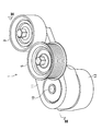
- FIG. 2 is a perspective view showing the auto tensioner of the present invention.
- FIG. 3 is a sectional view taken along line III-III (see FIG. 4) of the auto tensioner of the present invention.
- FIG. 4 is a side view of the auto tensioner according to the present invention (when viewed from the tension pulley side).
- FIG. 5 is a side view showing the auto tensioner of the present invention.
- FIG. 6 is a diagram for explaining various forces acting when a general auto tensioner is used in a belt transmission system.
- FIGS. 7A and 7B are diagrams for explaining various forces that are applied at rest and when the auto tensioner according to the embodiment is used in the belt transmission system.
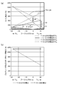
- FIG. 8 shows belt tension (span tension) per belt rib when the T / S ratio is optimized and when the T / S ratio is 1.00 in the belt transmission system having the layout shown in FIG. 7B. And the torque generated in the pulley.
- FIG. 9 is a diagram showing a relationship between the total value of the tension and the slack side tension of the belt per belt rib and the torque generated in the pulley 50 in the pulley 50.
- FIG. 10A shows the belt tension Tb 1 between the pulley 50 and the second tension pulley 3 and between the pulley 50 and the first tension pulley when the T / S ratio is 1.00 and 3.27, respectively.
- FIG. 10A shows the belt tension Tb 1 between the pulley 50 and the second tension pulley 3 and between the pulley 50 and the first tension pulley when the T / S ratio is 1.00 and 3.27, respectively.
- FIG. 6B is a diagram showing a simulation result of the relationship between the belt tension Tb 2 of the belt and the torque generated in the pulley 50
- FIG. 8B shows the pulley 50, the total value of the belt tension side and the slack side tension, and the pulley 50. It is a figure which shows the relationship with the torque which arises in this.
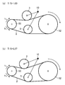
- FIG. 11A shows a case where the T / S ratio is set to 1.0 in the belt transmission system having the auto tensioner according to the embodiment
- FIG. 11B shows the case where the T / S ratio is set to 3.27. It is a figure which shows a layout.
- FIG. 11A shows a case where the T / S ratio is set to 1.0 in the belt transmission system having the auto tensioner according to the embodiment
- FIG. 11B shows the case where the T / S ratio is set to 3.27. It is a figure which shows a layout.
- FIG. 11A shows a case where the T / S ratio is set to 1.0 in the belt
- FIGS. 12 is a diagram showing the relationship between the ratio between the T / S ratio and the optimum value of the T / S ratio and the necessary tension and maximum tension of the belt in the belt transmission system.
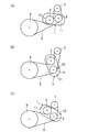
- FIGS. 13A to 13C are views showing a modification of the belt transmission system including the auto tensioner of the present invention.
- FIGS. 14A to 14C are diagrams showing a modification of the belt transmission system including the auto tensioner of the present invention.
- FIGS. 15A to 15C are diagrams showing a modification of the belt transmission system including the auto tensioner of the present invention.
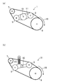
- FIGS. 16A and 16B are views showing a modification of the belt transmission system including the auto tensioner of the present invention.
- FIGS. 17A and 17B are views showing a modification of the belt transmission system including the auto tensioner of the present invention.
- FIG. 1 is a diagram illustrating a belt transmission system including an auto tensioner 1 according to an embodiment of the present invention.
- FIG. 2 is a perspective view showing the auto tensioner 1 in the belt transmission system according to this embodiment, and
- FIG. 3 is a cross-sectional view of the auto tensioner 1 taken along line III-III shown in FIG.
- FIG. 4 is a plan view of the auto tensioner 1 according to the present embodiment as viewed from the tension pulley side.
- FIG. 5 is a side view of the auto tensioner 1 according to the present embodiment.
- the belt transmission system of this embodiment transmits power generated by an internal combustion engine such as an engine and a generator / starter motor, as an example.
- the “generator / starter motor” means a device in which a generator and a starter motor are integrated.
- the belt transmission system includes a crank pulley (first pulley) 9 that transmits power generated by the internal combustion engine, a generator / starter pulley (second pulley) 7 that transmits power generated by the generator / starter motor, and a crank pulley 9. And an endless belt 2 wound between the generator / starter pulley 7 and an auto tensioner 1 for applying a predetermined tension to the belt 2.
- the configuration for applying tension to the belt 2 and the configuration for imparting damping characteristics to the auto tensioner 1 are not particularly limited, an example in which the auto tensioner 1 includes a torsion coil spring will be described.
- the auto tensioner 1 is fixed to a vehicle engine or the like and can swing on the fixing member 13 around the axis of the fixing member 13 on the fixing member 13 having a cylindrical portion. And the first tension pulley 5 and the second tension pulley 3 that are both supported and fixed on the arm 11.
- the distance from the swing center (pivot) 10 of the arm 11 is shorter in the first tension pulley 5 than in the second tension pulley 3. I can't.
- the second tension pulley 3 applies tension to a portion of the belt 2 between the crank pulley 9 and the generator / starter pulley 7 and located on the tight side of the crank pulley 9 during normal operation.
- the tension pulley 5 applies tension to a portion of the belt 2 between the crank pulley 9 and the generator / starter pulley 7 and located on the loose side of the crank pulley 9 during normal operation. With this configuration, the tension of the belt 2 is adjusted to be in an appropriate range.
- the method for supporting the arm 11 on the fixing member 13 is not particularly limited.
- cylindrical portions having different diameters may be provided on both the arms 11 and the cylindrical portions may be fitted to each other.
- the arm 11 includes a cylindrical shaft portion 17 fitted to a cylindrical portion (spindle) 16 of the fixing member 13 and a horizontal direction (the shaft portion 17 and the fixed portion) And an extending portion 19 extending in a direction perpendicular to the axial direction of the member 13.
- the first tension pulley 5 and the second tension pulley 3 are fixed to the extending portion 19 using a fixing tool such as a nut and a screw, respectively.
- a bush 12 is provided between the cylindrical portion 16 of the fixing member 13 and the shaft portion 17 of the arm 11 fitted to the cylindrical portion 16.
- a torsion coil spring 15 having one end locked (connected) to the arm 11 and the other end locked (connected) to the fixing member 13 is provided outside the cylindrical portion 16 and the shaft portion 17 of the fixing member 13. ing.
- the torsion coil spring 15 has an axis substantially coinciding with the axis of the shaft portion 17, and biases the arm 11 in the swinging direction, thereby passing through the first tension pulley 5 and the second tension pulley 3. Tension can be applied to the belt 2.
- the torsion coil spring 15 is preferably made of a metal such as silicon chrome copper or a metal compound.
- the belt 2 may be a flat belt, a toothed belt, a cogged belt, a V belt, or the like.
- the surface of the belt 2 with which the first tension pulley 5 and the second tension pulley 3 are in contact There is no particular limitation on the surface of the belt 2 with which the first tension pulley 5 and the second tension pulley 3 are in contact.
- the first tension pulley 5 is in contact with the outer peripheral surface or inner peripheral surface of the belt 2
- the second tension pulley 3 is You may contact
- the first tension pulley 5 and the second tension pulley 3 may contact the side surface of the belt 2.
- the fixing member 13 is fixed to the engine body or the like by a fixing tool such as a bolt.
- the fixing member 13 and the arm 11 are made of a known metal or the like and can be formed using a mold or the like.
- the direction in which the first tension pulley 5 turns by the force received from the belt 2 and the direction in which the second tension pulley 3 turns by the force received from the belt 2 are the same. Good but may be different.
- the second tension pulley 3 may also turn in the direction to increase the tension of the belt 2.
- the first tension pulley 5 turns in a direction to reduce the tension of the belt 2
- the second tension pulley 3 may also turn in a direction to reduce the tension of the belt 2.
- one of the first tension pulley 5 and the second tension pulley 3 may be designed such that when the tension of the belt 2 is increased, the other decreases the tension of the belt 2.
- the belt transmission system of the present embodiment is designed to reduce excess tension applied to the belt 2 in consideration of the T / S ratio, as will be described in detail later.
- the T / S ratio refers to the arm connected to the first tension pulley 5 (in the example of FIG. 1, the portion from the swing center 10 to the center of the first tension pulley 5 in the arm 11) and the first tension pulley 5.
- the crank pulley 9 when the crank pulley 9 is a driving pulley and when the generator / starter pulley 7 is a driving pulley, the first tension pulley 5 and the second tension pulley 3 respectively.
- the torque of the tension pulley located on the loose side when the maximum torque is generated is larger than the torque of the tension pulley located on the tension side.
- T / S ratio may be set larger than at least 1. Further, it is more preferable that the T / S ratio is set so that the ratio with the optimum value obtained by the method described later is within a predetermined range.
- the belt 2 can be prevented from slipping, and the belt tension can be reduced within a range required for a device to be applied. Therefore, it is possible to extend the life of the belt and extend the life of the pulley by reducing the force applied to the pulley shaft. Further, according to the belt transmission system of the present embodiment, it is possible to improve the fuel consumption.
- the crank pulley 9 is driven when the engine is started and driven (during normal operation), and the belt 2 rotates, for example, clockwise. Then, the portion of the belt 2 that contacts the first tension pulley 5 is on the belt loose side, and the portion that the second tension pulley 3 contacts is on the belt tension side. At this time, the biasing force of the torsion coil spring 15 of the auto tensioner 1 is mainly applied to the belt tension side via the second tension pulley 3. On the other hand, on the belt slack side, the urging force of the torsion coil spring 15 received by the belt 2 is smaller than that on the belt tension side.
- the generator / starter motor when the generator / starter motor is started and driven, the generator / starter pulley 7 is driven, and the belt 2 rotates clockwise.
- the portion of the belt 2 that contacts the first tension pulley 5 is the belt tension side
- the portion that the second tension pulley 3 contacts is the belt loose side.
- the urging force of the torsion coil spring 15 of the auto tensioner 1 is mainly applied to the belt tension side via the first tension pulley 5.
- the urging force of the torsion coil spring 15 of the auto tensioner 1 is distributed while balancing the belt tension side and the belt slack side according to the state of the belt system. Since it can be applied, the swing of the arm 11 can be made extremely small as compared with the conventional belt transmission system, and the occurrence of belt slip can be effectively suppressed.
- the two tension pulleys provided in one auto tensioner 1 respectively apply tension to the belt 2, and therefore, compared to the case where an auto tensioner having one tension pulley is used.
- a large torque can be set with a low tension. Therefore, even if each pulley instantaneously requires a large torque, it is relatively easy to maintain tension.
- the auto tensioner 1 of the present embodiment can be manufactured by combining conventionally used members, and the design change of the belt 2, the crank pulley 9, the generator / starter pulley 7, etc. is unnecessary. Therefore, the belt transmission system of this embodiment can be introduced at low cost.
- the auto tensioner 1 is preferably provided with a member for imparting a unidirectional damping characteristic.
- the damping force can be obtained by friction between the sliding member and the arm 11 or the fixing member 13.
- the damping force is configured by resin or the like on the inner side and the lower side of the torsion coil spring 15.
- a sliding member 24 that slides on a part of the arm 11 is provided.
- the auto tensioner 1 by providing the auto tensioner 1 with a member that imparts a unidirectional damping characteristic, the swing of the arm 11 can be further reduced. Further, with this configuration, it is possible to increase the dynamic tension applied to the belt 2.
- the first tension pulley 5 and the second tension pulley 3 are provided on one arm 11. Therefore, if the auto tensioner 1 of the present embodiment is used, the degree of freedom in design can be increased as compared with the case where auto tensioners having only one tension pulley are provided on the tension side and the loose side of the generator / starter pulley 7 respectively. Is possible.
- FIGS. 6A and 6B are diagrams for explaining various forces acting when a general auto tensioner is used in a belt transmission system.
- FIGS. 7A and 7B show the auto tensioner 1 of the present embodiment as a belt. It is a figure explaining the various force which acts at the time of a stationary and driving
- the auto tensioner 1 includes two tension pulleys 3 and 5 and can appropriately change the above-described T / S ratio.
- T / S ratio By changing the T / S ratio, the sensitivity of the tension to the torque can be changed, and the relationship between the pulley torque shown in the torque-span tension diagram (FIG. 8 described later) and the span tension of the belt 2 can be changed.
- the belt transmission system in consideration of the T / S ratio and the design method thereof will be described in detail.
- Hub load P 2 ⁇ Tb ⁇ sin ( ⁇ / 2)
- Length of arm at moment m L ⁇ sin ( ⁇ )
- L is the arm length (mm) from the swing center 100 of the arm to the center position of the tension pulley 26
- Tb is between the pulley 30 and the tension pulley 26, and between the pulley 50 and the tension pulley 26.
- ⁇ is the winding angle of the belt 2 on the tension pulley 26
- ⁇ is an angle formed by an input angle line from the belt 2 to the tension pulley 26 and a line connecting the swing center 100 of the arm.
- Tr is a torque generated at the swing center 100 of the arm.
- the first tension pulley 5 of the auto tensioner 1 of the present embodiment is disposed between the pulley 50 and the pulley 20, and the second tension pulley 3 is connected to the pulley 50.
- Tr 2 ⁇ Tb ⁇ [L 1 ⁇ sin ( ⁇ 1/2) ⁇ sin ( ⁇ 1) + L 2 ⁇ sin ( ⁇ 2/2) ⁇ sin ( ⁇ 2)] ⁇ (1) Further, as shown in FIG.
- Tr A and Tr G are values required in an actually designed layout.
- Tt is the tension on the tension side of the belt 2
- Ts is the tension on the loose side of the belt 2
- ⁇ ′ is an apparent coefficient of friction between the belt 2 and the pulley 50
- ⁇ is the belt winding angle at the pulley 50. is there.
- the tension Ts on the loose side is calculated using Euler's equation, and the tension on the tension side Tt is calculated as a value obtained by adding an effective tension to Ts.
- Tb 2A Tb 1A + Tr A / R (3)
- R is the radius of the pulley 50.
- Tb 1A Tr A / R (e ⁇ ′ ⁇ ⁇ 1) (4) It becomes.
- Tb 1G Tb 2G + Tr G / R (6)
- Tb 2G Tr G / R (e ⁇ ′ ⁇ ⁇ 1) (7) It becomes.
- the absolute value of Tb 2A -Tb 2G and the absolute value of Tb 1A -Tb 1G may be the numerator, and the smaller value may be the denominator as the optimum value of the T / S ratio.
- the tension side tension Tt and the slack side tension Ts of the belt 2 are obtained for each of the pulleys 20 and 30 similarly to the pulley 50 by using Euler's equation.
- the slack side tension when the forward rotation torque and the reverse rotation torque generated in each of the pulleys 20 and 30 are maximum values is calculated as the necessary tension.
- the optimum T / S ratio is calculated using the highest necessary tension value among the necessary tensions calculated for each pulley. To do.
- T / S ratio ⁇ L 1 ⁇ sin ( ⁇ 1/2) ⁇ sin ( ⁇ 1) ⁇ / ⁇ L 2 ⁇ sin ( ⁇ 2/2) ⁇ sin ( ⁇ 2) ⁇ ⁇ (8)
- L 1 is the arm length (first arm length) from the swing center 10 of the arm 11 to the center position of the second tension pulley 3
- ⁇ 1 is the second tension pulley.
- 3 is a belt winding angle at 3
- ⁇ 1 is a hub load angle at the second tension pulley 3.
- L 2 is the arm length (second arm length) from the swing center 10 of the arm 11 to the center position of the first tension pulley 5, and ⁇ 2 is the belt winding around the first tension pulley 5.
- An angle, and ⁇ 2 is a hub load angle in the first tension pulley 5.
- the T / S ratio is determined by L 1 , ⁇ 1 , ⁇ 1 , L 2 , ⁇ 2, and ⁇ 2 , so the T / S ratio approaches the optimum value obtained previously.
- the inventor of the present application actually calculated an optimum T / S ratio for a belt transmission system in which a belt is wound between a pulley (driven pulley) 50 and a driving pulley.
- FIG. 8 shows a case where the T / S ratio is optimized and the T / S ratio is 1.00 in the belt transmission system having the layout shown in Table 2 and FIGS. 11A and 11B described later.
- FIG. 9 is a diagram showing the relationship between the belt tension (span tension) per belt rib and the torque generated in the pulley 50, and FIG. 9 shows the total value of the tension on the belt and the tension on the slack side per belt rib in the pulley 50 ( That is, it is a diagram showing the relationship between the generator and starter motor axial force) and the torque generated in the pulley 50.
- Table 2 shows the layout of the belt transmission system and the calculation results such as required tension and T / S ratio. 8 and 9 show theoretical values (optimal values) calculated under the conditions shown in Table 2.
- FIG. 10A shows the belt tension Tb1 between the pulley 50 and the second tension pulley 3 and the pulley 50 and the first tension pulley when the T / S ratio is 1.00 and 3.27, respectively.
- FIG. 6B is a diagram showing a simulation result of the relationship between the belt tension Tb2 between the belt and the torque generated in the pulley 50.
- FIG. 5B shows the pulley 50, the total value of the belt tension side and the slack side tension, and the pulley 50. It is a figure which shows the relationship with the torque which arises in this.
- FIGS. 8 and 9 and FIGS. 10A and 10B are different in the unit of the vertical axis, the same simulation results are shown.
- the maximum value of the driving torque Tr A 28 (N ⁇ m) setting the maximum value of the driving torque Tr G to 11 (N ⁇ m), and when Tr A is 28 (N ⁇ m), the pulley 50-
- the necessary tension Tb 1A of the belt 2 between the second tension pulleys 3 is 102.8 (N ⁇ m)
- the Tb 2A of the belt 2 between the pulleys 50 and the first tension pulley 5 is 1036.1 (N ⁇ M).
- Tr G When Tr G is 11 (N ⁇ m), the necessary tension Tb 2G of the belt 2 between the pulley 50 and the first tension pulley 5 is 40.4 (N ⁇ m), and the pulley 50-second The Tb 1G of the belt 2 between the tension pulleys 3 was 407.0 (N ⁇ m).
- ⁇ Tb 1 is 304.2 (N ⁇ m)
- ⁇ Tb 2 is 995.7 (N ⁇ m)
- an appropriate T / S ratio can be calculated to be 3.27. It was.
- the tension Tb 1 of the belt 2 between the pulley 50 and the second tension pulley 3 increases linearly as Tr A decreases and Tr G increases. It can be seen that by optimizing the T / S ratio, the T / S can be significantly reduced within a necessary range as compared with, for example, 1.00. Further, the tension Tb 2 of the belt 2 between the pulley 50 and the first tension pulley 5 decreases linearly as Tr A decreases and Tr G increases, but the T / S ratio is optimized. Thus, it can be seen that the T / S can be significantly reduced as compared to 1.00.
- the belt tension can be reduced to the necessary and sufficient range to extend the belt life and the force applied to the pulley shaft. And the life of the pulley can be extended.
- FIGS. 11A and 11B show a case where the T / S ratio is set to 1.00 and the T / S ratio is set to 3.27 in the belt transmission system having the auto tensioner 1 of the present embodiment.
- FIG. In the belt transmission system shown in FIGS. 11A and 11B, the belt 2 is wound between a pulley (driven pulley) 50 and a driving pulley 52, and the auto tensioner 1 is provided.
- the pulley 50 can be compared with the case where the T / S ratio is 1.00.
- a tension reduction effect 55 of about 248 (N) is obtained, and when a driven torque Tr G of 11 (N) is generated in the pulley 50, between the pulley 50 and the second tension pulley 3 It was confirmed that a tension reduction effect 53 of about 346 (N) was obtained.
- the slip region 57 is not entered in either case where the driving torque Tr A is the maximum value or the case where the driven torque Tr G torque is the maximum value. In the range, it was confirmed that the tension of the belt 2 could be around the minimum necessary tension 51.
- the belt transmission system of the present embodiment it is preferable to optimize the T / S ratio as much as possible.
- the T / S ratio cannot be optimized due to layout reasons, If the torque of the tension pulley located on the loose side when the maximum torque is generated among the first tension pulley 5 and the second tension pulley 3 is made larger than the torque of the tension pulley located on the tension side Good. Thereby, extra tension applied to the belt 2 can be reduced.
- FIG. 12 is a diagram showing the relationship between the ratio between the T / S ratio and the optimum value of the T / S ratio, the necessary tension of the belt, and the maximum tension in the belt transmission system. This figure shows the results when the T / S ratio is changed under the conditions shown in FIG.
- the value of (T / S ratio) / (optimal value of T / S ratio) is preferably set to 0.3 or more and 2.7 or less.
- the number of ribs of the belt 2 used in the belt transmission system is set to 5 or 6, and the value of (T / S ratio) / (optimum value of T / S ratio) exceeds 2.7.
- the value of (T / S ratio) / (optimum value of T / S ratio) is preferably 2.7 or less.
- the starter motor is started most severely under the operating condition. Therefore, it is preferable that the layout of the belt transmission system satisfies the conditions for starting the starter motor.
- the torque applied to the second tension pulley 3 is preferably larger than the torque applied to the first tension pulley 5.
- a pulley closer to the swing center 10 of the arm 11 is arranged on the first tension pulley 5 side, and a pulley farther from the swing center 10 of the arm 11 is placed on the second side.
- the tension pulley 3 may be used.
- the winding angle of the belt 2 in the second tension pulley 3 may be larger than the winding angle of the belt 2 in the first tension pulley 5. Further, when an angle formed by an input angle line from the belt 2 to the tension pulley and a line connecting the swing center 10 of the arm 11 is referred to as a hub load angle (HLA; that is, the above-described hub load angle ⁇ ), The HLA in the first tension pulley 5 may be further from 90 degrees than the HLA in the tension pulley 3.
- HLA hub load angle
- the layout is not particularly limited as long as it is designed in consideration of the T / S ratio.
- the T / S ratio is preferably greater than 1, for example, and less than or equal to the optimum value obtained by calculation.
- the two tension pulleys 3, 5 provided in one auto tensioner 1 apply tension to the tension side and the loose side of the belt 2, and the first tension pulley 5 and the second tension by the force received from the belt 2.
- the pulley 3 may turn in the same direction.
- the second tension pulley 3 may also turn in a direction to increase the tension of the belt 2. This configuration is preferable because the T / S ratio in the auto tensioner 1 can be easily optimized.
- the generator / starter pulley 7 when the generator / starter pulley 7 is a driving pulley and the crank pulley 9 is a driven pulley, the generator / starter pulley 7 is a driven pulley and the crank pulley 9 is a driving pulley.
- the T / S ratio can be set so that the swing of the arm 11 is reduced. Therefore, for example, in the belt transmission system of the present embodiment, the swing of the arm 11 is suppressed to be small and the durability is further improved as compared with the belt transmission systems described in the cited documents 2 and 3.
- the first tension pulley 5 is wound around the inner peripheral surface side of the belt 2 and the second tension pulley is wound around the back surface side of the belt 2.
- the first tension pulley 5 and the second tension pulley 3 may be wound around the same surface side of the belt 2 by appropriately adding an idler pulley.
- the rotation direction 18 of the belt 2 may be clockwise or counterclockwise. If an appropriate T / S ratio is obtained based on the magnitudes of Tr A and Tr G , the same effect can be obtained regardless of the belt rotation direction. Moreover, you may use the auto tensioner 1 of this embodiment also for the belt transmission system which can change the rotation direction 18 of the belt 2 to both a forward direction and a reverse direction.
- modifications of the belt transmission system of the present embodiment will be collectively shown below.
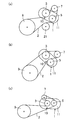
- FIGS. 13A to 13C and FIGS. 14A to 14C are diagrams showing modifications of the belt transmission system including the auto tensioner of the present invention.
- 13 and 14 the center of the cylindrical portion (spindle) 16 of the fixing member 13 coincides with the swing center 10 of the arm.
- the belt 2 rotates clockwise when the engine is started and driven.
- FIGS. 13A to 13C, 14B and 14C the winding angle of the belt 2 and the arrangement of the pulleys in the first tension pulley 5 or the second tension pulley 3 are shown in FIG. The example may be changed. Further, as shown in FIG. 14A, another pulley such as an idler pulley 21 may be appropriately added to the belt transmission system.
- another pulley such as an idler pulley 21 may be appropriately added to the belt transmission system.
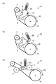
- 15 (a) to 15 (c), 16 (a), 16 (b), 17 (a), and 17 (b) are diagrams showing another modification of the belt transmission system including the auto tensioner of the present invention. is there.
- the auto tensioner 31 shown in FIG. 15B includes an extension spring 25 having one end fixed and the other end connected to the arm 11.
- the rotation direction 18 of the belt 2 may be clockwise or counterclockwise in FIGS. 15 (a) to 15 (c), but can be switched between forward and reverse directions. Also good.
- a belt transmission system capable of switching the rotation direction of the belt 2 is preferably used for a plate compactor, for example.
- both the first tension pulley 5 and the second tension pulley 3 may be in contact with the outer peripheral surface of the belt.
- the first tension pulley 5 and the second tension pulley 3 are used. May be provided on the arm 11.
- the hydraulic damper 27 applies an appropriate reaction force to the arm 11 according to the swing of the arm 11. Since the hydraulic damper 27 can apply a larger force than the spring, the hydraulic tensioner can be preferably used for applications in which the belt tension is relatively large.
- the first tension pulley 5 and the second tension pulley 3 are opposite to each other across the swing center 10 of the arm 11. It may be arranged on the side. In the auto tensioner 1, both the first tension pulley 5 and the second tension pulley 3 are in contact with the outer peripheral surface of the belt 2.
- the first tension pulley 5 and the second tension pulley 3 are both in contact with the inner peripheral surface of the belt 2. Also good.
- the turning directions of the first tension pulley 5 and the second tension pulley 3 may be the same or different from each other. Further, when the first tension pulley 5 turns in a direction to increase the tension of the belt 2, the second tension pulley 3 may also turn in a direction to increase the tension of the belt 2.
- the belt transmission system does not necessarily have an internal combustion engine and a generator / starter motor, and may be a system that transmits power in a device other than a vehicle.
- tension pulleys arranged between two drive pulleys that can be switched between the driven side and the drive side may be supported by a common arm, or the two tension pulleys have a common swing center. It may be connected to the other arm.
- the torque of the tension pulley located on the loose side is larger than the torque of the tension pulley located on the tension side.
- the tension of the belt 2 is reduced within a range exceeding the necessary tension, and the force applied to the pulley shaft is also reduced.
- the lifespan of the belt 2 and the pulley is extended, and fuel consumption is improved.
- tensile_strength required for the belt 2 is hold
- the T / S ratio is set to be greater than at least 1, and more preferably, the value of (T / S ratio) / (optimum value of T / S ratio) is 0.3 or more.
- the belt tension can be greatly reduced without changing the belt width. Further, the swing of the arm 11 can be suppressed to a small value both when the crank pulley 9 is driven and when the generator / starter pulley 7 is driven.
- the auto tensioner according to an example of the present invention can be applied to various vehicles having an internal combustion engine, for example.
Landscapes
- Engineering & Computer Science (AREA)
- General Engineering & Computer Science (AREA)
- Mechanical Engineering (AREA)
- Chemical & Material Sciences (AREA)
- Combustion & Propulsion (AREA)
- Devices For Conveying Motion By Means Of Endless Flexible Members (AREA)
Abstract
Description
-オートテンショナの構成-
図1は、本発明の一実施形態に係るオートテンショナ1を備えたベルト伝動システムを示す図である。図2は、本実施形態に係るベルト伝動システムにおけるオートテンショナ1を示す斜視図であり、図3は、図4に示すIII-III線におけるオートテンショナ1の断面図である。図4は、本実施形態に係るオートテンショナ1をテンションプーリ側から見た平面図である。図5は、本実施形態に係るオートテンショナ1の側面図である。
図6は、一般的なオートテンショナをベルト伝動システムに用いた場合に働く各種の力を説明する図であり、図7(a)、(b)は、それぞれ本実施形態のオートテンショナ1をベルト伝動システムに用いた場合の、静止時及び運転時に働く各種の力を説明する図である。
ハブロードP=2 ×Tb × sin(θ/2)、
モーメントにおける腕の長さm=L × sin(α)、
Tr=P ×m=2 × Tb × L × sin(θ/2) × sin(α)
となる。上式において、Lはアームの揺動中心100からテンションプーリ26の中心位置までのアーム長さ(mm)であり、Tbはプーリ30とテンションプーリ26との間、及びプーリ50とテンションプーリ26との間におけるベルト2の張力(N)である。また、θはテンションプーリ26におけるベルト2の巻き付け角度であり、αはベルト2からテンションプーリ26への入力角度線とアームの揺動中心100とを結んだ線とが成す角度である。Trはアームの揺動中心100に生じるトルクである。
Tr=2 ×Tb × [L1 × sin(θ1/2)× sin(α1) + L2 × sin(θ2/2) × sin(α2)] ・・・(1)
また、図7(b)に示すように、本実施形態のオートテンショナ1を設置したベルト伝動システムを運転させる場合、ベルト2が右回りに回転するとすると、プーリ50が駆動する際にはこのプーリ50に右回りのトルク(逆転トルク)TrAが生じる。また、プーリ50が従動側である場合には左回りのトルク(正転トルク)TrGが生じる。プーリ50がジェネレータ/スタータプーリ7であるとすると、TrA>TrGとなる。これは、通常の内燃機関のジェネレータ/スタータシステムでは、スタータ始動時にジェネレータ/スタータプーリ7に最も大きいトルクが発生するためである。
TrA: Tb2A/Tb1A=eμ'θ ・・・(2)
Tb2A=Tb1A+TrA/R ・・・(3)
ここで、Rはプーリ50の半径である。
Tb1A=TrA/R(eμ'θ-1) ・・・(4)
となる。
TrG: Tb1G/Tb2G=eμ'θ ・・・(5)
Tb1G=Tb2G+TrG/R ・・・(6)
プーリ50-第1のテンションプーリ5間のベルトの必要張力Tb2Gは、
Tb2G=TrG/R(eμ'θ-1) ・・・(7)
となる。

T/S比={L1 × sin(θ1/2) × sin(α1)}/{L2× sin(θ2/2) × sin(α2)} ・・・(8)
式(8)において、L1はアーム11の揺動中心10から第2のテンションプーリ3の中心位置までのアーム長さ(第1のアーム長さ)であり、θ1は第2のテンションプーリ3におけるベルト巻き付け角度であり、α1は第2のテンションプーリ3におけるハブロード角である。また、L2はアーム11の揺動中心10から第1のテンションプーリ5の中心位置までのアーム長さ(第2のアーム長さ)であり、θ2は第1のテンションプーリ5におけるベルト巻き付け角度であり、α2は第1のテンションプーリ5におけるハブロード角である。

図13(a)~(c)及び図14(a)~(c)は、本発明のオートテンショナを含むベルト伝動システムの変形例を示す図である。図13及び図14では、固定部材13の筒状部(スピンドル)16の中心がアームの揺動中心10と一致している。ここでは、エンジン始動時及び駆動時にベルト2が右回りに回転する例を示す。
2 ベルト
3 第2のテンションプーリ
5 第1のテンションプーリ
7 ジェネレータ/スタータプーリ
9 クランクプーリ
11 アーム
12 ブッシュ
13 固定部材
16 筒状部
17 軸部
18 ベルトの回転方向
19 延伸部
20、30、50 プーリ
21 アイドラプーリ
24 摺動部材
26 テンションプーリ
27 油圧ダンパー
51 最低必要張力
52 駆動プーリ
53、55 張力低減効果
57 スリップ領域
Claims (6)
- 第1の動力を伝達する第1のプーリと、
第2の動力を伝達する第2のプーリと、
前記第1のプーリと前記第2のプーリとの間に巻き掛けられた無端状のベルトと、
前記ベルトのうち、前記第1のプーリと前記第2のプーリとの間であって通常運転時における前記第1のプーリの緩み側に位置する部分に張力を与える第1のテンションプーリと、固定部材と、前記固定部材上に、前記固定部材の軸回り方向に揺動可能に設けられたアームとを有するオートテンショナと、
前記ベルトのうち、前記第1のプーリと前記第2のプーリとの間であって通常運転時における前記第1のプーリの張り側に位置する部分に張力を与える第2のテンションプーリとを備え、
前記第1のプーリが駆動プーリである時、及び前記第2のプーリが駆動プーリである時のそれぞれにおいて、前記第1のテンションプーリ及び第2のテンションプーリのうち、最大のトルクが発生する際の緩み側に位置するテンションプーリのトルクは、張り側に位置するテンションプーリのトルクより大きいベルト伝動システム。 - 請求項1に記載のベルト伝動システムにおいて、
前記第2のテンションプーリにおける第1のアーム長さをL1、前記第2のテンションプーリにおけるベルト巻き付け角度をθ1、前記第2のテンションプーリ側のハブロード角をα1とし、前記第1のテンションプーリにおける第2のアーム長さをL2、前記第1のテンションプーリにおけるベルト巻き付け角度をθ2、前記第1のテンションプーリ側のハブロード角をα2とし、
最大のトルクが発生する際の緩み側に位置するテンションプーリが前記第2のテンションプーリである場合、
{L1 × sin(θ1/2) × sin(α1)}/{L2× sin(θ2/2) × sin(α2)}で求められるT/S比は1より大きいベルト伝動システム。 - 請求項2に記載のベルト伝動システムにおいて、
前記T/S比と、前記T/Sの計算上の最適値との比が所定の範囲内にあり、
前記T/S比の最適値は、前記第1のプーリ及び前記第2のプーリにおいて、正転トルクが最大である場合のベルト緩み側の必要張力が大きい方の必要張力の値と、逆転トルクが最大である場合のベルト緩み側の必要張力が大きい方の必要張力の値とを用いて算出されることを特徴とするベルト伝動システム。 - 請求項2又は3に記載のベルト伝動システムにおいて、
前記第1のプーリに生じる正転トルクをTrG、逆転トルクをTrAとするとき、TrAが最大である場合の前記第1のプーリ-前記第2のテンションプーリ間のベルト張力の必要張力Tb1Aと、前記第1のプーリ-前記第1のテンションプーリ間のベルト張力Tb2A、及びTrGが最大である場合の前記第1のプーリ-前記第2のテンションプーリ間のベルト張力Tb1Gと、前記第1のプーリ-前記第1のテンションプーリ間のベルト張力の必要張力Tb2Gとを用い、Tb2A-Tb2Gの絶対値及びTb1A-Tb1Gの絶対値のうち大きい方を分子とし、小さい方を分母とした値を前記T/S比の最適値とすることを特徴とするベルト伝動システム。 - 請求項2~4のうちいずれか1つに記載のベルト伝動システムにおいて、
前記T/S比と前記T/S比の最適値との比が0.3以上2.7以下であることを特徴とするベルト伝動システム。 - 請求項1~5のうちいずれか1つに記載のベルト伝動システムにおいて、
前記第2のテンションプーリは、前記アーム上に支持されていることを特徴とするベルト伝動システム。
Priority Applications (5)
| Application Number | Priority Date | Filing Date | Title |
|---|---|---|---|
| KR1020177031725A KR20180006375A (ko) | 2015-05-08 | 2016-04-21 | 벨트 전동 시스템 |
| DE112016002094.5T DE112016002094T5 (de) | 2015-05-08 | 2016-04-21 | Riementransmissionssystem |
| CN201680022784.5A CN107532690B (zh) | 2015-05-08 | 2016-04-21 | 带传动系统 |
| JP2016530261A JP6026058B1 (ja) | 2015-05-08 | 2016-04-21 | ベルト伝動システム |
| US15/804,853 US10184549B2 (en) | 2015-05-08 | 2017-11-06 | Belt transmission system |
Applications Claiming Priority (2)
| Application Number | Priority Date | Filing Date | Title |
|---|---|---|---|
| JP2015095991 | 2015-05-08 | ||
| JP2015-095991 | 2015-05-08 |
Related Child Applications (1)
| Application Number | Title | Priority Date | Filing Date |
|---|---|---|---|
| US15/804,853 Continuation US10184549B2 (en) | 2015-05-08 | 2017-11-06 | Belt transmission system |
Publications (1)
| Publication Number | Publication Date |
|---|---|
| WO2016181619A1 true WO2016181619A1 (ja) | 2016-11-17 |
Family
ID=57247913
Family Applications (1)
| Application Number | Title | Priority Date | Filing Date |
|---|---|---|---|
| PCT/JP2016/002143 Ceased WO2016181619A1 (ja) | 2015-05-08 | 2016-04-21 | ベルト伝動システム |
Country Status (6)
| Country | Link |
|---|---|
| US (1) | US10184549B2 (ja) |
| JP (1) | JP6026058B1 (ja) |
| KR (1) | KR20180006375A (ja) |
| CN (1) | CN107532690B (ja) |
| DE (1) | DE112016002094T5 (ja) |
| WO (1) | WO2016181619A1 (ja) |
Cited By (1)
| Publication number | Priority date | Publication date | Assignee | Title |
|---|---|---|---|---|
| WO2018155336A1 (ja) * | 2017-02-21 | 2018-08-30 | 株式会社デンソー | 回転電機制御装置、及び、内燃機関制御装置 |
Families Citing this family (4)
| Publication number | Priority date | Publication date | Assignee | Title |
|---|---|---|---|---|
| DE112015002405B4 (de) * | 2014-05-22 | 2022-06-15 | Bando Chemical Industries, Ltd. | Riementransmissionssystem |
| DE102015105655B3 (de) * | 2015-04-14 | 2016-07-07 | Netzsch-Feinmahltechnik Gmbh | Spannvorrichtung für eine Rührwerkskugelmühle mit Riemen- oder Kettenantrieb und Rührwerkskugelmühle |
| KR102552020B1 (ko) * | 2018-10-19 | 2023-07-05 | 현대자동차 주식회사 | 하이브리드 차량용 텐셔너 |
| US20250035513A1 (en) * | 2021-06-30 | 2025-01-30 | Mitsuboshi Belting Ltd. | Calculation Control Method for Predicted Value of Jumping Torque of Toothed Belt |
Citations (3)
| Publication number | Priority date | Publication date | Assignee | Title |
|---|---|---|---|---|
| JP2001059555A (ja) * | 1999-08-20 | 2001-03-06 | Denso Corp | 内燃機関用ベルト伝動システム |
| JP2001193807A (ja) * | 2000-01-12 | 2001-07-17 | Litens Automotive Gmbh | 可撓性エンドレス駆動要素用張力調整装置 |
| DE102008058969A1 (de) * | 2008-11-25 | 2010-05-27 | Bayerische Motoren Werke Aktiengesellschaft | Zugmittelspanneinrichtung |
Family Cites Families (14)
| Publication number | Priority date | Publication date | Assignee | Title |
|---|---|---|---|---|
| JPH1182652A (ja) * | 1997-09-16 | 1999-03-26 | Ntn Corp | ベルト伝動装置におけるベルトの張力調整装置 |
| EP1340005B1 (en) * | 2000-10-03 | 2008-04-02 | The Gates Corporation | Motor/generator and accessory belt drive system |
| AU2001296474A1 (en) * | 2000-10-03 | 2002-04-15 | The Gates Corporation | Accessory and motor/generator belt drive tensioner |
| US6942589B2 (en) | 2002-02-08 | 2005-09-13 | Dayco Products, Llc | Offset starter generator drive utilizing a fixed-offset dual-arm pivoted tensioner |
| US6652401B2 (en) * | 2002-02-11 | 2003-11-25 | The Gates Corporation | Method of tuning a belt drive system |
| US6896632B2 (en) * | 2002-02-21 | 2005-05-24 | The Gates Corporation | Belt drive cantilever tensioner |
| JP4315362B2 (ja) | 2002-08-08 | 2009-08-19 | バンドー化学株式会社 | ベルト伝動装置 |
| US20050181901A1 (en) * | 2004-02-13 | 2005-08-18 | Chang-Hyun Shin | Double action belt tensioner |
| JP4356638B2 (ja) * | 2005-03-31 | 2009-11-04 | 株式会社デンソー | 車両用交流発電機の駆動装置 |
| JP5167998B2 (ja) * | 2008-07-16 | 2013-03-21 | セイコーエプソン株式会社 | ベルト駆動装置及び記録装置 |
| US20140357436A1 (en) * | 2013-06-04 | 2014-12-04 | Shimano Inc. | Bicycle chain tensioner |
| US9140338B2 (en) * | 2014-02-06 | 2015-09-22 | Gates Corporation | Tensioner |
| US9920819B2 (en) * | 2014-02-06 | 2018-03-20 | Gates Corporation | Tensioner |
| DE112015002405B4 (de) * | 2014-05-22 | 2022-06-15 | Bando Chemical Industries, Ltd. | Riementransmissionssystem |
-
2016
- 2016-04-21 KR KR1020177031725A patent/KR20180006375A/ko not_active Ceased
- 2016-04-21 WO PCT/JP2016/002143 patent/WO2016181619A1/ja not_active Ceased
- 2016-04-21 JP JP2016530261A patent/JP6026058B1/ja not_active Expired - Fee Related
- 2016-04-21 CN CN201680022784.5A patent/CN107532690B/zh not_active Expired - Fee Related
- 2016-04-21 DE DE112016002094.5T patent/DE112016002094T5/de not_active Withdrawn
-
2017
- 2017-11-06 US US15/804,853 patent/US10184549B2/en active Active
Patent Citations (3)
| Publication number | Priority date | Publication date | Assignee | Title |
|---|---|---|---|---|
| JP2001059555A (ja) * | 1999-08-20 | 2001-03-06 | Denso Corp | 内燃機関用ベルト伝動システム |
| JP2001193807A (ja) * | 2000-01-12 | 2001-07-17 | Litens Automotive Gmbh | 可撓性エンドレス駆動要素用張力調整装置 |
| DE102008058969A1 (de) * | 2008-11-25 | 2010-05-27 | Bayerische Motoren Werke Aktiengesellschaft | Zugmittelspanneinrichtung |
Cited By (1)
| Publication number | Priority date | Publication date | Assignee | Title |
|---|---|---|---|---|
| WO2018155336A1 (ja) * | 2017-02-21 | 2018-08-30 | 株式会社デンソー | 回転電機制御装置、及び、内燃機関制御装置 |
Also Published As
| Publication number | Publication date |
|---|---|
| JPWO2016181619A1 (ja) | 2017-05-25 |
| JP6026058B1 (ja) | 2016-11-16 |
| CN107532690A (zh) | 2018-01-02 |
| DE112016002094T5 (de) | 2018-02-15 |
| US20180058551A1 (en) | 2018-03-01 |
| US10184549B2 (en) | 2019-01-22 |
| CN107532690B (zh) | 2020-04-10 |
| KR20180006375A (ko) | 2018-01-17 |
Similar Documents
| Publication | Publication Date | Title |
|---|---|---|
| WO2015177997A1 (ja) | ベルト伝動システム | |
| JPWO2015177997A6 (ja) | ベルト伝動システム | |
| JP6026058B1 (ja) | ベルト伝動システム | |
| CN102472372B (zh) | 双张紧器组件 | |
| KR102354424B1 (ko) | 텐셔너 및 방법 | |
| JP5162591B2 (ja) | ツーウェイダンパーを有するテンショナ | |
| JP3683531B2 (ja) | ダンピング機構を備えたテンショナ | |
| EP2558749B1 (en) | Isolator | |
| CN105518340B (zh) | 阻尼增强且具有位于基部杯状件构型上的臂的张紧器 | |
| EP3322918B1 (en) | Tensioner with secondary damping | |
| US20170074375A1 (en) | Endless drive arrangement and improved two-armed tensioning system for same | |
| JP2009008109A (ja) | プーリ構造体、及び、これを用いた補機駆動システム | |
| JP2019529828A (ja) | テンショナ | |
| US10794455B2 (en) | Tensioner | |
| WO2021187482A1 (ja) | 補機ベルト用オートテンショナ、および補機駆動システム | |
| JP2022505862A (ja) | テンショナ | |
| US10876604B2 (en) | Pulley apparatus for driving-driven rotating machine | |
| JP6457222B2 (ja) | 摩擦式オートテンショナ | |
| CN109690133A (zh) | 环式传动装置和用于环式传动装置的改进的双臂张紧系统 | |
| JP2009236158A (ja) | オートテンショナ | |
| EP4590981A1 (en) | Dual arm tensioner with dynamic pivot | |
| JP2015108394A (ja) | オートテンショナ | |
| JPH08363U (ja) | ベルト式無段変速機 |
Legal Events
| Date | Code | Title | Description |
|---|---|---|---|
| ENP | Entry into the national phase |
Ref document number: 2016530261 Country of ref document: JP Kind code of ref document: A |
|
| 121 | Ep: the epo has been informed by wipo that ep was designated in this application |
Ref document number: 16792349 Country of ref document: EP Kind code of ref document: A1 |
|
| ENP | Entry into the national phase |
Ref document number: 20177031725 Country of ref document: KR Kind code of ref document: A |
|
| WWE | Wipo information: entry into national phase |
Ref document number: 112016002094 Country of ref document: DE |
|
| 122 | Ep: pct application non-entry in european phase |
Ref document number: 16792349 Country of ref document: EP Kind code of ref document: A1 |