WO2016181515A1 - 磁気エンコーダ及び転がり軸受 - Google Patents
磁気エンコーダ及び転がり軸受 Download PDFInfo
- Publication number
- WO2016181515A1 WO2016181515A1 PCT/JP2015/063698 JP2015063698W WO2016181515A1 WO 2016181515 A1 WO2016181515 A1 WO 2016181515A1 JP 2015063698 W JP2015063698 W JP 2015063698W WO 2016181515 A1 WO2016181515 A1 WO 2016181515A1
- Authority
- WO
- WIPO (PCT)
- Prior art keywords
- slinger
- cylindrical portion
- protruding
- cylindrical
- inner ring
- Prior art date
- Legal status (The legal status is an assumption and is not a legal conclusion. Google has not performed a legal analysis and makes no representation as to the accuracy of the status listed.)
- Ceased
Links
Images


Classifications
-
- F—MECHANICAL ENGINEERING; LIGHTING; HEATING; WEAPONS; BLASTING
- F16—ENGINEERING ELEMENTS AND UNITS; GENERAL MEASURES FOR PRODUCING AND MAINTAINING EFFECTIVE FUNCTIONING OF MACHINES OR INSTALLATIONS; THERMAL INSULATION IN GENERAL
- F16C—SHAFTS; FLEXIBLE SHAFTS; ELEMENTS OR CRANKSHAFT MECHANISMS; ROTARY BODIES OTHER THAN GEARING ELEMENTS; BEARINGS
- F16C41/00—Other accessories, e.g. devices integrated in the bearing not relating to the bearing function as such
- F16C41/007—Encoders, e.g. parts with a plurality of alternating magnetic poles
-
- F—MECHANICAL ENGINEERING; LIGHTING; HEATING; WEAPONS; BLASTING
- F16—ENGINEERING ELEMENTS AND UNITS; GENERAL MEASURES FOR PRODUCING AND MAINTAINING EFFECTIVE FUNCTIONING OF MACHINES OR INSTALLATIONS; THERMAL INSULATION IN GENERAL
- F16C—SHAFTS; FLEXIBLE SHAFTS; ELEMENTS OR CRANKSHAFT MECHANISMS; ROTARY BODIES OTHER THAN GEARING ELEMENTS; BEARINGS
- F16C33/00—Parts of bearings; Special methods for making bearings or parts thereof
- F16C33/72—Sealings
- F16C33/76—Sealings of ball or roller bearings
- F16C33/78—Sealings of ball or roller bearings with a diaphragm, disc, or ring, with or without resilient members
- F16C33/7816—Details of the sealing or parts thereof, e.g. geometry, material
- F16C33/783—Details of the sealing or parts thereof, e.g. geometry, material of the mounting region
-
- F—MECHANICAL ENGINEERING; LIGHTING; HEATING; WEAPONS; BLASTING
- F16—ENGINEERING ELEMENTS AND UNITS; GENERAL MEASURES FOR PRODUCING AND MAINTAINING EFFECTIVE FUNCTIONING OF MACHINES OR INSTALLATIONS; THERMAL INSULATION IN GENERAL
- F16C—SHAFTS; FLEXIBLE SHAFTS; ELEMENTS OR CRANKSHAFT MECHANISMS; ROTARY BODIES OTHER THAN GEARING ELEMENTS; BEARINGS
- F16C33/00—Parts of bearings; Special methods for making bearings or parts thereof
- F16C33/72—Sealings
- F16C33/76—Sealings of ball or roller bearings
- F16C33/78—Sealings of ball or roller bearings with a diaphragm, disc, or ring, with or without resilient members
- F16C33/7869—Sealings of ball or roller bearings with a diaphragm, disc, or ring, with or without resilient members mounted with a cylindrical portion to the inner surface of the outer race and having a radial portion extending inward
- F16C33/7879—Sealings of ball or roller bearings with a diaphragm, disc, or ring, with or without resilient members mounted with a cylindrical portion to the inner surface of the outer race and having a radial portion extending inward with a further sealing ring
- F16C33/7883—Sealings of ball or roller bearings with a diaphragm, disc, or ring, with or without resilient members mounted with a cylindrical portion to the inner surface of the outer race and having a radial portion extending inward with a further sealing ring mounted to the inner race and of generally L-shape, the two sealing rings defining a sealing with box-shaped cross-section
-
- F—MECHANICAL ENGINEERING; LIGHTING; HEATING; WEAPONS; BLASTING
- F16—ENGINEERING ELEMENTS AND UNITS; GENERAL MEASURES FOR PRODUCING AND MAINTAINING EFFECTIVE FUNCTIONING OF MACHINES OR INSTALLATIONS; THERMAL INSULATION IN GENERAL
- F16C—SHAFTS; FLEXIBLE SHAFTS; ELEMENTS OR CRANKSHAFT MECHANISMS; ROTARY BODIES OTHER THAN GEARING ELEMENTS; BEARINGS
- F16C33/00—Parts of bearings; Special methods for making bearings or parts thereof
- F16C33/72—Sealings
- F16C33/76—Sealings of ball or roller bearings
- F16C33/78—Sealings of ball or roller bearings with a diaphragm, disc, or ring, with or without resilient members
- F16C33/7889—Sealings of ball or roller bearings with a diaphragm, disc, or ring, with or without resilient members mounted to an inner race and extending toward the outer race
-
- F—MECHANICAL ENGINEERING; LIGHTING; HEATING; WEAPONS; BLASTING
- F16—ENGINEERING ELEMENTS AND UNITS; GENERAL MEASURES FOR PRODUCING AND MAINTAINING EFFECTIVE FUNCTIONING OF MACHINES OR INSTALLATIONS; THERMAL INSULATION IN GENERAL
- F16C—SHAFTS; FLEXIBLE SHAFTS; ELEMENTS OR CRANKSHAFT MECHANISMS; ROTARY BODIES OTHER THAN GEARING ELEMENTS; BEARINGS
- F16C19/00—Bearings with rolling contact, for exclusively rotary movement
- F16C19/02—Bearings with rolling contact, for exclusively rotary movement with bearing balls essentially of the same size in one or more circular rows
- F16C19/14—Bearings with rolling contact, for exclusively rotary movement with bearing balls essentially of the same size in one or more circular rows for both radial and axial load
- F16C19/18—Bearings with rolling contact, for exclusively rotary movement with bearing balls essentially of the same size in one or more circular rows for both radial and axial load with two or more rows of balls
- F16C19/181—Bearings with rolling contact, for exclusively rotary movement with bearing balls essentially of the same size in one or more circular rows for both radial and axial load with two or more rows of balls with angular contact
- F16C19/183—Bearings with rolling contact, for exclusively rotary movement with bearing balls essentially of the same size in one or more circular rows for both radial and axial load with two or more rows of balls with angular contact with two rows at opposite angles
- F16C19/184—Bearings with rolling contact, for exclusively rotary movement with bearing balls essentially of the same size in one or more circular rows for both radial and axial load with two or more rows of balls with angular contact with two rows at opposite angles in O-arrangement
Definitions
- the present invention relates to, for example, a magnetic encoder used for detecting the number of rotations of a rotating member such as an automobile wheel and a rolling bearing including the magnetic encoder.
- the sealing device described in Patent Document 1 generates a magnetic pulse by attaching a sealing member attached to a fixed member, a slinger formed of ferritic stainless steel and fitted to a rotating member, and attached to an outer surface of the slinger.
- An encoder, and the bearing is sealed by a seal member that is in sliding contact with the slinger.
- the encoder is made of an elastic magnetic material in which magnetic powder is mixed with an elastic material made of rubber or resin, and is bonded to the outer surface of the slinger by pressure bonding.
- a lip-shaped piece provided in the encoder is brought into contact with the rotating member, and a magnetic liquid to which ferrite is added is injected into the space between the slinger and the sealing member. And the bearing is sealed.
- This invention is made
- the objective can improve the sealing performance of the fitting part of a slinger and a rotation member, and can maintain productivity equivalent to the past. It is to provide a magnetic encoder and a rolling bearing.
- a slinger having a cylindrical portion that can be fitted to the rotating member, and a flange portion extending in a radial direction from the cylindrical portion, and attached to the outer surface of the flange portion of the slinger by an adhesive, and multipolar in the circumferential direction.
- a magnetic encoder comprising a magnetized substantially annular magnet part, wherein the cylindrical part is a linear part fitted to the rotating member, and an R part is a boundary part between the linear part and the flange part,
- the magnet part has a protruding part that protrudes in the radial direction from the fitting surface of the cylindrical part, and the protruding part is an R part of the cylindrical part, a linear part of the cylindrical part, or a cylindrical part.
- the projecting portion is formed from the R portion to the straight portion, and the projecting thickness of the projecting portion is set to 1 to 20% of the plate thickness of the cylindrical portion. By fitting the slinger to the rotating member, the projecting portion becomes the rotating member.
- a magnetic encoder characterized in that it is sandwiched between a cylindrical part of a slinger and interposed in a wedge shape (2)
- An inner ring having an inner ring raceway surface on an outer peripheral surface, an outer ring having an outer ring raceway surface on an inner peripheral surface, and a plurality of rolling elements arranged to be freely rollable between the inner ring raceway surface and the outer ring raceway surface;
- a rolling bearing having a seal member attached to one of the inner peripheral surface of the outer ring and the outer peripheral surface of the inner ring and sealing the inside of the bearing, and a magnetic encoder attached to the other of the inner peripheral surface of the outer ring and the outer peripheral surface of the inner ring.
- a rolling bearing, wherein the magnetic encoder is the magnetic encoder according to (1).
- the magnet portion has a protruding portion that protrudes in the radial direction from the fitting surface of the cylindrical portion, and the protruding portion is the R portion of the cylindrical portion, the linear portion of the cylindrical portion, or the cylinder. It is formed from the R part of the part to the straight part, and the protrusion thickness of the protrusion part is set to 1 to 20% of the plate thickness of the cylindrical part, and the protrusion part rotates by fitting the slinger to the rotating member. Since it is sandwiched between the member and the cylindrical portion of the slinger and interposed in a wedge shape, the sealing performance of the fitting portion between the slinger and the rotating member can be improved. Moreover, since a protrusion part can be provided in a magnet part, without increasing a process man-hour, productivity equivalent to the past can be maintained.
- the magnet part is made of a material that is difficult to bend, it is difficult to implement the sealing device using the lip-shaped piece described in Patent Document 2. That is, in order to improve the heat resistance and wear resistance of the magnetic encoder, when the magnet portion is made of a hard and hard-to-deform material, when the magnetic encoder is fitted to the rotating member, the rotating member of the lip-shaped piece In some cases, a crack or a chip may be generated in the contact portion, or a gap may be generated in a part of the contact portion in the circumferential direction due to plastic deformation. However, according to the present invention, the fitting portion can be sealed even when the magnet portion is formed of a hard and hardly deformable material.
- the present invention is particularly suitable for a material having a thickness of 3.0 mm, ASTM D790; a span distance of 50 mm, and a bending resistance at 23 ° C. of 15 mm or less, and more preferably a high bending resistance.
- the reason why the projection thickness of the projection portion of the magnet portion according to the present invention is set to 1 to 20% of the plate thickness of the cylindrical portion of the slinger will be described.
- the necessity of setting the protrusion thickness of the protrusion of the magnet portion to 1 to 20% of the plate thickness of the cylindrical portion of the slinger requires a magnet member sandwiched between the rotating member and the slinger and interposed in a wedge shape. This is to obtain a sufficient compressive force.
- the protruding thickness is smaller than 1% of the plate thickness of the cylindrical portion, the magnet member interposed between the rotating member and the slinger due to the slinger swell and interposed in a wedge shape cannot obtain a sufficient compressive force. The effect may not be obtained.
- the protrusion thickness is larger than 20% of the plate thickness of the cylindrical portion, when the magnetic encoder is fitted to the rotating member, the protruding portion is not sandwiched between the rotating member and the slinger and is cracked or scraped. there is a possibility.
- the rotating member to which the magnetic encoder is attached, and the slinger of the magnetic encoder are made of a ferrous metal, that is, a material having a physical property of about 200 GPa in the longitudinal elastic modulus, and the rotating member and the slinger are the slinger.
- the diameter of the cylindrical portion is 0.1 to 0.4%, that is, a fitting tightening margin of about several ⁇ m to several hundred ⁇ m. Further, since the thickness of the slinger is sufficiently smaller than the thickness of the rotating member and the diameter of the encoder fitting portion, the deformation due to the fitting almost occurs in the magnetic encoder.
- the present invention defines the protruding thickness of the protruding portion of the magnet portion as a ratio to the plate thickness of the cylindrical portion of the slinger. Since the general plate thickness of the slinger is about 0.5 to 0.8 mm, the protruding thickness of the protruding portion of the magnet portion is considered to be about 5 to 100 ⁇ m.
- the rolling bearing 10 of the present embodiment includes an inner ring (rotating member) 11 having an inner ring raceway surface 11a on an outer peripheral surface 11b and an outer ring (fixing member) having an outer ring raceway surface 12a on an inner peripheral surface 12b. 12, a plurality of rolling elements 13 that are rotatably arranged between the inner ring raceway surface 11a and the outer ring raceway surface 12a, and a seal member 14 that is attached to the inner peripheral surface 12b of the outer ring 12 and seals the inside of the bearing. And a magnetic encoder 15 attached to the outer peripheral surface 11 b of the inner ring 11 so as to face the seal member 14.
- the seal member 14 includes an annular core metal 16 having a substantially L-shaped cross section, and a seal portion 17 made of an elastic body such as rubber or elastomer that is bonded to the inner peripheral surface of the core metal 16.
- Three seal lips 18a, 18b, and 18c are integrally formed in the seal portion 17.
- the seal lips 18a and 18b are in sliding contact with a cylindrical portion 20a and a flange portion 20b of a slinger 20 which will be described later, and the seal lip 18c constitutes a labyrinth seal having a slight gap with the cylindrical portion 20a.
- the magnetic encoder 15 includes a slinger 20 and a substantially annular magnet portion 21 fixed to the slinger 20.
- the slinger 20 is an annular member having a substantially L-shaped cross section, and includes a cylindrical portion 20a that is externally fitted and fixed to the outer peripheral surface 11b of the inner ring 11, and a flange portion 20b that extends radially outward from the cylindrical portion 20a.
- the cylindrical portion 20a is a cross-sectional circle that is a boundary portion between the straight portion 20c (range A in FIG. 2) fitted to the outer peripheral surface 11b of the inner ring 11 and the straight portion 20c (cylindrical portion 20a) and the flange portion 20b.
- Arc-shaped R portion 20d (range B in FIG. 2).
- the slinger 20 is formed by, for example, pressing a stainless steel plate material that does not deteriorate the magnetic characteristics of the magnet portion 21 and has corrosion resistance.
- the magnet portion 21 is a multipolar magnet having N poles and S poles alternately magnetized in the circumferential direction, and is attached to the outer surface of the flange portion 20b of the slinger 20 by insert molding. Moreover, the magnet part 21 performs the molding of the magnet part 21 and the adhesion to the slinger 20 at the same time by the insert molding with the slinger 20 coated with the adhesive that progresses the curing reaction by the insert molding as the flange part 20b. It is attached.
- a magnetic sensor 24 capable of detecting the magnetism of the magnet unit 21 is disposed facing the outside of the bearing of the magnet unit 21.
- the magnetic sensor 24 detects the detected magnetic change as the rotation of the inner ring 11.
- the magnet portion 21 is formed to wrap around from the outer surface to the outer peripheral surface of the flange portion 20b toward the outer diameter side, and is formed to wrap around to the inner diameter side over the R portion 20d of the cylindrical portion 20a. Yes.
- the magnet portion 21 is formed on the inner diameter side of the R portion 20d of the cylindrical portion 20a of the slinger 20, and is radially inward from the inner peripheral surface (fitting surface) 20e of the cylindrical portion 20a. It has the protrusion part 22 which protrudes.
- the protruding portion 22 is formed integrally and continuously at the inner diameter side end portion of the magnet portion 21.
- the protruding portion 22 is formed such that a portion slightly closer to the flange portion 20b than the boundary line D between the linear portion 20c and the R portion 20d of the cylindrical portion 20a in the magnet portion 21 protrudes gently toward the inner diameter side of the cylindrical portion 20a. Is.
- the projecting portion 22 is formed in a substantially trapezoidal cross section, and has a tapered surface 23a that is gently inclined from the maximum projecting position toward the inner peripheral surface 20e of the cylindrical portion 20a at the axially inner portion thereof.
- the axially outer portion has a tapered surface 23b that is gently inclined from the maximum projecting position toward the axially outer side and the radially outer side.
- the protruding thickness t of the protruding portion 22 is set to 1 to 20% of the plate thickness of the cylindrical portion 20a of the slinger 20.
- the projecting thickness t of the projecting portion 22 is set to 1 to 20% of the plate thickness of the cylindrical portion 20a when the projecting thickness t is smaller than 1% of the plate thickness of the cylindrical portion 20a.
- the projecting thickness t is larger than 20% of the plate thickness of the cylindrical portion 20a. This is because the protrusion 22 may be broken or scraped by the fitting with the inner ring 11.
- the protruding thickness t is set to 3 to 10 of the plate thickness of the cylindrical portion 20a. It is more preferable to set to%.
- the magnet portion 21 is made of an elastic material in which 86 to 92% by mass of magnetic powder and an elastic binder are mixed.
- the magnetic powder ferrite such as strontium ferrite or barium ferrite, or rare earth magnetic powder such as neodymium-iron-boron, samarium-cobalt, samarium-iron can be used, and the magnetic properties of the ferrite can be improved. Therefore, it may be a mixture of rare earth elements such as lanthanum.
- the elastic binder examples include rubber materials such as nitrile rubber and acrylic rubber, and thermoplastic resin materials such as polyamide 6, polyamide 12, polyamide 612, polyamide 11, and polyphenylene sulfide (PPS).
- thermoplastic resin materials such as polyamide 6, polyamide 12, polyamide 612, polyamide 11, and polyphenylene sulfide (PPS).
- PPS polyphenylene sulfide
- the content of the magnetic powder is 86 to 92% by mass with respect to the total amount.
- the content is less than 86% by mass, the magnetic properties are inferior and it becomes difficult to magnetize multiple poles at a narrow pitch. If it is larger than mass%, the amount of the binder is insufficient, the mechanical strength of the entire magnetic encoder is lowered, and molding becomes difficult.
- the adhesive bonding state between the slinger 20 and the magnet part 21 is not appropriate, a crack occurs in the magnet part 21, and the magnet part 21 falls off the slinger 20, There is a possibility that a gap is generated between the slinger 20 and the magnet portion 21 is scraped or peeled off when the inner ring 11 is fitted. For this reason, it is recommended to use an adhesive for bonding the magnet portion 21 and the slinger 20.
- the adhesive is preferably at least one selected from the group consisting of a phenol resin adhesive that undergoes a curing reaction during insert molding and an epoxy resin adhesive.
- a chamfered portion 11c is formed at an outer end portion in the axial direction of the outer peripheral surface 11b of the inner ring 11 into which the cylindrical portion 20a of the slinger 20 is fitted.
- a first inclined plane S1 formed flat at an inclination angle ⁇ from the outer peripheral surface 11b of the inner ring 11 toward the outer end face, and a first flat formed at an inclination angle ⁇ from the outer end portion of the first inclined plane S1. 2 inclined planes S2.
- the boundary portion between the outer peripheral surface 11b of the inner ring 11 and the first inclined plane S1 and the boundary portion between the first inclined plane S1 and the second inclined plane S2 are each formed into a smooth curved surface.
- the inclination angle ⁇ of the first inclined plane S1 is set to an angle ( ⁇ ⁇ ) smaller than the inclination angle ⁇ of the second inclined plane S2.
- the inclination angle ⁇ is preferably set in the range of 5 ° to 30 °.
- the inclination angle ⁇ is in the range of 5 ° to 30 °.
- the inclination angle ⁇ is more preferably set to 10 ° to 20 ° from the viewpoint of guiding the slinger 20 at the time of fitting and preventing the magnet portion 21 from being scraped or peeled off.
- the shape of the chamfered portion 11c (particularly, the chamfered length from the axially outer end surface of the inner ring 11) is such that the protruding portion 22 formed on the R portion 20d of the slinger 20 is replaced with the outer peripheral surface 11b of the inner ring 11 and the R portion of the slinger 20. It has a shape that can be sandwiched by 20d. That is, the chamfering amount of the chamfered portion 11c is relatively small.
- the chamfering amount of the chamfered portion 11c is large, and the structure in which the protruding portion 22 is sandwiched between the chamfered portion 11c and the R portion 20d of the slinger 20 may lose the sealing performance due to deterioration of the magnet portion 21 over time. There is not preferable.
- the chamfered portion 11c is not limited to the above-described two-stage configuration, and may be a one-stage configuration including only the first inclined plane S1 having the inclination angle ⁇ . Further, in order to smoothly fit the cylindrical portion 20a of the slinger 20 to the inner ring 11, it is more preferable to chamfer the end portion of the cylindrical portion 20a of the slinger 20 on the side away from the flange portion 20b.
- the cylindrical portion 20 a of the slinger 20 is inserted into the outer peripheral surface 11 b of the inner ring 11.
- the inner peripheral surface 20e of the cylindrical portion 20a is chamfered on the inner ring 11. It abuts on the second inclined plane S2 of the portion 11c.
- the flange portion 20 b of the slinger 20 is inserted to a position beyond the chamfered portion 11 c, and the protruding portion 22 of the magnet portion 21 is inserted into the inner ring 11.
- the outer peripheral surface 11b of the slinger 20 and the R portion 20d of the slinger 20 are sandwiched in a wedge-like state. Thereby, the fitting portion between the cylindrical portion 20 a of the slinger 20 and the outer peripheral surface 11 b of the inner ring 11 is sealed by the protruding portion 22.
- the interference between the inner peripheral surface 20e of the cylindrical portion 20a and the outer peripheral surface 11b of the inner ring 11 is set to 0.1% to 0.4% of the diameter dimension.
- the tightening margin is set to 0.1% to 0.4%.
- the fitting force (fixing force) becomes weak, and the slinger 20 is moved or disconnected.
- the tightening margin is larger than 0.4%, the increase in the fitting force (fixing force) is small compared to the ratio of the plastic deformation of the slinger 20 being large, and the magnet portion 21 is scraped off. This is because the possibility of being peeled off or peeled off increases.
- the magnet portion 21 protrudes more radially than the inner peripheral surface (fitting surface) 20e of the cylindrical portion 20a of the slinger 20.
- the projecting portion 22 is formed on the R portion 20d of the cylindrical portion 20a, and the projecting thickness t of the projecting portion 22 is set to 1 to 20% of the plate thickness of the cylindrical portion 20a.
- the protruding portion 22 is sandwiched between the outer peripheral surface 11 b of the inner ring 11 and the cylindrical portion 20 a of the slinger 20 and interposed in a wedge shape, so that the fitting portion between the slinger 20 and the inner ring 11 is Sealability can be improved.
- the protrusion part 22 can be provided in the magnet part 21 without increasing a processing man-hour, productivity equivalent to the past can be maintained.
- the magnet portion 21 contains at least magnetic powder and an elastic binder, and the magnetic powder is 86 to 92 mass% with respect to the total amount. Therefore, the magnet unit 21 has appropriate elasticity. For this reason, since the protrusion part 22 of the magnet part 21 is appropriately crushed between the outer peripheral surface 11b of the inner ring 11 and the cylindrical part 20a of the slinger 20, the sealing performance of the fitting part between the slinger 20 and the inner ring 11 is improved. It can be further increased.
- the protruding thickness t of the protruding portion 22 of the magnet portion 21 is larger than that of the above-described embodiment, and the tapered surface of the axially outer portion of the protruding portion 22 is used. 23b may be steeper than in the above embodiment. Also in this case, the protruding thickness t of the protruding portion 22 is set to 1 to 20% of the plate thickness of the cylindrical portion 20a of the slinger 20, more preferably set to 3 to 10% of the plate thickness of the cylindrical portion 20a. Yes.
- a horizontal plane 23 c extending in the axial direction may be formed on the outer side in the axial direction from the protruding portion 22 of the magnet portion 21.
- the protruding thickness t of the protruding portion 22 is set to 1 to 20% of the plate thickness of the cylindrical portion 20a of the slinger 20, more preferably set to 3 to 10% of the plate thickness of the cylindrical portion 20a. Yes.
- the magnet portion 21 is formed on the inner diameter side of the straight portion 20c and the R portion 20d of the cylindrical portion 20a of the slinger 20, and the inner peripheral surface (fitting surface) of the cylindrical portion 20a.
- the protrusion 22A protrudes inward in the radial direction from 20e. More specifically, the protruding portion 22A is formed continuously from the R portion 20d of the cylindrical portion 20a of the slinger 20 to a part of the linear portion 20c.
- the projecting portion 22A is formed in a substantially triangular cross section, and has a tapered surface 23d that is gently inclined from the maximum projecting position toward the inner peripheral surface 20e of the cylindrical portion 20a on the inner side in the axial direction.
- a taper surface 23e that gently slopes from the maximum projecting position toward the outside in the axial direction and outward in the radial direction is provided at the outer portion in the direction.
- the protruding thickness t of the protruding portion 22A is set to 1 to 20% of the plate thickness of the cylindrical portion 20a of the slinger 20 as in the first embodiment, and more preferably 3 to 3% of the plate thickness of the cylindrical portion 20a. It is set to 10%.
- the portion where the protrusion thickness t of the protrusion 22A is the maximum is on the R portion 20d side of the cylindrical portion 20a, but is not limited to this, and the portion on the straight portion 20c side of the cylindrical portion 20a is present. May be.
- the magnet portion 21 protrudes more radially than the inner peripheral surface (fitting surface) 20e of the cylindrical portion 20a of the slinger 20.
- the protruding portion 22A is formed from the R portion 20d of the cylindrical portion 20a to the straight portion 20c, and the protruding thickness t of the protruding portion 22A is 1 to 20% of the plate thickness of the cylindrical portion 20a.
- the protruding portion 22A is sandwiched between the outer peripheral surface 11b of the inner ring 11 and the cylindrical portion 20a of the slinger 20, and is interposed like a wedge.
- the sealing property of the fitting part can be enhanced.
- the protruding portion 22A can be provided on the magnet portion 21 without increasing the number of processing steps, productivity equivalent to that in the past can be maintained.
- the protruding portion 22A of the magnet portion 21 may be formed with a substantially uniform protruding thickness t on the inner diameter side of the linear portion 20c.
- the protrusion thickness t of the protrusion 22A is set to 1 to 20% of the plate thickness of the cylindrical portion 20a of the slinger 20, more preferably 3 to 10% of the plate thickness of the cylindrical portion 20a. Yes.
- the protruding portion 22A of the magnet portion 21 is formed with a substantially uniform protruding thickness t on the inner diameter side of the linear portion 20c and the R portion 20d.
- the horizontal surface 23f extended in an axial direction may be formed in the axial direction outer side part from 22 A of protrusion parts.
- the protrusion thickness t of the protrusion 22A is set to 1 to 20% of the plate thickness of the cylindrical portion 20a of the slinger 20, more preferably 3 to 10% of the plate thickness of the cylindrical portion 20a. Yes. About another structure and an effect, it is the same as that of the said 1st Embodiment.
- the seal member 14 is fitted on the outer peripheral surface 11b of the inner ring 11 that is a fixed member, and the magnetic encoder 15 is attached to the inner peripheral surface 12b of the outer ring 12 that is a rotating member. It is fitted inside.
- the shape of the seal member 14 is a shape obtained by reversing the one in the first embodiment in the radial direction, and the shape of the magnetic encoder 15 is the one in the second modification of the first embodiment in the radial direction. Inverted shape.
- a chamfered portion 12 c having the same shape as the chamfered portion 11 c is formed at the axially outer end portion of the inner peripheral surface 12 b of the outer ring 12.
- the protruding thickness t of the protruding portion 22 is set to 1 to 20% of the plate thickness of the cylindrical portion 20a of the slinger 20, more preferably 3 to 10% of the plate thickness of the cylindrical portion 20a.
- the shape of the protrusion is the same as that of the first embodiment, the first and second modifications of the first embodiment, the second embodiment, the first modification and the second modification of the second embodiment. Any shape may be sufficient and another shape may be sufficient.
- the magnet portion 21 protrudes in the radial direction from the outer peripheral surface (fitting surface) 20e of the cylindrical portion 20a of the slinger 20.
- the protruding portion 22 is formed on the R portion 20 d of the cylindrical portion 20 a, the protruding thickness t of the protruding portion 22 is set to 1 to 20% of the plate thickness of the cylindrical portion 20 a, and the slinger 20 is attached to the outer ring.
- the protruding portion 22 is sandwiched between the inner peripheral surface 12 b of the outer ring 12 and the cylindrical portion 20 a of the slinger 20 and interposed in a wedge shape, so that the fitting portion of the slinger 20 and the outer ring 12 is Sealability can be improved. Moreover, since the protrusion part 22 can be provided in the magnet part 21 without increasing a processing man-hour, productivity equivalent to the past can be maintained. About another structure and an effect, it is the same as that of the said 1st and 2nd embodiment.
- the protruding portion is formed from the R portion of the cylindrical portion of the slinger or the R portion of the cylindrical portion to the straight portion, but is not limited to this, and the straight portion of the cylindrical portion of the slinger It may be formed only on the part.
- magnetic encoder examples and comparative examples having protrusions shown in Table 1, Table 2, Table 5, and Table 6 below were prepared, and damage during fitting to each of them was made. Tests and penetration resistance tests were performed.
- the rotating member is an inner ring and the fixed member is an outer ring. Further, the outer diameter of the inner ring and the inner diameter of the cylindrical portion of the magnetic encoder are 61 mm in diameter.
- the slinger of the rotating member, the fixed member, and the magnetic encoder is an iron-based metal having a longitudinal elastic modulus of about 200 GPa. The slinger is manufactured by press molding from a steel material having a thickness of 0.6 mm.
- the magnet member is manufactured integrally with the slinger by insert molding using a material having a thickness of 3.0 mm, ASTM D790; distance between spans of 50 mm, and a bending deflection amount at about 23 ° C. of about 7 mm.
- the tightening margin between the rotating member and the slinger is about 0.25% of the inner diameter of the slinger.
- the rotating member is an outer ring and the fixed member is an inner ring.
- the inner diameter of the outer ring and the outer diameter of the cylindrical portion of the magnetic encoder are 72 mm in diameter.
- the slinger of the rotating member, the fixed member, and the magnetic encoder is an iron-based metal having a longitudinal elastic modulus of about 200 GPa.
- the slinger is manufactured by press molding from a steel material having a thickness of 0.6 mm.
- the magnet member is manufactured integrally with the slinger by insert molding using a material having a thickness of 3.0 mm, ASTM D790; distance between spans of 50 mm, and a bending deflection amount at about 23 ° C. of about 7 mm.
- the tightening margin between the rotating member and the slinger is about 0.25% of the outer diameter of the slinger.
- the magnetic encoder of Example 1 in Table 1 corresponds to the magnetic encoder shown in the first embodiment, and the magnetic encoders of Examples 2 to 11 in Table 1 and Table 2 are the magnetic encoders shown in the second embodiment.
- the magnetic encoders of Examples 12 to 20 in Tables 5 and 6 correspond to magnetic encoders fitted to the inner peripheral surface of the outer ring as shown in the third embodiment.
- the position (x) shown in Table 1, Table 2, Table 5, and Table 6 is an axial position with reference to the boundary line D shown in FIG. Is-.
- the protrusion thickness (y) shown in Table 1 and Table 2 is a radial position with reference to the fitting surface of the cylindrical portion 20a to the inner ring, as shown in FIG. +, The outside in the radial direction is-.
- the protruding thickness (y) shown in Tables 5 and 6 is a radial position with reference to the fitting surface of the cylindrical portion 20a to the outer ring, as shown in FIG. +, Radially inside is-.
- the maximum protrusion thickness in each table is equal to the protrusion thickness (t) of the protrusion.
- the fitting damage test is a test in which a sample magnetic encoder is press-fitted into an inner ring to check whether or not the magnet portion of the magnetic encoder is cracked or scraped.
- the magnetic encoder of the sample is press-fitted to the inner ring in Examples 1 to 11, and press-fitted to the outer ring in Examples 12 to 20, and the penetrating liquid (microcheck) is inserted into the fitting part.
- the penetrating liquid microcheck
- Rolling bearings 11 Inner ring (rotating member) 11a Inner ring raceway surface 11b Outer peripheral surface 12 Outer ring (fixing member) 12a outer ring raceway surface 12b inner circumferential surface 13 rolling element 14 seal member 15 magnetic encoder 20 slinger 20a cylindrical portion 20b flange portion 20c linear portion 20d R portion 20e inner circumferential surface (fitting surface), outer circumferential surface (fitting surface) 21 Magnet part 22, 22A Projection part A Range of straight part B Range of R part C Range of cylindrical part D Boundary line between straight part and R part
Landscapes
- Engineering & Computer Science (AREA)
- General Engineering & Computer Science (AREA)
- Mechanical Engineering (AREA)
Abstract
スリンガと回転部材との嵌合部のシール性を高めることができ、従来と同等の生産性を維持することができる磁気エンコーダ及び転がり軸受を提供する。磁気エンコーダ(15)は、回転部材(11)に嵌合可能な円筒部(20a)と、円筒部から径方向に延びるフランジ部(20b)と、を有するスリンガ(20)と、スリンガのフランジ部の外側面に接着剤によって取り付けられ、円周方向に多極着磁された略円環状の磁石部(21)と、を備え、磁石部は、円筒部の嵌合面(20e)よりも径方向に突出する突出部(22)を有し、突出部は、円筒部のR部(20d)、又は、円筒部の直線部(20c)、又は、円筒部のR部から直線部に亘って形成され、突出部の突出厚さ(t)は、円筒部の板厚の1~20%に設定され、スリンガを回転部材に嵌合することにより、突出部が回転部材とスリンガの円筒部との間に挟み込まれて楔状に介在する。
Description
本発明は、例えば、自動車の車輪のような回転部材の回転数を検出するために用いられる磁気エンコーダ及び磁気エンコーダを備える転がり軸受に関する。
従来、自動車のスキッド(車輪が略停止状態で滑る現象)を防止するためのアンチスキッド、又は有効に駆動力を路面に伝えるためのトラクションコントロール(発進や加速時に生じやすい駆動輪の不要な空転の制御)などに用いられる車輪回転数検出装置としては、N極とS極とが円周方向に交互に着磁された円環状のエンコーダと、このエンコーダの近傍における磁場の変化を検出するセンサと、を有し、車輪を支持する軸受を密封するための密封装置にエンコーダを併設することにより、車輪の回転と共にエンコーダを回転させて、車輪の回転に同期した磁場変化をセンサにより検出するものが知られている(例えば、特許文献1~3参照)。
上記特許文献1に記載の密封装置は、固定部材に取り付けられたシール部材と、フェライト系ステンレスで形成されて回転部材に嵌合するスリンガと、スリンガの外側面に取り付けられて磁気パルスを発生するエンコーダと、を備え、スリンガに摺接するシール部材によって軸受を密封している。エンコーダは、ゴムまたは樹脂からなる弾性素材に磁性粉を混入した弾性磁性材料から形成されており、スリンガの外側面に圧着して接合されている。また、上記特許文献2に記載の密封装置では、エンコーダに設けた唇状片を回転部材に当接させると共に、スリンガとシール部材との間の空間内に、フェライトが添加された磁性液体を注入して軸受を密封している。また、特許文献3に記載の密封装置では、スリンガと回転部材との嵌合部に、弾性体磁石をスリンガに接着する弾性部材とは異なる材質からなる弾性部材の薄膜やリング状ゴム部材を介在させて、スリンガと回転部材との嵌合部を密封している。
軸受を外部から密封するためは、シール部材側と共に、スリンガと回転部材との嵌合部の密封性が要求される。しかしながら、上記特許文献1に記載の密封装置では、スリンガと回転部材が金属同士が当接する嵌合部であるため、傷や変形、腐食などにより、スリンガと回転部材との嵌合部から軸受内部に水などが浸入する可能性があった。また、上記特許文献2に記載の密封装置では、車輪用軸受の過酷な環境、例えば、-40~120℃にわたる温度変化や、塵芥や砂といった異物の接触により、唇状片の収縮や破損が生じて、隙間が開く可能性があった。また、上記特許文献3に記載の密封装置では、弾性体磁石とスリンガ間の接着力低下を防止するため、介在させる材質を弾性体磁石とスリンガ間に掛からないように介在させる工程が必要であるため、加工工数が増加して生産性が低下する可能性があった。
本発明は、前述した事情に鑑みてなされたものであり、その目的は、スリンガと回転部材との嵌合部のシール性を高めることができ、従来と同等の生産性を維持することができる磁気エンコーダ及び転がり軸受を提供することにある。
本発明の上記目的は、下記の構成により達成される。
(1)回転部材に嵌合可能な円筒部と、円筒部から径方向に延びるフランジ部と、を有するスリンガと、スリンガのフランジ部の外側面に接着剤によって取り付けられ、円周方向に多極着磁された略円環状の磁石部と、を備える磁気エンコーダであって、円筒部は、回転部材に嵌合される直線部と、直線部とフランジ部との境界部分であるR部と、を有し、磁石部は、円筒部の嵌合面よりも径方向に突出する突出部を有し、突出部は、円筒部のR部、又は、円筒部の直線部、又は、円筒部のR部から直線部に亘って形成され、突出部の突出厚さは、円筒部の板厚の1~20%に設定され、スリンガを回転部材に嵌合することにより、突出部が回転部材とスリンガの円筒部との間に挟み込まれて楔状に介在することを特徴とする磁気エンコーダ。
(2)外周面に内輪軌道面を有する内輪と、内周面に外輪軌道面を有する外輪と、内輪軌道面と外輪軌道面との間に転動自在に配置される複数の転動体と、外輪の内周面及び内輪の外周面の一方に取り付けられ、軸受内部を密封するシール部材と、外輪の内周面及び内輪の外周面の他方に取り付けられる磁気エンコーダと、を備える転がり軸受であって、磁気エンコーダが、(1)に記載の磁気エンコーダであることを特徴とする転がり軸受。
(1)回転部材に嵌合可能な円筒部と、円筒部から径方向に延びるフランジ部と、を有するスリンガと、スリンガのフランジ部の外側面に接着剤によって取り付けられ、円周方向に多極着磁された略円環状の磁石部と、を備える磁気エンコーダであって、円筒部は、回転部材に嵌合される直線部と、直線部とフランジ部との境界部分であるR部と、を有し、磁石部は、円筒部の嵌合面よりも径方向に突出する突出部を有し、突出部は、円筒部のR部、又は、円筒部の直線部、又は、円筒部のR部から直線部に亘って形成され、突出部の突出厚さは、円筒部の板厚の1~20%に設定され、スリンガを回転部材に嵌合することにより、突出部が回転部材とスリンガの円筒部との間に挟み込まれて楔状に介在することを特徴とする磁気エンコーダ。
(2)外周面に内輪軌道面を有する内輪と、内周面に外輪軌道面を有する外輪と、内輪軌道面と外輪軌道面との間に転動自在に配置される複数の転動体と、外輪の内周面及び内輪の外周面の一方に取り付けられ、軸受内部を密封するシール部材と、外輪の内周面及び内輪の外周面の他方に取り付けられる磁気エンコーダと、を備える転がり軸受であって、磁気エンコーダが、(1)に記載の磁気エンコーダであることを特徴とする転がり軸受。
本発明によれば、磁石部は、円筒部の嵌合面よりも径方向に突出する突出部を有し、突出部は、円筒部のR部、又は、円筒部の直線部、又は、円筒部のR部から直線部に亘って形成され、突出部の突出厚さは、円筒部の板厚の1~20%に設定され、スリンガを回転部材に嵌合することにより、突出部が回転部材とスリンガの円筒部との間に挟み込まれて楔状に介在するため、スリンガと回転部材との嵌合部のシール性を高めることができる。また、加工工数を増加することなく磁石部に突出部を設けることができるので、従来と同等の生産性を維持することができる。
また、磁石部をたわみ難い材料とした場合、上記特許文献2に記載の唇状片による密封装置の実施が難しい。即ち、磁気エンコーダの耐熱性や耐摩耗性を向上させるために、磁石部を硬く変形し難い材料で形成した場合、磁気エンコーダを回転部材に嵌合した際に、上記唇状片の回転部材への当接部に亀裂や欠けが発生したり、塑性変形により当接部の周方向の一部に隙間が発生したりすることがある。しかし、本発明によれば、磁石部を硬く変形し難い材料で形成した場合でも嵌合部を密封することができる。上記理由から、本発明は、特に、厚さ3.0mm、ASTM D790;スパン間距離50mmで、23℃での曲げたわみ量が15mm以下の耐亀裂性の高い材料、より好ましくは、曲げたわみ量が2~10mmの磁石部材を用いた磁気エンコーダ及び転がり軸受の嵌合部の密封に好適な手段である。
次に、本発明に係る磁石部の突出部の突出厚さをスリンガの円筒部の板厚の1~20%に設定する理由を説明する。まず、磁石部の突出部の突出厚さをスリンガの円筒部の板厚の1~20%に設定する必要性は、回転部材とスリンガとの間に挟み込まれて楔状に介在する磁石部材が必要十分な圧縮力を得るためである。上記突出厚さが円筒部の板厚の1%より小さい場合、スリンガのうねりによって、回転部材とスリンガとの間に挟み込まれて楔状に介在する磁石部材が十分な圧縮力を得られず、シール効果が得られない可能性がある。また、上記突出厚さが円筒部の板厚の20%より大きい場合、磁気エンコーダを回転部材に嵌合した際に、突出部が回転部材とスリンガとの間に挟み込まれず割れたり、削れたりする可能性がある。
詳細には、磁気エンコーダが取り付けられる回転部材、及び上記磁気エンコーダのスリンガは、鉄系金属、即ち、縦弾性係数が200GPa程度の物性を持つ材料で構成され、且つ、回転部材とスリンガは、スリンガの円筒部の径寸法の0.1~0.4%、即ち、数μm~数百μm程度の嵌合締め代を持つようにしている。また、スリンガの板厚は、回転部材の厚み、及びエンコーダ嵌合部の直径と比べて十分に小さいので、嵌合による変形は、ほとんど磁気エンコーダに生じる。従って、回転部材とスリンガとの間に楔状に磁石部材を押えつける力は、スリンガの板厚による影響が最も大きいと考えられる。従って、本発明は、磁石部の突出部の突出厚さをスリンガの円筒部の板厚に対する割合で規定している。なお、スリンガの一般的な板厚は、0.5~0.8mm程度であるため、上記磁石部の突出部の突出厚さは、5~100μm程度になると考えられる。
以下、本発明に係る磁気エンコーダ及び磁気エンコーダを備える転がり軸受の各実施形態について、図面に基づいて詳細に説明する。
(第1実施形態)
まず、図1~図6を参照して、本発明に係る磁気エンコーダ及び転がり軸受の第1実施形態について説明する。なお、以下の説明では、図2に示すように、スリンガの円筒部の直線部の範囲をA、スリンガの円筒部のR部の範囲をB、円筒部の範囲をC、直線部とR部との境界線をDとする。また、本実施形態の転がり軸受では、回転部材が内輪、固定部材が外輪である。
まず、図1~図6を参照して、本発明に係る磁気エンコーダ及び転がり軸受の第1実施形態について説明する。なお、以下の説明では、図2に示すように、スリンガの円筒部の直線部の範囲をA、スリンガの円筒部のR部の範囲をB、円筒部の範囲をC、直線部とR部との境界線をDとする。また、本実施形態の転がり軸受では、回転部材が内輪、固定部材が外輪である。
本実施形態の転がり軸受10は、図1に示すように、外周面11bに内輪軌道面11aを有する内輪(回転部材)11と、内周面12bに外輪軌道面12aを有する外輪(固定部材)12と、内輪軌道面11aと外輪軌道面12aとの間に転動自在に配置される複数の転動体13と、外輪12の内周面12bに取り付けられ、軸受内部を密封するシール部材14と、シール部材14に対向して内輪11の外周面11bに取り付けられる磁気エンコーダ15と、を備える。
シール部材14は、断面略L字形状の円環状の芯金16と、芯金16の内周面に接着されるゴムやエラストマーなどの弾性体からなるシール部17と、を備える。シール部17には、3つのシールリップ18a,18b,18cが一体成形されている。シールリップ18a,18bは、後述するスリンガ20の円筒部20a及びフランジ部20bに摺接し、シールリップ18cは、円筒部20aとの間に僅かな隙間を有するラビリンスシールを構成する。
磁気エンコーダ15は、図1及び図2に示すように、スリンガ20と、スリンガ20に固定される略円環状の磁石部21と、を備える。スリンガ20は、断面略L字形状の円環状部材であり、内輪11の外周面11bに外嵌固定される円筒部20aと、円筒部20aから径方向外方に延びるフランジ部20bと、を有する。また、円筒部20aは、内輪11の外周面11bに嵌合される直線部20c(図2の範囲A)と、直線部20c(円筒部20a)とフランジ部20bとの境界部分である断面円弧状のR部20d(図2の範囲B)と、を有する。スリンガ20は、例えば、磁石部21の磁気特性を低下させず、且つ耐食性を有するステンレス製の板材をプレス加工することで形成される。
磁石部21は、円周方向に交互にN極とS極が着磁された多極磁石であり、インサート成形によりスリンガ20のフランジ部20bの外側面に取り付けられている。また、磁石部21は、インサート成形によって硬化反応が進む接着剤を塗工したスリンガ20をコアにしたインサート成形により、磁石部21の成形とスリンガ20への接着とを同時に行ってフランジ部20bに取り付けられる。
磁石部21の軸受外方には、磁石部21の磁気を検出可能な磁気センサ24が対面配置されている。磁気センサ24は、検出した磁気変化を内輪11の回転として検出する。
また、磁石部21は、フランジ部20bの外側面から外周面に亘って外径側に回り込んで形成されると共に、円筒部20aのR部20dに亘って内径側に回り込んで形成されている。
そして、磁石部21は、図2に示すように、スリンガ20の円筒部20aのR部20dの内径側に形成され、円筒部20aの内周面(嵌合面)20eよりも径方向内側に突出する突出部22を有する。この突出部22は、磁石部21の内径側端部に一体に連続して形成されている。
突出部22は、磁石部21における円筒部20aの直線部20cとR部20dとの境界線Dより僅かにフランジ部20b寄りの部分が、円筒部20aの内径側になだらかに突出して形成されたものである。
また、突出部22は、断面略台形形状に形成されており、その軸方向内側部分に、最大突出位置から円筒部20aの内周面20eに向けて緩やかに傾斜するテーパ面23aを有し、その軸方向外側部分に、最大突出位置から軸方向外側且つ径方向外側に向けて緩やかに傾斜するテーパ面23bを有する。
そして、突出部22の突出厚さtは、スリンガ20の円筒部20aの板厚の1~20%に設定されている。ここで、突出部22の突出厚さtを円筒部20aの板厚の1~20%に設定したのは、突出厚さtが円筒部20aの板厚の1%より小さい場合、スリンガ20の内径のうねりによって、内輪11との嵌合時に突出部22に締め代が生じず、シール効果が得られない可能性があり、突出厚さtが円筒部20aの板厚の20%より大きい場合、内輪11との嵌合によって突出部22が割れたり、削れたりする可能性があるためである。また、内輪11との嵌合による突出部22の割れや削れ等を防止し、且つ嵌合部におけるシール性能を確保するためには、突出厚さtを円筒部20aの板厚の3~10%に設定することがより好ましい。
また、磁石部21は、86~92質量%の磁性体粉と、弾性体バインダとが混合された弾性材料から形成されている。磁性体粉としては、ストロンチウムフェライトやバリウムフェライト等のフェライト、又はネオジウム-鉄-ボロン、サマリウム-コバルト、サマリウム-鉄等の希土類の磁性体粉を用いることができ、さらにフェライトの磁気特性を向上させるためにランタン等の希土類元素を混入させたものであってもよい。
弾性体バインダとしては、ニトリルゴム、アクリルゴム等のゴム材料や、ポリアミド6、ポリアミド12、ポリアミド612、ポリアミド11、又はポリフェニレンサルファイド(PPS)等の熱可塑性樹脂材料が挙げられる。特に、熱可塑性樹脂材料とすると、内輪11との嵌合による磁石部21の突出部22の割れ、削れ、亀裂等を生じ難くすることができる。
また、磁性体粉の含有量を全量に対し86~92質量%としたのは、86質量%より小さい場合、磁気特性が劣ると共に狭ピッチで多極に着磁させることが困難になり、92質量%より大きい場合、バインダ量が不足して磁気エンコーダ全体の機械的強度が低下すると共に成形が困難になるためである。
また、磁気エンコーダ15の形成においては、スリンガ20と磁石部21との接着接合状態が適切でないと、磁石部21に亀裂が発生して磁石部21がスリンガ20から脱落したり、磁石部21とスリンガ20との間に隙間が発生したり、内輪11との嵌合時に磁石部21に削れや剥離が生じたりする可能性がある。このため、磁石部21とスリンガ20との接着には、接着剤を用いることが推奨される。接着剤としては、インサート成形時に硬化反応が進むフェノール樹脂系接着剤、及びエポキシ樹脂系接着剤からなる群から選ばれる少なくとも1つであることが好ましい。
また、図3に示すように、スリンガ20の円筒部20aが嵌合される内輪11の外周面11bの軸方向外端部には、面取り部11cが形成されており、この面取り部11cは、内輪11の外周面11bから外端面に向けて傾斜角度αで平坦状に形成される第1傾斜平面S1と、第1傾斜平面S1の外端部から傾斜角度βで平坦状に形成される第2傾斜平面S2と、を有する。また、内輪11の外周面11bと第1傾斜平面S1との境界部分、及び第1傾斜平面S1と第2傾斜平面S2との境界部分はそれぞれ滑らかな曲面に形成される。また、第1傾斜平面S1の傾斜角度αは、第2傾斜平面S2の傾斜角度βよりも小さい角度(α<β)に設定されている。
また、傾斜角度αは、5°~30°の範囲に設定することが好ましい。傾斜角度αを5°~30°の範囲としたのは、5°より小さい場合、スリンガ20の円筒部20aを内輪11に安定してスムーズに嵌合することが難しくなり、30°より大きい場合、内輪11への嵌合の際に円筒部20aの内径寸法が急激に拡径して、円筒部20aが急激に変形したり歪んだりすることで、磁石部21が削り取られたり、剥離したりする可能性があるためである。また、傾斜角度αは、嵌合時のスリンガ20の案内性や磁石部21の削りや剥離を防止する観点から、10°~20°に設定することがより好ましい。
面取り部11cの形状(特に、内輪11の軸方向外端面からの面取り長さ)は、スリンガ20のR部20dに形成された突出部22を、内輪11の外周面11bとスリンガ20のR部20dで挟み込める形状となっている。即ち、面取り部11cの面取り量は、比較的小さくなっている。換言すれば、面取り部11cの面取り量が大きく、突出部22を、面取り部11cとスリンガ20のR部20dで挟む構造は、磁石部21の経時劣化などで、シール性が喪失する可能性があり好ましくない。
なお、面取り部11cは、上述した2段構成に限定されず、傾斜角度αの第1傾斜平面S1のみの1段構成であってもよい。また、スリンガ20の円筒部20aを内輪11にスムーズに嵌合するため、スリンガ20の円筒部20aのフランジ部20bから離間する側の端部に、面取り加工を施す方がより好ましい。
ここで、図3及び図4を参照して、スリンガ20の円筒部20aと内輪11との嵌合について説明する。
まず、図3に示すように、スリンガ20の円筒部20aを内輪11の外周面11bに挿入する。このとき、円筒部20aの内径寸法と内輪11の外周面11bの外径寸法との間に予め所定の締め代が設定されているため、円筒部20aの内周面20eが、内輪11の面取り部11cの第2傾斜平面S2に当接する。
この状態で、スリンガ20を内輪11に押し込むと、図4(a)に示すように、内輪11の先端が、面取り部11cの第1及び第2傾斜平面S1,S2に沿ってスムーズに案内されてスリンガ20の円筒部20aが内輪11の外周面11bに嵌合される。このとき、スリンガ20の移動に伴って、円筒部20aの内径寸法が拡径する。また、面取り部11cが、第1及び第2傾斜平面S1,S2で滑らかに連続しているため、円筒部20aの内径寸法が徐々に且つ連続的に滑らかに拡径し、円筒部20aが急激に変形したり歪んだりすることはない。
そして、さらにスリンガ20を内輪11に押し込むと、図4(b)に示すように、スリンガ20のフランジ部20bが面取り部11cを越える位置まで挿入され、磁石部21の突出部22が、内輪11の外周面11bとスリンガ20のR部20dとの間に楔状に押し潰された状態で挟み込まれる。これにより、スリンガ20の円筒部20aと内輪11の外周面11bとの嵌合部が、突出部22によりシールされる。
また、円筒部20aの内周面20eと内輪11の外周面11bとの間の締め代は、径寸法の0.1%~0.4%に設定されている。ここで、締め代を0.1%~0.4%に設定したのは、締め代が0.1%より小さい場合、嵌合力(固定力)が弱くなり、スリンガ20の移動や抜けといった不具合が生じる可能性があり、締め代が0.4%より大きい場合、スリンガ20の塑性変形が大きくなる割合に比較して、嵌合力(固定力)の増加が小さく、また、磁石部21が削り取られたり、剥離したりする可能性が高まるためである。なお、締め代は、0.15%~0.35%に設定することにより、嵌合力の増加と共に、磁石部21の削り及び剥離が防止されるのでより好ましい。
以上説明したように、本実施形態の磁気エンコーダ15及び転がり軸受10によれば、磁石部21は、スリンガ20の円筒部20aの内周面(嵌合面)20eよりも径方向に突出する突出部22を有し、突出部22は、円筒部20aのR部20dに形成され、突出部22の突出厚さtは、円筒部20aの板厚の1~20%に設定され、スリンガ20を内輪11に嵌合することにより、突出部22が内輪11の外周面11bとスリンガ20の円筒部20aとの間に挟み込まれて楔状に介在するため、スリンガ20と内輪11との嵌合部のシール性を高めることができる。また、加工工数を増加することなく磁石部21に突出部22を設けることができるので、従来と同等の生産性を維持することができる。
また、本実施形態の磁気エンコーダ15及び転がり軸受10によれば、磁石部21は、少なくとも磁性体粉と弾性体バインダとを含有し、磁性体粉は、全量に対し86~92質量%であるため、磁石部21が適度な弾性を備える。このため、磁石部21の突出部22が内輪11の外周面11bとスリンガ20の円筒部20aとの間に適度に潰れて挟み込まれるので、スリンガ20と内輪11との嵌合部のシール性を更に高めることができる。
なお、本実施形態の第1変形例として、図5に示すように、磁石部21の突出部22の突出厚さtが上記実施形態より大きく、且つ突出部22の軸方向外側部分のテーパ面23bが上記実施形態より急傾斜であってもよい。この場合も、突出部22の突出厚さtは、スリンガ20の円筒部20aの板厚の1~20%に設定され、より好ましくは円筒部20aの板厚の3~10%に設定されている。
また、本実施形態の第2変形例として、図6に示すように、磁石部21の突出部22よりも軸方向外側部分に、軸方向に延びる水平面23cが形成されていてもよい。この場合も、突出部22の突出厚さtは、スリンガ20の円筒部20aの板厚の1~20%に設定され、より好ましくは円筒部20aの板厚の3~10%に設定されている。
(第2実施形態)
次に、図7~図9を参照して、本発明に係る磁気エンコーダ及び転がり軸受の第2実施形態について説明する。なお、第1実施形態と同一又は同等部分については、図面に同一或いは同等符号を付してその説明を省略或いは簡略化する。また、本実施形態の転がり軸受では、回転部材が内輪、固定部材が外輪である。
次に、図7~図9を参照して、本発明に係る磁気エンコーダ及び転がり軸受の第2実施形態について説明する。なお、第1実施形態と同一又は同等部分については、図面に同一或いは同等符号を付してその説明を省略或いは簡略化する。また、本実施形態の転がり軸受では、回転部材が内輪、固定部材が外輪である。
本実施形態では、図7に示すように、磁石部21は、スリンガ20の円筒部20aの直線部20c及びR部20dの内径側に形成され、円筒部20aの内周面(嵌合面)20eよりも径方向内側に突出する突出部22Aを有する。より具体的には、突出部22Aがスリンガ20の円筒部20aのR部20dから直線部20cの一部に亘って連続して形成されている。
突出部22Aは、断面略三角形状に形成されており、その軸方向内側部分に、最大突出位置から円筒部20aの内周面20eに向けて緩やかに傾斜するテーパ面23dを有し、その軸方向外側部分に、最大突出位置から軸方向外側且つ径方向外側に向けて緩やかに傾斜するテーパ面23eを有する。また、突出部22Aの突出厚さtは、上記第1実施形態と同様、スリンガ20の円筒部20aの板厚の1~20%に設定され、より好ましくは円筒部20aの板厚の3~10%に設定されている。なお、本実施形態では、突出部22Aの突出厚さtが最大となる部分は、円筒部20aのR部20d側にあるが、これに限定されず、円筒部20aの直線部20c側にあってもよい。
以上説明したように、本実施形態の磁気エンコーダ15及び転がり軸受10によれば、磁石部21は、スリンガ20の円筒部20aの内周面(嵌合面)20eよりも径方向に突出する突出部22Aを有し、突出部22Aは、円筒部20aのR部20dから直線部20cに亘って形成され、突出部22Aの突出厚さtは、円筒部20aの板厚の1~20%に設定され、スリンガ20を内輪11に嵌合することにより、突出部22Aが内輪11の外周面11bとスリンガ20の円筒部20aとの間に挟み込まれて楔状に介在するため、スリンガ20と内輪11との嵌合部のシール性を高めることができる。また、加工工数を増加することなく磁石部21に突出部22Aを設けることができるので、従来と同等の生産性を維持することができる。
なお、本実施形態の第1変形例として、図8に示すように、磁石部21の突出部22Aは、直線部20cの内径側において略一様な突出厚さtで形成されていてもよい。この場合も、突出部22Aの突出厚さtは、スリンガ20の円筒部20aの板厚の1~20%に設定され、より好ましくは円筒部20aの板厚の3~10%に設定されている。
また、本実施形態の第2変形例として、図9に示すように、磁石部21の突出部22Aは、直線部20c及びR部20dの内径側において略一様な突出厚さtで形成され、且つ、突出部22Aよりも軸方向外側部分に、軸方向に延びる水平面23fが形成されていてもよい。この場合も、突出部22Aの突出厚さtは、スリンガ20の円筒部20aの板厚の1~20%に設定され、より好ましくは円筒部20aの板厚の3~10%に設定されている。
その他の構成及び作用効果については、上記第1実施形態と同様である。
その他の構成及び作用効果については、上記第1実施形態と同様である。
(第3実施形態)
次に、図10及び図11を参照して、本発明に係る磁気エンコーダ及び転がり軸受の第3実施形態について説明する。なお、第1及び第2実施形態と同一又は同等部分については、図面に同一或いは同等符号を付してその説明を省略或いは簡略化する。また、本実施形態の転がり軸受では、回転部材が外輪、固定部材が内輪である。
次に、図10及び図11を参照して、本発明に係る磁気エンコーダ及び転がり軸受の第3実施形態について説明する。なお、第1及び第2実施形態と同一又は同等部分については、図面に同一或いは同等符号を付してその説明を省略或いは簡略化する。また、本実施形態の転がり軸受では、回転部材が外輪、固定部材が内輪である。
本実施形態では、図10及び図11に示すように、シール部材14が固定部材である内輪11の外周面11bに外嵌され、磁気エンコーダ15が回転部材である外輪12の内周面12bに内嵌されている。なお、シール部材14の形状は、上記第1実施形態のものを径方向に反転させた形状であり、磁気エンコーダ15の形状は、上記第1実施形態の第2変形例のものを径方向に反転させた形状である。また、本実施形態では、外輪12の内周面12bの軸方向外端部に、上記面取り部11cと同形状の面取り部12cが形成されている。
そして、本実施形態においても、突出部22の突出厚さtは、スリンガ20の円筒部20aの板厚の1~20%に設定され、より好ましくは円筒部20aの板厚の3~10%に設定されている。なお、突出部の形状は、上記した第1実施形態、第1実施形態の第1変形例及び第2変形例、第2実施形態、第2実施形態の第1変形例及び第2変形例のいずれの形状であってもよし、その他の形状であってもよい。
以上説明したように、本実施形態の磁気エンコーダ15及び転がり軸受10によれば、磁石部21は、スリンガ20の円筒部20aの外周面(嵌合面)20eよりも径方向に突出する突出部22を有し、突出部22は、円筒部20aのR部20dに形成され、突出部22の突出厚さtは、円筒部20aの板厚の1~20%に設定され、スリンガ20を外輪12に嵌合することにより、突出部22が外輪12の内周面12bとスリンガ20の円筒部20aとの間に挟み込まれて楔状に介在するため、スリンガ20と外輪12との嵌合部のシール性を高めることができる。また、加工工数を増加することなく磁石部21に突出部22を設けることができるので、従来と同等の生産性を維持することができる。
その他の構成及び作用効果については、上記第1及び第2実施形態と同様である。
その他の構成及び作用効果については、上記第1及び第2実施形態と同様である。
なお、本発明は上記各実施形態に例示したものに限定されるものではなく、本発明の要旨を逸脱しない範囲において適宜変更可能である。
例えば、上記各実施形態では、突出部は、スリンガの円筒部のR部 又は、円筒部のR部から直線部に亘って形成されているが、これに限定されず、スリンガの円筒部の直線部のみに形成されていてもよい。
例えば、上記各実施形態では、突出部は、スリンガの円筒部のR部 又は、円筒部のR部から直線部に亘って形成されているが、これに限定されず、スリンガの円筒部の直線部のみに形成されていてもよい。
本発明の作用効果を確認するため、下記表1、表2、表5、及び表6に示す突出部を有する磁気エンコーダの実施例及び比較例を作製して、それぞれに対して嵌合時損傷試験及び耐浸透性試験を行った。
以下に実施例を挙げて本発明を更に説明するが、本発明はこれにより何ら制限されるものではない。下記の実施例1~11と比較例1~5は、回転部材が内輪、固定部材が外輪である。また、内輪の外径及び磁気エンコーダの円筒部の内径は直径61mmである。また、回転部材、固定部材、及び磁気エンコーダのスリンガは、縦弾性係数が200GPa程度の鉄系金属である。また、スリンガは、板厚0.6mmの鋼材からプレス成形して製造される。また、磁石部材は、厚さ3.0mm、ASTM D790;スパン間距離50mmで、23℃での曲げたわみ量が7mm程度の材料を使用して、インサート成形によりスリンガと一体に製造される。また、回転部材とスリンガとの締め代は、スリンガの内径の0.25%程度である。
また、下記の実施例12~20と比較例6~10は、回転部材が外輪、固定部材が内輪である。また、外輪の内径及び磁気エンコーダの円筒部の外径は直径72mmである。また、回転部材、固定部材、及び磁気エンコーダのスリンガは、縦弾性係数が200GPa程度の鉄系金属である。また、スリンガは、板厚0.6mmの鋼材からプレス成形して製造される。また、磁石部材は、厚さ3.0mm、ASTM D790;スパン間距離50mmで、23℃での曲げたわみ量が7mm程度の材料を使用して、インサート成形によりスリンガと一体に製造される。また、回転部材とスリンガとの締め代は、スリンガの外径の0.25%程度である。
なお、表1の実施例1の磁気エンコーダは、上記第1実施形態に示す磁気エンコーダに相当し、表1及び表2の実施例2~11の磁気エンコーダは、上記第2実施形態に示す磁気エンコーダに相当し、表5及び表6の実施例12~20の磁気エンコーダは、上記第3実施形態に示すような外輪の内周面に嵌合される磁気エンコーダに相当する。
また、表1、表2、表5、及び表6に示す位置(x)とは、図2に示す境界線Dを基準とした軸方向の位置であり、軸方向外側を+、軸方向内側を-とする。また、表1及び表2に示す突出厚さ(y)とは、図2に示すように、円筒部20aの内輪への嵌合面を基準とした径方向の位置であり、径方向内側を+、径方向外側を-とする。また、表5及び表6に示す突出厚さ(y)とは、図11に示すように、円筒部20aの外輪への嵌合面を基準とした径方向の位置であり、径方向外側を+、径方向内側を-とする。なお、各表中の最大突出厚さは、上記突出部の突出厚さ(t)と等しい。
嵌合時損傷試験とは、試料の磁気エンコーダを内輪に圧入嵌合して、磁気エンコーダの磁石部に割れや削れが生じるか否かを確認する試験である。耐浸透性試験とは、試料の磁気エンコーダを、実施例1~11では内輪に圧入嵌合し、実施例12~20では外輪に圧入嵌合して、その嵌合部に浸透液(ミクロチェック:タイホーコーザイ社製)を垂らし、浸透液が乾燥によりその流動性を大きく喪失する168時間まで静置した後、浸透液の浸透の有無を確認する試験である。結果を表3、表4、表7、及び表8に示す。

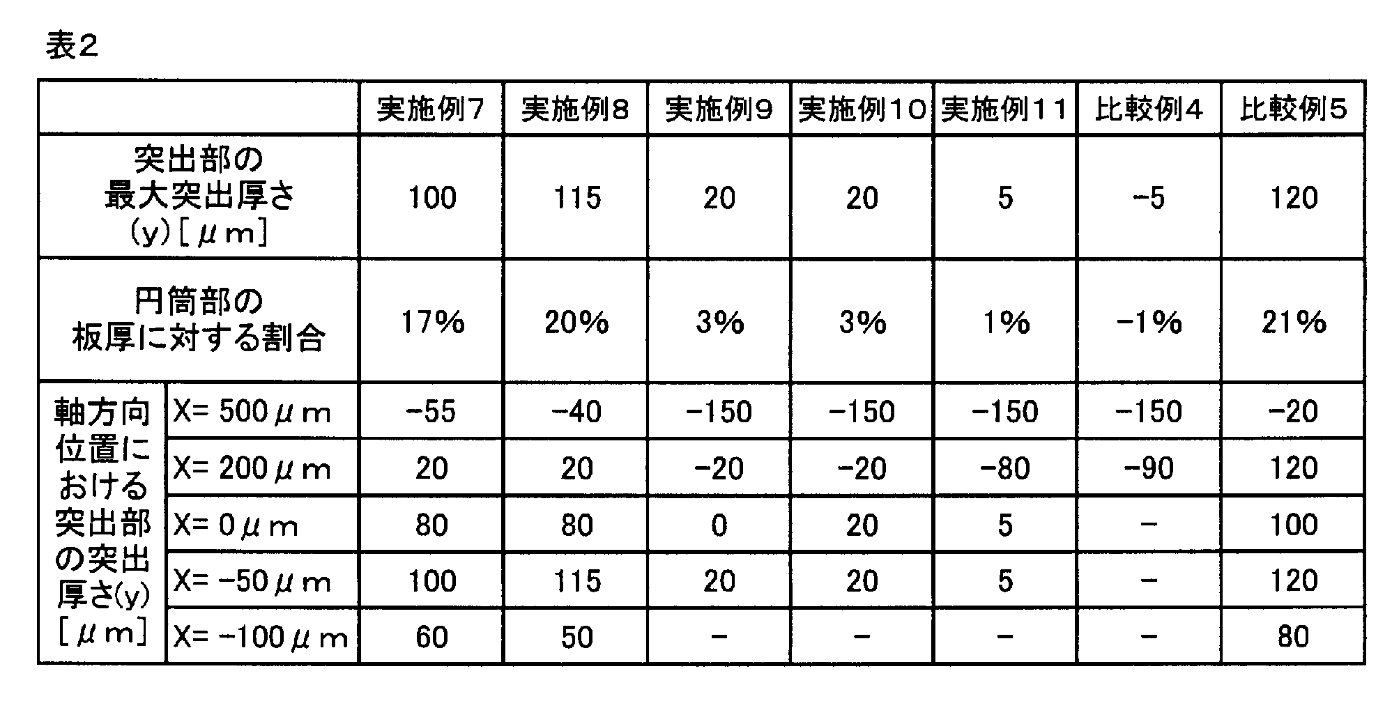

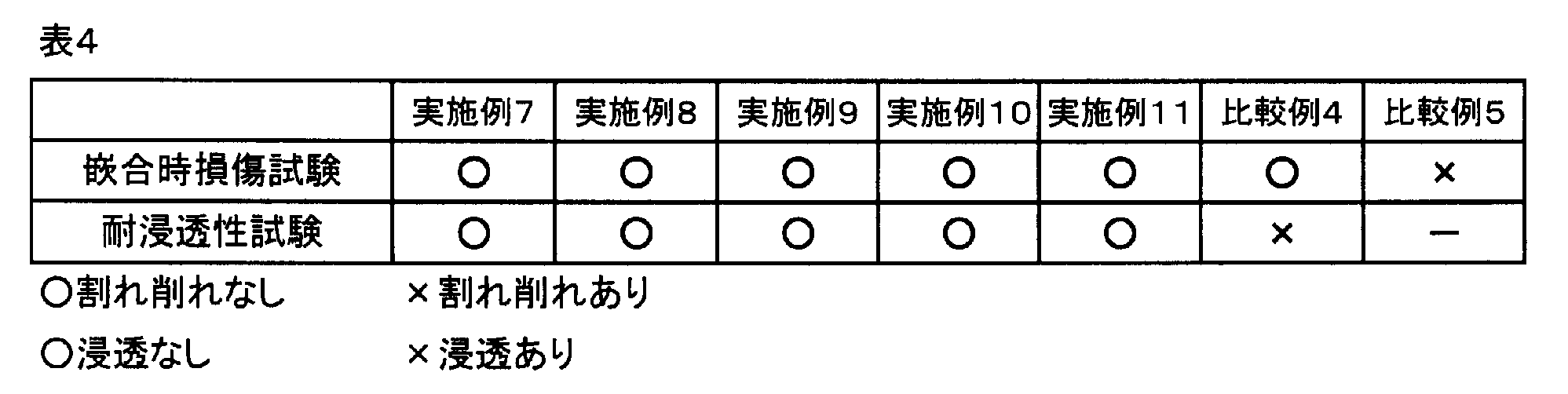


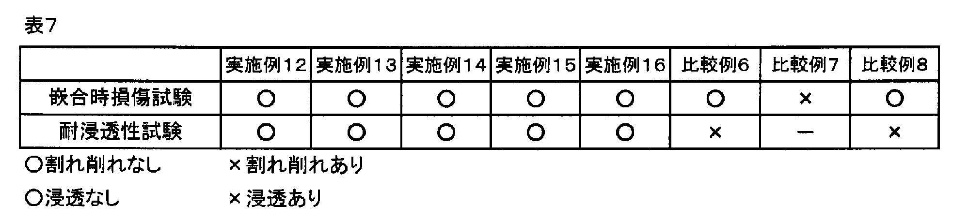

表3、表4、表7、及び表8から明らかなように、比較例1~10の磁気エンコーダでは、磁石部の割れや削れ及び浸透液の浸透が確認され、実施例1~20の磁気エンコーダでは、磁石部の割れや削れ及び浸透液の浸透が確認されなかった。従って、実施例1~20の結果は良好であり、本発明の有効性が実証された。
10 転がり軸受
11 内輪(回転部材)
11a 内輪軌道面
11b 外周面
12 外輪(固定部材)
12a 外輪軌道面
12b 内周面
13 転動体
14 シール部材
15 磁気エンコーダ
20 スリンガ
20a 円筒部
20b フランジ部
20c 直線部
20d R部
20e 内周面(嵌合面)、外周面(嵌合面)
21 磁石部
22,22A 突出部
A 直線部の範囲
B R部の範囲
C 円筒部の範囲
D 直線部とR部との境界線
11 内輪(回転部材)
11a 内輪軌道面
11b 外周面
12 外輪(固定部材)
12a 外輪軌道面
12b 内周面
13 転動体
14 シール部材
15 磁気エンコーダ
20 スリンガ
20a 円筒部
20b フランジ部
20c 直線部
20d R部
20e 内周面(嵌合面)、外周面(嵌合面)
21 磁石部
22,22A 突出部
A 直線部の範囲
B R部の範囲
C 円筒部の範囲
D 直線部とR部との境界線
Claims (2)
- 回転部材に嵌合可能な円筒部と、前記円筒部から径方向に延びるフランジ部と、を有するスリンガと、
前記スリンガの前記フランジ部の外側面に接着剤によって取り付けられ、円周方向に多極着磁された略円環状の磁石部と、を備える磁気エンコーダであって、
前記円筒部は、前記回転部材に嵌合される直線部と、前記直線部と前記フランジ部との境界部分であるR部と、を有し、
前記磁石部は、前記円筒部の嵌合面よりも径方向に突出する突出部を有し、
前記突出部は、前記円筒部の前記R部、又は、前記円筒部の前記直線部、又は、前記円筒部の前記R部から前記直線部に亘って形成され、
前記突出部の突出厚さは、前記円筒部の板厚の1~20%に設定され、
前記スリンガを前記回転部材に嵌合することにより、前記突出部が前記回転部材と前記スリンガの前記円筒部との間に挟み込まれて楔状に介在することを特徴とする磁気エンコーダ。 - 外周面に内輪軌道面を有する内輪と、内周面に外輪軌道面を有する外輪と、前記内輪軌道面と前記外輪軌道面との間に転動自在に配置される複数の転動体と、前記外輪の内周面及び前記内輪の外周面の一方に取り付けられ、軸受内部を密封するシール部材と、前記外輪の内周面及び前記内輪の外周面の他方に取り付けられる磁気エンコーダと、を備える転がり軸受であって、
前記磁気エンコーダが、請求項1に記載の磁気エンコーダであることを特徴とする転がり軸受。
Priority Applications (1)
| Application Number | Priority Date | Filing Date | Title |
|---|---|---|---|
| PCT/JP2015/063698 WO2016181515A1 (ja) | 2015-05-12 | 2015-05-12 | 磁気エンコーダ及び転がり軸受 |
Applications Claiming Priority (1)
| Application Number | Priority Date | Filing Date | Title |
|---|---|---|---|
| PCT/JP2015/063698 WO2016181515A1 (ja) | 2015-05-12 | 2015-05-12 | 磁気エンコーダ及び転がり軸受 |
Publications (1)
| Publication Number | Publication Date |
|---|---|
| WO2016181515A1 true WO2016181515A1 (ja) | 2016-11-17 |
Family
ID=57247988
Family Applications (1)
| Application Number | Title | Priority Date | Filing Date |
|---|---|---|---|
| PCT/JP2015/063698 Ceased WO2016181515A1 (ja) | 2015-05-12 | 2015-05-12 | 磁気エンコーダ及び転がり軸受 |
Country Status (1)
| Country | Link |
|---|---|
| WO (1) | WO2016181515A1 (ja) |
Cited By (1)
| Publication number | Priority date | Publication date | Assignee | Title |
|---|---|---|---|---|
| US12013038B2 (en) | 2020-06-12 | 2024-06-18 | Nok Corporation | Sealing device |
Citations (5)
| Publication number | Priority date | Publication date | Assignee | Title |
|---|---|---|---|---|
| JP2009127668A (ja) * | 2007-11-20 | 2009-06-11 | Koyo Sealing Techno Co Ltd | 密封装置 |
| JP2013061052A (ja) * | 2011-09-15 | 2013-04-04 | Nsk Ltd | エンコーダ付車輪支持用転がり軸受ユニット |
| JP2013079900A (ja) * | 2011-10-05 | 2013-05-02 | Nsk Ltd | エンコーダ及び組み合わせシールリング付ハブユニット |
| JP2013160303A (ja) * | 2012-02-06 | 2013-08-19 | Uchiyama Manufacturing Corp | 密封装置の嵌合方法及び密封装置 |
| WO2015056526A1 (ja) * | 2013-10-16 | 2015-04-23 | 日本精工株式会社 | エンコーダ付組み合わせシールリング及びエンコーダ付転がり軸受ユニット |
-
2015
- 2015-05-12 WO PCT/JP2015/063698 patent/WO2016181515A1/ja not_active Ceased
Patent Citations (5)
| Publication number | Priority date | Publication date | Assignee | Title |
|---|---|---|---|---|
| JP2009127668A (ja) * | 2007-11-20 | 2009-06-11 | Koyo Sealing Techno Co Ltd | 密封装置 |
| JP2013061052A (ja) * | 2011-09-15 | 2013-04-04 | Nsk Ltd | エンコーダ付車輪支持用転がり軸受ユニット |
| JP2013079900A (ja) * | 2011-10-05 | 2013-05-02 | Nsk Ltd | エンコーダ及び組み合わせシールリング付ハブユニット |
| JP2013160303A (ja) * | 2012-02-06 | 2013-08-19 | Uchiyama Manufacturing Corp | 密封装置の嵌合方法及び密封装置 |
| WO2015056526A1 (ja) * | 2013-10-16 | 2015-04-23 | 日本精工株式会社 | エンコーダ付組み合わせシールリング及びエンコーダ付転がり軸受ユニット |
Cited By (1)
| Publication number | Priority date | Publication date | Assignee | Title |
|---|---|---|---|---|
| US12013038B2 (en) | 2020-06-12 | 2024-06-18 | Nok Corporation | Sealing device |
Similar Documents
| Publication | Publication Date | Title |
|---|---|---|
| US10677291B2 (en) | Sealing device | |
| CN1302216C (zh) | 密封皮碗 | |
| CN105637245B (zh) | 带编码器的组合密封圈和带编码器的滚动轴承单元 | |
| CN107407420A (zh) | 密封装置 | |
| WO2011105366A1 (ja) | 自動二輪車用車輪の回転速度検出用エンコーダ付玉軸受およびこれを用いた自動二輪車用車輪の回転速度検出装置 | |
| JPWO2018110626A1 (ja) | 密封装置 | |
| US20120230622A1 (en) | Rolling bearing | |
| US9476735B2 (en) | Magnetic encoder and bearing device including magnetic encoder | |
| CN101688792B (zh) | 磁编码器和滚动轴承 | |
| CN110709632A (zh) | 密封装置 | |
| JP2004263738A (ja) | 密封装置 | |
| JP2008309717A (ja) | 磁気エンコーダ、及び該磁気エンコーダを備えた転がり軸受ユニット | |
| JP2015094706A (ja) | 磁気エンコーダ及び転がり軸受 | |
| JP2016023755A (ja) | 磁気エンコーダ及び転がり軸受 | |
| JP4889094B2 (ja) | トーンホイール | |
| EP2078935A1 (en) | Magnetized pulsar ring and rolling bearing unit with sensor equipped therewith | |
| CN1934379A (zh) | 带转动检测元件的密封装置 | |
| CN105247256A (zh) | 活塞密封组件 | |
| CN103256312B (zh) | 滚动轴承 | |
| EP2003424B1 (en) | Magnetic encoder and method for manufacturing the same | |
| JP2009002425A (ja) | 密封装置 | |
| CN102821989B (zh) | 一种密封系统的装置和方法 | |
| JP5267777B2 (ja) | 密封装置 | |
| KR20070027734A (ko) | 고리형상 부재 | |
| JP2007247708A (ja) | 軸付きシール |
Legal Events
| Date | Code | Title | Description |
|---|---|---|---|
| 121 | Ep: the epo has been informed by wipo that ep was designated in this application |
Ref document number: 15891839 Country of ref document: EP Kind code of ref document: A1 |
|
| NENP | Non-entry into the national phase |
Ref country code: DE |
|
| 122 | Ep: pct application non-entry in european phase |
Ref document number: 15891839 Country of ref document: EP Kind code of ref document: A1 |
|
| NENP | Non-entry into the national phase |
Ref country code: JP |