WO2016178408A1 - 繊維状ガラスの製造方法及び繊維状ガラスを備えた物品 - Google Patents
繊維状ガラスの製造方法及び繊維状ガラスを備えた物品 Download PDFInfo
- Publication number
- WO2016178408A1 WO2016178408A1 PCT/JP2016/063351 JP2016063351W WO2016178408A1 WO 2016178408 A1 WO2016178408 A1 WO 2016178408A1 JP 2016063351 W JP2016063351 W JP 2016063351W WO 2016178408 A1 WO2016178408 A1 WO 2016178408A1
- Authority
- WO
- WIPO (PCT)
- Prior art keywords
- glass
- fibrous
- fibrous glass
- manufacturing
- powder
- Prior art date
- Legal status (The legal status is an assumption and is not a legal conclusion. Google has not performed a legal analysis and makes no representation as to the accuracy of the status listed.)
- Ceased
Links
Images







Classifications
-
- C—CHEMISTRY; METALLURGY
- C03—GLASS; MINERAL OR SLAG WOOL
- C03B—MANUFACTURE, SHAPING, OR SUPPLEMENTARY PROCESSES
- C03B37/00—Manufacture or treatment of flakes, fibres, or filaments from softened glass, minerals, or slags
- C03B37/01—Manufacture of glass fibres or filaments
-
- D—TEXTILES; PAPER
- D01—NATURAL OR MAN-MADE THREADS OR FIBRES; SPINNING
- D01D—MECHANICAL METHODS OR APPARATUS IN THE MANUFACTURE OF ARTIFICIAL FILAMENTS, THREADS, FIBRES, BRISTLES OR RIBBONS
- D01D11/00—Other features of manufacture
-
- D—TEXTILES; PAPER
- D01—NATURAL OR MAN-MADE THREADS OR FIBRES; SPINNING
- D01D—MECHANICAL METHODS OR APPARATUS IN THE MANUFACTURE OF ARTIFICIAL FILAMENTS, THREADS, FIBRES, BRISTLES OR RIBBONS
- D01D5/00—Formation of filaments, threads, or the like
-
- D—TEXTILES; PAPER
- D01—NATURAL OR MAN-MADE THREADS OR FIBRES; SPINNING
- D01D—MECHANICAL METHODS OR APPARATUS IN THE MANUFACTURE OF ARTIFICIAL FILAMENTS, THREADS, FIBRES, BRISTLES OR RIBBONS
- D01D5/00—Formation of filaments, threads, or the like
- D01D5/08—Melt spinning methods
Definitions
- the present invention relates to a method for producing fibrous glass and an article provided with fibrous glass.
- fiber aggregates having an average fiber diameter of, for example, nanometer order have been used in various fields such as the field of regenerative medicine.
- an electrospinning method As a main manufacturing method of such fiber aggregates, an electrospinning method ( Hereinafter, the ES method is known (see, for example, Patent Document 1).
- the present invention has been made in order to solve the above-mentioned problems, and an object of the present invention is to provide a method for producing a fibrous glass and an article provided with the fibrous glass that can shorten the production time. There is to do.
- the manufacturing method of the fibrous glass which solves the said subject produces
- the fibrous glass is generated from the splashes of the non-fibrous glass melted and scattered at the irradiated portion of the energy rays. For this reason, for example, it is not necessary to carry out the sol-gel method implementation process as seen in the ES method, and the manufacturing time can be shortened and the fibrous glass can be manufactured easily and in large quantities.
- the fibrous glass on the collecting surface using electrostatic attraction and gravity, and the fibrous glass such as the suction mechanism and the winding mechanism can be positively collected. Even if it does not have a mechanism for collecting, the fibrous glass can be collected. Thereby, simplification of the manufacturing apparatus which manufactures fibrous glass is attained.
- the said energy beam is a laser beam. According to this manufacturing method, simplification is possible in a manufacturing apparatus for fibrous glass that generates fibrous glass by irradiating laser light.
- the collection surface is disposed on the opposite side of the non-fibrous glass to the side irradiated with the energy rays, and the fibrous glass generated on the opposite side is captured. It is preferable to collect at the collecting surface.
- the collecting surface is arranged on the side opposite to the side irradiated with the energy rays in the non-fibrous glass, and the fibrous glass generated on the opposite side is collected on the collecting surface. For this reason, it becomes possible to collect the fibrous glass without worrying about the interference between the generated fibrous glass and the energy ray, or the interference between the collecting surface for collecting the fibrous glass and the energy ray. .
- a sheet-like glass fiber aggregate is formed by depositing fibrous glass generated by irradiation of energy rays on non-fibrous glass on the collection surface. For this reason, it becomes possible to manufacture easily the sheet-like glass fiber aggregate which consists of fibrous glass.
- the non-fibrous glass is preferably plate glass. According to this manufacturing method, it becomes easy to secure a space on the side opposite to the side irradiated with the energy rays in the plate glass, which is suitable for collecting the fibrous glass on the side opposite to the plate glass.
- the average fiber diameter of the said fibrous glass is the range of 1 nm or more and 20 micrometers or less.
- a suitable fibrous glass can be produced in terms of biocompatibility and the like.
- An article provided with a fibrous glass that solves the above problems includes the fibrous glass produced by the method for producing a fibrous glass described above, and a support having the collection surface on which the fibrous glass is collected. It has.
- an article including the fibrous glass manufactured by the above-described manufacturing method of the fibrous glass has a configuration including a support having a collection surface used in the manufacturing process of the fibrous glass. For this reason, in the manufacturing process of the article
- an article provided with the fibrous glass is used as a cell culture substrate.
- the fibrous glass is suitable for use as a cell culture substrate for reasons such as excellent chemical durability as compared with a resin fiber, and the fibrous glass is A cell culture substrate supported by a support can be produced by a simplified production process.
- the manufacturing method of the fibrous glass which solves the said subject heats the said powder glass by irradiating the said powder glass by irradiating an energy beam to the powder glass mounted in the mounting part, and is fibrous.
- a glass fiber generation process for generating glass is provided.
- powder glass is heated by absorption of energy rays, and fibrous glass is generated from the sprayed powder that melts and scatters at the heated portion. For this reason, for example, it is not necessary to carry out the sol-gel method implementation process as seen in the ES method, and the manufacturing time can be shortened and the fibrous glass can be manufactured easily and in large quantities.
- powder glass is used as a glass material for generating fibrous glass by irradiation with energy rays.
- powdered glass tends to be melted by irradiation with energy rays, so that it is possible to shorten the time required for the production of fibrous glass.
- a glass material having a composition that is difficult to be previously formed into a plate shape or directly spun due to restrictions such as devitrification temperature can be easily formed into a fiber shape.
- the powder glass in the glass fiber generation step, is heated by the heat generated in the placement portion by irradiating the placement portion with the energy rays that have passed through the powder glass. It is preferable to do.
- the mounting portion is heated by irradiation with energy rays, and the powder glass is heated by the heat of the mounting portion.
- the temperature of the powdered glass is raised to a temperature at which the energy rays are easily absorbed by the heat from the mounting portion, and then absorbed by the energy rays.
- Powdered glass can be heated to produce fibrous glass. Therefore, according to this method, the types of powder glass that can be used can be expanded without being limited to the powder glass that can be used for producing the fibrous glass having the property of absorbing energy rays at room temperature.
- the fibrous glass can be provided without special heating means such as a heater for raising the temperature of the powder glass. Can be generated.
- the said manufacturing method of fibrous glass in the said glass fiber production
- the types of powder glass that can be used can be expanded without being limited to the powder glass that can be used for producing the fibrous glass having the property of absorbing energy rays at room temperature.
- the mounting portion since the mounting portion does not need to be capable of absorbing energy rays (that is, those that rise in temperature upon receiving energy rays), it can be a material that transmits energy rays, The types of materials that can be used for the mounting portion can be expanded.
- the manufacturing method of the fibrous glass which solves the said subject heats the said glass raw material by irradiating an energy beam to the glass raw material containing the silica sand mounted in the mounting part, and making the said glass raw material absorb the said energy beam. And a glass fiber generating step for generating fibrous glass.
- a glass material containing silica sand is heated by absorption of energy rays, and fibrous glass is generated from the splashes that are melted and scattered by the glass material in the heated portion. For this reason, for example, it is not necessary to carry out the sol-gel method implementation process as seen in the ES method, and the manufacturing time can be shortened and the fibrous glass can be manufactured easily and in large quantities. Furthermore, according to this method, a fibrous glass is not directly generated from a non-fibrous glass such as a plate glass or a powder glass generated from a glass raw material, but a fibrous glass is directly generated from the glass raw material. For this reason, the cost and effort which prepare non-fibrous glass can be saved, and it can contribute to the reduction of manufacturing cost.
- the energy source that has passed through the glass raw material is irradiated onto the mounting unit, and the glass raw material is heated by heat generated in the mounting unit. It is preferable to do.
- the mounting portion is heated by irradiation with energy rays, and the glass raw material is heated by the heat of the mounting portion.
- a glass raw material can be efficiently heated up to the temperature at which fibrous glass is produced.
- melted by irradiation of the said energy beam with respect to the said mounting part is made to adhere to the surface of the said fibrous glass, or the said It is preferable to mix in the inside of fibrous glass.
- the fibrous glass article in which the desired component was contained in fibrous glass can be obtained by selection of the constituent material of a mounting part.
- the mounting portion is made of a metal material
- a fibrous glass article made of a composite material of fibrous glass and metal can be obtained, and the article can be used for, for example, a catalyst.
- the said mounting part consists of metal materials. According to this manufacturing method, it becomes possible to produce a fibrous glass in which the metal material adheres or is mixed inside by melting the metal material constituting the mounting portion by irradiation with energy rays.
- generation process it is preferable to heat the said glass raw material by the heat source different from the said energy ray before or during irradiation of the said energy ray to the said glass raw material.
- the fibrous glass can be efficiently produced.
- the mounting portion does not need to be capable of absorbing energy rays (that is, those that rise in temperature upon receiving energy rays), it can be a material that transmits energy rays, The types of materials that can be used for the mounting portion can be expanded.
- the manufacturing method of the fibrous glass which solves the said subject is equipped with the glass fiber production
- generation process which produces
- generation process the said energy ray to the said plate glass Generation of the fibrous glass by irradiation is started from the end of the plate glass.
- this manufacturing method by irradiating the plate glass with energy rays, fibrous glass is generated from the splashes of the plate glass melted and scattered at the irradiated portion of the energy rays. For this reason, for example, it is not necessary to carry out the sol-gel method implementation process as seen in the ES method, and the manufacturing time can be shortened and the fibrous glass can be manufactured easily and in large quantities. Moreover, in this method, the production
- the average fiber diameter of the said fibrous glass is the range of 1 nm or more and 20 micrometers or less.
- a sufficient surface area can be provided.
- fibrous glass is used as a cell culture substrate (scaffold) in the field of regenerative medicine, it is possible to produce fibrous glass suitable for biocompatibility and the like.
- the fibrous glass manufacturing apparatus 10 for embodying the manufacturing method of the fibrous glass of this embodiment is demonstrated.
- the fibrous glass manufacturing apparatus 10 is an apparatus for manufacturing the fibrous glass Gf by irradiating the plate glass Gb (non-fibrous glass) with the laser light L.
- fine fibrous glass Gf having an average fiber diameter of about 1 nm to 20 ⁇ m, more preferably 10 nm to 1 ⁇ m is manufactured.
- the plate glass Gb used as the material of the fibrous glass Gf may be any material such as alkali-free glass, quartz glass, soda glass, borate glass, phosphate glass, aluminate glass, and the like. .
- the fibrous glass manufacturing apparatus 10 includes a stage S on which the plate glass Gb is placed, and a laser light irradiation unit 11 for irradiating the plate glass Gb with the laser light L.
- the laser beam irradiation part 11 is arrange
- the laser beam L radiate
- the surface (upper surface) of the plate glass Gb on which the laser light L is irradiated is the surface G1 of the plate glass Gb, and the opposite surface (lower surface) is the back surface G2 of the plate glass Gb.
- the laser beam irradiation unit 11 mainly includes a laser oscillator 12 (laser light source), a galvano scanner 13, an f ⁇ lens 14 (F-theta lens), and the like.
- the laser oscillator 12 is a device for oscillating the laser beam L and emitting it to the outside.
- any pulse width such as a femtosecond laser or a picosecond laser can be used as long as the glass sheet Gb can be locally heated to a temperature above the softening point.
- any wavelength such as a carbon dioxide laser or an excimer laser, may be used.
- the laser beam L oscillated by the laser oscillator 12 is then guided into the galvano scanner 13.
- the galvano scanner 13 is disposed in the laser beam irradiation unit 11 as an optical system for scanning the laser beam L irradiated to the plate glass Gb.
- the galvano scanner 13 includes a plurality (two in this embodiment) of galvanometer mirrors 15.
- Each galvanometer mirror 15 includes a drive motor 15a in which an encoder is incorporated, a mirror body 15b fixed to the tip of the output shaft of the drive motor 15a, and the like.
- the mirror body 15b is configured such that the plane portion is directed in a predetermined direction as the output shaft of the drive motor 15a rotates by a predetermined rotation direction and a rotation angle.
- the laser light L is emitted from the laser oscillator 12 to the galvano scanner 13
- the laser light L is introduced into the galvano scanner 13.
- the laser light L is bent by being reflected by each mirror body 15 b of the plurality of galvanometer mirrors 15 and led out to the outside of the galvanometer scanner 13.
- the predetermined program is preset, respectively, and operation
- movement of the drive motor 15a is controlled with high speed and high precision based on this program.
- the direction of the plane part of the mirror body 15b is flexibly changed, and the traveling direction of the laser light L after being derived from the galvano scanner 13 is freely changed.
- the laser beam L derived from the galvano scanner 13 is then guided to the f ⁇ lens 14.
- the f ⁇ lens 14 is a condensing lens, and converges the laser light L until it reaches a predetermined spot diameter to increase the energy density suitable for generating the fibrous glass Gf.
- the f ⁇ lens 14 of the present embodiment is provided with a plurality of lenses (not shown) arranged to face each other, and various laser beams that pass through the lens surface at the central part and the peripheral part of the lens surface.
- the scanning speed is always set to a constant value, and the laser beam L is designed to be always irradiated perpendicularly to the plate glass Gb.
- the laser light L that has passed through the f ⁇ lens 14 is irradiated perpendicularly to the surface G1 of the plate glass Gb with a predetermined spot diameter.
- the focal position of the laser light L at this time may be determined at an arbitrary position according to the focal depth of the laser light L, the characteristics of the plate glass Gb, and the like.
- the focal position of the laser beam L is set on the back surface G2 side (counterlight source side) of the plate glass Gb. It is preferable. Specifically, it is preferably located within the range of 0 mm to 10 mm with respect to the back surface G2 of the plate glass Gb. By setting to such a focal position, the glass sheet Gb can be efficiently heated to the back surface G2 side, so that the forming speed of the fibrous glass Gf can be increased.
- the focal position of the laser beam L is inside the plate glass Gb (the front surface G1, the back surface G2 of the plate glass Gb, and between them). It is preferable to be set to (including the above-mentioned region). By setting such a focal position, it is possible to suppress the diffusion of the energy of the laser light L and to suppress the molding failure of the fibrous glass Gf due to insufficient heating.
- the irradiation position of the laser light L irradiated to the plate glass Gb with respect to the plate glass Gb is changed (scanned) by the operation of the galvanometer mirror 15. At this time, the laser light L is applied to the plate glass Gb with a stable spot diameter by the action of the f ⁇ lens 14.
- the stage S has a collection surface 21 that forms a horizontal plane perpendicular to the vertical direction, and a plurality of (only two are shown in FIG. 1) pin-shaped support portions 22 that protrude upward from the collection surface 21 in the vertical direction. is doing.
- Each support portion 22 is configured to be able to horizontally support the plate glass Gb at its tip (upper end), and in a state where the plate glass Gb is supported by each support portion 22, the collection surface 21 is perpendicular to the back surface G 2 of the plate glass Gb. It is comprised so that it may oppose. That is, the collection surface 21 is positioned below the portion that supports the plate glass Gb (the tip of the support portion 22). Moreover, this collection surface 21 is comprised so that it may orthogonally cross with the optical axis La of the laser beam L radiate
- the stage S also serves as a collecting member for collecting the fibrous glass Gf generated by the irradiation of the laser light L with respect to the plate glass Gb.
- the stage S is preferably made of a metal that is resistant to the laser beam L.
- the area of the collecting surface 21, for example, is preferably set to 100mm 2 ⁇ 1000000mm about 2. Further, the distance from the back surface G2 of the plate glass Gb to the collection surface 21 is preferably set to, for example, about 0.1 mm to 200 mm (more preferably 0.5 mm to 100 mm). If it is in such a size range, fibrous glass Gf can be efficiently collected by the collection surface 21.
- the said dimension range is an example, and you may determine the area from the collection surface 21 and the distance from the back surface G2 of the plate glass Gb to the collection surface 21 arbitrarily.
- the laser light irradiation unit 11 is operated to irradiate the plate glass Gb with the laser light L.
- the laser beam irradiation unit 11 first, the laser beam L is oscillated from the laser oscillator 12, and the oscillated laser beam L sequentially passes through the galvano scanner 13 and the f ⁇ lens 14, and then the surface G1 of the plate glass Gb. Irradiated with a predetermined spot diameter.
- the operation of the galvanometer mirror 15 is controlled based on a predetermined program set in advance, and the irradiation position of the laser light L on the plate glass Gb is scanned.
- the glass sheet Gb is heated by the irradiation of the laser beam L, whereby the fibrous glass Gf is generated on the back surface G2 side of the portion irradiated with the laser beam L.
- a method for producing the fibrous glass Gf a known technique described in, for example, Japanese Patent Application Laid-Open No. 2015-61809 can be used.
- the fibrous glass Gf generated on the back surface G2 of the plate glass Gb by the irradiation of the laser light L is collected on the collection surface 21 of the stage S by its own weight and the kinetic energy induced by the laser light L. Further, the fibrous glass Gf may be subjected to electrostatic attraction between the collecting surface 21 and the fibrous glass Gf is also collected on the collecting surface 21 by the electrostatic attraction. It is like that. Then, by depositing a predetermined amount of the fibrous glass Gf on the collecting surface 21, a sheet-like glass fiber aggregate Gs is generated on the collecting surface 21. At this time, the sheet shape of the glass fiber aggregate Gs is maintained by, for example, entanglement or partial welding of a large number of fibrous glasses Gf falling on the collection surface 21. .
- the glass fiber aggregate Gs formed into a sheet shape can be arbitrarily peeled from the collecting surface 21 using a peeling tool such as tweezers or a squeegee. Moreover, if a net-like member is previously arranged on the collection surface 21, the glass fiber aggregate Gs can be easily peeled off from the collection surface 21 without losing its shape by removing the net-like member. .
- the average of the glass fiber aggregate Gs is preferably 1 nm to 20 ⁇ m, more preferably 10 nm to 1 ⁇ m.
- the use of the glass fiber aggregate Gs is not limited thereto, and can be used as, for example, a wound dressing material, a mechanical vibrator, an optical component, a catalyst, and the like.
- the fibrous glass Gf generated on the back surface G2 side of the plate glass Gb is dropped by the kinetic energy induced by the own weight of the fibrous glass Gf and the laser light L.
- the light is collected on the collecting surface 21 of the stage S.
- a mechanism for positively collecting the fibrous glass Gf such as an intake mechanism for sucking and collecting the generated fibrous glass Gf together with air and a winding mechanism for winding and collecting the fibrous glass Gf. Even if it is not provided, the fibrous glass Gf can be collected, and as a result, the fibrous glass manufacturing apparatus 10 can have a simple configuration.
- the sheet-like glass fiber aggregate Gs is formed by depositing a predetermined amount of the fibrous glass Gf on the collection surface 21.
- the fibrous glass Gf can be collected only in a state other than the sheet form. Therefore, in order to obtain the sheet-like glass fiber aggregate Gs, the collection is performed.
- molds many fibrous glass Gf which carried out to a sheet form is needed.
- the sheet-like glass fiber aggregate Gs can be formed simply by collecting (depositing) the fibrous glass Gf falling from the plate glass Gb on the collecting surface 21.
- a special process for forming the glass Gf into a sheet is not necessary, and as a result, it can contribute to simplification of the manufacturing process.
- Fibrous glass Gf is generated on the back surface G2 side of the plate glass Gb by irradiation of the laser beam L from the front surface G1 side to the plate glass Gb. Therefore, the fiber glass Gf can be captured without worrying about interference between the generated fiber glass Gf and the laser light L, or interference between the member for collecting the fiber glass Gf and the laser light L. Collection is possible.
- the plate glass Gb Since the material for generating the fibrous glass Gf is the plate glass Gb, the plate glass Gb can be stably supported in a state of being separated upward from the collection surface 21. Thereby, it becomes easy to secure a space on the back surface G2 side (counter irradiation side) of the plate glass Gb, and the fibrous glass Gf is collected on the back surface G2 side (counter irradiation side) of the plate glass Gb as in this embodiment. It is suitable for the case.
- the manufactured fiber glass Gf is used for cell culture in the field of regenerative medicine, for example.
- the fibrous glass Gf is suitable for use as a cell culture substrate for reasons such as excellent chemical durability as compared with a fiber product made of resin.
- the fibrous glass Gf generated on the back surface G2 of the plate glass Gb by the irradiation with the laser light L is dropped by its own weight and the kinetic energy induced by the laser light L, and is collected on the collecting surface 21.
- the collection method of fibrous glass Gf is not specifically limited to this, It can change suitably.
- the fibrous glass Gf may be collected by a collecting member 31 arranged on the stage S.
- the collection member 31 has a collection surface 31a along the optical axis La of the laser light L irradiated to the plate glass Gb.
- generated to the back surface G2 side of this plate glass Gb by irradiation of the laser beam L with respect to plate glass Gb comes to be collected (combined) by the collection surface 31a by electrostatic attraction. Yes.
- the fibrous glass Gf can be collected without providing a mechanism for actively collecting the fibrous glass Gf such as the intake mechanism and the winding mechanism described above.
- the glass glass manufacturing apparatus 10 can have a simple configuration.
- the produced fibrous glass Gf as a glass article (for example, a cell culture substrate) including the collecting member 31. That is, in this example, it is possible to manufacture a glass article provided with the collection member 31 as a support for the fibrous glass Gf.
- a support for supporting the fibrous glass Gf is prepared separately from the collecting member 31, and the step of transferring the fibrous glass Gf taken out from the collecting member 31 to the supporting member is omitted. Can contribute to simplification of the manufacturing process.
- the collection member 31 is fixed to the back surface G2 of the plate glass Gb in advance, and the fibrous glass Gf generated on the back surface G2 side of the plate glass Gb by irradiation of the laser light L to the plate glass Gb. Is collected at the collection surface 31 a of the collection member 31.
- a glass article configured by combining the fibrous glass Gf with each of the plate glass Gb and the collecting member 31 is manufactured. be able to.
- FIG. 4 a collecting member 32 having a collecting surface 32a that intersects (orthogonally in FIG. 4) the optical axis La of the laser light L applied to the plate glass Gb may be used.
- the collection member 32 is placed on the stage S, and the fibrous glass Gf generated on the back surface G2 side of the plate glass Gb by irradiating the plate glass Gb with the laser light L is the fiber glass.
- the fibrous glass Gf is combined with each of the plate glass Gb and the collecting member 32 by keeping the fibrous glass Gf bonded to the back surface G2 of the plate glass Gb. It is possible to manufacture a glass article. In addition, it is good also as a structure by which the fibrous glass Gf was cut
- the glass sheet Gb is irradiated with the laser light L, and the fibrous glass Gf is generated on the side opposite to the sheet glass Gb (the back surface G2 side).
- the fibrous glass Gf may be generated on the irradiation side of the laser light L.
- a light-collecting collection member 33 made of, for example, plate glass intersects the optical axis La of the laser light L on the irradiation surface side (surface G1 side) of the plate glass Gb (see FIG. 5). 5 are orthogonal).
- the collection member 33 has a collection surface 33a that faces the surface G1 of the plate glass Gb in the vertical direction.
- the laser beam L emitted from the laser beam irradiation unit 11 passes through the collection member 33 and is irradiated onto the surface G1 of the plate glass Gb.
- generated by the surface G1 side of the plate glass Gb by irradiation of the laser beam L comes to be collected (combined) by the collection surface 33a of the collection member 33 by electrostatic attraction. ing.
- the fibrous glass Gf can be collected without providing a mechanism for actively collecting the fibrous glass Gf such as the intake mechanism and the winding mechanism described above.
- the glass glass manufacturing apparatus 10 can have a simple configuration.
- the fiber glass Gf is generated by irradiating the horizontally arranged plate glass Gb with the laser light L from above. It is not specifically limited to. For example, you may comprise so that the laser beam L may be irradiated from the downward direction with respect to the glass plate Gb arrange
- the plate glass Gb is used as a material (non-fibrous glass) for generating the fibrous glass Gf.
- the present invention is not particularly limited thereto, and a tube glass may be used as the material.
- a glass raw material containing amorphous powder glass (glass fine particles) Gp or crystalline silica sand may be used as a material for generating the fibrous glass Gf.
- a predetermined amount of powdered glass Gp is disposed on the stage S, and the collecting member 34 is disposed on the irradiation side (above) of the powdered glass Gp.
- This collection member 34 has a collection surface 34a along the optical axis La of the laser light L irradiated to the powder glass Gp.
- the fiber glass Gf When the laser light L is irradiated on the powder glass Gp from above, the fiber glass Gf is generated from the powder glass Gp on the upper side (laser light irradiation unit 11 side), and the fiber glass Gf is electrostatically charged. It is collected (coupled) to the collecting surface 34a by a specific attractive force.
- the collection surface 21 was comprised so as to be orthogonal to the optical axis La of the laser beam L, it is not restricted to these, but the collection surface 21 cross
- the fibrous glass Gf is generated from the plate glass Gb (non-fibrous glass) by the irradiation with the laser light L.
- the plate glass Gb (non-fibrous) is irradiated by irradiating an electron beam.
- Fiber glass Gf may be generated from glass.
- a voltage may be applied to the collecting member so as to positively generate an electrostatic attractive force on each collecting surface.
- the fibrous glass Gf and the attached matter of the fibrous glass Gf have magnetism, if the magnetic force is generated in the collecting member, the fibrous glass Gf is attracted by the magnetic attractive force with respect to the collecting member. The glass Gf can be easily collected.
- the space in which the fibrous glass Gf is generated (for example, the space X (see FIGS. 1 to 5) between the plate glass Gb and the stage S) is a closed space.
- the space X can be easily defined as a closed space. can do. According to such a configuration, it is difficult for airflow to occur in the space X. Therefore, it becomes difficult for the fibrous glass Gf to be blown off by the air flow, and the fibrous glass Gf can be collected more reliably.
- the glass fiber aggregate Gs can be easily formed with a uniform thickness.
- the collection surface 21 of the stage S is parallel to the plate glass Gb, and in the example shown in FIGS. 2 and 3, the collection surface 31a of the collection member 31 is the plate glass Gb.
- the present invention is not limited to this, and the collection surface of the collection member may be inclined with respect to the plate glass Gb.
- the fibrous glass Gf can be suitably collected by the collecting member by swinging the collecting member. Note that such a swinging of the collecting member is particularly effective when the average fiber diameter is relatively large.
- the glass fiber Gf is produced
- the fibrous glass Gf may be generated by irradiating the laser beam L.
- the plate glass Gb does not have to be flat and may have a curved shape.
- the fibrous glass manufacturing apparatus 10 for embodying the manufacturing method of the fibrous glass of this embodiment is demonstrated.
- the fibrous glass manufacturing apparatus 10 is an apparatus for manufacturing the fibrous glass Gf (see FIG. 9) by irradiating an amorphous powder glass Gp with laser light L.
- fine fibrous glass Gf having an average fiber diameter of about 1 nm to 20 ⁇ m, more preferably 10 nm to 1 ⁇ m is manufactured.
- the powder glass Gp used as the raw material of the fibrous glass Gf is a powder glass made of a large number of silica fine particles (fumed silica) having an average particle diameter of about 10 nm.
- the fibrous glass manufacturing apparatus 10 includes a stage S (mounting unit) on which the powder glass Gp is mounted, and a laser beam irradiation unit 11 for irradiating the powder glass Gp with the laser beam L.
- the laser light irradiation unit 11 is disposed above the powder glass Gp placed on the placement surface Sa of the stage S, and the laser light L from the laser light irradiation unit 11 is irradiated onto the powder glass Gp from above. It has come to be.
- the stage S is made of a material that absorbs a laser beam L having a wavelength described later.
- the stage S is made of a metal material such as stainless steel.
- the mounting surface Sa is formed in a planar shape perpendicular to the vertical direction. That is, the mounting surface Sa is perpendicular to the optical axis La of the laser light L emitted along the vertical direction.
- the laser beam irradiation unit 11 mainly includes a laser oscillator 12 (laser light source), a galvano scanner 13, an f ⁇ lens 14 (F-theta lens), and the like.
- the laser oscillator 12 is a device for oscillating the laser light L and emitting it to the outside.
- a continuous wave fiber laser that generates the laser light L having a wavelength of about 1070 nm is used for the laser oscillator 12.
- the oscillation method of the laser oscillator 12 is not limited to continuous oscillation, but may be pulse oscillation.
- the laser beam L oscillated by the laser oscillator 12 is then guided into the galvano scanner 13.
- the galvano scanner 13 is disposed in the laser beam irradiation unit 11 as an optical system for scanning the laser beam L irradiated to the powder glass Gp.
- the galvano scanner 13 includes a plurality (two in this embodiment) of galvanometer mirrors 15.
- Each galvanometer mirror 15 includes a drive motor 15a in which an encoder is incorporated, a mirror body 15b fixed to the tip of the output shaft of the drive motor 15a, and the like.
- the mirror body 15b is configured such that the plane portion is directed in a predetermined direction as the output shaft of the drive motor 15a rotates by a predetermined rotation direction and a rotation angle.
- the laser light L is emitted from the laser oscillator 12 to the galvano scanner 13
- the laser light L is introduced into the galvano scanner 13.
- the laser light L is bent by being reflected by each mirror body 15 b of the plurality of galvanometer mirrors 15 and led out to the outside of the galvanometer scanner 13.
- the predetermined program is preset, respectively, and operation
- movement of the drive motor 15a is controlled with high speed and high precision based on this program.
- the direction of the plane part of the mirror body 15b is flexibly changed, and the traveling direction of the laser light L after being derived from the galvano scanner 13 is freely changed.
- the laser beam L derived from the galvano scanner 13 is then guided to the f ⁇ lens 14.
- the f ⁇ lens 14 is a condensing lens, and converges the laser light L until it reaches a predetermined spot diameter to increase the energy density suitable for generating the fibrous glass Gf.
- the f ⁇ lens 14 of the present embodiment is provided with a plurality of lenses (not shown) arranged to face each other, and various laser beams that pass through the lens surface at the central part and the peripheral part of the lens surface.
- the scanning speed is always set to a constant value, and the laser beam L is designed to always irradiate the mounting surface Sa of the stage S perpendicularly.
- the focal position of the laser light L emitted toward the powder glass Gp is set on the mounting surface Sa of the stage S.
- the irradiation position of the laser light L with respect to the powder glass Gp is changed (scanned) by the operation of the galvanometer mirror 15.
- the laser light L is applied to the powder glass Gp with a stable spot diameter by the action of the f ⁇ lens 14.
- the laser light irradiation unit 11 is operated to irradiate the powder glass Gp with the laser light L.
- the laser beam L is oscillated from the laser oscillator 12, and the oscillated laser beam L sequentially passes through the galvano scanner 13 and the f ⁇ lens 14, and then proceeds to the powder glass Gp.
- the laser beam L is oscillated from the laser oscillator 12, and the oscillated laser beam L sequentially passes through the galvano scanner 13 and the f ⁇ lens 14, and then proceeds to the powder glass Gp.
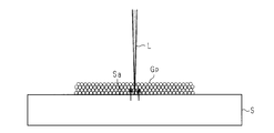
- the powder glass Gp (fumed silica) has a very high transmittance at room temperature with respect to the laser light L having the above wavelength (that is, an absorption coefficient is extremely small). For this reason, when the atmospheric temperature in the fibrous glass manufacturing apparatus 10 is normal temperature, the laser light L emitted from the laser light irradiation unit 11 is transmitted through the powder glass Gp with almost no absorption, and the stage S The mounting surface Sa is irradiated.
- the stage S is made of a metal material having a large absorption coefficient with respect to the laser light L having the above wavelength, the portion receiving the laser light L on the mounting surface Sa of the stage S absorbs the laser light L and is heated.
- the heat of the mounting surface Sa heated (heated) by the laser light L is transmitted to the powder glass Gp, and the powder glass Gp is heated. Since the powder glass Gp has a characteristic that the transmittance of the laser beam L decreases (the absorption coefficient increases) when the temperature reaches a predetermined temperature, the powder glass Gp is heated by absorbing the laser beam L when reaching the predetermined temperature. The When the temperature of the powder glass Gp becomes equal to or higher than the softening point, as shown in FIG. 9, the powder glass Gp is melted and scattered around, and the scattered molten glass is cooled and solidified while maintaining the fiber shape. A glassy glass Gf is produced.
- part of the laser beam L is deposited on the collection member (illustration omitted) mounted in the stage S.
- a method is conceivable.
- Fiber glass Gf By the above production method, an aggregate of fine fibrous glass Gf having an average fiber diameter of 1 nm or more and 20 ⁇ m or less, more preferably 10 nm or more and 1 ⁇ m or less is generated.
- the constituent elements of the aggregate of the produced fibrous glass Gf were analyzed by an electron beam microanalyzer (EPMA), and the analysis result by EPMA is shown in FIG. From the figure, it can be seen that the aggregate of the fibrous glass Gf contains Fe derived from the stage S as a constituent element in addition to silica which is a component of the powder glass Gp. That is, according to the manufacturing method of this embodiment, the composite material of fibrous glass Gf and a metal can be produced
- EPMA electron beam microanalyzer
- the composite material of the fibrous glass Gf and the metal can be used for, for example, a catalyst, and in this case, the fibrous glass Gf functions as a carrier for supporting a metal component as a catalyst.
- carrier can be given because the average fiber diameter of fibrous glass Gf shall be about 1 nm or more and about 20 micrometers or less as mentioned above.
- powder glass Gp is used as a glass material for irradiating laser beam L to generate fibrous glass Gf.
- the powder glass Gp tends to be melted by the irradiation of the laser light L, so that the time required for generating the fibrous glass Gf can be shortened.
- a glass material having a composition that is difficult to be previously formed into a plate shape or directly spun due to restrictions such as devitrification temperature can be easily formed into a fiber shape.
- the powder glass Gp is heated by the heat generated on the mounting surface Sa by irradiating the mounting surface Sa of the stage S with the laser light L transmitted through the powder glass Gp.
- the mounting surface Sa is heated by the irradiation of the laser beam L
- the powder glass Gp is heated by the heat of the mounting surface Sa.
- the powder glass Gp that can be used for the production of the fibrous glass Gf is not limited to those having the characteristic of absorbing the laser light L at room temperature, and the types of powder glass Gp that can be used are expanded. be able to. Moreover, in this method, since irradiation of the laser beam L to the powder glass Gp also serves to heat the mounting surface Sa, it is not necessary to provide a special heating means such as a heater for heating the powder glass Gp. Also, it becomes possible to produce the fibrous glass Gf.
- the constituent components of the stage S (mounting surface Sa) melted by the irradiation of the laser light L with respect to the stage S are attached to the surface of the fibrous glass Gf, or the fibrous glass Gf Mix inside.
- the fibrous glass article (aggregate of fibrous glass Gf) comprised including the component of the stage S (mounting surface Sa) can be manufactured.
- the fibrous glass article in which the desired component was contained in fibrous glass Gf can be obtained by selection of the constituent material of stage S (mounting surface Sa).
- the mounting surface Sa of the stage S is made of a metal material as in this embodiment, a fibrous glass article made of a composite material of the fibrous glass Gf and the metal can be obtained. It can be used for
- stage S (mounting surface Sa) is made of a metal material
- the metal material constituting the stage S is melted by irradiation with the laser light L, and the metal material is attached to or inside the fibrous glass Gf. It can be mixed.
- the average fiber diameter of the produced fibrous glass Gf is in the range of 1 nm or more and 20 ⁇ m or less, when the produced fibrous glass Gf is used for, for example, a catalyst application (support), a sufficient surface area is provided. You can have it.
- a fibrous glass Gf suitable for biocompatibility and the like can be produced.
- the mounting surface Sa is heated by irradiating the mounting surface Sa of the stage S with the laser beam L which permeate
- the mounting surface Sa The temperature at which the powder glass Gp is likely to absorb the laser beam L due to the heat generated in step S1.
- the means for raising the temperature of the powder glass Gp to a temperature at which the laser light L is easily absorbed is not limited to the second embodiment, and what is the laser light L for raising the temperature of the powder glass Gp? Another heat source may be provided.
- a heater H is provided as a heat source different from the laser beam L below the stage S (on the side opposite to the mounting surface Sa).
- the powder glass Gp is heated via the stage S by the heater H before the laser light L is irradiated onto the powder glass Gp.
- the fiber glass Gf is produced
- the powder glass Gp that can be used for the production of the fibrous glass Gf is not limited to those having the property of absorbing the laser light L at room temperature, and the types of powder glass Gp that can be used are expanded. be able to.
- the stage S (mounting surface Sa) does not need to be heated by irradiation with the laser beam L, and therefore, the laser beam L having the above wavelength (approximately 1070 nm) is used as a constituent material of the stage S. It is possible to use a material to be transmitted (a material having a small absorption coefficient).
- transmits the laser beam L of the said wavelength quartz glass, sapphire glass, etc. are mentioned, for example.
- the stage S (mounting surface Sa) is made of such a material that transmits the laser light L
- the mounting surface Sa does not absorb the laser light L
- the components of the mounting surface Sa are melted. Since it does not occur, it is possible to obtain a fibrous glass Gf that does not contain the components of the stage S.
- the heater H is provided in the configuration in which the stage S is made of a metal material as in the second embodiment, the stage S is heated by the heater H in addition to the heating of the stage S by irradiation with the laser light L.
- the time required for the powder glass Gp to be equal to or higher than the temperature at which the laser light L is easily absorbed can be shortened, and as a result, the manufacturing time can be further shortened.
- the powder glass Gp is heated by the heater H before the laser light L is irradiated to the powder glass Gp.
- the laser light L is irradiated to the powder glass Gp.
- the powder glass Gp may be heated by the heater H inside.
- the powder glass Gp is heated indirectly, but it is not restricted to this,
- the powder glass Gp may be heated by disposing the heater H above the stage S and raising the ambient temperature around the powder glass Gp with the heater H.
- the powder glass Gp can easily absorb the laser light L. You may heat more than this temperature.
- the constituent components of the stage S are included in the fibrous glass Gf according to the use of the fibrous glass Gf (that is, whether or not the constituent material of the stage S is a material that absorbs the laser light L).
- the fiber glass Gf according to a use can be obtained also by selecting.
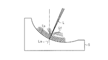
- the mounting surface Sa of the stage S is formed in a planar shape that is perpendicular to the vertical direction, but may be inclined with respect to the vertical direction, for example. Thereby, the scattering direction of the fibrous glass Gf can be promoted in the inclination direction of the placement surface Sa. Further, as shown in FIG. 13, the mounting surface Sa may be inclined with respect to the vertical direction and formed in a curved surface.
- the laser beam L is emitted so that the optical axis La is along the vertical direction.
- the optical axis La may be inclined with respect to the vertical direction.
- the optical axis La of the laser beam L is tilted corresponding to the tilt direction of the mounting surface Sa.
- the laser beam L is emitted upward from the lower side (opposite the mounting surface Sa) of the stage S made of a material that transmits the laser beam L, and is transmitted through the stage S.
- the laser beam L to be irradiated may be applied to the powder glass Gp on the mounting surface Sa.
- the metal powder is mixed with the powder glass Gp, and the powder obtained by mixing the powder glass Gp and the metal powder is irradiated with the laser light L, so that the composite of the fibrous glass Gf and the metal Material may be produced.
- the powder glass Gp made of silica fine particles is used, but the glass used for the powder glass Gp is, for example, alkali-free glass, soda glass, borate glass, phosphorus Any material such as an acid glass or an aluminate glass may be used. Moreover, the average particle diameter of powder glass Gp is not limited to the said 2nd Embodiment, It can change suitably.
- Powdered glass may be produced by any conventionally known method. For example, powdered glass can be obtained by forming molten glass into a film shape, water-pulverizing it, and then powdering it using a ball mill or the like.
- the wavelength of the laser beam L irradiated to the powder glass Gp is not limited to the second embodiment, and if the powder glass Gp can be locally heated to a temperature equal to or higher than the softening point, The wavelength of the laser beam L can be changed.
- the powder glass Gp is irradiated with the laser light L to generate the fibrous glass Gf.
- the powder glass Gp is irradiated with an electron beam to generate the fibrous glass Gf. May be.
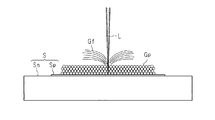
- the mounting surface on which the powder glass Gp in the stage S is mounted may be configured by a mounting member Sp that is a separate member from the stage main body Sm.
- the stage S includes a stage main body Sm and a mounting member Sp provided on the stage main body Sm.
- the mounting member Sp is made of a metal foil such as stainless steel that absorbs the laser light L.
- the fibrous glass Gf is generated by irradiating the powder glass Gp placed on the placing member Sp of the stage S with the laser light L.
- the constituent component of the mounting member Sp melted by the irradiation of the laser beam L to the mounting member Sp can be attached to the surface of the fibrous glass Gf (or mixed into the fibrous glass Gf).
- the fibrous glass article (aggregate of fibrous glass Gf) comprised including the structural component of the mounting member Sp can be manufactured.
- the mounting member Sp is made of a metal material
- a fibrous glass article made of a composite material of the fibrous glass Gf and the metal can be obtained, and the article can be used for, for example, a catalyst. .
- the stage member Sm is simply made of a metal material in the stage S, and the stage main body Sm is made of a material other than metal. It becomes possible to comprise with material (for example, glass etc.). Further, in the stage S, the part on which the powder glass Gp is placed is melted by the irradiation of the laser beam L. Therefore, this part is constituted by the placing member Sp that is separate from the stage main body Sm. When it deteriorates, it can respond by exchanging the mounting member Sp, and the maintainability can be improved.
- the mounting member Sp may be configured by a single metal foil, or may be configured by stacking a plurality of metal foils. Moreover, it is good also as a structure which mounted metal foil on the plate-shaped member which consists of glass and a metal as mounting member Sp.
- FIG. 15 illustrates an example in which the fibrous glass Gf is generated from the powder glass Gp.
- the present invention is not limited thereto, and for example, as illustrated in FIG. 16, the plate glass Gb is placed on the placement member Sp.
- the fibrous glass Gf may be generated by irradiating the plate glass Gb with the laser light L.
- generation of the fibrous glass Gf by irradiation of the laser beam L to the plate glass Gb is started from the edge part Gb1 (edge) of the said plate glass Gb.
- the stage S is configured to include the mounting member Sp, but is not particularly limited thereto, and the configuration of the stage S can be changed as appropriate.
- the present embodiment differs from the second embodiment only in that the glass raw material M is used as a material for generating the fibrous glass Gf, and the second embodiment is used as the fibrous glass manufacturing apparatus. Since it is the same structure as the thing of the thing, the detailed description is abbreviate
- the glass raw material M for producing the fibrous glass Gf is a known raw material containing crystalline silica sand (SiO 2 ).
- the average particle diameter of the glass raw material M is preferably 300 ⁇ m or less, more preferably 200 ⁇ m or less, and still more preferably 100 ⁇ m or less.
- the glass raw material M placed on the placement surface Sa of the stage S is irradiated with the laser light L. Then, the glass material M is heated by the irradiation of the laser beam L and the heat of the mounting surface Sa heated (heated) by the laser beam L.
- the temperature of the glass raw material M becomes equal to or higher than the softening point, the glass raw material M melts and scatters to the surroundings, and the scattered molten glass is cooled and solidified while maintaining a fiber shape, thereby generating a fibrous glass Gf. .
- a collecting member (not shown) in which the fibrous glass Gf scattered around from the irradiated portion of the laser light L is placed on the stage S is used.
- a method of depositing on the surface is conceivable.
- an aggregate of fine fibrous glass Gf having an average fiber diameter of about 1 nm to 20 ⁇ m, more preferably 10 nm to 1 ⁇ m is generated.
- Si contained 55 to 60%
- O contained 33 to 35%
- Fe and Ni contained 3 to 10% in total.
- the constituent elements of the produced fibrous glass Gf include Fe and Ni derived from the stage S in addition to Si and O, which are components of the glass raw material M (mainly silica sand).
- the composite material of fibrous glass Gf and a metal can be produced
- assembly of fibrous glass Gf adheres to the surface of fibrous glass Gf, or is mixed in fibrous glass Gf.
- the composite material of the fibrous glass Gf and metal produced by the method of the present embodiment can be used for, for example, a catalyst as in the above embodiments.
- the following effects can be obtained.
- a process is provided. In this step, the glass raw material M is heated by absorption of the laser light L, and the fibrous glass Gf is generated from the splashes obtained by melting and scattering the glass raw material M at the heated portion. For this reason, it is not necessary to carry out the sol-gel method implementation process as seen in, for example, the ES method, and the manufacturing time can be shortened and the fibrous glass Gf can be manufactured easily and in large quantities. Furthermore, according to this method, since the fibrous glass Gf is generated directly from the glass raw material M, the cost and labor for preparing non-fibrous glass can be saved, and the manufacturing cost can be reduced.
- the glass raw material M is heated by the heat generated on the mounting surface Sa.
- the mounting surface Sa is heated by the irradiation of the laser beam L, and the glass raw material M is heated by the heat of the mounting surface Sa.
- the glass raw material M can be efficiently heated up to the temperature at which the fibrous glass Gf is generated.
- the glass material M may be heated by a heat source (heater H) different from the laser light L before or during the irradiation of the laser light L to the glass material M (FIG. 11). And the heater H shown in FIG. 12). According to this, since the glass raw material M is heated by the heat source up to a temperature at which the fibrous glass Gf is generated, the fibrous glass Gf can be efficiently generated.
- the stage S since the stage S does not have to be capable of absorbing the laser light L (that is, the temperature rising upon receiving the laser light L), a material that transmits the laser light L (for example, quartz glass). Or sapphire glass), and the types of materials that can be used for the stage S can be expanded.
- a material that transmits the laser light L for example, quartz glass. Or sapphire glass
- the cross-sectional shape of the fibrous glass Gf generated in each of the above embodiments and modifications may be a circular shape, an elliptical shape, a rectangular shape, other flat shapes, or a shape formed by a combination thereof. Further, one fibrous glass Gf may be generated at the time of generation, or two or more may be generated at the same time.
- bonded with both a support body and non-fibrous glass can be provided.
- SYMBOLS 10 Fiber glass manufacturing apparatus, 11 ... Laser beam irradiation part, 21 ... Collection surface, 31, 32, 33, 34 ... Collection member (support), 31a, 32a, 33a, 34a ... Collection surface, Gb ... Plate glass (non-fibrous glass), Gf ... Fibrous glass, Gs ... Glass fiber aggregate, Gp ... Powder glass (non-fibrous glass), L ... Laser light, S ... Stage (collecting member, mounting part) , M ... Glass raw material.
Landscapes
- Engineering & Computer Science (AREA)
- Mechanical Engineering (AREA)
- Textile Engineering (AREA)
- Chemical & Material Sciences (AREA)
- Life Sciences & Earth Sciences (AREA)
- General Life Sciences & Earth Sciences (AREA)
- Geochemistry & Mineralogy (AREA)
- Manufacturing & Machinery (AREA)
- Materials Engineering (AREA)
- Organic Chemistry (AREA)
- Laser Beam Processing (AREA)
Abstract
板ガラスGbにレーザー光Lを照射することで繊維状ガラスGfを生成させ、生成された繊維状ガラスGfを、レーザー光Lと交差する又はレーザー光Lに沿った捕集面21にて捕集する繊維状ガラスの製造方法。
Description
本発明は、繊維状ガラスの製造方法及び繊維状ガラスを備えた物品に関するものである。
近年、平均繊維径が例えばナノメートルオーダーである繊維集合体は、再生医療の分野等、様々な分野で活用されており、そのような繊維集合体の主な製造方法としては、エレクトロスピニング法(以下、ES法という)が知られている(例えば特許文献1参照)。
ところで、上記繊維集合体の中でも、ガラス製の繊維集合体(以下、繊維状ガラス)は、樹脂製の繊維集合体等と比べて、化学的耐久性に優れている等の理由から大いに注目されている。しかしながら、このような繊維状ガラスの製造方法に関する技術については、未だ完全に確立されるに至っていない。特許文献1に開示されるES法は、主に、樹脂製の繊維集合体に対して確立された製造方法であるため、ES法に基づいて繊維状ガラスを製造しようとすれば、繊維状ガラスの原材料をゾル・ゲル法によって液相中にて合成する工程等が別途必要となる。したがって、製造時間が長くなったり、装置が複雑化するため、繊維状ガラスを大量に安価に製造することが困難であった。
本発明は、上記課題を解決するためになされたものであって、その目的は、製造時間の短縮化を図ることを可能とした繊維状ガラスの製造方法及び繊維状ガラスを備えた物品を提供することにある。
上記課題を解決する繊維状ガラスの製造方法は、非繊維状ガラスにエネルギー線を照射することで繊維状ガラスを生成させ、生成された前記繊維状ガラスを、前記エネルギー線と交差する又は前記エネルギー線に沿った捕集面にて捕集する。
この製造方法によれば、非繊維状ガラスにエネルギー線を照射することで、そのエネルギー線の照射部位における非繊維状ガラスが溶融して飛散した飛沫から繊維状ガラスが生成される。このため、例えば前記ES法に見られるようなゾル・ゲル法の実施工程等を行う必要がなくなり、製造時間の短縮化を図るとともに繊維状ガラスを容易且つ大量に製造することが可能となる。
また、この製造方法によれば、静電的な引力や重力を利用して繊維状ガラスを捕集面で捕集することが可能となり、吸い込み機構や巻き取り機構等の繊維状ガラスを積極的に捕集する機構を備えずとも、繊維状ガラスを捕集することができる。それにより、繊維状ガラスを製造する製造装置の簡素化が可能となる。
上記繊維状ガラスの製造方法において、前記エネルギー線は、レーザー光であることが好ましい。
この製造方法によれば、レーザー光を照射することで繊維状ガラスを生成させる繊維状ガラスの製造装置において、簡素化が可能となる。
この製造方法によれば、レーザー光を照射することで繊維状ガラスを生成させる繊維状ガラスの製造装置において、簡素化が可能となる。
上記繊維状ガラスの製造方法において、前記非繊維状ガラスにおける前記エネルギー線が照射される側の反対側に前記捕集面を配置し、該反対側にて生成された前記繊維状ガラスを前記捕集面にて捕集することが好ましい。
この製造方法によれば、非繊維状ガラスにおけるエネルギー線が照射される側の反対側に捕集面を配置し、該反対側において生成された繊維状ガラスを捕集面で捕集する。このため、生成された繊維状ガラスとエネルギー線との干渉、又は繊維状ガラスを捕集する捕集面とエネルギー線との干渉を気にすることなく、繊維状ガラスの捕集が可能となる。
上記繊維状ガラスの製造方法において、前記繊維状ガラスを前記捕集面に堆積させることでシート状のガラス繊維集合体を成形することが好ましい。
この製造方法によれば、非繊維状ガラスに対するエネルギー線の照射によって生成された繊維状ガラスを捕集面に堆積させることで、シート状のガラス繊維集合体が成形される。このため、繊維状ガラスからなるシート状のガラス繊維集合体を容易に製造することが可能となる。
この製造方法によれば、非繊維状ガラスに対するエネルギー線の照射によって生成された繊維状ガラスを捕集面に堆積させることで、シート状のガラス繊維集合体が成形される。このため、繊維状ガラスからなるシート状のガラス繊維集合体を容易に製造することが可能となる。
上記繊維状ガラスの製造方法において、前記非繊維状ガラスは、板ガラスであることが好ましい。
この製造方法によれば、板ガラスにおけるエネルギー線が照射される側の反対側に空間を確保することが容易となり、該板ガラスの反照射側で繊維状ガラスを捕集する場合に好適である。
この製造方法によれば、板ガラスにおけるエネルギー線が照射される側の反対側に空間を確保することが容易となり、該板ガラスの反照射側で繊維状ガラスを捕集する場合に好適である。
上記繊維状ガラスの製造方法において、前記繊維状ガラスの平均繊維径が1nm以上、20μm以下の範囲であることが好ましい。
この製造方法によれば、生成した繊維状ガラスを、例えば再生医療分野の細胞培養基材(スキャフォールド)として用いる場合において、生体親和性等の点で好適な繊維状ガラスを製造することができる。
この製造方法によれば、生成した繊維状ガラスを、例えば再生医療分野の細胞培養基材(スキャフォールド)として用いる場合において、生体親和性等の点で好適な繊維状ガラスを製造することができる。
上記課題を解決する繊維状ガラスを備えた物品は、上記記載の繊維状ガラスの製造方法によって製造された前記繊維状ガラスと、該繊維状ガラスを捕集した前記捕集面を有する支持体とを備えている。
この構成によれば、上記の繊維状ガラスの製造方法によって製造された繊維状ガラスを備えた物品は、繊維状ガラスの製造過程で用いる捕集面を有する支持体を備えた構成となる。このため、繊維状ガラスを備えた物品の製造工程において、エネルギー線の照射により生成して捕集した繊維状ガラスを支持体と組み合わせる工程を省くことができ、製造工程の簡素化に寄与できる。
上記繊維状ガラスを備えた物品が細胞培養基材として用いられることが好ましい。
この構成によれば、繊維状ガラスは、樹脂製の繊維物と比較して、化学的耐久性に優れている等の理由から細胞培養基材として使用するのに適しており、繊維状ガラスが支持体に支持されてなる細胞培養基材を簡素化された製造工程によって製造することが可能となる。
この構成によれば、繊維状ガラスは、樹脂製の繊維物と比較して、化学的耐久性に優れている等の理由から細胞培養基材として使用するのに適しており、繊維状ガラスが支持体に支持されてなる細胞培養基材を簡素化された製造工程によって製造することが可能となる。
上記課題を解決する繊維状ガラスの製造方法は、載置部に載置した粉末ガラスにエネルギー線を照射して前記粉末ガラスに前記エネルギー線を吸収させることにより前記粉末ガラスを加熱して繊維状ガラスを生成するガラス繊維生成工程を備える。
この製造方法によれば、粉末ガラスがエネルギー線の吸収により加熱され、その加熱部位における粉末ガラスが溶融して飛散した飛沫から繊維状ガラスが生成される。このため、例えば前記ES法に見られるようなゾル・ゲル法の実施工程等を行う必要がなくなり、製造時間の短縮化を図るとともに繊維状ガラスを容易且つ大量に製造することが可能となる。
また、この方法では、エネルギー線を照射して繊維状ガラスを生成するガラス素材に粉末ガラスを用いる。これにより、ガラス素材に例えば板ガラスを用いる場合に比べて、粉末ガラスの方がエネルギー線の照射により溶融しやすい傾向があるため、繊維状ガラスの生成に要する時間を短くすることが可能となり、その結果、製造時間の短縮化を図るのに更に有利となる。また、例えば、失透温度等の制約により予め板状に成形したり直接的に紡糸したりすることが困難な組成からなるガラス材を、容易に繊維状に成形できる。
上記繊維状ガラスの製造方法では、前記ガラス繊維生成工程において、前記粉末ガラスを透過した前記エネルギー線が前記載置部に照射されることで該載置部に生じた熱によって前記粉末ガラスを加熱することが好ましい。
この製造方法によれば、エネルギー線の照射により載置部が加熱され、その載置部の熱により粉末ガラスが加熱される。これにより、常温でエネルギー線を透過させる特性を有する粉末ガラスを用いた場合、載置部からの熱によってエネルギー線を吸収しやすくなる温度まで粉末ガラスを昇温させた後、エネルギー線の吸収により粉末ガラスを加熱して繊維状ガラスを生成することができる。従って、この方法によれば、繊維状ガラスの生成に使用できる粉末ガラスが、常温でエネルギー線を吸収する特性を有するものに限定されることなく、使用できる粉末ガラスの種類を広げることができる。また、この方法では、粉末ガラスへのエネルギー線の照射が載置部の加熱も兼ねているため、粉末ガラスを昇温するためのヒーター等の特段の昇温手段を備えなくても繊維状ガラスの生成が可能となる。
上記繊維状ガラスの製造方法では、前記ガラス繊維生成工程において、前記粉末ガラスへの前記エネルギー線の照射前又は照射中に、前記粉末ガラスを前記エネルギー線とは別の熱源により加熱することが好ましい。
この製造方法によれば、常温でエネルギー線を透過させる特性を有する粉末ガラスを用いた場合に、エネルギー線とは別の熱源によってエネルギー線を吸収しやすくなる温度まで粉末ガラスを加熱した後、エネルギー線の吸収により粉末ガラスを加熱して繊維状ガラスを生成することができる。従って、この方法によれば、繊維状ガラスの生成に使用できる粉末ガラスが、常温でエネルギー線を吸収する特性を有するものに限定されることなく、使用できる粉末ガラスの種類を広げることができる。また、この方法では、載置部がエネルギー線を吸収可能なもの(つまり、エネルギー線を受けて昇温するもの)である必要がないことから、エネルギー線を透過する材料とすることもでき、載置部に使用できる材料の種類を広げることができる。
上記課題を解決する繊維状ガラスの製造方法は、載置部に載置した珪砂を含むガラス原料にエネルギー線を照射して前記ガラス原料に前記エネルギー線を吸収させることにより前記ガラス原料を加熱して繊維状ガラスを生成するガラス繊維生成工程を備える。
この製造方法によれば、珪砂を含むガラス原料がエネルギー線の吸収により加熱され、その加熱部位におけるガラス原料が溶融して飛散した飛沫から繊維状ガラスが生成される。このため、例えば前記ES法に見られるようなゾル・ゲル法の実施工程等を行う必要がなくなり、製造時間の短縮化を図るとともに繊維状ガラスを容易且つ大量に製造することが可能となる。更に、この方法によれば、ガラス原料から生成された板ガラスや粉末ガラス等の非繊維状ガラスから繊維状ガラスを生成するのではなく、ガラス原料から直接的に繊維状ガラスを生成する。このため、非繊維状ガラスを用意するコストや手間を省くことができ、製造コストの削減に寄与できる。
上記繊維状ガラスの製造方法では、前記ガラス繊維生成工程において、前記ガラス原料を透過した前記エネルギー線が前記載置部に照射されることで該載置部に生じた熱によって前記ガラス原料を加熱することが好ましい。
この製造方法によれば、エネルギー線の照射により載置部が加熱され、その載置部の熱によりガラス原料が加熱される。これにより、繊維状ガラスが生成される温度までガラス原料を効率良く昇温できる。
上記繊維状ガラスの製造方法では、前記ガラス繊維生成工程において、前記載置部に対する前記エネルギー線の照射によって溶融した前記載置部の構成成分を、前記繊維状ガラスの表面に付着させる、又は前記繊維状ガラスの内部に混入させることが好ましい。
この製造方法によれば、載置部の構成成分を含んで構成された繊維状ガラス物品を製造することができる。このため、載置部の構成材料の選択によって、繊維状ガラスに所望の成分が含まれた繊維状ガラス物品を得ることができる。例えば、載置部を金属材料で構成した場合には、繊維状ガラスと金属の複合材料よりなる繊維状ガラス物品を得ることができ、該物品を例えば触媒の用途に用いることができる。
上記繊維状ガラスの製造方法において、前記載置部が金属材料よりなることが好ましい。
この製造方法によれば、載置部を構成する金属材料をエネルギー線の照射によって溶融させることで、金属材料が付着又は内部に混入した繊維状ガラスを生成することが可能となる。
この製造方法によれば、載置部を構成する金属材料をエネルギー線の照射によって溶融させることで、金属材料が付着又は内部に混入した繊維状ガラスを生成することが可能となる。
上記繊維状ガラスの製造方法では、前記ガラス繊維生成工程において、前記ガラス原料への前記エネルギー線の照射前又は照射中に、前記ガラス原料を前記エネルギー線とは別の熱源により加熱することが好ましい。
この製造方法によれば、繊維状ガラスが生成される温度までガラス原料を熱源により昇温するため、繊維状ガラスを効率的に生成できる。また、この方法では、載置部がエネルギー線を吸収可能なもの(つまり、エネルギー線を受けて昇温するもの)である必要がないことから、エネルギー線を透過する材料とすることもでき、載置部に使用できる材料の種類を広げることができる。
上記課題を解決する繊維状ガラスの製造方法は、板ガラスにエネルギー線を照射することで繊維状ガラスを生成させるガラス繊維生成工程を備え、前記ガラス繊維生成工程において、前記板ガラスへの前記エネルギー線の照射による前記繊維状ガラスの生成を当該板ガラスの端部から開始する。
この製造方法によれば、板ガラスにエネルギー線を照射することで、そのエネルギー線の照射部位における板ガラスが溶融して飛散した飛沫から繊維状ガラスが生成される。このため、例えば前記ES法に見られるようなゾル・ゲル法の実施工程等を行う必要がなくなり、製造時間の短縮化を図るとともに繊維状ガラスを容易且つ大量に製造することが可能となる。また、この方法では、板ガラスへのエネルギー線の照射による繊維状ガラスの生成を当該板ガラスの端部から開始する。板ガラスの端部では、板ガラスの中央部分等に比べて熱が蓄積されやすいため、軟化点以上に昇温しやすく、効率的に繊維状ガラスを生成できる。
上記繊維状ガラスの製造方法において、前記繊維状ガラスの平均繊維径が1nm以上、20μm以下の範囲であることが好ましい。
この製造方法によれば、生成した繊維状ガラスを、例えば触媒の用途(担体)に用いる場合において、十分な表面積を持たせることができる。また、例えば、繊維状ガラスを再生医療分野の細胞培養基材(スキャフォールド)として用いる場合において、生体親和性等の点で好適な繊維状ガラスを製造することができる。
この製造方法によれば、生成した繊維状ガラスを、例えば触媒の用途(担体)に用いる場合において、十分な表面積を持たせることができる。また、例えば、繊維状ガラスを再生医療分野の細胞培養基材(スキャフォールド)として用いる場合において、生体親和性等の点で好適な繊維状ガラスを製造することができる。
本発明の繊維状ガラスの製造方法及び繊維状ガラスを備えた物品によれば、製造時間の短縮化を図ることが可能となる。
(第1実施形態)
以下、繊維状ガラスの製造方法及び繊維状ガラスを備えた物品の第1実施形態について説明する。
以下、繊維状ガラスの製造方法及び繊維状ガラスを備えた物品の第1実施形態について説明する。
まず、本実施形態の繊維状ガラスの製造方法を具現化するための繊維状ガラス製造装置10について説明する。
図1に示すように、繊維状ガラス製造装置10は、板ガラスGb(非繊維状ガラス)にレーザー光Lを照射することで繊維状ガラスGfを製造するための装置である。本実施形態の繊維状ガラス製造装置10では、平均繊維径が1nm以上、20μm以下程度、より好ましくは10nm以上、1μm以下の微細な繊維状ガラスGfが製造される。また、繊維状ガラスGfの素材となる板ガラスGbは、無アルカリガラスや石英ガラス、ソーダガラス、ホウ酸塩ガラス、リン酸塩ガラス、アルミン酸塩ガラス等、何れの材料のものであってもよい。
図1に示すように、繊維状ガラス製造装置10は、板ガラスGb(非繊維状ガラス)にレーザー光Lを照射することで繊維状ガラスGfを製造するための装置である。本実施形態の繊維状ガラス製造装置10では、平均繊維径が1nm以上、20μm以下程度、より好ましくは10nm以上、1μm以下の微細な繊維状ガラスGfが製造される。また、繊維状ガラスGfの素材となる板ガラスGbは、無アルカリガラスや石英ガラス、ソーダガラス、ホウ酸塩ガラス、リン酸塩ガラス、アルミン酸塩ガラス等、何れの材料のものであってもよい。
繊維状ガラス製造装置10は、板ガラスGbを載置するステージSと、板ガラスGbに対してレーザー光Lを照射するためのレーザー光照射部11とを備えている。本実施形態では、ステージSに水平に配置した板ガラスGbの上方にレーザー光照射部11が配置されている。そして、レーザー光照射部11から出射されたレーザー光Lが板ガラスGbに対して上方から照射されることで、板ガラスGbにおける反照射側の面(レーザー光照射部11と対向する側とは反対側の面)、つまり、板ガラスGbの下面側で繊維状ガラスGfが生成される。なお、以下の説明では、板ガラスGbにおけるレーザー光Lが照射される側の面(上面)を板ガラスGbの表面G1とし、その反対側の面(下面)を板ガラスGbの裏面G2とする。
レーザー光照射部11は、主に、レーザー発振器12(レーザー光源)、ガルバノスキャナ13、及びfθレンズ14(エフシータレンズ)等から構成されている。
レーザー発振器12は、レーザー光Lを発振させて外部に放出するための機器である。レーザー発振器12によって発振されるレーザー光Lについては、板ガラスGbを局所的に軟化点以上の温度にまで加熱することが可能であれば、例えば、フェムト秒レーザーやピコ秒レーザー等、何れのパルス幅であってもよく、また、炭酸ガスレーザーやエキシマレーザー等、何れの波長であってもよい。レーザー発振器12にて発振されたレーザー光Lは、その後、ガルバノスキャナ13の内部へと導かれる。
レーザー発振器12は、レーザー光Lを発振させて外部に放出するための機器である。レーザー発振器12によって発振されるレーザー光Lについては、板ガラスGbを局所的に軟化点以上の温度にまで加熱することが可能であれば、例えば、フェムト秒レーザーやピコ秒レーザー等、何れのパルス幅であってもよく、また、炭酸ガスレーザーやエキシマレーザー等、何れの波長であってもよい。レーザー発振器12にて発振されたレーザー光Lは、その後、ガルバノスキャナ13の内部へと導かれる。
ガルバノスキャナ13は、板ガラスGbに照射するレーザー光Lを走査させるための光学系としてレーザー光照射部11に配設されるものである。ガルバノスキャナ13には、複数(本実施形態では2個)のガルバノミラー15が内装されている。各ガルバノミラー15は、エンコーダーが内装された駆動モータ15a、及び該駆動モータ15aの出力軸の先端部に固設される鏡面体15b等により構成される。鏡面体15bは、駆動モータ15aの出力軸が、所定の回転方向、且つ回転角度だけ回転するのに伴って、平面部が所定の方向に向けられるようになっている。
ガルバノスキャナ13に対して、レーザー発振器12よりレーザー光Lが放出されると、そのレーザー光Lは、ガルバノスキャナ13の内部へと導入される。そして、レーザー光Lは、複数のガルバノミラー15の各鏡面体15bによって反射されることにより屈曲され、ガルバノスキャナ13の外部へと導出される。
なお、各ガルバノミラー15における駆動モータ15aの制御については、それぞれ所定のプログラムが予め設定されており、該プログラムに基づいて高速・高精度に駆動モータ15aの運転が制御される。それにより、鏡面体15bの平面部の向きがフレキシブルに変更され、ガルバノスキャナ13より導出された後のレーザー光Lの進行方向が自在に変更されるようになっている。
ガルバノスキャナ13より導出されたレーザー光Lは、その後、fθレンズ14へと導かれる。fθレンズ14は集光レンズであり、レーザー光Lを所定のスポット径となるまで収束させて繊維状ガラスGfの生成に適したエネルギー密度まで高めるものである。また、本実施形態のfθレンズ14には、互いに対向配置された複数枚のレンズ(図示せず)が備えられ、レンズ面の中心部と周辺部とにおいて該レンズ面を通過する様々なレーザー光の走査速度が常に一定の値となるように、また、レーザー光Lが板ガラスGbに常に垂直に照射されるよう設計されている。なお、fθレンズには種々のものがあり、上記以外の構成のものを使用することも可能である。
fθレンズ14を通過したレーザー光Lは、所定のスポット径で板ガラスGbの表面G1に対して垂直に照射される。なお、このときのレーザー光Lの焦点位置は、レーザー光Lの焦点深度や板ガラスGbの特性等に応じて任意の位置に定めてよい。
例えば、レーザー光Lの焦点深度が比較的深い場合や、板ガラスGbの板厚が比較的薄い場合には、レーザー光Lの焦点位置が板ガラスGbの裏面G2側(反光源側)に設定されることが好ましい。具体的には、板ガラスGbの裏面G2を基準として0mm~10mmの範囲内に位置することが好ましい。このような焦点位置に設定されることによって、板ガラスGbを裏面G2側まで効率良く加熱できるため、繊維状ガラスGfの成形速度を速くすることができる。
また、レーザー光Lの焦点深度が浅い場合や板ガラスGbの板厚が比較的厚い場合には、レーザー光Lの焦点位置が板ガラスGbの内部(板ガラスGbの表面G1、裏面G2、及びこれらの間の領域を含む)に設定されることが好ましい。このような焦点位置に設定されることによって、レーザー光Lのエネルギーの拡散を抑制して、加熱不足に起因する繊維状ガラスGfの成形不良等を抑制することができる。
また、板ガラスGbに照射されるレーザー光Lは、ガルバノミラー15の動作によって板ガラスGbに対する照射位置が変更(走査)されるようになっている。このとき、レーザー光Lは、fθレンズ14の作用により安定したスポット径をもって板ガラスGbに照射されるようになっている。
次に、板ガラスGbを載置するステージSについて説明する。
ステージSは、鉛直方向と直交する水平面をなす捕集面21と、その捕集面21から鉛直方向上方に突出する複数(図1では2つのみ図示)のピン状の支持部22とを有している。各支持部22は、その先端(上端)で板ガラスGbを水平に支持可能に構成され、板ガラスGbが各支持部22に支持された状態において、捕集面21は板ガラスGbの裏面G2と鉛直方向に対向するように構成されている。つまり、捕集面21は、板ガラスGbを支持する部位(支持部22の先端)よりも下方に位置している。また、この捕集面21は、レーザー光照射部11から出射されて板ガラスGbに照射されるレーザー光Lの光軸Laと直交するように構成されている。
ステージSは、鉛直方向と直交する水平面をなす捕集面21と、その捕集面21から鉛直方向上方に突出する複数(図1では2つのみ図示)のピン状の支持部22とを有している。各支持部22は、その先端(上端)で板ガラスGbを水平に支持可能に構成され、板ガラスGbが各支持部22に支持された状態において、捕集面21は板ガラスGbの裏面G2と鉛直方向に対向するように構成されている。つまり、捕集面21は、板ガラスGbを支持する部位(支持部22の先端)よりも下方に位置している。また、この捕集面21は、レーザー光照射部11から出射されて板ガラスGbに照射されるレーザー光Lの光軸Laと直交するように構成されている。
このステージSは、板ガラスGbに対するレーザー光Lの照射により生成された繊維状ガラスGfを捕集する捕集部材としての役割を兼ねている。なお、ステージSは、レーザー光Lへの耐性のある金属製であることが好ましい。
なお、捕集面21の面積は、例えば、100mm2~1000000mm2程度に設定されることが好ましい。また、板ガラスGbの裏面G2から捕集面21までの距離は、例えば、0.1mm~200mm程度(より好ましくは0.5mm~100mm)に設定されることが好ましい。このような寸法範囲内であれば、繊維状ガラスGfを捕集面21にて効率良く捕集することができる。なお、上記寸法範囲は一例であり、捕集面21の面積や、板ガラスGbの裏面G2から捕集面21までの距離は任意に定めてよい。
[繊維状ガラスの製造方法]
次に、繊維状ガラス製造装置10を用いた繊維状ガラスGfの製造方法をその作用とともに説明する。
次に、繊維状ガラス製造装置10を用いた繊維状ガラスGfの製造方法をその作用とともに説明する。
ステージSの支持部22上に板ガラスGbを水平に載置した後、レーザー光照射部11を作動させてレーザー光Lを板ガラスGbに照射する。レーザー光照射部11の作動としては、まず、レーザー発振器12よりレーザー光Lが発振され、その発振されたレーザー光Lは、ガルバノスキャナ13、fθレンズ14と順に通過した後、板ガラスGbの表面G1上に所定のスポット径をもって照射される。このとき、予め設定された所定のプログラムに基づき、ガルバノミラー15の動作が制御され、板ガラスGbに対するレーザー光Lの照射位置が走査される。そして、レーザー光Lの照射によって板ガラスGbが加熱されることで、レーザー光Lが照射された部位の裏面G2側で繊維状ガラスGfが生成される。なお、繊維状ガラスGfの生成方法としては、例えば特開2015-61809号公報等に記載されている公知の技術を用いることができる。
レーザー光Lの照射によって板ガラスGbの裏面G2で生成された繊維状ガラスGfは、自重及びレーザー光Lにより誘起された運動エネルギーによってステージSの捕集面21上に捕集される。また、繊維状ガラスGfには、捕集面21との間の静電的な引力が働く場合があり、その静電的な引力によっても繊維状ガラスGfが捕集面21に捕集されるようになっている。そして、繊維状ガラスGfを捕集面21上に所定量堆積させることで、シート状のガラス繊維集合体Gsが捕集面21上に生成されるようになっている。なお、このとき、捕集面21に落下する多数の繊維状ガラスGf同士が絡まり合う又は部分的に溶着されること等によって、ガラス繊維集合体Gsのシート形状が保たれるようになっている。
シート状に成形されたガラス繊維集合体Gsは、例えばピンセットやスキージ等の剥離器具を用いて任意に捕集面21から剥離して用いることができる。また、捕集面21上にネット状部材を予め配置しておけば、該ネット状部材を取り外すことでガラス繊維集合体Gsを型崩れすることなく容易に捕集面21から剥離させることができる。
なお、上記のように製造されたガラス繊維集合体Gsを、例えば再生医療分野の細胞培養基材(スキャフォールド)として用いる場合には、生体親和性等を考慮し、ガラス繊維集合体Gsの平均繊維径が1nm以上、20μm以下、より好ましくは10nm以上、1μm以下とされていることが好ましい。また、ガラス繊維集合体Gsの用途はこれに限らず、例えば、創傷被覆材、機械振動子、光学部品、触媒等として用いることができる。
次に、本実施形態の特徴的な効果を記載する。
(1)板ガラスGbにレーザー光Lを照射することで該板ガラスGbの裏面G2側で生成した繊維状ガラスGfを、該繊維状ガラスGfの自重及びレーザー光Lにより誘起された運動エネルギーによって落下させて、ステージSの捕集面21で捕集するようにしている。これにより、生成した繊維状ガラスGfを空気とともに吸い込んで捕集する吸気機構や、繊維状ガラスGfを巻き取って捕集する巻き取り機構等の、繊維状ガラスGfを積極的に捕集する機構を備えずとも、繊維状ガラスGfを捕集することができ、その結果、繊維状ガラス製造装置10を簡素な構成とすることができる。
(1)板ガラスGbにレーザー光Lを照射することで該板ガラスGbの裏面G2側で生成した繊維状ガラスGfを、該繊維状ガラスGfの自重及びレーザー光Lにより誘起された運動エネルギーによって落下させて、ステージSの捕集面21で捕集するようにしている。これにより、生成した繊維状ガラスGfを空気とともに吸い込んで捕集する吸気機構や、繊維状ガラスGfを巻き取って捕集する巻き取り機構等の、繊維状ガラスGfを積極的に捕集する機構を備えずとも、繊維状ガラスGfを捕集することができ、その結果、繊維状ガラス製造装置10を簡素な構成とすることができる。
更に、本実施形態では、繊維状ガラスGfを捕集面21上に所定量堆積させることで、シート状のガラス繊維集合体Gsが成形される。前記吸気機構や前記巻き取り機構を用いた捕集方法では、繊維状ガラスGfをシート状以外の状態でしか捕集できないことから、シート状のガラス繊維集合体Gsを得るためには、捕集した多数の繊維状ガラスGfをシート状に成形する工程が必要となる。その点、本実施形態では、板ガラスGbから落下する繊維状ガラスGfを捕集面21で捕集する(堆積させる)だけでシート状のガラス繊維集合体Gsを成形することができるため、繊維状ガラスGfをシート状に成形する特段の工程が不要となり、その結果、製造工程の簡素化に寄与できる。
(2)板ガラスGbに対する表面G1側からのレーザー光Lの照射によって該板ガラスGbの裏面G2側で繊維状ガラスGfが生成される。このため、生成された繊維状ガラスGfとレーザー光Lとの干渉、又は繊維状ガラスGfを捕集するための部材とレーザー光Lとの干渉を気にすることなく、繊維状ガラスGfの捕集が可能となる。
(3)繊維状ガラスGfを生成する素材が板ガラスGbであるため、板ガラスGbを捕集面21から上方に離間する状態で安定して支持することができる。これにより、板ガラスGbの裏面G2側(反照射側)に空間を確保することが容易となり、本実施形態のように板ガラスGbの裏面G2側(反照射側)で繊維状ガラスGfを捕集する場合に好適である。
(4)繊維状ガラス製造装置10にて製造される繊維状ガラスGfの平均繊維径を1nm以上、20μm以下の範囲とすることで、製造した繊維状ガラスGfを、例えば再生医療分野の細胞培養基材として用いる場合に生体親和性等の点で好適となる。また、繊維状ガラスGfは、樹脂製の繊維物と比較して、化学的耐久性に優れている等の理由から細胞培養基材として使用するのに適している。
なお、上記第1実施形態は、以下のように変更してもよい。
・上記第1実施形態では、レーザー光Lの照射によって板ガラスGbの裏面G2に生成された繊維状ガラスGfをその自重及びレーザー光Lにより誘起された運動エネルギーによって落下させて捕集面21にて捕集するが、繊維状ガラスGfの捕集方法は、これに特に限定されるものではなく、適宜変更可能である。
・上記第1実施形態では、レーザー光Lの照射によって板ガラスGbの裏面G2に生成された繊維状ガラスGfをその自重及びレーザー光Lにより誘起された運動エネルギーによって落下させて捕集面21にて捕集するが、繊維状ガラスGfの捕集方法は、これに特に限定されるものではなく、適宜変更可能である。
例えば、図2に示すように、ステージS上に配置した捕集部材31によって繊維状ガラスGfを捕集してもよい。この捕集部材31は、板ガラスGbに照射されるレーザー光Lの光軸Laに沿った捕集面31aを有している。そして、板ガラスGbに対するレーザー光Lの照射によって該板ガラスGbの裏面G2側に生成された繊維状ガラスGfは、静電的な引力によって捕集面31aに捕集(結合)されるようになっている。
このような方法によっても、前述の吸気機構や巻き取り機構等の繊維状ガラスGfを積極的に捕集する機構を備えずとも、繊維状ガラスGfを捕集することができ、その結果、繊維状ガラス製造装置10を簡素な構成とすることができる。
更に、図2に示す例では、生成した繊維状ガラスGfを捕集部材31も含めたガラス物品(例えば、細胞培養基材)とすることも可能である。つまり、本例では、捕集部材31を繊維状ガラスGfの支持体として備えたガラス物品を製造することが可能となる。この場合、ガラス物品を製造するに際し、繊維状ガラスGfを支持する支持体を捕集部材31とは別に用意して、捕集部材31から取り出した繊維状ガラスGfを支持体に移す工程を省くことができ、製造工程の簡素化に寄与できる。
また、繊維状ガラスGf、捕集部材31及び板ガラスGbの三者を含めた構造体をガラス物品とすることも可能である。
例えば、図3に示す例では、捕集部材31を板ガラスGbの裏面G2に予め固着しておき、板ガラスGbに対するレーザー光Lの照射によって該板ガラスGbの裏面G2側に生成された繊維状ガラスGfを捕集部材31の捕集面31aにて捕集する。このとき、繊維状ガラスGfを板ガラスGbの裏面G2に結合したままの状態とすることで、繊維状ガラスGfが板ガラスGb及び捕集部材31のそれぞれと結合されて構成されたガラス物品を製造することができる。
例えば、図3に示す例では、捕集部材31を板ガラスGbの裏面G2に予め固着しておき、板ガラスGbに対するレーザー光Lの照射によって該板ガラスGbの裏面G2側に生成された繊維状ガラスGfを捕集部材31の捕集面31aにて捕集する。このとき、繊維状ガラスGfを板ガラスGbの裏面G2に結合したままの状態とすることで、繊維状ガラスGfが板ガラスGb及び捕集部材31のそれぞれと結合されて構成されたガラス物品を製造することができる。
なお、図2や図3に示す例では、板ガラスGbに照射されるレーザー光Lの光軸Laに沿った捕集面31aを有する捕集部材31を用いたが、これに限らず、例えば図4に示すように、板ガラスGbに照射されるレーザー光Lの光軸Laと交差(図4では直交)する捕集面32aを有する捕集部材32を用いてもよい。同図の例では、捕集部材32はステージS上に載置され、板ガラスGbにレーザー光Lを照射することで該板ガラスGbの裏面G2側で生成した繊維状ガラスGfは、該繊維状ガラスGfの自重及びレーザー光Lにより誘起された運動エネルギーによって落下して、捕集部材32の捕集面32aで捕集(結合)される。なお、図4に示すように、繊維状ガラスGfを板ガラスGbの裏面G2に結合したままの状態とすることで、繊維状ガラスGfが板ガラスGb及び捕集部材32のそれぞれと結合されて構成されたガラス物品を製造することが可能となる。なお、このように、板ガラスGb、繊維状ガラスGf及び捕集部材32を一体とする以外に、繊維状ガラスGfが板ガラスGb及び捕集部材32の少なくとも一方から切り離された構成としてもよい。
・上記第1実施形態では、板ガラスGbにレーザー光Lを照射して、該板ガラスGbの反照射側(裏面G2側)で繊維状ガラスGfを生成しているが、これに特に限定されるものではなく、レーザー光Lの照射側で繊維状ガラスGfを生成してもよい。
この場合、例えば図5に示すように、透光性を有する例えば板ガラスよりなる捕集部材33を、板ガラスGbの照射面側(表面G1側)に、レーザー光Lの光軸Laと交差(図5では直交)するように配置する。この捕集部材33は、板ガラスGbの表面G1と鉛直方向に対向する捕集面33aを有する。
この構成では、レーザー光照射部11から出射されたレーザー光Lは、捕集部材33を透過して板ガラスGbの表面G1に照射される。そして、レーザー光Lの照射によって板ガラスGbの表面G1側に生成された繊維状ガラスGfは、静電的な引力によって捕集部材33の捕集面33aに捕集(結合)されるようになっている。
このような方法によっても、前述の吸気機構や巻き取り機構等の繊維状ガラスGfを積極的に捕集する機構を備えずとも、繊維状ガラスGfを捕集することができ、その結果、繊維状ガラス製造装置10を簡素な構成とすることができる。
なお、上記第1実施形態及び上記の図2~図5に示す例では、水平に配置した板ガラスGbに対して上方からレーザー光Lを照射して繊維状ガラスGfを生成しているが、これに特に限定されるものではない。例えば、水平に配置した板ガラスGbに対して下方からレーザー光Lを照射するように構成してもよい。また、例えば、鉛直方向に沿って配置した板ガラスGbに対して水平方向の側方側からレーザー光Lを照射するように構成してもよい。
・上記第1実施形態では、繊維状ガラスGfを生成する素材(非繊維状ガラス)として板ガラスGbを用いたが、これに特に限定されるものではなく、素材として管ガラスを用いてもよい。
また、例えば図6に示すように、繊維状ガラスGfを生成する素材として非晶質の粉末ガラス(ガラス微粒子)Gpや、結晶質である珪砂を含むガラス原料を用いてもよい。同図に示す例では、ステージS上に所定量の粉末ガラスGpが配置され、その粉末ガラスGpよりも照射側(上方)に捕集部材34が配置される。この捕集部材34は、粉末ガラスGpに照射されるレーザー光Lの光軸Laに沿った捕集面34aを有している。そして、粉末ガラスGpに対して上方からレーザー光Lが照射されると、粉末ガラスGpから上側(レーザー光照射部11側)に繊維状ガラスGfが生成され、該繊維状ガラスGfは、静電的な引力によって捕集面34aに捕集(結合)されるようになっている。
・上記実施形態では、捕集面21がレーザー光Lの光軸Laと直交するように構成されたが、これらに限らず、捕集面21が光軸Laに対して傾斜しつつ交差するように構成してもよい。
・上記第1実施形態では、レーザー光Lの照射によって板ガラスGb(非繊維状ガラス)から繊維状ガラスGfを生成したが、これ以外に例えば、電子ビームを照射することで板ガラスGb(非繊維状ガラス)から繊維状ガラスGfを生成してもよい。
・また、上記第1実施形態及び変形例において、捕集部材に電圧を印加し、各々の捕集面に積極的に静電的引力を発生させるよう構成してもよい。また、生成された繊維状ガラスGfやその繊維状ガラスGfの付着物が磁性を有する場合には、捕集部材に磁力を発生させるようにすれば、捕集部材に対する磁気的な引力によって繊維状ガラスGfを捕集しやすくすることができる。
・また、上記第1実施形態及び変形例において、繊維状ガラスGfが生成される空間(例えば、板ガラスGbとステージSとの間の空間X(図1~図5参照))は閉空間とされることが好ましい。例えば、支持部22をステージS(捕集面21)に対して立設した枠壁状として構成し、該支持部22の上端に板ガラスGbを載置すれば、容易に空間Xを閉空間とすることができる。このような構成によれば、空間Xにおいて気流が生じ難くなる。そのため、繊維状ガラスGfが気流により吹き飛ばされ難くなり、繊維状ガラスGfをより確実に捕集できる。また、上記第1実施形態に適用した場合には、ガラス繊維集合体Gsを均一な厚みで形成し易くなる。
・上記実施形態では、ステージS(捕集部材)の捕集面21が板ガラスGbに対して平行をなし、図2や図3に示す例では、捕集部材31の捕集面31aが板ガラスGbに対して垂直をなしているが、これに限らず、捕集部材の捕集面を板ガラスGbに対して傾斜させてもよい。
・上記第1実施形態及び変形例において、捕集部材を揺動させることで、当該捕集部材にて繊維状ガラスGfを好適に捕集できる。なお、このように捕集部材を揺動させることは、平均繊維径が比較的大きい場合に特に有効である。
・上記第1実施形態及び変形例では、1枚の板ガラスGbに対してレーザー光Lを照射することで繊維状ガラスGfを生成しているが、これに限らず、複数枚積層した板ガラスGbに対してレーザー光Lを照射することで繊維状ガラスGfを生成してもよい。また、板ガラスGbは平板状である必要はなく、湾曲した形状であってもよい。また、可撓性を有する板ガラス(ガラスリボン)をロール状に成形した素材に対してレーザー光Lを照射することで繊維状ガラスGfを生成してもよい。
(第2実施形態)
以下、繊維状ガラスの製造方法の第2実施形態について、図7~図10に従って説明する。なお、図面では、説明の便宜上、構成の一部を誇張して示す場合があり、各部分の寸法比率についても実際と異なる場合がある。
以下、繊維状ガラスの製造方法の第2実施形態について、図7~図10に従って説明する。なお、図面では、説明の便宜上、構成の一部を誇張して示す場合があり、各部分の寸法比率についても実際と異なる場合がある。
まず、本実施形態の繊維状ガラスの製造方法を具現化するための繊維状ガラス製造装置10について説明する。
図7に示すように、繊維状ガラス製造装置10は、非晶質の粉末ガラスGpにレーザー光Lを照射することで繊維状ガラスGf(図9参照)を製造するための装置である。本実施形態の繊維状ガラス製造装置10では、平均繊維径が1nm以上、20μm以下程度、より好ましくは10nm以上、1μm以下の微細な繊維状ガラスGfが製造される。また、繊維状ガラスGfの素材となる粉末ガラスGpには、平均粒子径がおよそ10nmの多数のシリカ微粒子(フュームドシリカ)からなる粉末ガラスを用いている。
図7に示すように、繊維状ガラス製造装置10は、非晶質の粉末ガラスGpにレーザー光Lを照射することで繊維状ガラスGf(図9参照)を製造するための装置である。本実施形態の繊維状ガラス製造装置10では、平均繊維径が1nm以上、20μm以下程度、より好ましくは10nm以上、1μm以下の微細な繊維状ガラスGfが製造される。また、繊維状ガラスGfの素材となる粉末ガラスGpには、平均粒子径がおよそ10nmの多数のシリカ微粒子(フュームドシリカ)からなる粉末ガラスを用いている。
繊維状ガラス製造装置10は、粉末ガラスGpを載置するステージS(載置部)と、粉末ガラスGpに対してレーザー光Lを照射するためのレーザー光照射部11とを備えている。本実施形態では、ステージSの載置面Saに載置した粉末ガラスGpの上方にレーザー光照射部11が配置され、粉末ガラスGpにはレーザー光照射部11からのレーザー光Lが上方から照射されるようになっている。ステージSは、後述の波長を有するレーザー光Lを吸収する材料にて構成され、本実施形態では例えばステンレス鋼等の金属材料にて構成されている。また、載置面Saは、鉛直方向に対して垂直をなす平面状に形成されている。つまり、載置面Saは、鉛直方向に沿って出射されるレーザー光Lの光軸Laに対して垂直をなしている。
[レーザー光照射部11の構成]
レーザー光照射部11は、主に、レーザー発振器12(レーザー光源)、ガルバノスキャナ13、及びfθレンズ14(エフシータレンズ)等から構成されている。
レーザー光照射部11は、主に、レーザー発振器12(レーザー光源)、ガルバノスキャナ13、及びfθレンズ14(エフシータレンズ)等から構成されている。
レーザー発振器12は、レーザー光Lを発振させて外部に放出するための機器であり、本実施形態では、およそ1070nmの波長のレーザー光Lを発生させる連続発振ファイバレーザをレーザー発振器12に用いている。なお、レーザー発振器12の発振方式は、連続発振に限られるものではなく、パルス発振としてもよい。レーザー発振器12にて発振されたレーザー光Lは、その後、ガルバノスキャナ13の内部へと導かれる。
ガルバノスキャナ13は、粉末ガラスGpに照射するレーザー光Lを走査させるための光学系としてレーザー光照射部11に配設されるものである。ガルバノスキャナ13には、複数(本実施形態では2個)のガルバノミラー15が内装されている。各ガルバノミラー15は、エンコーダーが内装された駆動モータ15a、及び該駆動モータ15aの出力軸の先端部に固設される鏡面体15b等により構成される。鏡面体15bは、駆動モータ15aの出力軸が、所定の回転方向、且つ回転角度だけ回転するのに伴って、平面部が所定の方向に向けられるようになっている。
ガルバノスキャナ13に対して、レーザー発振器12よりレーザー光Lが放出されると、そのレーザー光Lは、ガルバノスキャナ13の内部へと導入される。そして、レーザー光Lは、複数のガルバノミラー15の各鏡面体15bによって反射されることにより屈曲され、ガルバノスキャナ13の外部へと導出される。
なお、各ガルバノミラー15における駆動モータ15aの制御については、それぞれ所定のプログラムが予め設定されており、該プログラムに基づいて高速・高精度に駆動モータ15aの運転が制御される。それにより、鏡面体15bの平面部の向きがフレキシブルに変更され、ガルバノスキャナ13より導出された後のレーザー光Lの進行方向が自在に変更されるようになっている。
ガルバノスキャナ13より導出されたレーザー光Lは、その後、fθレンズ14へと導かれる。fθレンズ14は集光レンズであり、レーザー光Lを所定のスポット径となるまで収束させて繊維状ガラスGfの生成に適したエネルギー密度まで高めるものである。また、本実施形態のfθレンズ14には、互いに対向配置された複数枚のレンズ(図示せず)が備えられ、レンズ面の中心部と周辺部とにおいて該レンズ面を通過する様々なレーザー光の走査速度が常に一定の値となるように、また、レーザー光LがステージSの載置面Saに常に垂直に照射されるように設計されている。なお、fθレンズには種々のものがあり、上記以外の構成のものを使用することも可能である。
また、粉末ガラスGpに向かって出射されたレーザー光Lの焦点位置は、ステージSの載置面Saに設定されている。また、レーザー光Lは、ガルバノミラー15の動作によって粉末ガラスGpに対する照射位置が変更(走査)されるようになっている。このとき、レーザー光Lは、fθレンズ14の作用により安定したスポット径をもって粉末ガラスGpに照射されるようになっている。
[繊維状ガラスGfの製造方法]
次に、繊維状ガラス製造装置10を用いた繊維状ガラスGfの製造方法(繊維状ガラス生成工程)をその作用とともに説明する。
次に、繊維状ガラス製造装置10を用いた繊維状ガラスGfの製造方法(繊維状ガラス生成工程)をその作用とともに説明する。
ステージSの載置面Saに粉末ガラスGpを載置した後、レーザー光照射部11を作動させてレーザー光Lを粉末ガラスGpに照射する。レーザー光照射部11の作動としては、まず、レーザー発振器12よりレーザー光Lが発振され、その発振されたレーザー光Lは、ガルバノスキャナ13、fθレンズ14と順に通過した後、粉末ガラスGpに向かって出射される。
ここで、粉末ガラスGp(フュームドシリカ)は、上記波長のレーザー光Lに対する常温での透過率が極めて高い(つまり、吸収係数が極めて小さい)。このため、繊維状ガラス製造装置10内の雰囲気温度が常温の場合、レーザー光照射部11から出射されたレーザー光Lは、粉末ガラスGpに対してほとんど吸収されずに透過して、ステージSの載置面Saに照射される。
一方、ステージSは、上記波長のレーザー光Lに対する吸収係数が大きい金属材料よりなるため、ステージSの載置面Saにおけるレーザー光Lを受けた部位は、レーザー光Lを吸収して昇温される。
すると、図8中の矢印で示すように、レーザー光Lにより昇温(加熱)された載置面Saの熱が粉末ガラスGpに伝達され、粉末ガラスGpが昇温される。粉末ガラスGpは、所定温度に達するとレーザー光Lの透過率が低下(吸収係数が増加)する特性を有するため、該所定温度に達すると粉末ガラスGpはレーザー光Lを吸収して昇温される。そして、粉末ガラスGpの温度が軟化点以上となると、図9に示すように、粉末ガラスGpが溶融して周囲に飛散し、その飛散した溶融ガラスが繊維状を保ったまま冷却固化されて繊維状ガラスGfが生成される。
なお、生成した繊維状ガラスGfの捕集方法としては、レーザー光Lの照射部位から周囲に飛散する繊維状ガラスGfを、ステージSに載置した捕集部材(図示略)上に堆積させるといった方法が考えられる。
[繊維状ガラスGfについて]
上記の製造方法によって、平均繊維径が1nm以上、20μm以下程度、より好ましくは10nm以上、1μm以下の微細な繊維状ガラスGfの集合体が生成される。
上記の製造方法によって、平均繊維径が1nm以上、20μm以下程度、より好ましくは10nm以上、1μm以下の微細な繊維状ガラスGfの集合体が生成される。
また、生成された繊維状ガラスGfの集合体の構成元素について、電子線マイクロアナライザ(EPMA)による分析を行い、そのEPMAによる分析結果を図10に示す。同図から、繊維状ガラスGfの集合体には、粉末ガラスGpの成分であるシリカの他に、ステージS由来のFeが構成元素として含まれていることが判る。つまり、本実施形態の製造方法によれば、繊維状ガラスGfと金属の複合材料を生成することができる。なお、繊維状ガラスGfの集合体に含まれる金属は、繊維状ガラスGfの表面に付着、又は繊維状ガラスGf内に混入されている。
この繊維状ガラスGfと金属との複合材料は、例えば、触媒の用途に用いることが可能であり、この場合、繊維状ガラスGfは、触媒としての金属成分を担持する担体として機能する。また、触媒用途の場合、上記のように繊維状ガラスGfの平均繊維径が1nm以上、20μm以下程度とされることで、担体として十分な表面積を持たせることができる。
次に、本実施形態の特徴的な効果を記載する。
(1)ステージSの載置面Saに載置した粉末ガラスGpにレーザー光Lを照射し、粉末ガラスGpにレーザー光Lを吸収させることで加熱して繊維状ガラスGfを生成するガラス繊維生成工程を備える。この工程では、粉末ガラスGpがレーザー光Lの吸収により加熱され、その加熱部位における粉末ガラスGpが溶融して飛散した飛沫から繊維状ガラスGfが生成される。このため、例えばES法に見られるようなゾル・ゲル法の実施工程等を行う必要がなくなり、製造時間の短縮化を図るとともに繊維状ガラスGfを容易且つ大量に製造することが可能となる。
(1)ステージSの載置面Saに載置した粉末ガラスGpにレーザー光Lを照射し、粉末ガラスGpにレーザー光Lを吸収させることで加熱して繊維状ガラスGfを生成するガラス繊維生成工程を備える。この工程では、粉末ガラスGpがレーザー光Lの吸収により加熱され、その加熱部位における粉末ガラスGpが溶融して飛散した飛沫から繊維状ガラスGfが生成される。このため、例えばES法に見られるようなゾル・ゲル法の実施工程等を行う必要がなくなり、製造時間の短縮化を図るとともに繊維状ガラスGfを容易且つ大量に製造することが可能となる。
また、この方法では、レーザー光Lを照射して繊維状ガラスGfを生成するガラス素材に粉末ガラスGpを用いる。これにより、ガラス素材に例えば板ガラスを用いる場合に比べて、粉末ガラスGpの方がレーザー光Lの照射により溶融しやすい傾向があるため、繊維状ガラスGfの生成に要する時間を短くすることが可能となり、その結果、製造時間の短縮化を図るのに更に有利となる。また、例えば、失透温度等の制約により予め板状に成形したり直接的に紡糸したりすることが困難な組成からなるガラス材においても、容易に繊維状に成形できる。
(2)上記のガラス繊維生成工程において、粉末ガラスGpを透過したレーザー光LがステージSの載置面Saに照射されることで該載置面Saに生じた熱によって粉末ガラスGpを加熱する。この方法によれば、レーザー光Lの照射により載置面Saが加熱され、その載置面Saの熱により粉末ガラスGpが加熱される。これにより、本実施形態のように常温でレーザー光Lを透過させる特性を有する粉末ガラスGpを用いた場合であっても、載置面Saからの熱で粉末ガラスGpを昇温してレーザー光Lを吸収しやすくなる状態とすることができ、レーザー光Lによって粉末ガラスGpから繊維状ガラスGfを生成することができる。従って、この方法によれば、繊維状ガラスGfの生成に使用できる粉末ガラスGpが、常温でレーザー光Lを吸収する特性を有するものに限定されることなく、使用できる粉末ガラスGpの種類を広げることができる。また、この方法では、粉末ガラスGpへのレーザー光Lの照射が載置面Saの加熱も兼ねているため、粉末ガラスGpを昇温するためのヒーター等の特段の昇温手段を備えなくても繊維状ガラスGfの生成が可能となる。
(3)上記のガラス繊維生成工程において、ステージSに対するレーザー光Lの照射によって溶融したステージS(載置面Sa)の構成成分を、繊維状ガラスGfの表面に付着させる、又は繊維状ガラスGfの内部に混入させる。この方法によれば、ステージS(載置面Sa)の構成成分を含んで構成された繊維状ガラス物品(繊維状ガラスGfの集合体)を製造することができる。このため、ステージS(載置面Sa)の構成材料の選択によって、繊維状ガラスGfに所望の成分が含まれた繊維状ガラス物品を得ることができる。本実施形態のように、ステージSの載置面Saを金属材料で構成した場合には、繊維状ガラスGfと金属の複合材料よりなる繊維状ガラス物品を得ることができ、該物品を例えば触媒の用途に用いることができる。
(4)ステージS(載置面Sa)が金属材料よりなるため、ステージSを構成する金属材料をレーザー光Lの照射によって溶融させ、その金属材料を繊維状ガラスGfに対して付着又は内部に混入させることが可能となる。
(5)生成される繊維状ガラスGfの平均繊維径が1nm以上、20μm以下の範囲であるため、生成した繊維状ガラスGfを、例えば触媒の用途(担体)に用いる場合において、十分な表面積を持たせることができる。また、例えば、繊維状ガラスGfを再生医療分野の細胞培養基材(スキャフォールド)として用いる場合において、生体親和性等の点で好適な繊維状ガラスGfを製造することができる。
なお、上記第2実施形態は、以下のように変更してもよい。
・上記第2実施形態のガラス繊維生成工程では、粉末ガラスGpを透過したレーザー光LがステージSの載置面Saに照射されることで該載置面Saが加熱され、その載置面Saに生じた熱によって、粉末ガラスGpがレーザー光Lを吸収しやすくなる温度とされる。しかしながら、レーザー光Lを吸収しやすくなる温度に粉末ガラスGpを昇温する手段は、上記第2実施形態に限定されるものではなく、粉末ガラスGpを昇温するための、レーザー光Lとは別の熱源を備えてもよい。
・上記第2実施形態のガラス繊維生成工程では、粉末ガラスGpを透過したレーザー光LがステージSの載置面Saに照射されることで該載置面Saが加熱され、その載置面Saに生じた熱によって、粉末ガラスGpがレーザー光Lを吸収しやすくなる温度とされる。しかしながら、レーザー光Lを吸収しやすくなる温度に粉末ガラスGpを昇温する手段は、上記第2実施形態に限定されるものではなく、粉末ガラスGpを昇温するための、レーザー光Lとは別の熱源を備えてもよい。
例えば、図11に示す例では、ステージSの下側(載置面Saとは反対側)に、レーザー光Lとは別の熱源としてヒーターHが設けられている。同図に示すように、ガラス繊維生成工程において、粉末ガラスGpへのレーザー光Lの照射前に、粉末ガラスGpをヒーターHによってステージSを介して加熱する。そして、レーザー光Lを吸収しやすくなる温度以上に粉末ガラスGpを加熱した後、図12に示すように、レーザー光Lを粉末ガラスGpに照射することで、繊維状ガラスGfを生成する。
このような製造方法によっても、繊維状ガラスGfの生成に使用できる粉末ガラスGpが、常温でレーザー光Lを吸収する特性を有するものに限定されることなく、使用できる粉末ガラスGpの種類を広げることができる。
更に、このような製造方法では、ステージS(載置面Sa)がレーザー光Lの照射によって加熱される必要がないため、ステージSの構成材料として、上記波長(およそ1070nm)のレーザー光Lを透過させる材料(吸収係数が小さい材料)を用いることが可能となる。なお、上記波長のレーザー光Lを透過させる材料としては、例えば石英ガラスやサファイアガラス等が挙げられる。
このようなレーザー光Lを透過させる材料でステージS(載置面Sa)を構成した場合には、載置面Saがレーザー光Lを吸収しないことから該載置面Saの構成成分の溶融が生じないため、ステージSの構成成分が含まれていない繊維状ガラスGfを得ることができる。
また、上記第2実施形態のようにステージSを金属材料とした構成においてヒーターHを設けた場合には、レーザー光Lの照射によるステージSの加熱に加えてヒーターHによってもステージSが加熱される。このため、粉末ガラスGpをレーザー光Lを吸収しやすくなる温度以上にするのに要する時間を短縮することができ、その結果、製造時間のより一層の短縮化に寄与できる。
なお、図11及び図12に示す例では、粉末ガラスGpに対してレーザー光Lを照射する前に該粉末ガラスGpをヒーターHにて加熱しているが、粉末ガラスGpに対するレーザー光Lの照射中にヒーターHにて粉末ガラスGpを加熱してもよい。
また、図11及び図12に示す例では、ヒーターHをステージSの下側に設け、ステージSを加熱することで間接的に粉末ガラスGpを加熱しているが、これに限らず、例えば、ヒーターHをステージSの上方に配置して、該ヒーターHにて粉末ガラスGpの周辺の雰囲気温度を上昇させることで粉末ガラスGpを加熱してもよい。また、常温の粉末ガラスGpに吸収させることが可能な波長のレーザー光(より好ましくは、レーザー光Lよりも短い波長のもの)を照射することで、粉末ガラスGpをレーザー光Lを吸収しやすくなる温度以上に加熱してもよい。
・上記第2実施形態では、繊維状ガラスGfを触媒の用途に用いる例を挙げたが、それ以外に例えば、上記の細胞培養基材や、創傷被覆材、機械振動子、光学部品等として用いることができる。なお、生成する繊維状ガラスGf(繊維状ガラス物品)にステージSの構成成分を含ませる場合には、繊維状ガラスGfの用途に応じてステージSの構成材料を選択することで、用途に応じた所望の成分が含まれた繊維状ガラスGfを得ることができる。また、繊維状ガラスGfの用途に応じて、ステージSの構成成分を繊維状ガラスGfに含ませるか否か(つまり、ステージSの構成材料をレーザー光Lを吸収する材料とするか否か)を選択することによっても、用途に応じた繊維状ガラスGfを得ることができる。
・上記第2実施形態では、ステージSの載置面Saが鉛直方向に対して垂直をなす平面状に形成されたが、これ以外に例えば、鉛直方向に対して傾斜させてもよい。これにより、繊維状ガラスGfの飛散方向を載置面Saの傾斜方向に促すことが可能となる。また、図13に示すように、載置面Saを鉛直方向に対して傾斜させるとともに湾曲面状に形成してもよい。
また、上記第2実施形態では、レーザー光Lは光軸Laが鉛直方向に沿うように出射されたが、図13に示すように、光軸Laが鉛直方向に対して傾斜していてもよい。なお、同図の例では、レーザー光Lの光軸Laを載置面Saの傾き方向に対応して傾斜させている。
・図14に示すように、レーザー光Lを透過させる材料で構成されたステージSの下側(載置面Saとは反対側)から上方に向かってレーザー光Lを出射し、ステージSを透過するレーザー光Lを載置面Sa上の粉末ガラスGpに照射してもよい。
・上記第2実施形態において、粉末ガラスGpに金属粉を混合させ、その粉末ガラスGpと金属粉とが混合された粉体にレーザー光Lを照射することで、繊維状ガラスGfと金属の複合材料を生成してもよい。
・上記第2実施形態では、シリカ微粒子(フュームドシリカ)からなる粉末ガラスGpを用いたが、粉末ガラスGpに用いるガラスはこれ以外に例えば、無アルカリガラスやソーダガラス、ホウ酸塩ガラス、リン酸塩ガラス、アルミン酸塩ガラス等、何れの材料のものであってもよい。また、粉末ガラスGpの平均粒子径は上記第2実施形態に限定されるものではなく、適宜変更可能である。粉末ガラスは、従来周知の任意の方法で製造して良い。例えば、粉末ガラスは、溶融ガラスをフィルム状に成形し、水砕した後、ボールミル等を用いて粉末状にすることによって得られる。
・粉末ガラスGpに照射するレーザー光Lの波長は、上記第2実施形態に限定されるものではなく、粉末ガラスGpを局所的に軟化点以上の温度にまで加熱することが可能であれば、レーザー光Lの波長は変更可能である。
・上記第2実施形態では、粉末ガラスGpにレーザー光Lを照射して繊維状ガラスGfを生成したが、これ以外に例えば、粉末ガラスGpに電子ビームを照射して繊維状ガラスGfを生成してもよい。
・例えば図15に示すように、ステージSにおける粉末ガラスGpを載置する載置面を、ステージ本体Smとは別部材の載置部材Spにて構成してもよい。つまり、同図に示す構成では、ステージSは、ステージ本体Smと、そのステージ本体Sm上に設けられた載置部材Spとを備えている。また、同図に示す構成では、載置部材Spは、レーザー光Lを吸収する例えばステンレス鋼等の金属箔よりなる。
このような構成では、ステージSの載置部材Sp上に載置された粉末ガラスGpにレーザー光Lを照射することで繊維状ガラスGfが生成される。この際、載置部材Spに対するレーザー光Lの照射によって溶融した載置部材Spの構成成分を、繊維状ガラスGfの表面に付着させる(又は繊維状ガラスGfの内部に混入させる)ことができる。その結果、載置部材Spの構成成分を含んで構成された繊維状ガラス物品(繊維状ガラスGfの集合体)を製造することができる。これにより、載置部材Spを金属材料で構成した場合には、繊維状ガラスGfと金属の複合材料よりなる繊維状ガラス物品を得ることができ、該物品を例えば触媒の用途に用いることができる。
そして、例えば、繊維状ガラスGfと金属の複合材料よりなる繊維状ガラス物品を得ようとする場合、ステージSにおいて載置部材Spを金属材料で構成するのみで、ステージ本体Smについては金属以外の材料(例えばガラス等)で構成することが可能となる。また、ステージSにおいて、粉末ガラスGpが載置される部分はレーザー光Lの照射によって溶融するため、この部分をステージ本体Smとは別体の載置部材Spにて構成することで、溶融による劣化時には載置部材Spの交換で対応でき、メンテナンス性を向上させることができる。
なお、載置部材Spは、1枚の金属箔から構成してもよく、また、複数の金属箔を重ねた構成としてもよい。また、載置部材Spを、ガラスや金属からなる板状部材の上に金属箔を載置した構成としてもよい。
また、図15では、粉末ガラスGpから繊維状ガラスGfを生成する例を示しているが、これに限らず、例えば図16に示すように、板ガラスGbを載置部材Sp上に載置し、その板ガラスGbに対するレーザー光Lの照射によって繊維状ガラスGfを生成してもよい。
なお、図16に示す例では、板ガラスGbへのレーザー光Lの照射による繊維状ガラスGfの生成を、当該板ガラスGbの端部Gb1(エッジ)から開始している。板ガラスGbの端部Gb1では、板ガラスGbの中央部分等に比べて熱が蓄積されやすいため、軟化点以上に昇温しやすく、効率的に繊維状ガラスGfを生成できる。なお、同図の例では、ステージSが載置部材Spを備える構成としているが、これに特に限定されるものではなく、ステージSの構成は適宜変更可能である。
また、レーザー光Lを板ガラスGbに照射して切断することによって形成される切断面を新たな端部とし、当該端部に再度レーザー光Lを照射することによって繊維状ガラスGfを生成してもよい。また、レーザー光Lを板ガラスGbに照射して切断すると同時に切断面から繊維状ガラスGfを生成してもよい。
(第3実施形態)
以下、繊維状ガラスの製造方法の第3実施形態について、図17に従って説明する。なお、本実施形態は、上記第2実施形態に対して、繊維状ガラスGfを生成するための素材としてガラス原料Mを用いる点が異なるのみで、繊維状ガラス製造装置としては上記第2実施形態のものと同一構成であるため、その詳細な説明を省略する。
以下、繊維状ガラスの製造方法の第3実施形態について、図17に従って説明する。なお、本実施形態は、上記第2実施形態に対して、繊維状ガラスGfを生成するための素材としてガラス原料Mを用いる点が異なるのみで、繊維状ガラス製造装置としては上記第2実施形態のものと同一構成であるため、その詳細な説明を省略する。
繊維状ガラスGfを生成するためのガラス原料Mは、結晶質である珪砂(SiO2)を含む周知の原料である。また、ガラス原料Mの平均粒子径は、300μm以下であることが好ましいが、より好ましくは200μm以下であり、更に好ましくは100μm以下である。
本実施形態の繊維状ガラスGfの製造方法(繊維状ガラス生成工程)では、ステージSの載置面Saに載置したガラス原料Mにレーザー光Lを照射する。すると、レーザー光Lの照射、及びレーザー光Lにより昇温(加熱)された載置面Saの熱によってガラス原料Mが昇温される。そして、ガラス原料Mの温度が軟化点以上となると、ガラス原料Mが溶融して周囲に飛散し、その飛散した溶融ガラスが繊維状を保ったまま冷却固化されて繊維状ガラスGfが生成される。
なお、本実施形態においても、生成した繊維状ガラスGfの捕集方法としては、レーザー光Lの照射部位から周囲に飛散する繊維状ガラスGfを、ステージSに載置した捕集部材(図示略)上に堆積させるといった方法が考えられる。
上記の製造方法によって、平均繊維径が1nm以上、20μm以下程度、より好ましくは10nm以上、1μm以下の微細な繊維状ガラスGfの集合体が生成される。また、上記の製造方法にて製造された繊維状ガラスGfの成分分析の結果、Siが55~60%、Oが33~35%、FeとNiが合わせて3~10%含まれていた。つまり、生成された繊維状ガラスGfの構成元素としては、ガラス原料M(主に珪砂)の成分であるSi,Oの他に、ステージS由来のFe,Niが含まれる。このように、本実施形態の製造方法によれば、繊維状ガラスGfと金属の複合材料を生成することができる。なお、繊維状ガラスGfの集合体に含まれる金属は、繊維状ガラスGfの表面に付着、又は繊維状ガラスGf内に混入されている。また、本実施形態の方法で生成された繊維状ガラスGfと金属との複合材料においても、上記各実施形態と同様に、例えば触媒の用途に用いることが可能である。
本実施形態によれば、上記第2実施形態の効果(3)~(5)と同様の効果に加え、下記の効果が得られる。
(1)ステージSの載置面Saに載置したガラス原料Mにレーザー光Lを照射し、ガラス原料Mにレーザー光Lを吸収させることで加熱して繊維状ガラスGfを生成するガラス繊維生成工程を備える。この工程では、ガラス原料Mがレーザー光Lの吸収により加熱され、その加熱部位におけるガラス原料Mが溶融して飛散した飛沫から繊維状ガラスGfが生成される。このため、例えばES法に見られるようなゾル・ゲル法の実施工程等を行う必要がなくなり、製造時間の短縮化を図るとともに繊維状ガラスGfを容易且つ大量に製造することが可能となる。更に、この方法によれば、ガラス原料Mから直接的に繊維状ガラスGfが生成されるため、非繊維状ガラスを用意するコストや手間を省くことができ、製造コストの削減に寄与できる。
(1)ステージSの載置面Saに載置したガラス原料Mにレーザー光Lを照射し、ガラス原料Mにレーザー光Lを吸収させることで加熱して繊維状ガラスGfを生成するガラス繊維生成工程を備える。この工程では、ガラス原料Mがレーザー光Lの吸収により加熱され、その加熱部位におけるガラス原料Mが溶融して飛散した飛沫から繊維状ガラスGfが生成される。このため、例えばES法に見られるようなゾル・ゲル法の実施工程等を行う必要がなくなり、製造時間の短縮化を図るとともに繊維状ガラスGfを容易且つ大量に製造することが可能となる。更に、この方法によれば、ガラス原料Mから直接的に繊維状ガラスGfが生成されるため、非繊維状ガラスを用意するコストや手間を省くことができ、製造コストの削減に寄与できる。
(2)ガラス原料Mを透過したレーザー光LがステージSの載置面Saに照射されることで該載置面Saに生じた熱によってガラス原料Mを加熱する。この方法によれば、レーザー光Lの照射により載置面Saが加熱され、その載置面Saの熱によりガラス原料Mが加熱される。これにより、繊維状ガラスGfが生成される温度までガラス原料Mを効率良く昇温できる。
なお、上記第3実施形態に対して、上記第2実施形態に適用する変更例(例えば図11~図15に示す変更例)を同様に適用可能である。
例えば、上記第3実施形態において、ガラス原料Mへのレーザー光Lの照射前又は照射中に、レーザー光Lとは別の熱源(ヒーターH)によりガラス原料Mを加熱してもよい(図11及び図12に示すヒーターHを参照)。これによれば、繊維状ガラスGfが生成される温度までガラス原料Mを熱源により昇温するため、繊維状ガラスGfを効率的に生成できる。また、この方法では、ステージSがレーザー光Lを吸収可能なもの(つまり、レーザー光Lを受けて昇温するもの)である必要がないことから、レーザー光Lを透過する材料(例えば石英ガラスやサファイアガラス等)とすることもでき、ステージSに使用できる材料の種類を広げることができる。
例えば、上記第3実施形態において、ガラス原料Mへのレーザー光Lの照射前又は照射中に、レーザー光Lとは別の熱源(ヒーターH)によりガラス原料Mを加熱してもよい(図11及び図12に示すヒーターHを参照)。これによれば、繊維状ガラスGfが生成される温度までガラス原料Mを熱源により昇温するため、繊維状ガラスGfを効率的に生成できる。また、この方法では、ステージSがレーザー光Lを吸収可能なもの(つまり、レーザー光Lを受けて昇温するもの)である必要がないことから、レーザー光Lを透過する材料(例えば石英ガラスやサファイアガラス等)とすることもでき、ステージSに使用できる材料の種類を広げることができる。
なお、上記各実施形態および変更例において生成される繊維状ガラスGfの断面形状は、円形状、楕円形状、矩形状、その他扁平形状、又はこれらの組合せからなる形状であってもよい。また、繊維状ガラスGfは、その生成時において1本生成されても良く、同時に2本以上生成されてもよい。
次に、上記実施形態及び別例から把握できる技術的思想を以下に追記する。
(イ)前記非繊維状ガラスと結合されたままの状態の前記繊維状ガラスを前記捕集面にて捕集することを特徴とする請求項1~6のいずれか1項に記載の繊維状ガラスの製造方法。
(イ)前記非繊維状ガラスと結合されたままの状態の前記繊維状ガラスを前記捕集面にて捕集することを特徴とする請求項1~6のいずれか1項に記載の繊維状ガラスの製造方法。
これにより、繊維状ガラスが捕集面を有する支持体と非繊維状ガラスの両方と結合されてなるガラス物品を製造することが可能となる。
(ロ)前記繊維状ガラスが前記支持体と前記非繊維状ガラスの両方と結合されてなる請求項7又は8に記載の繊維状ガラスを備えた物品。
(ロ)前記繊維状ガラスが前記支持体と前記非繊維状ガラスの両方と結合されてなる請求項7又は8に記載の繊維状ガラスを備えた物品。
これにより、繊維状ガラスが支持体と非繊維状ガラスの両方と結合されてなるガラス物品を提供できる。
(ハ)非繊維状ガラスを支持する支持部と、
前記支持部に支持された前記非繊維状ガラスにエネルギー線を照射して繊維状ガラスを生成するエネルギー線照射部と、
前記エネルギー線と交差する又は前記エネルギー線に沿った捕集面を有し、生成された前記繊維状ガラスを前記捕集面にて捕集する捕集部材と
を備えたことを特徴とする繊維状ガラス製造装置。
(ハ)非繊維状ガラスを支持する支持部と、
前記支持部に支持された前記非繊維状ガラスにエネルギー線を照射して繊維状ガラスを生成するエネルギー線照射部と、
前記エネルギー線と交差する又は前記エネルギー線に沿った捕集面を有し、生成された前記繊維状ガラスを前記捕集面にて捕集する捕集部材と
を備えたことを特徴とする繊維状ガラス製造装置。
10…繊維状ガラス製造装置、11…レーザー光照射部、21…捕集面、31,32,33,34…捕集部材(支持体)、31a,32a,33a,34a…捕集面、Gb…板ガラス(非繊維状ガラス)、Gf…繊維状ガラス、Gs…ガラス繊維集合体、Gp…粉末ガラス(非繊維状ガラス)、L…レーザー光、S…ステージ(捕集部材、載置部)、M…ガラス原料。
Claims (20)
- 非繊維状ガラスにエネルギー線を照射することで繊維状ガラスを生成させ、
生成された前記繊維状ガラスを、前記エネルギー線と交差する又は前記エネルギー線に沿った捕集面にて捕集することを特徴とする繊維状ガラスの製造方法。 - 前記エネルギー線は、レーザー光であることを特徴とする請求項1に記載の繊維状ガラスの製造方法。
- 前記非繊維状ガラスにおける前記エネルギー線が照射される側の反対側に前記捕集面を配置し、該反対側にて生成された前記繊維状ガラスを前記捕集面にて捕集することを特徴とする請求項1又は2に記載の繊維状ガラスの製造方法。
- 前記繊維状ガラスを前記捕集面に堆積させることでシート状のガラス繊維集合体を成形することを特徴とする請求項1~3のいずれか1項に記載の繊維状ガラスの製造方法。
- 前記非繊維状ガラスは、板ガラスであることを特徴とする請求項1~4のいずれか1項に記載の繊維状ガラスの製造方法。
- 前記繊維状ガラスの平均繊維径が1nm以上、20μm以下の範囲であることを特徴とする請求項1~5のいずれか1項に記載の繊維状ガラスの製造方法。
- 請求項1~6のいずれか1項に記載の繊維状ガラスの製造方法によって製造された前記繊維状ガラスと、該繊維状ガラスを捕集した前記捕集面を有する支持体とを備えた物品。
- 細胞培養基材として用いられることを特徴とする請求項7に記載の繊維状ガラスを備えた物品。
- 載置部に載置した粉末ガラスにエネルギー線を照射して前記粉末ガラスに前記エネルギー線を吸収させることにより前記粉末ガラスを加熱して繊維状ガラスを生成するガラス繊維生成工程を備えることを特徴とする繊維状ガラスの製造方法。
- 前記ガラス繊維生成工程において、前記粉末ガラスを透過した前記エネルギー線が前記載置部に照射されることで該載置部に生じた熱によって前記粉末ガラスを加熱することを特徴とする請求項9に記載の繊維状ガラスの製造方法。
- 前記ガラス繊維生成工程において、前記載置部に対する前記エネルギー線の照射によって溶融した前記載置部の構成成分を、前記繊維状ガラスの表面に付着させる、又は前記繊維状ガラスの内部に混入させることを特徴とする請求項10に記載の繊維状ガラスの製造方法。
- 前記載置部が金属材料よりなることを特徴とする請求項10又は11に記載の繊維状ガラスの製造方法。
- 前記ガラス繊維生成工程において、前記粉末ガラスへの前記エネルギー線の照射前又は照射中に、前記粉末ガラスを前記エネルギー線とは別の熱源により加熱することを特徴とする請求項9~12のいずれか1項に記載の繊維状ガラスの製造方法。
- 載置部に載置した珪砂を含むガラス原料にエネルギー線を照射して前記ガラス原料に前記エネルギー線を吸収させることにより前記ガラス原料を加熱して繊維状ガラスを生成するガラス繊維生成工程を備えることを特徴とする繊維状ガラスの製造方法。
- 前記ガラス繊維生成工程において、前記ガラス原料を透過した前記エネルギー線が前記載置部に照射されることで該載置部に生じた熱によって前記ガラス原料を加熱することを特徴とする請求項14に記載の繊維状ガラスの製造方法。
- 前記ガラス繊維生成工程において、前記載置部に対する前記エネルギー線の照射によって溶融した前記載置部の構成成分を、前記繊維状ガラスの表面に付着させる、又は前記繊維状ガラスの内部に混入させることを特徴とする請求項15に記載の繊維状ガラスの製造方法。
- 前記載置部が金属材料よりなることを特徴とする請求項15又は16に記載の繊維状ガラスの製造方法。
- 前記ガラス繊維生成工程において、前記ガラス原料への前記エネルギー線の照射前又は照射中に、前記ガラス原料を前記エネルギー線とは別の熱源により加熱することを特徴とする請求項14~17のいずれか1項に記載の繊維状ガラスの製造方法。
- 板ガラスにエネルギー線を照射することで繊維状ガラスを生成させるガラス繊維生成工程を備え、
前記ガラス繊維生成工程において、前記板ガラスへの前記エネルギー線の照射による前記繊維状ガラスの生成を当該板ガラスの端部から開始することを特徴とする繊維状ガラスの製造方法。 - 前記繊維状ガラスの平均繊維径が1nm以上、20μm以下の範囲であることを特徴とする請求項9~19のいずれか1項に記載の繊維状ガラスの製造方法。
Priority Applications (1)
| Application Number | Priority Date | Filing Date | Title |
|---|---|---|---|
| JP2017516606A JPWO2016178408A1 (ja) | 2015-05-07 | 2016-04-28 | 繊維状ガラスの製造方法及び繊維状ガラスを備えた物品 |
Applications Claiming Priority (4)
| Application Number | Priority Date | Filing Date | Title |
|---|---|---|---|
| JP2015095060 | 2015-05-07 | ||
| JP2015-095060 | 2015-05-07 | ||
| JP2015-143256 | 2015-07-17 | ||
| JP2015143256 | 2015-07-17 |
Publications (1)
| Publication Number | Publication Date |
|---|---|
| WO2016178408A1 true WO2016178408A1 (ja) | 2016-11-10 |
Family
ID=57217590
Family Applications (1)
| Application Number | Title | Priority Date | Filing Date |
|---|---|---|---|
| PCT/JP2016/063351 Ceased WO2016178408A1 (ja) | 2015-05-07 | 2016-04-28 | 繊維状ガラスの製造方法及び繊維状ガラスを備えた物品 |
Country Status (2)
| Country | Link |
|---|---|
| JP (1) | JPWO2016178408A1 (ja) |
| WO (1) | WO2016178408A1 (ja) |
Citations (3)
| Publication number | Priority date | Publication date | Assignee | Title |
|---|---|---|---|---|
| JPH1135336A (ja) * | 1997-07-18 | 1999-02-09 | Taisei Corp | ロックウールおよびその製造方法 |
| JP2007319074A (ja) * | 2006-05-31 | 2007-12-13 | Kyushu Univ | ナノファイバーを含む新規スキャフォールドおよびその用途 |
| JP2015061809A (ja) * | 2013-08-20 | 2015-04-02 | 日本電気硝子株式会社 | 繊維状ガラス組成物の製造方法、繊維状ガラス組成物の製造装置、繊維状ガラス組成物、およびガラス素材 |
-
2016
- 2016-04-28 WO PCT/JP2016/063351 patent/WO2016178408A1/ja not_active Ceased
- 2016-04-28 JP JP2017516606A patent/JPWO2016178408A1/ja active Pending
Patent Citations (3)
| Publication number | Priority date | Publication date | Assignee | Title |
|---|---|---|---|---|
| JPH1135336A (ja) * | 1997-07-18 | 1999-02-09 | Taisei Corp | ロックウールおよびその製造方法 |
| JP2007319074A (ja) * | 2006-05-31 | 2007-12-13 | Kyushu Univ | ナノファイバーを含む新規スキャフォールドおよびその用途 |
| JP2015061809A (ja) * | 2013-08-20 | 2015-04-02 | 日本電気硝子株式会社 | 繊維状ガラス組成物の製造方法、繊維状ガラス組成物の製造装置、繊維状ガラス組成物、およびガラス素材 |
Also Published As
| Publication number | Publication date |
|---|---|
| JPWO2016178408A1 (ja) | 2018-03-01 |
Similar Documents
| Publication | Publication Date | Title |
|---|---|---|
| US12221374B2 (en) | Additive manufacturing processes and manufactured article | |
| Liu et al. | A floating self-assembly route to colloidal crystal templates for 3D cell scaffolds | |
| CN103252894B (zh) | 用于逐层地制造三维对象的方法和装置 | |
| JP5629912B2 (ja) | 構造体及びその製造方法 | |
| KR101681972B1 (ko) | 무기계 섬유 구조체 및 그 제조 방법 | |
| JP6507799B2 (ja) | ガラス材の製造方法及びガラス材の製造装置 | |
| CN109923051A (zh) | 用于对片状玻璃基材进行基于激光的机械加工的玻璃片传递设备 | |
| JP2009299212A (ja) | 紡糸方法並びにそれを用いた繊維製造方法及び装置 | |
| CN1470470A (zh) | 局部结晶的玻璃 | |
| JP5614739B2 (ja) | 基板内部加工装置および基板内部加工方法 | |
| Feng et al. | Group replacement–rearrangement-triggered linear-assembly nonaqueous precipitation synthesis of hydroxyapatite fibers | |
| JP2021054042A (ja) | 立体造形物を造形する装置、粒子を飛翔させる装置、立体造形物を造形する方法 | |
| WO2018154917A1 (ja) | 粉末材料およびこれに用いる被覆粒子の製造方法、粉末材料を用いた立体造形物の製造方法、ならびに立体造形装置 | |
| TW201039959A (en) | Substrate cutting apparatus and method of cutting substrate using the same | |
| JPWO2016178408A1 (ja) | 繊維状ガラスの製造方法及び繊維状ガラスを備えた物品 | |
| CN104203485B (zh) | 使用超快激光在划线轮的边缘线部分处制造微缺口的设备和方法 | |
| JP2012148541A (ja) | 薄板樹脂成形品のバリ処理方法 | |
| JP5912716B2 (ja) | 無機系繊維構造体及びその製造方法 | |
| CN1321337C (zh) | 在玻璃内部形成分相区域的方法 | |
| JP2001235609A (ja) | 非金属粒子析出ガラス及びその作製方法 | |
| JP2015061809A (ja) | 繊維状ガラス組成物の製造方法、繊維状ガラス組成物の製造装置、繊維状ガラス組成物、およびガラス素材 | |
| JP2015129061A (ja) | ガラス材の製造方法及びガラス材の製造装置 | |
| JP6364950B2 (ja) | ガラス材の製造方法及びガラス材の製造装置 | |
| Itoh et al. | Generation of glass nanofibers from back surface of substrate using pulsed UV 355 nm laser | |
| JP2008181796A (ja) | 透明導電性材料の導電率制御法、デバイス作製法及びデバイス |
Legal Events
| Date | Code | Title | Description |
|---|---|---|---|
| 121 | Ep: the epo has been informed by wipo that ep was designated in this application |
Ref document number: 16789544 Country of ref document: EP Kind code of ref document: A1 |
|
| ENP | Entry into the national phase |
Ref document number: 2017516606 Country of ref document: JP Kind code of ref document: A |
|
| NENP | Non-entry into the national phase |
Ref country code: DE |
|
| 122 | Ep: pct application non-entry in european phase |
Ref document number: 16789544 Country of ref document: EP Kind code of ref document: A1 |