WO2016178359A1 - Dispositif de traitement par énergie, et dispositif de commande d'énergie - Google Patents
Dispositif de traitement par énergie, et dispositif de commande d'énergie Download PDFInfo
- Publication number
- WO2016178359A1 WO2016178359A1 PCT/JP2016/062129 JP2016062129W WO2016178359A1 WO 2016178359 A1 WO2016178359 A1 WO 2016178359A1 JP 2016062129 W JP2016062129 W JP 2016062129W WO 2016178359 A1 WO2016178359 A1 WO 2016178359A1
- Authority
- WO
- WIPO (PCT)
- Prior art keywords
- energy
- impedance
- time
- acoustic impedance
- ultrasonic
- Prior art date
Links
Images


Classifications
-
- A—HUMAN NECESSITIES
- A61—MEDICAL OR VETERINARY SCIENCE; HYGIENE
- A61B—DIAGNOSIS; SURGERY; IDENTIFICATION
- A61B18/00—Surgical instruments, devices or methods for transferring non-mechanical forms of energy to or from the body
- A61B18/04—Surgical instruments, devices or methods for transferring non-mechanical forms of energy to or from the body by heating
- A61B18/12—Surgical instruments, devices or methods for transferring non-mechanical forms of energy to or from the body by heating by passing a current through the tissue to be heated, e.g. high-frequency current
- A61B18/14—Probes or electrodes therefor
- A61B18/1442—Probes having pivoting end effectors, e.g. forceps
- A61B18/1445—Probes having pivoting end effectors, e.g. forceps at the distal end of a shaft, e.g. forceps or scissors at the end of a rigid rod
-
- A—HUMAN NECESSITIES
- A61—MEDICAL OR VETERINARY SCIENCE; HYGIENE
- A61B—DIAGNOSIS; SURGERY; IDENTIFICATION
- A61B17/00—Surgical instruments, devices or methods, e.g. tourniquets
- A61B17/32—Surgical cutting instruments
-
- A—HUMAN NECESSITIES
- A61—MEDICAL OR VETERINARY SCIENCE; HYGIENE
- A61B—DIAGNOSIS; SURGERY; IDENTIFICATION
- A61B17/00—Surgical instruments, devices or methods, e.g. tourniquets
- A61B17/32—Surgical cutting instruments
- A61B17/320068—Surgical cutting instruments using mechanical vibrations, e.g. ultrasonic
- A61B17/320092—Surgical cutting instruments using mechanical vibrations, e.g. ultrasonic with additional movable means for clamping or cutting tissue, e.g. with a pivoting jaw
-
- A—HUMAN NECESSITIES
- A61—MEDICAL OR VETERINARY SCIENCE; HYGIENE
- A61B—DIAGNOSIS; SURGERY; IDENTIFICATION
- A61B18/00—Surgical instruments, devices or methods for transferring non-mechanical forms of energy to or from the body
- A61B18/04—Surgical instruments, devices or methods for transferring non-mechanical forms of energy to or from the body by heating
- A61B18/12—Surgical instruments, devices or methods for transferring non-mechanical forms of energy to or from the body by heating by passing a current through the tissue to be heated, e.g. high-frequency current
-
- A—HUMAN NECESSITIES
- A61—MEDICAL OR VETERINARY SCIENCE; HYGIENE
- A61N—ELECTROTHERAPY; MAGNETOTHERAPY; RADIATION THERAPY; ULTRASOUND THERAPY
- A61N7/00—Ultrasound therapy
- A61N7/02—Localised ultrasound hyperthermia
-
- A—HUMAN NECESSITIES
- A61—MEDICAL OR VETERINARY SCIENCE; HYGIENE
- A61B—DIAGNOSIS; SURGERY; IDENTIFICATION
- A61B17/00—Surgical instruments, devices or methods, e.g. tourniquets
- A61B2017/00017—Electrical control of surgical instruments
- A61B2017/00022—Sensing or detecting at the treatment site
- A61B2017/00026—Conductivity or impedance, e.g. of tissue
- A61B2017/0003—Conductivity or impedance, e.g. of tissue of parts of the instruments
-
- A—HUMAN NECESSITIES
- A61—MEDICAL OR VETERINARY SCIENCE; HYGIENE
- A61B—DIAGNOSIS; SURGERY; IDENTIFICATION
- A61B17/00—Surgical instruments, devices or methods, e.g. tourniquets
- A61B2017/00017—Electrical control of surgical instruments
- A61B2017/00022—Sensing or detecting at the treatment site
- A61B2017/00106—Sensing or detecting at the treatment site ultrasonic
-
- A—HUMAN NECESSITIES
- A61—MEDICAL OR VETERINARY SCIENCE; HYGIENE
- A61B—DIAGNOSIS; SURGERY; IDENTIFICATION
- A61B17/00—Surgical instruments, devices or methods, e.g. tourniquets
- A61B17/32—Surgical cutting instruments
- A61B17/320068—Surgical cutting instruments using mechanical vibrations, e.g. ultrasonic
- A61B2017/320069—Surgical cutting instruments using mechanical vibrations, e.g. ultrasonic for ablating tissue
-
- A—HUMAN NECESSITIES
- A61—MEDICAL OR VETERINARY SCIENCE; HYGIENE
- A61B—DIAGNOSIS; SURGERY; IDENTIFICATION
- A61B17/00—Surgical instruments, devices or methods, e.g. tourniquets
- A61B17/32—Surgical cutting instruments
- A61B17/320068—Surgical cutting instruments using mechanical vibrations, e.g. ultrasonic
- A61B2017/320071—Surgical cutting instruments using mechanical vibrations, e.g. ultrasonic with articulating means for working tip
-
- A—HUMAN NECESSITIES
- A61—MEDICAL OR VETERINARY SCIENCE; HYGIENE
- A61B—DIAGNOSIS; SURGERY; IDENTIFICATION
- A61B17/00—Surgical instruments, devices or methods, e.g. tourniquets
- A61B17/32—Surgical cutting instruments
- A61B17/320068—Surgical cutting instruments using mechanical vibrations, e.g. ultrasonic
- A61B17/320092—Surgical cutting instruments using mechanical vibrations, e.g. ultrasonic with additional movable means for clamping or cutting tissue, e.g. with a pivoting jaw
- A61B2017/320095—Surgical cutting instruments using mechanical vibrations, e.g. ultrasonic with additional movable means for clamping or cutting tissue, e.g. with a pivoting jaw with sealing or cauterizing means
-
- A—HUMAN NECESSITIES
- A61—MEDICAL OR VETERINARY SCIENCE; HYGIENE
- A61B—DIAGNOSIS; SURGERY; IDENTIFICATION
- A61B18/00—Surgical instruments, devices or methods for transferring non-mechanical forms of energy to or from the body
- A61B2018/00636—Sensing and controlling the application of energy
- A61B2018/00642—Sensing and controlling the application of energy with feedback, i.e. closed loop control
-
- A—HUMAN NECESSITIES
- A61—MEDICAL OR VETERINARY SCIENCE; HYGIENE
- A61B—DIAGNOSIS; SURGERY; IDENTIFICATION
- A61B18/00—Surgical instruments, devices or methods for transferring non-mechanical forms of energy to or from the body
- A61B2018/00636—Sensing and controlling the application of energy
- A61B2018/00666—Sensing and controlling the application of energy using a threshold value
- A61B2018/00678—Sensing and controlling the application of energy using a threshold value upper
-
- A—HUMAN NECESSITIES
- A61—MEDICAL OR VETERINARY SCIENCE; HYGIENE
- A61B—DIAGNOSIS; SURGERY; IDENTIFICATION
- A61B18/00—Surgical instruments, devices or methods for transferring non-mechanical forms of energy to or from the body
- A61B2018/00636—Sensing and controlling the application of energy
- A61B2018/00696—Controlled or regulated parameters
- A61B2018/00702—Power or energy
- A61B2018/00708—Power or energy switching the power on or off
-
- A—HUMAN NECESSITIES
- A61—MEDICAL OR VETERINARY SCIENCE; HYGIENE
- A61B—DIAGNOSIS; SURGERY; IDENTIFICATION
- A61B18/00—Surgical instruments, devices or methods for transferring non-mechanical forms of energy to or from the body
- A61B2018/00636—Sensing and controlling the application of energy
- A61B2018/00696—Controlled or regulated parameters
- A61B2018/00755—Resistance or impedance
-
- A—HUMAN NECESSITIES
- A61—MEDICAL OR VETERINARY SCIENCE; HYGIENE
- A61B—DIAGNOSIS; SURGERY; IDENTIFICATION
- A61B18/00—Surgical instruments, devices or methods for transferring non-mechanical forms of energy to or from the body
- A61B2018/00636—Sensing and controlling the application of energy
- A61B2018/00773—Sensed parameters
- A61B2018/00875—Resistance or impedance
-
- A—HUMAN NECESSITIES
- A61—MEDICAL OR VETERINARY SCIENCE; HYGIENE
- A61B—DIAGNOSIS; SURGERY; IDENTIFICATION
- A61B18/00—Surgical instruments, devices or methods for transferring non-mechanical forms of energy to or from the body
- A61B2018/00994—Surgical instruments, devices or methods for transferring non-mechanical forms of energy to or from the body combining two or more different kinds of non-mechanical energy or combining one or more non-mechanical energies with ultrasound
Definitions
- the present invention relates to an energy treatment device and an energy control device that perform treatment using ultrasonic vibration and high-frequency electrical energy simultaneously.
- US Pat. No. 5,540,684 discloses an energy treatment apparatus that treats a treatment target by, for example, coagulating the treatment target with an end effector using supplied high-frequency electrical energy.
- this energy treatment device when the supply of high-frequency electrical energy is started, high-frequency impedance (tissue impedance) is detected over time. Then, the output of the high-frequency electrical energy to the end effector is stopped based on the fact that the high-frequency impedance has risen to the set threshold value. Thereby, carbonization of the treatment target to be solidified is prevented and adhesion of the treatment target (living tissue) to the electrode is prevented.
- the present invention has been made paying attention to the above-mentioned problems, and an object of the present invention is to provide an energy treatment device in which a treatment target is quickly and appropriately solidified (sealed) after the output of energy is started, and It is to provide an energy control device.
- an energy treatment apparatus includes an energy source capable of outputting ultrasonic electric energy and high-frequency electric energy, and the ultrasonic electric energy supplied from the energy source.
- a vibration generating unit that generates ultrasonic vibration, an end effector capable of performing treatment using the ultrasonic vibration generated in the vibration generating unit and the high-frequency electrical energy supplied from the energy source,
- An impedance detector that detects acoustic impedance over time in a state where the ultrasonic electric energy is output from an energy source, and detects high frequency impedance over time in a state where the high-frequency electric energy is output from the energy source
- the switching detection unit Based on the detection result of impedance, the switching detection unit that detects that the acoustic impedance is switched from the gradually decreasing state that gradually decreases with time to the gradually increasing state that gradually increases with time, and the energy source
- the output state of the ultrasonic electric energy and the output state of the high-frequency electric energy are controlled, and in the
- an end effector capable of performing treatment using ultrasonic vibration and high-frequency electric energy, and an ultrasonic wave transmitted to the end effector by supplying the ultrasonic electric energy.
- An energy control device that controls the supply of energy to an energy treatment instrument comprising a vibration generating unit that generates vibration, the ultrasonic electric energy supplied to the vibration generating unit and the end effector
- An energy source capable of outputting high-frequency electrical energy, and acoustic impedance is detected over time in a state where the ultrasonic electrical energy is output from the energy source, and the high-frequency electrical energy is output from the energy source That detects high-frequency impedance over time
- the acoustic impedance is gradually switched from a gradually decreasing state over time to a gradually increasing state in which the acoustic impedance gradually increases over time.
- a switching detection unit that detects the output of the ultrasonic electrical energy and the output state of the high-frequency electrical energy from the energy source, and the ultrasonic electrical energy and the high-frequency electrical energy from the energy source simultaneously. In the output state, the switching detection unit stops the output of the ultrasonic electric energy based on the detection that the switching of the acoustic impedance from the gradually decreasing state to the gradually increasing state is detected, and the impedance The high frequency event detected by the detection unit. Impedance and a control unit for stopping the output of the high frequency electric energy on the basis that has reached the threshold value.
- FIG. 1 is a schematic view showing an energy treatment device according to the first embodiment.
- FIG. 2 is a schematic diagram illustrating an electrical connection state between the energy treatment device and the energy control device according to the first embodiment and a configuration for supplying energy to the end effector.
- FIG. 3 is a schematic diagram illustrating a configuration for controlling the output of energy from the energy source according to the first embodiment.
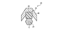
- FIG. 4 is a cross-sectional view schematically showing the end effector according to the first embodiment in a cross section perpendicular to the longitudinal axis.
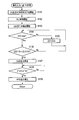
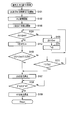
- FIG. 5 is a flowchart showing processing in the energy control device based on an operation input with the operation button according to the first embodiment.
- FIG. 6 is a schematic diagram showing an example of a change over time in acoustic impedance after the output of ultrasonic electric energy and high-frequency electric energy is started simultaneously.
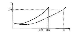
- FIG. 7 is a schematic diagram showing an example of a change with time of high-frequency impedance after the output of ultrasonic electric energy and high-frequency electric energy is started simultaneously.
- FIG. 8 is a schematic diagram showing another example of the change over time in acoustic impedance after the output of ultrasonic electric energy and high-frequency electric energy is started at the same time.
- FIG. 9 is a flowchart showing a process in the energy control device based on an operation input with the operation button according to the first modification.
- FIG. 9 is a flowchart showing a process in the energy control device based on an operation input with the operation button according to the first modification.
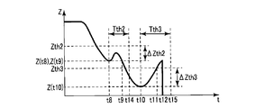
- FIG. 10 is a schematic diagram showing another example of the change over time in acoustic impedance after the output of ultrasonic electric energy and high-frequency electric energy is started simultaneously.
- FIG. 11 is a flowchart showing a process in the energy control device based on an operation input with an operation button according to a second modification.
- FIG. 1 is a diagram showing an energy treatment device (energy treatment system) 1.
- an energy treatment device (medical treatment device) 1 includes an energy treatment tool (handpiece) 2 and an energy control device (energy control unit) 3.
- the energy treatment device 2 has a longitudinal axis C.
- one side is the distal end side (the arrow C1 side in FIG. 1), and the opposite side to the distal end side is the proximal end side (the arrow C2 side in FIG. 1).
- the energy treatment device 2 is detachably connected to the energy control device 3 via the cable 5.
- the energy control device 3 controls the supply of energy (ultrasonic electric energy and high frequency electric energy) to the energy treatment instrument 2.
- the energy treatment device 2 includes a housing 6.
- the housing 6 includes a housing body 7 that extends along the longitudinal axis C, and a grip (fixed handle) 8 that extends from the housing body 7 in a direction intersecting the longitudinal axis C.
- a handle (movable handle) 11 is rotatably attached to the housing 6. As the handle 11 rotates with respect to the housing 6, the handle 11 opens or closes with respect to the grip 8.
- a rotation knob 12 is coupled to the distal end side of the housing body 7 so as to be rotatable about the longitudinal axis C with respect to the housing 6.
- An operation button (operation member) 13 for performing an operation input for supplying energy (treatment energy) from the energy control device 3 to the energy treatment tool 2 is attached to the housing 6.
- a vibrator case 15 is connected to the housing 6 in a state of being inserted into the housing body 7 from the proximal end side.
- One end of the cable 5 is connected to the base end of the vibrator case 15.
- a sheath 16 is connected to the housing 6 in a state of being inserted into the inside of the rotary knob 12 and the inside of the housing body 7 from the distal end side.
- the sheath 16 extends along the longitudinal axis C.
- a vibration transmission member (probe) 17 extends from the inside of the housing body 7 through the inside of the sheath 16 toward the distal end side.
- the vibration transmission member 17 extends along the longitudinal axis C, and a first gripping portion (probe treatment portion) 21 is provided at the distal end portion of the vibration transmission member 17.
- the vibration transmitting member 17 is inserted through the sheath 16 with the first gripping portion 21 protruding from the distal end of the sheath 16 toward the distal end side.
- the 2nd holding part (jaw) 22 is attached to the front-end
- a movable shaft (not shown) extending inside the sheath 16 moves along the longitudinal axis C.
- the second gripping portion 22 rotates with respect to the sheath 16, and the space between the second gripping portion 22 and the first gripping portion 21 opens or closes.
- the end effector 20 that performs treatment using the supplied energy is configured by the first grip portion 21 and the second grip portion 22.
- a treatment target such as a living tissue grasped between the first grasping portion 21 and the second grasping portion 22 is treated with supplied energy.
- the sheath 16, the vibration transmitting member 17 (first holding portion 21), and the second holding portion 22 are rotated around the longitudinal axis C with respect to the housing 6 together with the rotating knob 12. Rotate. Thereby, the angular position around the longitudinal axis C of the end effector 20 is adjusted.
- FIG. 2 is a diagram showing an electrical connection state between the energy treatment device 2 and the energy control device 3 and a configuration for supplying energy to the end effector 20.
- the energy control device 3 includes a control unit 25, an energy source 26, and a storage medium 27 such as a memory.
- the energy source 26 includes ultrasonic electric energy (electric energy for generating ultrasonic vibration by a vibration generating unit 40 described later) and high frequency electric energy (treatment target between the first gripping unit 21 and an electrode member 46 described later). Electric energy for supplying a high-frequency current to the output.
- the control unit 25 includes, for example, a processor including a CPU (Central Processing Unit) or an ASIC (application specific integrated circuit), and can send and receive signals and information to and from the energy source 26 and the storage medium 28 via an interface such as a bus. is there. For this reason, the control unit 25 can detect the output state of energy from the energy source 26 and can control the output state of energy from the energy source 26. The control unit 25 can read information from the storage medium 27 and can write information to the storage medium 27.
- a processor including a CPU (Central Processing Unit) or an ASIC (application specific integrated circuit)
- a switch 31 is provided inside the housing 6.
- the switch 31 is electrically connected to the control unit 25 via signal paths 32A and 32B extending through the inside of the housing 6 and the inside of the cable 5.
- the switch 31 is provided at a position that can be pressed by the operation button 13, and the opening / closing changes based on an operation input by the operation button 13.
- the control unit 25 detects whether or not an operation input is being performed with the operation button 13 by detecting opening and closing of the switch 31 via the signal paths 32A and 32B.
- the control part 25 controls the output state of the energy from the energy source 26 based on the detection result of the presence or absence of the operation input with the operation button 13.
- FIG. 3 is a diagram showing a configuration for controlling the output of energy from the energy source 26.
- the energy source 26 includes an ultrasonic electric energy source (ultrasonic power source) 35 and a high frequency electric energy source (high frequency power source) 36.
- the ultrasonic electric energy source 35 includes, for example, a conversion circuit (driving circuit) that converts electric power from a battery or electric power from an outlet into ultrasonic electric energy (ultrasonic electric power P).
- the control unit 25 controls the output of the ultrasonic electric energy from the ultrasonic electric energy source 35 by controlling the driving of the ultrasonic electric energy source 35.
- the high-frequency electrical energy source 36 includes a conversion circuit (drive circuit) that converts, for example, power from a battery or power from an outlet into high-frequency electrical energy (high-frequency power P ′).
- the control unit 25 controls the output of the high frequency electrical energy from the high frequency electrical energy source 36 by controlling the driving of the high frequency electrical energy source 36.
- a vibration generating unit (ultrasonic transducer) 40 is provided in the vibrator case 15.
- the vibration generating unit 40 is connected to the vibration transmitting member 17 from the base end side inside the housing body 7.
- the vibration generating unit 40 includes (four in this embodiment) piezoelectric elements 41 and ultrasonic electrodes 42A and 42B. Each of the piezoelectric elements 41 is sandwiched between an ultrasonic electrode (first ultrasonic electrode) 42A and an ultrasonic electrode (second ultrasonic electrode) 42B.
- the ultrasonic electrode 42A is connected to the ultrasonic electric energy source 35 of the energy source 26 via an ultrasonic electric path (first ultrasonic electric path) 43A extending through the cable 5.
- the ultrasonic electrode 42 ⁇ / b> B is connected to the ultrasonic electric energy source 35 via an ultrasonic electric path (second ultrasonic electric path) 43 ⁇ / b> B extending through the cable 5.
- ultrasonic electric energy is output from the ultrasonic electric energy source 35 under the control of the control unit 25, ultrasonic electric energy is supplied to the vibration generating unit 40 via the ultrasonic electric paths 43A and 43B.
- the ultrasonic voltage V is applied between the ultrasonic electrode (first ultrasonic electrode) 42A and the ultrasonic electrode (second ultrasonic electrode) 42B, and ultrasonic waves are applied to the ultrasonic electric paths 43A and 43B.
- Current I flows.
- the piezoelectric element 41 converts the ultrasonic current I into ultrasonic vibration
- the vibration generating unit 40 generates ultrasonic vibration.
- the ultrasonic vibration generated by the vibration generator 40 is transmitted from the proximal end side to the distal end side in the vibration transmitting member 17.
- the ultrasonic vibration is transmitted to the first gripping portion 21 of the end effector 20 so that the first gripping portion 21 vibrates in the direction along the longitudinal axis C, for example.
- the end effector 20 can perform treatment using ultrasonic vibration.
- the ultrasonic current I is an alternating current whose flow direction changes periodically.
- FIG. 4 shows the end effector 20 in a cross section perpendicular to the longitudinal axis C.
- FIG. 4 shows a state in which the space between the first grip portion 21 and the second grip portion 22 is closed.
- the second grip 22 is formed of a pad member (contact member) 45 formed of an electrically insulating material such as PEEK (polyether ether ketone) and an electrically conductive material.
- An electrode member 46 to be provided.
- the pad member is formed by closing the second gripping portion 22 with respect to the first gripping portion 21 in a state where the treatment target is not disposed between the first gripping portion 21 and the second gripping portion 22. 45 abuts on the first grip 21. Further, in a state where the pad member 45 is in contact with the first gripping portion 21, the electrode member 46 is separated from the first gripping portion 21 and does not come into contact with the first gripping portion 21.
- the first gripping portion (first high frequency electrode) 21 has a high frequency electrical path (first high frequency electrical current) extending through the inside of the housing 6 and the inside of the cable 5. Path) is connected to the high-frequency electrical energy source 36 via 47A.
- the electrode member (second high-frequency electrode) 46 of the second gripping portion 22 has a high-frequency electric path (second high-frequency electric path) 47B extending through the inside of the housing 6 and the inside of the cable 5. To the high-frequency electric energy source 36.
- the high-frequency electrical energy is output from the high-frequency electrical energy source 36 under the control of the control unit 25, the high-frequency electrical energy is transmitted through the high-frequency electrical paths 47A and 47B to the first gripping part 21 and the electrode member 46 (second gripping). Part 22).
- the high frequency voltage V ′ is applied between the first grip portion 21 and the electrode member 46, and the high frequency current I ′ flows through the high frequency electrical paths 47 ⁇ / b> A and 47 ⁇ / b> B.
- the first grip portion 21 and the electrode member 46 function as high-frequency electrodes of high-frequency electrical energy (high-frequency power P ′) having different potentials relative to each other.
- the end effector 20 can perform treatment using high-frequency electrical energy.
- the high-frequency current I ′ is an alternating current whose flow direction changes periodically.
- the control unit 25 includes an impedance detection unit 51, a switching detection unit 52, and a determination unit 53.
- Each of the impedance detection unit 51, the switching detection unit 52, and the determination unit 53 is formed of, for example, an electronic circuit that forms part of the processor, and performs part of the processing of the processor.
- the impedance detection unit 51 detects the output state of the ultrasonic electric energy from the ultrasonic electric energy source 35 over time, and thereby changes the ultrasonic current I over time and the ultrasonic voltage V over time. To detect. At this time, a change with time of the ultrasonic power P may be detected. Then, using equation (1), the impedance detection unit 51 detects acoustic impedance (ultrasonic impedance) Z over time as impedance in the path of ultrasonic electrical energy (impedance at the vibration generation unit 40) ( calculate).
- the impedance detector 51 detects the output state of the high-frequency electric energy from the high-frequency electric energy source 36 over time, thereby changing the high-frequency current I ′ over time and the high-frequency voltage V ′ over time. To detect. At this time, a change with time of the high-frequency power P ′ may be detected. Then, using the equation (2), the impedance detection unit 51 uses the high frequency impedance (tissue impedance) Z ′ as the impedance (impedance between the first gripping unit 21 and the electrode member 46) in the path of high frequency electrical energy. Is detected (calculated) over time.
- the switching detection unit 52 switches from a gradually decreasing state in which the acoustic impedance Z gradually decreases to a gradually increasing state in which the acoustic impedance Z gradually increases.
- the gradually decreasing state of the acoustic impedance Z is a state in which the acoustic impedance Z gradually decreases with time, and includes a state in which the acoustic impedance Z gradually decreases while including a slight increase or decrease of several tens of ⁇ or less.
- the gradually increasing state of the acoustic impedance Z is a state in which the acoustic impedance Z gradually increases with time, and includes a state in which the acoustic impedance Z gradually increases while including a slight increase or decrease of several tens of ⁇ or less.
- the determination unit 53 Judgment on electrical energy output and high-frequency electrical energy output For example, the determination unit 53 determines whether to stop the output of the ultrasonic electric energy based on the detection result in the impedance detection unit 51 and the detection result in the switching detection unit 52, and the impedance detection unit 51. Whether or not to stop the output of the high-frequency electrical energy is determined based on the detection result at.
- the processing by the control unit 25 including the impedance detection unit 51, the switching detection unit 52, and the determination unit 53 in a state where ultrasonic electric energy and high-frequency electric energy are simultaneously output from the energy source 26 will be described in detail later. To do.
- the operation and effect of the energy treatment device 1 of the present embodiment will be described.
- the operator holds the housing 6 and the handle 11, and inserts the distal end portion of the sheath 16 and the end effector 20 into a body cavity such as the abdominal cavity.
- the angular position about the longitudinal axis C of the end effector 20 is adjusted by the rotary knob 12, and a treatment target such as a biological tissue (blood vessel) is disposed between the first gripping portion 21 and the second gripping portion 22.
- a treatment target such as a biological tissue (blood vessel) is disposed between the first gripping portion 21 and the second gripping portion 22.
- the space between the first gripping portion 21 and the second gripping portion 22 is closed, and between the first gripping portion 21 and the second gripping portion 22. Grasp the treatment target.
- the control unit 25 controls the energy source 26 so that the ultrasonic electric energy is transmitted from the energy source 26. And high-frequency electrical energy are output simultaneously. Thereby, ultrasonic vibration is generated in the vibration generating unit 40, and the generated ultrasonic vibration is transmitted to the end effector 20 (first holding unit 21), and at the same time, the end effector 20 (first holding unit 21 and High frequency electrical energy is supplied to the electrode member 46).
- the ultrasonic electric energy and the high-frequency electric energy are preferably started to be output at the same time, but may not be completely at the same time. That is, “simultaneous” here includes not only completely simultaneous but also substantially simultaneous.
- the end effector 20 coagulates the treatment target by simultaneously using ultrasonic vibration and high-frequency electrical energy, for example, sealing a blood vessel.
- ultrasonic vibration and high-frequency electrical energy for example, sealing a blood vessel.
- frictional heat is generated between the first gripping portion 21 and the first gripping portion 21 that is pressed by the pad member 45 and the first gripping portion 21 that is vibrated by ultrasonic vibration.
- the object to be treated is solidified by the frictional heat.
- the high frequency current I ′ flows through the treatment target between the first grasping portion 21 and the electrode member 46, whereby the treatment target is denatured and solidified.
- FIG. 5 is a flowchart showing processing in the energy control device 3 based on an operation input by the operation button 13.
- the control unit 25 detects ultrasonic electric energy (shown as US in FIG. 5) and high-frequency electric energy (in FIG. 5) from the energy source 26. Simultaneous output of HF is started (step S101). Then, the control unit 25 starts PLL (Phase Locked Loop) control for the ultrasonic electric energy (step S102).
- PLL Phase Locked Loop
- the frequency of the ultrasonic current I is adjusted, and the resonance frequency Fr of the ultrasonic vibration is adjusted. At this time, for example, the resonance frequency Fr of the ultrasonic vibration is adjusted to a frequency that minimizes the acoustic impedance Z in a predetermined frequency region.
- the impedance detection unit 51 (control unit 25) starts detection of the acoustic impedance Z and the high frequency impedance Z ′ (step S103). Thereby, a change with time of the acoustic impedance Z and a change with time of the high-frequency impedance Z ′ are detected.
- the ultrasonic current I and the ultrasonic voltage V (ultrasonic power P) are detected over time, and the acoustic impedance Z is calculated using the equation (1).
- the high-frequency current I ′ and the high-frequency voltage V ′ (high-frequency power P ′) are detected over time, and the high-frequency impedance Z ′ is calculated using Equation (2).
- time t when the PLL control start time is set to zero is set as a variable, and acoustic impedance Z (t) and high-frequency impedance Z ′ (t) at time t are defined. Further, the minimum impedance value Zmin is defined as the minimum value of the acoustic impedance Z after the start of the PLL control and before the time t.
- step S104 It is determined whether or not the impedance value is greater than Zmin (step S104).
- the control unit 25 switching detection unit 52
- the impedance value Zmin is updated (step S105).
- the control unit 25 performs the determination in step S104 again using the updated minimum impedance value Zmin after the time when the acoustic impedance Z becomes the updated minimum impedance value Zmin in step S105.
- step S104 when the acoustic impedance Z (t) at time t is larger than the minimum impedance value Zmin (step S104-Yes), the control unit 25 (determination unit 53) determines the minimum impedance value from the acoustic impedance Z (t). It is determined whether or not the value obtained by subtracting Zmin is greater than or equal to the reference difference value ⁇ Zth (step S106). That is, if the sum of the minimum impedance value Zmin and the reference difference value ⁇ Z is the reference impedance value Zth, the control unit 25 determines whether or not the acoustic impedance Z (t) at time t is equal to or greater than the reference impedance value Zth. to decide.
- the reference difference value ⁇ Zth and the reference impedance value Zth are set based on the value of the minimum impedance value Zmin, the mode of change of the acoustic impedance Z, etc. In one embodiment, the reference difference value ⁇ Zth is 50 ⁇ or more and 60 ⁇ or less. Set by range.
- step S106-No If the value obtained by subtracting the minimum impedance value Zmin from the acoustic impedance Z (t) is smaller than the reference difference value ⁇ Zth (step S106-No), the process returns to step S104. And the control part 25 makes the judgment of step S104 again after the time of becoming the judgment object of step S106.
- the control unit 25 starts from the energy source 26 (ultrasonic electric energy source 35). The output of the ultrasonic electric energy (US) is stopped (step S107). As a result, the ultrasonic vibration is not transmitted to the end effector 20 (the first grip portion 21).
- the control unit 25 determines whether or not it is equal to or higher than a high frequency threshold value Z′th (step S108). If the high-frequency impedance Z ′ (t) is smaller than the threshold value Z′th (step S108—No), the process returns to step S108. And the control part 25 makes the judgment of step S108 again after the time of becoming the judgment object of step S108.
- the control unit 25 outputs the high frequency electrical energy (HF) from the energy source 26 (high frequency electrical energy source 36). Is stopped (step S109). As a result, high-frequency electrical energy is not supplied to the end effector 20 (the first grip portion 21 and the electrode member 46).
- the threshold value Z′th is set based on the manner of change in the high-frequency impedance Z or the like.
- FIG. 6 shows an example of the change over time of the acoustic impedance Z after the output of ultrasonic electric energy and high-frequency electric energy is started simultaneously
- FIG. 7 shows the start of output of ultrasonic electric energy and high-frequency electric energy simultaneously.
- the horizontal axis indicates the time t when the PLL control start time is zero.
- the acoustic impedance Z is shown on the vertical axis
- the high frequency impedance Z ′ is shown on the vertical axis.
- the acoustic impedance Z changes as shown by the solid line in FIG. 6, and the high-frequency impedance Z ′ changes as shown by the solid line in FIG. .
- the resonance frequency Fr of the ultrasonic vibration is adjusted by the PLL control, and the acoustic impedance Z begins to gradually decrease with time. Then, the gradually decreasing state in which the acoustic impedance Z gradually decreases with time continues for a while. And if the 1st holding
- the acoustic impedance Z is switched from a gradually decreasing state in which the acoustic impedance Z gradually decreases with time to a gradually increasing state in which the acoustic impedance Z gradually increases with time. Then, the gradually increasing state of the acoustic impedance Z continues for a while. In the example of FIG. 6, the acoustic impedance Z is switched from the gradually decreasing state to the gradually increasing state at time t1.
- the energy control device 3 performs the processing shown in FIG. 5 based on the operation input with the operation button 13. For this reason, when the acoustic impedance Z changes as shown by the solid line in FIG. 6, in the gradual decrease state of the acoustic impedance Z before the time t1, the processing of steps S104 and S105 is performed by the control unit 25 (switching detection unit 52). Is repeated over time. That is, in the gradual decrease state of the acoustic impedance Z before the time t1, the process of updating (setting) the acoustic impedance Z (t) at the time t as the minimum impedance value Zmin is continuously performed. Then, the acoustic impedance Z (t1) at time t1 is set as the minimum impedance value Zmin.
- the control unit 25 (the switching detection unit 52) has switched the acoustic impedance Z from the gradually decreasing state to the gradually increasing state at time t1. Is detected.
- the control unit 25 sets the reference difference value ⁇ Zth and the reference impedance value Zth.
- the reference difference value ⁇ Zth1 and the reference impedance value Zth1 are set.
- the reference impedance value Zth1 is the sum of the acoustic impedance Z (t1) at the time t1 and the reference difference value ⁇ Zth1, and is larger than the acoustic impedance Z (t1) at the time t1.
- the process of step S104 and the process of step S106 using the set reference difference value ⁇ Zth1 and reference impedance value Zth1 are repeated over time.
- the control unit 25 determines that the acoustic impedance Z (t2) at the time t2 is the same as the reference impedance value Zth1. That is, it is detected that the value obtained by subtracting the acoustic impedance Z (t1) at time t1 set as the minimum impedance value Zmin from the acoustic impedance Z (t2) at time t2 is the same as the reference difference value ⁇ Zth1. Thereby, the control unit 25 (determination unit 53) determines that the acoustic impedance Z has reached the reference impedance value Zth1 at time t2.
- the control part 25 stops the output of the ultrasonic electric energy (US) from the energy source 26 at the time t2 immediately after the time t2 or the time t2 by the process in step S107. Therefore, in this embodiment, the change of the acoustic impedance Z from the gradually decreasing state to the gradually increasing state at the time t1 is detected, and the acoustic impedance Z is the reference impedance value at the time t2 after the switching to the gradually increasing state. Based on having reached Zth1, the control unit 25 stops the output of the ultrasonic electric energy.
- US ultrasonic electric energy
- the output of the ultrasonic electric energy is stopped based on the change over time from the impedance value Z (t1) set as the minimum impedance value Zmin of the acoustic impedance Z after the time t1 when switching to the gradually increasing state. I am letting. Then, the control unit 25 stops the output of the ultrasonic electric energy after the time t1 when switching to the gradual increase state and while the acoustic impedance Z is in the gradual increase state.
- the control unit 25 determines that the high-frequency impedance Z ′ (t4) at the time t4 is the same as the threshold value Z′th1. Thereby, the control unit 25 (determination unit 53) determines that the high-frequency impedance Z ′ has reached the threshold value Z′th1 at time t4.
- control part 25 stops the output of the high frequency electric energy (HF) from the energy source 26 in the time t4 immediately after the time t4 or the time t4 by the process in step S109. Therefore, in the present embodiment, the control unit 25 stops the output of the high-frequency electrical energy based on the fact that the high-frequency impedance Z ′ has reached the threshold value Z′th1 at time t4.
- HF high frequency electric energy
- the time-dependent change of the high-frequency impedance Z ′ in the case where the ultrasonic electric energy is not output and only the high-frequency electric energy is output is indicated by a one-dot chain line in FIG.
- a long time is required until the temperature of the treatment target rises to some extent, and a long time is required until the high-frequency impedance Z ′ reaches the threshold value Z′th (Z′th1). Cost.
- the frictional heat generated by the ultrasonic vibration acts on the treatment target in addition to the heat generated by the high frequency electric energy. .
- the temperature of the treatment target rises quickly, and the high-frequency impedance Z ′ quickly reaches the threshold value Z′th.
- the high-frequency impedance Z ′ reaches the threshold value Z′th1 at time t6, whereas the ultrasonic electrical energy as in this embodiment.
- the high-frequency impedance Z ′ reaches the threshold value Z′th1 at time t4 before time t6.
- the treatment target By rapidly increasing the temperature of the treatment target, the treatment target is rapidly coagulated after the output of high-frequency electrical energy is started, and blood vessels and the like can be quickly sealed.
- high-frequency electrical energy When only high-frequency electrical energy is output, it takes about 5 seconds from the start of energy output until the high-frequency impedance Z ′ reaches the threshold value Z′th.
- output of ultrasonic electrical energy and high-frequency electrical energy starts simultaneously.
- the high frequency impedance Z ′ reaches the threshold value Z′th in about 3 seconds from the start of energy output.
- the treatment target starts to be partially separated by the frictional heat caused by the ultrasonic vibration.
- the pad member 45 of the second gripping portion 22 comes into contact with the first gripping portion 21 that is vibrated by ultrasonic vibration, and the pad member 45 is denatured by frictional heat.
- the acoustic impedance Z is switched from a gradually increasing state to a gradually decreasing state, and a peak (maximum) of the acoustic impedance Z with time is generated.
- the acoustic impedance Z (t7) at time t7 becomes the peak value of the acoustic impedance Z. Then, after a while since the peak of the acoustic impedance Z occurs, the treatment target is completely separated.
- the switching of the acoustic impedance Z from the gradually decreasing state to the gradually increasing state is detected, and it is detected that a local minimum (valley) has occurred in the change of the acoustic impedance Z over time.
- the output of the ultrasonic electric energy from the energy source 26 is rapidly stopped based at least on the occurrence of the minimum (valley) in the change in the acoustic impedance Z with time. For this reason, the output of ultrasonic electric energy is stopped during the gradual increase state of the acoustic impedance Z after the gradual increase state of the acoustic impedance Z, and before the time-dependent peak of the acoustic impedance Z occurs (for example, the time t7).
- the output of the ultrasonic electrical energy is stopped.
- the treatment target is coagulated using high-frequency electrical energy and ultrasonic vibration simultaneously, the treatment target is appropriately solidified (sealed) without being separated by frictional heat caused by the ultrasonic vibration. can do.
- the output of the ultrasonic electric energy is stopped based on the fact that the acoustic impedance Z has reached the reference impedance value Zth after the switching to the gradual increase state.
- the acoustic impedance (for example, Z (t1)) is about 1300 ⁇ at the minimum time (for example, t1) when the acoustic impedance Z is switched from the gradually decreasing state to the gradually increasing state.
- the acoustic impedance (for example, Z (t7)) is about 1450 ⁇ at the peak time (for example, t7) when switching from the gradually increasing state to the gradually decreasing state.
- the acoustic impedance at the peak (for example, Z (t7)) is about 150 ⁇ larger than the acoustic impedance at the minimum (for example, Z (t1)).
- the difference between the acoustic impedance at the peak (for example, Z (t7)) and the acoustic impedance at the minimum (for example, Z (t1)) is about 135 ⁇ at the minimum.
- the reference difference value ⁇ Zth is set in the range of 50 ⁇ to 135 ⁇
- the reference impedance value Zth is the reference difference when the acoustic impedance (for example, Z (t1)) is minimized (when switching to the gradually increasing state).
- FIG. 8 is a view showing an example different from FIG. 6 of the change with time of the acoustic impedance Z after the output of ultrasonic electric energy and high-frequency electric energy is started at the same time.
- the time t when the PLL control start time is zero is shown on the horizontal axis
- the acoustic impedance Z is shown on the vertical axis.
- the state of the treatment target changes as the temperature of the treatment target rises to some extent. For this reason, at time t10, the acoustic impedance Z is switched from the gradually decreasing state to the gradually increasing state, and the acoustic impedance Z is minimized.
- the acoustic impedance Z is switched from the gradually decreasing state to the gradually increasing state, and the acoustic impedance Z is minimized. That is, the acoustic impedance Z is minimized (from the gradually decreasing state to the gradually increasing state) before the time point when the acoustic impedance Z is minimized due to the change in the state of the treatment target due to the temperature increase of the treatment target (for example, t10). Switching) may occur.
- the acoustic impedance Z becomes minimum at time t8
- the acoustic impedance Z starts to gradually decrease again, and the acoustic impedance Z continues to decrease until time t10.
- the energy control device 3 performs the processing shown in FIG. 5 based on the operation input with the operation button 13. For this reason, when the acoustic impedance Z changes as shown in FIG. 8, in the gradual decrease state of the acoustic impedance Z before the time t8, the control unit 25 (switching detection unit 52) performs the processing of steps S104 and S105 over time. Repeatedly. Then, the control unit 25 (switching detection unit 52) sets the acoustic impedance Z (t8) at time t8 as the minimum impedance value Zmin, and the acoustic impedance Z is switched from the gradually decreasing state to the gradually increasing state at time t8. Is detected.
- control unit 25 determines whether the control unit 25 has the reference difference value ⁇ Zth2 and the reference impedance value Zth2.
- the process of step S104 and the process of step S106 using the set reference difference value ⁇ Zth2 and reference impedance value Zth2 are repeated over time.
- the control unit 25 determines that the acoustic impedance Z (t8) at the time t9 is set as the minimum impedance value Zmin by the process of step S104. Judge that it became the following. Then, the acoustic impedance Z (t9) at time t9 is updated as the minimum impedance value Zmin by the process of step S105.
- the minimum impedance value Zmin is updated to the acoustic impedance Z (t9), the processes of steps S104 and S105 are repeatedly performed with time in the gradual decrease state of the acoustic impedance Z from time t9 to time t10.
- control unit 25 (switching detection unit 52) updates the acoustic impedance Z (t10) at time t10 as the minimum impedance value Zmin, and the acoustic impedance Z is switched from the gradually decreasing state to the gradually increasing state at time t10. Is detected.
- control unit 25 (determination unit 53) sets the reference difference value ⁇ Zth3 and the reference impedance value Zth3. After time t10, the process of step S104 and the process of step S106 using the set reference difference value ⁇ Zth3 and reference impedance value Zth3 are repeated over time.
- the control unit 25 determines that the acoustic impedance Z (t11) at time t11 is the same as the reference impedance value Zth3, and the acoustic impedance Z is detected at time t11. It is determined that the reference impedance value Zth3 has been reached. And the control part 25 stops the output of the ultrasonic electrical energy (US) from the energy source 26 in the time t12 immediately after the time t11 or the time t11 by the process in step S107.
- US ultrasonic electrical energy
- the control unit 25 determines the first impedance value (for example, Z (t8) set as the minimum impedance value Zmin of the acoustic impedance Z after switching to the gradual increase state. Whether or not to stop the output of the ultrasonic electric energy is determined based on the change over time from)). Then, the control unit 25 (the switching detection unit 52) performs the second operation below the first impedance value (for example, Z (t8)) in which the acoustic impedance Z is set as the minimum impedance value Zmin after the switching to the gradual increase state. Is detected, the minimum impedance value Zmin is updated to the second impedance value (for example, Z (t10)).
- the first impedance value for example, Z (t8) set as the minimum impedance value Zmin of the acoustic impedance Z after switching to the gradual increase state.
- control unit 25 determines unit 53 updates the minimum impedance value Zmin of the acoustic impedance Z after the time (t10) when the acoustic impedance Z reaches the second impedance value (Z (t10)). Whether or not to stop the output of the ultrasonic electric energy is determined based on the change with time from the impedance value of 2 (Z (t10)).
- the output of the ultrasonic electric energy can be stopped at an appropriate timing after the state of the treatment target is changed due to an increase in the temperature of the treatment target.
- the energy control device 3 performs the process shown in FIG. 9 based on the operation input from the operation button 13.
- the processes of steps S111 to S113 are performed.
- a count time T is defined in which the switching time is zero.
- step S104-No when the acoustic impedance Z (t) at time t is equal to or smaller than the minimum impedance value Zmin in step S104 (step S104-No), the control unit 25 (switching detection unit 52) The acoustic impedance Z (t) is updated as the minimum impedance value Zmin (step S105), and the count time T is held at zero or the count time T is reset to zero (step S111).
- step S111 the process returns to step S104.
- the control unit 25 performs the determination in step S104 again using the updated minimum impedance value Zmin after the time when the acoustic impedance Z becomes the updated minimum impedance value Zmin in step S105.
- step S104 when the acoustic impedance Z (t) at time t is larger than the minimum impedance value Zmin (step S104-Yes), the control unit 25 (determination unit 53) starts or counts the count time T. Continue (step S112). Note that the count time T is not counted in the state where the processes of steps S104, S105, and S111 are repeated over time.
- the control unit 25 determineation unit 53 performs the process of step S106 described above in the first embodiment.
- step S106 whether the value obtained by subtracting the minimum impedance value Zmin from the acoustic impedance Z (t) is equal to or greater than the reference difference value ⁇ Zth (whether the acoustic impedance Z (t) at time t is equal to or greater than the reference impedance value Zth) ) Is determined (step S106).
- the control unit 25 determines that the count time T is a predetermined set time Tth. It is determined whether or not this is the case (step S113). That is, it is determined whether or not a predetermined set time Tth has elapsed after the acoustic impedance Z is switched to the gradually increasing state.
- the predetermined set time Tth is set based on the value of the minimum impedance value Zmin, the manner of change of the acoustic impedance Z, and the like.
- step S113-No If the count time T at time t is smaller than the predetermined set time Tth (step S113-No), the process returns to step S104. And the control part 25 makes the judgment of step S104 again after the time of becoming the judgment object of step S106 and step S113.
- the control unit 25 uses the ultrasonic electric energy (US) from the energy source 26 (ultrasonic electric energy source 35). Is stopped (step S107).
- US ultrasonic electric energy
- step S106 when the value obtained by subtracting the minimum impedance value Zmin from the acoustic impedance Z (t) is equal to or larger than the reference difference value ⁇ Zth (step S106-Yes), the control unit 25 performs the ultrasonic electric power from the energy source 26.
- the output of energy (US) is stopped (step S107).
- the output of the high-frequency electric energy (HF) is based on the fact that the high-frequency impedance Z ′ (t) is equal to or higher than the threshold value Z′th. Stopped.
- the energy control device 3 performs the process shown in FIG. 9 based on the operation input with the operation button 13. For this reason, when the acoustic impedance Z changes as shown by the solid line in FIG. 6, as in the first embodiment, the control unit 25 (switching detection unit 52) detects the acoustic impedance Z (t1) at time t1. Is set as the minimum impedance value Zmin, and it is detected that the acoustic impedance Z is switched from the gradually decreasing state to the gradually increasing state at time t1. At this time, in this modification, the control unit 25 (determination unit 53) sets the reference difference value ⁇ Zth1 and the reference impedance value Zth1, and sets a predetermined set time Tth1.
- the count time T in which the time t1 when the acoustic impedance Z is switched to the gradually increasing state is set to zero is counted by the process of step S112. Then, after time t1, the processes in steps S104 and S112, the process in step S106 using the set reference difference value ⁇ Zth1 and the reference impedance value Zth1, and the process in step S113 using a predetermined set time Tth1 Is repeated over time.
- the control unit 25 determines that the acoustic impedance Z (t2) at time t2 is the same as the reference impedance value Zth1, and the acoustic impedance Z is detected at time t2. It is determined that the reference impedance value Zth1 has been reached. Then, by the processing in step S107, the control unit 25 stops the output of ultrasonic electric energy (US) from the energy source 26 at time t2 or time t3 immediately after time t2. In addition, when the acoustic impedance Z changes as shown by the solid line in FIG. 6, the ultrasonic electric energy is changed before the time t13 when a predetermined set time Tth1 has elapsed since the switching of the acoustic impedance Z (ie, time t1). Output is stopped.
- US ultrasonic electric energy
- the control unit 25 sets the acoustic impedance Z (t8) at time t8 to the minimum impedance as in the first embodiment.
- a value Zmin is set, and it is detected that the acoustic impedance Z is switched from the gradually decreasing state to the gradually increasing state at time t8.
- the control unit 25 determines the reference difference value ⁇ Zth2 and the reference impedance value Zth2, and sets a predetermined set time Tth2.
- the count time T in which the time t8, which is the time when the acoustic impedance Z is switched to the gradually increasing state, is zero is counted by the process of step S112. Then, after time t8, the processing in steps S104 and S112, the processing in step S106 using the set reference difference value ⁇ Zth2 and the reference impedance value Zth2, and the processing in step S113 using a predetermined setting time Tth2 Is repeated over time.
- the control unit 25 repeats the processes of steps S104, S112, S106, and S113, so that the acoustic impedance Z is changed from the time t8 when the acoustic impedance Z is gradually increased to a predetermined value. It is determined that the acoustic impedance Z has not reached the reference impedance value Zth2 until the set time Tth2 has elapsed.
- control unit 25 determines that the acoustic impedance Z (t9) is equal to or less than the acoustic impedance Z (t8) set as the minimum impedance value Zmin before the time t14 when the predetermined set time Tth2 has elapsed from the time t8. Judge that Then, the acoustic impedance Z (t9) at time t9 is updated as the minimum impedance value Zmin by the process of step S105, and the count time T is reset to zero by the process of step S111. Then, in the gradual decrease state of the acoustic impedance Z from the time t9 to the time t10, the processes of steps S104, S105, and S111 are repeatedly performed with time.
- the control unit 25 (switching detection unit 52) updates the acoustic impedance Z (t10) at time t10 as the minimum impedance value Zmin, and the acoustic impedance Z is switched from the gradually decreasing state to the gradually increasing state at time t10. Is detected.
- the control unit 25 (determination unit 53) sets the reference difference value ⁇ Zth3 and the reference impedance value Zth3, and sets a predetermined set time Tth3.
- the count time T in which the time t10, which is the time when the acoustic impedance Z is switched to the gradually increasing state, is set to zero is counted by the process of step S112.
- the control unit 25 determines that the acoustic impedance Z (t11) at time t11 is the same as the reference impedance value Zth3, and the acoustic impedance Z is detected at time t11. It is determined that the reference impedance value Zth3 has been reached. And the control part 25 stops the output of the ultrasonic electrical energy (US) from the energy source 26 in the time t12 immediately after the time t11 or the time t11 by the process in step S107. In addition, when the acoustic impedance Z changes as shown in FIG. 8, the output of the ultrasonic electric energy is generated before the time t15 when the predetermined set time Tth3 has elapsed since the switching of the acoustic impedance Z (that is, the time t10). Stopped.
- FIG. 10 is a diagram showing an example different from FIGS. 6 and 8 of the change over time of the acoustic impedance Z after the output of ultrasonic electric energy and high-frequency electric energy is started at the same time.
- the time t when the PLL control start time is zero is shown on the horizontal axis
- the acoustic impedance Z is shown on the vertical axis.
- the state of the treatment target changes as the temperature of the treatment target rises to some extent. For this reason, at time t16, the acoustic impedance Z is switched from the gradually decreasing state to the gradually increasing state, and the acoustic impedance Z is minimized.
- the acoustic impedance Z may hardly increase after the local minimum occurs at time t16.
- the energy control device 3 performs the process shown in FIG. 9 based on the operation input with the operation button 13. For this reason, when the acoustic impedance Z changes as shown in FIG. 10, in the gradual decrease state of the acoustic impedance Z before time t16, the control unit 25 (switching detection unit 52) performs steps S104, S105, and S111. Is repeated over time. Then, the control unit 25 (switching detection unit 52) sets the acoustic impedance Z (t16) at time t16 as the minimum impedance value Zmin, and the acoustic impedance Z is switched from the gradually decreasing state to the gradually increasing state at time t16. Is detected.
- control unit 25 sets the reference difference value ⁇ Zth4 and the reference impedance value Zth4, and sets a predetermined set time Tth4. Further, the count time T in which the time t16, which is the time when the acoustic impedance Z is switched to the gradually increasing state, is set to zero by the process of step S112. After time t16, the processes in steps S104 and S112, the process in step S106 using the set reference difference value ⁇ Zth4 and the reference impedance value Zth4, and the process in step S113 using a predetermined set time Tth4. Is repeated over time.
- the acoustic impedance Z when the acoustic impedance Z changes as shown in FIG. 10, the acoustic impedance Z hardly increases from the time t16 when switching to the gradual increase state, so the acoustic impedance Z does not reach the reference impedance value Zth4. However, the acoustic impedance Z does not become lower than the impedance value Z (t16) set as the minimum impedance value Zmin until the predetermined set time Tth4 elapses from the time t16 (that is, from the time t16 to the time t17).
- control unit 25 determines unit 53 performs the acoustic impedance until a predetermined set time Tth4 has elapsed from the time when the acoustic impedance Z is switched to the gradual increase state (ie, time t16) by the processes of steps S104 and S113. It is determined that Z is continuously maintained at a value larger than the minimum impedance value Zmin (that is, impedance value Z (t16)). And the control part 25 stops the output of the ultrasonic electrical energy (US) from the energy source 26 in the time t17 immediately after the time t17 or the time t17 by the process in step S107.
- US ultrasonic electrical energy
- the switching from the gradually decreasing state to the gradually increasing state of the acoustic impedance Z at time t1 is detected, and after the switching to the gradually increasing state.
- the control unit 25 stops the output of the ultrasonic electric energy. For this reason, this modification also has the same operations and effects as those of the first embodiment.
- the control unit 25 stops the output of the ultrasonic electric energy based on the fact that the acoustic impedance Z is continuously maintained at a value larger than the minimum impedance value Zmin until the set time Tth4 elapses.
- the output of the ultrasonic electric energy is stopped based at least on the fact that the predetermined set time Tth4 has elapsed from the time when the acoustic impedance Z is switched to the gradually increasing state (ie, time t16).
- the energy control device 3 performs the process shown in FIG. 11 based on the operation input from the operation button 13. Similar to the first modification, in the present modification, when the acoustic impedance Z (t) at time t is equal to or smaller than the minimum impedance value Zmin in step S104 (step S104-No), the control unit 25 (switching detection) The unit 52) updates the acoustic impedance Z (t) at time t as the minimum impedance value Zmin (step S105), holds the count time T at zero, or resets the count time T to zero (step S111). . When the process of step S111 is performed, the process returns to step S104.
- step S104 when the acoustic impedance Z (t) at time t is larger than the minimum impedance value Zmin (step S104-Yes), the control unit 25 (determination unit 53) is the same as in the first modification.
- the counting of the counting time T is started or the counting is continued (step S112). Note that the count time T is not counted in the state where the processes of steps S104, S105, and S111 are repeated over time. However, in this modification, the process (judgment) of step S106 performed in the first modification is not performed. For this reason, if the process of step S112 is performed, the control part 25 (determination part 53) will judge whether the count time T is more than the predetermined setting time Tth (step S113). That is, it is determined whether or not a predetermined set time Tth has elapsed after the acoustic impedance Z is switched to the gradually increasing state.
- step S113—No If the count time T at time t is smaller than the predetermined set time Tth (step S113—No), the process returns to step S104. And the control part 25 makes the judgment of step S104 again after the time of becoming the judgment object of step S113. On the other hand, when the count time T at the time t is equal to or longer than the predetermined set time Tth (step S113—Yes), the control unit 25 uses the ultrasonic electric energy (US) from the energy source 26 (ultrasonic electric energy source 35). Is stopped (step S107).
- US ultrasonic electric energy
- the output of the high-frequency electric energy is based on the fact that the high-frequency impedance Z ′ (t) is equal to or higher than the threshold value Z′th. Stopped.
- the energy control device 3 performs the process shown in FIG. 11 based on the operation input with the operation button 13. For this reason, when the acoustic impedance Z changes as shown by the solid line in FIG. 6, the control unit 25 (switching detection unit 52), as in the above-described embodiment, the acoustic impedance Z (t1) at time t1. Is set as the minimum impedance value Zmin, and it is detected that the acoustic impedance Z is switched from the gradually decreasing state to the gradually increasing state at time t1. At this time, in the present modification, the control unit 25 (determination unit 53) sets a predetermined set time Tth1.
- the count time T in which the time t1 when the acoustic impedance Z is switched to the gradually increasing state is set to zero is counted by the process of step S112. Then, after time t1, the processes of steps S104 and S112 and the process of step S113 using a predetermined set time Tth1 are repeated over time.
- the control unit 25 determines unit 53. minimizes the acoustic impedance Z until the predetermined set time Tth1 has elapsed from the time t1 (between the time t1 and the time t13). It is determined that the impedance value is continuously maintained at a value larger than the impedance value Zmin (impedance value Z (t1)). And the control part 25 stops the output of the ultrasonic electric energy (US) from the energy source 26 immediately after the time t13 or the time t13 by the process in step S107.
- US ultrasonic electric energy
- the control unit 25 uses the acoustic impedance Z (t8) at time t8 as the minimum impedance value Zmin, as in the above-described embodiment. It is detected that the acoustic impedance Z is switched from the gradually decreasing state to the gradually increasing state at time t8.
- the control unit 25 determineation unit 53
- the count time T in which the time t8, which is the time when the acoustic impedance Z is switched to the gradually increasing state, is zero is counted by the process of step S112. Then, after time t8, the processes of steps S104 and S112 and the process of step S113 using a predetermined set time Tth2 are repeated over time.
- the control unit 25 repeats the processes of steps S104, S112, and S113, so that a predetermined set time from the time t8 when the acoustic impedance Z is switched to the gradually increasing state. It is determined that the acoustic impedance Z (t9) is equal to or lower than the acoustic impedance Z (t8) set as the minimum impedance value Zmin before time t14 when Tth2 has elapsed. Then, the acoustic impedance Z (t9) at time t9 is updated as the minimum impedance value Zmin by the process of step S105, and the count time T is reset to zero by the process of step S111.
- the control unit 25 (switching detection unit 52) updates the acoustic impedance Z (t10) at time t10 as the minimum impedance value Zmin, and the acoustic impedance Z is switched from the gradually decreasing state to the gradually increasing state at time t10. Is detected.
- the control unit 25 (determination unit 53) sets a predetermined set time Tth3.
- the processing of step 112 counts the count time T when the time t10 when the acoustic impedance Z is switched to the gradually increasing state is zero. Then, after time t10, the processes of steps S104 and S112 and the process of step S113 using a predetermined set time Tth3 are repeated over time.
- the control unit 25 determines unit 53. minimizes the acoustic impedance Z until the predetermined set time Tth3 has elapsed from the time t10 (between the time t10 and the time t15). It is determined that the impedance value is continuously maintained at a value larger than the impedance value Zmin (impedance value Z (t10)). And the control part 25 stops the output of the ultrasonic electrical energy (US) from the energy source 26 immediately after time t15 or time t15 by the process in step S107.
- US ultrasonic electrical energy
- the control unit 25 sets the acoustic impedance Z (t16) at time t16 as the minimum impedance value Zmin, and at time t16. It is detected that the acoustic impedance Z is switched from the gradually decreasing state to the gradually increasing state. At this time, the control unit 25 (determination unit 53) sets a predetermined set time Tth4. Further, the count time T in which the time t16, which is the time when the acoustic impedance Z is switched to the gradually increasing state, is set to zero by the process of step S112. Then, after time t16, the processes of steps S104 and S112 and the process of step S113 using a predetermined set time Tth4 are repeated over time.
- the control unit 25 determines unit 53. minimizes the acoustic impedance Z until the predetermined set time Tth4 has elapsed from the time t16 (between the time t16 and the time t17). It is determined that the impedance value is continuously maintained at a value larger than the impedance value Zmin (impedance value Z (t16)). And the control part 25 stops the output of the ultrasonic electrical energy (US) from the energy source 26 in the time t17 immediately after the time t17 or the time t17 by the process in step S107.
- US ultrasonic electrical energy
- the energy treatment device (1) is configured such that the ultrasonic electric energy and the high-frequency electric energy can be output, and the ultrasonic electric energy is supplied from the energy source (26). It is possible to perform treatment using the vibration generator (40) that generates ultrasonic vibrations, and the ultrasonic vibration generated by the vibration generator (40) and high-frequency electrical energy supplied from the energy source (26).
- An end effector (20) The impedance detector (51) detects the acoustic impedance (Z) over time in a state where the ultrasonic electric energy is output from the energy source (26), and the high-frequency electric energy is output from the energy source (26). In this state, the high frequency impedance (Z ′) is detected over time.
- the switching detection unit (52) Based on the detection result of the acoustic impedance (Z) in the impedance detection unit (51), the switching detection unit (52) causes the acoustic impedance (Z) to gradually decrease from a gradually decreasing state in which the acoustic impedance (Z) gradually decreases. It detects that it switched to the gradual increase state which increases gradually.
- the control unit (25) controls the output state of ultrasonic electric energy and the output state of high-frequency electric energy from the energy source (26). Then, the control unit (25) gradually increases from the gradually decreasing state of the acoustic impedance (Z) by the switching detection unit (52) in a state where the ultrasonic electric energy and the high frequency electric energy are simultaneously output from the energy source (26).
- the output of the ultrasonic electric energy is stopped based at least on the detection of the switch to the state, and the high frequency impedance (Z ′) detected by the impedance detection unit (51) is set to a threshold value (Z ′).
- the output of the high-frequency electric energy is stopped based on the fact that th) has been reached.
Landscapes
- Health & Medical Sciences (AREA)
- Life Sciences & Earth Sciences (AREA)
- Surgery (AREA)
- Engineering & Computer Science (AREA)
- Animal Behavior & Ethology (AREA)
- Veterinary Medicine (AREA)
- Nuclear Medicine, Radiotherapy & Molecular Imaging (AREA)
- Public Health (AREA)
- Biomedical Technology (AREA)
- General Health & Medical Sciences (AREA)
- Medical Informatics (AREA)
- Molecular Biology (AREA)
- Heart & Thoracic Surgery (AREA)
- Dentistry (AREA)
- Mechanical Engineering (AREA)
- Physics & Mathematics (AREA)
- Otolaryngology (AREA)
- Plasma & Fusion (AREA)
- Radiology & Medical Imaging (AREA)
- Surgical Instruments (AREA)
Abstract
Selon l'invention une partie détection de commutation d'un dispositif de traitement par énergie, détecte sur la base de résultats de détection d'une impédance acoustique, une commutation d'un état de réduction vers un état d'augmentation de ladite impédance acoustique. Dans un état de sortie simultanée d'une énergie électrique ultrasonore et d'une énergie électrique haute fréquence provenant d'une source d'énergie, une partie commande stoppe la sortie de ladite énergie électrique ultrasonore sur la base d'une détection de commutation dudit état de réduction vers ledit état d'augmentation de ladite impédance acoustique, et stoppe la sortie de ladite énergie électrique haute fréquence sur la base de l'arrivée de l'impédance acoustique à une valeur seuil établie.
Priority Applications (4)
| Application Number | Priority Date | Filing Date | Title |
|---|---|---|---|
| EP16789495.5A EP3287085A4 (fr) | 2015-05-07 | 2016-04-15 | Dispositif de traitement par énergie, et dispositif de commande d'énergie |
| CN201680026383.7A CN107530105B (zh) | 2015-05-07 | 2016-04-15 | 能量处置装置以及能量控制装置 |
| JP2016561878A JP6132991B2 (ja) | 2015-05-07 | 2016-04-15 | エネルギー処置装置及びエネルギー制御装置 |
| US15/788,069 US10045815B2 (en) | 2015-05-07 | 2017-10-19 | Energy treatment device and energy control device |
Applications Claiming Priority (2)
| Application Number | Priority Date | Filing Date | Title |
|---|---|---|---|
| JP2015094910 | 2015-05-07 | ||
| JP2015-094910 | 2015-05-07 |
Related Child Applications (1)
| Application Number | Title | Priority Date | Filing Date |
|---|---|---|---|
| US15/788,069 Continuation US10045815B2 (en) | 2015-05-07 | 2017-10-19 | Energy treatment device and energy control device |
Publications (1)
| Publication Number | Publication Date |
|---|---|
| WO2016178359A1 true WO2016178359A1 (fr) | 2016-11-10 |
Family
ID=57217648
Family Applications (1)
| Application Number | Title | Priority Date | Filing Date |
|---|---|---|---|
| PCT/JP2016/062129 WO2016178359A1 (fr) | 2015-05-07 | 2016-04-15 | Dispositif de traitement par énergie, et dispositif de commande d'énergie |
Country Status (5)
| Country | Link |
|---|---|
| US (1) | US10045815B2 (fr) |
| EP (1) | EP3287085A4 (fr) |
| JP (1) | JP6132991B2 (fr) |
| CN (1) | CN107530105B (fr) |
| WO (1) | WO2016178359A1 (fr) |
Cited By (2)
| Publication number | Priority date | Publication date | Assignee | Title |
|---|---|---|---|---|
| WO2018217601A1 (fr) * | 2017-05-22 | 2018-11-29 | Ethicon Llc | Instrument combiné ultrasonore et électrochirurgical pourvu d'une électrode de bras de serrage |
| WO2019142251A1 (fr) * | 2018-01-17 | 2019-07-25 | オリンパス株式会社 | Dispositif de commande et procédé de fonctionnement d'un dispositif de commande |
Families Citing this family (2)
| Publication number | Priority date | Publication date | Assignee | Title |
|---|---|---|---|---|
| CN109259849B (zh) * | 2018-08-28 | 2021-01-05 | 重庆金山科技(集团)有限公司 | 电外科能量发生器的控制系统 |
| CN114191041B (zh) * | 2021-12-09 | 2024-04-02 | 上海益超医疗器械有限公司 | 向外科器械输出驱动信号的方法、设备、装置及电子设备 |
Citations (4)
| Publication number | Priority date | Publication date | Assignee | Title |
|---|---|---|---|---|
| JP2009247887A (ja) * | 2008-04-07 | 2009-10-29 | Olympus Medical Systems Corp | 外科手術装置 |
| JP2011125714A (ja) * | 2009-12-16 | 2011-06-30 | Tyco Healthcare Group Lp | 組織密閉のためのシステムおよび方法 |
| WO2012108295A1 (fr) * | 2011-02-10 | 2012-08-16 | オリンパスメディカルシステムズ株式会社 | Dispositif chirurgical haute fréquence et dispositif chirurgical |
| JP2012533346A (ja) * | 2009-07-15 | 2012-12-27 | エシコン・エンド−サージェリィ・インコーポレイテッド | 超音波手術器具のための電気外科手術用電気発生器 |
Family Cites Families (7)
| Publication number | Priority date | Publication date | Assignee | Title |
|---|---|---|---|---|
| US5558671A (en) * | 1993-07-22 | 1996-09-24 | Yates; David C. | Impedance feedback monitor for electrosurgical instrument |
| US5540684A (en) * | 1994-07-28 | 1996-07-30 | Hassler, Jr.; William L. | Method and apparatus for electrosurgically treating tissue |
| US20080058803A1 (en) * | 2006-08-30 | 2008-03-06 | Kenichi Kimura | Surgical instrument and surgical instrument driving method |
| US20090259221A1 (en) * | 2008-04-15 | 2009-10-15 | Naoko Tahara | Power supply apparatus for operation |
| US8372070B2 (en) * | 2008-06-26 | 2013-02-12 | Olympus Medical Systems Corp. | Surgical system and surgical operation method |
| US8308721B2 (en) * | 2008-12-04 | 2012-11-13 | Olympus Medical Systems Corp. | Surgical system and surgical method |
| US9017326B2 (en) * | 2009-07-15 | 2015-04-28 | Ethicon Endo-Surgery, Inc. | Impedance monitoring apparatus, system, and method for ultrasonic surgical instruments |
-
2016
- 2016-04-15 EP EP16789495.5A patent/EP3287085A4/fr not_active Withdrawn
- 2016-04-15 JP JP2016561878A patent/JP6132991B2/ja active Active
- 2016-04-15 CN CN201680026383.7A patent/CN107530105B/zh active Active
- 2016-04-15 WO PCT/JP2016/062129 patent/WO2016178359A1/fr unknown
-
2017
- 2017-10-19 US US15/788,069 patent/US10045815B2/en active Active
Patent Citations (4)
| Publication number | Priority date | Publication date | Assignee | Title |
|---|---|---|---|---|
| JP2009247887A (ja) * | 2008-04-07 | 2009-10-29 | Olympus Medical Systems Corp | 外科手術装置 |
| JP2012533346A (ja) * | 2009-07-15 | 2012-12-27 | エシコン・エンド−サージェリィ・インコーポレイテッド | 超音波手術器具のための電気外科手術用電気発生器 |
| JP2011125714A (ja) * | 2009-12-16 | 2011-06-30 | Tyco Healthcare Group Lp | 組織密閉のためのシステムおよび方法 |
| WO2012108295A1 (fr) * | 2011-02-10 | 2012-08-16 | オリンパスメディカルシステムズ株式会社 | Dispositif chirurgical haute fréquence et dispositif chirurgical |
Cited By (4)
| Publication number | Priority date | Publication date | Assignee | Title |
|---|---|---|---|---|
| WO2018217601A1 (fr) * | 2017-05-22 | 2018-11-29 | Ethicon Llc | Instrument combiné ultrasonore et électrochirurgical pourvu d'une électrode de bras de serrage |
| JP2020520730A (ja) * | 2017-05-22 | 2020-07-16 | エシコン エルエルシーEthicon LLC | クランプアーム電極を有する併用超音波及び電気外科用器具 |
| JP7150751B2 (ja) | 2017-05-22 | 2022-10-11 | エシコン エルエルシー | クランプアーム電極を有する併用超音波及び電気外科用器具 |
| WO2019142251A1 (fr) * | 2018-01-17 | 2019-07-25 | オリンパス株式会社 | Dispositif de commande et procédé de fonctionnement d'un dispositif de commande |
Also Published As
| Publication number | Publication date |
|---|---|
| JPWO2016178359A1 (ja) | 2017-05-18 |
| CN107530105A (zh) | 2018-01-02 |
| EP3287085A4 (fr) | 2018-11-07 |
| US20180036066A1 (en) | 2018-02-08 |
| JP6132991B2 (ja) | 2017-05-24 |
| EP3287085A1 (fr) | 2018-02-28 |
| CN107530105B (zh) | 2020-06-12 |
| US10045815B2 (en) | 2018-08-14 |
Similar Documents
| Publication | Publication Date | Title |
|---|---|---|
| JP6665299B2 (ja) | エネルギー制御装置、処置システム及びエネルギー制御装置の作動方法 | |
| JP6197144B2 (ja) | 処置具 | |
| US9750523B2 (en) | Ultrasonic treatment apparatus | |
| JP5911650B2 (ja) | 把持処置装置 | |
| JP6132991B2 (ja) | エネルギー処置装置及びエネルギー制御装置 | |
| JP6109458B1 (ja) | エネルギー処置システム、エネルギー制御装置及びエネルギー処置具 | |
| JP2019502469A (ja) | 段階的に電気外科エネルギー及び超音波エネルギーを印加する手術器具 | |
| US9597106B2 (en) | Ultrasonic treatment apparatus | |
| WO2017187524A1 (fr) | Outil de traitement d'énergie, système de traitement, et dispositif de commande | |
| JPWO2017203634A1 (ja) | 高周波処置具 | |
| WO2017051563A1 (fr) | Dispositif d'alimentation, système de chirurgie comprenant le dispositif d'alimentation, et procédé de fonctionnement du dispositif d'alimentation | |
| US11564704B2 (en) | Energy treatment system | |
| US11534197B2 (en) | Energy control device, treatment system, and actuating method of energy control device | |
| CN108135652B (zh) | 能量处置器具、处置系统和控制装置 | |
| WO2018042586A1 (fr) | Système de traitement d'énergie | |
| WO2018087841A1 (fr) | Élément de transmission de vibration et outil de traitement par ultrasons | |
| WO2020012560A1 (fr) | Outil de traitement d'énergie, dispositif de commande et procédé de fonctionnement de dispositif de commande | |
| JP2020203216A (ja) | エネルギー処置システム | |
| JP6064103B1 (ja) | 電源装置、電源装置を備える手術システム、及び電源装置の作動方法 | |
| WO2017149765A1 (fr) | Dispositif de régulation d'énergie et outil de traitement d'énergie | |
| WO2018011972A1 (fr) | Outil de traitement à énergie, dispositif de commande et système de traitement |
Legal Events
| Date | Code | Title | Description |
|---|---|---|---|
| ENP | Entry into the national phase |
Ref document number: 2016561878 Country of ref document: JP Kind code of ref document: A |
|
| 121 | Ep: the epo has been informed by wipo that ep was designated in this application |
Ref document number: 16789495 Country of ref document: EP Kind code of ref document: A1 |
|
| NENP | Non-entry into the national phase |
Ref country code: DE |