WO2016175263A1 - リーニング車両 - Google Patents
リーニング車両 Download PDFInfo
- Publication number
- WO2016175263A1 WO2016175263A1 PCT/JP2016/063284 JP2016063284W WO2016175263A1 WO 2016175263 A1 WO2016175263 A1 WO 2016175263A1 JP 2016063284 W JP2016063284 W JP 2016063284W WO 2016175263 A1 WO2016175263 A1 WO 2016175263A1
- Authority
- WO
- WIPO (PCT)
- Prior art keywords
- steering torque
- handlebar
- vehicle
- steering
- shaft
- Prior art date
- Legal status (The legal status is an assumption and is not a legal conclusion. Google has not performed a legal analysis and makes no representation as to the accuracy of the status listed.)
- Ceased
Links
Images




Classifications
-
- B—PERFORMING OPERATIONS; TRANSPORTING
- B62—LAND VEHICLES FOR TRAVELLING OTHERWISE THAN ON RAILS
- B62J—CYCLE SADDLES OR SEATS; AUXILIARY DEVICES OR ACCESSORIES SPECIALLY ADAPTED TO CYCLES AND NOT OTHERWISE PROVIDED FOR, e.g. ARTICLE CARRIERS OR CYCLE PROTECTORS
- B62J45/00—Electrical equipment arrangements specially adapted for use as accessories on cycles, not otherwise provided for
- B62J45/40—Sensor arrangements; Mounting thereof
- B62J45/41—Sensor arrangements; Mounting thereof characterised by the type of sensor
- B62J45/411—Torque sensors
-
- B—PERFORMING OPERATIONS; TRANSPORTING
- B62—LAND VEHICLES FOR TRAVELLING OTHERWISE THAN ON RAILS
- B62J—CYCLE SADDLES OR SEATS; AUXILIARY DEVICES OR ACCESSORIES SPECIALLY ADAPTED TO CYCLES AND NOT OTHERWISE PROVIDED FOR, e.g. ARTICLE CARRIERS OR CYCLE PROTECTORS
- B62J45/00—Electrical equipment arrangements specially adapted for use as accessories on cycles, not otherwise provided for
- B62J45/40—Sensor arrangements; Mounting thereof
- B62J45/41—Sensor arrangements; Mounting thereof characterised by the type of sensor
-
- B—PERFORMING OPERATIONS; TRANSPORTING
- B62—LAND VEHICLES FOR TRAVELLING OTHERWISE THAN ON RAILS
- B62J—CYCLE SADDLES OR SEATS; AUXILIARY DEVICES OR ACCESSORIES SPECIALLY ADAPTED TO CYCLES AND NOT OTHERWISE PROVIDED FOR, e.g. ARTICLE CARRIERS OR CYCLE PROTECTORS
- B62J45/00—Electrical equipment arrangements specially adapted for use as accessories on cycles, not otherwise provided for
- B62J45/40—Sensor arrangements; Mounting thereof
- B62J45/42—Sensor arrangements; Mounting thereof characterised by mounting
-
- B—PERFORMING OPERATIONS; TRANSPORTING
- B62—LAND VEHICLES FOR TRAVELLING OTHERWISE THAN ON RAILS
- B62J—CYCLE SADDLES OR SEATS; AUXILIARY DEVICES OR ACCESSORIES SPECIALLY ADAPTED TO CYCLES AND NOT OTHERWISE PROVIDED FOR, e.g. ARTICLE CARRIERS OR CYCLE PROTECTORS
- B62J45/00—Electrical equipment arrangements specially adapted for use as accessories on cycles, not otherwise provided for
- B62J45/40—Sensor arrangements; Mounting thereof
- B62J45/42—Sensor arrangements; Mounting thereof characterised by mounting
- B62J45/422—Sensor arrangements; Mounting thereof characterised by mounting on the handlebar
-
- B—PERFORMING OPERATIONS; TRANSPORTING
- B62—LAND VEHICLES FOR TRAVELLING OTHERWISE THAN ON RAILS
- B62K—CYCLES; CYCLE FRAMES; CYCLE STEERING DEVICES; RIDER-OPERATED TERMINAL CONTROLS SPECIALLY ADAPTED FOR CYCLES; CYCLE AXLE SUSPENSIONS; CYCLE SIDECARS, FORECARS, OR THE LIKE
- B62K21/00—Steering devices
-
- B—PERFORMING OPERATIONS; TRANSPORTING
- B62—LAND VEHICLES FOR TRAVELLING OTHERWISE THAN ON RAILS
- B62K—CYCLES; CYCLE FRAMES; CYCLE STEERING DEVICES; RIDER-OPERATED TERMINAL CONTROLS SPECIALLY ADAPTED FOR CYCLES; CYCLE AXLE SUSPENSIONS; CYCLE SIDECARS, FORECARS, OR THE LIKE
- B62K21/00—Steering devices
- B62K21/06—Bearings specially adapted for steering heads
-
- B—PERFORMING OPERATIONS; TRANSPORTING
- B62—LAND VEHICLES FOR TRAVELLING OTHERWISE THAN ON RAILS
- B62K—CYCLES; CYCLE FRAMES; CYCLE STEERING DEVICES; RIDER-OPERATED TERMINAL CONTROLS SPECIALLY ADAPTED FOR CYCLES; CYCLE AXLE SUSPENSIONS; CYCLE SIDECARS, FORECARS, OR THE LIKE
- B62K21/00—Steering devices
- B62K21/18—Connections between forks and handlebars or handlebar stems
-
- B—PERFORMING OPERATIONS; TRANSPORTING
- B62—LAND VEHICLES FOR TRAVELLING OTHERWISE THAN ON RAILS
- B62J—CYCLE SADDLES OR SEATS; AUXILIARY DEVICES OR ACCESSORIES SPECIALLY ADAPTED TO CYCLES AND NOT OTHERWISE PROVIDED FOR, e.g. ARTICLE CARRIERS OR CYCLE PROTECTORS
- B62J45/00—Electrical equipment arrangements specially adapted for use as accessories on cycles, not otherwise provided for
Definitions
- the present invention includes a head pipe provided at the center in the left-right direction of the vehicle, and tilts to the right in the left-right direction of the vehicle when the vehicle turns to the right and tilts to the left in the left-right direction of the vehicle when the vehicle turns to the left.
- the present invention relates to a leaning vehicle having a vehicle body frame.
- Patent Document 1 includes a head pipe provided at the center in the left-right direction of the vehicle, and tilts to the right in the left-right direction of the vehicle when the vehicle turns right, and to the left in the left-right direction of the vehicle when the vehicle turns left.
- a leaning vehicle having an inclined body frame is disclosed.
- the leaning vehicle described in Patent Literature 1 includes a power assist steering device (EPS) and a steering torque sensor that detects steering torque.
- EPS power assist steering device
- a steering torque sensor that detects steering torque.
- EPS power assist steering device
- a steering torque sensor that detects steering torque.
- a handlebar provided with a right grip portion and a left grip portion, a steering shaft to which the handlebar is fixed, and a front wheel are supported from the upstream side to the downstream side of the route for transmitting the steering torque.
- a steering torque transmission path composed of a member such as a suspension.
- the steering torque is transmitted to the front wheels via the steering torque transmission path.
- the steering torque is transmitted to the front wheels while the members constituting the steering torque transmission path are twisted.
- a steering torque sensor that detects torsion that occurs according to the steering torque is provided in the middle of the steering torque transmission path. With such a configuration, the leaning vehicle described in Patent Document 1 detects the steering torque, and controls the EPS according to the detected steering torque.
- Patent Document 1 The inventor has found that the leaning vehicle described in Patent Document 1 tends to have insufficient rigidity to support the steering shaft. If the member that supports the steering shaft is simply increased in size, the support rigidity can be increased, but the vehicle will be increased in size.
- the present invention provides a leaning vehicle having a steering torque sensor, having a high support rigidity against bending and suppressing an increase in size.
- a leaning vehicle includes: Including a head pipe provided in the center of the vehicle in the left-right direction, and tilted to the right in the left-right direction of the vehicle when the vehicle turns to the right and tilted to the left in the left-right direction of the vehicle when the vehicle turns left Body frame to A front wheel suspended on the body frame and steerable in the left-right direction of the vehicle;
- the vehicle is supported by the head pipe through a plurality of bearings so as to be rotatable in a rotational angle range of less than 180 degrees and non-rotatable in a rotational angle range of 180 degrees or more, and the rotation axis thereof is along the vertical direction of the vehicle.
- a steering shaft provided at the center in the left-right direction, a right grip portion provided to the right of the vehicle in the left-right direction and gripped by the rider, and a rider provided at the left of the vehicle in the left-right direction.
- a handlebar assembly that is directly or indirectly connected to the steering shaft, and a front wheel connecting portion that connects the steering shaft and the front wheel.
- a steering torque transmission mechanism that mechanically transmits the steering torque input to the bar assembly to the front wheels;
- a steering torque detection device that detects at least a part of the steering torque input to the steering torque transmission mechanism, The steering torque transmission mechanism has a steering torque transmission path from the right grip portion or the left grip portion to the front wheel.
- a torsional deformation easy part that is provided upstream, and that is easily torsionally deformed by a steering torque input from the right grip part or the left grip part;
- the steering torque detection device detects at least a part of the steering torque input to the steering torque transmission mechanism based on the torsional deformation of the torsional deformation easy portion.
- the present inventor has found that the leaning vehicle configured as in Patent Document 1 tends to lack the support rigidity for supporting the steering shaft. If the member that supports the steering shaft is simply increased in size, the support rigidity can be increased, but the vehicle will be increased in size. This problem is described in detail below.
- the leaning vehicle described in Patent Document 1 has a steering shaft that transmits the steering torque input from the right grip portion and the left grip portion to the front wheels.
- the handle bar provided with the right grip portion and the left grip portion is provided at the upper portion of the vehicle.
- the front wheels are provided at the lower part of the vehicle. For this reason, the steering shaft extends in the vertical direction of the body frame.
- the steering torque sensor detects the amount of twist generated in the steering shaft.
- the steering shaft is provided with a torsional deformation easy portion that is lower in rigidity than other portions and is easily torsionally deformed.
- the steering torque sensor detects the amount of torsion of the torsionally deformable portion.
- the steering torque sensor is configured to monitor a portion having high rigidity and is difficult to torsionally deform, it is difficult to accurately detect the steering torque.
- the parts with low rigidity are greatly twisted, and the parts with high rigidity monitored by the steering torque sensor are difficult to torsionally deform, and steering torque can be accurately applied. Difficult to detect. For this reason, the leaning vehicle of Patent Document 1 can detect the steering torque with high accuracy.
- the steering shaft of the leaning vehicle of Patent Document 1 is rotatably supported by the head pipe via a plurality of bearings. Unlike the leaning vehicle disclosed in Patent Document 1, when a steering shaft is supported by a single bearing, a large force acting on the bearing acts, and a large bearing that can withstand the force is required. It is.
- the leaning vehicle disclosed in Patent Document 1 accurately detects the steering torque while ensuring the necessary rigidity.
- the present inventor has found that, in a vehicle configured as in Patent Document 1, considering the bending force acting on the steering shaft, the support rigidity for supporting the steering shaft tends to be insufficient as follows. It was.
- Bending force acts on the steering shaft in addition to torsion caused by steering torque.
- a bending force acts on the steering shaft.
- a force in the front-rear direction acts on the lower portion of the steering shaft, so that the lower portion of the steering shaft is displaced relative to the portion above it.
- a configuration in which the steering shaft is rotatably supported by an upper bearing and a lower bearing provided below the upper bearing will be described as an example. It is assumed that a bending force acts on the lower part of such a steering shaft.
- the torsional deformation easy part for detecting the steering torque is provided below the lower bearing, the bending force is concentrated on the torsional deformation easy part, and the torsional deformation easy part is greatly deformed. Therefore, it is conceivable to secure rigidity by increasing the diameter of the torsionally deformable portion in an attempt to ensure rigidity against bending force at the torsionally deformable portion.
- the lower bearing is increased in size, or in order to increase the rigidity of the torsionally deformable portion, the portion of the other steering shaft is increased in size and the steering shaft is increased in size.
- the steering torque transmission mechanism of the leaning vehicle includes a torsional deformation easy portion that is easily torsionally deformed by the steering torque input from the right grip portion or the left grip portion.
- the torsional deformable portion is upstream of a portion of the steering shaft supported by the upstream bearing located upstream of the plurality of bearings in the steering torque transmission path from the right grip portion or the left grip portion to the front wheel, and the vehicle.
- the leaning vehicle of the present invention even if a bending force acts on the components constituting the steering torque transmission path, the bending force is supported by all the bearings. Bending force is unlikely to act on the torsionally deformable portion provided on the upstream side of the part. For this reason, it is not necessary to increase the rigidity of the torsionally deformable part, and it is not necessary to increase the rigidity of other parts more than necessary. For this reason, the enlargement of the leaning vehicle is suppressed.
- the torsional deformation easy part may be provided in the handlebar assembly.
- the handlebar assembly includes a handlebar portion, and a handlebar connecting portion that connects the handlebar portion to the steering shaft or the front wheel connecting portion,
- the torsional deformation easy part may be provided on the handlebar part.
- the handlebar assembly includes a handlebar portion, and a handlebar connecting portion that connects the handlebar portion to the steering shaft or the front wheel connecting portion,
- the torsional deformation easy part may be provided in the handlebar coupling part.
- the torsional deformation easy part may be provided on the steering shaft.
- the steering torque detection device may be provided in the handlebar assembly.
- the handlebar assembly includes a handlebar portion, and a handlebar connecting portion that connects the handlebar portion to the steering shaft or the front wheel connecting portion,
- the steering torque detection device may be provided in the handlebar portion.
- the handlebar assembly includes a handlebar portion, and a handlebar connecting portion that connects the handlebar portion to the steering shaft or the front wheel connecting portion,
- the steering torque detection device may be provided in the handlebar coupling portion.
- the steering torque detection device may be provided on the vehicle body frame.
- the motor In the leaning vehicle having the above configuration, In the steering torque transmission path from the handlebar assembly to the front wheel, the motor has an auxiliary steering torque downstream from a portion of the steering shaft that is supported by the upstream bearing that is positioned most upstream among the plurality of bearings. May be input.
- FIG. 4 is a sectional view taken along line IV-IV in FIG. 2. It is a figure which shows the lower member of a handle holder.
- FIG. 6 is a sectional view taken along line VI-VI in FIG. 2. It is the schematic diagram which looked at the leaning vehicle which concerns on 2nd embodiment of this invention from the front. It is an enlarged view which shows a right handlebar part and a right connection part. It is the schematic diagram which looked at the leaning vehicle which concerns on 3rd embodiment of this invention from the front.
- an arrow F indicates the front direction of the vehicle in an upright and non-steered state.
- Arrow B indicates the backward direction of the vehicle.
- An arrow U indicates the upward direction of the vehicle.
- An arrow D indicates the downward direction of the vehicle.
- An arrow R indicates the right direction of the vehicle.
- An arrow L indicates the left direction of the vehicle.
- the vertical direction of the vehicle coincides with the vertical direction.
- front-rear direction mean the front-rear direction, the left-right direction, and the up-down direction with respect to the body frame as viewed from the driver driving the vehicle. To do.
- extending in the front-rear direction includes extending at an inclination with respect to the front-rear direction, and means extending at an inclination closer to the front-rear direction compared to the left-right direction and the up-down direction.
- extending in the left-right direction includes extending at an inclination with respect to the left-right direction, and means extending at an inclination closer to the left-right direction as compared with the front-rear direction and the up-down direction.
- extending in the vertical direction means extending in an inclination with respect to the vertical direction, and means extending in a direction closer to the vertical direction than in the front-rear direction and the horizontal direction.
- the left side of the member A in the left-right direction refers to a space through which the member A passes when the member A is translated leftward in the left-right direction. The same applies to the right side of the member A.
- leftward in the left-right direction from the member A means in addition to the space through which the member A passes when the member A is translated in the leftward direction in the left-right direction. Including a space that spreads out in an orthogonal direction. The same applies to the right side of the member A.
- “above the member A in the vertical direction” refers to a space through which the member A passes when the member A is translated upward in the vertical direction. The same applies to the lower part of the member A.
- “above the member A in the up-down direction” means orthogonal to the up-down direction from the space in addition to the space through which the member A passes when the member A is translated upward in the up-down direction. It includes a space that expands in the direction you want. The same applies to the portion below the member A.
- front of the member A in the front-rear direction refers to a space through which the member A passes when the member A is translated forward in the front-rear direction. The same applies to the rear of the member A.
- forward in the front-rear direction from the member A means orthogonal to the front-rear direction from the space in addition to the space through which the member A passes when the member A is translated forward in the front-rear direction. It includes a space that expands in the direction you want. The same applies to the rear of the member A.
- FIG. 1 is a side view of a leaning vehicle (hereinafter simply referred to as a vehicle) 1 according to a first embodiment of the present invention.
- the vehicle 1 is a motorcycle.
- the vehicle 1 includes a body frame 2, an engine 3, a front wheel 4, and a rear wheel 5.
- the rear wheel 5 is driven by the engine 3.
- the vehicle 1 is a leaning vehicle having a body frame 2 that tilts to the right in the left-right direction of the vehicle 1 when the vehicle 1 turns to the right and leans to the left in the left-right direction of the vehicle 1 when the vehicle 1 turns to the left.
- FIG. 2 is a front view showing a part of the vehicle 1 shown in FIG.
- the vehicle body frame 2 includes a head pipe 8 that supports the steering shaft 9 so as to be rotatable.
- the head pipe 8 is located at the approximate center in the left-right direction of the vehicle 1.
- the head pipe 8 extends in a direction along the vertical direction of the vehicle 1.
- the head pipe 8 tilts to the right in the left-right direction of the vehicle 1 when the vehicle 1 turns right, and tilts to the left in the left-right direction of the vehicle 1 when the vehicle 1 turns left.
- the front wheel 4 is suspended from the body frame 2.
- the front wheels 4 can be steered in the left-right direction of the vehicle 1.
- the vehicle 1 has a steering torque transmission mechanism 10.
- the steering torque transmission mechanism 10 includes a steering shaft 9, a handlebar assembly 20, and a front wheel connecting portion 11 that connects the steering shaft 9 and the front wheel 4.
- the steering torque transmission mechanism 10 mechanically transmits the steering torque input to the handlebar assembly 20 to the front wheels 4.
- the steering shaft 9 is supported by the head pipe 8 via a plurality of bearings 24 and 25 (see FIG. 6).
- the steering shaft 9 is rotatable around a steering axis A extending along the vertical direction of the vehicle 1 in a rotation angle range of less than 180 degrees and is not rotatable in a rotation angle range of 180 degrees or more.
- the steering shaft 9 is provided at the center in the left-right direction of the vehicle 1 in the upright state of the vehicle 1 such that the steering axis A is along the vertical direction of the vehicle 1.
- the front wheel connecting portion 11 has a top bridge 50, a bottom bridge 14, a right suspension device 7, and a left suspension device 6.
- the right suspension device 7 is provided on the right side of the head pipe 8.
- the left suspension device 6 is provided on the left side of the head pipe 8.
- the right suspension device 7 and the left suspension device 6 extend in a direction along the vertical direction of the vehicle 1.
- the lower part of the right suspension device 7 and the lower part of the left suspension device 6 support the front wheel 4 so as to be rotatable around an axle extending in the left-right direction of the vehicle 1.
- the right suspension device 7 and the left suspension device 6 support the front wheel 4 so as to be displaceable in the vertical direction with respect to the vehicle body frame 2.
- the top bridge 50 is fixed to the upper part of the steering shaft 9.
- the top bridge 50 is located above the head pipe 8 in the vertical direction of the vehicle 1.
- the top bridge 50 extends in the left-right direction of the vehicle 1.
- the upper part of the right suspension device 7 is fixed to the right part of the top bridge 50.
- the upper part of the left suspension device 6 is fixed to the left part of the top bridge 50.
- An intermediate portion of the top bridge 50 in the left-right direction is fixed to the steering shaft 9.
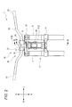
- FIG. 3 is a top view of the top bridge 50. As shown in FIG. 3, a left support hole 51 into which the upper part of the left suspension device 6 is fitted is provided on the left part of the top bridge 50. A right support hole 52 into which the upper part of the right suspension device 7 is fitted is provided in the right part of the top bridge 50.
- a rear support hole 53 into which the upper part of the steering shaft 9 is fitted is provided at the center of the top bridge 50 in the left-right direction and at the rear of the top bridge 50.
- a front support hole 54 is provided at the center of the top bridge 50 in the left-right direction and in front of the rear support hole 53.
- a spline groove is formed on the inner peripheral surface of the front support hole 54.
- the bottom bridge 14 is fixed to the lower portion of the steering shaft 9.
- the bottom bridge 14 is located below the top bridge 50 in the vertical direction of the vehicle 1.
- the bottom bridge 14 is located below the head pipe 8 in the vertical direction of the vehicle 1.
- the bottom bridge 14 extends in the left-right direction of the vehicle 1.
- the right part of the bottom bridge 14 fixes an intermediate part in the vertical direction of the right suspension device 7.
- the left portion of the bottom bridge 14 fixes an intermediate portion in the vertical direction of the left suspension device 6.
- An intermediate portion of the top bridge 50 in the left-right direction is fixed to the steering shaft 9.
- the handlebar assembly 20 is a group of parts that are directly or indirectly connected to the steering shaft 9.
- the handle bar assembly 20 includes a right grip portion 22 and a left grip portion 23.
- the right grip portion 22 is a portion that is provided on the right side of the center in the left-right direction of the vehicle 1 in an upright state and in a non-steered state and can be gripped by the rider.
- the left grip portion 23 is a portion that is provided to the left of the center in the left-right direction of the vehicle 1 in an upright state and in a non-steered state and can be gripped by the rider.
- the right grip part 22 is located on the right part
- the left grip portion 23 is located on the left side.
- the handle bar assembly 20 further includes a handle bar portion 26 and a handle bar connecting portion 21.
- the handle bar portion 26 extends in a direction along the left-right direction of the vehicle 1.
- a right grip portion 22 is provided at the right end portion of the handlebar portion 26.
- a left grip portion 23 is provided at the left end portion of the handlebar portion 26.
- the handlebar connecting portion 21 connects the handlebar portion 26 to the steering shaft 9.
- a handle bar portion 26 is fixed to the handle bar connecting portion 21.
- the handle bar connecting portion 21 connects the handle bar portion 26 to the upper portion of the steering shaft 9 and the top bridge 50.
- FIG. 4 is a cross-sectional view taken along the line IV-IV in FIG.
- the handlebar coupling portion 21 includes an upper member 40 and a lower member 30 provided below the upper member 40.
- the handle bar portion 26 is sandwiched and fixed between the upper member 40 and the lower member 30.
- the handle bar connecting portion 21 is provided above the top bridge 50.
- a lower side handle receiving portion 31 capable of accommodating the handle bar portion 26 is provided at the rear portion of the lower member 30.
- the upper member 40 is attached so as to face the lower side handle receiving portion 31.
- the upper member 40 is provided with an upper side handle receiving portion 41 at a position corresponding to the lower side handle receiving portion 31.
- the lower handle handle portion 31 and the upper handle receiver portion 41 sandwich the handle bar portion 26 so that the handle bar portion 26 is fixed to the handle bar connecting portion 21. It should be noted that, at the portion where the handlebar portion 26 is sandwiched, the boundary surface between the lower member 30 and the upper member 40 is an inclined surface that is higher than the rear portion and inclined with respect to the horizontal plane.
- the front part of the lower member 30 has a cylindrical shape having a through hole 32 penetrating in the vertical direction.
- a first bearing 16 and a second bearing 17 are provided inside the through hole 32.
- the lower member 30 is rotatably supported by the top bridge 50 via the first bearing 16.
- the inner ring 16 a of the first bearing 16 is fixed to the upper part of the top bridge 50, and the outer ring 16 b of the first bearing 16 is fixed to the lower part of the lower member 30.
- the upper part of the lower member 30 is rotatably supported on the upper part of the shaft member 12 via the second bearing 17.
- An inner ring 17 a of the second bearing 17 is fixed to the shaft member 12, and an outer ring 17 b of the second bearing 17 is fixed to the upper part of the lower member 30.
- the handle bar connecting portion 21 further includes a shaft member 12 and an outer cylinder member 13.
- the shaft member 12 and the outer cylinder member 13 are cylindrical members whose axis extends in the vertical direction.
- the shaft member 12 and the outer cylinder member 13 are provided inside the through hole 32.
- the upper end of the shaft member 12 is located above the upper end of the outer cylinder member 13.
- the lower end of the shaft member 12 is located below the lower end of the outer cylinder member 13.
- the outer cylinder member 13 is provided so as to cover a part of the outer periphery of the shaft member 12.
- the upper part of the shaft member 12 is rotatably supported by the lower member 30.
- An intermediate portion in the vertical direction of the shaft member 12 is engaged with the outer cylinder member 13.
- a lower portion of the shaft member 12 is fixed to the top bridge 50.
- the shaft member 12 is fixed to the top bridge 50 in front of the steering shaft 9.
- a plurality of spline grooves 12 a extending in the axial direction are formed on the outer peripheral surface of the lower portion of the shaft member 12.
- the upper part of the shaft member 12 protrudes upward from the upper surface of the top bridge 50.
- the lower portion of the shaft member 12 is spline-fitted into the front support hole 54 of the top bridge 50.
- the shaft member 12 is fixed so as not to rotate relative to the top bridge 50.
- the outer cylinder member 13 is a cylindrical member.
- the inner diameter of the outer cylinder member 13 is substantially equal to the outer diameter of the shaft member 12, and the outer cylinder member 13 is put on the outer peripheral surface of the shaft member 12.
- the upper part of the outer cylinder member 13 is fixed to the lower member 30.
- An intermediate portion in the vertical direction of the outer cylinder member 13 is engaged with the shaft member 12.
- the outer cylinder member 13 is not fixed to the top bridge 50.
- the outer cylinder member 13 is a metal cylindrical member that is thinner than the shaft member 12.
- the outer cylinder member 13 is more easily torsionally deformed than the shaft member 12 by the steering torque input by the rider.
- the outer cylinder member 13 is provided at the center in the left-right direction of the upright vehicle 1 (see FIG. 2).
- the outer cylinder member 13 is located in the central part. Yes.
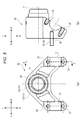
- FIG. 5 is a view showing the lower member 30 of the handlebar connecting portion 21.
- 5A is a top view of the lower member 30, and
- FIG. 5B is a bb cross-sectional view of FIG.
- a through hole 32 through which the shaft member 12 is inserted is provided in the front portion of the lower member 30.
- a second bearing 17 is provided in the through hole 32.
- the shaft member 12 is fixed to the inner ring 17a of the second bearing 17 so as not to rotate.
- the lower handle receiving portions 31 described above are provided on the left and right sides of the through-hole 32, respectively.
- a pair of first screw holes 33 are provided on the upper surface of the lower member 30.
- the pair of first screw holes 33 is provided so as to sandwich the lower handle receiving portion 31 in the front-rear direction.
- the upper member 40 is positioned with respect to the lower member 30 such that the upper side handle receiving portion 41 faces the lower side handle receiving portion 31 and screwed into the first screw hole 33, whereby the upper member 40 is Fixed to the lower member 30.
- the outer cylinder member 13 is disposed outside the shaft member 12 and inside the lower member 30.
- a spline groove 13 a is provided on the inner peripheral surface of the lower portion of the outer cylinder member 13.
- the lower part of the outer cylinder member 13 is not fixed to the lower member 30 and is splined to the outer peripheral surface of the shaft member 12.
- a spline groove 13 b is provided on the outer peripheral surface of the upper portion of the outer cylinder member 13.
- the upper part of the outer cylinder member 13 is not fixed to the shaft member 12 but is fixed to the lower member 30.
- the outer cylinder member 13 When the steering torque acts from the handlebar portion 26 and the lower member 30 rotates with respect to the shaft member 12, the outer cylinder member 13 is twisted to transmit the steering torque from the lower member 30 to the shaft member 12. That is, the steering torque input to the handlebar portion 26 is transmitted to the top bridge 50 via the outer cylinder member 13.
- the upper part of the outer cylinder member 13 When the steering torque is input, the upper part of the outer cylinder member 13 is deformed in the rotational direction around the torsion axis B extending in the axial direction of the outer cylinder member 13 with respect to the lower part.
- the upper part of the outer cylinder member 13 When the steering torque is input, the upper part of the outer cylinder member 13 is twisted around the torsion axis B extending in the axial direction of the outer cylinder member 13 with respect to the lower part.
- the twist axis B extends in the vertical direction of the vehicle 1. In the present embodiment, the twist axis B is parallel to the major axis direction of the shaft member 12.
- the steering torque is transmitted from the handlebar portion 26 to the top bridge 50 via the right auxiliary transmission member 18 and the left auxiliary transmission member 19 in addition to the outer cylinder member 13.
- a pair of left and right second screw holes 34 are provided on the lower surface of the lower member 30.
- the pair of left and right second screw holes 34 are respectively provided at positions corresponding to the left intermediate hole 55 and the right intermediate hole 56 provided in the top bridge 50.
- the left auxiliary transmission member 19 is screwed into the second screw hole 34 in the left part of the lower member 30.
- the right auxiliary transmission member 18 is screwed into the second screw hole 34 in the right part of the lower member 30.
- the top bridge 50 is provided with a left intermediate hole 55 between the left support hole 51 and the rear support hole 53 in the left-right direction, and in front of the rear support hole 53 in the front-rear direction.
- a rubber ring 57 is fitted into the inner peripheral surface of the left intermediate hole 55.
- a right intermediate hole 56 is provided between the right support hole 52 and the rear support hole 53 in the left-right direction and in front of the rear support hole 53 in the front-rear direction.
- a rubber ring 57 is fitted into the inner peripheral surface of the right intermediate hole 56.
- the left auxiliary transmission member 19 fixed to the lower member 30 passes through the left intermediate hole 55 of the top bridge 50.
- the right auxiliary transmission member 18 fixed to the lower member 30 passes through the right intermediate hole 56 of the top bridge 50.
- a rubber ring 57 is provided between the left auxiliary transmission member 19 and the inner peripheral surface of the left intermediate hole 55.
- a rubber ring 57 is provided between the right auxiliary transmission member 18 and the inner peripheral surface of the right intermediate hole 56.
- the left auxiliary transmission member 19 and the right auxiliary transmission member 18 transmit the steering torque input to the handlebar portion 26 to the top bridge 50 in an auxiliary manner.
- the rigidity required for the outer cylinder member 13 does not increase, and the increase in size of the outer cylinder member 13 is suppressed.
- the vehicle 1 includes a torque sensor 90 (an example of a steering torque detection device) that detects at least part of the steering torque input to the steering torque transmission mechanism 10. Yes.
- the torque sensor 90 is a magnetostrictive torque sensor.
- the torque sensor 90 includes a pickup coil 91.
- the pickup coil 91 is provided outside the outer cylinder member 13.
- the pickup coil 91 is fixed to the mounting substrate 92.
- the mounting board 92 is fixed to the lower member 30 of the handle bar connecting portion 21 via a bush 93.
- a line segment F indicates a steering torque transmission path.
- a steering torque is input to the handlebar portion 26
- this steering torque acts on the handlebar connecting portion 21.
- the force input to the lower member 30 is transmitted to the outer cylinder member 13 via a spline groove 13b provided in the upper part of the outer cylinder member 13. Further, this force is transmitted to the shaft member 12 through a spline groove 13 a provided in the lower portion of the outer cylinder member 13.
- the shaft member 12 transmits the steering torque to the top bridge 50 through the spline groove 12a and the front support hole 54 provided with the spline groove.
- the outer cylinder member 13 has an upper portion fixed to the lower member 30 and a lower portion fixed to the shaft member 12. For this reason, when a steering torque is input to the handlebar portion 26, the upper part of the outer cylinder member 13 is deformed in the rotational direction around the torsion axis B with respect to the lower part of the outer cylinder member 13. The upper part of the outer cylinder member 13 is twisted around the torsion axis B with respect to the lower part of the outer cylinder member 13. Therefore, the pickup coil 91 detects a change in physical quantity according to the twist amount. In the present embodiment, the pickup coil 91 detects the fluctuation of the electrical signal caused by the change in the physical quantity, that is, the twist amount of the outer cylinder member 13. This physical quantity is converted into a value indicating the steering torque by an electronic circuit electrically connected to the pickup coil 91.
- the torsional axis B of the outer cylinder member 13 of the torque sensor 90 is shifted forward from the steering axis A of the steering shaft 9 in the front-rear direction. Therefore, for example, even when the driver tries to translate the handlebar portion 26 to the left without rotating the handlebar portion 26, a force acts on the shaft member 12 from the outer cylinder member 13, The top bridge 50 rotates around the steering axis A. That is, since the outer cylinder member 13 is twisted also by the operation
- the torsional axis B of the outer cylinder member 13 is deviated from the steering axis A of the steering shaft 9, and the upper end of the steering shaft 9 is in the vertical direction of the steering shaft 9. Located above the lower end. For this reason, compared with the case where the steering shaft 9 and the shaft member 12 are arrange
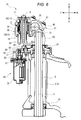
- the vehicle 1 is a cross-sectional view taken along the line VI-VI in FIG.
- the vehicle 1 includes an assist force applying mechanism 60 at the front portion of the head pipe 8.
- the torque sensor 90, the top bridge 50, and the assist force applying mechanism 60 are arranged in this order from top to bottom.
- the lower end of the pickup coil of the torque sensor 90 is located above the upper end of the top bridge 50, and the upper end of the assist force applying mechanism 60 (the upper end of the housing 85 described later in the illustrated example) is the top. It is located below the lower end of the central part of the bridge 50.
- the assist force applying mechanism 60 includes a motor 70 and a speed reducer 80. The motor torque generated by the motor 70 acts on the steering shaft 9 via the speed reducer 80.
- the motor 70 has an output shaft 71.
- the motor 70 is attached to the head pipe 8 so that the output shaft 71 is parallel to the steering axis A.
- the output shaft 71 is also parallel to the twist axis B.
- the output shaft 71 of the motor 70 is provided in front of the steering axis A of the steering shaft 9 in the front-rear direction orthogonal to the steering axis A of the steering shaft 9 in a side view of the vehicle.
- the reduction gear 80 has a first gear 82 and a second gear 83 fixed on the same intermediate shaft 81.
- the axis of the intermediate shaft 81 of the reduction gear 80, the axis of the output shaft 71 of the motor 70, and the steering axis A are parallel to each other.
- the first gear 82 of the speed reducer 80 meshes with the output shaft 71 of the motor 70.
- the second gear 83 of the speed reducer 80 meshes with a third gear 84 that is fixed to the outer peripheral surface of the steering shaft 9.
- the motor 70 and the speed reducer 80 are provided inside a common housing 85.
- the housing 85 includes a mounting portion 85a at the rear portion.
- a mounting portion 85 a of the housing 85 is sandwiched between the top bridge 50 and the head pipe 8.
- the motor torque is transmitted from the output shaft 71 to the first gear 82 of the speed reducer 80. If the 1st gearwheel 82 rotates, the 2nd gearwheel 83 will rotate with this. The rotation of the second gear 83 is transmitted to the third gear 84 of the steering shaft 9. In this way, the motor torque of the motor 70 is transmitted to the steering shaft 9.
- the steering shaft 9 is rotatably supported by an upper bearing 24 and a lower bearing 25 provided below the upper bearing 24.
- the head pipe 8 supports the steering shaft 9 via an upper bearing 24 and a lower bearing 25 so as to be rotatable.
- the outer ring of the upper bearing 24 is fixed to a housing 85 fixed to the vehicle body frame 2.
- the inner ring of the upper bearing 24 is fixed to a third gear 84 fixed to the steering shaft 9.
- the outer ring of the lower bearing 25 is fixed to the head pipe 8.
- An inner ring of the upper bearing 24 is fixed to the steering shaft 9.
- the steering torque transmission path is from the upstream side toward the downstream side, the right grip portion 22 and the left grip portion 23, the handlebar portion 26, the lower member 30, the outer cylinder member 13, the shaft member 12, and the top bridge. 50, the steering shaft 9, the bottom bridge 14, the right suspension device 7, the left suspension device 6, and the front wheel 4.
- the steering torque transmission mechanism 10 includes an outer cylinder member 13 (an example of an easy torsional deformation part) that is easily torsionally deformed by the steering torque input from the right grip part 22 or the left grip part 23.
- the outer cylinder member 13 is supported by an upper bearing 24 (an example of an upstream bearing) located on the most upstream side of the plurality of bearings 24 and 25 in the steering torque transmission path from the right grip portion 22 or the left grip portion 23 to the front wheel 4. It is provided upstream of the portion of the steering shaft 9 made.
- the outer cylinder member 13 is easier to twist than the shaft member 12 when a steering force is input from the rider to the right grip portion 22 or the left grip portion 23.
- the outer cylinder member 13 is easier to twist than the lower member 30 and the handlebar portion 26 when a steering force is input from the rider to the right grip portion 22 or the left grip portion 23.
- the outer cylinder member 13 is more than the top bridge 50, the steering shaft 9, the bottom bridge 14, the right suspension device 7, and the left suspension device 6 when a steering force is input from the rider to the right grip portion 22 or the left grip portion 23. Easy to twist and deform.
- the torque sensor 90 can easily detect at least part of the steering torque input from the right grip portion 22 or the left grip portion 23 with high accuracy.
- the leaning vehicle described in Patent Document 1 has a steering shaft that transmits the steering torque input from the right grip and the left grip to the front wheels.
- the handle bar provided with the right grip portion and the left grip portion is provided at the upper portion of the vehicle.
- the front wheels are provided at the lower part of the vehicle. For this reason, the steering shaft extends in the vertical direction of the body frame.
- the steering torque sensor detects the amount of twist generated in the steering shaft.
- the steering shaft is provided with a torsional deformation easy portion that is lower in rigidity than other portions and is easily torsionally deformed.
- the steering torque sensor detects the deformation amount of the torsional deformation easy portion.
- the steering torque sensor is configured to monitor a portion having high rigidity and is difficult to torsionally deform, it is difficult to accurately detect the steering torque.
- the parts with low rigidity are greatly twisted, and the parts with high rigidity monitored by the steering torque sensor are difficult to torsionally deform, and steering torque can be accurately applied. Difficult to detect. For this reason, the leaning vehicle of Patent Document 1 can detect the steering torque with high accuracy.
- the steering shaft of the leaning vehicle of Patent Document 1 is rotatably supported on the head pipe by a plurality of bearings. Unlike the leaning vehicle disclosed in Patent Document 1, when a steering shaft is supported by a single bearing, a large force acting on the bearing acts, and a large bearing that can withstand the force is required. It is.
- the leaning vehicle disclosed in Patent Document 1 accurately detects the steering torque while ensuring the necessary rigidity.
- the present inventor has found that, in a vehicle configured as in Patent Document 1, considering the bending force acting on the steering shaft, the support rigidity for supporting the steering shaft tends to be insufficient as follows. It was.
- bending force acts on the steering shaft.
- a bending force acts on the steering shaft.
- a force in the front-rear direction acts on the lower portion of the steering shaft, so that the lower portion of the steering shaft is largely displaced as compared with the portion above it.
- a bending force is applied to the steering shaft provided with the torsional deformation easy part, the bending is easy at the torsional deformation easy part, but the portion above the torsional deformation easy part is not greatly deformed.
- a configuration in which the steering shaft is rotatably supported by an upper bearing and a lower bearing provided below the upper bearing will be described as an example. It is assumed that a bending force acts on the lower part of such a steering shaft.
- the torsional deformation easy part for detecting the steering torque is provided below the lower bearing, the bending force is concentrated on the torsional deformation easy part, and the torsional deformation easy part is greatly deformed. Therefore, it is conceivable to secure rigidity by increasing the diameter of the torsionally deformable portion in an attempt to ensure rigidity against bending force at the torsionally deformable portion.
- the lower bearing is increased in size, or in order to increase the rigidity of the torsionally deformable portion, the portion of the other steering shaft is increased in size and the steering shaft is increased in size.
- the steering torque transmission mechanism 10 of the vehicle 1 includes an outer cylindrical member 13 (an example of an easy torsion deformable portion) that is easily torsionally deformed by the steering torque input from the right grip portion 22 or the left grip portion 23. It is out.
- the outer cylinder member 13 is used as an upper bearing 24 (an example of an upstream bearing) located on the most upstream side of the plurality of bearings 24 and 25 in the steering torque transmission path from the right grip part 22 or the left grip part 23 to the front wheel 4. It is provided upstream of the portion of the steering shaft 9 that is supported.
- the outer cylinder member 13 as a torsional deformable portion that easily twists and deforms with respect to the steering torque is provided on the handlebar assembly 20. Since at least one of the plurality of parts constituting the handlebar assembly 20 can be used to form the torsional deformable part, the degree of freedom in designing the easy torsional deformable part is high.
- the handlebar assembly 20 includes a handlebar portion 26 and a handlebar connecting portion 21 that connects the handlebar portion 26 to the steering shaft 9.
- the outer cylinder member 13 as the torsional deformation easy portion is provided on the handlebar connecting portion 21.
- the torque sensor 90 is provided in the handlebar assembly 20. Since the torque sensor can be mounted using at least one of a plurality of parts constituting the handlebar assembly 20, the degree of freedom in arranging the torque sensor is high.
- the handlebar assembly 20 includes a handlebar portion 26 and a handlebar connecting portion 21 that connects the handlebar portion 26 to the steering shaft 9.
- the torque sensor 90 is provided on the handlebar connecting portion 21.
- the vehicle 1 includes a motor 70 that can input an auxiliary steering torque to the steering torque transmission mechanism 10.
- the motor 70 can assist the rider in steering.
- the motor 70 is a steering shaft that is supported by the upper bearing 24 located on the most upstream side of the plurality of bearings 24 and 25 in the steering torque transmission path from the handlebar assembly 20 to the front wheel 4.
- the auxiliary steering torque is input downstream from the portion 9. Since torque by the motor 70 is applied to the downstream side of the outer cylinder member 13, it is easy to detect the steering torque with high accuracy by the torque sensor 90 that detects the torque sensor based on the torsional deformation of the outer cylinder member 13.
- the output of the torque sensor 90 current can be supplied to the motor 70 to generate motor torque to assist the driver's steering.
- the output of the torque sensor 90 is used for assisting the steering torque.
- the present invention is not limited to this.
- the output of the torque sensor 90 may be used for traction control, or the output of the torque sensor 90 may be used to control ABS (Anti-lock Brake System).
- At least a part of the torque sensor 90 is at the right side of the left suspension device 6 and to the left of the right suspension device 7 in the left-right direction in a front view of the vehicle in an upright and non-steered state. Is located. In the present embodiment, the entire torque sensor 90 is positioned to the right of the left suspension device 6 and to the left of the right suspension device 7 in a front view of the upright and non-steered vehicle.
- the top bridge 50 connects the steering shaft 9 and the left and right suspension devices 6 and 7, so that the steering torque input to the handlebar portion 26 is applied to the steering shaft 9. There is no concentration. For this reason, it is not necessary to enlarge the diameter of the steering shaft 9, and the enlargement of the vehicle can be suppressed.
- the torque sensor 90 detects the steering torque input to the handlebar portion 26 based on the amount of twist (an example of a change in physical quantity) of the outer cylinder member 13 due to the relative displacement of the lower member 30 and the shaft member 12. That is, the torque sensor 90 detects a change in the physical quantity of the outer cylinder member 13 located on the upstream side of the top bridge 50 in the steering torque transmission path transmitted from the handlebar portion 26 to the front wheel 4.
- the torque sensor 90 detects a change in the physical quantity of the outer cylinder member 13 located on the upstream side of the top bridge 50 in the route. For this reason, the torque sensor 90 can accurately detect the steering torque input to the handlebar portion 26.
- the torque sensor 90 is in the right direction and the right suspension device 7 in the left-right direction from the left suspension device 6 in a front view of the upright and non-steered vehicle. Located to the left. For this reason, the torque sensor 90 can be disposed near the steering shaft 9.
- the handle bar connecting part 21 provided with the torque sensor 90 also moves together with the handle bar part 26.
- the torque sensor 90 is disposed at a position far from the steering shaft 9, the other member is positioned far from the steering shaft 9 so that the torque sensor 90 does not interfere with the other member. Therefore, the vehicle becomes larger.
- the torque sensor 90 since the torque sensor 90 can be disposed near the steering shaft 9, the torque sensor 90 is unlikely to interfere with other members, and the size of the vehicle 1 can be suppressed.
- the torque sensor 90 When the handlebar part 26 is rotated, the torque sensor 90 also moves with the handlebar part 26. On the other hand, the head pipe 8 does not move together with the handlebar portion 26 even if the handlebar portion 26 is rotated. For this reason, if the handlebar part 26 is rotated, the torque sensor 90 and the head pipe 8 may interfere with each other. For this reason, in order to avoid the interference of the torque sensor 90 and the head pipe 8, there is a possibility that a restriction on the degree of freedom in designing the vehicle occurs.
- At least a part of the torque sensor 90 is from the lower end of the top bridge 50 positioned above the head pipe 8 in a front view of the upright and non-steered vehicle. Is also located above. For this reason, even if the handlebar portion 26 rotates, the torque sensors 90 are not easily interfered with the top bridge 50 because they are provided at positions separated from each other in the vertical direction, and the degree of freedom in designing the vehicle is high.
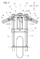
- FIG. 7 is a schematic view of the vehicle 100 according to the second embodiment of the present invention as viewed from the front.
- the torsional deformation easy portion is provided in the handlebar portion.
- the vehicle 100 includes a steering torque transmission mechanism 101, a vehicle body frame 102 including a head pipe 109, and a front wheel 103.
- the steering torque transmission mechanism 101 transmits the steering torque input from the driver to the front wheels 103.
- the steering torque transmission mechanism 101 includes a steering shaft 108, a handlebar assembly 130, and a front wheel connecting portion 140.
- the steering torque transmission mechanism 101 mechanically transmits the steering torque input to the handlebar assembly 130 to the front wheels 103.
- the handlebar assembly 130 is a group of parts connected directly or indirectly to the steering shaft 108.
- the handle bar assembly 130 includes a right grip part 104, a right handle bar part 106, and a right connection part 114.
- the handle bar assembly 130 includes a left grip part 105, a left handle bar part 107, and a left connecting part 115.
- the front wheel connecting part 140 connects the steering shaft 108 and the front wheel 103.
- the front wheel connecting portion 140 includes a top bridge 110, a bottom bridge 111, a right suspension device 112, and a left suspension device 113.
- the right grip portion 104 is provided on the right portion of the right handlebar portion 106.
- the left part of the right handlebar part 106 is connected to the upper part of the right suspension device 112.
- a right connecting portion 114 is provided on the left portion of the right handlebar portion 106.
- the right handlebar portion 106 is coupled to the right suspension device 112 via the right coupling portion 114.
- FIG. 8 is an enlarged view showing the right handlebar portion 106 and the right connecting portion 114.
- a part of the connection portion between the right handlebar portion 106 and the right connection portion 114 is shown in cross section.
- the left part of the right handlebar part 106 and the right part of the right connecting part 114 are connected via a right intermediate shaft part 123 (an example of a torsional deformation easy part).
- a lower portion of the right intermediate shaft portion 123 is fixed to the right handlebar portion 106 so as not to rotate.
- the upper portion of the right intermediate shaft portion 123 is fixed to the right connecting portion 114 so as not to rotate.
- the right intermediate shaft portion 123 extends in the direction of the right twist axis B1.
- the right twist axis B1 of the right intermediate shaft portion 123 extends in a direction orthogonal to the direction in which the right handlebar portion 106 extends.
- the right handlebar portion 106 can be displaced about the right twist axis B1 with respect to the right coupling portion 114.
- FIG. 7 when the vehicle 100 is divided into a right part, a center part, and a left part in the left-right direction of the vehicle 100 in a front view of the vehicle 100 in an upright state, the right intermediate shaft part 123 is placed on the right part. Is located.
- the right torque sensor 150 is provided on the outer periphery of the right intermediate shaft portion 123.
- the right torque sensor 150 is a magnetostrictive torque sensor.
- the right torque sensor 150 includes a pickup coil 151 and a housing 152 that houses the pickup coil 151.
- the housing 152 is fixed to the right connecting portion 114.
- the pickup coil 151 is provided so as to face the right intermediate shaft portion 123.
- the pickup coil 151 is configured to be able to detect fluctuations in the electrical signal in accordance with the torsional deformation around the right torsion axis B1 of the right intermediate shaft portion 123.
- the right torque sensor 150 is configured to detect the steering torque input from the right grip portion 104 based on the torsional deformation of the right intermediate shaft portion 123.
- the right torque sensor 150 is configured to be able to detect at least a part of the steering torque input to the steering torque transmission mechanism 101 based on the torsional deformation of the right intermediate shaft portion 123.
- the left grip portion 105 is provided on the left portion of the left handlebar portion 107.
- a right portion of the left handlebar portion 107 is connected to an upper portion of the left suspension device 113.
- a left connecting portion 115 is provided on the right portion of the left handlebar portion 107.
- the left handlebar portion 107 is connected to the left suspension device 113 via the left connecting portion 115.
- the right part of the left handlebar part 107 and the left part of the left connecting part 115 are connected via a left intermediate shaft part 124 (an example of a torsional deformable part).
- a lower portion of the left intermediate shaft portion 124 is fixed to the left handlebar portion 107 so as not to rotate.
- the upper part of the left intermediate shaft part 124 is fixed to the left connecting part 115 so as not to rotate.
- the left intermediate shaft portion 124 extends in the direction of the left twist axis B2.
- the left twist axis B2 of the left intermediate shaft portion 124 extends in a direction orthogonal to the direction in which the left handlebar portion 107 extends.
- the left handlebar portion 107 can be displaced about the left twist axis B ⁇ b> 2 with respect to the left connecting portion 115.
- the left intermediate shaft part 124 is located on the left part. ing.
- a left torque sensor 160 is provided on the outer periphery of the left intermediate shaft portion 124.
- the configuration of the left torque sensor 160 is the same as that of the right torque sensor 150.
- the left torque sensor 160 is configured to detect the steering torque input from the left grip portion 105 based on the torsional deformation of the left intermediate shaft portion 124 around the left torsion axis.
- the left torque sensor 160 is configured to be able to detect at least part of the steering torque input to the steering torque transmission mechanism 101 based on the torsional deformation of the left intermediate shaft portion 124 around the left torsion axis.
- the upper part of the right suspension device 112 is fixed to the right part of the top bridge 110.
- the upper portion of the right suspension device 112 is connected to the right handlebar portion 106 below the top bridge 110.
- An intermediate portion in the vertical direction of the right suspension device 112 is fixed to the bottom bridge 111.
- the lower part of the right suspension device 112 supports the front wheel 103 rotatably.
- the upper part of the left suspension device 113 is fixed to the left part of the top bridge 110.
- the upper part of the left suspension device 113 is connected to the left handlebar portion 107 below the top bridge 110.
- An intermediate portion in the vertical direction of the left suspension device 113 is fixed to the bottom bridge 111.
- the lower part of the left suspension device 113 supports the front wheel 103 rotatably.
- the top bridge 110 is connected to the upper portion of the right suspension device 112, the upper portion of the left suspension device 113, and the upper portion of the steering shaft 108.
- the upper portion of the right suspension device 112, the upper portion of the left suspension device 113, and the upper portion of the steering shaft 108 are not relatively displaceable by the top bridge 110.
- the right portion of the top bridge 110 is connected to the right suspension device 112 above the right connection portion 114.
- the left portion of the top bridge 110 is connected to the left suspension device 113 above the left connecting portion 115.
- a central portion of the top bridge 110 is fixed to an upper portion of the steering shaft 108.
- the bottom bridge 111 is connected to an intermediate portion of the right suspension device 112, an intermediate portion of the left suspension device 113, and a lower portion of the steering shaft 108.
- the intermediate portion of the right suspension device 112, the intermediate portion of the left suspension device 113, and the lower portion of the steering shaft 108 cannot be relatively displaced by the bottom bridge 111.
- the bottom bridge 111 is connected to the right suspension device 112 and the left suspension device 113 below the top bridge 110.
- the bottom bridge 111 is fixed to the lower end portion of the steering shaft 108.
- the steering shaft 108 is rotatably supported by the head pipe 109.
- the head pipe 109 is fixed to the vehicle body frame 102.
- the head pipe 109 is located below the top bridge 110 and above the bottom bridge 111.
- the upper end of the steering shaft 108 is located above the upper end of the head pipe 109.
- the lower end of the steering shaft 108 is located below the lower end of the head pipe 109.
- the steering shaft 108 is fixed to the top bridge 110 and the bottom bridge 111.
- an upper bearing 116 and a lower bearing 117 positioned below the upper bearing 116 are provided in the head pipe 109.
- the upper bearing 116 and the lower bearing 117 support the steering shaft 108 so as to be rotatable with respect to the head pipe 109.
- the front wheel 103 is steered leftward. That is, when viewed from above, the steering shaft 108 rotates counterclockwise around the head pipe 109.
- the steering force input to the right grip portion 104 by the driver is transmitted to the right handlebar portion 106.
- the steering torque input to the right handlebar portion 106 is transmitted to the right connecting portion 114 via the right intermediate shaft portion 123.
- the lower portion of the right intermediate shaft portion 123 fixed to the right handlebar portion 106 is rotated about the right twist axis B1 with respect to the upper portion fixed to the right connecting portion 114. Displaces in the direction of rotation.
- the steering torque is input to the right handlebar portion 106, the lower portion of the right intermediate shaft portion 123 is twisted about the right twist axis B1 with respect to the upper portion.
- the steering torque input to the right connecting portion 114 is transmitted from the upper portion of the right suspension device 112 through the top bridge 110, the steering shaft 108, the bottom bridge 111, the middle portion of the right suspension device 112, and the lower portion of the right suspension device 112 to the front wheels. 103.
- the steering force input to the left grip portion 105 by the driver is transmitted to the left handlebar portion 107.
- the steering torque input to the left handlebar portion 107 is transmitted to the left connecting portion 115 via the left intermediate shaft portion 124.
- the left intermediate shaft portion 124 is twisted about the left twist axis B2.
- the steering torque input to the left connecting portion 115 is transmitted from the upper portion of the left suspension device 113 through the top bridge 110, the steering shaft 108, the bottom bridge 111, the intermediate portion of the left suspension device 113, and the lower portion of the left suspension device 113 to the front wheels. 103.
- the transmission path of the steering torque input from the driver's right hand is from the upstream side toward the downstream side, the right grip portion 104, the right handlebar portion 106, the right intermediate shaft portion 123, the right connection.
- the part 114, the upper part of the right suspension unit 112, the top bridge 110, the steering shaft 108, the bottom bridge 111, and the lower part of the right suspension unit 112 are arranged in this order.
- the transmission path of the steering torque input from the driver's left hand is from the upstream side toward the downstream side, the left grip portion 105, the left handlebar portion 107, the left intermediate shaft portion 124, the left connecting portion 115, the left
- the upper part of the suspension device 113, the top bridge 110, the steering shaft 108, the bottom bridge 111, and the lower part of the left suspension device 113 are arranged in this order.
- the most upstream bearing is the upper bearing 116.
- a part of the steering torque input to the right connecting portion 114 is transmitted from the intermediate portion of the right suspension device 112 to the front wheel 103 via the lower portion of the right suspension device 112.
- a part of the steering torque input to the left connecting portion 115 is transmitted from the intermediate portion of the left suspension device 113 to the front wheel 103 via the lower portion of the left suspension device 113.
- the right intermediate shaft portion 123 and the left intermediate shaft portion 124 are provided as the torsional deformation easy portions that are easily torsionally deformed by the steering torque input from the right grip portion 104 and the left grip portion 105 by the rider.
- the right intermediate shaft portion 123 provided on the left portion of the right handlebar portion 106 is provided on the left side of the right grip portion 104.
- the right intermediate shaft portion 123 is provided on the right side with respect to the center in the left-right direction of the vehicle 1 in an upright state and a non-steered state.
- the left intermediate shaft portion 124 provided on the right portion of the left handlebar portion 107 is provided on the left side of the left grip portion 105.
- the left intermediate shaft portion 124 is provided on the left side with respect to the center in the left-right direction of the vehicle 1 in an upright state and a non-steered state.
- the right intermediate shaft portion 123 and the left intermediate shaft portion 124 are provided symmetrically with respect to the center in the left-right direction of the vehicle 1.
- the vehicle 100 is steered based on the right torque sensor 150 that detects at least part of the steering torque input to the steering torque transmission mechanism based on the torsional deformation of the right intermediate shaft part 123 and the torsional deformation of the left intermediate shaft part 124. And a left torque sensor 160 for detecting at least part of the steering torque input to the torque transmission mechanism.
- the right intermediate shaft portion 123 and the left intermediate shaft portion 124 are portions having the lowest rigidity in the entire steering torque transmission mechanism 101.
- the steering shaft 108 is supported by the upper bearing 116 and the lower bearing 117.
- the uppermost bearing is the upper bearing 116.
- Both the right intermediate shaft portion 123 and the left intermediate shaft portion 124 are provided on the upstream side of the upper bearing 116 positioned on the most upstream side in the steering torque transmission path.
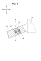
- FIG. 9 is a schematic view of the vehicle 200 according to the third embodiment of the present invention viewed from the front.
- the torsional deformation easy portion 218 is provided on the steering shaft 208.
- the vehicle 200 includes a steering torque transmission mechanism 201, a body frame 202 including a head pipe 209, and a front wheel 203.
- the steering torque transmission mechanism 201 transmits the steering torque input from the driver to the front wheels 203.
- the steering torque transmission mechanism 201 includes a steering shaft 208, a handlebar assembly 230, and a front wheel connecting portion 240.
- the steering torque transmission mechanism 201 mechanically transmits the steering torque input to the handlebar assembly 230 to the front wheels 203.
- the handlebar assembly 230 is a group of parts connected directly or indirectly to the steering shaft 208.
- the handle bar assembly 230 includes a right grip part 204, a left grip part 205, and a handle bar part 206.
- the front wheel connecting portion 240 includes a bottom bridge 211, a right suspension device 212, and a left suspension device 213.
- the handlebar part 206 is fixed to the upper part of the steering shaft 208.
- a right grip portion 204 is provided on the right portion of the handlebar portion 206.
- a left grip portion 205 is provided on the left portion of the handlebar portion 206.
- An intermediate portion in the left-right direction of the handle bar portion 206 is fixed to the steering shaft 208.
- the steering shaft 208 is rotatably supported by the head pipe 209.
- the head pipe 209 is fixed to the vehicle body frame 202.
- the head pipe 209 is located above the bottom bridge 211.
- the upper end of the steering shaft 208 is located above the upper end of the head pipe 209.
- the lower end of the steering shaft 208 is located below the lower end of the head pipe 209.
- a lower portion of the steering shaft 208 is fixed to the bottom bridge 211.
- the head pipe 209 is provided with an upper bearing 216 and a lower bearing 217 positioned below the upper bearing 216.
- the upper bearing 216 and the lower bearing 217 support the steering shaft 208 so as to be rotatable with respect to the head pipe 209.
- the right part of the bottom bridge 211 is fixed to the upper part of the right suspension device 212.
- the left part of the bottom bridge 211 is fixed to the upper part of the left suspension device 213.
- An intermediate portion in the left-right direction of the bottom bridge 211 is fixed to a lower portion of the steering shaft 208.
- the upper portion of the right suspension device 212, the upper portion of the left suspension device 213, and the lower portion of the steering shaft 208 cannot be relatively displaced by the bottom bridge 211.
- a lower portion of the right suspension device 212 and a lower portion of the left suspension device 213 support the front wheel 203 in a rotatable manner.
- the handlebar portion 206 is counterclockwise as viewed from above. It turns around and the front wheel 203 is steered to the left. That is, when viewed from above, the steering shaft 208 rotates counterclockwise around the head pipe 209.
- the steering force input by the driver to the right grip portion 204 and the left grip portion 205 is transmitted to the right suspension device 212 and the left suspension device 213 via the handlebar portion 206, the steering shaft 208, and the bottom bridge 211, and is transmitted to the front wheels 203. Steer.
- the steering torque transmission path is from the upstream side toward the downstream side, the right grip portion 204, the left grip portion 205, the handlebar portion 206, the steering shaft 208, the bottom bridge 211, the right suspension device 212, The left suspension device 213 and the front wheel 203 are in this order.
- the upper bearing 216 and the lower bearing 217 that support the steering shaft 208 the uppermost bearing in the steering torque transmission path is the upper bearing 216.
- the torsional deformation easy portion 218 is provided on the upper portion of the steering shaft 208.
- the torsional deformation easy portion 218 can be deformed in the rotation direction around the torsion axis B.
- the torsional deformation easy portion 218 can be torsionally deformed about the torsion axis B.
- the torsion axis B is coaxial with the steering axis A of the steering shaft 208.
- the upper part of the torsional deformation easy part 218 is fixed to the handlebar part 206.
- the lower part of the torsional deformation easy part 218 is supported by the upper bearing 216.
- the driver displaces the right grip portion 204 and the left grip portion 205 and the handlebar portion 206 rotates, the torsional deformation easy portion 218 is twisted.
- the torsional deformation easy portion 218 is located at the center when the vehicle 200 is divided into three parts, a right portion, a center portion, and a left portion, in a front view of the upright and non-steered vehicle 200.
- the torsional deformation easy portion 218 is a portion having the lowest rigidity and easy to twist in the entire steering shaft 208.
- the easy torsional deformation portion 218 can be provided as a portion having the smallest diameter in the steering shaft 208 or a portion having a rectangular cross section that tends to be less rigid than a circular cross section.
- the torsional deformation easy part 218 is more likely to be twisted and deformed by the steering torque than the handlebar part 206, the bottom bridge 211, the right suspension device 212, and the left suspension device 213 that constitute the transmission path of the steering torque.
- the vehicle 200 includes a steering torque detection device 220 that detects a change in physical quantity based on the torsional deformation of the torsional deformation easy portion 218.
- the steering torque detection device 220 can detect the amount of twist of the torsional deformation easy portion 218.
- the steering torque detection device 220 is a magnetostrictive sensor having a sensor coil.
- the steering torque detection device 220 is provided so as to face the torsional deformation easy portion 218.
- a cylindrical housing 221 to which the sensor coil is fixed is provided so as to face the torsional deformation easy portion 218.
- the housing 221 is provided above the head pipe 209.
- the housing 221 is provided below the handle bar portion 206.
- the housing 221 is fixed to the vehicle body frame 202.
- the housing 221 is provided above the upper bearing 216.
- the steering shaft 208 is supported by an upper bearing 216 and a lower bearing 217.
- the uppermost bearing is the upper bearing 216.
- the torsional deformation easy portion 218 is provided on the upstream side of the upper bearing 216 located on the most upstream side in the steering torque transmission path.
- the steering torque detection device 220 is provided on the head pipe 209 that is a part of the vehicle body frame 202.
- the torsional deformation easy portion 218 is relatively displaced with respect to the vehicle body frame 202. Therefore, it is easy to ensure a large change amount of the torsional deformation easy portion 218 as viewed from the vehicle body frame 202, and the steering torque detection device 220 can easily detect a change in physical quantity based on the torsional deformation of the easy torsion deformation portion 218.
- the body frame 202 is configured with relatively high rigidity, the steering torque detection device 220 can be easily fixed with high support rigidity. For this reason, it is easy to detect the steering torque with high accuracy.
- the present invention can be applied to a leaning vehicle such as a four-wheel vehicle having a front wheel and two rear wheels.
- the present invention can also be applied to a vehicle including a parallelogram type link mechanism that supports a right front wheel and a left front wheel so that the vehicle body frame can be displaced in the vertical direction of the vehicle.
- the front wheel connecting portion that connects the steering shaft and the front wheel includes a pitman arm that is fixed to the steering shaft and rotates together with the steering shaft, and a tie rod that connects the pitman arm to the right front wheel and the left front wheel.
- the present invention can also be applied to a vehicle including a double wishbone type link mechanism that supports a right front wheel and a left front wheel so that the vehicle body frame can be displaced in the vertical direction of the vehicle.
- the front wheel connecting portion that connects the steering shaft and the front wheel includes a pitman arm that is fixed to the steering shaft and rotates together with the steering shaft, and a tie rod that connects the pitman arm to the right front wheel and the left front wheel. Applicable.
- the entire torque sensor 90 is positioned to the right of the left suspension device 6 and to the left of the right suspension device 7 in the front view of the upright and non-steered vehicle, and the head
- this invention is not limited to this.
- At least a part of the torque sensor is positioned to the right of the left suspension device and to the left of the right suspension device in the left-right direction, and above the head pipe, in the left-right direction, as viewed from the front of the vehicle in an upright and non-steered state What is necessary is just to be located above the lower end of the top bridge.
- the vehicle 1 including the straight bar type handlebar portion 26 has been described.
- the present invention is not limited to this.
- a handle having a bent shape, a handle having a shape divided at the center in the left-right direction, and the like can be employed.
- the torsional deformation of the present invention is a deformation accompanied by displacement in the circumferential direction of the axis when torque around the axis is input.
- the torsional deformation of the present invention is a deformation accompanied by a displacement in the circumferential direction of the axis due to the steering torque input from the right grip portion or the left grip portion.
- This axis is an axis of torsional deformation and can be rephrased as a torsion axis.
- the torsional deformation of the present invention includes (A) elastic deformation in the circumferential direction of a part of the axis of one component.
- the elastic deformation in the circumferential direction of the axis is a deformation accompanied by displacement in the circumferential direction of the axis.
- the elastic deformation in the circumferential direction of the axis with respect to the steering torque can be adjusted by adjusting the relationship between the rigidity of a part of one component and the rigidity of another part.
- the torsional deformation of the present invention may include (B) a deformation in which the two parts cause a relative positional shift in the circumferential direction of the axis.
- an elastic body such as a spring in the circumferential direction of the axis between the two parts, it is possible to adjust the relative positional deviation in the circumferential direction of the axis with respect to the steering torque.
- (A) torsional deformation in which a part of one component is elastically deformed in the circumferential direction of the axis is more preferable.
- the steering torque detector described in the first to third embodiments described above detects the steering torque based on the torsional deformation of (A). Therefore, the first embodiment to the third embodiment described above are more preferable embodiments.
- the magnetostrictive torque sensor 90 has been described in the first embodiment, the second embodiment, and the third embodiment, the present invention is not limited to this.
- a change in physical quantity based on the relative displacement between the lower member 30 and the shaft member 12 such as a strain sensor that can detect the strain of the outer cylinder member 13 or an encoder that can detect the relative rotation amount of the lower member 30 and the shaft member 12.
- the torque sensor described in International Publication No. 2014/042267 can be adopted as the steering torque detection device of the present invention.
- the torque sensor detects the steering torque based on the torsional deformation of (B) described above.
- a sensor attached part to which the torque sensor is attached is one part constituting the steering torque transmission path.
- the sensor attached part has an upstream part and a downstream part that can rotate around the torsion axis, and a connecting coil spring that connects the upstream part and the downstream part.
- One end of the coupling coil spring is fixed to the upstream part, and the other end is fixed to the downstream part.
- the connecting coil spring is configured to transmit the rotational torque of the upstream part to the downstream part.
- the torque sensor is attached to the sensor attached component.
- the torque sensor includes a ring-shaped permanent magnet attached to one of the upstream part or the downstream part, an induction ring attached to the other of the upstream part or the downstream part, and a magnetic detection unit.
- the ring-shaped permanent magnet and the induction ring are arranged coaxially with the twist axis.
- the ring-shaped permanent magnets are arranged in such a manner that the magnetic poles magnetized in the twist axis direction are alternately reversed in the circumferential direction.
- Each of the magnetic poles has a certain width in the circumferential direction.
- the guide ring has a plurality of protrusions and a ring body.
- Each protrusion has a circumferential width.
- the circumferential width of at least one protrusion is smaller than the circumferential width of at least one magnetic pole of the permanent magnet.
- the ring body is provided coaxially with the twist axis.
- the strength of magnetization changes according to the position of the protrusion with respect to the position of the magnetic pole of the permanent magnet.
- the magnetic detection unit detects the magnetic flux of the ring body.
- the magnetization intensity of the ring body changes according to the amount of displacement.
- the magnetic detection unit detects the magnetic flux of the ring body, and outputs an electrical signal corresponding to the amount of shift in the rotational direction around the torsion axis with respect to the downstream part of the upstream part. That is, the magnetism detection unit can detect at least a part of the steering torque input to the steering torque transmission mechanism based on the torsional deformation of the upstream part with respect to the downstream part.
- the rotation axis A is along the vertical direction of the vehicle 1” means that the angle at which the rotation axis A intersects with the vertical direction of the vehicle 1 is 45 in addition to the rotation axis A being parallel to the vertical direction of the vehicle 1 Also includes cases of less than degrees.
- this invention may take the following structures.
- a straddle-type vehicle that can turn by tilting the body frame, The vehicle body frame; Front wheels, In the upright state of the vehicle, a left suspension device that is provided to the left of the front wheel and rotatably supports the front wheel; In the upright state of the vehicle, a right suspension device provided to the right of the front wheels and rotatably supporting the front wheels; A head pipe connected to the body frame; A steering shaft rotatably supported by the head pipe; A top bridge that connects the upper portion of the left suspension device, the upper portion of the right suspension device, and the upper portion of the steering shaft to each other so as not to rotate; A handle to which the steering torque of the driver is input; A transmission member for transmitting a steering torque input to the steering wheel to the top bridge; A sensor capable of detecting a steering torque input to the steering wheel, The transmission member is A first part provided on the handle or a member that rotates as the handle rotates; A second bridge is provided on the top bridge or a member that rotates as the
- the sensor is input to the handle by detecting a change in a physical quantity based on a relative displacement between the first part and the second part of the transmission member that transmits the steering torque input to the handle to the top bridge.
- the steering torque At least a part of the sensor is positioned to the right of the left suspension device, to the left of the right suspension device, and above the head pipe in a front view of an upright and non-steered vehicle.
- a straddle-type vehicle located above the lower end of the top bridge.
- the output shaft of the motor is provided in front of the rotation shaft of the steering shaft in the front-rear direction orthogonal to the rotation shaft of the steering shaft in a side view of the vehicle.
- the assist force applying mechanism has a housing in which the motor and the speed reducer are provided. At least a part of the housing is sandwiched and fixed between the top bridge and the head pipe.
- the speed reducer has at least one gear;
- the rotating shaft of the steering shaft, the rotating shaft of the motor, and the rotating shaft of the gear of the speed reducer are parallel to each other.
- One of the first part and the second part is a shaft member, and the other of the first part and the second part is a cylinder that is inserted through the shaft member and is rotatable around the shaft member.
- a section, A central axis of the shaft member is deviated from a rotation axis of the steering shaft; The upper end of the steering shaft is located above the lower end of the shaft member in the vertical direction of the steering shaft.
- the sensor is A metal tubular detection object, wherein the shaft member is inserted, one end in the axial direction is fixed to the shaft member, and the other end in the axial direction is fixed to the tubular portion;
- a pickup coil provided on an outer periphery of the cylindrical portion and capable of detecting torsion of the detected body.
- a leaning vehicle having a steering torque sensor, having a high support rigidity against bending and suppressing an increase in size.
Landscapes
- Engineering & Computer Science (AREA)
- Mechanical Engineering (AREA)
- Steering Devices For Bicycles And Motorcycles (AREA)
Abstract
本発明は、操舵トルクセンサを有し、曲げに対する支持剛性が高く大型化が抑制されたリーニング車両を提供する。 リーニング車両(1)は、ヘッドパイプ(8)を含む車体フレーム(2)、前輪(4)、複数の軸受(24,25)で支持されたステアリングシャフト(9)、ハンドルバーアセンブリ(20)、前輪連結部(11)を有し、操舵トルクを伝達する操舵トルク伝達機構(10)、操舵トルク検出装置(90)と、を備える。操舵トルク伝達機構(10)は、操舵トルク伝達経路において、複数の軸受(24,25)のうち最も上流に位置する上流軸受(24)に支持されたステアリングシャフト(9)の部位より上流に設けられ、グリップ部(22,23)から入力された操舵トルクによってねじれ変形しやすいねじれ変形容易部(13)を含む。操舵トルク検出装置(90)は、ねじれ変形容易部(13)のねじれ変形に基づいて操舵トルク伝達機構(10)に入力された操舵トルクの少なくとも一部を検出する。
Description
本発明は、車両の左右方向の中央に設けられたヘッドパイプを含み、車両の右旋回時に車両の左右方向の右方向へ傾斜し、車両の左旋回時に車両の左右方向の左方向へ傾斜する車体フレームを有するリーニング車両に関する。
特許文献1は、車両の左右方向の中央に設けられたヘッドパイプを含み、車両の右旋回時に車両の左右方向の右方向へ傾斜し、車両の左旋回時に車両の左右方向の左方向へ傾斜する車体フレームを有するリーニング車両を開示する。特許文献1に記載のリーニング車両は、パワーアシストステアリング装置(EPS)と、操舵トルクを検出する操舵トルクセンサと、を有している。このリーニング車両は、操舵トルクを伝達する経路の上流側から下流側に向かって、例えば、右グリップ部と左グリップ部が設けられたハンドルバー、ハンドルバーが固定されたステアリングシャフト、前輪が支持されるサスペンションといった部材から構成される操舵トルク伝達経路を有している。
運転者がグリップ部に操舵力を入力すると、操舵トルクが、操舵トルク伝達経路を介して前輪に伝達される。操舵トルク伝達経路を構成する部材がねじられながら、該操舵トルクは前輪に伝達される。特許文献1に記載のリーニング車両において、操舵トルクに応じて生じるねじりを検出する操舵トルクセンサが操舵トルク伝達経路の途中に設けられている。このような構成により、特許文献1に記載のリーニング車両は、操舵トルクを検出し、検出された操舵トルクに応じてEPSを制御している。
本発明者は、特許文献1に記載のリーニング車両では、ステアリングシャフトを支持する剛性が不足しがちであることを見出した。ステアリングシャフトを支持する部材を単に大型化すれば、支持剛性を高められるが、車両が大型化してしまう。
そこで本発明は、操舵トルクセンサを有し、曲げに対する支持剛性が高く大型化が抑制されたリーニング車両を提供する。
(1)上記課題を解決するために、本発明に係るリーニング車両は、
車両の左右方向の中央に設けられたヘッドパイプを含み、前記車両の右旋回時に前記車両の左右方向の右方向へ傾斜し、前記車両の左旋回時に前記車両の左右方向の左方向へ傾斜する車体フレームと、
前記車体フレームに懸架され、前記車両の左右方向に転舵可能な前輪と、
前記ヘッドパイプに複数の軸受を介して180度未満の回転角度範囲で回転可能かつ180度以上の回転角度範囲で回転不能に支持され、その回転軸線が前記車両の上下方向に沿うように前記車両の左右方向の中央に設けられたステアリングシャフトと、前記車両の左右方向の中央より右方に設けられライダーが把持可能な右グリップ部と、前記車両の左右方向の中央より左方に設けられライダーが把持可能な左グリップ部と、を含み、前記ステアリングシャフトに直接的または間接的に連結されたハンドルバーアセンブリと、前記ステアリングシャフトと前記前輪とを連結する前輪連結部とを有し、前記ハンドルバーアセンブリに入力された操舵トルクを前記前輪へ機械的に伝達する操舵トルク伝達機構と、
前記操舵トルク伝達機構に入力された操舵トルクの少なくとも一部を検出する操舵トルク検出装置と、を備え、
前記操舵トルク伝達機構は、前記右グリップ部または前記左グリップ部から前記前輪に至る操舵トルク伝達経路において、複数の前記軸受のうち最も上流に位置する上流軸受に支持された前記ステアリングシャフトの部位より上流に設けられ、前記右グリップ部または前記左グリップ部から入力された操舵トルクによってねじれ変形しやすいねじれ変形容易部を含み、
前記操舵トルク検出装置は、前記ねじれ変形容易部のねじれ変形に基づいて前記操舵トルク伝達機構に入力された操舵トルクの少なくとも一部を検出する。
車両の左右方向の中央に設けられたヘッドパイプを含み、前記車両の右旋回時に前記車両の左右方向の右方向へ傾斜し、前記車両の左旋回時に前記車両の左右方向の左方向へ傾斜する車体フレームと、
前記車体フレームに懸架され、前記車両の左右方向に転舵可能な前輪と、
前記ヘッドパイプに複数の軸受を介して180度未満の回転角度範囲で回転可能かつ180度以上の回転角度範囲で回転不能に支持され、その回転軸線が前記車両の上下方向に沿うように前記車両の左右方向の中央に設けられたステアリングシャフトと、前記車両の左右方向の中央より右方に設けられライダーが把持可能な右グリップ部と、前記車両の左右方向の中央より左方に設けられライダーが把持可能な左グリップ部と、を含み、前記ステアリングシャフトに直接的または間接的に連結されたハンドルバーアセンブリと、前記ステアリングシャフトと前記前輪とを連結する前輪連結部とを有し、前記ハンドルバーアセンブリに入力された操舵トルクを前記前輪へ機械的に伝達する操舵トルク伝達機構と、
前記操舵トルク伝達機構に入力された操舵トルクの少なくとも一部を検出する操舵トルク検出装置と、を備え、
前記操舵トルク伝達機構は、前記右グリップ部または前記左グリップ部から前記前輪に至る操舵トルク伝達経路において、複数の前記軸受のうち最も上流に位置する上流軸受に支持された前記ステアリングシャフトの部位より上流に設けられ、前記右グリップ部または前記左グリップ部から入力された操舵トルクによってねじれ変形しやすいねじれ変形容易部を含み、
前記操舵トルク検出装置は、前記ねじれ変形容易部のねじれ変形に基づいて前記操舵トルク伝達機構に入力された操舵トルクの少なくとも一部を検出する。
本発明者は、特許文献1のように構成されたリーニング車両においてはステアリングシャフトを支持する支持剛性が不足しがちであることを見出した。単にステアリングシャフトを支持する部材を大型化すれば、支持剛性を高められるが、車両が大型化してしまう。この問題を以下に詳述する。
特許文献1に記載のリーニング車両は、右グリップ部および左グリップ部から入力された操舵トルクを前輪へ伝達するステアリングシャフトを有している。右グリップ部および左グリップ部が設けられるハンドルバーは、車両の上部に設けられている。前輪は、車両の下部に設けられている。このため、ステアリングシャフトは、車体フレームの上下方向に延びている。
運転者が操舵力を右グリップ部および左グリップ部に入力すると、操舵トルクに応じてステアリングシャフトがねじれる。操舵トルクセンサは、ステアリングシャフトに生じるねじれ量を検出している。ステアリングシャフトには、他の部位よりも剛性が低くねじれ変形しやすいねじれ変形容易部が設けられている。操舵トルクセンサは、このねじれ変形容易部のねじれ量を検出している。
特許文献1の車両とは異なり、剛性が高くねじれ変形しにくい部位をモニタするように操舵トルクセンサを構成すると、精度よく操舵トルクを検出しにくい。また、操舵トルク伝達経路内で他に剛性の低い部分があると、その剛性の低い部分が大きくねじれてしまって操舵トルクセンサがモニタする剛性の高い部分がねじれ変形しにくく、精度よく操舵トルクを検出しにくい。このような理由により、特許文献1のリーニング車両は、精度よく操舵トルクを検出できる。
ところで、特許文献1のリーニング車両のステアリングシャフトは、複数の軸受を介してヘッドパイプに回動可能に支持されている。特許文献1のリーニング車両とは異なり、単一の軸受でステアリングシャフトを支持しようとすると、該軸受をこじる(prize)大きな力が作用し、該力に耐えうるような大きな軸受が必要になるためである。
以上のような構成によって、特許文献1のリーニング車両は、必要な剛性を確保しつつ、精度よく操舵トルクを検出している。しかし、本発明者は、特許文献1のように構成された車両では、ステアリングシャフトに作用する曲げ力を考慮すると、以下のようにステアリングシャフトを支持する支持剛性が不足しがちであることを見出した。
ステアリングシャフトには、操舵トルクに起因するねじりのほかに、曲げ力が作用する。例えば、前輪が前後方向に変位すると、ステアリングシャフトに曲げ力が作用する。前輪が前後方向に変位すると、ステアリングシャフトの下部に前後方向の力が作用するため、ステアリングシャフトの下部が、それより上方の部位に比べて変位する。ねじれ変形容易部が設けられたステアリングシャフトに曲げ力を作用させると、ねじれ変形容易部より下方の部位が大きく変形するが、ねじれ変形容易部より上方の部位は変形しにくい。
ステアリングシャフトが、上軸受と、上軸受より下方に設けられた下軸受とで、回動可能に支持されている構成を例に説明する。このようなステアリングシャフトの下部に、曲げ力が作用した場合を想定する。
操舵トルクを検出するためのねじれ変形容易部を下軸受より下方に設けた場合には、曲げ力がねじれ変形容易部に集中してしまい、ねじれ変形容易部が大きく変形してしまう。そこで、ねじれ変形容易部で曲げ力に対する剛性を確保しようとして、ねじれ変形容易部の径を太くして剛性を確保することが考えられる。しかし、そうすると、操舵トルクを精度よく検出するために、ステアリングシャフトの他の部位の剛性をねじれ変形容易部より高くする必要がある。このため、ねじれ変形容易部が下軸受より下方に設けられていると、ステアリングシャフトが大型化してしまう。
操舵トルクを検出するためのねじれ変形容易部を下軸受より下方に設けた場合には、曲げ力がねじれ変形容易部に集中してしまい、ねじれ変形容易部が大きく変形してしまう。そこで、ねじれ変形容易部で曲げ力に対する剛性を確保しようとして、ねじれ変形容易部の径を太くして剛性を確保することが考えられる。しかし、そうすると、操舵トルクを精度よく検出するために、ステアリングシャフトの他の部位の剛性をねじれ変形容易部より高くする必要がある。このため、ねじれ変形容易部が下軸受より下方に設けられていると、ステアリングシャフトが大型化してしまう。
別の構成として、ねじれ変形容易部が、上軸受と下軸受の間に設けられている構成が考えられる。しかし、この構成においても、曲げ力がステアリングシャフトに作用したときにねじれ変形容易部に応力が集中する。その結果、ステアリングシャフトのうち、ねじれ変形容易部より下方の部位が、変形容易部より上方の部位よりも大きく変形する。すると、ねじれ変形容易部より上方に位置する上軸受で支持する曲げ力が小さくなり、その分、ねじれ変形容易部より下方に位置する下軸受で支持する曲げ力が大きくなる。このため、下軸受の支持剛性を高めるために、下軸受が大型化したり、あるいは、ねじれ変形容易部の剛性を高めるために他のステアリングシャフトの部位も大型化しステアリングシャフトが大型化したりしてしまう。
なお、以上の説明では、ステアリングシャフトが上軸受と下軸受で支持された例を説明したが、上軸受と下軸受との間に1つ以上の軸受が設けられている場合も同様である。
また、以上の説明では、ねじれ変形容易部をステアリングシャフトに設けた例を説明したが、この問題はステアリングシャフト以外の操舵トルク伝達経路を構成する部材にねじれ変形容易部に設けた場合も同様である。ステアリングシャフトを支持する軸受よりも、操舵トルク伝達経路の下流側の部材である、例えばステアリングシャフトとサスペンションとを連結する部材に、ねじれ変形容易部を設けることも考えられる。しかし、この構成であっても、該部材に設けたねじれ変形容易部の剛性を大きく確保しようとすると、その変位量を検出するために他のステアリングシャフトなどの部材の剛性を確保するために、他の部材が大型化する。
また、以上の説明では、ねじれ変形容易部をステアリングシャフトに設けた例を説明したが、この問題はステアリングシャフト以外の操舵トルク伝達経路を構成する部材にねじれ変形容易部に設けた場合も同様である。ステアリングシャフトを支持する軸受よりも、操舵トルク伝達経路の下流側の部材である、例えばステアリングシャフトとサスペンションとを連結する部材に、ねじれ変形容易部を設けることも考えられる。しかし、この構成であっても、該部材に設けたねじれ変形容易部の剛性を大きく確保しようとすると、その変位量を検出するために他のステアリングシャフトなどの部材の剛性を確保するために、他の部材が大型化する。
このように、操舵トルク伝達経路の途中にねじれ変形容易部を設けた構成において、支持剛性を大きく確保し、かつ、操舵トルクセンサの精度も大きく確保しようとすると、車両が大型化することに、本発明者は気が付いた。
そこで、本発明に係るリーニング車両の操舵トルク伝達機構は、右グリップ部または左グリップ部から入力された操舵トルクによってねじれ変形しやすいねじれ変形容易部を含んでいる。このねじれ変形容易部は、右グリップ部または左グリップ部から前輪に至る操舵トルク伝達経路において、複数の軸受のうち最も上流に位置する上流軸受に支持されたステアリングシャフトの部位より上流、かつ、車両の左右方向の中央または中央に対して左右対称に設けられている。これにより、前輪側から操舵トルク伝達経路を構成する部品に曲げ力が作用しても、効率的に全ての軸受で曲げ力を支持することができ、リーニング車両の大型化が抑制されている。
また、本発明に係るリーニング車両によれば、操舵トルク伝達経路を構成する部品に曲げ力が作用しても、全ての軸受で曲げ力が支持されるので、上流軸受に支持されたステアリングシャフトの部位よりも上流側に設けられたねじれ変形容易部に曲げ力が作用しにくい。このため、ねじれ変形容易部の剛性を高くする必要がなく、他の部位の剛性を必要以上に大きくしなくてもよい。このため、リーニング車両の大型化が抑制されている。
(2)上記構成のリーニング車両において、
前記ねじれ変形容易部は、前記ハンドルバーアセンブリに設けられていてもよい。
前記ねじれ変形容易部は、前記ハンドルバーアセンブリに設けられていてもよい。
(3)上記構成のリーニング車両において、
前記ハンドルバーアセンブリは、ハンドルバー部と、前記ステアリングシャフトまたは前記前輪連結部に前記ハンドルバー部を連結するハンドルバー連結部と、を含み、
前記ねじれ変形容易部は、前記ハンドルバー部に設けられていてもよい。
前記ハンドルバーアセンブリは、ハンドルバー部と、前記ステアリングシャフトまたは前記前輪連結部に前記ハンドルバー部を連結するハンドルバー連結部と、を含み、
前記ねじれ変形容易部は、前記ハンドルバー部に設けられていてもよい。
(4)上記構成のリーニング車両において、
前記ハンドルバーアセンブリは、ハンドルバー部と、前記ステアリングシャフトまたは前記前輪連結部に前記ハンドルバー部を連結するハンドルバー連結部と、を含み、
前記ねじれ変形容易部は、前記ハンドルバー連結部に設けられていてもよい。
前記ハンドルバーアセンブリは、ハンドルバー部と、前記ステアリングシャフトまたは前記前輪連結部に前記ハンドルバー部を連結するハンドルバー連結部と、を含み、
前記ねじれ変形容易部は、前記ハンドルバー連結部に設けられていてもよい。
(5)上記構成のリーニング車両において、
前記ねじれ変形容易部は、前記ステアリングシャフトに設けられていてもよい。
前記ねじれ変形容易部は、前記ステアリングシャフトに設けられていてもよい。
(6)上記構成のリーニング車両において、
前記操舵トルク検出装置は、前記ハンドルバーアセンブリに設けられていてもよい。
前記操舵トルク検出装置は、前記ハンドルバーアセンブリに設けられていてもよい。
(7)上記構成のリーニング車両において、
前記ハンドルバーアセンブリは、ハンドルバー部と、前記ステアリングシャフトまたは前記前輪連結部に前記ハンドルバー部を連結するハンドルバー連結部と、を含み、
前記操舵トルク検出装置は、前記ハンドルバー部に設けられていてもよい。
前記ハンドルバーアセンブリは、ハンドルバー部と、前記ステアリングシャフトまたは前記前輪連結部に前記ハンドルバー部を連結するハンドルバー連結部と、を含み、
前記操舵トルク検出装置は、前記ハンドルバー部に設けられていてもよい。
(8)上記構成のリーニング車両において、
前記ハンドルバーアセンブリは、ハンドルバー部と、前記ステアリングシャフトまたは前記前輪連結部に前記ハンドルバー部を連結するハンドルバー連結部と、を含み、
前記操舵トルク検出装置は、前記ハンドルバー連結部に設けられていてもよい。
前記ハンドルバーアセンブリは、ハンドルバー部と、前記ステアリングシャフトまたは前記前輪連結部に前記ハンドルバー部を連結するハンドルバー連結部と、を含み、
前記操舵トルク検出装置は、前記ハンドルバー連結部に設けられていてもよい。
(9)上記構成のリーニング車両において、
前記操舵トルク検出装置は、前記車体フレームに設けられていてもよい。
前記操舵トルク検出装置は、前記車体フレームに設けられていてもよい。
(10)上記構成のリーニング車両において、
前記操舵トルク伝達機構に補助的な操舵トルクを入力可能なモータを有してもよい。
前記操舵トルク伝達機構に補助的な操舵トルクを入力可能なモータを有してもよい。
(11)上記構成のリーニング車両において、
前記モータは、前記ハンドルバーアセンブリから前記前輪に至る操舵トルク伝達経路において、複数の前記軸受のうち最も上流に位置する前記上流軸受に支持された前記ステアリングシャフトの部位より下流に補助的な操舵トルクを入力するように構成されていてもよい。
前記モータは、前記ハンドルバーアセンブリから前記前輪に至る操舵トルク伝達経路において、複数の前記軸受のうち最も上流に位置する前記上流軸受に支持された前記ステアリングシャフトの部位より下流に補助的な操舵トルクを入力するように構成されていてもよい。
添付の図面を参照しつつ、本発明に係る実施形態の例について、以下詳細に説明する。
添付の図面において、矢印Fは、直立し無転舵状態の車両の前方向を示している。矢印Bは、車両の後方向を示している。矢印Uは、車両の上方向を示している。矢印Dは、車両の下方向を示している。矢印Rは、車両の右方向を示している。矢印Lは、車両の左方向を示している。車両の上下方向は、鉛直方向と一致する。
本明細書において、「前後方向」、「左右方向」、および「上下方向」とは、車両を運転する運転者から見て、車体フレームを基準とした前後方向、左右方向、および上下方向を意味する。
本明細書において、「前後方向に延びる」とは、前後方向に対して傾いて延びることを含み、左右方向および上下方向と比較して、前後方向に近い傾きで延びることを意味する。
本明細書において、「左右方向に延びる」とは、左右方向に対して傾いて延びることを含み、前後方向および上下方向と比較して、左右方向に近い傾きで延びることを意味する。
本明細書において、「上下方向に延びる」とは、上下方向に対して傾いて延びることを含み、前後方向および左右方向と比較して、上下方向に近い傾きで延びることを意味する。
本明細書において、「左右方向における部材Aの左方」とは、左右方向における左方へ部材Aを平行移動させたときに当該部材Aが通過する空間を指す。部材Aの右方についても同様に定義される。
本明細書において、「部材Aより左右方向における左方」とは、左右方向における左方へ部材Aを平行移動させたときに当該部材Aが通過する空間に加え、当該空間から左右方向に対して直交する向きに広がる空間を含む。部材Aより右方についても同様に定義される。
本明細書において、「上下方向における部材Aの上方」とは、上下方向における上方へ部材Aを平行移動させたときに当該部材Aが通過する空間を指す。部材Aの下方についても同様に定義される。
本明細書において、「部材Aより上下方向における上方」とは、上下方向における上方へ部材Aを平行移動させたときに当該部材Aが通過する空間に加え、当該空間から上下方向に対して直交する向きに広がる空間を含む。部材Aより下方についても同様に定義される。
本明細書において、「前後方向における部材Aの前方」とは、前後方向における前方へ部材Aを平行移動させたときに当該部材Aが通過する空間を指す。部材Aの後方についても同様に定義される。
本明細書において、「部材Aより前後方向における前方」とは、前後方向における前方へ部材Aを平行移動させたときに当該部材Aが通過する空間に加え、当該空間から前後方向に対して直交する向きに広がる空間を含む。部材Aより後方についても同様に定義される。
<第一実施形態>
図1は、本発明の第一実施形態に係るリーニング車両(以降、単に車両と称する)1の側面図である。本実施形態において、車両1は自動二輪車である。図1に示すように、車両1は、車体フレーム2と、エンジン3と、前輪4と、後輪5と、を備えている。エンジン3により後輪5が駆動される。車両1は、車両1の右旋回時に車両1の左右方向の右方向へ傾斜し、車両1の左旋回時に車両1の左右方向の左方向へ傾斜する車体フレーム2を有するリーニング車両である。
図1は、本発明の第一実施形態に係るリーニング車両(以降、単に車両と称する)1の側面図である。本実施形態において、車両1は自動二輪車である。図1に示すように、車両1は、車体フレーム2と、エンジン3と、前輪4と、後輪5と、を備えている。エンジン3により後輪5が駆動される。車両1は、車両1の右旋回時に車両1の左右方向の右方向へ傾斜し、車両1の左旋回時に車両1の左右方向の左方向へ傾斜する車体フレーム2を有するリーニング車両である。
図2は、図1に示した車両1の一部を示す正面図である。図2に示すように、車体フレーム2は、ステアリングシャフト9を回動可能に支持するヘッドパイプ8を備えている。ヘッドパイプ8は、車両1の左右方向の略中央に位置している。ヘッドパイプ8は、車両1の上下方向に沿う方向に延びている。ヘッドパイプ8は、車両1の右旋回時に車両1の左右方向の右方向へ傾斜し、車両1の左旋回時に車両1の左右方向の左方向へ傾斜する。
前輪4は、車体フレーム2に懸架されている。前輪4は、車両1の左右方向に転舵可能である。
車両1は、操舵トルク伝達機構10を有している。操舵トルク伝達機構10は、ステアリングシャフト9と、ハンドルバーアセンブリ20と、ステアリングシャフト9と前輪4とを連結する前輪連結部11とを有している。操舵トルク伝達機構10は、ハンドルバーアセンブリ20に入力された操舵トルクを前輪4へ機械的に伝達する。
ステアリングシャフト9は、複数の軸受24,25(図6参照)を介して、ヘッドパイプ8に支持されている。ステアリングシャフト9は、車両1の上下方向に沿うように延びる操舵軸線A回りに、180度未満の回転角度範囲で回転可能、かつ、180度以上の回転角度範囲で回転不能である。ステアリングシャフト9は、その操舵軸線Aが車両1の上下方向に沿うようにして、車両1の直立状態において、車両1の左右方向の中央に設けられている。
前輪連結部11は、トップブリッジ50と、ボトムブリッジ14と、右懸架装置7と、左懸架装置6を有している。
車両1の直立状態において、右懸架装置7は、ヘッドパイプ8よりも右方に設けられている。車両1の直立状態において、左懸架装置6は、ヘッドパイプ8よりも左方に設けられている。右懸架装置7および左懸架装置6は、車両1の上下方向に沿う方向に延びている。右懸架装置7の下部および左懸架装置6の下部は、前輪4を、車両1の左右方向に延びる車軸回りに回転可能に支持している。右懸架装置7および左懸架装置6は、前輪4を車体フレーム2に対して上下方向に変位可能に支持している。
トップブリッジ50は、ステアリングシャフト9の上部に固定されている。トップブリッジ50は、車両1の上下方向において、ヘッドパイプ8より上方に位置している。トップブリッジ50は、車両1の左右方向に延びている。トップブリッジ50の右部は、右懸架装置7の上部を固定している。トップブリッジ50の左部は、左懸架装置6の上部を固定している。トップブリッジ50の左右方向における中間部は、ステアリングシャフト9に固定されている。
図3は、トップブリッジ50の上面図である。図3に示すように、トップブリッジ50の左部に、左懸架装置6の上部が嵌め込まれる左支持孔51が設けられている。トップブリッジ50の右部に、右懸架装置7の上部が嵌め込まれる右支持孔52が設けられている。
トップブリッジ50の左右方向の中央部であってトップブリッジ50の後部には、ステアリングシャフト9の上部が嵌め込まれる後支持孔53が設けられている。トップブリッジ50の左右方向の中央部であって後支持孔53の前方には、前支持孔54が設けられている。前支持孔54の内周面にはスプライン溝が形成されている。
図2に戻り、ボトムブリッジ14は、ステアリングシャフト9の下部に固定されている。ボトムブリッジ14は、車両1の上下方向において、トップブリッジ50より下方に位置している。ボトムブリッジ14は、車両1の上下方向において、ヘッドパイプ8より下方に位置している。ボトムブリッジ14は、車両1の左右方向に延びている。ボトムブリッジ14の右部は、右懸架装置7の上下方向における中間部を固定している。ボトムブリッジ14の左部は、左懸架装置6の上下方向における中間部を固定している。トップブリッジ50の左右方向における中間部は、ステアリングシャフト9に固定されている。
ハンドルバーアセンブリ20は、ステアリングシャフト9に直接的または間接的に連結された部品群である。ハンドルバーアセンブリ20は、右グリップ部22と、左グリップ部23と、を含んでいる。右グリップ部22は、直立状態かつ無転舵状態の車両1の左右方向の中央より右方に設けられライダーが把持可能な部位である。左グリップ部23は、直立状態かつ無転舵状態の車両1の左右方向の中央より左方に設けられライダーが把持可能な部位である。直立状態かつ無転舵状態の車両1の正面視で、車両1の左右方向に車両1を右部、中央部、左部と三等分したとき、右部に右グリップ部22が位置し、左部に左グリップ部23が位置している。
本実施形態において、ハンドルバーアセンブリ20はさらに、ハンドルバー部26と、ハンドルバー連結部21とを含んでいる。ハンドルバー部26は、車両1の左右方向に沿う方向に延びている。ハンドルバー部26の右端部に右グリップ部22が設けられている。ハンドルバー部26の左端部に左グリップ部23が設けられている。
ハンドルバー連結部21は、ハンドルバー部26をステアリングシャフト9に連結している。ハンドルバー連結部21に、ハンドルバー部26が固定されている。ハンドルバー連結部21は、ハンドルバー部26とステアリングシャフト9の上部およびトップブリッジ50とを連結している。
図4は、図2のIV-IV断面図である。図4に示すように、ハンドルバー連結部21は、アッパー部材40と、アッパー部材40より下方に設けられたロア部材30とを有している。ハンドルバー部26はアッパー部材40とロア部材30とにより挟み込まれて固定されている。ハンドルバー連結部21は、トップブリッジ50より上方に設けられている。
ロア部材30の後部には、ハンドルバー部26を収容可能なロア側ハンドル受け部31が設けられている。このロア側ハンドル受け部31に対向するように、アッパー部材40が取り付けられる。アッパー部材40には、ロア側ハンドル受け部31に対応する位置に、アッパー側ハンドル受け部41が設けられている。
ロア側ハンドル受け部31とアッパー側ハンドル受け部41がハンドルバー部26を挟み込むことにより、ハンドルバー部26がハンドルバー連結部21に固定されている。なお、このハンドルバー部26を挟み込む部位において、ロア部材30とアッパー部材40の境界面は、前部が後部よりも高くなり、水平面に対して傾斜した傾斜面とされている。
ロア部材30の前部は、上下方向に貫通する貫通孔32を有する円筒状である。貫通孔32の内部に第一軸受16および第二軸受17が設けられている。
ロア部材30は、第一軸受16を介してトップブリッジ50に回動可能に支持されている。第一軸受16の内輪16aがトップブリッジ50の上部に固定され、第一軸受16の外輪16bがロア部材30の下部に固定されている。
ロア部材30の上部は、第二軸受17を介して軸部材12の上部に回動可能に支持されている。第二軸受17の内輪17aが軸部材12に固定され、第二軸受17の外輪17bがロア部材30の上部に固定されている。
ロア部材30は、第一軸受16を介してトップブリッジ50に回動可能に支持されている。第一軸受16の内輪16aがトップブリッジ50の上部に固定され、第一軸受16の外輪16bがロア部材30の下部に固定されている。
ロア部材30の上部は、第二軸受17を介して軸部材12の上部に回動可能に支持されている。第二軸受17の内輪17aが軸部材12に固定され、第二軸受17の外輪17bがロア部材30の上部に固定されている。
本実施形態において、ハンドルバー連結部21はさらに、軸部材12と、外筒部材13とを有している。
軸部材12および外筒部材13は、その軸線が上下方向に延びる筒状の部材である。軸部材12および外筒部材13は、貫通孔32の内部に設けられている。軸部材12の上端は外筒部材13の上端より上方に位置している。軸部材12の下端は外筒部材13の下端より下方に位置している。外筒部材13は軸部材12の外周の一部を覆うように設けられている。
軸部材12および外筒部材13は、その軸線が上下方向に延びる筒状の部材である。軸部材12および外筒部材13は、貫通孔32の内部に設けられている。軸部材12の上端は外筒部材13の上端より上方に位置している。軸部材12の下端は外筒部材13の下端より下方に位置している。外筒部材13は軸部材12の外周の一部を覆うように設けられている。
軸部材12の上部はロア部材30に回転可能に支持されている。軸部材12の上下方向の中間部は外筒部材13と噛み合っている。軸部材12の下部はトップブリッジ50に固定されている。軸部材12は、ステアリングシャフト9よりも前方でトップブリッジ50に固定されている。
軸部材12の下部の外周面には、軸方向に延びる複数のスプライン溝12aが形成されている。軸部材12の上部は、トップブリッジ50の上面から上方に突出されている。軸部材12の下部は、トップブリッジ50の前支持孔54にスプライン嵌合されている。軸部材12はトップブリッジ50に対して相対回動不可能に固定されている。
外筒部材13は、円筒状の部材である。外筒部材13の内径は軸部材12の外径とほぼ等しく、外筒部材13は軸部材12の外周面に被せられている。外筒部材13の上部はロア部材30に固定されている。外筒部材13の上下方向の中間部は軸部材12と噛み合っている。外筒部材13はトップブリッジ50には固定されていない。外筒部材13は、軸部材12より薄肉の金属製の円筒部材である。外筒部材13は、軸部材12よりもライダーの入力した操舵トルクによりねじれ変形しやすい。この外筒部材13は、直立状態の車両1の左右方向の中央に設けられている(図2参照)。直立状態かつ無転舵状態の車両1の正面視で、車両1の左右方向に車両1を右部、中央部、左部と三等分したとき、中央部に外筒部材13が位置している。
図5はハンドルバー連結部21のロア部材30を示す図である。図5の(a)はロア部材30の上面図、(b)は(a)のb-b断面図である。図5の(a)に示すように、ロア部材30の前部には、軸部材12が挿通される貫通孔32が設けられている。この貫通孔32に第二軸受17が設けられている。この第二軸受17の内輪17aは、前述したように軸部材12が回動不可能に固定される。この貫通孔32よりも左方および右方にそれぞれ、上述したロア側ハンドル受け部31が設けられている。
ロア部材30の上面に、一対の第一ねじ孔33が設けられている。一対の第一ねじ孔33は、ロア側ハンドル受け部31を前後に挟むように設けられている。アッパー部材40を、アッパー側ハンドル受け部41がロア側ハンドル受け部31に対向するように、ロア部材30に対して位置合わせし、第一ねじ孔33にねじをねじ込むことにより、アッパー部材40がロア部材30に固定される。
図4に戻り、外筒部材13は、軸部材12の外方かつロア部材30の内方に配置されている。外筒部材13の下部の内周面にはスプライン溝13aが設けられている。外筒部材13の下部は、ロア部材30に固定されておらず、軸部材12の外周面にスプライン嵌合されている。外筒部材13の上部の外周面にはスプライン溝13bが設けられている。外筒部材13の上部は、軸部材12に固定されておらず、ロア部材30に固定されている。
ハンドルバー部26から操舵トルクが作用してロア部材30が軸部材12に対して回動すると、外筒部材13が捻れてロア部材30から軸部材12へ操舵トルクを伝達する。つまり、ハンドルバー部26に入力された操舵トルクは、外筒部材13を介してトップブリッジ50に伝達される。操舵トルクが入力されると、外筒部材13の上部は下部に対して、外筒部材13の軸方向に延びるねじれ軸線B回りの回転方向に変形する。操舵トルクが入力されると、外筒部材13の上部は下部に対して、外筒部材13の軸方向に延びるねじれ軸線B回りにねじれる。ねじれ軸線Bは車両1の上下方向に延びている。本実施形態において、ねじれ軸線Bは軸部材12の長軸方向と平行である。ねじれ軸線Bは操舵軸線Aと平行である。
なお、本実施形態においては、操舵トルクは、外筒部材13の他に、右補助伝達部材18および左補助伝達部材19を介して、ハンドルバー部26からトップブリッジ50に伝達される。
図5の(b)に示すように、ロア部材30の下面に、左右一対の第二ねじ孔34が設けられている。左右一対の第二ねじ孔34はそれぞれ、トップブリッジ50に設けられた左中間孔55および右中間孔56と対応する位置に設けられている。左補助伝達部材19がロア部材30の左部の第二ねじ孔34にねじ込まれている。右補助伝達部材18がロア部材30の右部の第二ねじ孔34にねじ込まれている。
図5の(b)に示すように、ロア部材30の下面に、左右一対の第二ねじ孔34が設けられている。左右一対の第二ねじ孔34はそれぞれ、トップブリッジ50に設けられた左中間孔55および右中間孔56と対応する位置に設けられている。左補助伝達部材19がロア部材30の左部の第二ねじ孔34にねじ込まれている。右補助伝達部材18がロア部材30の右部の第二ねじ孔34にねじ込まれている。
図3に戻り、トップブリッジ50には、左右方向について左支持孔51と後支持孔53の間、かつ、前後方向について後支持孔53よりも前方に、左中間孔55が設けられている。この左中間孔55の内周面にゴムリング57が嵌め込まれている。また、左右方向について右支持孔52と後支持孔53の間、かつ、前後方向について後支持孔53よりも前方に、右中間孔56が設けられている。この右中間孔56の内周面にゴムリング57が嵌め込まれている。
ロア部材30に固定された左補助伝達部材19はトップブリッジ50の左中間孔55を貫通している。ロア部材30に固定された右補助伝達部材18はトップブリッジ50の右中間孔56を貫通している。
図3に示したように、左補助伝達部材19と左中間孔55の内周面との間にはゴムリング57が設けられている。右補助伝達部材18と右中間孔56の内周面との間にはゴムリング57が設けられている。運転者がハンドルバー部26に操舵トルクを作用させると、外筒部材13がねじられた後に、ゴムリング57が弾性変形し、ゴムリング57を介して左補助伝達部材19が左中間孔55の内壁に操舵トルクを作用させる。また、外筒部材13がねじられた後に、ゴムリング57が弾性変形し、ゴムリング57を介して、右補助伝達部材18が右中間孔56の内壁に操舵トルクを作用させる。
つまり、左補助伝達部材19および右補助伝達部材18が、補助的に、ハンドルバー部26に入力された操舵トルクをトップブリッジ50に伝達する。このように、外筒部材13のみに操舵トルクが作用しないので、外筒部材13に要求される剛性が大きくならず、外筒部材13の大型化が抑制されている。
つまり、左補助伝達部材19および右補助伝達部材18が、補助的に、ハンドルバー部26に入力された操舵トルクをトップブリッジ50に伝達する。このように、外筒部材13のみに操舵トルクが作用しないので、外筒部材13に要求される剛性が大きくならず、外筒部材13の大型化が抑制されている。
図4に示したように、本実施形態に係る車両1は、操舵トルク伝達機構10に入力された操舵トルクの少なくとも一部を検出するトルクセンサ90(操舵トルク検出装置の一例)を有している。本実施形態において、トルクセンサ90は、磁歪型のトルクセンサである。トルクセンサ90は、ピックアップコイル91を備えている。ピックアップコイル91は、外筒部材13の外方に設けられている。ピックアップコイル91は、搭載基板92に固定されている。この搭載基板92はハンドルバー連結部21のロア部材30にブッシュ93を介して固定されている。
ライダーが右グリップ部22および左グリップ部23に操舵力を入力すると、操舵トルクがハンドルバー部26に伝達される。図4において、線分Fは操舵トルクの伝達経路を示す。線分Fで示したように、ハンドルバー部26に操舵トルクが入力されると、この操舵トルクはハンドルバー連結部21に作用する。ロア部材30に入力された力は、外筒部材13の上部に設けられたスプライン溝13bを介して外筒部材13に伝達される。さらにこの力は、外筒部材13の下部に設けられたスプライン溝13aを介して軸部材12に伝達される。軸部材12は、スプライン溝12aおよびスプライン溝が設けられた前支持孔54を介してトップブリッジ50に該操舵トルクを伝達する。
外筒部材13は、上部がロア部材30に固定され、下部が軸部材12に固定されている。このため、ハンドルバー部26に操舵トルクが入力されると、外筒部材13の上部は、外筒部材13の下部に対して、ねじり軸線B回りの回転方向に変形する。外筒部材13の上部は、外筒部材13の下部に対して、ねじり軸線B回りにねじられる。そこで、ピックアップコイル91がこのねじれ量に応じた物理量の変化を検出する。本実施形態において、外筒部材13のねじれ量という物理量の変化に起因する電気信号の変動をピックアップコイル91が検出する。ピックアップコイル91に電気的に接続された電子回路により、この物理量が操舵トルクを示す値に変換される。
上記トルクセンサ90の外筒部材13のねじれ軸線Bは、前後方向において、ステアリングシャフト9の操舵軸線Aより前方にずれている。このため、例えば、運転者がハンドルバー部26を回動させずに、ハンドルバー部26を左方へ平行移動させようとする場合でも、外筒部材13から軸部材12に力が作用し、トップブリッジ50は操舵軸線A回りに回動する。つまり、左右方向に平行移動させようとする動作によっても外筒部材13がねじられるため、トルクセンサ90が該動作を検出することができる。
また、上述したように、外筒部材13のねじれ軸線Bがステアリングシャフト9の操舵軸線Aに対してずれており、かつ、ステアリングシャフト9の上下方向について、ステアリングシャフト9の上端が軸部材12の下端より上方に位置している。このため、ステアリングシャフト9と軸部材12とを同一直線上に配置した場合に比べて、車両1が上下方向にコンパクトに構成されている。
(アシスト力付与機構60)
図6は、図2におけるVI-VI断面図である。図6に示したように、本実施形態に係る車両1は、ヘッドパイプ8の前部にアシスト力付与機構60を備えている。ヘッドパイプ8の上下方向において、上から下に向かって、トルクセンサ90、トップブリッジ50、アシスト力付与機構60がこの順に並んでいる。
ヘッドパイプ8の上下方向において、トルクセンサ90のピックアップコイルの下端がトップブリッジ50の上端よりも上方に位置し、アシスト力付与機構60の上端(図示の例では後述するハウジング85の上端)がトップブリッジ50の中央部の下端より下方に位置している。アシスト力付与機構60は、モータ70と、減速機80を備えている。モータ70により発生したモータトルクは、減速機80を介して、ステアリングシャフト9に作用する。
図6は、図2におけるVI-VI断面図である。図6に示したように、本実施形態に係る車両1は、ヘッドパイプ8の前部にアシスト力付与機構60を備えている。ヘッドパイプ8の上下方向において、上から下に向かって、トルクセンサ90、トップブリッジ50、アシスト力付与機構60がこの順に並んでいる。
ヘッドパイプ8の上下方向において、トルクセンサ90のピックアップコイルの下端がトップブリッジ50の上端よりも上方に位置し、アシスト力付与機構60の上端(図示の例では後述するハウジング85の上端)がトップブリッジ50の中央部の下端より下方に位置している。アシスト力付与機構60は、モータ70と、減速機80を備えている。モータ70により発生したモータトルクは、減速機80を介して、ステアリングシャフト9に作用する。
モータ70は出力軸71を有している。出力軸71が操舵軸線Aと平行となるように、モータ70がヘッドパイプ8に取り付けられている。出力軸71はねじれ軸線Bとも平行である。モータ70の出力軸71は、車両の側面視において、ステアリングシャフト9の操舵軸線Aに直交する前後方向において、ステアリングシャフト9の操舵軸線Aより前方に設けられている。
減速機80は、それぞれ同一の中間軸81上に固定された第一歯車82と第二歯車83を有している。減速機80の中間軸81の軸線と、モータ70の出力軸71の軸線と、操舵軸線Aは互いに平行である。減速機80の第一歯車82は、モータ70の出力軸71と噛み合っている。減速機80の第二歯車83は、ステアリングシャフト9の外周面に固定された第三歯車84と噛み合っている。
モータ70および減速機80は、共通のハウジング85の内部に設けられている。ハウジング85は、後部に取付部85aを備えている。このハウジング85の取付部85aは、トップブリッジ50とヘッドパイプ8に挟まれている。
モータ70が駆動されて出力軸71が回転すると、出力軸71から減速機80の第一歯車82にモータトルクが伝達される。第一歯車82が回転されると、これとともに第二歯車83が回転する。第二歯車83の回転は、ステアリングシャフト9の第三歯車84に伝達される。このようにして、モータ70のモータトルクがステアリングシャフト9に伝達される。
図6に示したように、ステアリングシャフト9は、上軸受24と、上軸受24より下方に設けられた下軸受25とにより回動可能に支持されている。ヘッドパイプ8は、上軸受24と下軸受25を介して、ステアリングシャフト9を回動可能に支持している。上軸受24の外輪は、車体フレーム2に固定されたハウジング85に固定されている。上軸受24の内輪はステアリングシャフト9に固定された第三歯車84に固定されている。下軸受25の外輪はヘッドパイプ8に固定されている。上軸受24の内輪はステアリングシャフト9に固定されている。
本実施形態において、操舵トルク伝達経路は、上流側から下流側に向かって、右グリップ部22および左グリップ部23、ハンドルバー部26、ロア部材30、外筒部材13、軸部材12、トップブリッジ50、ステアリングシャフト9、ボトムブリッジ14、右懸架装置7・左懸架装置6、前輪4の順である。
ところで、操舵トルク伝達機構10は、右グリップ部22または左グリップ部23から入力された操舵トルクによってねじれ変形しやすい外筒部材13(ねじれ変形容易部の一例)を含んでいる。
外筒部材13は、右グリップ部22または左グリップ部23から前輪4に至る操舵トルク伝達経路において、複数の軸受24,25のうち最も上流に位置する上軸受24(上流軸受の一例)に支持されたステアリングシャフト9の部位より上流に設けられている。
外筒部材13は、右グリップ部22または左グリップ部23から前輪4に至る操舵トルク伝達経路において、複数の軸受24,25のうち最も上流に位置する上軸受24(上流軸受の一例)に支持されたステアリングシャフト9の部位より上流に設けられている。
外筒部材13は、ライダーから右グリップ部22または左グリップ部23へ操舵力が入力された場合に、軸部材12よりもねじれやすい。外筒部材13は、ライダーから右グリップ部22または左グリップ部23へ操舵力が入力された場合に、ロア部材30、ハンドルバー部26よりもねじれやすい。外筒部材13は、ライダーから右グリップ部22または左グリップ部23へ操舵力が入力された場合に、トップブリッジ50、ステアリングシャフト9、ボトムブリッジ14、右懸架装置7、左懸架装置6よりもねじれ変形しやすい。
外筒部材13は、ライダーから右グリップ部22または左グリップ部23へ操舵力が入力された場合に、操舵トルク伝達経路を構成する他の部材に比べて大きくねじれ変形する。ねじれ変形量が大きいため、トルクセンサ90は、右グリップ部22または左グリップ部23から入力された操舵トルクの少なくとも一部を精度よく検出しやすい。
ところで、本発明者は、特許文献1のように構成された車両では、ステアリングシャフトを支持する支持剛性が不足しがちであることを見出した。単にステアリングシャフトを支持する部材を大型化すれば、支持剛性を高められるが、車両が大型化してしまう。この問題を以下に詳述する。
特許文献1に記載のリーニング車両は、右グリップおよび左グリップ部から入力された操舵トルクを前輪へ伝達するステアリングシャフトを有している。右グリップ部および左グリップ部が設けられるハンドルバーは、車両の上部に設けられている。前輪は、車両の下部に設けられている。このため、ステアリングシャフトは、車体フレームの上下方向に延びている。
運転者が操舵力を右グリップおよび左グリップ部に入力すると、操舵トルクに応じてステアリングシャフトがねじれる。操舵トルクセンサは、ステアリングシャフトに生じるねじれ量を検出している。ステアリングシャフトには、他の部位よりも剛性が低くねじれ変形しやすいねじれ変形容易部が設けられている。操舵トルクセンサは、このねじれ変形容易部の変形量を検出している。
特許文献1のリーニング車両とは異なり、操舵トルクセンサを剛性が高くねじれ変形しにくい部位をモニタするように構成すると、精度よく操舵トルクを検出しにくい。また、操舵トルク伝達経路内で他に剛性の低い部分があると、その剛性の低い部分が大きくねじれてしまって操舵トルクセンサがモニタする剛性の高い部分がねじれ変形しにくく、精度よく操舵トルクを検出しにくい。このような理由により、特許文献1のリーニング車両は、精度よく操舵トルクを検出できる。
ところで、特許文献1のリーニング車両のステアリングシャフトは、複数の軸受によってヘッドパイプに回転可能に支持されている。特許文献1のリーニング車両とは異なり、単一の軸受でステアリングシャフトを支持しようとすると、該軸受をこじる(prize)大きな力が作用し、該力に耐えうるような大きな軸受が必要になるためである。
以上のような構成によって、特許文献1のリーニング車両は、必要な剛性を確保しつつ、精度よく操舵トルクを検出している。しかし、本発明者は、特許文献1のように構成された車両では、ステアリングシャフトに作用する曲げ力を考慮すると、以下のようにステアリングシャフトを支持する支持剛性が不足しがちであることを見出した。
ステアリングシャフトには操舵トルクに起因するねじりのほかに、曲げ力が作用する。例えば、前輪が前後方向に変位すると、ステアリングシャフトに曲げ力が作用する。前輪が前後方向に変位すると、ステアリングシャフトの下部に前後方向の力が作用するため、ステアリングシャフトの下部が、それより上方の部位に比べて大きく変位する。ねじれ変形容易部が設けられたステアリングシャフトに曲げ力を作用させると、ねじれ変形容易部で大きく曲がるが、ねじれ変形容易部より上方の部位は大きく変形しない。
ステアリングシャフトが、上軸受と、上軸受より下方に設けられた下軸受とで、回転可能に支持されている構成を例に説明する。このようなステアリングシャフトの下部に、曲げ力が作用した場合を想定する。
操舵トルクを検出するためのねじれ変形容易部を下軸受より下方に設けた場合には、曲げ力がねじれ変形容易部に集中してしまい、ねじれ変形容易部が大きく変形してしまう。そこで、ねじれ変形容易部で曲げ力に対する剛性を確保しようとして、ねじれ変形容易部の径を太くして剛性を確保することが考えられる。しかし、そうすると、操舵トルクを精度よく検出するために、ステアリングシャフトの他の部位の剛性をねじれ変形容易部より高くする必要がある。このため、ねじれ変形容易部が下軸受より下方に設けられていると、ステアリングシャフトが大型化してしまう。
操舵トルクを検出するためのねじれ変形容易部を下軸受より下方に設けた場合には、曲げ力がねじれ変形容易部に集中してしまい、ねじれ変形容易部が大きく変形してしまう。そこで、ねじれ変形容易部で曲げ力に対する剛性を確保しようとして、ねじれ変形容易部の径を太くして剛性を確保することが考えられる。しかし、そうすると、操舵トルクを精度よく検出するために、ステアリングシャフトの他の部位の剛性をねじれ変形容易部より高くする必要がある。このため、ねじれ変形容易部が下軸受より下方に設けられていると、ステアリングシャフトが大型化してしまう。
別の構成として、ねじれ変形容易部が、上軸受と下軸受の間に設けられている構成が考えられる。しかし、この構成においても、曲げ力がステアリングシャフトに作用したときにねじれ変形容易部に応力が集中する。その結果、ステアリングシャフトのうち、ねじれ変形容易部より下方の部位が、ねじれ変形容易部より上方の部位よりも大きく変形する。すると、ねじれ変形容易部より上方に位置する上軸受で支持する曲げ力が小さくなり、その分、ねじれ変形容易部より下方に位置する下軸受で支持する曲げ力が大きくなる。このため、下軸受の支持剛性を高めるために、下軸受が大型化したり、あるいは、ねじれ変形容易部の剛性を高めるために他のステアリングシャフトの部位も大型化しステアリングシャフトが大型化したりしてしまう。
なお、以上の説明では、ステアリングシャフトが上軸受と下軸受で支持された例を説明したが、上軸受と下軸受との間に1つ以上の軸受が設けられている場合も同様である。
また、以上の説明では、ねじれ変形容易部をステアリングシャフトに設けた例を説明したが、この問題はステアリングシャフト以外の操舵トルク伝達経路を構成する部材にねじれ変形容易部を設けた場合も同様である。ステアリングシャフトを支持する軸受よりも、操舵トルク伝達経路の下流側の部材である、例えばステアリングシャフトとサスペンションとを連結する部材に、ねじれ変形容易部を設けることも考えられる。しかし、この構成であっても、該部材に設けたねじれ変形容易部の剛性を大きく確保しようとすると、そのねじれ量を検出するために他のステアリングシャフトなどの部材の剛性を確保するために、他の部材が大型化する。
また、以上の説明では、ねじれ変形容易部をステアリングシャフトに設けた例を説明したが、この問題はステアリングシャフト以外の操舵トルク伝達経路を構成する部材にねじれ変形容易部を設けた場合も同様である。ステアリングシャフトを支持する軸受よりも、操舵トルク伝達経路の下流側の部材である、例えばステアリングシャフトとサスペンションとを連結する部材に、ねじれ変形容易部を設けることも考えられる。しかし、この構成であっても、該部材に設けたねじれ変形容易部の剛性を大きく確保しようとすると、そのねじれ量を検出するために他のステアリングシャフトなどの部材の剛性を確保するために、他の部材が大型化する。
このように、操舵トルク伝達経路の途中にねじれ変形容易部を設けた構成において、支持剛性を大きく確保し、かつ、操舵トルクセンサの精度も大きく確保しようとすると、車両が大型化することに、本発明者は気が付いた。
そこで、本実施形態における車両1の操舵トルク伝達機構10は、右グリップ部22または左グリップ部23から入力された操舵トルクによってねじれ変形しやすい外筒部材13(ねじれ変形容易部の一例)を含んでいる。この外筒部材13は、右グリップ部22または左グリップ部23から前輪4に至る操舵トルク伝達経路において、複数の軸受24,25のうち最も上流に位置する上軸受24(上流軸受の一例)に支持されたステアリングシャフト9の部位より上流に設けられている。これにより、前輪4側から操舵トルク伝達経路を構成する部品に曲げ力が作用しても、効率的に全ての軸受24,25で曲げ力を支持することができ、車両1の大型化が抑制されている。
また、操舵トルク伝達経路に曲げ力が作用しても、全ての軸受24,25で曲げ力が支持されるので、操舵トルク伝達経路において上軸受24で支持されたステアリングシャフト9の部位よりも上流側に設けられた外筒部材13に曲げ力が作用しにくい。このため、外筒部材13の剛性を高くする必要がなく、他の部位の剛性を必要以上に大きくしなくてもよい。このため、車両1の大型化が抑制されている。
本実施形態に係る車両1において、操舵トルクに対して容易にねじれ変形するねじれ変形容易部としての外筒部材13は、ハンドルバーアセンブリ20に設けられている。ハンドルバーアセンブリ20を構成する複数の部品群の少なくとも一つを使ってねじれ変形容易部を構成できるので、ねじれ変形容易部の設計自由度が高い。
本実施形態に係る車両1において、ハンドルバーアセンブリ20は、ハンドルバー部26と、ステアリングシャフト9にハンドルバー部26を連結するハンドルバー連結部21と、を含んでいる。ねじれ変形容易部としての外筒部材13は、ハンドルバー連結部21に設けられている。
本実施形態に係る車両1において、トルクセンサ90は、ハンドルバーアセンブリ20に設けられている。ハンドルバーアセンブリ20を構成する複数の部品群の少なくとも一つを使ってトルクセンサを搭載できるので、トルクセンサの配置の自由度が高い。
本実施形態に係る車両1において、ハンドルバーアセンブリ20は、ハンドルバー部26と、ステアリングシャフト9にハンドルバー部26を連結するハンドルバー連結部21と、を含んでいる。トルクセンサ90は、ハンドルバー連結部21に設けられている。
本実施形態に係る車両1において、操舵トルク伝達機構10に補助操舵トルクを入力可能なモータ70を有している。モータ70により、ライダーの操舵をアシストできる。
本実施形態に係る車両1において、モータ70は、ハンドルバーアセンブリ20から前輪4に至る操舵トルク伝達経路において、複数の軸受24,25のうち最も上流に位置する上軸受24に支持されたステアリングシャフト9の部位より下流に補助操舵トルクを入力するように構成されている。外筒部材13より下流側にモータ70によるトルクが付与されるので、外筒部材13のねじれ変形に基づいてトルクセンサを検出するトルクセンサ90により精度よく操舵トルクを検出しやすい。
また、本実施形態に係る車両1によれば、例えばトルクセンサ90の出力に応じて、モータ70に電流を供給してモータトルクを発生させ、運転者の操舵をアシストすることができる。なお、本実施形態においては、トルクセンサ90の出力を操舵トルクのアシストに用いる例を挙げて説明したが、本発明はこれに限られない。例えば、トルクセンサ90の出力を使ってトラクションコントロールに用いたり、トルクセンサ90の出力を使ってABS(Anti-lock Brake System)を制御してもよい。
図2に示したように、このトルクセンサ90の少なくとも一部は、直立し無転舵状態の車両の正面視で、左右方向について、左懸架装置6より右方かつ右懸架装置7より左方に位置している。本実施形態においては、トルクセンサ90の全体が、直立し無転舵状態の車両の正面視で、左懸架装置6より右方、かつ、右懸架装置7より左方に位置している。
本実施形態に係る上記構成の車両1によれば、トップブリッジ50がステアリングシャフト9と左右の懸架装置6,7を連結しているので、ハンドルバー部26に入力した操舵トルクがステアリングシャフト9に集中することがない。このため、ステアリングシャフト9を大径化させる必要がなく、車両の大型化を抑制できる。
また、トルクセンサ90は、ハンドルバー部26に入力された操舵トルクを、ロア部材30および軸部材12の相対変位による外筒部材13のねじれ量(物理量の変化の一例)に基づいて検出する。つまり、トルクセンサ90は、ハンドルバー部26から前輪4まで伝達される操舵トルクの伝達経路のうち、トップブリッジ50よりも上流側に位置する外筒部材13の物理量の変化を検出する。
トップブリッジ50から前輪4までの操舵トルクの経路におけるトップブリッジ50よりも下流側では、その経路は、ステアリングシャフト9と、左懸架装置6と、右懸架装置7に分散されている。このため、トップブリッジ50よりも下流側に位置する部材の物理量の変化を検出しても、ハンドルバー部26に入力された操舵トルクを正確に検出することができない。ところが、本実施形態に係る車両1によれば、該経路におけるトップブリッジ50よりも上流側に位置する外筒部材13の物理量の変化を、トルクセンサ90が検出している。このため、トルクセンサ90は、ハンドルバー部26に入力された操舵トルクを正確に検出できる。
さらに、本実施形態に係る車両1によれば、トルクセンサ90の少なくとも一部が、直立し無転舵状態の車両の正面視で、左右方向について左懸架装置6より右方かつ右懸架装置7より左方に位置している。このため、トルクセンサ90をステアリングシャフト9の近くに配置することができる。ハンドルバー部26を回動させると、トルクセンサ90が設けられるハンドルバー連結部21もハンドルバー部26とともに移動する。このため、本実施形態とは異なり、トルクセンサ90をステアリングシャフト9から遠い位置に配置してしまうと、トルクセンサ90が他の部材と干渉しないように、他の部材をステアリングシャフト9から遠い位置に配置せざるをえず、車両が大型化する。しかし、本実施形態によれば、トルクセンサ90をステアリングシャフト9の近くに配置できるので、トルクセンサ90が他の部材と干渉しにくく、車両1の大型化を抑制できる。
ハンドルバー部26を回動させると、トルクセンサ90もハンドルバー部26とともに移動する。一方で、ヘッドパイプ8は、ハンドルバー部26を回動させてもハンドルバー部26とともに移動しない。このため、ハンドルバー部26を回動させると、トルクセンサ90とヘッドパイプ8とが干渉する恐れがある。このため、トルクセンサ90とヘッドパイプ8の干渉を避けるために車両の設計の自由度に制約が生じる可能性がある。
しかし、本実施形態に係る車両1によれば、トルクセンサ90の少なくとも一部は、直立し無転舵状態の車両の正面視で、ヘッドパイプ8よりも上方に位置するトップブリッジ50の下端よりも上方に位置している。このため、ハンドルバー部26が回動しても、上下方向について互いに離れた位置に設けられているので、トルクセンサ90がトップブリッジ50と干渉しにくく、車両の設計自由度が高い。
<第二実施形態>
図7は、本発明の第二実施形態に係る車両100を正面から見た模式図である。図7に示した車両100において、ねじれ変形容易部がハンドルバー部に設けられている。
図7は、本発明の第二実施形態に係る車両100を正面から見た模式図である。図7に示した車両100において、ねじれ変形容易部がハンドルバー部に設けられている。
車両100は、操舵トルク伝達機構101と、ヘッドパイプ109を含む車体フレーム102と、前輪103を含んでいる。操舵トルク伝達機構101は、運転者から入力された操舵トルクを前輪103に伝達する。操舵トルク伝達機構101は、ステアリングシャフト108、ハンドルバーアセンブリ130、前輪連結部140を有している。操舵トルク伝達機構101は、ハンドルバーアセンブリ130に入力された操舵トルクを前輪103へ機械的に伝達する。
ハンドルバーアセンブリ130は、ステアリングシャフト108に直接的または間接的に連結された部品群である。ハンドルバーアセンブリ130は、右グリップ部104、右ハンドルバー部106、右連結部114を含んでいる。ハンドルバーアセンブリ130は、左グリップ部105、左ハンドルバー部107、左連結部115を含んでいる。
前輪連結部140は、ステアリングシャフト108と前輪103とを連結する。前輪連結部140は、トップブリッジ110、ボトムブリッジ111、右懸架装置112、左懸架装置113を含んでいる。
右ハンドルバー部106の右部に、右グリップ部104が設けられている。右ハンドルバー部106の左部が右懸架装置112の上部に連結されている。右ハンドルバー部106の左部に右連結部114が設けられている。右ハンドルバー部106は、右連結部114を介して右懸架装置112に連結されている。
図8は、右ハンドルバー部106と右連結部114を示す拡大図である。図8において、右ハンドルバー部106と右連結部114との連結箇所の一部を断面で示している。図8に示すように、右ハンドルバー部106の左部と右連結部114の右部は、右中間軸部123(ねじれ変形容易部の一例)を介して連結されている。右中間軸部123の下部は右ハンドルバー部106に回転不能に固定されている。右中間軸部123の上部は右連結部114に回転不能に固定されている。右中間軸部123は右ねじれ軸線B1方向に延びている。右中間軸部123の右ねじれ軸線B1は右ハンドルバー部106の延びる方向と直交する方向に延びている。右ハンドルバー部106は、右連結部114に対して右ねじれ軸線B1回りに変位可能である。図7に示したように、直立状態の車両100の正面視で、車両100の左右方向に車両100を右部、中央部、左部と三等分したとき、右部に右中間軸部123が位置している。
図8に示すように、右トルクセンサ150が右中間軸部123の外周に設けられている。右トルクセンサ150は、磁歪型のトルクセンサである。右トルクセンサ150は、ピックアップコイル151と、ピックアップコイル151を収容したハウジング152を備えている。ハウジング152は右連結部114に固定されている。ピックアップコイル151は右中間軸部123に向かい合うように設けられている。ピックアップコイル151は、右中間軸部123の右ねじれ軸線B1回りのねじれ変形に応じた電気信号の変動を検出可能に構成されている。右トルクセンサ150は、右中間軸部123のねじれ変形に基づいて、右グリップ部104から入力された操舵トルクを検出可能に構成されている。右トルクセンサ150は、右中間軸部123のねじれ変形に基づいて、操舵トルク伝達機構101に入力された操舵トルクの少なくとも一部を検出可能に構成されている。
左ハンドルバー部107の左部に、左グリップ部105が設けられている。左ハンドルバー部107の右部が左懸架装置113の上部に連結されている。左ハンドルバー部107の右部に左連結部115が設けられている。左ハンドルバー部107は、左連結部115を介して左懸架装置113に連結されている。
左ハンドルバー部107の右部と左連結部115の左部は、左中間軸部124(ねじれ変形容易部の一例)を介して連結されている。左中間軸部124の下部は左ハンドルバー部107に回転不能に固定されている。左中間軸部124の上部は左連結部115に回転不能に固定されている。左中間軸部124は左ねじれ軸線B2方向に延びている。左中間軸部124の左ねじれ軸線B2は左ハンドルバー部107の延びる方向と直交する方向に延びている。左ハンドルバー部107は、左連結部115に対して左ねじれ軸線B2回りに変位可能である。直立状態かつ無転舵状態の車両100の正面視で、車両100の左右方向に車両100を右部、中央部、左部と三等分したとき、左部に左中間軸部124が位置している。
左トルクセンサ160が、左中間軸部124の外周に設けられている。左トルクセンサ160の構成は、右トルクセンサ150と同様である。左トルクセンサ160は、左中間軸部124の左ねじれ軸線回りのねじれ変形に基づいて、左グリップ部105から入力された操舵トルクを検出可能に構成されている。左トルクセンサ160は、左中間軸部124の左ねじれ軸線回りのねじれ変形に基づいて、操舵トルク伝達機構101に入力された操舵トルクの少なくとも一部を検出可能に構成されている。
右懸架装置112の上部はトップブリッジ110の右部に固定されている。右懸架装置112の上部は、トップブリッジ110より下方で右ハンドルバー部106に連結されている。右懸架装置112の上下方向の中間部は、ボトムブリッジ111に固定されている。右懸架装置112の下部は、前輪103を回転可能に支持している。
左懸架装置113の上部はトップブリッジ110の左部に固定されている。左懸架装置113の上部は、トップブリッジ110より下方で左ハンドルバー部107に連結されている。左懸架装置113の上下方向の中間部は、ボトムブリッジ111に固定されている。左懸架装置113の下部は、前輪103を回転可能に支持している。
トップブリッジ110は、右懸架装置112の上部と左懸架装置113の上部とステアリングシャフト108の上部とに連結されている。右懸架装置112の上部と左懸架装置113の上部とステアリングシャフト108の上部とは、トップブリッジ110により相対変位不能である。トップブリッジ110の右部は、右連結部114より上方で右懸架装置112と連結されている。トップブリッジ110の左部は、左連結部115より上方で左懸架装置113と連結されている。トップブリッジ110の中央部は、ステアリングシャフト108の上部に固定されている。
ボトムブリッジ111は、右懸架装置112の中間部と左懸架装置113の中間部とステアリングシャフト108の下部とに連結されている。右懸架装置112の中間部と左懸架装置113の中間部とステアリングシャフト108の下部とは、ボトムブリッジ111により、相対変位不能である。ボトムブリッジ111は、トップブリッジ110よりも下方で、右懸架装置112と左懸架装置113に連結されている。ボトムブリッジ111は、ステアリングシャフト108の下端部に固定されている。
ステアリングシャフト108は、ヘッドパイプ109に回動可能に支持されている。ヘッドパイプ109は、車体フレーム102に固定されている。ヘッドパイプ109は、トップブリッジ110よりも下方かつボトムブリッジ111より上方に位置している。ステアリングシャフト108の上端は、ヘッドパイプ109の上端より上方に位置している。ステアリングシャフト108の下端は、ヘッドパイプ109の下端より下方に位置している。ステアリングシャフト108は、トップブリッジ110とボトムブリッジ111とに固定されている。
ヘッドパイプ109の内部には、上軸受116と、上軸受116より下方に位置する下軸受117とが設けられている。上軸受116と下軸受117は、ステアリングシャフト108を、ヘッドパイプ109に対して回動可能に支持する。
例えば、運転者が右グリップ部104および左グリップ部105を把持し、右グリップ部104を前方、かつ、左グリップ部105を後方に移動させると、前輪103は左方へ転舵される。すなわち、上方からみて、ステアリングシャフト108がヘッドパイプ109回りに反時計回りに回動する。
運転者が右グリップ部104に入力した操舵力は、右ハンドルバー部106に伝わる。右ハンドルバー部106に入力された操舵トルクは、右中間軸部123を介して右連結部114に伝わる。右ハンドルバー部106に操舵トルクが入力されると、右ハンドルバー部106に固定された右中間軸部123の下部が、右連結部114に固定された上部に対して、右ねじれ軸線B1回りの回転方向に変位する。右ハンドルバー部106に操舵トルクが入力されると、右中間軸部123の下部が上部に対して、右ねじれ軸線B1回りにねじれる。
さらに、右連結部114に入力された操舵トルクは、右懸架装置112の上部からトップブリッジ110、ステアリングシャフト108、ボトムブリッジ111、右懸架装置112の中間部、右懸架装置112の下部を経て前輪103に伝わる。
さらに、右連結部114に入力された操舵トルクは、右懸架装置112の上部からトップブリッジ110、ステアリングシャフト108、ボトムブリッジ111、右懸架装置112の中間部、右懸架装置112の下部を経て前輪103に伝わる。
運転者が左グリップ部105に入力した操舵力は、左ハンドルバー部107に伝わる。左ハンドルバー部107に入力された操舵トルクは、左中間軸部124を介して左連結部115に伝わる。左ハンドルバー部107に操舵トルクが入力されると、左中間軸部124が左ねじれ軸線B2回りにねじれる。
さらに、左連結部115に入力された操舵トルクは、左懸架装置113の上部からトップブリッジ110、ステアリングシャフト108、ボトムブリッジ111、左懸架装置113の中間部、左懸架装置113の下部を経て前輪103に伝わる。
さらに、左連結部115に入力された操舵トルクは、左懸架装置113の上部からトップブリッジ110、ステアリングシャフト108、ボトムブリッジ111、左懸架装置113の中間部、左懸架装置113の下部を経て前輪103に伝わる。
すなわち、本実施形態において、運転者の右手から入力された操舵トルクの伝達経路は、上流側から下流側に向かって、右グリップ部104、右ハンドルバー部106、右中間軸部123、右連結部114、右懸架装置112の上部、トップブリッジ110、ステアリングシャフト108、ボトムブリッジ111、右懸架装置112の下部、の順である。同様に、運転者の左手から入力された操舵トルクの伝達経路は、上流側から下流側に向かって、左グリップ部105、左ハンドルバー部107、左中間軸部124、左連結部115、左懸架装置113の上部、トップブリッジ110、ステアリングシャフト108、ボトムブリッジ111、左懸架装置113の下部、の順である。ステアリングシャフト108を支持する上軸受116と下軸受117について、最も上流側に位置する軸受は上軸受116である。
また、右連結部114に入力された操舵トルクの一部は、右懸架装置112の中間部から右懸架装置112の下部を経て前輪103に伝わる。また、左連結部115に入力された操舵トルクの一部は、左懸架装置113の中間部から左懸架装置113の下部を経て前輪103に伝わる。
また、右連結部114に入力された操舵トルクの一部は、右懸架装置112の中間部から右懸架装置112の下部を経て前輪103に伝わる。また、左連結部115に入力された操舵トルクの一部は、左懸架装置113の中間部から左懸架装置113の下部を経て前輪103に伝わる。
本実施形態において、ライダーによって右グリップ部104および左グリップ部105から入力された操舵トルクによってねじれ変形しやすいねじれ変形容易部として、右中間軸部123および左中間軸部124が設けられている。
右ハンドルバー部106の左部に設けられる右中間軸部123は、右グリップ部104よりも左方に設けられている。右中間軸部123は、直立状態かつ無転舵状態の車両1の左右方向の中央に対して右方に設けられている。
左ハンドルバー部107の右部に設けられる左中間軸部124は、左グリップ部105よりも左方に設けられている。左中間軸部124は、直立状態かつ無転舵状態の車両1の左右方向の中央に対して左方に設けられている。右中間軸部123と左中間軸部124は、車両1の左右方向の中央に対して、左右対称に設けられている。
車両100は、右中間軸部123のねじれ変形に基づいて操舵トルク伝達機構に入力された操舵トルクの少なくとも一部を検出する右トルクセンサ150と、左中間軸部124のねじれ変形に基づいて操舵トルク伝達機構に入力された操舵トルクの少なくとも一部を検出する左トルクセンサ160と、を有している。右中間軸部123および左中間軸部124は、操舵トルク伝達機構101全体の中で、最も剛性の低い部位である。
本実施形態において、ステアリングシャフト108は上軸受116と下軸受117で支持されている。操舵トルクが伝達する経路において、もっとも上流側に位置する軸受が上軸受116である。右中間軸部123および左中間軸部124はいずれも、操舵トルク伝達経路において最も上流側に位置する上軸受116より上流側に設けられている。これにより、前輪103側から操舵トルク伝達経路を構成する部品に曲げ力が作用しても、効率的に上軸受116および下軸受117の両方で曲げ力を支持することができ、車両100の大型化が抑制されている。
また、操舵トルク伝達経路に曲げ力が作用しても、上軸受116と下軸受117の両方で曲げ力が支持されるので、上軸受116よりも上流側に設けられた右中間軸部123および左中間軸部124に曲げ力が作用しにくい。このため、右中間軸部123および左中間軸部124の剛性を高くする必要がなく、他の部位の剛性を必要以上に大きくしなくてもよい。このため、車両100の大型化が抑制されている。
<第三実施形態>
図9は、本発明の第三実施形態に係る車両200を正面から見た模式図である。図9に示した車両200において、ねじれ変形容易部218がステアリングシャフト208に設けられている。
図9は、本発明の第三実施形態に係る車両200を正面から見た模式図である。図9に示した車両200において、ねじれ変形容易部218がステアリングシャフト208に設けられている。
車両200は、操舵トルク伝達機構201と、ヘッドパイプ209を含む車体フレーム202と、前輪203を含んでいる。操舵トルク伝達機構201は、運転者から入力された操舵トルクを前輪203に伝達する。操舵トルク伝達機構201は、ステアリングシャフト208、ハンドルバーアセンブリ230、前輪連結部240を有している。操舵トルク伝達機構201は、ハンドルバーアセンブリ230に入力された操舵トルクを前輪203に機械的に伝達する。
ハンドルバーアセンブリ230は、ステアリングシャフト208に直接的または間接的に連結された部品群である。ハンドルバーアセンブリ230は、右グリップ部204、左グリップ部205、ハンドルバー部206を含んでいる。
前輪連結部240は、ボトムブリッジ211、右懸架装置212、左懸架装置213を含んでいる。
ハンドルバー部206は、ステアリングシャフト208の上部に固定されている。ハンドルバー部206の右部に右グリップ部204が設けられている。ハンドルバー部206の左部に左グリップ部205が設けられている。ハンドルバー部206の左右方向の中間部が、ステアリングシャフト208に固定されている。
ステアリングシャフト208はヘッドパイプ209に回動可能に支持されている。ヘッドパイプ209は車体フレーム202に固定されている。ヘッドパイプ209はボトムブリッジ211より上方に位置している。ステアリングシャフト208の上端は、ヘッドパイプ209の上端よりも上方に位置している。ステアリングシャフト208の下端は、ヘッドパイプ209の下端よりも下方に位置している。ステアリングシャフト208の下部はボトムブリッジ211に固定されている。
ヘッドパイプ209には、上軸受216と、上軸受216より下方に位置する下軸受217が設けられている。上軸受216と下軸受217は、ステアリングシャフト208をヘッドパイプ209に対して回動可能に支持している。
ボトムブリッジ211の右部は右懸架装置212の上部に固定されている。ボトムブリッジ211の左部は左懸架装置213の上部に固定されている。ボトムブリッジ211の左右方向の中間部はステアリングシャフト208の下部に固定されている。右懸架装置212の上部と、左懸架装置213の上部と、ステアリングシャフト208の下部とは、ボトムブリッジ211により相対変位不能である。右懸架装置212の下部および左懸架装置213の下部は前輪203を回転可能に支持している。
例えば、運転者が、右グリップ部204および左グリップ部205を把持し、右グリップ部204を前方、かつ、左グリップ部205を後方に移動させると、ハンドルバー部206が上方から見て反時計回りに回動し、前輪203は左方へ転舵される。すなわち、上方からみて、ステアリングシャフト208がヘッドパイプ209回りに反時計回りに回動する。
運転者が右グリップ部204および左グリップ部205に入力した操舵力は、ハンドルバー部206、ステアリングシャフト208、ボトムブリッジ211を介して、右懸架装置212および左懸架装置213に伝わり、前輪203を転舵させる。
すなわち、本実施形態において、操舵トルクの伝達経路は、上流側から下流に向かって、右グリップ部204・左グリップ部205、ハンドルバー部206、ステアリングシャフト208、ボトムブリッジ211、右懸架装置212・左懸架装置213、前輪203の順である。ステアリングシャフト208を支持する上軸受216と下軸受217について、この操舵トルクの伝達経路における最も上流側に位置する軸受は上軸受216である。
本実施形態において、ねじれ変形容易部218はステアリングシャフト208の上部に設けられている。ねじれ変形容易部218は、ねじれ軸線B回りの回転方向に変形可能である。ねじれ変形容易部218は、ねじれ軸線B回りにねじり変形可能である。ねじれ軸線Bは、ステアリングシャフト208の操舵軸線Aと同軸である。
ねじれ変形容易部218の上部はハンドルバー部206に固定されている。ねじれ変形容易部218の下部が上軸受216に支持されている。運転者が右グリップ部204および左グリップ部205を変位させハンドルバー部206が回動すると、ねじれ変形容易部218がねじれる。ねじれ変形容易部218は、直立状態かつ無転舵状態の車両200の正面視において、車両200を右部、中央部、左部と三等分したときの、中央部に位置している。
ねじれ変形容易部218は、ステアリングシャフト208全体の中で、最も剛性が低くねじりやすい部位である。例えば、ステアリングシャフト208の中で最も径の小さい部位や、断面円形より剛性が低くなりやすい断面矩形状の部位などとして、ねじれ変形容易部218を設けることができる。また、ねじれ変形容易部218は、操舵トルクの伝達経路を構成するハンドルバー部206、ボトムブリッジ211、右懸架装置212、左懸架装置213よりも、操舵トルクによってねじれ変形しやすい。
車両200は、ねじれ変形容易部218のねじれ変形に基づく物理量の変化を検出する操舵トルク検出装置220を有している。操舵トルク検出装置220は、ねじれ変形容易部218のねじれ量を検出可能である。
本実施形態において、操舵トルク検出装置220は、センサコイルを有する磁歪センサである。操舵トルク検出装置220は、ねじれ変形容易部218に向かい合うように設けられている。センサコイルが固定された筒状のハウジング221が、ねじれ変形容易部218に向かい合うように設けられている。ハウジング221は、ヘッドパイプ209より上方に設けられている。ハウジング221は、ハンドルバー部206よりも下方に設けられている。ハウジング221は、車体フレーム202に固定されている。ハウジング221は、上軸受216よりも上方に設けられている。
本実施形態において、操舵トルク検出装置220は、センサコイルを有する磁歪センサである。操舵トルク検出装置220は、ねじれ変形容易部218に向かい合うように設けられている。センサコイルが固定された筒状のハウジング221が、ねじれ変形容易部218に向かい合うように設けられている。ハウジング221は、ヘッドパイプ209より上方に設けられている。ハウジング221は、ハンドルバー部206よりも下方に設けられている。ハウジング221は、車体フレーム202に固定されている。ハウジング221は、上軸受216よりも上方に設けられている。
本実施形態において、ステアリングシャフト208は上軸受216と下軸受217で支持されている。操舵トルクが伝達する経路において、もっとも上流側に位置する軸受が上軸受216である。ねじれ変形容易部218は、操舵トルク伝達経路において最も上流側に位置する上軸受216より上流側に設けられている。これにより、前輪203側から操舵トルク伝達経路を構成する部品に曲げ力が作用しても、効率的に上軸受216および下軸受217の両方で曲げ力を支持することができ、車両200の大型化が抑制されている。
また、操舵トルク伝達経路に曲げ力が作用しても、上軸受216と下軸受217の両方で曲げ力が支持されるので、上軸受216よりも上流側に設けられたねじれ変形容易部218に曲げ力が作用しにくい。このため、ねじれ変形容易部218の剛性を高くする必要がなく、他の部位の剛性を必要以上に大きくしなくてもよい。このため、車両200の大型化が抑制されている。
また、本実施形態において、操舵トルク検出装置220が、車体フレーム202の一部であるヘッドパイプ209に設けられている。ねじれ変形容易部218は、車体フレーム202に対して相対変位する。このため、車体フレーム202から見たねじれ変形容易部218の変化量を大きく確保しやすく、操舵トルク検出装置220はねじれ変形容易部218のねじれ変形に基づく物理量の変化を検出しやすい。また、車体フレーム202は比較的高い剛性で構成されているため、高い支持剛性で操舵トルク検出装置220を固定しやすい。このため、操舵トルクを高い精度で検出しやすい。
なお、上述の実施形態では、本発明を自動二輪車に適用した例を説明したが、2つの前輪と1つの後輪を有する三輪車両、1つの前輪と2つの後輪を有する三輪車両、2つの前輪と2つの後輪を有する四輪車両などの、リーニング車両に適用することができる。
例えば、本発明は、車体フレームに対して車両の上下方向に変位可能に右前輪と左前輪とを支持するパラレログラム式のリンク機構を備えた車両にも適用できる。このような車両においては、ステアリングシャフトと前輪とを連結する前輪連結部は、ステアリングシャフトに固定されてステアリングシャフトとともに回動するピットマンアームと、ピットマンアームと右前輪および左前輪とを連結するタイロッドが該当する。
また、本発明は、車体フレームに対して車両の上下方向に変位可能に右前輪と左前輪とを支持するダブルウィッシュボーン式のリンク機構を備えた車両にも適用できる。このような車両においても、ステアリングシャフトと前輪とを連結する前輪連結部は、ステアリングシャフトに固定されてステアリングシャフトとともに回動するピットマンアームと、ピットマンアームと右前輪および左前輪とを連結するタイロッドが該当する。
例えば、本発明は、車体フレームに対して車両の上下方向に変位可能に右前輪と左前輪とを支持するパラレログラム式のリンク機構を備えた車両にも適用できる。このような車両においては、ステアリングシャフトと前輪とを連結する前輪連結部は、ステアリングシャフトに固定されてステアリングシャフトとともに回動するピットマンアームと、ピットマンアームと右前輪および左前輪とを連結するタイロッドが該当する。
また、本発明は、車体フレームに対して車両の上下方向に変位可能に右前輪と左前輪とを支持するダブルウィッシュボーン式のリンク機構を備えた車両にも適用できる。このような車両においても、ステアリングシャフトと前輪とを連結する前輪連結部は、ステアリングシャフトに固定されてステアリングシャフトとともに回動するピットマンアームと、ピットマンアームと右前輪および左前輪とを連結するタイロッドが該当する。
なお、第一実施形態では、トルクセンサ90の全体が、直立し無転舵状態の車両の正面視で、左懸架装置6より右方かつ右懸架装置7より左方に位置し、かつ、ヘッドパイプ8よりも上方に位置するトップブリッジ50の下端よりも上方に位置した例を説明したが、本発明はこれに限られない。トルクセンサの少なくとも一部が、直立し無転舵状態の車両の正面視で、左右方向について左懸架装置より右方かつ右懸架装置より左方に位置し、かつ、ヘッドパイプよりも上方に位置するトップブリッジの下端よりも上方に位置していればよい。
また、第一実施形態および第三実施形態では、直線状のバータイプのハンドルバー部26を備えた車両1を説明したが、本発明はこれに限られない。例えば、屈曲した形状のハンドル、左右方向の中央で分割された形状のハンドルなどを採用できる。
なお、本発明のねじれ変形とは、軸線回りのトルクが入力されたときに、その軸線の周方向における変位を伴う変形である。本発明のねじれ変形とは、右グリップ部または左グリップ部から入力された操舵トルクによって、軸線の周方向における変位を伴う変形である。この軸線は、ねじれ変形の軸線であり、ねじれ軸線と言い換えることができる。また、本発明のねじれ変形は、(A)一つの部品の一部の軸線の周方向の弾性変形を含む。軸線の周方向の弾性変形は、軸線の周方向における変位を伴う変形である。この場合、一つの部品の一部の剛性と他の部位の剛性の関係を調整することで、操舵トルクに対する軸線の周方向の弾性変形を調整することが可能である。本発明のねじれ変形は、(B)二つの部品が軸線の周方向において相対的な位置ずれを生じる変形を含んでいても良い。この場合、二つの部品の間に軸線の周方向においてばねなどの弾性体を設けることで、操舵トルクに対する軸線の周方向における相対的な位置ずれを調整することが可能である。
なお、本発明においては、(A)一つの部品の一部が軸線の周方向に弾性変形するねじれ変形がより好ましい。上述した第一実施形態から第三実施形態で説明した操舵トルク検出装置は、(A)のねじれ変形に基づいて操舵トルクを検出する。そのため、上述した第一実施形態から第三実施形態は、より好ましい実施形態である。
なお、本発明においては、(A)一つの部品の一部が軸線の周方向に弾性変形するねじれ変形がより好ましい。上述した第一実施形態から第三実施形態で説明した操舵トルク検出装置は、(A)のねじれ変形に基づいて操舵トルクを検出する。そのため、上述した第一実施形態から第三実施形態は、より好ましい実施形態である。
第一実施形態、第二実施形態および第三実施形態では、磁歪式のトルクセンサ90を説明したが、本発明はこれに限られない。例えば、外筒部材13の歪を検出可能な歪センサや、ロア部材30と軸部材12の相対回動量を検出可能なエンコーダなど、ロア部材30と軸部材12との相対変位に基づく物理量の変化を検出可能なセンサを採用できる。
例えば、本発明の操舵トルク検出装置として、国際公報第2014/042267号公報に記載のトルクセンサを採用できる。このトルクセンサを採用する場合には、以下のような構成が考えられる。この場合、トルクセンサは、上記した(B)のねじれ変形に基づいて操舵トルクを検出する。
トルクセンサが取り付けられるセンサ被取付部品は、操舵トルク伝達経路を構成する一部品である。センサ被取付部品は、ねじれ軸線回りに回転可能な上流部品と下流部品と、上流部品と下流部品とを連結する連結コイルバネを有する。連結コイルバネの一方の端部は上流部品に固定され、他方の端部は下流部品に固定されている。連結コイルバネは、上流部品の回転トルクを下流部品に伝達するように構成されている。
トルクセンサは、このセンサ被取付部品に取り付けられる。トルクセンサは、上流部品または下流部品の一方に取り付けられたリング状の永久磁石と、上流部品または下流部品の他方に取り付けられた誘導リングと、磁気検出部を有する。リング状の永久磁石と誘導リングは、ねじれ軸線と同軸状に配置されている。
リング状の永久磁石は、ねじれ軸線方向に磁化された磁極が、周方向に交互に反転する態様で配置されている。磁極の各々は周方向にある程度の幅を有している。
誘導リングは、複数の突部とリング本体を有している。それぞれの突部は周方向の幅を有する。少なくとも一つの突部の周方向の幅が永久磁石の少なくとも一つの磁極の周方向の幅より小さい。リング本体は、ねじれ軸線と同軸状に設けられている。リング本体は、永久磁石の磁極の位置に対する突部の位置に応じて磁化の強さが変化する。
磁気検出部は、リング本体の磁束を検出する。
上流部品にグリップ部から入力された操舵トルクが作用すると、連結コイルバネが弾性変形する。これにより、上流部品と下流部品のねじれ軸線回りの位置が変位する。これが、ねじれ変形である。操舵トルクは、上流部品から下流部品へ伝達される。この構成においては、ねじれ変形容易部は、上流部品と連結コイルバネと下流部品である。
上流部品がねじれ軸線回りに下流部品に対して変位すると、その変位量に応じてリング本体の磁化の強さが変化する。磁気検出部はリング本体の磁束を検出し、上流部品の下流部品に対するねじれ軸線回りの回転方向の位置のずれ量に応じた電気信号を出力する。つまり、磁気検出部は、上流部品の下流部品に対するねじれ変形に基づいて操舵トルク伝達機構に入力された操舵トルクの少なくとも一部を検出できる。
例えば、本発明の操舵トルク検出装置として、国際公報第2014/042267号公報に記載のトルクセンサを採用できる。このトルクセンサを採用する場合には、以下のような構成が考えられる。この場合、トルクセンサは、上記した(B)のねじれ変形に基づいて操舵トルクを検出する。
トルクセンサが取り付けられるセンサ被取付部品は、操舵トルク伝達経路を構成する一部品である。センサ被取付部品は、ねじれ軸線回りに回転可能な上流部品と下流部品と、上流部品と下流部品とを連結する連結コイルバネを有する。連結コイルバネの一方の端部は上流部品に固定され、他方の端部は下流部品に固定されている。連結コイルバネは、上流部品の回転トルクを下流部品に伝達するように構成されている。
トルクセンサは、このセンサ被取付部品に取り付けられる。トルクセンサは、上流部品または下流部品の一方に取り付けられたリング状の永久磁石と、上流部品または下流部品の他方に取り付けられた誘導リングと、磁気検出部を有する。リング状の永久磁石と誘導リングは、ねじれ軸線と同軸状に配置されている。
リング状の永久磁石は、ねじれ軸線方向に磁化された磁極が、周方向に交互に反転する態様で配置されている。磁極の各々は周方向にある程度の幅を有している。
誘導リングは、複数の突部とリング本体を有している。それぞれの突部は周方向の幅を有する。少なくとも一つの突部の周方向の幅が永久磁石の少なくとも一つの磁極の周方向の幅より小さい。リング本体は、ねじれ軸線と同軸状に設けられている。リング本体は、永久磁石の磁極の位置に対する突部の位置に応じて磁化の強さが変化する。
磁気検出部は、リング本体の磁束を検出する。
上流部品にグリップ部から入力された操舵トルクが作用すると、連結コイルバネが弾性変形する。これにより、上流部品と下流部品のねじれ軸線回りの位置が変位する。これが、ねじれ変形である。操舵トルクは、上流部品から下流部品へ伝達される。この構成においては、ねじれ変形容易部は、上流部品と連結コイルバネと下流部品である。
上流部品がねじれ軸線回りに下流部品に対して変位すると、その変位量に応じてリング本体の磁化の強さが変化する。磁気検出部はリング本体の磁束を検出し、上流部品の下流部品に対するねじれ軸線回りの回転方向の位置のずれ量に応じた電気信号を出力する。つまり、磁気検出部は、上流部品の下流部品に対するねじれ変形に基づいて操舵トルク伝達機構に入力された操舵トルクの少なくとも一部を検出できる。
なお、「回転軸線Aが車両1の上下方向に沿う」とは、回転軸線Aが車両1の上下方向に対して平行であること以外に、車両1の上下方向に対して交差する角度が45度未満の場合も含む。
なお、本発明は、以下の構成をとってもよい。
(1)
車体フレームを傾けて旋回可能な鞍乗型車両であって、
前記車体フレームと、
前輪と、
車両の直立状態において、前記前輪より左方に設けられて前記前輪を回転可能に支持する左懸架装置と、
前記車両の直立状態において、前記前輪より右方に設けられて前記前輪を回転可能に支持する右懸架装置と、
前記車体フレームに連結されたヘッドパイプと、
前記ヘッドパイプに回動可能に支持されたステアリングシャフトと、
前記左懸架装置の上部と、前記右懸架装置の上部と、前記ステアリングシャフトの上部とを互いに回動不能に連結するトップブリッジと、
運転者の操舵トルクが入力されるハンドルと、
前記ハンドルに入力された操舵トルクを前記トップブリッジに伝達する伝達部材と、
前記ハンドルに入力された操舵トルクを検出可能なセンサと、を有し、
前記伝達部材は、
前記ハンドルまたは前記ハンドルの回動に伴って回動する部材に設けられた第一部と、
前記トップブリッジまたは前記トップブリッジの回動に伴って回動する部材に設けられ、前記ハンドルに操舵トルクが入力されたときに操舵トルクに応じて前記第一部に対して相対変位可能な第二部と、を有し、
前記センサは、前記ハンドルに入力された操舵トルクを前記トップブリッジに伝達する前記伝達部材の前記第一部と前記第二部の相対変位に基づく物理量の変化を検出することにより前記ハンドルに入力される操舵トルクを検出し、
前記センサの少なくとも一部が、直立し無転舵状態の車両の正面視で前記左懸架装置より右方かつ前記右懸架装置より左方に位置し、かつ、前記ヘッドパイプよりも上方に位置する前記トップブリッジの下端よりも上方に位置している、鞍乗型車両。
(1)
車体フレームを傾けて旋回可能な鞍乗型車両であって、
前記車体フレームと、
前輪と、
車両の直立状態において、前記前輪より左方に設けられて前記前輪を回転可能に支持する左懸架装置と、
前記車両の直立状態において、前記前輪より右方に設けられて前記前輪を回転可能に支持する右懸架装置と、
前記車体フレームに連結されたヘッドパイプと、
前記ヘッドパイプに回動可能に支持されたステアリングシャフトと、
前記左懸架装置の上部と、前記右懸架装置の上部と、前記ステアリングシャフトの上部とを互いに回動不能に連結するトップブリッジと、
運転者の操舵トルクが入力されるハンドルと、
前記ハンドルに入力された操舵トルクを前記トップブリッジに伝達する伝達部材と、
前記ハンドルに入力された操舵トルクを検出可能なセンサと、を有し、
前記伝達部材は、
前記ハンドルまたは前記ハンドルの回動に伴って回動する部材に設けられた第一部と、
前記トップブリッジまたは前記トップブリッジの回動に伴って回動する部材に設けられ、前記ハンドルに操舵トルクが入力されたときに操舵トルクに応じて前記第一部に対して相対変位可能な第二部と、を有し、
前記センサは、前記ハンドルに入力された操舵トルクを前記トップブリッジに伝達する前記伝達部材の前記第一部と前記第二部の相対変位に基づく物理量の変化を検出することにより前記ハンドルに入力される操舵トルクを検出し、
前記センサの少なくとも一部が、直立し無転舵状態の車両の正面視で前記左懸架装置より右方かつ前記右懸架装置より左方に位置し、かつ、前記ヘッドパイプよりも上方に位置する前記トップブリッジの下端よりも上方に位置している、鞍乗型車両。
(2)上記(1)の鞍乗型車両において、
モータと、前記モータの回転を前記ステアリングシャフトへ伝達する減速機を有し、前記ステアリングシャフトへトルクを付与するアシスト力付与機構を有し、
前記ヘッドパイプの上下方向において、前記センサの下端が前記トップブリッジの上端よりも上方に位置し、前記アシスト力付与機構の上端が前記トップブリッジの中央部の下端より下方に位置している。
モータと、前記モータの回転を前記ステアリングシャフトへ伝達する減速機を有し、前記ステアリングシャフトへトルクを付与するアシスト力付与機構を有し、
前記ヘッドパイプの上下方向において、前記センサの下端が前記トップブリッジの上端よりも上方に位置し、前記アシスト力付与機構の上端が前記トップブリッジの中央部の下端より下方に位置している。
(3)上記(2)の鞍乗型車両において、
前記モータの出力軸は、前記車両の側面視で、前記ステアリングシャフトの回動軸に直交する前後方向において、前記ステアリングシャフトの回動軸より前方に設けられている。
前記モータの出力軸は、前記車両の側面視で、前記ステアリングシャフトの回動軸に直交する前後方向において、前記ステアリングシャフトの回動軸より前方に設けられている。
(4)上記(2)または(3)の鞍乗型車両において、
前記アシスト力付与機構は、その内部に前記モータと前記減速機とが設けられたハウジングを有し、
前記ハウジングの少なくとも一部は、前記トップブリッジと前記ヘッドパイプの間に挟まれて固定されている。
前記アシスト力付与機構は、その内部に前記モータと前記減速機とが設けられたハウジングを有し、
前記ハウジングの少なくとも一部は、前記トップブリッジと前記ヘッドパイプの間に挟まれて固定されている。
(5)上記(2)から(4)のいずれか一つの鞍乗型車両において、
前記減速機は、少なくとも一つの歯車を有し、
前記ステアリングシャフトの回動軸、前記モータの回転軸、前記減速機の前記歯車の回転軸は、互いに平行である。
前記減速機は、少なくとも一つの歯車を有し、
前記ステアリングシャフトの回動軸、前記モータの回転軸、前記減速機の前記歯車の回転軸は、互いに平行である。
(6)上記(1)から(5)のいずれか一つの鞍乗型車両において、
前記第一部および前記第二部のいずれか一方は軸部材であり、前記第一部および前記第二部のいずれか他方は、前記軸部材が挿通され前記軸部材回りに回動可能な筒状部であって、
前記軸部材の中心軸が前記ステアリングシャフトの回動軸に対してずれており、
前記ステアリングシャフトの上下方向について、前記ステアリングシャフトの上端が前記軸部材の下端より上方に位置している。
前記第一部および前記第二部のいずれか一方は軸部材であり、前記第一部および前記第二部のいずれか他方は、前記軸部材が挿通され前記軸部材回りに回動可能な筒状部であって、
前記軸部材の中心軸が前記ステアリングシャフトの回動軸に対してずれており、
前記ステアリングシャフトの上下方向について、前記ステアリングシャフトの上端が前記軸部材の下端より上方に位置している。
(7)上記(1)から(6)のいずれか一つの鞍乗型車両において、
前記センサは、
前記軸部材が挿通され、その軸方向の一端が前記軸部材に固定され、その軸方向の他端が前記筒状部に固定された、金属製の筒状の被検出体と、
前記筒状部の外周に設けられ、前記被検出体のねじれを検出可能なピックアップコイルと、を有している。
前記センサは、
前記軸部材が挿通され、その軸方向の一端が前記軸部材に固定され、その軸方向の他端が前記筒状部に固定された、金属製の筒状の被検出体と、
前記筒状部の外周に設けられ、前記被検出体のねじれを検出可能なピックアップコイルと、を有している。
本出願は、2015年4月28日出願の日本特許出願(特願2015-091799)に基づくものであり、その内容はここに参照として取り込まれる。
本発明によれば、操舵トルクセンサを有し、曲げに対する支持剛性が高く大型化が抑制されたリーニング車両が提供される。
1 車両(リーニング車両)
2 車体フレーム
3 エンジン
4 前輪
5 後輪
6 左懸架装置
7 右懸架装置
8 ヘッドパイプ
9 ステアリングシャフト
10 操舵トルク伝達機構
11 前輪連結部
12 軸部材
13 外筒部材
13 ねじれ変形容易部
14 ボトムブリッジ
16 第一軸受
17 第二軸受
18 右補助伝達部材
19 左補助伝達部材
20 ハンドルバーアセンブリ
21 ハンドルバー連結部
22 右グリップ部
23 左グリップ部
24 上軸受(上流軸受)
25 下軸受
26 ハンドルバー部
30 ロア部材
32 貫通孔
40 アッパー部材
50 トップブリッジ
51 左支持孔
52 右支持孔
53 後支持孔
54 前支持孔
55 左中間孔
56 右中間孔
57 ゴムリング
60 アシスト力付与機構
70 モータ
71 出力軸
80 減速機
81 中間軸
82 第一歯車
83 第二歯車
84 第三歯車
85 ハウジング
90 トルクセンサ(操舵トルク検出装置)
91 ピックアップコイル
92 搭載基板
93 ブッシュ
100 車両
101 操舵トルク伝達機構
102 車体フレーム
103 前輪
104 右グリップ部
105 左グリップ部
106 右ハンドルバー部
107 左ハンドルバー部
108 ステアリングシャフト
109 ヘッドパイプ
110 トップブリッジ
111 ボトムブリッジ
112 右懸架装置
113 左懸架装置
114 右連結部
115 左連結部
116 上軸受
117 下軸受
120 右操舵トルク検出装置
121 左操舵トルク検出装置
130 ハンドルバーアセンブリ
140 前輪連結部
150 右トルクセンサ
151 ピックアップコイル
152 ハウジング
160 左トルクセンサ
200 車両
201 操舵トルク伝達機構
202 車体フレーム
203 前輪
204 右グリップ部
205 左グリップ部
206 ハンドルバー部
208 ステアリングシャフト
209 ヘッドパイプ
211 ボトムブリッジ
212 右懸架装置
213 左懸架装置
216 上軸受
217 下軸受
218 ねじれ変形容易部
220 操舵トルク検出装置
221 ハウジング
230 ハンドルバーアセンブリ
240 前輪連結部
2 車体フレーム
3 エンジン
4 前輪
5 後輪
6 左懸架装置
7 右懸架装置
8 ヘッドパイプ
9 ステアリングシャフト
10 操舵トルク伝達機構
11 前輪連結部
12 軸部材
13 外筒部材
13 ねじれ変形容易部
14 ボトムブリッジ
16 第一軸受
17 第二軸受
18 右補助伝達部材
19 左補助伝達部材
20 ハンドルバーアセンブリ
21 ハンドルバー連結部
22 右グリップ部
23 左グリップ部
24 上軸受(上流軸受)
25 下軸受
26 ハンドルバー部
30 ロア部材
32 貫通孔
40 アッパー部材
50 トップブリッジ
51 左支持孔
52 右支持孔
53 後支持孔
54 前支持孔
55 左中間孔
56 右中間孔
57 ゴムリング
60 アシスト力付与機構
70 モータ
71 出力軸
80 減速機
81 中間軸
82 第一歯車
83 第二歯車
84 第三歯車
85 ハウジング
90 トルクセンサ(操舵トルク検出装置)
91 ピックアップコイル
92 搭載基板
93 ブッシュ
100 車両
101 操舵トルク伝達機構
102 車体フレーム
103 前輪
104 右グリップ部
105 左グリップ部
106 右ハンドルバー部
107 左ハンドルバー部
108 ステアリングシャフト
109 ヘッドパイプ
110 トップブリッジ
111 ボトムブリッジ
112 右懸架装置
113 左懸架装置
114 右連結部
115 左連結部
116 上軸受
117 下軸受
120 右操舵トルク検出装置
121 左操舵トルク検出装置
130 ハンドルバーアセンブリ
140 前輪連結部
150 右トルクセンサ
151 ピックアップコイル
152 ハウジング
160 左トルクセンサ
200 車両
201 操舵トルク伝達機構
202 車体フレーム
203 前輪
204 右グリップ部
205 左グリップ部
206 ハンドルバー部
208 ステアリングシャフト
209 ヘッドパイプ
211 ボトムブリッジ
212 右懸架装置
213 左懸架装置
216 上軸受
217 下軸受
218 ねじれ変形容易部
220 操舵トルク検出装置
221 ハウジング
230 ハンドルバーアセンブリ
240 前輪連結部
Claims (11)
- 車両の左右方向の中央に設けられたヘッドパイプを含み、前記車両の右旋回時に前記車両の左右方向の右方向へ傾斜し、前記車両の左旋回時に前記車両の左右方向の左方向へ傾斜する車体フレームと、
前記車体フレームに懸架され、前記車両の左右方向に転舵可能な前輪と、
前記ヘッドパイプに複数の軸受を介して180度未満の回転角度範囲で回転可能かつ180度以上の回転角度範囲で回転不能に支持され、その回転軸線が前記車両の上下方向に沿うように前記車両の左右方向の中央に設けられたステアリングシャフトと、前記車両の左右方向の中央より右方に設けられライダーが把持可能な右グリップ部と、前記車両の左右方向の中央より左方に設けられライダーが把持可能な左グリップ部と、を含み、前記ステアリングシャフトに直接的または間接的に連結されたハンドルバーアセンブリと、前記ステアリングシャフトと前記前輪とを連結する前輪連結部を有し、前記ハンドルバーアセンブリに入力された操舵トルクを前記前輪へ機械的に伝達する操舵トルク伝達機構と、
前記操舵トルク伝達機構に入力された操舵トルクの少なくとも一部を検出する操舵トルク検出装置と、を備え、
前記操舵トルク伝達機構は、前記右グリップ部または前記左グリップ部から前記前輪に至る操舵トルク伝達経路において、複数の前記軸受のうち最も上流に位置する上流軸受に支持された前記ステアリングシャフトの部位より上流に設けられ、前記右グリップ部または前記左グリップ部から入力された操舵トルクによってねじれ変形しやすいねじれ変形容易部を含み、
前記操舵トルク検出装置は、前記ねじれ変形容易部のねじれ変形に基づいて前記操舵トルク伝達機構に入力された操舵トルクの少なくとも一部を検出する、リーニング車両。 - 前記ねじれ変形容易部は、前記ハンドルバーアセンブリに設けられている、請求項1に記載のリーニング車両。
- 前記ハンドルバーアセンブリは、ハンドルバー部と、前記ステアリングシャフトまたは前記前輪連結部に前記ハンドルバー部を連結するハンドルバー連結部と、を含み、
前記ねじれ変形容易部は、前記ハンドルバー部に設けられている、請求項2に記載のリーニング車両。 - 前記ハンドルバーアセンブリは、ハンドルバー部と、前記ステアリングシャフトまたは前記前輪連結部に前記ハンドルバー部を連結するハンドルバー連結部と、を含み、
前記ねじれ変形容易部は、前記ハンドルバー連結部に設けられている、請求項2に記載のリーニング車両。 - 前記ねじれ変形容易部は、前記ステアリングシャフトに設けられている、請求項1に記載のリーニング車両。
- 前記操舵トルク検出装置は、前記ハンドルバーアセンブリに設けられている、請求項1から請求項5のいずれか一つに記載のリーニング車両。
- 前記ハンドルバーアセンブリは、ハンドルバー部と、前記ステアリングシャフトまたは前記前輪連結部に前記ハンドルバー部を連結するハンドルバー連結部と、を含み、
前記操舵トルク検出装置は、前記ハンドルバー部に設けられている、請求項1から請求項6のいずれか一つに記載のリーニング車両。 - 前記ハンドルバーアセンブリは、ハンドルバー部と、前記ステアリングシャフトまたは前記前輪連結部に前記ハンドルバー部を連結するハンドルバー連結部と、を含み、
前記操舵トルク検出装置は、前記ハンドルバー連結部に設けられている、請求項1から請求項6のいずれか一つに記載のリーニング車両。 - 前記操舵トルク検出装置は、前記車体フレームに設けられている、請求項1から請求項5のいずれか一つに記載のリーニング車両。
- 前記操舵トルク伝達機構に補助的な操舵トルクを入力可能なモータを有する、請求項1から請求項9のいずれか1つに記載のリーニング車両。
- 前記モータは、前記ハンドルバーアセンブリから前記前輪に至る操舵トルク伝達経路において、複数の前記軸受のうち最も上流に位置する前記上流軸受に支持された前記ステアリングシャフトの部位より下流に補助的な操舵トルクを入力するように構成されている、請求項10に記載のリーニング車両。
Priority Applications (3)
| Application Number | Priority Date | Filing Date | Title |
|---|---|---|---|
| US15/568,490 US10232904B2 (en) | 2015-04-28 | 2016-04-27 | Leaning vehicle |
| EP16786539.3A EP3290318B1 (en) | 2015-04-28 | 2016-04-27 | Leaning vehicle |
| TW105113360A TWI603883B (zh) | 2015-04-28 | 2016-04-28 | Tiltable vehicles |
Applications Claiming Priority (2)
| Application Number | Priority Date | Filing Date | Title |
|---|---|---|---|
| JP2015091799 | 2015-04-28 | ||
| JP2015-091799 | 2015-04-28 |
Publications (1)
| Publication Number | Publication Date |
|---|---|
| WO2016175263A1 true WO2016175263A1 (ja) | 2016-11-03 |
Family
ID=57198462
Family Applications (1)
| Application Number | Title | Priority Date | Filing Date |
|---|---|---|---|
| PCT/JP2016/063284 Ceased WO2016175263A1 (ja) | 2015-04-28 | 2016-04-27 | リーニング車両 |
Country Status (4)
| Country | Link |
|---|---|
| US (1) | US10232904B2 (ja) |
| EP (1) | EP3290318B1 (ja) |
| TW (1) | TWI603883B (ja) |
| WO (1) | WO2016175263A1 (ja) |
Cited By (2)
| Publication number | Priority date | Publication date | Assignee | Title |
|---|---|---|---|---|
| WO2020045623A1 (ja) | 2018-08-30 | 2020-03-05 | ヤマハ発動機株式会社 | リーン車両用操舵アクチュエータ制御装置及びリーン車両 |
| WO2022172346A1 (ja) | 2021-02-10 | 2022-08-18 | ヤマハ発動機株式会社 | バーハンドルアセンブリ及びストラドルドビークル |
Families Citing this family (8)
| Publication number | Priority date | Publication date | Assignee | Title |
|---|---|---|---|---|
| US10232904B2 (en) * | 2015-04-28 | 2019-03-19 | Yamaha Hatsudoki Kabushiki Kaisha | Leaning vehicle |
| JP6530366B2 (ja) * | 2016-12-27 | 2019-06-12 | 本田技研工業株式会社 | 車両 |
| WO2019087578A1 (ja) * | 2017-11-01 | 2019-05-09 | ヤマハ発動機株式会社 | リーン車両 |
| US11753101B2 (en) * | 2018-04-27 | 2023-09-12 | FUELL Inc. | Electric saddle type vehicle with storage areas |
| DE102019100985A1 (de) * | 2019-01-16 | 2020-07-16 | Bayerische Motoren Werke Aktiengesellschaft | Einspuriges, motorgetriebenes Zweirad |
| DE102019102533A1 (de) * | 2019-02-01 | 2020-08-06 | Bayerische Motoren Werke Aktiengesellschaft | Vorrichtung zur Ermittlung des Fahrerlenkmoments |
| WO2020176858A2 (en) | 2019-02-28 | 2020-09-03 | FUELL Inc. | Electric saddle type vehicle |
| USD1004411S1 (en) * | 2022-03-02 | 2023-11-14 | Lowbrow Customs, Llc | Springer fork clamp |
Citations (6)
| Publication number | Priority date | Publication date | Assignee | Title |
|---|---|---|---|---|
| JP2011213155A (ja) * | 2010-03-31 | 2011-10-27 | Honda Motor Co Ltd | 鞍乗り型車両の電動パワーステアリング装置 |
| JP2012076490A (ja) * | 2010-09-30 | 2012-04-19 | Honda Motor Co Ltd | 鞍乗型車両の操舵装置及びこれを搭載した自動二輪車 |
| JP2012076502A (ja) * | 2010-09-30 | 2012-04-19 | Honda Motor Co Ltd | 自動二輪車の操舵装置及び自動二輪車 |
| JP2012076511A (ja) * | 2010-09-30 | 2012-04-19 | Honda Motor Co Ltd | 自動二輪車の姿勢制御装置及び自動二輪車 |
| JP2014091506A (ja) * | 2012-11-07 | 2014-05-19 | Honda Motor Co Ltd | 車両の操縦アシスト装置 |
| JP2014521105A (ja) * | 2011-07-18 | 2014-08-25 | マイケル, ジェイ グラッシ, | トルクセンサ |
Family Cites Families (17)
| Publication number | Priority date | Publication date | Assignee | Title |
|---|---|---|---|---|
| JP4640905B2 (ja) | 2001-04-06 | 2011-03-02 | 本田技研工業株式会社 | ステアリングダンパ装置 |
| JP2008068734A (ja) | 2006-09-14 | 2008-03-27 | Kayaba Ind Co Ltd | ステアリングダンパ装置 |
| US7686115B2 (en) * | 2007-06-22 | 2010-03-30 | Parker James G | Front suspension and steering system for a motorcycle |
| JP2011046273A (ja) * | 2009-08-27 | 2011-03-10 | Equos Research Co Ltd | 車両 |
| JP5383388B2 (ja) * | 2009-08-28 | 2014-01-08 | 本田技研工業株式会社 | 自動二輪車の操舵装置 |
| JP5421712B2 (ja) | 2009-09-30 | 2014-02-19 | 本田技研工業株式会社 | 鞍乗り型車両の操舵トルク検出装置 |
| JP2012017042A (ja) | 2010-07-08 | 2012-01-26 | Equos Research Co Ltd | 操舵角切替制御装置 |
| JP2012181057A (ja) | 2011-02-28 | 2012-09-20 | Honda Motor Co Ltd | ハンドル操作荷重検出装置 |
| WO2014022315A2 (en) * | 2012-07-31 | 2014-02-06 | Helix Motors International, Inc. | Three-wheeled tilting vehicle |
| CN203111409U (zh) | 2013-02-22 | 2013-08-07 | 浙江大学 | 一种用于电动自行车的电动助力转向控制系统 |
| JP5816354B2 (ja) * | 2013-10-31 | 2015-11-18 | ヤマハ発動機株式会社 | ブレーキシステムおよび車両 |
| JP6256837B2 (ja) * | 2014-03-10 | 2018-01-10 | 本田技研工業株式会社 | 鞍乗り型車両のステアリング構造 |
| JP6478743B2 (ja) * | 2015-03-23 | 2019-03-06 | 本田技研工業株式会社 | 移動体 |
| US10232904B2 (en) * | 2015-04-28 | 2019-03-19 | Yamaha Hatsudoki Kabushiki Kaisha | Leaning vehicle |
| JP6450267B2 (ja) * | 2015-06-23 | 2019-01-09 | 本田技研工業株式会社 | 移動体 |
| JP6187919B2 (ja) * | 2015-09-28 | 2017-08-30 | 本田技研工業株式会社 | 鞍乗型車両の操舵装置 |
| CA3006013A1 (en) * | 2015-11-20 | 2017-05-26 | Yamaha Hatsudoki Kabushiki Kaisha | Vehicle |
-
2016
- 2016-04-27 US US15/568,490 patent/US10232904B2/en active Active
- 2016-04-27 WO PCT/JP2016/063284 patent/WO2016175263A1/ja not_active Ceased
- 2016-04-27 EP EP16786539.3A patent/EP3290318B1/en active Active
- 2016-04-28 TW TW105113360A patent/TWI603883B/zh active
Patent Citations (6)
| Publication number | Priority date | Publication date | Assignee | Title |
|---|---|---|---|---|
| JP2011213155A (ja) * | 2010-03-31 | 2011-10-27 | Honda Motor Co Ltd | 鞍乗り型車両の電動パワーステアリング装置 |
| JP2012076490A (ja) * | 2010-09-30 | 2012-04-19 | Honda Motor Co Ltd | 鞍乗型車両の操舵装置及びこれを搭載した自動二輪車 |
| JP2012076502A (ja) * | 2010-09-30 | 2012-04-19 | Honda Motor Co Ltd | 自動二輪車の操舵装置及び自動二輪車 |
| JP2012076511A (ja) * | 2010-09-30 | 2012-04-19 | Honda Motor Co Ltd | 自動二輪車の姿勢制御装置及び自動二輪車 |
| JP2014521105A (ja) * | 2011-07-18 | 2014-08-25 | マイケル, ジェイ グラッシ, | トルクセンサ |
| JP2014091506A (ja) * | 2012-11-07 | 2014-05-19 | Honda Motor Co Ltd | 車両の操縦アシスト装置 |
Cited By (4)
| Publication number | Priority date | Publication date | Assignee | Title |
|---|---|---|---|---|
| WO2020045623A1 (ja) | 2018-08-30 | 2020-03-05 | ヤマハ発動機株式会社 | リーン車両用操舵アクチュエータ制御装置及びリーン車両 |
| US12030578B2 (en) | 2018-08-30 | 2024-07-09 | Yamaha Hatsudoki Kabushiki Kaisha | Leaning-vehicle-steering-actuator controller and leaning vehicle |
| WO2022172346A1 (ja) | 2021-02-10 | 2022-08-18 | ヤマハ発動機株式会社 | バーハンドルアセンブリ及びストラドルドビークル |
| US12589827B2 (en) | 2021-02-10 | 2026-03-31 | Yamaha Hatsudoki Kabushiki Kaisha | Handlebar assembly and straddled vehicle |
Also Published As
| Publication number | Publication date |
|---|---|
| EP3290318A4 (en) | 2018-05-23 |
| EP3290318A1 (en) | 2018-03-07 |
| EP3290318B1 (en) | 2021-04-14 |
| TWI603883B (zh) | 2017-11-01 |
| US10232904B2 (en) | 2019-03-19 |
| TW201702112A (zh) | 2017-01-16 |
| US20180154974A1 (en) | 2018-06-07 |
Similar Documents
| Publication | Publication Date | Title |
|---|---|---|
| TWI603883B (zh) | Tiltable vehicles | |
| US10894571B2 (en) | Leaning vehicle | |
| JP6605133B2 (ja) | バーハンドルを有する鞍乗型車両 | |
| US20180257706A1 (en) | Leaning vehicle | |
| US20060191739A1 (en) | Motor-driven steering assist apparatus | |
| JP5578357B2 (ja) | 車両用操舵装置 | |
| CN103448799A (zh) | 后轮束角可变车辆 | |
| WO2020045623A1 (ja) | リーン車両用操舵アクチュエータ制御装置及びリーン車両 | |
| JP2011213155A (ja) | 鞍乗り型車両の電動パワーステアリング装置 | |
| JP2017206168A (ja) | 操舵補助装置、鞍乗型車両及び操舵補助方法 | |
| JP2017206169A (ja) | 操舵補助装置、鞍乗型車両及び操舵補助方法 | |
| CA2732056C (en) | Torque detection device for power steering | |
| JP2007313984A (ja) | 車両の操舵機構 | |
| JP2017206170A (ja) | 回転補助装置、鞍乗型車両及び回転補助方法 | |
| US12589827B2 (en) | Handlebar assembly and straddled vehicle | |
| JP2018128387A (ja) | 電動パワーステアリング装置、及び車両 | |
| TWI907097B (zh) | 自行車用桿及具備其之自行車 | |
| JP2005247255A (ja) | トルク検出装置およびこれを備えるパワーステアリング装置 | |
| JP2011073501A (ja) | 電動パワーステアリング装置の製造方法 | |
| US20260097803A1 (en) | Straddled vehicle equipped with eps | |
| JP4941721B2 (ja) | ステアリング装置 | |
| WO2025074648A1 (ja) | 操舵アシスト装置及びリーン車両 | |
| JP2018127142A (ja) | 電動パワーステアリング装置、及び車両 | |
| JP2012108063A (ja) | 回転角度検出装置およびステアリング装置 | |
| TW202515773A (zh) | 附有踏板之自行車 |
Legal Events
| Date | Code | Title | Description |
|---|---|---|---|
| 121 | Ep: the epo has been informed by wipo that ep was designated in this application |
Ref document number: 16786539 Country of ref document: EP Kind code of ref document: A1 |
|
| WWE | Wipo information: entry into national phase |
Ref document number: 15568490 Country of ref document: US |
|
| NENP | Non-entry into the national phase |
Ref country code: DE |
|
| WWE | Wipo information: entry into national phase |
Ref document number: 2016786539 Country of ref document: EP |
|
| NENP | Non-entry into the national phase |
Ref country code: JP |