WO2016175153A1 - 半透膜分離装置の運転方法 - Google Patents
半透膜分離装置の運転方法 Download PDFInfo
- Publication number
- WO2016175153A1 WO2016175153A1 PCT/JP2016/062816 JP2016062816W WO2016175153A1 WO 2016175153 A1 WO2016175153 A1 WO 2016175153A1 JP 2016062816 W JP2016062816 W JP 2016062816W WO 2016175153 A1 WO2016175153 A1 WO 2016175153A1
- Authority
- WO
- WIPO (PCT)
- Prior art keywords
- semipermeable membrane
- water
- blocking performance
- membrane
- performance
- Prior art date
- Legal status (The legal status is an assumption and is not a legal conclusion. Google has not performed a legal analysis and makes no representation as to the accuracy of the status listed.)
- Ceased
Links
Images
Classifications
-
- B—PERFORMING OPERATIONS; TRANSPORTING
- B01—PHYSICAL OR CHEMICAL PROCESSES OR APPARATUS IN GENERAL
- B01D—SEPARATION
- B01D65/00—Accessories or auxiliary operations, in general, for separation processes or apparatus using semi-permeable membranes
-
- B—PERFORMING OPERATIONS; TRANSPORTING
- B01—PHYSICAL OR CHEMICAL PROCESSES OR APPARATUS IN GENERAL
- B01D—SEPARATION
- B01D65/00—Accessories or auxiliary operations, in general, for separation processes or apparatus using semi-permeable membranes
- B01D65/02—Membrane cleaning or sterilisation ; Membrane regeneration
-
- C—CHEMISTRY; METALLURGY
- C02—TREATMENT OF WATER, WASTE WATER, SEWAGE, OR SLUDGE
- C02F—TREATMENT OF WATER, WASTE WATER, SEWAGE, OR SLUDGE
- C02F1/00—Treatment of water, waste water, or sewage
- C02F1/44—Treatment of water, waste water, or sewage by dialysis, osmosis or reverse osmosis
Definitions
- the present invention relates to a method for operating a semipermeable membrane separation apparatus for obtaining low-concentration permeate as product water using raw water such as seawater, river water containing salt, groundwater, lake water, wastewater treated water, etc. More specifically, the present invention relates to a method of operating a semipermeable membrane separation apparatus that can appropriately maintain the water permeability and blocking performance of the semipermeable membrane and achieve both energy saving and production water quality.
- Wastewater reuse is beginning to be applied in inland and coastal urban areas and industrial areas where there is no freshwater source or where discharge is restricted due to drainage regulations.
- Singapore an island country with scarce water sources, handles sewage generated in the country, stores it without releasing it into the sea, regenerates it to a level that can be drunk with a reverse osmosis membrane, and copes with water shortages.
- the reverse osmosis method applied to seawater desalination and reuse of sewage wastewater allows water containing salt and other solutes to pass through the semipermeable membrane at a pressure higher than the osmotic pressure, thereby removing the desalted water.
- This technology can be used to obtain drinking water from, for example, seawater, brine, and water containing harmful substances, and has also been used in the production of industrial ultrapure water, wastewater treatment, and recovery of valuable resources. .
- Non-Patent Document 1 When using reverse osmosis membranes for applications such as seawater desalination and reuse of sewage wastewater, it is very difficult to prevent 100% degradation of the functional layer of such reverse osmosis membranes.
- the mainstream polyamide is susceptible to oxidative degradation (Non-Patent Document 1).
- the functional layer is likely to be decomposed even when exposed to strong acid or alkali although having some degree of durability.
- Patent Documents 1 and 2 Methods for contacting and reacting vinyl polymers (Patent Documents 1 and 2), and contacting polyethylene glycol with reverse osmosis membranes.
- Patent Documents 3 and 4 To improve the rejection rate, especially the rejection rate against nonionic solutes (Patent Documents 3 and 4), and contact the nonionic surfactant with the membrane surface against a reverse osmosis membrane having anion charge with increased permeation flux (Patent Document 5), contact with iodine and / or iodine compound having an oxidation-reduction potential of 300 mV or more (Patent Document 6), contact with strong mineral acid aqueous solution such as phosphoric acid, phosphorous acid, sulfuric acid, etc.
- the prevention performance improvement treatment effect changes depending on the type and state of the reverse osmosis membrane (dirt, deterioration), the processing environment such as the water temperature, and the conditions when the treatment is performed (temperature, concentration, treatment time, etc. of the treatment liquid)
- the decrease in water permeability which can be said to be a side effect of the prevention performance improvement process, also changes.
- the long-term performance sustaining effect after improvement of the rejection rate varies, and there are many cases where water quality is insufficient, operation pressure is insufficient, or difficulty is involved in the water production operation after the improvement of the rejection performance.
- the large-scale seawater desalination and sewage reuse plants that have been rapidly constructed and started in the 2000s use many reverse osmosis membranes and treat raw water in the natural environment such as seawater. Even if pretreatment is performed, the reverse osmosis membrane is operated while being affected by the season, tide fullness, red tide, and other weather and natural environment. That is, the state of the reverse osmosis membrane is also various in the same plant, and the technical problems are also various.
- the prevention performance improvement treatment after stopping the normal fresh water treatment once, it is replaced with the prevention performance improvement agent through the chemical solution washing line instead of the raw water to be treated during operation. Therefore, the operation rate is reduced, the labor is complicated, and after the treatment is completed, if the raw water to be treated is passed again and the blocking performance and permeability performance are not measured under normal operating conditions, the final effect is known. There are many problems.
- Patent Document 8 In order to solve the influence on the processing effect due to the difference in the state of the reverse osmosis membrane with respect to these problems, for example, as exemplified in Patent Document 8, after the reverse osmosis membrane is washed with a chemical solution, the inhibition performance improvement treatment is performed.
- the technology to apply is generally applied.
- Patent Document 9 a pretreatment has been proposed in which the substrate is washed with high-temperature water and then brought into contact with a blocking performance improver.
- Patent Document 10 As a method for judging the effect of the blocking performance improving process, there is a method of adding a substance that becomes a label to the blocking performance improving agent and detecting the concentration of the labeled substance in the permeated water (Patent Document 10). Proposed. A method has also been proposed for determining the end of the process by monitoring the supply concentration and the discharge concentration of the blocking performance improver so that the blocking rate improvement process reaches saturation and no more useless recovery processing time is required. (Patent Document 11).
- the present invention is a semi-permeable membrane separation device using a semi-permeable membrane such as a nanofiltration membrane or a reverse osmosis membrane, which can improve the semi-permeable membrane blocking performance, particularly the non-ionic substance blocking performance.
- An object of the present invention is to provide a method of operating a semipermeable membrane separation apparatus that stably combines energy saving and production water quality by efficiently combining a performance improvement process and a washing process that recovers performance degradation due to fouling.
- the present invention has the following configuration.
- (1) A method for operating a semipermeable membrane separation device that supplies treated water to a semipermeable membrane unit and obtains production water separated on the permeate side, By pressurizing and supplying a liquid containing a blocking performance improver to the treated water side of the semipermeable membrane unit, the blocking performance improving agent is contacted and adhered to the membrane surface of the semipermeable membrane in the semipermeable membrane unit Step A for improving the blocking performance of the semipermeable membrane, and peeling and removing the blocking performance improving agent attached to the semipermeable membrane with a liquid containing a removing agent, thereby improving the water permeability of the semipermeable membrane.
- Process B to improve A semipermeable membrane separation device operating method for obtaining production water while intermittently carrying out the above.
- the step A is performed, When the operating pressure exceeds the reference value, when the flow rate of the produced water obtained is lower than the reference value, when the pure water permeability coefficient of the semipermeable membrane is lower than the reference value, and the water temperature of the treated water is less than the reference value.
- the step A is performed in a water temperature rising period in which the water temperature of the treated water is between the lowest water temperature period and the highest water temperature period, and the water temperature of the treated water is changed from the highest water temperature period to the lowest temperature.
- a liquid obtained by adding the inhibition performance improver to the water to be treated is used, and the step A is performed while obtaining production water.
- the blocking performance improver in Step A contains a compound having a polyalkylene glycol chain
- the removing agent is a surfactant
- the removing agent Includes a compound having at least any one selected from a pyridine ring, an alkylamine chain and a piperidine ring
- the liquid containing the removing agent exhibits alkalinity, satisfying at least one selected from the group consisting of: The method of operating a semipermeable membrane separation device according to any one of (1) to (7).
- the semipermeable membrane separation device using a semipermeable membrane such as a nanofiltration membrane or a reverse osmosis membrane has a blocking performance of the semipermeable membrane, particularly a nonionic substance. It is possible to produce fresh water while efficiently combining energy-saving and production water quality by efficiently combining the prevention performance improvement process that can improve the prevention performance of water and the washing process that recovers performance degradation due to fouling. Become.
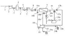
- FIG. 1 is an example of a process flow of a semipermeable membrane water making apparatus (semipermeable membrane separation apparatus) to which the semipermeable membrane blocking performance improving method (step A) of the present invention can be applied.
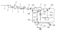
- FIG. 2 is an example of a process flow of a semipermeable membrane water producing apparatus (semipermeable membrane separation apparatus) that can apply the semipermeable membrane blocking performance improving method (step A) according to the present invention to the semipermeable membrane in a reverse flow. is there.
- FIG. 1 is an example of a process flow of a semipermeable membrane water making apparatus (semipermeable membrane separation apparatus) to which the semipermeable membrane blocking performance improving method (step A) of the present invention can be applied.
- FIG. 2 is an example of a process flow of a semipermeable membrane water producing apparatus (semipermeable membrane separation apparatus) that can apply the semipermeable membrane blocking performance improving method (step A) according to the present invention to the semiper
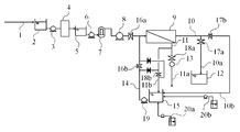
- FIG. 3 shows an example of a process flow of a semipermeable membrane water generator (semipermeable membrane separation device) that can apply the semipermeable membrane blocking performance improving method (step A) according to the present invention to the semipermeable membrane by reverse flow switching. It is.
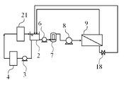
- FIG. 4 is a process flow of the test apparatus used for collecting examples of the semipermeable membrane blocking performance improving method (step A) according to the present invention.
- the operation method of the semipermeable membrane separation device is an operation method of supplying the treated water to the semipermeable membrane unit and obtaining the produced water separated on the permeate side, By pressurizing and supplying a liquid containing a blocking performance improver to the treated water side of the semipermeable membrane unit, the blocking performance improving agent is contacted and adhered to the membrane surface of the semipermeable membrane in the semipermeable membrane unit Step A for improving the blocking performance of the semipermeable membrane, and peeling and removing the blocking performance improving agent attached to the semipermeable membrane with a liquid containing a removing agent, thereby improving the water permeability of the semipermeable membrane.
- Process B to improve The production water is obtained while intermittently carrying out.
- FIG. 1 shows an example of a semipermeable membrane separation apparatus to which the method of improving the performance of blocking a semipermeable membrane of the present invention can be applied as the process A.
- the semipermeable membrane water generator shown in FIG. 1 When the semipermeable membrane water generator shown in FIG. 1 is operated for fresh water, the treated water is temporarily stored in the treated water tank 2 through the treated water line 1, and then supplied with the treated water as necessary. The liquid is sent to the pretreatment unit 4 by the pump 3 and pretreated. The pretreated water passes through the intermediate water tank 5, the pretreated water supply pump 6, and the safety filter 7, and is boosted by the booster pump 8, and is then permeated and concentrated by a semipermeable membrane unit 9 composed of a semipermeable membrane module. To separate.
- the permeated water is stored in the production water tank 12 through the production water line 10a. Concentrated water is discharged out of the system via the concentrated water discharge line 11a after pressure energy is recovered by the energy recovery unit 13 as necessary.
- the supply water valve 16a, the permeated water valve 17a, and the concentrated water valve 18a are opened, and the supplied chemical liquid valve 16b, the permeated chemical liquid valve 17b, and the concentrated chemical liquid valve 18b are closed.
- a chemical circulation line can be used.
- the chemical solution circulation line includes a chemical solution tank 15, a chemical solution supply pump 19, and a chemical solution addition unit 20a.
- the chemical solution is supplied from the chemical solution supply line 14 to the semipermeable membrane unit 9, and the permeated chemical solution (all solutes are blocked depending on the type of the chemical solution). Therefore, in this case, only the solvent) passes through the permeated water line 10 and the permeated chemical liquid line 10b, and the concentrated chemical liquid that has not permeated passes through the concentrated water line 11 and the concentrated chemical liquid line 11b, and passes through the chemical liquid tank 15.
- To reflux is only the solvent
- the supply water valve 16a, the permeate water valve 17a, and the concentrated water valve 18a are closed, and the supply chemical liquid valve 16b, the permeate chemical liquid valve 17b, and the concentrated chemical liquid valve 18b are opened.
- medical solution circulation line can be utilized also when circulatingly washing a semipermeable membrane using an acid, an alkali, a detergent, etc.
- a liquid containing a blocking performance improver is pressurized and supplied to the primary side (treated water side) of the semipermeable membrane in the semipermeable membrane unit, and the blocking performance improver is applied to the membrane surface of the semipermeable membrane.
- the semipermeable membrane is peeled and removed with a liquid containing a removing agent, the step A for improving the blocking performance of the semipermeable membrane by contact adhesion and the blocking performance improver attached to the semipermeable membrane.
- the process A is prescribed to improve the blocking performance of the semipermeable membrane.
- the conditions for prescribing step A are when the quality of the produced water exceeds or exceeds the reference value.
- prescription can also be determined based on the parameter calculated based on the solute permeability coefficient of the semipermeable membrane or the solute permeability coefficient.
- parameters include predicted water quality and standard performance.
- the temperature of water to be treated is given as a condition that greatly affects the permeation performance of the semipermeable membrane. That is, at least one selected from the case where the quality of the produced water obtained exceeds the reference value, the case where the solute permeability coefficient of the semipermeable membrane exceeds the reference value, and the case where the water temperature of the treated water exceeds the reference value In the case of 1, it is preferable to carry out the step A.
- the water temperature of the water to be treated has the greatest influence on the quality of the produced water and is easy to measure. Therefore, it is also preferable to prescribe the step A based on the water temperature.
- process A can be prescribed based on the production water flow rate and operating pressure, or based on the parameters calculated based on the pure water permeability coefficient and the pure water permeability coefficient of the semipermeable membrane. It can also be determined to prescribe step A.
- the parameters include the production water flow rate, the predicted value of the operating pressure, standard performance, and the like. Such control is suitable when wastewater treatment, landscape water, etc., not only the water quality but also the amount of water is important.
- step B when the operating pressure is higher than the reference value, the flow rate of the produced water is lower than the reference value, the pure water permeability coefficient of the semipermeable membrane is lower than the reference value, and the water temperature of the treated water is the reference It is preferable to carry out the step B in at least any one selected from cases where the value is lower than the value.
- the case where the operating pressure exceeds the reference value includes the case where the production water quality falls below the reference value (when it is within the reference value), etc.
- the prescription can be determined based on parameters calculated based on the solute permeability coefficient of the membrane or the solute permeability coefficient of the semipermeable membrane.
- the condition setting method for shifting to the process A or the process B is not particularly limited, but the process A is a process that contributes to the improvement of the production water quality, and the process B contributes to the improvement of the production water volume (or operating pressure).
- prescribe process A when the production water quality exceeds the standard value, and prescribe process B when the production water volume falls below the standard value (or when the operating pressure exceeds the standard value) Is preferred.
- the production water quality is important, even if the production water flow rate is lower than the reference value or the operating pressure is higher than the reference value, a decrease in the production water flow rate is acceptable as long as the production water quality is not lower than the reference value. It is preferable to control so that the process B is not prescribed within the range. If neither the production water quality nor the production water flow rate can meet the standard values, the semipermeable membrane can be washed, but if the water quality does not improve by washing, the semipermeable membrane may be replaced with a new one. Necessary.
- the process A is performed at a time when the water temperature is expected to rise in the future (water temperature rising period between the lowest water temperature period and the highest water temperature period), and the process B is performed. It is convenient and preferable to carry out with the approximate condition setting at the time when the water temperature is expected to drop in the future (water temperature lowering period between the highest water temperature period and the lowest water temperature period).
- the process A is prescribed in the first week of April, and the water temperature from the summer when the water temperature is high
- Step B is performed once when the temperature falls to or below.
- Such a method is a particularly preferable operation method particularly in the case of a small-scale apparatus or when it is not easy to closely collect water quality, temperature, and the like.
- a blocking performance improving method as shown in the background art can be applied. Further, when the inhibition performance improving process is performed, it is possible to select the type of solute and its concentration depending on the type of the inhibition performance improving agent and the state of the semipermeable membrane, as described below.
- the blocking performance improver has a low concentration and the permeation flux is large, and at the outlet, the blocking performance improver has a high concentration and permeation. Since the flux is small, the blocking performance improver that comes into contact is preferable because the balance from the inlet to the outlet is improved. Further, depending on the operating conditions, it is possible to make the effect expression rate at the entrance relatively large or relatively low. Specifically, as in the case A, for example, when the change in the influence of the semipermeable membrane on the semipermeable membrane from the inlet to the outlet is small, such as the temperature of the feed water to be treated, or the semipermeable membrane If there is some change in the effect, the combination of improver H + solute H is suitable.
- the permeation flux in the water is larger and easier to foul in the vicinity of the outlet, and the oxidizing agent is semipermeable membrane.
- the effect of the oxidizing agent is greater near the entrance, and the semipermeable membrane is also relatively deteriorated. Therefore, in such a case, a method in which the vicinity of the inlet is positively treated by a combination of the improver L + solute H is suitable.
- this method is particularly suitable.
- Reverse C and case D that is, improver preferentially improves the vicinity of the outlet at the time of desalination with improver L + solute H, or improve the preferential performance of the vicinity of the inlet at the time of desalination with improver H + solute L Can be made.
- a vinyl polymer or a compound having a polyalkylene glycol chain is typical, and a compound having a polyalkylene glycol chain is preferably contained.
- the vinyl polymer include polyvinyl acetate, polyvinyl alcohol, vinyl acetate-ethylene copolymer, Bolipier alcohol, vinyl acetate-ethylene copolymer, vinyl chloride copolymer, styrene-vinyl acetate copolymer, and N vinyl pyrrolidone.
- -A vinyl acetate copolymer etc. can be illustrated.
- polyalkylene glycol chain examples include a polyethylene glycol chain, a polypropylene glycol chain, a polytrimethylene glycol chain, and a polytetramethylene glycol chain.
- These glycol chains can be formed by, for example, ring-opening polymerization of ethylene oxide, propylene oxide, oxetane, tetrahydrofuran or the like.
- the blocking performance improver applied to the present invention is required to contain other solutes, but the component is not particularly limited, but an oxidizing agent that affects the performance of the semipermeable membrane, It should be noted that turbidity, compounds such as surfactants that adsorb to the membrane and cause performance degradation, and components such as organic solvents and oils are not included. From this viewpoint, it is particularly preferable to apply a compound having a polyalkylene glycol chain to a semipermeable membrane containing polyamide as a main component, since the effect is large.
- the compound having a polyalkylene glycol chain of the present invention a compound in which an ionic group is introduced into the polyalkylene glycol chain can be used.
- the ionic group include a sulfo group, a carboxy group, a phospho group, an amino group, and a quaternary ammonium group.
- a water-soluble polymer compound having anionic or cationic characteristics can be obtained.
- the polyalkylene glycol chain in the present invention is particularly preferably a polyethylene glycol chain. Since the compound having a polyethylene glycol chain is highly water-soluble, it is easy to handle as a blocking rate improver and has a high affinity for the composite membrane surface, so that there is little deterioration in performance over time after treatment.
- the improver L and the solute L those having a blocking performance of a semipermeable membrane to be applied of 50% or less are preferable, and blocking performance of 20% or less is more preferable.
- the improver H or solute H preferably has a semipermeable membrane blocking performance of 70% or more, more preferably 90% or more.
- the polymer to which the present invention is applied can be appropriately selected according to the component whose semipermeable membrane performance or blocking performance is desired to be improved.
- the weight average molecular weight is preferably 6,000 or more and 100,000 or less. More preferably, it is 7,500 to 50,000.
- the weight average molecular weight of the polyalkylene glycol chain is less than 6,000, the blocking rate of the semipermeable membrane is not sufficiently improved, and the fixability after processing may be lowered.
- a blocking performance improver having a weight average molecular weight of 2,000 or less is preferable, and a weight average molecular weight of 2,000 or less It is more effective to contain an alkylene glycol chain.
- the removal rate of 2,000 mg / L sodium chloride is preferably 99.5% or more, particularly preferably when applied to a high removal rate membrane that expresses 99.8% or more. It is.
- the weight average molecular weight of the polyalkylene glycol as a blocking rate improver is 100 or more to 100 000 or less is effective.
- polyvalent glycol having a weight average molecular weight of 20,000 or more is used. This is more preferable because the removal performance of divalent ions can be increased without increasing the ion blocking performance as much as possible.
- the weight average molecular weight can be obtained by analyzing an aqueous solution of a compound having a polyalkylene glycol chain by gel permeation chromatography (GPC) and converting the obtained chromatogram into the molecular weight of a polyethylene oxide standard product.
- GPC gel permeation chromatography
- the blocking performance improver H is used as the blocking performance improver of the present invention because of the high blocking performance of the semipermeable membrane.
- the weight average molecular weight is preferably 2,000 or more and 50,000 or less, and particularly preferably 2,000 or more and 20,000 or less.
- the weight average molecular weight is 6,000 or more and 100,000. The following is preferable.
- the blocking performance improving agent acts even inside the semipermeable membrane if the permeation flux is 0.01 to 2.0 m / day. It is easy to do and preferable. When the permeation flux is 0.01 m / day or less, the treatment effect is low, and when it is 2.0 m / day or more, there is a possibility that the composite semipermeable membrane may be damaged by excessive operating pressure.
- the concentration of the blocking performance improver is not particularly limited, but if the concentration is too high, it may be difficult to obtain a uniform blocking performance improvement over the entire film, and the blocking performance improving agent accumulates locally. Therefore, local water permeability deterioration may occur. On the other hand, if the concentration is too low, the speed of improving the blocking performance is reduced, and the processing time may be increased. Specifically, it is preferably 0.5 ⁇ mol / L or more and 100 ⁇ mol / L or less, and more preferably 1 ⁇ mol / L or more and 50 ⁇ mol / L or less.
- the concentration can be gradually increased and decreased while monitoring the permeation flux during the prevention performance improvement treatment.
- the concentration can be gradually increased and decreased while monitoring the permeation flux during the prevention performance improvement treatment.
- the diffusion / contact speed to the semipermeable membrane can be increased by heating and supplying the liquid containing the blocking performance improver.
- the operating temperature at the time of water generation of the semipermeable membrane and from the meaning of preventing deterioration due to the heat of the semipermeable membrane, it is preferably not less than the maximum temperature at the time of water formation and not more than 60 ° C. The temperature is from 35 ° C to 45 ° C.
- desorb a blocking performance improvement agent from a semipermeable membrane by making high temperature water contact after a blocking performance improvement process.
- a specific method it is possible to raise the ambient temperature, but after the prevention performance improvement treatment, supply water, concentrated water, permeated water, and other water outside the system during fresh water generation operation It can be carried out by passing water through the semipermeable membrane supply side at a temperature equal to or higher than the maximum temperature.
- the specific temperature is preferably 60 ° C. or lower, more preferably 35 ° C. or higher and 45 ° C. or lower from the viewpoint of preventing the semipermeable membrane from deteriorating and higher than the maximum temperature during fresh water generation operation.
- the conditions such as the flow rate and pH at that time are not particularly limited, but it is preferably a mild flow rate and pH that do not adversely affect the semipermeable membrane and the inhibition performance improvement treatment result.
- the pressure at this time is below the operation pressure at the time of fresh water generation.
- the pressure of the liquid to be treated during the treatment that is, the pressure on the primary side.
- count is not limited, It is also preferable to implement intermittently, monitoring an effect.
- a similar effect can be obtained by changing the permeation flow rate.
- it can be achieved even by a primary pressure change, but it can also be achieved by a secondary pressure change.
- it is possible to change the permeation flux by changing the membrane surface osmotic pressure by changing the concentration of the solute shown in the present invention.
- the osmotic pressure can be greatly varied without incurring chemical costs.
- it is effective to change the permeation flux by 0.8 times or less before the change, or 1.2 times or more before the change, but a sudden change places a load on the semipermeable membrane. Therefore, more preferably, it is 0.6 times or more and 0.8 times or less, or 1.2 times or more and 1.5 times or less.
- the time for passing the liquid containing the blocking performance improver can be appropriately determined according to the present invention, but it is preferably 0.5 to 24 hours, and more preferably 1 to 12 hours. As described above, if the processing time is too short, uniform processing may be difficult, and if it is too long, the operating time of the equipment may be lost.
- step A When performing the inhibition performance improvement process (step A), a more sustainable recovery effect can be obtained by removing the membrane contaminants on the semipermeable membrane surface in advance before the contact treatment. That is, it is preferable to clean the semipermeable membrane before performing the step A.
- chemicals generally used as cleaning chemicals for these films can be used.
- Metals such as iron and manganese adhering to the film surface are preferable because they are more effective in washing with acidic solutions such as citric acid, oxalic acid, hydrochloric acid, sulfuric acid, etc. Can be further enhanced.
- cleaning with an alkaline solution such as caustic soda or ethylenediaminetetraacetic acid tetrasodium is effective, and the cleaning effect can be enhanced by using a pH of 10 or more.
- the cleaning with these cleaning chemicals may be a method of cleaning using each chemical alone or a method of cleaning using a plurality of chemicals alternately. It is also possible to mix cleaning chemicals with a blocking performance improver and perform cleaning and step A simultaneously.
- a liquid in which a blocking performance improving agent and a solute are added in advance to the chemical tank 15 can be prepared, for example, as shown in FIG.
- a blocking performance improver can be added by the addition unit 20a, and a solute can be added by the chemical solution addition unit 20b.
- any of the semipermeable membrane supply water, the semipermeable membrane concentrated water, and the semipermeable membrane permeated water is supplied to the chemical tank 15 and supplied and stored before or after the water production operation.
- the blocking performance improver is added from the chemical solution addition unit 20a to a predetermined concentration. Accordingly, it is not necessary to procure the solute / solvent for the liquid of the present invention from outside the system, and it becomes possible to prepare a liquid having an osmotic pressure according to the purpose.
- semipermeable membrane permeated water may be used as a solvent, and the solute may be supplied from outside the system, that is, by the chemical solution addition unit 20b.
- the liquid containing the blocking performance improver performs the process A while obtaining the production water using the liquid obtained by adding the blocking performance improver to the treated water, that is, blocking the treated water. It is particularly efficient to carry out fresh water generation and inhibition performance improvement process (step A) while adding a performance improver. That is, it is possible to perform the treatment and the water preparation at the same time by pretreating the raw water to be treated and adding a blocking performance improver to the pretreatment water.
- the fresh water operation pressure, the fresh water generation amount and the permeated water quality can be monitored in real time, which is very preferable from the viewpoint of control. That is, for example, when the permeated water quality, rejection rate, and / or solute permeation coefficient is worse than the set concentration, a blocking performance improver is added, and when the blocking performance falls within an allowable value, the addition is stopped. This is very preferable. However, in this case, in the unlikely event, there is a risk that the blocking performance improver is mixed into the produced water.
- a process to further treat the permeated water is provided so that the blocking performance improver is not mixed into the production water, a blocking performance improving agent whose safety has been confirmed for the application is used, or the blocking performance in the permeated water is improved. It is necessary to take measures such as strictly monitoring the concentration of the agent and immediately stopping fresh water.
- step B the semipermeable membrane may or may not be cleaned before step B.
- step B can be more effectively performed.
- the blocking performance improver adhered to the membrane surface of the semipermeable membrane in Step B is removed and at the same time the membrane contaminants are removed. That is, it is more preferable that the semipermeable membrane is cleaned simultaneously with the step B.
- step B when the inhibitory performance improver used in step A contains a compound having a polyalkylene glycol chain, as a remover in step B, (i) a surfactant or (Ii) It is preferable to use a remover containing a compound having at least any one selected from a pyridine ring, an alkylamine chain and a piperidine ring. Furthermore, (iii) It is preferable that the liquid containing the removal agent is alkaline, since the removal effect is high. That is, it is preferable to satisfy at least one of the above (i) to (iii). Above all, in the case of (iii) above, if the removing agent is a highly alkaline liquid, the alkali cleaning of the semipermeable membrane and the step B can be performed at the same time, which is a very preferable embodiment.
- the process B is performed from the permeated water side of the semipermeable membrane unit during the process B. It is effective to allow water or a solution to permeate the water side.
- this method in addition to a method of applying pressure from the permeate side to the treated water side, a method in which water having a lower osmotic pressure than the removing agent-containing liquid on the treated water side is contacted and water is permeated through normal osmosis. It can also be preferred.
- the membrane structure also has a dense layer on at least one side of the membrane, and an asymmetric membrane having fine pores with gradually increasing pore diameters from the dense layer to the inside of the membrane or the other side, or another material on the support membrane It is possible to use a composite semipermeable membrane having a very thin separation functional layer formed in (1).
- the semipermeable membrane suitable for the present invention is a composite reverse osmosis membrane having a high pressure resistance, high water permeability, and high solute removal performance and having excellent performance, and a polyamide separation function layer, or a nanofiltration membrane. preferable.
- the polyamide semipermeable membrane As the polyamide semipermeable membrane, a composite semipermeable membrane having a separation functional layer of a crosslinked polyamide obtained by a polycondensation reaction between a polyfunctional amine and a polyfunctional acid halide is preferable. Furthermore, the composite semipermeable membrane is preferable in that the amount of the separation functional layer is small, and therefore the blocking performance improver effectively acts on the functional layer portion that exhibits blocking performance.
- the pH of general raw water to be treated is in a neutral region, and the membrane surface is negatively charged in this region in order to prevent adsorption of natural organic substances. That is, since the membrane surface potential is negative, the isoelectric point, that is, the surface potential of the membrane is generally 0 in the weakly acidic region.
- the sustainability of the processing effect can be enhanced by neutralizing the surface potential of the semipermeable membrane. Therefore, the treatment is preferably carried out in a weakly acidic region, specifically pH 4 or more and pH 7 or less, more preferably pH 5.5 or more and pH 6.8 or less.
- the semipermeable membrane can be used as a semipermeable membrane element shaped for practical use.
- the semipermeable membrane is a flat membrane, it can be used by being incorporated into a spiral, tubular, or plate-and-frame module.
- the spiral shape due to its structure, the blocking performance improver becomes a one-way flow from one end surface to the opposite end surface, and members such as a feed water side channel material and a permeate side channel material are incorporated. Therefore, the blocking performance improver tends to act uniformly on the membrane surface and is particularly preferably used as a semipermeable membrane element to which the present invention is applied.
- the feed water side channel material through which the liquid containing the blocking performance improver is passed preferably has a thickness of 0.6 mm or more and 1.0 mm or less, particularly preferably 0.7 m or more and 0.9 mm or less. . Further, it is preferable to apply to a spiral element having a porosity of 0.8 or more because the treatment liquid can be easily contacted evenly.
- the blocking performance improving method (step A) of the present invention improves the blocking rate of the semipermeable membrane by bringing the liquid containing the blocking performance improving agent into contact with the semipermeable membrane, but the permeation flux decreases accordingly. . Therefore, it is very important to monitor and manage the water permeation performance before and after the prevention performance treatment and the prevention performance in order to prevent the excessive increase of the operating pressure due to the deterioration of the water permeability performance while fully utilizing the effect of improving the prevention performance. It is.
- components other than containing the blocking performance improving treatment agent are passed through the reverse osmosis membrane using the same liquid, and the supply water, permeated water and concentrated water at that time are passed. among them, at least two flow rate and concentration, the water temperature was measured, pure water permeability therefrom as an initial water permeability coefficients a 0, and calculates the solute permeability coefficient B 0 as rejection performance.
- the solute permeability coefficient B 0 is calculated as rejection performance.
- the R A1 is 0.9 or less, and, together with R A2 is so is 0.7 or more, rejection performance as R B is 0.3 to 0.7 More preferably, an improvement treatment is performed.
- the pure water permeability coefficient A and the solute permeability coefficient B in the present invention can be determined by the following method.
- Jv A ( ⁇ P ⁇ (Cm)) (1)
- Cp Js / Jv (4)
- A ⁇ ⁇ A25 ⁇ ⁇ 25 / ⁇ (5)
- B ⁇ ⁇ B25 ⁇ ⁇ 25 / ⁇ ⁇ (273.15 + T) / (298.15)
- Cf Supply water concentration [mg / l]
- Cm film surface concentration [mg / l]
- Cp Permeated water concentration [mg / l]
- Js Solute permeation flux [kg / m 2 / s]
- Jv pure water permeation flux [m 3 / m 2 / s]
- k Mass transfer coefficient [m / s
- the pure water permeability coefficient A and the solute permeability coefficient B under the measured conditions. can be requested. Furthermore, based on the values of the coefficients ⁇ and ⁇ obtained in advance, the pure water permeability coefficient A25 and the solute permeability coefficient B25 at 25 ° C. can be obtained from the equations (5) and (6), respectively. Using the equations (5) and (6), the pure water permeability coefficient and solute permeability coefficient at an arbitrary temperature T can also be obtained. Moreover, when calculating the performance of a semipermeable membrane element, it can obtain
- the pure water permeability coefficient A and the solute permeability coefficient B are values corrected to the same temperature, but the most severe for water permeability, that is, the pure water permeability coefficient A is the lowest. the most stringent for the lowest operating temperature T L, and rejection performance of the semipermeable membrane, i.e. the solute permeability coefficient B is corrected to a value at the maximum operating temperature T H of the largest becomes a semi-permeable membrane, or the performance of each is within the allowable range It is very preferable because it is easy to understand.
- step A in order to perform the step A, for example, there is a method in which a liquid containing a blocking performance improver is passed through the pressure vessel in a state where the semipermeable membrane is loaded in the pressure vessel, and is processed by contacting with the semipermeable membrane. It is done. If there is equipment for chemical cleaning with the semipermeable membrane loaded in the pressure vessel, use the washing equipment to pass the liquid containing the blocking performance improver through the pressure vessel and contact the semipermeable membrane. can do.
- the pressure when the aqueous solution containing the blocking performance improver is contacted with the composite semipermeable membrane is not particularly limited, and should be appropriately determined in view of the pressure resistance of the semipermeable membrane, the blocking performance improving effect and the influence on water permeability. Can do. Among them, it is preferable that the water to be treated is passed through the semipermeable membrane and the pressure is equal to or lower than the pressure at the time of fresh water generation operation. Then, since the prevention performance improvement process can be performed without providing dedicated equipment, it is more preferable.
- the blocking performance improving agent can reach the inside of the semipermeable membrane if the permeation flux is 0.01 to 2.0 m / day. It is easy to act and preferable. When the permeation flux is 0.01 m / day or less, the treatment effect is low, and when it is 2.0 m / day or more, the composite semipermeable membrane may be damaged by excessive operating pressure.
- the method for improving the blocking performance of the present invention can improve the blocking rate with repeated effects on the same semipermeable membrane in the same water treatment equipment, so the processing method of the present invention is periodically performed.
- the effect of improving the removal rate of uncharged substances is greater than that of inorganic electrolytes that have an effect of eliminating membrane charges.
- the non-charged substance include non-electrolyte organic substances and substances that are not separated in the neutral region (for example, boron and silica). Since these are contained in a large amount in seawater and groundwater, it is possible to continue more stable operation by applying the method of the present invention to a desalination plant for treating these raw waters.
- FIG. 4 shows the flow.
- the apparatus shown in FIG. 4 is a treated water tank 2, treated water supply pump 3, and pretreatment unit 4, a UF filtration module filled with activated carbon, a pretreated water supply pump 6, a safety filter 7, a booster pump 8, a semi-permeable
- the membrane unit 9, the concentrated water valve 18, and the temperature adjustment unit 21, and the water to be treated are maintained as clear water to be treated by circulating through the pretreatment unit 4 and the temperature regulation unit 21.
- ⁇ Degraded film performance> By immersing the same membrane as the membrane used in ⁇ New membrane performance> above in a 100 mg / L aqueous solution of hypochlorous acid for 2 hours for chemical deterioration, and then supplying evaluation feed water to the membrane at 45 ° C. and 7 MPa. A deteriorated film having been physically deteriorated was prepared.
- the operating pressure was 5.16 MPa, and the permeated water NaCl concentration at that time was 150 mg / L, which was 100 mg / L. Exceeded.
- the water temperature was lowered to 10 ° C.
- the operating pressure was 6.23 MPa
- the permeated water quality was 70 mg / L.
- ⁇ Improved membrane performance> For the deteriorated film used in the above ⁇ deteriorated film performance>, a liquid obtained by adding 2 ⁇ mol / L of polyethylene glycol having a weight average molecular weight of 8,000 as a blocking performance improver to pure water using the same flat film evaluation apparatus, Circulation was performed at a pressure of 3.5 L, 25 ° C., and 0.45 MPa. At this time, the permeated water and the concentrated water were all recycled. The average permeation flux during the treatment was 0.16 m / day.
- the operating pressure was 6.4 MPa
- the permeated water quality was 70 mg / L
- the operating pressure was 7 MPa or less
- the permeated water quality was 100 mg / L or less.
- the permeated water quality was 98 mg / L
- the water quality was improved to 100 mg / L or less by the inhibition performance improving treatment.
- the permeated water quality was sufficiently good at 45 mg / L, but the operating pressure rose to 7.5 MPa and exceeded 7 MPa.
- the operating pressure was 5.7 MPa
- the permeated water quality was 94 mg / L
- the operating pressure was 7 MPa or less
- the permeated water quality was 100 mg / L or less.
- the permeated water quality was 140 mg / L
- the water quality deteriorated by exceeding 100 mg / L by the removal treatment.
- the permeated water quality was sufficiently good at 63 mg / L
- the operating pressure was 6.3 MPa, which was much lower than 7 MPa.
- Example 1 From the above performance evaluation results, when the water temperature fluctuation in one year is assumed to be 10 ° C to 40 ° C in the situation where the membrane has deteriorated, it is prevented from 25 ° C to over 25 ° C, that is, winter ⁇ spring ⁇ summer If the performance-enhancing treatment is performed, and the anti-blocking performance-improving agent is removed from 25 ° C to below 25 ° C, that is, summer ⁇ autumn ⁇ winter, the maximum pressure in winter (10 ° C) is 6.3 MPa, summer It was suggested that the maximum permeated water quality (40 ° C.) was 95 mg / L, and that 100 mg / L could always be maintained with the equipment capacity of the operating pressure of 7 MPa or less.
- Table 1 shows a summary of the examples and comparative examples.
- the present invention relates to a semipermeable membrane separation apparatus using a semipermeable membrane such as a nanofiltration membrane or a reverse osmosis membrane, and is capable of improving the semipermeable membrane blocking performance, particularly the blocking performance of nonionic substances. It is a semipermeable membrane separator operation method that efficiently combines an improvement process and a cleaning process that recovers performance degradation due to fouling, and this makes it possible to produce fresh water while stably achieving both energy saving and production water quality. It becomes possible.
Landscapes
- Chemical & Material Sciences (AREA)
- Chemical Kinetics & Catalysis (AREA)
- Life Sciences & Earth Sciences (AREA)
- Hydrology & Water Resources (AREA)
- Engineering & Computer Science (AREA)
- Environmental & Geological Engineering (AREA)
- Water Supply & Treatment (AREA)
- Organic Chemistry (AREA)
- Separation Using Semi-Permeable Membranes (AREA)
Abstract
本発明は、阻止性能向上工程と性能低下を回復させる洗浄工程を効率的に併用することによって省エネと生産水質を安定的に両立させる淡水製造方法を提供することを目的とする。本発明は半透膜の膜面に阻止性能向上剤を接触付着させることによって前記半透膜の阻止性能を向上させる工程A、及び、前記半透膜に付着した前記阻止性能向上剤を、除去剤を含有する液体で剥離除去することによって前記半透膜の透水性能を向上させる工程Bを断続的に実施しながら、生産水を得る半透膜分離装置の運転方法に関する。
Description
本発明は、海水や、塩分を含む河川水、地下水、湖水、廃水処理水などの原水を用いて、低濃度の透過水を生産水として得るための半透膜分離装置の運転方法に関するものであり、さらに詳しくは、半透膜の透水性能と阻止性能とを適切に維持し、省エネと生産水質を両立させることができる半透膜分離装置の運転方法に関するものである。
近年、水資源の枯渇が深刻になりつつあり、これまで利用されてこなかった水資源の活用が検討されている。特に、もっとも身近でそのままでは利用できなかった海水から飲料水を製造する技術、いわゆる“海水淡水化”や、さらには、下廃水を浄化し、処理水を淡水化する再利用技術が注目されてきている。
海水淡水化は、従来、水資源が極端に少なく、かつ、石油による熱資源が非常に豊富である中東地域で蒸発法を中心に実用化されてきている。一方、熱源が豊富でない中東以外の地域ではエネルギー効率の高い逆浸透法が採用されており、最近では、逆浸透法の技術進歩による信頼性の向上やコストダウンが進み、中東を含む多くの地域において、逆浸透法海水淡水化プラントが建設され、世界的な展開を見せつつある。
下廃水再利用は、内陸や海岸沿いの都市部や工業地域で、淡水源がないようなところや排水規制のために放流量が制約されているようなところに適用され始めている。特に、水源が乏しい島国のシンガポールでは、国内で発生する下水を処理後、海に放流せずに貯留し、逆浸透膜で飲料できるレベルの水にまで再生し、水不足に対応している。
このような海水淡水化や下廃水再利用に適用される逆浸透法は、塩分などの溶質を含んだ水を浸透圧以上の圧力をもって半透膜を透過させることで、脱塩された水を製造するものである。この技術は例えば海水、かん水、有害物を含んだ水から飲料水を得ることも可能であるし、また、工業用超純水の製造、排水処理、有価物の回収などにも用いられてきた。
逆浸透膜による淡水化装置を安定運転させるためには、取水する原水水質に応じた前処理が必要である。前処理が不十分だと、逆浸透膜を劣化させたりファウリング(膜面汚れ)させることがあり、安定運転が困難になりやすい。特に、逆浸透膜を劣化させる化学物質が逆浸透膜に侵入した場合、洗浄によっても回復不能な致命的な状況に陥る可能性がある。すなわち、逆浸透膜の機能層(逆浸透機能を発現する部分)が分解し、水と溶質の分離性能、言い換えると、溶質の阻止性能が低下する。
海水淡水化や下廃水再利用などの用途に逆浸透膜を用いる場合、このような逆浸透膜の機能層の分解を100%生じないようにすることは非常に難しく、特に、逆浸透膜の主流であるポリアミドは、酸化劣化を生じやすい(非特許文献1)。また、ある程度の耐久性は有するものの強い酸やアルカリにさらされた場合も、機能層の分解が起こりやすい。
このような分解が起こった場合、水処理用逆浸透膜として一般的なアニオン荷電を有する半透膜の場合には、アニオン荷電による荷電排除効果によって阻止可能な無機電解質の分離除去よりも、中性分子の除去への悪影響が大きく、特に中性分子の阻止率が悪くなる。具体的には、中性領域で解離していないシリカやホウ素、糖類などの水質悪化が著しくなる。
必要な阻止性能を失った逆浸透膜は、通常、新品と交換しなければならなくなるため、当然処理コストの増加につながる。
必要な阻止性能を失った逆浸透膜は、通常、新品と交換しなければならなくなるため、当然処理コストの増加につながる。
このため、長年にわたって、逆浸透膜の阻止性能を回復させる技術の開発が進められており、ビニル系ポリマーを接触、反応させる方法(特許文献1、2)、ポリエチレングリコールを逆浸透膜に接触させて阻止率、特に非イオン性溶質に対する阻止率を向上させる方法(特許文献3、4)、透過流束が増加したアニオン荷電を有する逆浸透膜に対し、ノニオン系界面活性剤を膜面に接触させる方法(特許文献5)、酸化還元電位が300mV以上であるヨウ素及び/またはヨウ素化合物を接触させる方法(特許文献6)、燐酸、亜燐酸、硫酸等の強鉱酸水溶液と接触させて昇温した後、加水分解性タンニン酸などの阻止性能向上剤に接触させる方法(特許文献6)など、数々の逆浸透膜の阻止性能回復方法やそのための回復剤が提案されている。
しかしながら、これらの阻止性能回復処理は、様々な技術課題を抱えている。
しかしながら、これらの阻止性能回復処理は、様々な技術課題を抱えている。
すなわち、逆浸透膜の種類や状態(汚れ、劣化)、水温などの処理環境、処理を実施するときの条件(処理液の温度、濃度、処理時間など)によって阻止性能向上処理効果が変わったり、阻止性能向上処理の副作用とも言える透水性能低下も変化する。また、阻止率向上後の長期性能持続効果などもまちまちであり、阻止性能向上処理後の造水運転において水質が不十分であったり、運転圧力が不足したり、困難を伴う場合が少なくない。
2000年代になってから急速に建設され稼働開始している大型の海水淡水化や下水再利用プラントでは、逆浸透膜を多数使用していることや海水など自然環境中の原水を処理するため、たとえ前処理をしても、季節、潮の満ち引き、赤潮その他、天候や自然環境の影響を受けながら逆浸透膜の運転がなされることとなる。すなわち、逆浸透膜の状態も同じプラントの中でも様々であり、技術課題も様々である。
また、阻止性能向上処理のためには、一旦通常の造水処理を停止した後、薬液洗浄ラインを通して、運転時の被処理原水に変えて阻止性能向上剤に置き換える。そのため、稼働率が低下する、手間が煩雑である、また、処理終了後に、再度、被処理原水を通水して通常運転条件で阻止性能や透水性能も測定しなければ最終的な効果が判らないなど、多くの問題を抱えている。
これらの問題に対し、逆浸透膜の状態の違いによる処理効果への影響を解決するためには、例えば、特許文献8に例示されるように、逆浸透膜を薬液洗浄した後に阻止性能向上処理を施す技術が一般的に適用されている。また、特許文献9に示すように高温水で洗浄してから阻止性能向上剤に接触させるといった前処理も提案されている。
阻止性能向上処理の効果を判断する方法としては、阻止性能向上剤に標識となる物質を添加し、透過水中の標識物質の濃度を検出することによって処理効果を確認する方法(特許文献10)が提案されている。
阻止率向上処理が飽和に達し、それ以上無駄な回復処理時間を要することがないように、阻止性能向上剤の供給濃度と排出濃度を監視して、処理の終了を判定する方法も提案されている(特許文献11)。
阻止率向上処理が飽和に達し、それ以上無駄な回復処理時間を要することがないように、阻止性能向上剤の供給濃度と排出濃度を監視して、処理の終了を判定する方法も提案されている(特許文献11)。
植村忠廣ら、複合逆浸透膜の退園組成と塩素劣化による膜構造、膜分離特性の変化、日本海水学会誌、第57巻、第3号(2003)
M.Taniguchiら、Boron Reduction performance of reverse osmosis seawater desalination process、ジャーナル・オブ・メンブレン・サイエンス、183、259-267(2000)
しかし、上記の方法はいずれも、阻止性能向上の代償として、透水性能が低下し、運転圧力が増大することが避けられなかった。
そこで本発明は、ナノろ過膜や逆浸透膜などの半透膜を用いた半透膜分離装置に対し、半透膜の阻止性能、特に非イオン性物質の阻止性能を向上させることができる阻止性能向上工程とファウリングによる性能低下を回復させる洗浄工程を効率的に併用することで、省エネと生産水質を安定的に両立させる半透膜分離装置の運転方法を提供することを目的とする。
そこで本発明は、ナノろ過膜や逆浸透膜などの半透膜を用いた半透膜分離装置に対し、半透膜の阻止性能、特に非イオン性物質の阻止性能を向上させることができる阻止性能向上工程とファウリングによる性能低下を回復させる洗浄工程を効率的に併用することで、省エネと生産水質を安定的に両立させる半透膜分離装置の運転方法を提供することを目的とする。
前記課題を解決するために、本発明は次の構成をとる。
(1) 被処理水を半透膜ユニットに供給して、透過水側に分離処理された生産水を得る半透膜分離装置の運転方法であって、
前記半透膜ユニットの前記被処理水側に阻止性能向上剤を含有する液体を加圧供給し、前記半透膜ユニットにおける半透膜の膜面に前記阻止性能向上剤を接触付着させることによって、前記半透膜の阻止性能を向上させる工程A、及び
前記半透膜に付着した前記阻止性能向上剤を、除去剤を含有する液体で剥離除去することによって、前記半透膜の透水性能を向上させる工程B
を断続的に実施しながら生産水を得る、半透膜分離装置の運転方法。
(2) 得られる生産水の水質が基準値を上回る場合、前記半透膜の溶質透過係数が基準値を上回る場合、及び、前記被処理水の水温が基準値を上回る場合から選ばれる少なくともいずれか1の場合に前記工程Aを実施し、
運転圧力が基準値を上回る場合、得られる生産水の流量が基準値を下回る場合、前記半透膜の純水透過係数が基準値を下回る場合、及び、前記被処理水の水温が基準値を下回る場合から選ばれる少なくともいずれか1の場合に前記工程Bを実施する、前記(1)に記載の半透膜分離装置の運転方法。
(3) 前記工程A及び前記工程Bの少なくともいずれか一方を実施する前に、前記半透膜の洗浄を実施する、前記(1)または(2)に記載の半透膜分離装置の運転方法。
(4) 前記工程A及び前記工程Bの少なくともいずれか一方の実施と同時に、前記半透膜の洗浄を実施する、前記(1)または(2)に記載の半透膜分離装置の運転方法。
(5) 前記工程Bの実施と同時に、前記半透膜の洗浄を実施する、前記(4)に記載の半透膜分離装置の運転方法。
(6) 前記工程Aを前記被処理水の水温が最低水温期から最高水温期の間である水温上昇期に行うとともに、前記工程Bを前記被処理水の水温が前記最高水温期から前記最低水温期の間である水温低下期に行う、前記(1)~(5)のいずれか1に記載の半透膜分離装置の運転方法。
(7) 前記工程Aにおける前記阻止性能向上剤を含有する液体として、前記被処理水に前記阻止性能向上剤を添加した液体を用い、生産水を得ながら前記工程Aを行う、前記(1)~(6)のいずれか1に記載の半透膜分離装置の運転方法。
(8) 前記工程Aにおける前記阻止性能向上剤がポリアルキレングリコール鎖を有する化合物を含有し、かつ、前記工程Bにおいて、(i)前記除去剤が界面活性剤である、(ii)前記除去剤がピリジン環、アルキルアミン鎖及びピペリジン環から選ばれる少なくともいずれか1を有する化合物を含む、及び(iii)前記除去剤を含有する液体がアルカリ性を示す、からなる群より選ばれる少なくとも1を満たす、前記(1)~(7)のいずれか1に記載の半透膜分離装置の運転方法。
(9) 前記工程Bの実施中に、前記半透膜ユニットの前記透過水側から前記被処理水側に水を透過させる、前記(1)~(8)のいずれか1に記載の半透膜分離装置の運転方法。
(10) 前記透過水側から前記被処理水側への水の透過が正浸透によるものである、前記(9)に記載の半透膜分離装置の運転方法。
(1) 被処理水を半透膜ユニットに供給して、透過水側に分離処理された生産水を得る半透膜分離装置の運転方法であって、
前記半透膜ユニットの前記被処理水側に阻止性能向上剤を含有する液体を加圧供給し、前記半透膜ユニットにおける半透膜の膜面に前記阻止性能向上剤を接触付着させることによって、前記半透膜の阻止性能を向上させる工程A、及び
前記半透膜に付着した前記阻止性能向上剤を、除去剤を含有する液体で剥離除去することによって、前記半透膜の透水性能を向上させる工程B
を断続的に実施しながら生産水を得る、半透膜分離装置の運転方法。
(2) 得られる生産水の水質が基準値を上回る場合、前記半透膜の溶質透過係数が基準値を上回る場合、及び、前記被処理水の水温が基準値を上回る場合から選ばれる少なくともいずれか1の場合に前記工程Aを実施し、
運転圧力が基準値を上回る場合、得られる生産水の流量が基準値を下回る場合、前記半透膜の純水透過係数が基準値を下回る場合、及び、前記被処理水の水温が基準値を下回る場合から選ばれる少なくともいずれか1の場合に前記工程Bを実施する、前記(1)に記載の半透膜分離装置の運転方法。
(3) 前記工程A及び前記工程Bの少なくともいずれか一方を実施する前に、前記半透膜の洗浄を実施する、前記(1)または(2)に記載の半透膜分離装置の運転方法。
(4) 前記工程A及び前記工程Bの少なくともいずれか一方の実施と同時に、前記半透膜の洗浄を実施する、前記(1)または(2)に記載の半透膜分離装置の運転方法。
(5) 前記工程Bの実施と同時に、前記半透膜の洗浄を実施する、前記(4)に記載の半透膜分離装置の運転方法。
(6) 前記工程Aを前記被処理水の水温が最低水温期から最高水温期の間である水温上昇期に行うとともに、前記工程Bを前記被処理水の水温が前記最高水温期から前記最低水温期の間である水温低下期に行う、前記(1)~(5)のいずれか1に記載の半透膜分離装置の運転方法。
(7) 前記工程Aにおける前記阻止性能向上剤を含有する液体として、前記被処理水に前記阻止性能向上剤を添加した液体を用い、生産水を得ながら前記工程Aを行う、前記(1)~(6)のいずれか1に記載の半透膜分離装置の運転方法。
(8) 前記工程Aにおける前記阻止性能向上剤がポリアルキレングリコール鎖を有する化合物を含有し、かつ、前記工程Bにおいて、(i)前記除去剤が界面活性剤である、(ii)前記除去剤がピリジン環、アルキルアミン鎖及びピペリジン環から選ばれる少なくともいずれか1を有する化合物を含む、及び(iii)前記除去剤を含有する液体がアルカリ性を示す、からなる群より選ばれる少なくとも1を満たす、前記(1)~(7)のいずれか1に記載の半透膜分離装置の運転方法。
(9) 前記工程Bの実施中に、前記半透膜ユニットの前記透過水側から前記被処理水側に水を透過させる、前記(1)~(8)のいずれか1に記載の半透膜分離装置の運転方法。
(10) 前記透過水側から前記被処理水側への水の透過が正浸透によるものである、前記(9)に記載の半透膜分離装置の運転方法。
本発明の半透膜分離装置の運転方法によれば、ナノろ過膜や逆浸透膜などの半透膜を用いた半透膜分離装置に対し、半透膜の阻止性能、特に非イオン性物質の阻止性能を向上させることができる阻止性能向上工程とファウリングによる性能低下を回復させる洗浄工程を効率的に併用し、省エネと生産水質を安定的に両立させながら淡水を製造することが可能となる。
以下、本発明の好ましい実施の形態を、図面を用いて説明する。ただし、本発明の範囲がこれらに限られるものではない。
本発明に係る半透膜分離装置の運転方法は、被処理水を半透膜ユニットに供給して、透過水側に分離処理された生産水を得る運転方法であって、
前記半透膜ユニットの前記被処理水側に阻止性能向上剤を含有する液体を加圧供給し、前記半透膜ユニットにおける半透膜の膜面に前記阻止性能向上剤を接触付着させることによって、前記半透膜の阻止性能を向上させる工程A、及び
前記半透膜に付着した前記阻止性能向上剤を、除去剤を含有する液体で剥離除去することによって、前記半透膜の透水性能を向上させる工程B
を断続的に実施しながら生産水を得ることを特徴とする。
本発明に係る半透膜分離装置の運転方法は、被処理水を半透膜ユニットに供給して、透過水側に分離処理された生産水を得る運転方法であって、
前記半透膜ユニットの前記被処理水側に阻止性能向上剤を含有する液体を加圧供給し、前記半透膜ユニットにおける半透膜の膜面に前記阻止性能向上剤を接触付着させることによって、前記半透膜の阻止性能を向上させる工程A、及び
前記半透膜に付着した前記阻止性能向上剤を、除去剤を含有する液体で剥離除去することによって、前記半透膜の透水性能を向上させる工程B
を断続的に実施しながら生産水を得ることを特徴とする。
工程Aとして、本発明の半透膜の阻止性能向上方法を適用可能な半透膜分離装置の一例を図1に示す。
図1に示す半透膜造水装置を造水運転する場合、被処理水ライン1を通って被処理水が、被処理水槽2に一旦貯留された後、必要に応じて、被処理水供給ポンプ3で前処理ユニット4に送液され、前処理される。
前処理水は、中間水槽5、前処理水供給ポンプ6、保安フィルター7を経て、昇圧ポンプ8で昇圧された後、半透膜モジュールから構成される半透膜ユニット9で透過水と濃縮水に分離する。
透過水は、生産水ライン10aを経て生産水タンク12に貯留される。濃縮水は、必要に応じてエネルギー回収ユニット13で圧力エネルギーを回収した後、濃縮水排出ライン11aを経由して系外へ放流される。
造水運転中は、供給水バルブ16a、透過水バルブ17a、濃縮水バルブ18aは開かれ、供給薬液バルブ16b、透過薬液バルブ17b、濃縮薬液バルブ18bは閉じられている。
図1に示す半透膜造水装置を造水運転する場合、被処理水ライン1を通って被処理水が、被処理水槽2に一旦貯留された後、必要に応じて、被処理水供給ポンプ3で前処理ユニット4に送液され、前処理される。
前処理水は、中間水槽5、前処理水供給ポンプ6、保安フィルター7を経て、昇圧ポンプ8で昇圧された後、半透膜モジュールから構成される半透膜ユニット9で透過水と濃縮水に分離する。
透過水は、生産水ライン10aを経て生産水タンク12に貯留される。濃縮水は、必要に応じてエネルギー回収ユニット13で圧力エネルギーを回収した後、濃縮水排出ライン11aを経由して系外へ放流される。
造水運転中は、供給水バルブ16a、透過水バルブ17a、濃縮水バルブ18aは開かれ、供給薬液バルブ16b、透過薬液バルブ17b、濃縮薬液バルブ18bは閉じられている。
本発明における阻止性能向上処理(工程A)および、除去剤を用いて阻止性能向上剤を半透膜から剥離除去する処理(工程B)を適用する際には、薬液循環ラインを用いることが出来る。
薬液循環ラインは、薬液槽15、薬液供給ポンプ19、薬液添加ユニット20aからなり、薬液供給ライン14から半透膜ユニット9に供給され、透過した薬液(薬液の種類によっては溶質が全て阻止されるので、その場合は溶媒のみ)が、透過水ライン10、透過薬液ライン10bを経由して、また、透過しなかった濃縮薬液は、濃縮水ライン11、濃縮薬液ライン11bを通って、薬液槽15に還流する。
薬液循環ラインは、薬液槽15、薬液供給ポンプ19、薬液添加ユニット20aからなり、薬液供給ライン14から半透膜ユニット9に供給され、透過した薬液(薬液の種類によっては溶質が全て阻止されるので、その場合は溶媒のみ)が、透過水ライン10、透過薬液ライン10bを経由して、また、透過しなかった濃縮薬液は、濃縮水ライン11、濃縮薬液ライン11bを通って、薬液槽15に還流する。
半透膜の阻止性能向上処理中は、供給水バルブ16a、透過水バルブ17a、濃縮水バルブ18aは閉じられ、供給薬液バルブ16b、透過薬液バルブ17b、濃縮薬液バルブ18bは開かれている。
なお、この薬液循環ラインは、酸、アルカリ、洗剤などを用いて半透膜を循環洗浄する場合にも利用することができる。
なお、この薬液循環ラインは、酸、アルカリ、洗剤などを用いて半透膜を循環洗浄する場合にも利用することができる。
本発明においては、半透膜ユニットにおける半透膜の一次側(被処理水側)に阻止性能向上剤を含有する液体を加圧供給し、半透膜の膜面に前記阻止性能向上剤を接触付着させることによって、前記半透膜の阻止性能を向上させる工程Aと、半透膜に付着した前記阻止性能向上剤を、除去剤を含有する液体で剥離除去することによって、前記半透膜の透水性能を向上させる工程Bを断続的に実施しながら、生産水を得ることによって、生産水に要求される水質(生産水質)を満足させながら、半透膜の透水性能低下を最小限に抑えることが可能になる。
具体的には、得られる生産水質が要求水質(水質基準値)を上回るような状況では、工程Aを処方し、半透膜の阻止性能を改善させる。工程Aを処方する条件としては、生産水質が基準値を上回った場合、もしくは、上回ることが想定される場合である。
また、半透膜の溶質透過係数もしくは、溶質透過係数をもとに算出したパラメータをもとに処方を決定することも出来る。パラメータとしては、生産水質の予測値、標準性能などが挙げられる。
さらには、半透膜の透過性能を大きく左右する条件として、被処理水の水温が挙げられる。
すなわち、得られる生産水の水質が基準値を上回る場合、前記半透膜の溶質透過係数が基準値を上回る場合、及び、前記被処理水の水温が基準値を上回る場合から選ばれる少なくともいずれか1の場合に前記工程Aを実施することが好ましい。
さらには、半透膜の透過性能を大きく左右する条件として、被処理水の水温が挙げられる。
すなわち、得られる生産水の水質が基準値を上回る場合、前記半透膜の溶質透過係数が基準値を上回る場合、及び、前記被処理水の水温が基準値を上回る場合から選ばれる少なくともいずれか1の場合に前記工程Aを実施することが好ましい。
これらの中で、被処理水の水温は、生産水質に最も大きな影響を及ぼすとともに、測定が容易であるため、該水温に基づいて工程Aを処方することも好ましい。
すなわち、被処理水の水温が基準値より上がった場合の他に、被処理水の性状変動によって生産水流量が増えたり、生産水量一定で運転している場合に運転圧力が低下しエネルギー的に余裕が出来た場合に、生産水流量や運転圧力に基づいて、工程Aを処方することも出来るし、半透膜の純水透過係数や純水透過係数を元に算出したパラメータをもとに工程Aを処方すると決定することもできる。パラメータとしては、生産水流量や運転圧力の予測値、標準性能などが挙げられる。
このような制御は、廃水処理、修景用水など、水質のみならず水量が重要視される場合に適している。
このような制御は、廃水処理、修景用水など、水質のみならず水量が重要視される場合に適している。
工程Bに関しても同様である。すなわち、運転圧力が基準値を上回る場合、得られる生産水の流量が基準値を下回る場合、前記半透膜の純水透過係数が基準値を下回る場合、及び、前記被処理水の水温が基準値を下回る場合から選ばれる少なくともいずれか1の場合に前記工程Bを実施することが好ましい。
運転圧力が基準値を上回る場合とは、生産水質が基準値を下回った場合(基準内にある場合)等が挙げられるまた、生産水の流量や半透膜の純水透過係数として、半透膜の溶質透過係数もしくは、半透膜の溶質透過係数をもとに算出したパラメータを元に処方を決定することが出来る。
運転圧力が基準値を上回る場合とは、生産水質が基準値を下回った場合(基準内にある場合)等が挙げられるまた、生産水の流量や半透膜の純水透過係数として、半透膜の溶質透過係数もしくは、半透膜の溶質透過係数をもとに算出したパラメータを元に処方を決定することが出来る。
工程A又は工程Bに移行するための条件設定方法としては、特に制約はないが、工程Aが生産水質の改善、工程Bが生産水量(もしくは運転圧力)の改善に寄与する工程であるため、生産水質を指標とし、生産水質が基準値を超える場合に工程Aを処方し、生産水量が基準値を下回った場合(もしくは運転圧力が基準値を上回った場合)に、工程Bを処方することが好ましい。ただし、生産水質重視の場合は、生産水流量が基準値を下回ったり、運転圧力が基準値を上回った場合でも、生産水質が基準値を下回っていない限りは、生産水流量の低下を許容できる範囲で工程Bを処方しないような制御をすることが好ましい。生産水質および生産水流量のいずれも基準値を満足できない状況の場合は、半透膜の洗浄を施すことも出来るが、洗浄によって水質が改善しない場合は、半透膜を新品に交換することが必要となる。
なお、本発明を適用する半透膜の特性上、被処理水の水温が高い高水温期には、相対的に溶質の透過係数が大きくなる、すなわち、生産水質が悪化する傾向にある。一方で、被処理水の水温が低い低水温期には、水の透過係数が相対的に低下するため、生産水流量を維持するためには、運転圧力を高くする必要がある。
この点を鑑み、本発明者らが検討した結果、工程Aを、今後水温が上がると予想される時期(最低水温期から最高水温期の間である水温上昇期)に実施し、工程Bを、今後水温が下がると予想される時期(最高水温期から最低水温期の間である水温低下期)におおよその条件設定で実施すると簡便で好ましい。
この点を鑑み、本発明者らが検討した結果、工程Aを、今後水温が上がると予想される時期(最低水温期から最高水温期の間である水温上昇期)に実施し、工程Bを、今後水温が下がると予想される時期(最高水温期から最低水温期の間である水温低下期)におおよその条件設定で実施すると簡便で好ましい。
具体的には、気候によって異なるものの、例えば春期(水温が低い冬期から水温が高い夏期への移行期)として、例えば4月第1週に工程Aを処方し、秋期(水温が高い夏期から水温が低い冬期への移行期)として、例えば10月第1週に工程Bを処方するという運転を行うことが好ましい。
また、時期と温度を併用して処方を決定することも好ましい。例えば、単純に水温が上昇傾向にある時期、2月以降8月までの期間に20℃以上になったときに、工程Aを1度実施し、その後、9月から1月までの期間に20℃以下になったときに、工程Bを1度実施するというような方法である。
このような方法は、特に、規模が小さな装置の場合や、水質や温度などを綿密に採取するのが容易でない場合において、特に好適な運転方法である。
このような方法は、特に、規模が小さな装置の場合や、水質や温度などを綿密に採取するのが容易でない場合において、特に好適な運転方法である。
工程Aの具体的な方法としては、背景技術に示すような阻止性能向上方法を適用することが出来る。また、阻止性能向上処理を実施するときは、下記のように、阻止性能向上剤の種類と半透膜の状態によって溶質の種類およびその濃度を選択することも可能である。
[ケースA:向上剤L+溶質L]
半透膜での阻止率が低い阻止性能向上剤(以下、向上剤L)を用いる場合、阻止性能が低い溶質(以下、溶質L)を含有するもしくは浸透圧が低い液体を用いると、半透膜ユニットの入口から出口まで透過水が分離させることによって生じる濃縮による阻止性能向上剤の濃縮も浸透圧上昇もともに起こりにくく、入口から出口まで半透膜の全体にわたって均等な阻止率向上剤の接触を得ることができる。すなわち、半透膜の阻止性の向上処理が均一に行われやすいことを意味している。
具体的には、例えば、半透膜の劣化が被処理供給水温度のように入口から出口まで半透膜に与える影響の変化が小さい場合は、向上剤L+溶質Lの組み合わせが適している。
半透膜での阻止率が低い阻止性能向上剤(以下、向上剤L)を用いる場合、阻止性能が低い溶質(以下、溶質L)を含有するもしくは浸透圧が低い液体を用いると、半透膜ユニットの入口から出口まで透過水が分離させることによって生じる濃縮による阻止性能向上剤の濃縮も浸透圧上昇もともに起こりにくく、入口から出口まで半透膜の全体にわたって均等な阻止率向上剤の接触を得ることができる。すなわち、半透膜の阻止性の向上処理が均一に行われやすいことを意味している。
具体的には、例えば、半透膜の劣化が被処理供給水温度のように入口から出口まで半透膜に与える影響の変化が小さい場合は、向上剤L+溶質Lの組み合わせが適している。
[ケースB:向上剤H+溶質H]
半透膜での阻止率が高い阻止性能向上剤(以下、向上剤H)を用いる場合、阻止性能が高い溶質(以下、溶質H)を含有するもしくは浸透圧が高い液体を用いると、半透膜ユニットの入口から出口まで透過水が分離させることによって生じる濃縮によって向上剤Hの濃度が出口に行くほど高くなる。しかし、併せて溶質Hの濃度も高くなる。その結果、入口から出口まで透過流束は減少し、結果として、入口では、阻止性能向上剤が低濃度、かつ、透過流束は大きく、出口では、阻止性能向上剤が高濃度、かつ、透過流束は小さいため、接触する阻止性能向上剤は、入り口から出口までバランスがよくなるため好ましい。また、運転条件によっては、入口の方における効果発現速度を相対的にやや大きくしたり、相対的にやや低くすることも可能である。
具体的には、ケースAの場合と同様、例えば、半透膜の劣化が被処理供給水温度のように入口から出口まで半透膜に与える影響の変化が小さい場合、もしくは、半透膜に与える影響の変化がいくらかある場合、向上剤H+溶質Hの組み合わせが適している。
半透膜での阻止率が高い阻止性能向上剤(以下、向上剤H)を用いる場合、阻止性能が高い溶質(以下、溶質H)を含有するもしくは浸透圧が高い液体を用いると、半透膜ユニットの入口から出口まで透過水が分離させることによって生じる濃縮によって向上剤Hの濃度が出口に行くほど高くなる。しかし、併せて溶質Hの濃度も高くなる。その結果、入口から出口まで透過流束は減少し、結果として、入口では、阻止性能向上剤が低濃度、かつ、透過流束は大きく、出口では、阻止性能向上剤が高濃度、かつ、透過流束は小さいため、接触する阻止性能向上剤は、入り口から出口までバランスがよくなるため好ましい。また、運転条件によっては、入口の方における効果発現速度を相対的にやや大きくしたり、相対的にやや低くすることも可能である。
具体的には、ケースAの場合と同様、例えば、半透膜の劣化が被処理供給水温度のように入口から出口まで半透膜に与える影響の変化が小さい場合、もしくは、半透膜に与える影響の変化がいくらかある場合、向上剤H+溶質Hの組み合わせが適している。
[ケースC:向上剤L+溶質H]
向上剤Lの場合、半透膜による阻止性能が相応に高く浸透圧を生じさせる溶質(以下、溶質H)を含有させれば、半透膜ユニットの入口近傍では透過流束が大きくなり阻止性能向上剤による効果発現速度は大きく、出口近傍に行くにつれて溶質濃縮に伴う浸透圧増加によって透過流束が減少し、阻止性能向上剤の効果発現速度は低下する。すなわち、入り口に近い方で大きな阻止性能向上が必要な場合は、好ましい実施方法である。
具体的には、例えば、海水淡水化のように、半透膜ユニット入口近傍では、出口近傍に比べて、造水中の透過流束が大きく、ファウリングしやすい、また、酸化剤が半透膜に侵入した場合は、入口近傍の方が酸化剤の影響が大きく、半透膜の劣化も相対的に大きい。したがって、このような場合は、向上剤L+溶質Hの組み合わせによって、入口近傍を積極的に処理する方法が適している。海水淡水化の場合は、溶質Hとして海水を用いることができるため、この方法が特に適している。
向上剤Lの場合、半透膜による阻止性能が相応に高く浸透圧を生じさせる溶質(以下、溶質H)を含有させれば、半透膜ユニットの入口近傍では透過流束が大きくなり阻止性能向上剤による効果発現速度は大きく、出口近傍に行くにつれて溶質濃縮に伴う浸透圧増加によって透過流束が減少し、阻止性能向上剤の効果発現速度は低下する。すなわち、入り口に近い方で大きな阻止性能向上が必要な場合は、好ましい実施方法である。
具体的には、例えば、海水淡水化のように、半透膜ユニット入口近傍では、出口近傍に比べて、造水中の透過流束が大きく、ファウリングしやすい、また、酸化剤が半透膜に侵入した場合は、入口近傍の方が酸化剤の影響が大きく、半透膜の劣化も相対的に大きい。したがって、このような場合は、向上剤L+溶質Hの組み合わせによって、入口近傍を積極的に処理する方法が適している。海水淡水化の場合は、溶質Hとして海水を用いることができるため、この方法が特に適している。
[ケースD:向上剤H+溶質L]
向上剤Hの場合、阻止性能向上剤濃度が出口に近くなるほど濃縮される。一方、溶質の濃縮による浸透圧の上昇は小さいので、阻止性能向上剤の効果速度は、入口から出口に行くほど大きくなる。このような方法は、半透膜が出口近傍でよりダメージを受けた場合、例えば、スケールの析出が生じた場合に効果的である。
さらに、阻止性能向上処理にあたって、半透膜への供給方向を逆にすることによって、図2に示すように、例えば、薬液供給ライン14と濃縮薬液ライン11bとを接続すること等により、前記ケースCとケースDを逆にする、すなわち、向上剤L+溶質Hによって造水時の出口近傍を優先的に性能向上させたり、向上剤H+溶質Lによって造水時の入口近傍を優先的に性能向上させることができる。もちろん、図3に例示するように、薬液供給ライン14と濃縮薬液ライン11bとを切り替えできるようにすることも好ましいし、間欠的に逆流させることも差し支えない。
向上剤Hの場合、阻止性能向上剤濃度が出口に近くなるほど濃縮される。一方、溶質の濃縮による浸透圧の上昇は小さいので、阻止性能向上剤の効果速度は、入口から出口に行くほど大きくなる。このような方法は、半透膜が出口近傍でよりダメージを受けた場合、例えば、スケールの析出が生じた場合に効果的である。
さらに、阻止性能向上処理にあたって、半透膜への供給方向を逆にすることによって、図2に示すように、例えば、薬液供給ライン14と濃縮薬液ライン11bとを接続すること等により、前記ケースCとケースDを逆にする、すなわち、向上剤L+溶質Hによって造水時の出口近傍を優先的に性能向上させたり、向上剤H+溶質Lによって造水時の入口近傍を優先的に性能向上させることができる。もちろん、図3に例示するように、薬液供給ライン14と濃縮薬液ライン11bとを切り替えできるようにすることも好ましいし、間欠的に逆流させることも差し支えない。
ここで、本発明に用いる阻止性能向上剤に含有する成分としては、ビニル系ポリマーやポリアルキレングリコール鎖を有する化合物類が代表的であり、ポリアルキレングリコール鎖を有する化合物を含有することが好ましい。
ビニル系ポリマーとしては、ポリ酢酸ビニル、ポリビニルアルコール、酢酸ビニル-エチレン共重合体、ボリピエルアルコール、酢酸ビニル-エチレン共重合体、塩化ビニル共重合体、スチレン-酢酸ビニル共重合体、Nビニルピロリドン-酢酸ビニル共重合体などを例示することができる。
ポリアルキレングリコール鎖としては、例えば、ポリエチレングリコール鎖、ポリプロピレングリコール鎖、ポリトリメチレングリコール鎖、ポリテトラメチレングリコール鎖などを挙げることができる。これらのグリコール鎖は、例えば、エチレンオキシド、プロピレンオキシド、オキセタン、テトラヒドロフランなどの開環重合により形成することができる。
ビニル系ポリマーとしては、ポリ酢酸ビニル、ポリビニルアルコール、酢酸ビニル-エチレン共重合体、ボリピエルアルコール、酢酸ビニル-エチレン共重合体、塩化ビニル共重合体、スチレン-酢酸ビニル共重合体、Nビニルピロリドン-酢酸ビニル共重合体などを例示することができる。
ポリアルキレングリコール鎖としては、例えば、ポリエチレングリコール鎖、ポリプロピレングリコール鎖、ポリトリメチレングリコール鎖、ポリテトラメチレングリコール鎖などを挙げることができる。これらのグリコール鎖は、例えば、エチレンオキシド、プロピレンオキシド、オキセタン、テトラヒドロフランなどの開環重合により形成することができる。
さらに、本発明に適用する阻止性能向上剤は、他の溶質を含有することが求められるが、その成分として、特に限定されるものではないが、半透膜の性能に影響を与える酸化剤や濁質、膜に吸着し、性能低下を生じさせるような界面活性剤などの化合物、有機溶剤や油分等の成分が含まれていないことに留意する必要がある。この観点から、ポリアルキレングリコール鎖を有する化合物を、ポリアミドを主成分とする半透膜に適用すると、効果が大きく、特に好ましい。
本発明のポリアルキレングリコール鎖を有する化合物として、ポリアルキレングリコール鎖にイオン性基が導入された化合物を用いることができる。
イオン性基として、例えばスルホ基、カルボキシ基、ホスホ基、アミノ基、第4級アンモニウム基などを挙げることができる。これらのイオン性基を導入することにより、アニオン性やカチオン性の特性を有する水溶性の高分子化合物が得られる。
本発明におけるポリアルキレングリコール鎖としては、とくに、ポリエチレングリコール鎖であることが好ましい。ポリエチレングリコール鎖を有する化合物は、水溶性が大きいので阻止率向上剤として取り扱いやすく、複合膜表面に対する親和性が高いので、処理後の経時的な性能低下が少ない。
イオン性基として、例えばスルホ基、カルボキシ基、ホスホ基、アミノ基、第4級アンモニウム基などを挙げることができる。これらのイオン性基を導入することにより、アニオン性やカチオン性の特性を有する水溶性の高分子化合物が得られる。
本発明におけるポリアルキレングリコール鎖としては、とくに、ポリエチレングリコール鎖であることが好ましい。ポリエチレングリコール鎖を有する化合物は、水溶性が大きいので阻止率向上剤として取り扱いやすく、複合膜表面に対する親和性が高いので、処理後の経時的な性能低下が少ない。
この中で、向上剤Lや溶質Lとしては、適用する半透膜の阻止性能が50%以下であるものが好ましく、より好ましくは阻止性能が20%以下のものである。逆に向上剤Hや溶質Hとしては、半透膜の阻止性能が70%以上のものが好ましく、より好ましくは90%以上のものである。
本発明を適用するポリマーとしては、半透膜の性能や阻止性能を向上させたい成分に応じて適宜選択することができる。例えば、具体的には、塩化ナトリウムの除去率が90%以上の逆浸透膜の場合、ポリアルキレングリコールを阻止性能向上剤として用いる場合は、好ましくは重量平均分子量が6,000以上100,000以下であり、より好ましくは7,500~50,000である。ポリアルキレングリコール鎖の重量平均分子量が6,000未満であると、半透膜の阻止率が十分に向上せず、処理後の定着性も低くなる場合がある。重量平均分子量を100,000以内に抑えることで、極端な透過流束低下を抑制すると共に、水への良好な溶解性を維持し、簡便な取り扱いを行うことができる。
さらに、半透膜で非常に除去しにくい非解離のホウ素などの阻止性能を高めたい場合は、重量平均分子量が2,000以下の阻止性能向上剤が好ましく、重量平均分子量2,000以下のポリアルキレングリコール鎖を含有するとより効果的である。この方法に好適な半透膜としては、2,000mg/L塩化ナトリウムの除去率が99.5%以上が好ましく、特に好ましくは99.8%以上発現する高除去率膜に適用すると特に効果的である。
一方、塩化ナトリウムの除去率が50%以下であるようなルースRO膜(逆浸透膜)やナノろ過膜の場合は、阻止率向上剤としてポリアルキレングリコールの重量平均分子量を10,000以上に100,000以下すると、効果的である。とくに、ルースRO膜やナノろ過膜のような1価イオンを除去せずに2価イオンの除去をしたいような場合には重量平均分子量が20,000以上のポリアルキレングリコールを用いると、1価イオンの阻止性能をなるべく上げずに2価イオンの除去性能を上げることができるためより好ましい。
重量平均分子量は、ポリアルキレングリコール鎖を有する化合物の水溶液をゲルパーミエーションクロマトグラフィー(GPC)により分析し、得られたクロマトグラムからポリエチレンオキシド標準品の分子量に換算することにより求めることができる。
さらに、海水淡水化用の半透膜を用いる場合、本発明の阻止性能向上剤として、半透膜の阻止性能の高さから、阻止性能向上剤Hを用いることが好ましい。
海水淡水化用の半透膜の場合は、重量平均分子量が2,000以上50,000以下であることが好ましく、2,000以上20,000以下であると特に好ましい。また、海水淡水化よりも阻止性能が小さな低圧逆浸透膜、ルース逆浸透膜(RO膜)もしくは、ナノろ過膜のような半透膜の場合は、重量平均分子量が6,000以上100,000以下であることが好ましい。
海水淡水化用の半透膜の場合は、重量平均分子量が2,000以上50,000以下であることが好ましく、2,000以上20,000以下であると特に好ましい。また、海水淡水化よりも阻止性能が小さな低圧逆浸透膜、ルース逆浸透膜(RO膜)もしくは、ナノろ過膜のような半透膜の場合は、重量平均分子量が6,000以上100,000以下であることが好ましい。
阻止性能向上剤を含有する液体を半透膜に接触処理するときには、透過流束が0.01~2.0m/日となるように行うと半透膜の内部にまで阻止性能向上剤が作用しやすく好ましい。透過流束が0.01m/日以下では処理効果が低く、2.0m/日以上では過剰な運転圧力により複合半透膜がダメージを受ける危険が生じる場合がある。
阻止性能向上剤の濃度は、特に制限されるものではないが、高濃度すぎると、膜全体への均質な阻止性能向上が得られにくい場合があり、また、局所的に阻止性能向上剤が蓄積するため、局所的な透水性低下が生じる場合がある。逆に濃度が低すぎると、阻止性能向上の速度が小さくなり、処理時間が大きくなる場合がある。
具体的には、0.5μmol/L以上100μmol/L以下であることが好ましく、さらには、1μmol/L以上50μmol/L以下であることがより好ましい。
具体的には、0.5μmol/L以上100μmol/L以下であることが好ましく、さらには、1μmol/L以上50μmol/L以下であることがより好ましい。
さらに、処理の効果や時間効率を高めるために、阻止性能向上処理中の透過流束をモニタリングしながら濃度を徐々に増加および減少させていくことができる。処理中の透過流束を測定することで、濃度が低すぎて阻止率向上の効果が出なかった場合や時間あたりの効果が大きすぎて、均一な処理ができにくいと判断されるときは、すぐに処理濃度を上げたり下げたりすることが可能となり、特に水処理プラントなどの大きい規模で処理する場合には有効である。
また、阻止性能向上剤を含有する液体を加温して供給することによって半透膜への拡散・接触速度を高めることができるため、好ましい。具体的には、半透膜の造水時の運転温度であり、かつ、半透膜の熱による劣化を防止する意味から造水時の最高温度以上かつ60℃以下が好ましく、より好ましくは、35℃以上45℃以下の温度である。
本発明においては、阻止性能向上処理の後に、高温水を接触させることによって阻止性能向上剤を半透膜から脱着しにくくする方法をとることも好ましい。具体的な方法としては、雰囲気温度を上げる方法をとることも可能であるが、阻止性能向上処理後に、造水時の供給水、濃縮水、透過水、その他系外の水を造水運転時の最高温度以上の温度で半透膜の供給側に通水することによって、実施することができる。
具体的な温度は、造水運転時の最高温度以上、かつ、半透膜の劣化を防ぐ意味から60℃以下とすることが好ましく、さらに好ましくは、35℃以上45℃以下である。
具体的な温度は、造水運転時の最高温度以上、かつ、半透膜の劣化を防ぐ意味から60℃以下とすることが好ましく、さらに好ましくは、35℃以上45℃以下である。
その時の流量やpH等の条件は特に限定されないが、半透膜や阻止性能向上処理結果に悪影響を及ぼさないマイルドな流量、pHであることが好ましい。また、このときの圧力も造水時の運転圧以下であることが好ましい。なお、このときの温水として、阻止性能向上剤を含有する液体(阻止性能向上液)を加温してそのまま通水することも可能ではあるが、加温による処理加速効果があるため、処理終了よりも早く加温通水し、加温しない場合に比べて阻止性能向上処理を速めに終了しなければならなくなるので注意が必要である。
本発明における阻止性能処理効果を高める方法として、処理中の被処理液側、すなわち、一次側の圧力を一時的に変化させることも効果的である。具体的には、処理中に圧力を0.05MPa/s以上の変化率で10秒以上圧力を変動させることが好ましい。また、その回数は限定されるものではなく、効果を監視しながら間欠的に実施することも好ましい。
同様の効果を透過流量の変化によって得ることも可能である。この場合は、前述のように一次側の圧力変化でも達成することができるが二次側の圧力変化でも達成することが可能である。
さらに、本発明に示す溶質の濃度を変化させることにより膜面浸透圧を変化させることによっても透過流束を変化させることが可能である。このような場合は、造水時の原水が海水である場合、薬品コストをかけずに浸透圧を大きく変動させることができるので好ましい。ここで、透過流束の変化は、変化させる前の0.8倍以下、もしくは1.2倍以上変動させると効果的であるが、急激な変動は半透膜への負荷をかけることになるため、より好ましくは、0.6倍以上0.8倍以下、もしくは、1.2倍以上1.5倍以下とするのがより好ましい。
さらに、本発明に示す溶質の濃度を変化させることにより膜面浸透圧を変化させることによっても透過流束を変化させることが可能である。このような場合は、造水時の原水が海水である場合、薬品コストをかけずに浸透圧を大きく変動させることができるので好ましい。ここで、透過流束の変化は、変化させる前の0.8倍以下、もしくは1.2倍以上変動させると効果的であるが、急激な変動は半透膜への負荷をかけることになるため、より好ましくは、0.6倍以上0.8倍以下、もしくは、1.2倍以上1.5倍以下とするのがより好ましい。
阻止性能向上剤を含有する液体を通水する時間は、本発明によって適宜決定することができるが、なるべく0.5~24時間が好ましく、1~12時間であることがより好ましい。前述のように処理時間が短すぎると均一な処理が困難になる場合があり、長すぎると設備の稼働時間を失うことになる場合がある。
阻止性能向上処理(工程A)を行う場合には、接触処理前に半透膜表面の膜汚染物質を事前に取り除く事によって、より持続性が高い回復効果を得ることができる。すなわち、工程Aを実施する前に、半透膜の洗浄を実施することが好ましい。
膜汚染物質を取り除く方法としては一般的にこれらの膜の洗浄薬品として用いられる薬品が使用できる。膜表面に付着した鉄やマンガンなどの金属類はクエン酸、シュウ酸、塩酸、硫酸等の酸性溶液での洗浄が、より効果があることから好ましく、pHを3以下で使用することで洗浄効果をさらに高めることができる。
また、有機物や微生物が膜表面に付着している場合には苛性ソーダやエチレンジアミン四酢酸四ナトリウムなどのアルカリ溶液による洗浄が効果的で、pHを10以上で使用することで洗浄効果を高めることができる。
これらの洗浄薬品による洗浄は、それぞれの薬品を用いて単独に洗浄する方法でも、複数の薬品を交互に用いて洗浄する方法でもよい。また、洗浄薬品を阻止性能向上剤と混合して、洗浄と工程Aを同時に実施することも可能である。
また、有機物や微生物が膜表面に付着している場合には苛性ソーダやエチレンジアミン四酢酸四ナトリウムなどのアルカリ溶液による洗浄が効果的で、pHを10以上で使用することで洗浄効果を高めることができる。
これらの洗浄薬品による洗浄は、それぞれの薬品を用いて単独に洗浄する方法でも、複数の薬品を交互に用いて洗浄する方法でもよい。また、洗浄薬品を阻止性能向上剤と混合して、洗浄と工程Aを同時に実施することも可能である。
本発明の阻止性能向上剤を含有する液体を加圧供給する場合、薬液槽15に予め阻止性能向上剤と溶質を添加した液体を準備することもできれば、図1に示すように、例えば、薬液添加ユニット20aによって阻止性能向上剤を添加し、薬液添加ユニット20bによって溶質を添加することもできる。
さらに、本発明の溶質として、半透膜供給水や半透膜濃縮水の含有溶質を適用することも好ましい。
その場合、例えば、まず、薬液槽15に半透膜供給水、半透膜濃縮水、半透膜透過水のいずれかを造水運転中もしくは、造水運転前後に供給し貯留する。それと同時、もしくは、貯留作業完了後に、薬液添加ユニット20aから阻止性能向上剤を所定濃度になるように添加する。これによって、系外から本発明の液体用の溶質・溶媒を調達する必要が無く、また、目的に応じた浸透圧の液体を準備することが可能となる。また、半透膜透過水を溶媒とし、溶質を系外から、すなわち、薬液添加ユニット20bによって供給してもよい。
その場合、例えば、まず、薬液槽15に半透膜供給水、半透膜濃縮水、半透膜透過水のいずれかを造水運転中もしくは、造水運転前後に供給し貯留する。それと同時、もしくは、貯留作業完了後に、薬液添加ユニット20aから阻止性能向上剤を所定濃度になるように添加する。これによって、系外から本発明の液体用の溶質・溶媒を調達する必要が無く、また、目的に応じた浸透圧の液体を準備することが可能となる。また、半透膜透過水を溶媒とし、溶質を系外から、すなわち、薬液添加ユニット20bによって供給してもよい。
中でも、造水運転条件において、阻止性能向上剤を含有する液体が、被処理水に阻止性能向上剤を添加した液体を用い、生産水を得ながら工程Aを行う、すなわち、被処理水に阻止性能向上剤を添加しながら、造水と阻止性能向上処理(工程A)を同時に実施すると、特に効率的である。すなわち、被処理原水を前処理し、前処理水に阻止性能向上剤を添加することによって、処理と造水を同時に行うことが可能である。
特にこの方法の場合は、造水運転をしながら実施することになるので、造水運転圧力、造水量、透過水質をリアルタイムでモニタリングできるため、制御の観点からは非常に好ましい。すなわち、例えば、透過水質、阻止率、及び/又は溶質透過係数が設定した濃度よりも悪化した場合に、阻止性能向上剤を添加し、阻止性能が許容値に収まったら添加を止めるという方法をとることもできるため、非常に好ましい。ただし、この場合、万一の場合生産水に阻止性能向上剤が混入するリスクが生じる。そのため、透過水をさらに処理するプロセスを設けて阻止性能向上剤が生産水に混入しないようにしたり、用途に対して安全性が確認された阻止性能向上剤を用いたり、透過水中の阻止性能向上剤の濃度を厳格に監視し、即座に造水を停止するなどの対応が求められる。
工程Bにおいても工程Bの前に、半透膜の洗浄を行っても行わなくとも差し支えないが、半透膜面の膜汚染物質を事前に取り除くと、工程Bをより効果的に実施できる場合がある。
さらに、工程Bによって半透膜の膜面に付着させた阻止性能向上剤を取り除くと同時に膜汚染物質を取り除くことがさらに好ましい。すなわち、工程Bと同時に、半透膜の洗浄を実施することがさらに好ましい。
さらに、工程Bによって半透膜の膜面に付着させた阻止性能向上剤を取り除くと同時に膜汚染物質を取り除くことがさらに好ましい。すなわち、工程Bと同時に、半透膜の洗浄を実施することがさらに好ましい。
工程Bの前又は同時に半透膜の洗浄を行うに際し、工程Aに用いる阻止性能向上剤がポリアルキレングリコール鎖を有する化合物を含有する場合、工程Bにおける除去剤として、(i)界面活性剤や、(ii)ピリジン環、アルキルアミン鎖及びピペリジン環から選ばれる少なくともいずれか1を有する化合物を含む除去剤、を用いることが好ましい。さらに、(iii)除去剤を含有する液体がアルカリ性であると、除去効果が高く、好ましい。すなわち、上記(i)~(iii)の少なくともいずれか1を満たすことが好ましい。
中でも、上記(iii)としての場合、除去剤を高いアルカリ性の液体とすれば、半透膜のアルカリ洗浄と工程Bを同時に行うことができるため、非常に好ましい実施態様である。
中でも、上記(iii)としての場合、除去剤を高いアルカリ性の液体とすれば、半透膜のアルカリ洗浄と工程Bを同時に行うことができるため、非常に好ましい実施態様である。
さらに、工程Bは、半透膜の被処理水側に付着した阻止性能向上剤を剥離除去することが目的であるため、工程Bを実施中に、半透膜ユニットの透過水側から被処理水側に水もしくは溶液を透過させると効果的である。この方法としては、透過水側から被処理水側に圧力をかける方法の他、被処理水側の除去剤含有液体よりも浸透圧が低い水を接触させ、正浸透で水を透過させる方法を好ましくとることもできる。
本発明に適用可能な半透膜の素材には酢酸セルロース系ポリマー、ポリアミド、ポリエステル、ポリイミド、ビニルポリマーなどの高分子素材を使用することができる。またその膜構造は、膜の少なくとも片面に緻密層を持ち、緻密層から膜内部あるいはもう片方の面に向けて徐々に大きな孔径の微細孔を有する非対称膜や、支持膜の上に別の素材で形成された非常に薄い分離機能層を有する複合半透膜を用いることができる。
特に、本発明に適した半透膜は、高耐圧性と高透水性、高溶質除去性能を兼ね備え、優れた性能を有する、ポリアミドを分離機能層とした複合逆浸透膜、あるいはナノ濾過膜が好ましい。
特に、本発明に適した半透膜は、高耐圧性と高透水性、高溶質除去性能を兼ね備え、優れた性能を有する、ポリアミドを分離機能層とした複合逆浸透膜、あるいはナノ濾過膜が好ましい。
海水を被処理水とするような場合には、複合半透膜に浸透圧以上の圧力をかける必要があり、実質的には少なくとも5MPaの操作圧力が負荷されることが多い。この圧力に対して、高い透水性と阻止性能を維持するためにはポリアミドを分離機能層とし、それを微多孔性膜や不織布からなる支持体で保持する構造のものが適している。
ただし、複合膜である場合、前述のように工程Bにおいて、透過水側から被処理水側へ水等を透過させる場合に流れ込む流量や圧力が大きすぎると、機能層が剥離するなど膜の損傷を引き起こす恐れがある。そのため、透過水側からの流量や圧力を適切にコントロールし、複合膜の剥離を防止することが重要である。
ただし、複合膜である場合、前述のように工程Bにおいて、透過水側から被処理水側へ水等を透過させる場合に流れ込む流量や圧力が大きすぎると、機能層が剥離するなど膜の損傷を引き起こす恐れがある。そのため、透過水側からの流量や圧力を適切にコントロールし、複合膜の剥離を防止することが重要である。
ポリアミド半透膜としては、多官能アミンと多官能酸ハロゲン化物との重縮合反応により得られる架橋ポリアミドの分離機能層を有してなる複合半透膜が好ましい。さらに、複合半透膜は、分離機能層の量が少ないため、阻止性能向上剤が阻止性能を発現する機能層部分に効果的に作用する点からも好ましい。
このような水処理用の半透膜は、一般的な被処理原水のpHは中性領域であり、その領域では天然性有機物の吸着を防ぐために膜表面が負に帯電している。すなわち、膜表面電位がマイナスであることから、弱酸性領域で等電点、すなわち、膜の表面電位が0になるのが一般的である。
本発明に係る阻止性能向上処理に非荷電性もしくは弱荷電性の阻止性能向上剤を用いる場合は、半透膜の表面電位を中性にすることによって処理効果の持続性を高めることができる。そのため、処理を弱酸性領域、具体的にはpH4以上pH7以下とすることが好ましく、より好ましくは、pH5.5以上pH6.8以下である。
本発明では半透膜を実際に使用するために形態化した半透膜エレメントとして使用することができる。半透膜の膜形態が平膜の場合は、スパイラル、チューブラー、プレート・アンド・フレームのモジュールに組み込んで使用することができる。スパイラル形状を用いる場合、その構造上、阻止性能向上剤が片側端面から反対側端面への一方流れになり、また、供給水側流路材、透過水側流路材などの部材が組み込まれているため、阻止性能向上剤が膜面に均一に作用しやすく、本発明を適用する半透膜エレメントとして特に好ましく用いられる。
その中でも、阻止性能向上剤を含有する液体が通液される供給水側流路材については、その厚みが0.6mm以上1.0mm以下が好ましく、とくに0.7m以上0.9mm以下が好ましい。また、空隙率についても0.8以上であるスパイラルエレメントに適用すると、処理液体が万遍なく接触しやすいため好ましい。
その中でも、阻止性能向上剤を含有する液体が通液される供給水側流路材については、その厚みが0.6mm以上1.0mm以下が好ましく、とくに0.7m以上0.9mm以下が好ましい。また、空隙率についても0.8以上であるスパイラルエレメントに適用すると、処理液体が万遍なく接触しやすいため好ましい。
本発明の阻止性能向上方法(工程A)は、阻止性能向上剤を含有する液体を半透膜に接触付着させることで半透膜の阻止率を向上させるが、それに伴い透過流束が低下する。そのため、阻止性能の向上効果を十分に活かしつつ、透水性能低下による過剰な運転圧力増加を防止するために、阻止性能処理前後の透水性能および阻止性能に対して監視、管理することが非常に重要である。
具体的には、少なくとも、阻止性能向上処理前に、阻止性能向上処理剤を含有しない以外の成分が同じ液体を用いて逆浸透膜に通水し、その時の供給水、透過水及び濃縮水のうち、少なくとも2つの流量および濃度、水温を測定し、それらから初期透水性能として純水透過係数A0、および、阻止性能として溶質透過係数B0を算出する。その後、阻止性能向上処理液を逆浸透膜の供給、通水しながら、その時の供給水、透過水及び濃縮水のうち、少なくとも2つの流量および濃度、水温を測定し、それらから初期透水性能として純水透過係数A1、および、阻止性能として溶質透過係数B2を算出する。そして、A1/A0の値がRA1以下となったときのB1/B0の値が、予め定められた値RB以下であれば、阻止性能向上処理を終了し、B1/B0の値がRBを超えていた場合は、阻止性能向上処理を継続してB1/B0の値がRB以下になるか、A1/A0の値がRA2まで低下した時点で、阻止性能向上処理を停止するという方法をとることが好ましい。なお、さらに具体的には、前記RA1が0.9以下、かつ、RA2が0.7以上であるようにするとともに、RBが0.3以上0.7以下であるように阻止性能向上処理を施すことがさらに好ましい。
本発明における純水透過係数A、および溶質透過係数Bは、下記の方法によって求めることができる。
Jv=A(ΔP-π(Cm)) ・・・(1)
Js=B(Cm-Cp) ・・・(2)
(Cm-Cp)/(Cf-Cp)=exp(Jv/k) ・・・(3)
Cp=Js/Jv ・・・(4)
A=α×A25×μ25/μ ・・・(5)
B=β×B25×μ25/μ×(273.15+T)/(298.15) ・・・(6)
Cf :供給水濃度 [mg/l]
Cm :膜面濃度 [mg/l]
Cp :透過水濃度 [mg/l]
Js :溶質透過流束 [kg/m2/s]
Jv :純水透過流束 [m3/m2/s]
k :物質移動係数 [m/s]
A :純水透過係数 [m3/m2/Pa/s]
A25 :25℃での純水透過係数 [m3/m2/Pa/s」
B :溶質透過係数 [m/s]
B25 :25℃での溶質透過係数 [m3/m2/Pa/s]
T :温度 [℃]
α :運転条件による変動係数 [-]
β :運転条件による変動係数 [-]
ΔP :運転圧力 [Pa]
μ :粘度 [Pa・s]
μ25 :25℃での粘度 [Pa・s]
π :浸透圧 [Pa]
Jv=A(ΔP-π(Cm)) ・・・(1)
Js=B(Cm-Cp) ・・・(2)
(Cm-Cp)/(Cf-Cp)=exp(Jv/k) ・・・(3)
Cp=Js/Jv ・・・(4)
A=α×A25×μ25/μ ・・・(5)
B=β×B25×μ25/μ×(273.15+T)/(298.15) ・・・(6)
Cf :供給水濃度 [mg/l]
Cm :膜面濃度 [mg/l]
Cp :透過水濃度 [mg/l]
Js :溶質透過流束 [kg/m2/s]
Jv :純水透過流束 [m3/m2/s]
k :物質移動係数 [m/s]
A :純水透過係数 [m3/m2/Pa/s]
A25 :25℃での純水透過係数 [m3/m2/Pa/s」
B :溶質透過係数 [m/s]
B25 :25℃での溶質透過係数 [m3/m2/Pa/s]
T :温度 [℃]
α :運転条件による変動係数 [-]
β :運転条件による変動係数 [-]
ΔP :運転圧力 [Pa]
μ :粘度 [Pa・s]
μ25 :25℃での粘度 [Pa・s]
π :浸透圧 [Pa]
すなわち、Jv、Cf、Cp及びTの値を実測し、k、その他の物性値を上記式(1)~(4)に代入することによって実測条件での純水透過係数Aと溶質透過係数Bを求めることができる。
さらに、予め得られている係数α、βの値に基づけば、25℃における純水透過係数A25と溶質透過係数B25を、それぞれ、式(5)、(6)から求めることができ、さらには、式(5)、(6)を用いて任意の温度Tの純水透過係数と溶質透過係数も得ることができる。
また、半透膜エレメントの性能を算出する場合は、半透膜エレメントの長さ方向に物質収支を計算しながら数値積分することによって求めることができる。
さらに、予め得られている係数α、βの値に基づけば、25℃における純水透過係数A25と溶質透過係数B25を、それぞれ、式(5)、(6)から求めることができ、さらには、式(5)、(6)を用いて任意の温度Tの純水透過係数と溶質透過係数も得ることができる。
また、半透膜エレメントの性能を算出する場合は、半透膜エレメントの長さ方向に物質収支を計算しながら数値積分することによって求めることができる。
この計算方法の詳細は、非特許文献(M.Taniguchiら、Behavior of a reverse osmosis plant adopting a brine conversion、ジャーナル・オブ・メンブレン・サイエンス、183、p249-257(2000))に示されている。
純水透過係数A、溶質透過係数Bを算出し、監視するにあたっては、いずれも同じ温度に補正した値であることも好ましいが、透水性にとって最も厳しい、すなわち純水透過係数Aが最も低下する半透膜の最低運転温度TL、および阻止性能にとって最も厳しい、すなわち溶質透過係数Bが最も大きくなる半透膜の最高運転温度THにおける値に補正すると、それぞれの性能が許容範囲になるかどうかがわかりやすいため非常に好ましい。
本発明において、工程Aを行うには、例えば、半透膜を圧力容器に装填した状態で阻止性能向上剤を含む液体を圧力容器に通水し、半透膜と接触させ処理する方法が挙げられる。半透膜を圧力容器に装填した状態で薬品洗浄を施す設備が有る場合には、その洗浄設備を使用して阻止性能向上剤を含む液体を圧力容器に通水し半透膜に接触させ処理することができる。
阻止性能向上剤を含む水溶液を複合半透膜に接触処理するときの圧力は特に制限はなく、半透膜の耐圧性、阻止性能向上効果と透水性への影響を鑑みつつ、適宜決定することができる。その中でも半透膜に被処理水を通水し、造水運転するときの圧力以下であることが好ましく、さらに、前述の薬液洗浄設備がある場合には、その洗浄設備の圧力範囲内で実施すると専用設備を設けることなく阻止性能向上処理が施せるため、より好ましい。
阻止性能向上剤を含有する液体を半透膜に接触付着処理するときには、透過流束が0.01~2.0m/日となるように行うと半透膜の内部にまで阻止性能向上剤が作用しやすく好ましい。透過流束が0.01m/日以下では処理効果が低く、2.0m/日以上では過剰な運転圧力により複合半透膜がダメージを受ける場合がある。
また、本発明の阻止性能向上方法(工程A)は、同じ水処理設備で同じ半透膜に対して、繰り返し効果のある阻止率の改善を実施できることから、定期的に本発明の処理方法を実施することで、長期間、一定の除去率を維持することができる。特に、膜の荷電による排除効果がある無機電解質よりも非荷電物質除去率の改善効果が大きい。非荷電物質としては、例えば非電解質有機物質や中性領域では乖離していない物質(例えばホウ素やシリカ)などが挙げられる。これらは、海水や地下水に多く含まれることから、これらの原水を処理する造水プラントに本発明の方法を適用することでより安定な運転を継続することが可能となる。
以下に実施例をあげて本発明をさらに詳細に説明する。なお、本発明はこれらの実施例により限定されるものではない。
<性能評価>
<新膜性能>
非特許文献2におけるFig.1と同様の平膜評価セルを半透膜ユニットとした評価装置を使用した。図4にそのフローを示す。
図4に示す装置は、被処理水槽2、被処理水供給ポンプ3、前処理ユニット4として、活性炭を充填したUFろ過モジュール、前処理水供給ポンプ6、保安フィルター7、昇圧ポンプ8、半透膜ユニット9、濃縮水バルブ18、温度調節ユニット21からなり、被処理水は、前処理ユニット4と温度調節ユニット21を循環することで、清澄な温度調節された被処理水として維持される。
この装置を用い、東レ製芳香族ポリアミド逆浸透膜を用い、32,000[mg/L-NaCl]、25℃、pH=7の水溶液を評価供給水(被処理水)として、運転圧力5.5[MPa]、供給流量3.5[L/分]で循環加圧透過させたときの透過流束は0.98[m/日]、透過水NaCl濃度は60mg/Lであった。この後、供給水温を40℃に上げ、透過流束が同じになるように運転圧力を調整した結果、運転圧力は4.85MPa、透過水NaCl濃度は85mg/Lとなり、新品膜の状態で、100mg/Lを下回った。続いて、供給水温を10℃まで下げたところ、運転圧力は6.86MPaまで上昇し、透過水質は40mg/Lとなった。
<性能評価>
<新膜性能>
非特許文献2におけるFig.1と同様の平膜評価セルを半透膜ユニットとした評価装置を使用した。図4にそのフローを示す。
図4に示す装置は、被処理水槽2、被処理水供給ポンプ3、前処理ユニット4として、活性炭を充填したUFろ過モジュール、前処理水供給ポンプ6、保安フィルター7、昇圧ポンプ8、半透膜ユニット9、濃縮水バルブ18、温度調節ユニット21からなり、被処理水は、前処理ユニット4と温度調節ユニット21を循環することで、清澄な温度調節された被処理水として維持される。
この装置を用い、東レ製芳香族ポリアミド逆浸透膜を用い、32,000[mg/L-NaCl]、25℃、pH=7の水溶液を評価供給水(被処理水)として、運転圧力5.5[MPa]、供給流量3.5[L/分]で循環加圧透過させたときの透過流束は0.98[m/日]、透過水NaCl濃度は60mg/Lであった。この後、供給水温を40℃に上げ、透過流束が同じになるように運転圧力を調整した結果、運転圧力は4.85MPa、透過水NaCl濃度は85mg/Lとなり、新品膜の状態で、100mg/Lを下回った。続いて、供給水温を10℃まで下げたところ、運転圧力は6.86MPaまで上昇し、透過水質は40mg/Lとなった。
<劣化膜性能>
上記<新膜性能>で用いた膜と同じ膜を、次亜塩素酸100mg/L水溶液に2時間浸漬して化学劣化させた後、評価供給水を45℃、7MPaで膜に供給することで、物理劣化させた劣化膜を作製した。この膜を、再度同じ40℃の条件で、透過流束が同じになるように運転圧力を調整した結果、運転圧力5.16MPa、そのときの透過水NaCl濃度は150mg/Lとなり、100mg/Lを超過した。逆に、水温を10℃に下げたところ、運転圧力は6.23MPa、透過水質は70mg/Lとなった。
上記<新膜性能>で用いた膜と同じ膜を、次亜塩素酸100mg/L水溶液に2時間浸漬して化学劣化させた後、評価供給水を45℃、7MPaで膜に供給することで、物理劣化させた劣化膜を作製した。この膜を、再度同じ40℃の条件で、透過流束が同じになるように運転圧力を調整した結果、運転圧力5.16MPa、そのときの透過水NaCl濃度は150mg/Lとなり、100mg/Lを超過した。逆に、水温を10℃に下げたところ、運転圧力は6.23MPa、透過水質は70mg/Lとなった。
<向上処理膜性能>
上記<劣化膜性能>で用いた劣化膜に対し、同じ平膜評価装置を用いて、純水に阻止性能向上剤として重量平均分子量8,000のポリエチレングリコールを2μmol/L添加した液体で、流量3.5L、25℃、0.45MPaの圧力で循環処理した。このとき、透過水と濃縮水はすべて循環使用した。処理中の平均透過流束は、0.16m/日であった。続いて、処理後に再び、32,000[mg/l-NaCl]、25℃、pH=7の水溶液を、供給流量3.5[L/分]、25℃の標準条件で透過流束が同じになるように運転圧力を調整した結果、運転圧力は6.4MPa、透過水質は70mg/Lとなり、運転圧力は7MPa以下、透過水質は100mg/L以下であった。続いて、40℃に上げたところ、運転圧力5.8MPa、透過水質は98mg/Lとなり、阻止性能向上処理によって、100mg/L以下に水質が改善した。しかし、水温を10℃に下げたところ、透過水質は45mg/Lで十分に良好になったが、運転圧力は7.5MPaまで上昇し、7MPaを超過した。
上記<劣化膜性能>で用いた劣化膜に対し、同じ平膜評価装置を用いて、純水に阻止性能向上剤として重量平均分子量8,000のポリエチレングリコールを2μmol/L添加した液体で、流量3.5L、25℃、0.45MPaの圧力で循環処理した。このとき、透過水と濃縮水はすべて循環使用した。処理中の平均透過流束は、0.16m/日であった。続いて、処理後に再び、32,000[mg/l-NaCl]、25℃、pH=7の水溶液を、供給流量3.5[L/分]、25℃の標準条件で透過流束が同じになるように運転圧力を調整した結果、運転圧力は6.4MPa、透過水質は70mg/Lとなり、運転圧力は7MPa以下、透過水質は100mg/L以下であった。続いて、40℃に上げたところ、運転圧力5.8MPa、透過水質は98mg/Lとなり、阻止性能向上処理によって、100mg/L以下に水質が改善した。しかし、水温を10℃に下げたところ、透過水質は45mg/Lで十分に良好になったが、運転圧力は7.5MPaまで上昇し、7MPaを超過した。
<剥離処理膜性能>
上記<向上処理膜性能>で用いた膜に対し、同じ平膜評価装置を用いて、pH12のNaOH水溶液を流量3.5L、25℃、0.05MPaの圧力で循環処理し、阻止性能向上剤除去処理を行った。このとき、透過水と濃縮水はすべて循環使用した。続いて、処理後に再び、32,000[mg/l-NaCl]、25℃、pH=7の水溶液を、供給流量3.5[L/分]、25℃の条件で透過流束が同じになるように運転圧力を調整した結果、運転圧力は5.7MPa、透過水質は94mg/Lとなり、運転圧力は7MPa以下、透過水質は100mg/L以下であった。続いて、水温を40℃に上げたところ、運転圧力5.3MPa、透過水質は140mg/Lとなり、除去処理によって、水質が100mg/Lを超えて悪化した。しかし、水温を10℃に下げたところ、透過水質は63mg/Lで十分に良好になり、運転圧力は6.3MPaとなり、7MPaよりも大きく低下した。
上記<向上処理膜性能>で用いた膜に対し、同じ平膜評価装置を用いて、pH12のNaOH水溶液を流量3.5L、25℃、0.05MPaの圧力で循環処理し、阻止性能向上剤除去処理を行った。このとき、透過水と濃縮水はすべて循環使用した。続いて、処理後に再び、32,000[mg/l-NaCl]、25℃、pH=7の水溶液を、供給流量3.5[L/分]、25℃の条件で透過流束が同じになるように運転圧力を調整した結果、運転圧力は5.7MPa、透過水質は94mg/Lとなり、運転圧力は7MPa以下、透過水質は100mg/L以下であった。続いて、水温を40℃に上げたところ、運転圧力5.3MPa、透過水質は140mg/Lとなり、除去処理によって、水質が100mg/Lを超えて悪化した。しかし、水温を10℃に下げたところ、透過水質は63mg/Lで十分に良好になり、運転圧力は6.3MPaとなり、7MPaよりも大きく低下した。
<実施例1>
以上の性能評価結果から、膜が劣化した状況において、1年の水温変動が10℃~40℃と想定した場合、25℃以下から25℃を超える時期、すなわち、冬→春→夏にかけて、阻止性能向上処理を施し、逆に25℃以上から25℃を下回る時期、すなわち、夏→秋→冬にかけて、阻止性能向上剤除去処理を施せば、冬期(10℃)の最高圧力6.3MPa、夏期(40℃)の最大透過水質95mg/Lとなり、運転圧力7MPa以下の設備能力で、常に100mg/Lを維持することが出来ることが示唆された。
以上の性能評価結果から、膜が劣化した状況において、1年の水温変動が10℃~40℃と想定した場合、25℃以下から25℃を超える時期、すなわち、冬→春→夏にかけて、阻止性能向上処理を施し、逆に25℃以上から25℃を下回る時期、すなわち、夏→秋→冬にかけて、阻止性能向上剤除去処理を施せば、冬期(10℃)の最高圧力6.3MPa、夏期(40℃)の最大透過水質95mg/Lとなり、運転圧力7MPa以下の設備能力で、常に100mg/Lを維持することが出来ることが示唆された。
<比較例1>
同様に、上記性能評価結果から、性能劣化した膜では、高温期(夏期)に、透過水質が150mg/Lとなり、100mg/L以下を満足できないことが示唆された。
<比較例2>
さらに、阻止性能向上処理した膜では、低温期(冬期)に、運転圧力が7.5MPaまで上昇し、7MPaの小圧能力の設備では運転できないことが示唆された。
同様に、上記性能評価結果から、性能劣化した膜では、高温期(夏期)に、透過水質が150mg/Lとなり、100mg/L以下を満足できないことが示唆された。
<比較例2>
さらに、阻止性能向上処理した膜では、低温期(冬期)に、運転圧力が7.5MPaまで上昇し、7MPaの小圧能力の設備では運転できないことが示唆された。
以上、実施例、比較例をまとめたものを表1に示す。

本発明を詳細に、また特定の実施態様を参照して説明したが、本発明の精神と範囲を逸脱することなく様々な変更や修正を加えることができることは当業者にとって明らかである。本出願は2015年4月27日出願の日本特許出願(特願2015-89987)に基づくものであり、その内容はここに参照として取り込まれる。
本発明は、ナノろ過膜や逆浸透膜などの半透膜を用いた半透膜分離装置に対し、半透膜の阻止性能、特に非イオン性物質の阻止性能を向上させることができる阻止性能向上工程とファウリングによる性能低下を回復させる洗浄工程を効率的に併用する半透膜分離装置の運転方法であって、これによって省エネと生産水質を安定的に両立させながら淡水を製造することが可能となる。
1:被処理水ライン
2:被処理水槽
3:被処理水供給ポンプ
4:前処理ユニット
5:中間水槽
6:前処理水供給ポンプ
7:保安フィルター
8:昇圧ポンプ
9:半透膜ユニット
10:透過水ライン
11:濃縮水ライン
12:生産水タンク
13:エネルギー回収ユニット
14:薬液供給ライン
15:薬液槽
16a:供給水バルブ
16b:供給薬液バルブ
17a:透過水バルブ
17b:透過薬液バルブ
18:濃縮水バルブ
18a:濃縮水バルブ
18b:濃縮薬液バルブ
19:薬液供給ポンプ
20a,20b:薬液添加ユニット
21:温度調節ユニット
2:被処理水槽
3:被処理水供給ポンプ
4:前処理ユニット
5:中間水槽
6:前処理水供給ポンプ
7:保安フィルター
8:昇圧ポンプ
9:半透膜ユニット
10:透過水ライン
11:濃縮水ライン
12:生産水タンク
13:エネルギー回収ユニット
14:薬液供給ライン
15:薬液槽
16a:供給水バルブ
16b:供給薬液バルブ
17a:透過水バルブ
17b:透過薬液バルブ
18:濃縮水バルブ
18a:濃縮水バルブ
18b:濃縮薬液バルブ
19:薬液供給ポンプ
20a,20b:薬液添加ユニット
21:温度調節ユニット
Claims (10)
- 被処理水を半透膜ユニットに供給して、透過水側に分離処理された生産水を得る半透膜分離装置の運転方法であって、
前記半透膜ユニットの前記被処理水側に阻止性能向上剤を含有する液体を加圧供給し、前記半透膜ユニットにおける半透膜の膜面に前記阻止性能向上剤を接触付着させることによって、前記半透膜の阻止性能を向上させる工程A、及び
前記半透膜に付着した前記阻止性能向上剤を、除去剤を含有する液体で剥離除去することによって、前記半透膜の透水性能を向上させる工程B
を断続的に実施しながら生産水を得る、半透膜分離装置の運転方法。 - 得られる生産水の水質が基準値を上回る場合、前記半透膜の溶質透過係数が基準値を上回る場合、及び、前記被処理水の水温が基準値を上回る場合から選ばれる少なくともいずれか1の場合に前記工程Aを実施し、
運転圧力が基準値を上回る場合、得られる生産水の流量が基準値を下回る場合、前記半透膜の純水透過係数が基準値を下回る場合、及び、前記被処理水の水温が基準値を下回る場合から選ばれる少なくともいずれか1の場合に前記工程Bを実施する、請求項1に記載の半透膜分離装置の運転方法。 - 前記工程A及び前記工程Bの少なくともいずれか一方を実施する前に、前記半透膜の洗浄を実施する、請求項1または2に記載の半透膜分離装置の運転方法。
- 前記工程A及び前記工程Bの少なくともいずれか一方の実施と同時に、前記半透膜の洗浄を実施する、請求項1または2に記載の半透膜分離装置の運転方法。
- 前記工程Bの実施と同時に、前記半透膜の洗浄を実施する、請求項4に記載の半透膜分離装置の運転方法。
- 前記工程Aを前記被処理水の水温が最低水温期から最高水温期の間である水温上昇期に行うとともに、前記工程Bを前記被処理水の水温が前記最高水温期から前記最低水温期の間である水温低下期に行う、請求項1~5のいずれか1項に記載の半透膜分離装置の運転方法。
- 前記工程Aにおける前記阻止性能向上剤を含有する液体として、前記被処理水に前記阻止性能向上剤を添加した液体を用い、生産水を得ながら前記工程Aを行う、請求項1~6のいずれか1項に記載の半透膜分離装置の運転方法。
- 前記工程Aにおける前記阻止性能向上剤がポリアルキレングリコール鎖を有する化合物を含有し、かつ、前記工程Bにおいて、(i)前記除去剤が界面活性剤である、(ii)前記除去剤がピリジン環、アルキルアミン鎖及びピペリジン環から選ばれる少なくともいずれか1を有する化合物を含む、及び(iii)前記除去剤を含有する液体がアルカリ性を示す、からなる群より選ばれる少なくとも1を満たす、請求項1~7のいずれか1項に記載の半透膜分離装置の運転方法。
- 前記工程Bの実施中に、前記半透膜ユニットの前記透過水側から前記被処理水側に水を透過させる、請求項1~8のいずれか1項に記載の半透膜分離装置の運転方法。
- 前記透過水側から前記被処理水側への水の透過が正浸透によるものである、請求項9に記載の半透膜分離装置の運転方法。
Priority Applications (1)
| Application Number | Priority Date | Filing Date | Title |
|---|---|---|---|
| JP2016535184A JP6648695B2 (ja) | 2015-04-27 | 2016-04-22 | 半透膜分離装置の運転方法 |
Applications Claiming Priority (2)
| Application Number | Priority Date | Filing Date | Title |
|---|---|---|---|
| JP2015089987 | 2015-04-27 | ||
| JP2015-089987 | 2015-04-27 |
Publications (1)
| Publication Number | Publication Date |
|---|---|
| WO2016175153A1 true WO2016175153A1 (ja) | 2016-11-03 |
Family
ID=57198339
Family Applications (1)
| Application Number | Title | Priority Date | Filing Date |
|---|---|---|---|
| PCT/JP2016/062816 Ceased WO2016175153A1 (ja) | 2015-04-27 | 2016-04-22 | 半透膜分離装置の運転方法 |
Country Status (2)
| Country | Link |
|---|---|
| JP (1) | JP6648695B2 (ja) |
| WO (1) | WO2016175153A1 (ja) |
Cited By (4)
| Publication number | Priority date | Publication date | Assignee | Title |
|---|---|---|---|---|
| JP2018122267A (ja) * | 2017-02-02 | 2018-08-09 | オルガノ株式会社 | 逆浸透膜の改質方法、逆浸透膜、および、非荷電物質含有水の処理方法 |
| CN110102187A (zh) * | 2018-04-27 | 2019-08-09 | 轻工业环境保护研究所 | 浓水臭氧催化氧化在线清洗反渗透/纳滤膜的方法及装置 |
| CN110102188A (zh) * | 2018-04-27 | 2019-08-09 | 轻工业环境保护研究所 | 浓水电催化氧化在线渗透清洗反渗透/纳滤膜方法及装置 |
| WO2023189001A1 (ja) * | 2022-03-31 | 2023-10-05 | オルガノ株式会社 | 水処理システムの水質予測システム及び水質予測方法 |
Citations (6)
| Publication number | Priority date | Publication date | Assignee | Title |
|---|---|---|---|---|
| WO2004076040A1 (ja) * | 2003-02-25 | 2004-09-10 | Kurita Water Industries Ltd. | 選択性透過膜の洗浄剤および洗浄方法 |
| JP2008036522A (ja) * | 2006-08-04 | 2008-02-21 | Kurita Water Ind Ltd | 逆浸透膜処理方法 |
| JP2010131578A (ja) * | 2008-10-27 | 2010-06-17 | Miura Co Ltd | 水質改質システム |
| WO2011114967A1 (ja) * | 2010-03-15 | 2011-09-22 | 東レ株式会社 | 淡水の製造方法 |
| JP2015016448A (ja) * | 2013-07-12 | 2015-01-29 | 東レ株式会社 | 複合半透膜の阻止率向上方法 |
| JP2015042385A (ja) * | 2013-08-26 | 2015-03-05 | 株式会社日立製作所 | 淡水化システム |
-
2016
- 2016-04-22 WO PCT/JP2016/062816 patent/WO2016175153A1/ja not_active Ceased
- 2016-04-22 JP JP2016535184A patent/JP6648695B2/ja active Active
Patent Citations (6)
| Publication number | Priority date | Publication date | Assignee | Title |
|---|---|---|---|---|
| WO2004076040A1 (ja) * | 2003-02-25 | 2004-09-10 | Kurita Water Industries Ltd. | 選択性透過膜の洗浄剤および洗浄方法 |
| JP2008036522A (ja) * | 2006-08-04 | 2008-02-21 | Kurita Water Ind Ltd | 逆浸透膜処理方法 |
| JP2010131578A (ja) * | 2008-10-27 | 2010-06-17 | Miura Co Ltd | 水質改質システム |
| WO2011114967A1 (ja) * | 2010-03-15 | 2011-09-22 | 東レ株式会社 | 淡水の製造方法 |
| JP2015016448A (ja) * | 2013-07-12 | 2015-01-29 | 東レ株式会社 | 複合半透膜の阻止率向上方法 |
| JP2015042385A (ja) * | 2013-08-26 | 2015-03-05 | 株式会社日立製作所 | 淡水化システム |
Cited By (5)
| Publication number | Priority date | Publication date | Assignee | Title |
|---|---|---|---|---|
| JP2018122267A (ja) * | 2017-02-02 | 2018-08-09 | オルガノ株式会社 | 逆浸透膜の改質方法、逆浸透膜、および、非荷電物質含有水の処理方法 |
| CN110102187A (zh) * | 2018-04-27 | 2019-08-09 | 轻工业环境保护研究所 | 浓水臭氧催化氧化在线清洗反渗透/纳滤膜的方法及装置 |
| CN110102188A (zh) * | 2018-04-27 | 2019-08-09 | 轻工业环境保护研究所 | 浓水电催化氧化在线渗透清洗反渗透/纳滤膜方法及装置 |
| WO2023189001A1 (ja) * | 2022-03-31 | 2023-10-05 | オルガノ株式会社 | 水処理システムの水質予測システム及び水質予測方法 |
| JP2023150985A (ja) * | 2022-03-31 | 2023-10-16 | オルガノ株式会社 | 水処理システムの水質予測システム及び水質予測方法 |
Also Published As
| Publication number | Publication date |
|---|---|
| JPWO2016175153A1 (ja) | 2018-02-22 |
| JP6648695B2 (ja) | 2020-02-14 |
Similar Documents
| Publication | Publication Date | Title |
|---|---|---|
| US20160159671A1 (en) | Method and apparatus for treating water containing boron | |
| JP2016128142A (ja) | 半透膜の阻止率向上方法 | |
| WO2013003607A2 (en) | Apparatus, system, and method for forward osmosis in water reuse | |
| WO2007129530A1 (ja) | 淡水製造方法 | |
| JP2013013838A (ja) | 水浄化システム及び水浄化方法 | |
| JP6648695B2 (ja) | 半透膜分離装置の運転方法 | |
| JPWO2012098969A1 (ja) | 膜モジュールの洗浄方法、造水方法および造水装置 | |
| JP6658510B2 (ja) | 半透膜の阻止性能向上方法、半透膜、半透膜造水装置 | |
| WO2016178216A1 (en) | Removal of nitrates from ground water | |
| JP5346784B2 (ja) | 分離膜の製造方法、分離膜およびイオン排除性能を有する分離膜モジュール | |
| JP4968027B2 (ja) | 透過膜の阻止率向上方法、阻止率向上透過膜を用いる水処理方法および透過膜装置 | |
| JPWO2008059824A1 (ja) | 水処理装置および水処理方法 | |
| US20240228352A1 (en) | Nanofiltration pretreatment of seawater for electrodialysis desalination | |
| JP2009172531A (ja) | 透過膜の阻止率向上方法、阻止率向上透過膜、透過膜処理方法および装置 | |
| JP5018306B2 (ja) | 透過膜の阻止率向上方法、透過膜処理方法および装置 | |
| JP2014171926A (ja) | 淡水化方法及び淡水化装置 | |
| JP2011161435A (ja) | 半透膜の性能回復処理方法 | |
| Liu | Advanced treatment of biologically treated heavy oil wastewater for reuse as boiler feed-water by combining ultrafiltration and nanofiltration | |
| JPWO2016111370A1 (ja) | 水処理方法 | |
| Yan | Membrane Desalination Technologies | |
| JP4635414B2 (ja) | 逆浸透膜装置の洗浄方法 | |
| Tan et al. | Membrane processes for desalination: overview | |
| JP2011020032A (ja) | 逆浸透膜の処理方法及び逆浸透膜装置 | |
| JP4770633B2 (ja) | 逆浸透膜処理方法 | |
| JP2004237280A (ja) | ミネラル液の製造方法及び製造装置 |
Legal Events
| Date | Code | Title | Description |
|---|---|---|---|
| ENP | Entry into the national phase |
Ref document number: 2016535184 Country of ref document: JP Kind code of ref document: A |
|
| 121 | Ep: the epo has been informed by wipo that ep was designated in this application |
Ref document number: 16786430 Country of ref document: EP Kind code of ref document: A1 |
|
| NENP | Non-entry into the national phase |
Ref country code: DE |
|
| 122 | Ep: pct application non-entry in european phase |
Ref document number: 16786430 Country of ref document: EP Kind code of ref document: A1 |