WO2016175022A1 - 粒子状物質検出センサ - Google Patents
粒子状物質検出センサ Download PDFInfo
- Publication number
- WO2016175022A1 WO2016175022A1 PCT/JP2016/061749 JP2016061749W WO2016175022A1 WO 2016175022 A1 WO2016175022 A1 WO 2016175022A1 JP 2016061749 W JP2016061749 W JP 2016061749W WO 2016175022 A1 WO2016175022 A1 WO 2016175022A1
- Authority
- WO
- WIPO (PCT)
- Prior art keywords
- particulate matter
- detection sensor
- matter detection
- deposited
- deposition
- Prior art date
- Legal status (The legal status is an assumption and is not a legal conclusion. Google has not performed a legal analysis and makes no representation as to the accuracy of the status listed.)
- Ceased
Links
Images

Classifications
-
- G—PHYSICS
- G01—MEASURING; TESTING
- G01N—INVESTIGATING OR ANALYSING MATERIALS BY DETERMINING THEIR CHEMICAL OR PHYSICAL PROPERTIES
- G01N15/00—Investigating characteristics of particles; Investigating permeability, pore-volume or surface-area of porous materials
- G01N15/06—Investigating concentration of particle suspensions
- G01N15/0656—Investigating concentration of particle suspensions using electric, e.g. electrostatic methods or magnetic methods
-
- G—PHYSICS
- G01—MEASURING; TESTING
- G01M—TESTING STATIC OR DYNAMIC BALANCE OF MACHINES OR STRUCTURES; TESTING OF STRUCTURES OR APPARATUS, NOT OTHERWISE PROVIDED FOR
- G01M15/00—Testing of engines
- G01M15/04—Testing internal-combustion engines
- G01M15/10—Testing internal-combustion engines by monitoring exhaust gases or combustion flame
- G01M15/102—Testing internal-combustion engines by monitoring exhaust gases or combustion flame by monitoring exhaust gases
-
- G—PHYSICS
- G01—MEASURING; TESTING
- G01N—INVESTIGATING OR ANALYSING MATERIALS BY DETERMINING THEIR CHEMICAL OR PHYSICAL PROPERTIES
- G01N15/00—Investigating characteristics of particles; Investigating permeability, pore-volume or surface-area of porous materials
- G01N15/06—Investigating concentration of particle suspensions
- G01N15/0606—Investigating concentration of particle suspensions by collecting particles on a support
-
- G—PHYSICS
- G01—MEASURING; TESTING
- G01N—INVESTIGATING OR ANALYSING MATERIALS BY DETERMINING THEIR CHEMICAL OR PHYSICAL PROPERTIES
- G01N15/00—Investigating characteristics of particles; Investigating permeability, pore-volume or surface-area of porous materials
- G01N2015/0042—Investigating dispersion of solids
- G01N2015/0046—Investigating dispersion of solids in gas, e.g. smoke
Definitions
- the present invention relates to a particulate matter detection sensor for detecting the amount of particulate matter contained in exhaust gas.
- the exhaust pipe of the internal combustion engine is provided with an exhaust gas purification device that collects particulate matter (PM) contained in the exhaust gas.
- This exhaust gas purification device includes a particulate matter detection device having a particulate matter detection sensor that detects the amount of particulate matter contained in the exhaust gas, and based on information obtained by this particulate matter detection device, Failure detection of the exhaust gas purification device is performed.
- Patent Document 1 As a particulate matter detection sensor used in an exhaust gas purification apparatus, for example, there is one disclosed in Patent Document 1.
- the particulate matter detection sensor of Patent Document 1 has a substrate having electrical insulation and a detection electrode formed on the surface of the substrate. A plurality of ridges are formed on the substrate so as to straddle the detection electrodes.
- the particulate matter detection sensor of Patent Document 1 having the above configuration has the following problems. That is, when the exhaust gas discharged from the internal combustion engine into the exhaust pipe reaches the particulate matter detection sensor, the particulate matter contained in the exhaust gas collides and is collected on the substrate of the particulate matter detection sensor. However, when the collision speed of the particulate matter is high, the collided particulate matter may not be rebounded and collected from the substrate surface. In particular, in the ridge portion formed on the substrate, since there is a distance between the surface of the ridge portion and the detection electrode, the collection voltage hardly acts, and the particulate matter is likely to rebound. Therefore, the particulate matter detection sensor having the conventional structure has a problem that the collection efficiency of the particulate matter is lowered and sufficient detection sensitivity cannot be obtained.
- the present invention has been made to solve such a conventional problem, and provides a particulate matter detection sensor having a structure capable of improving the detection sensitivity of particulate matter.
- the particulate matter detection sensor includes an element body that detects the amount of particulate matter contained in the exhaust gas discharged from the internal combustion engine. Further, one of the end faces of the element main body is provided with a depositing part for depositing a part of the particulate matter, and at least a pair of detection electrodes arranged in the depositing part. And according to the quantity which the said particulate matter deposited on the said to-be-deposited part, it is comprised so that the electrical signal which changes according to the change of the electrical property between said pair of detection electrodes may be output.
- the deposition portion is characterized in that a collection concave portion having a depression shape as viewed from the end surface where the deposition portion is formed is formed.
- the particulate matter detection sensor having the above-described configuration includes the collection recess, the particulate matter that collides with the deposition portion can be efficiently collected. That is, even if the particulate matter that has entered the collection recess collides with the inner peripheral surface of the collection recess and bounces back, the collection recess is formed to be recessed from the end face of the element body. For this reason, the particulate matter that has bounced back easily collides with the inner peripheral surface of the collection recess. At this time, the collision speed of the particulate matter decelerates when it first collides with the collection recess.
- the collection efficiency in the portion to be deposited can be improved by providing the collection recess.
- a particulate matter detection sensor capable of improving the detection sensitivity of particulate matter can be provided.
- the detection electrode of the particulate matter detection sensor has an outer electrode portion formed outside the collecting recess and an inner electrode portion formed inside the collecting recess.
- the outer electrode portion and the inner electrode portion are preferably electrically connected on the element surface.
- the particulate matter is detected outside the collection concave portion, and the inner electrode portion is formed in the collection concave portion where the collection efficiency of the particulate matter is high.
- the probability of re-collision of the particulate matter to the part can be increased and the collection efficiency can be improved. Thereby, the detection sensitivity in the said particulate matter detection sensor can be improved.
- a protective cover is provided to cover the periphery of the deposited portion, and an introduction hole for introducing exhaust gas is formed through the protective cover. It is preferable that exhaust gas is introduced through the introduction hole to form a flow of exhaust gas toward the collection recess. In this case, the exhaust gas containing the particulate matter can be efficiently supplied to the deposition portion. In addition, since the flow direction of the exhaust gas is determined, the collection efficiency can be further improved by forming the collection recess according to the flow direction.
- the collecting recess has a circular arc cross-sectional shape in a plane orthogonal to the direction in which the pair of detection electrodes are arranged.
- the formation angle of the inner peripheral surface gradually changes. Therefore, the particulate matter that collides from a plurality of directions can be efficiently collected.
- the collection recesses are formed in the deposition target portion.
- the amount of collection can be increased by forming a plurality of the above-described collection recesses.
- the particulate matter detection sensor 1 includes an element main body 10 that detects the amount of particulate matter contained in the exhaust gas discharged from the internal combustion engine.
- a deposition portion 13 for depositing a part of the particulate matter and at least a pair of detection electrodes 14 arranged in the deposition portion 13 are provided.
- the particulate matter detection sensor 1 is configured to change the output of an electrical signal in accordance with a change in electrical characteristics between the pair of detection electrodes 14 due to the particulate matter being deposited on the deposition target portion 13.
- a collection recess 131 that is recessed from an end surface where the deposition portion 13 is formed is formed in the deposition portion 13.
- the particulate matter detection sensor 1 according to the first embodiment is for detecting particulate matter contained in exhaust gas discharged through an exhaust pipe from an internal combustion engine mounted on an automobile. Based on the information obtained by the particulate matter detection sensor 1, failure detection of the exhaust gas purification device is performed.
- the particulate matter detection sensor 1 includes an element body 10, a protective cover 2, and a housing member (not shown) that holds them.
- the element main body 10 has a substantially rod shape with a deposition target portion 13 for depositing particulate matter in the exhaust gas on the tip surface.
- the deposited portion 13 includes nine insulating members 12 made of an insulating material and eight detection electrodes 14 disposed between the insulating members 12.
- the number of insulating members 12 and detection electrodes 14 is not particularly limited to the number described above.
- the number of detection electrodes 14 may be two or more, and the number of insulating members 12 may be the number of detection electrodes 14. The number of +1 is sufficient.
- the output current of the particulate matter detection sensor 1 is the sum of the output currents flowing between the pairs of detection electrodes 14. Therefore, the detection sensitivity improves as the number of pairs of detection electrodes 14 increases.
- the insulating member 12 is made of a ceramic material such as alumina, zirconia, magnesia, or beryllia formed in a flat plate shape.
- the detection electrode 14 is formed on one surface of the insulating member 12 before firing by screen printing using a conductive paste such as platinum paste, copper paste, or silver paste.
- the formation method of the detection electrode 14 is not limited to the above, and any method that can form an electrode pattern such as gravure printing or inkjet printing may be used.
- the manufacturing method of the laminated portion 11 is not limited to the above method.
- the plurality of detection electrodes 14 are formed on the insulating members having a size corresponding to the number of the plurality of insulating members 12 illustrated in FIG.
- the laminated portion 11 may be formed by dividing into a plurality of pieces by cutting and firing each piece. According to this formation method, the number of steps when manufacturing a plurality of particulate matter detection sensors 1 can be omitted.
- the stacked portion 11 positive electrodes and negative electrodes are alternately arranged, and adjacent detection electrodes 14 form a pair of detection electrodes 14.
- the deposited portion 13 is formed by exposing the vicinity of the end portion of the detection electrode 14 to the distal end surface disposed on the distal end side in the axial direction of the particulate matter detection sensor 1.
- a collecting recess 131 that is recessed from the tip surface is formed on the tip surface on which the portion to be deposited 13 is formed.
- the collection recess 131 is formed by two inclined surfaces 132 that are inclined toward the base end side from both end portions toward the center in the width direction orthogonal to both the stacking direction and the axial direction of the stacking portion 11.
- the detection electrode 14 is exposed on the two inclined surfaces 132.
- the collection recess 131 of the particulate matter detection sensor 1 according to the first embodiment is formed by laminating and baking the insulating member 12 and then cutting the tip surface.
- the method for forming the collection recess 131 is not limited to the above-described method.
- the collection recess 131 may be formed by punching or cutting in the state of the insulating member 12 before lamination on which the detection electrode 14 is formed.
- it may be formed by cutting or cutting after lamination and before firing.
- the waviness or distortion of the collection recess 131 caused by the firing shrinkage difference between the insulating member 12 and the detection electrode 14 can be corrected simultaneously.
- the current value output from the particulate matter detection sensor 1 changes.
- the current value output from the particulate matter detection sensor 1 changes according to the amount of particulate matter deposited in the portion 13 to be deposited, and has information on the amount of particulate matter deposited.
- the current detected by the element body 10 is output to a control unit (not shown) provided with a shunt resistor.
- the control unit outputs a voltage calculated by the product of the current value and the shunt resistance. This voltage becomes the output of the particulate matter detection sensor 1.
- the protective cover 2 has an inner cover 21 and an outer cover 22 disposed on the outer peripheral side of the inner cover 21.
- the inner cover 21 has a cylindrical inner wall 211 that surrounds the element body 10 and an inner bottom 212 formed at the tip of the inner wall 211.
- the inner cover 21 is caulked and fixed to the front end surface (not shown) of the housing member.
- An inner introduction hole 214 is formed in the inner wall portion 211.
- the inner diameter of the inner introduction hole 214 is circular, and is formed so as to be equally spaced in the circumferential direction of the inner wall portion 211 when viewed from the axial direction. Further, the inner introduction hole 214 is formed at a position closer to the tip side than the portion 13 to be deposited of the element body 10.
- An inner discharge hole 215 penetrating in the axial direction is formed at the center of the inner bottom portion 212.
- the outer cover 22 has a cylindrical outer wall portion 221 that surrounds the protective cover 2 and an outer bottom portion 222 formed at the tip of the outer wall portion 221.
- the outer cover 22 is caulked and fixed to the front end surface of the housing member together with the inner cover 21.
- An outer introduction hole 224 is formed in the outer wall portion 221.
- the inner diameter of the outer introduction hole 224 is circular, and when viewed from the axial direction, the outer introduction hole 224 is formed at equal intervals in the circumferential direction of the outer wall portion 221, and each outer introduction hole 224 and each inner introduction hole 214 is formed at a position overlapping in the radial direction.
- the outer introduction hole 224 is formed at a position closer to the tip than the inner introduction hole 214.
- An outer discharge hole 225 penetrating in the axial direction is formed at the center of the outer bottom portion 222.
- the exhaust gas G introduced from the plurality of outer introduction holes 224 is introduced into the inner cover 21 from the inner introduction hole 214 after changing the introduction direction. It is comprised so that. That is, the exhaust gas flowing into the outer cover 22 from the outer introduction hole 224 along the flow direction of the exhaust gas flowing through the exhaust pipe collides with the inner wall portion 211 of the inner cover 21, thereby causing the inner wall portion 211. The introduction direction is changed along Then, the air flows through the gap between the inner cover 21 and the outer cover 22 and flows into the inner cover 21 from the inner introduction hole 214. At this time, the portion to be deposited 13 is arranged in the flow of exhaust gas flowing into the inner cover 21, and the flow of exhaust gas toward the portion to be deposited 13 is formed.
- the particulate matter detection sensor 1 includes a collection recess 131 having the above-described structure. Therefore, the particulate matter that collides with the portion 13 to be deposited can be efficiently collected. That is, even if the particulate matter that has entered the collection recess 131 collides with the inner peripheral surface of the collection recess 131 and bounces back, the collection recess 131 is formed so as to be recessed from the end surface of the element body 10. Therefore, the particulate matter that has bounced back easily collides with the inner peripheral surface of the collection recess 131 again.
- the collision speed of the particulate matter is reduced when it first collides with the collection recess 131. Therefore, when the rebounded particulate matter collides with the inner peripheral surface of the collecting recess 131 again, it tends to adhere to the inner peripheral surface of the collecting recess 131. Therefore, the collection efficiency in the portion 13 to be deposited can be improved by providing the collection recess 131.
- the protective cover 2 having an inner cover 21 and an outer cover 22 that cover the periphery of the portion 13 to be deposited is provided.
- the protective cover 2 is formed with an introduction hole through which exhaust gas is introduced, and is configured to form a flow of exhaust gas toward the collection recess 131 by introducing the exhaust gas through the introduction hole. Therefore, exhaust gas containing particulate matter can be efficiently supplied to the portion 13 to be deposited. Moreover, since the distribution direction of the exhaust gas is determined, the collection efficiency can be further improved by forming the collection recess 131 in accordance with the distribution direction.
- the particulate matter detection sensor 1 having excellent detection sensitivity can be easily manufactured.
- the particulate matter detection sensor 1 that can improve the detection sensitivity of the particulate matter can be provided.
- the particulate matter detection sensor 1-1 according to Example 2 will be described with reference to FIG.
- the structure of the particulate matter detection sensor 1-1 according to the second embodiment is an example in which the structure of the particulate matter detection sensor 1 of the first embodiment is partially changed.
- the collection recess 131-1 formed in the deposition target portion 13-1 has a curved surface in which a cross-sectional shape in a cross section perpendicular to the stacking direction is an arc shape. There is no.
- Other configurations are the same as those of the first embodiment.
- the collecting recess 131-1 has an arc shape in cross section in a plane orthogonal to the direction in which the pair of detection electrodes 14 are arranged.
- the angle of the inner peripheral surface gradually changes. Therefore, the particulate matter that collides from a plurality of directions can be efficiently collected. Thereby, the detection sensitivity of particulate matter can be further improved.
- the same reference numerals as those used in the particulate matter detection sensor 1 according to the first embodiment are particularly used. Unless otherwise indicated, the configuration and operation are the same as those of the first embodiment.
- the particulate matter detection sensor 1-2 according to Example 3 is an example in which the structure of the particulate matter detection sensor 1 according to the first embodiment is partially changed.
- the collection portion 13-2 includes three collection recesses 131-2.
- Each collection recess 131-2 has a recess bottom surface 133 formed at a position recessed from the distal end surface to the proximal end side, and a pair of recess side surfaces 134 formed so as to connect the distal end surface and the recess bottom surface 133. is doing.
- the detection electrode 14 has an inner electrode portion 142 formed inside the collecting recess 131-2 and an outer electrode portion 141 formed on the deposition portion 13-2 other than the collecting recess 131-2. Yes.
- the inner electrode portion 142 is formed inside the collection recess 131-2 provided on the tip surface (deposition target portion 13) of the element body portion 10. ing.
- the inner electrode part 142 is formed on the recess bottom surface 133 and the pair of recess side surfaces 134 of the collection recess 131-2.
- the outer electrode portion 141 is formed at a position where the collection recess 131 is not provided on the tip surface (deposition target portion 13-2) of the element body portion 10. That is, the outer electrode portion 141 is between the adjacent collection recesses 131-2 and outside the collection recesses 131-2 at both ends of the three collection recesses 131-2. It is formed in the front end surface of.
- the inner electrode part 142 and the outer electrode part 141 are electrically connected.
- the particulate matter detection sensor 1-2 of the example according to the third embodiment detects the particulate matter outside the collection recess 131-2 and has a high collection efficiency of the particulate matter.
- the detection sensitivity can be improved by forming the inner electrode portion 142 in the second electrode 2.
- the collection efficiency of the particulate matter can be improved, and the collection efficiency can be further improved.
- the collection efficiency can be further improved.
- FIG. 6 three collection recesses 131-2 are formed.
- the same effects as the particulate matter detection sensor 1 according to the first embodiment are obtained.
- the collection recesses 131, 131-1 and 131-2 have a uniform cross-sectional shape in the stacking direction.
- Substantially bowl-shaped collection recesses 131, 131-1 and 131-2 may be formed with the cross-sectional shape rotated about the central axes of the substance detection sensors 1, 1-1 and 1-2, respectively.
- the outer corners of the edges of the collection recesses 131, 131-1 and 131-2, and the collection recesses It is preferable to chamfer the inner surface of 131, 131-1 and 131-2 such as the R surface and C surface.
- the chamfer dimension can be set to R0.01 to R1.0 (that is, the R chamfer dimension is 0.01 mm to 1.0 mm).
- the chamfer dimension can be set to C0.01 to C1.0 (that is, C chamfer dimension 0.01 mm to 1.0 mm).
- Example 1 the particulate matter detection sensor (see FIG. 3) in a state before the collection recess 131 is formed is used. That is, in the conventional particulate matter detection sensor, the portion to be deposited is formed by a flat surface orthogonal to the axial direction.
- the conventional particulate matter detection sensor has the same structure as the particulate matter detection sensor 1 of Example 1 except that the collection recess 131 is not formed.
- the test conditions of the comparative test were to measure the dead mass when an exhaust gas having a temperature in the vicinity of particulate matter of 200 ° C. and a particulate matter concentration of 3 mg / m 3 was circulated at a flow rate of 20 m / s and a flow rate of 50 m / s. did. Note that the dead mass indicates the total amount of particulate matter discharged until the output signal changes in the particulate matter detection sensor 1.
- Table 1 shows the results of the comparative test.
- the dead mass in the conventional particulate matter detection sensor shown in the comparative example was 34 mg at a flow rate of 20 m / s and 50 mg at a flow rate of 50 m / s.
- the dead mass in the particulate matter detection sensor 1 of Example 1 was 28 mg at a flow rate of 20 m / s and 35 mg at a flow rate of 50 m / s.
- the particulate matter detection sensor 1 of Example 1 has less dead mass than the conventional particulate matter detection sensor shown in the comparative example at any exhaust gas flow rate of 20 m / s and 50 m / s.
- the particulate matter detection sensor 1 of Example 1 also has a smaller amount of change in the insensitive mass when the exhaust gas flow rate is changed than that of the conventional particulate matter detection sensor. Thereby, in the particulate matter detection sensor 1 according to the first embodiment, even when the flow rate of the exhaust gas is increased, the particulate matter can be prevented from bouncing back in the deposition portion 13 and the collection efficiency can be improved.
- the dead mass in the particulate matter detection sensor 1-1 according to Example 2 is smaller than the dead mass in the particulate matter detection sensor 1 according to Example 1, and the particles according to Example 3 It was found that the dead mass in the particulate matter detection sensor 1-2 was much smaller than the dead mass in the particulate matter detection sensor 1-1 of Example 2. This tendency is the same whether the flow rate of the exhaust gas is 20 m / s or 50 m / s. Further, with respect to the amount of change in the insensitive mass when the flow rate of the exhaust gas is changed, the particulate matter detection sensor 1-2 according to the second embodiment than the first embodiment and the particulate matter according to the second embodiment. It was found that the particulate matter detection sensor 1-2 according to Example 3 was smaller than the matter detection sensor 1-1.
- the particulate matter detection sensors 1, 1-1, 1-2 of Examples 1 to 3 are superior in detection sensitivity compared to the conventional particulate matter detection sensors.
- the particulate matter detection sensor 1-1 of Example 2 is superior in detection sensitivity to Example 1, and the particulate matter detection sensor 1-2 of Example 3 is more superior to Example 2. It was found that the detection sensitivity was excellent.
- 1,1-1,1-2 particulate matter detection sensor 10 element body part, 13, 13-1, 13-2 deposition part, 131, 131-1 and 131-2 collection concave part, 14 detection electrode.
Landscapes
- Chemical & Material Sciences (AREA)
- General Physics & Mathematics (AREA)
- Physics & Mathematics (AREA)
- Biochemistry (AREA)
- Life Sciences & Earth Sciences (AREA)
- Analytical Chemistry (AREA)
- Health & Medical Sciences (AREA)
- General Health & Medical Sciences (AREA)
- Dispersion Chemistry (AREA)
- Immunology (AREA)
- Pathology (AREA)
- Engineering & Computer Science (AREA)
- Combustion & Propulsion (AREA)
- Investigating Or Analyzing Materials By The Use Of Electric Means (AREA)
Abstract
粒子状物質検出センサは、内燃機関から排出される排ガスに含まれる粒子状物質の量を検出する素子本体部を備えている。素子本体部の端面の1つには、粒子状物質の一部を堆積させる被堆積部と、被堆積部に配置された少なくとも一対の検出電極とを備えている。粒子状物質検出センサは、粒子状物質が被堆積部上に堆積することによる一対の検出電極間における電気特性の変化に応じて電気信号の出力を変化させるように構成されている。被堆積部には、被堆積部の形成された端面から窪んだ捕集凹部が形成されている。
Description
本発明は、排ガスに含まれる粒子状物質の量を検出する粒子状物質検出センサに関する。
内燃機関の排気管には、排ガスに含まれる粒子状物質(Particulate Matter:PM)を捕集する排ガス浄化装置が設けられている。この排ガス浄化装置は、排ガスに含まれる粒子状物質の量を検出する粒子状物質検出センサを有する粒子状物質検出装置を備えており、この粒子状物質検出装置によって得られた情報を基に、排ガス浄化装置の故障検知が行われている。
排ガス浄化装置に用いられる粒子状物質検出センサとしては、例えば、特許文献1に示されたものがある。特許文献1の粒子状物質検出センサは、電気絶縁性を有する基板と、基板の表面に形成された検出電極とを有している。基板上には、検出電極を跨ぐように、複数の凸条部が形成されている。
しかしながら、上記構成を有する特許文献1の粒子状物質検出センサには以下の課題がある。即ち、内燃機関から排気管内に排出された排ガスが、粒子状物質検出センサに到達すると、排ガス内に含まれる粒子状物質が、粒子状物質検出センサの基板上で衝突し捕集される。しかし、粒子状物質の衝突速度が大きい場合、衝突した粒子状物質が基板表面から跳ね返り捕集されないことがある。特に、基板上に形成された凸条部においては、凸条部の表面と検出電極との間の距離があるため、捕集電圧が作用しにくく、粒子状物質の跳ね返りが生じやすい。そのため従来の構造を有する粒子状物質検出センサでは、粒子状物質の捕集効率が低下して、十分な検出感度が得られないという課題があった。
本発明は、かかる従来の課題を解決するためになされたものであり、粒子状物質の検出感度を向上させることができる構造を有する粒子状物質検出センサを提供するものである。
本発明の一態様に係る粒子状物質検出センサは、内燃機関から排出される排ガスに含まれる粒子状物質の量を検出する素子本体部を備えている。さらに、該素子本体部の端面の1つには、上記粒子状物質の一部を堆積させる被堆積部と、該被堆積部に配置された少なくとも一対の検出電極とを備えている。そして、上記粒子状物質が上記被堆積部上に堆積した量に応じて、上記一対の検出電極間における電気特性の変化に応じて変化する電気信号を出力するように構成されている。特に、上記被堆積部には、該被堆積部が形成された端面から見て窪んだ形状の捕集凹部が形成されていることを特徴としている。
上記した構成の粒子状物質検出センサは、上記捕集凹部を備えているので、上記被堆積部に衝突する上記粒子状物質を効率よく捕集することができる。すなわち、上記捕集凹部内に入り込んだ上記粒子状物質が、上記捕集凹部の内周面に衝突し跳ね返ったとしても、上記捕集凹部は上記素子本体部の端面から窪むように形成されていることから、跳ね返った上記粒子状物質が再度、上記捕集凹部の内周面に衝突しやすい。このとき、上記粒子状物質の衝突速度は、最初に上記捕集凹部に衝突した際に減速する。そのため、跳ね返った上記粒子状物質が再度上記捕集凹部の内周面に衝突する際には、上記捕集凹部の内周面に付着しやすい。したがって、上記捕集凹部を設けることにより上記被堆積部における捕集効率を向上させることができる。
以上説明したように、本発明によれば、粒子状物質の検出感度を向上させることができる粒子状物質検出センサを提供することができる。
本発明に係る粒子状物質検出センサの上記検出電極は、上記捕集凹部の外側に形成された外側電極部と、上記捕集凹部の内側に形成された内側電極部とを有している。上記外側電極部と上記内側電極部とは、素子表面において電気的に接続されていることが好ましい。この場合には、上記捕集凹部の外側において、上記粒子状物質を検出すると共に、上記粒子状物質の捕集効率が高い上記捕集凹部内に上記内側電極部を形成したことにより、被堆積部への粒子状物質の再衝突の確率を増加させ捕集効率を向上させることができる。これにより、上記粒子状物質検出センサにおける検出感度を向上させることができる。
また、上記被堆積部の周囲を覆う保護カバーを有しており、該保護カバーには、排ガスを導入するための導入孔が貫通形成されている。該導入孔を通じて排ガスを導入することにより、上記捕集凹部に向かう排ガスの流れを形成するよう構成されていることが好ましい。この場合には、上記被堆積部に上記粒子状物質を含む排ガスを効率良く供給することができる。また、排ガスの流通方向が決まるため、この流通方向に合わせて上記捕集凹部を形成することにより、さらに捕集効率を向上させることができる。
また、上記捕集凹部は、上記一対の検出電極の並び方向と直交する平面における断面形状が円弧状をなしていることが好ましい。円弧状断面を有する上記捕集凹部においては、その内周面の形成角度が徐々に変化していく。そのため、複数の方向から衝突する上記粒子状物質を効率良く捕集することができる。
また、上記被堆積部には、複数の上記捕集凹部が形成されていることが好ましい。この場合には、複数の上記捕集凹部を形成することで捕集量を増大させることができる。これにより、上記粒子状物質検出センサにおける捕集効率を向上し、その検出感度をより向上させることができる。
(実施例1)
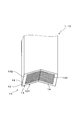
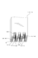
以下、実施例1に係る粒子状物質検出センサについて、図1~図4を参照しながら説明する。図1に示すように、粒子状物質検出センサ1は、内燃機関から排出される排ガスに含まれる粒子状物質の量を検出する素子本体部10を備えている。素子本体部10の先端面には、粒子状物質の一部を堆積させる被堆積部13と、被堆積部13に配置された少なくとも一対の検出電極14とを備えている。粒子状物質検出センサ1は、粒子状物質が被堆積部13上に堆積することによる一対の検出電極14間における電気特性の変化に応じて電気信号の出力を変化させるように構成されている。図1に示されるように、被堆積部13には、被堆積部13の形成された端面から窪んだ捕集凹部131が形成されている。
以下、実施例1に係る粒子状物質検出センサについて、図1~図4を参照しながら説明する。図1に示すように、粒子状物質検出センサ1は、内燃機関から排出される排ガスに含まれる粒子状物質の量を検出する素子本体部10を備えている。素子本体部10の先端面には、粒子状物質の一部を堆積させる被堆積部13と、被堆積部13に配置された少なくとも一対の検出電極14とを備えている。粒子状物質検出センサ1は、粒子状物質が被堆積部13上に堆積することによる一対の検出電極14間における電気特性の変化に応じて電気信号の出力を変化させるように構成されている。図1に示されるように、被堆積部13には、被堆積部13の形成された端面から窪んだ捕集凹部131が形成されている。
以下、実施例1に係る粒子状物質検出センサ1の構造および動作について、さらに詳細に説明する。実施例1に係る粒子状物質検出センサ1は、自動車に搭載された内燃機関から、排気管を通じて排出される排ガスに含まれる粒子状物質を検出するためのものである。粒子状物質検出センサ1によって得られた情報を基に、排ガス浄化装置の故障検知を行う。
図4に示すように、粒子状物質検出センサ1は、素子本体部10と保護カバー2とこれらを保持するハウジング部材(図示省略)とを有している。図1及び図2に示すように、素子本体部10は、排ガス中の粒子状物質を堆積させる被堆積部13を先端面に備えた略棒状をなしている。被堆積部13は、絶縁性材料からなる9つの絶縁部材12と、絶縁部材12の間に配置された8つの検出電極14とを有している。しかしながら、絶縁部材12と検出電極14の数は、特に上記した数に限定されるものではなく、例えば、検出電極14の数は2以上であればよく、絶縁部材12の数は、検出電極14の個数+1個であればよい。なお、検出電極14が複数対設けられている場合には、粒子状物質検出センサ1の出力電流は、各対の検出電極14間に流れる出力電流の総和となる。従って、検出電極14の対が多いほど、検出感度が向上する。
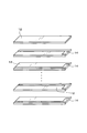
図2及び図3に示すように、絶縁部材12は、アルミナ、ジルコニア、マグネシア、ベリリアなどのセラミック材料を平板状に形成したものである。検出電極14は、焼成前の絶縁部材12の一面に白金ペースト、銅ペースト、銀ペースト等の導電性ペーストを用いたスクリーン印刷により形成されている。検出電極14の形成方法は上記に限定されず、グラビア印刷やインクジェット印刷など電極パターンを形成できる方法であればよい。この検出電極14が形成された絶縁部材12を積層した後、焼成することにより、絶縁部材12と検出電極14とを交互に積層した積層部11が形成される。
積層部11の作製方法は、上記方法に限定されるものではなく、例えば、図2に示す複数の絶縁部材12の個数分の大きさの絶縁部材の上に、複数の検出電極14を形成し、当該検出電極14が形成された絶縁部材を積層した後、切断加工により複数個のピースに分断し、各ピースを焼成することで積層部11を形成してもよい。この形成方法によれば、粒子状物質検出センサ1を複数製造する場合の工程の数を省略することができる。
積層部11においては、正極と負極とが交互に配置されており、隣り合う検出電極14同士が一対の検出電極14を形成している。被堆積部13は、粒子状物質検出センサ1の軸方向における先端側に配置された先端面に、検出電極14の端部近傍を露出して形成されている。
また、被堆積部13が形成された先端面には、先端面から窪んだ捕集凹部131が形成されている。捕集凹部131は、積層部11の積層方向及び軸方向の両方と直交する幅方向において、両端部から中央に向かうにつれて、基端側に向かって傾斜した2つの傾斜面132によって形成されており、この2つの傾斜面132に検出電極14が露出している。図3に示すように、本実施例1に係る粒子状物質検出センサ1の捕集凹部131は、絶縁部材12を積層して焼成した後、先端面に切削加工を施して形成される。
また、捕集凹部131の形成方法は、上記した方法に限定されるものではなく、例えば、検出電極14が形成された積層前の絶縁部材12の状態で打ち抜きや切断加工によって形成してもよく、積層後、焼成前に切断加工あるいは切削加工等によって形成してもよい。ただし、好ましくは、焼成後に形成することで、絶縁部材12と検出電極14との焼成収縮差等によって生じる捕集凹部131のうねりや歪みなどを同時に補正することができる。
上記構成を有する実施例1に係る粒子状物質検出センサ1の被堆積部13において、検出電極14に捕集電圧を印加すると、検出電極14の周囲に電界が形成され、粒子状物質が検出電極14へと引き寄せられる。検出電極14に付着した粒子状物質は、検出電極14の表面を移動し、一対の検出電極14の間に堆積する。そして、被堆積部13に堆積した粒子状物質によって、被堆積部13に露出した一対の検出電極14が導通し、一対の検出電極14の間における電気抵抗値が低下する。検出電極14間の電気抵抗値の変化に伴い、検出電極14間を流れる電気信号としての電流量が変化する。これにより、粒子状物質検出センサ1から出力される電流値が変化する。つまり、粒子状物質検出センサ1から出力される電流値は、被堆積部13における粒子状物質の堆積量に応じて変化するものであり、粒子状物質の堆積量に関する情報を有するものである。この電流値を用いることで被堆積部13における粒子状物質の堆積量を検出することができる。本実施例1に係る粒子状物質検出センサ1において、素子本体部10で検出された電流は、シャント抵抗を備えたコントロールユニット(図示省略)へと出力される。コントロールユニットは、電流値とシャント抵抗の積で算出される電圧を出力する。この電圧が粒子状物質検出センサ1の出力となる。
図4に示すように、保護カバー2は、内側カバー21と、内側カバー21の外周側に配設された外側カバー22とを有している。内側カバー21は、素子本体部10を囲む円筒状の内側壁部211と、内側壁部211の先端に形成された内側底部212とを有している。内側カバー21は、ハウジング部材の先端面(図示省略)にかしめて固定されている。
内側壁部211には、内側導入孔214が形成されている。内側導入孔214の内径は円形をなしており、軸方向から見たとき、内側壁部211の円周方向に等間隔となるように形成されている。また、内側導入孔214は、素子本体部10の被堆積部13よりも先端側の位置に形成されている。内側底部212の中心には、軸方向に貫通形成された内側排出孔215が形成されている。
外側カバー22は、保護カバー2を囲む円筒状の外側壁部221と、外側壁部221の先端に形成された外側底部222とを有している。外側カバー22は、ハウジング部材の先端面に内側カバー21と共にかしめて固定されている。
外側壁部221には、外側導入孔224が形成されている。外側導入孔224の内径は円形をなしており、軸方向から見たとき、外側壁部221の円周方向に等間隔となるように形成されると共に、各外側導入孔224と各内側導入孔214とは、径方向に重なる位置に形成されている。また、外側導入孔224は、内側導入孔214よりも先端側の位置に形成されている。外側底部222の中心には、軸方向に貫通形成された外側排出孔225が形成されている。
本実施例1に係る粒子状物質検出センサ1においては、複数の外側導入孔224から導入された排ガスGは、導入方向を変化させた後、内側導入孔214から内側カバー21の内側に導入されるよう構成されている。すなわち、排気管内を流通する排ガスの流通方向に沿うように外側導入孔224から外側カバー22の内側へと流入した排ガスは、内側カバー21の内側壁部211に衝突することで、内側壁部211に沿うように導入方向を変化させる。そして、内側カバー21と外側カバー22との間の空隙を流通して、内側導入孔214から内側カバー21の内側へと流入する。このとき、内側カバー21内に流入する排ガスの流れの中に、被堆積部13を配置しており、被堆積部13に向かう排ガスの流れが形成されている。
次に、本実施例1に係る粒子状物質検出センサの作用効果について説明する。粒子状物質検出センサ1は、上記説明した構造を有する捕集凹部131を備えている。そのため、被堆積部13に衝突する粒子状物質を効率よく捕集することができる。すなわち、捕集凹部131内に入り込んだ粒子状物質が、捕集凹部131の内周面に衝突し跳ね返ったとしても、捕集凹部131は素子本体部10の端面から窪むように形成されていることから、跳ね返った粒子状物質が再度、捕集凹部131の内周面に衝突しやすい。このとき、粒子状物質の衝突速度は、最初に捕集凹部131に衝突した際に減速する。そのため、跳ね返った粒子状物質が再度捕集凹部131の内周面に衝突する際には、捕集凹部131の内周面に付着しやすい。したがって、捕集凹部131を設けることにより被堆積部
13における捕集効率を向上させることができる。
13における捕集効率を向上させることができる。
また、被堆積部13の周囲を覆う内側カバー21や外側カバー22を備えた保護カバー2を有している。この保護カバー2には、排ガスを導入するための導入孔が貫通形成されており、導入孔を通じて排ガスを導入することにより、捕集凹部131に向かう排ガスの流れを形成するよう構成されている。そのため、被堆積部13に粒子状物質を含む排ガスを効率良く供給することができる。また、排ガスの流通方向が決まるため、この流通方向に合わせて捕集凹部131を形成することにより、さらに捕集効率を向上させることができる。
また、複数の検出電極14と電気絶縁性を有する複数の絶縁部材12とを交互に積層した積層部11を有しており、積層部11の先端面に、被堆積部13及び検出電極14が形成されている。そのため、検出電極14間の距離を容易に短縮し、検出感度が優れた粒子状物質検出センサ1を容易に製造することができる。
以上説明したように、本実施例1によれば、粒子状物質の検出感度を向上させることができる粒子状物質検出センサ1を提供することができる。
(実施例2)
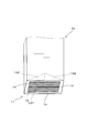
以下に、実施例2に係る粒子状物質検出センサ1-1について、図5を参照しながら説明する。図5に示すように、実施例2に係る粒子状物質検出センサ1-1の構造は、実施例1の粒子状物質検出センサ1における構造を一部変更した例を示すものである。本実施例2に係る粒子状物質検出センサ1-1において、被堆積部13-1に形成された捕集凹部131-1は、積層方向と直交する断面における断面形状が円弧状となる曲面をなしている。その他の構成は実施例1と同様である。尚、本実施例2に係る粒子状物質検出センサ1-1で用いた符号のうち、実施例1に係る粒子状物質検出センサ1において用いた符号と同一のものは、特に示さない限り、実施例1に係る粒子状物質検出センサ1と同様の構成要素等を示すものである。
以下に、実施例2に係る粒子状物質検出センサ1-1について、図5を参照しながら説明する。図5に示すように、実施例2に係る粒子状物質検出センサ1-1の構造は、実施例1の粒子状物質検出センサ1における構造を一部変更した例を示すものである。本実施例2に係る粒子状物質検出センサ1-1において、被堆積部13-1に形成された捕集凹部131-1は、積層方向と直交する断面における断面形状が円弧状となる曲面をなしている。その他の構成は実施例1と同様である。尚、本実施例2に係る粒子状物質検出センサ1-1で用いた符号のうち、実施例1に係る粒子状物質検出センサ1において用いた符号と同一のものは、特に示さない限り、実施例1に係る粒子状物質検出センサ1と同様の構成要素等を示すものである。
捕集凹部131-1は、一対の検出電極14の並び方向と直交する平面における断面形状が円弧状をなしている。円弧状の断面を有する捕集凹部131-1においては、その内周面の角度が徐々に変化していく。そのため、複数の方向から衝突する粒子状物質を効率良く捕集することができる。これにより、粒子状物質の検出感度を一層向上させることができる。尚、本実施例2に係る粒子状物質検出センサ1-1の説明および図5で用いた符号のうち、実施例1に係る粒子状物質検出センサ1で用いた符号と同一のものは、特に示さない限り、実施例1のものと同様の構成および動作を有するものである。
(実施例3)
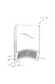
以下に、実施例3に係る粒子状物質検出センサ1-2について、図6を参照しながら説明する。図6に示すように、実施例3に係る粒子状物質検出センサ1-2は、実施例1に係る粒子状物質検出センサ1における構造を一部変更した例を示すものである。実施例3に係る粒子状物質検出センサ1-2において、被堆積部13-2には、3つの捕集凹部131-2が形成されている。各捕集凹部131-2は、先端面から基端側に窪んだ位置に形成された凹部底面133と、先端面と凹部底面133とを繋ぐように形成された一対の凹部側面134とを有している。
以下に、実施例3に係る粒子状物質検出センサ1-2について、図6を参照しながら説明する。図6に示すように、実施例3に係る粒子状物質検出センサ1-2は、実施例1に係る粒子状物質検出センサ1における構造を一部変更した例を示すものである。実施例3に係る粒子状物質検出センサ1-2において、被堆積部13-2には、3つの捕集凹部131-2が形成されている。各捕集凹部131-2は、先端面から基端側に窪んだ位置に形成された凹部底面133と、先端面と凹部底面133とを繋ぐように形成された一対の凹部側面134とを有している。
検出電極14は、捕集凹部131-2の内側に形成された内側電極部142と、捕集凹部131-2以外の被堆積部13-2に形成された外側電極部141とを有している。本実施例3に係る粒子状物質検出センサ1-2において、内側電極部142は、素子本体部10の先端面(被堆積部13)に設けられた捕集凹部131-2の内側に形成されている。内側電極部142は、捕集凹部131-2の凹部底面133及び一対の凹部側面134に形成されている。
また、外側電極部141は、素子本体部10の先端面(被堆積部13-2)における、捕集凹部131を設けていない位置に形成されている。すなわち、外側電極部141は、3つの捕集凹部131-2のうち、隣り合う捕集凹部131-2の間、および、両端の捕集凹部131-2の外側に存在する、素子本体部10の先端面に形成されている。内側電極部142と外側電極部141とは電気的に接続されている。
その他の構成は、実施例1に係る粒子状物質検出センサ1の構成と同様である。尚、本実施例3に係る粒子状物質検出センサ1-2の説明および図6で用いた符号のうち、実施例1に係る粒子状物質検出センサ1で用いた符号と同一のものは、特に示さない限り、実施例1のものと同様の構成および動作を有するものである。
本実施例3に係る例の粒子状物質検出センサ1-2は、捕集凹部131-2の外側において、粒子状物質を検出すると共に、粒子状物質の捕集効率が高い捕集凹部131-2内に内側電極部142を形成することにより、検出感度を向上させることができる。
また、被堆積部13-2に、複数の捕集凹部131-2を形成することで、粒子状物質における捕集効率を向上し、その捕集効率をより向上させることができる。例えば、図6では3つの捕集凹部131-2が形成されている。その他、実施例1に係る粒子状物質検出センサ1と同様の作用効果を有する。
また、実施例1~実施例3の粒子状物質検出センサ1において、捕集凹部131,131-1,131-2は、積層方向において一様な断面形状をなしているが、例えば、粒子状物質検出センサ1,1-1,1-2の中心軸を中心として、断面形状を回転させた略椀状の捕集凹部131,131-1,131-2をそれぞれ形成してもよい。
また、実施例1~実施例3の粒子状物質検出センサ1,1-1,1-2において、捕集凹部131,131-1,131-2の端縁の外側角部、及び捕集凹部131,131-1,131-2内の内側角部に、R面、C面等の面取り加工を施すことが好ましい。例えば、外側角部又は内側角部にR面を設ける場合、その面取り寸法を、R0.01~R1.0(すなわちR面取り寸法0.01mm~1.0mm)とすることができる。また、例えば、外側角部又は内側角部にC面を設ける場合、その面取り寸法を、C0.01~C1.0(すなわちC面取り寸法0.01mm~1.0mm)とすることができる。これにより、衝突物や急激な温度変化による応力への耐性を向上させることができる。また、望ましくは焼成前に上記の加工を行うことで、焼成時における割れ、欠け等を抑制することができる。
(比較試験)本比較試験においては、実施例1~実施例3の粒子状物質検出センサ1,1-1,1-2と、捕集凹部131,131-1,131-2とが形成されていない従来の粒子状物質検出センサとの検出感度を比較した。従来の粒子状物質検出センサとしては、実施例1において、捕集凹部131を形成する前の状態の粒子状物質検出センサ(図3参照)を用いている。すなわち、従来の粒子状物質検出センサは、被堆積部が軸方向に直交する平坦面によって形成されている。尚、従来の粒子状物質検出センサは、捕集凹部131が形成されていないことを除いて、実施例1の粒子状物質検出センサ1と同様の構造を有している。
比較試験の試験条件は、粒子状物質近傍における温度が200℃、粒子状物質濃度が3mg/m3の排ガスを、流速20m/s及び流速50m/sにて流通させた際の不感質量を計測した。尚、不感質量は、粒子状物質検出センサ1において、出力信号が変化するまでの間に排出される粒子状物質の総量を示すものである。

表1は、比較試験の結果を示すものである。表1において、比較例で示される従来の粒子状物質検出センサにおける不感質量は、流速20m/sにおいては34mgとなり、流速50m/sにおいては50mgであった。また、表1において、実施例1の粒子状物質検出センサ1における不感質量は、流速20m/sにおいては28mgとなり、流速50m/sにおいては35mgであった。このように、実施例1の粒子状物質検出センサ1は、排ガスの流速が20m/s及び50m/sのいずれにおいても、比較例で示される従来の粒子状物質検出センサよりも不感質量が少なくなることが確認された。また、実施例1の粒子状物質検出センサ1は、排ガスの流速を変化させた際の不感質量の変化量も従来の粒子状物質検出センサよりも小さいことが確認された。これにより、実施例1の粒子状物質検出センサ1においては、排ガスの流速が増大した場合にも、被堆積部13における粒子状物質の跳ね返りを防止し、捕集効率を向上させることができる。
また、表1に示すように、実施例2に係る粒子状物質検出センサ1-1における不感質量は、実施例1の粒子状物質検出センサ1における不感質量よりも少なく、実施例3に係る粒子状物質検出センサ1-2における不感質量は、実施例2の粒子状物質検出センサ1-1における不感質量よりも更に少ないことがわかった。この傾向は、排ガスの流速が20m/sである場合においても50m/sである場合においても同様である。さらに、排ガスの流速を変化させた際の不感質量の変化量についても、実施例1よりも実施例2に係る粒子状物質検出センサ1-2の方が、また、実施例2に係る粒子状物質検出センサ1-1よりも、実施例3に係る粒子状物質検出センサ1-2の方が小さいことがわかった。
以上の結果から、実施例1~3の粒子状物質検出センサ1,1-1,1-2は、従来の粒子状物質検出センサに比べて、検出感度に優れていることが分かる。そして、実施例1よりも実施例2の粒子状物質検出センサ1-1の方が、検出感度に優れ、さらに実施例2よりも実施例3の粒子状物質検出センサ1-2の方が、検出感度に優れていることがわかった。
1,1-1,1-2 粒子状物質検出センサ、10 素子本体部、13,13-1,13-2 被堆積部、131,131-1,131-2 捕集凹部、14 検出電極。
Claims (6)
- 内燃機関から排出される排ガスに含まれる粒子状物質の量を検出する素子本体部(10)を備えており、
該素子本体部(10)の端面の1つには、上記粒子状物質の一部を堆積させる被堆積部(13,13-1,13-2)と、該被堆積部(13,13-1,13-2)に配置された少なくとも一対の検出電極(14)とを備え、
上記粒子状物質が上記被堆積部(13,13-1,13-2)上に堆積した量に応じて、上記一対の検出電極(14)間における電気特性の変化に応じて変化する電気信号を出力するように構成され、
上記被堆積部(13,13-1,13-2)には、該被堆積部(13,13-1,13-2)が形成された端面から、窪んだ形状の捕集凹部(131,131-1,131-2)が形成されていることを特徴とする粒子状物質検出センサ(1,1-1,1-2)。 - 上記検出電極(14)は、上記捕集凹部(131-2)の内側に形成された内側電極部(142)と、上記捕集凹部(131-2)以外の上記被堆積部(13-2)に形成された外側電極部(141)とを有しており、該外側電極部(141)と上記内側電極部(142)とは、電気的に接続されていることを特徴とする請求項1に記載の粒子状物質検出センサ(1)。
- 上記被堆積部(13,13-1,13-2)の周囲を覆う保護カバー(2)をさらに有しており、該保護カバー(2)には、排ガスを導入するための導入孔(214,224)が貫通形成されており、該導入孔(214,224)を通じて排ガスを導入することにより、上記捕集凹部(131,131-1,131-2)に向かう排ガスの流れを形成するよう構成されていることを特徴とする請求項1又は2に記載の粒子状物質検出センサ(1)。
- 上記捕集凹部(131-1)は、円弧状の曲面をなしていることを特徴とする請求項1~3のいずれか一項に記載の粒子状物質検出センサ(1-1)。
- 上記被堆積部(13-2)には、複数の上記捕集凹部(131-2)が形成されていることを特徴とする請求項1~4のいずれか一項に記載の粒子状物質検出センサ(1-2)。
- 複数の上記検出電極(14)と電気絶縁性を有する複数の絶縁部材(12)とを交互に積層した積層部(11)を有しており、該積層部(11)の端面に、上記被堆積部(13,13-1,13-2)及び上記検出電極(14)が形成されていることを特徴とする請求項1~5のいずれか一項に記載の粒子状物質検出センサ(1)。
Priority Applications (3)
| Application Number | Priority Date | Filing Date | Title |
|---|---|---|---|
| CN201680024709.2A CN107532988B (zh) | 2015-04-28 | 2016-04-12 | 颗粒状物质检测传感器 |
| US15/569,510 US10337974B2 (en) | 2015-04-28 | 2016-04-12 | Particulate matter detection sensor |
| DE112016001991.2T DE112016001991T5 (de) | 2015-04-28 | 2016-04-12 | Feinstauberfassungssensor |
Applications Claiming Priority (2)
| Application Number | Priority Date | Filing Date | Title |
|---|---|---|---|
| JP2015091242A JP6441161B2 (ja) | 2015-04-28 | 2015-04-28 | 粒子状物質検出センサ |
| JP2015-091242 | 2015-04-28 |
Publications (1)
| Publication Number | Publication Date |
|---|---|
| WO2016175022A1 true WO2016175022A1 (ja) | 2016-11-03 |
Family
ID=57199243
Family Applications (1)
| Application Number | Title | Priority Date | Filing Date |
|---|---|---|---|
| PCT/JP2016/061749 Ceased WO2016175022A1 (ja) | 2015-04-28 | 2016-04-12 | 粒子状物質検出センサ |
Country Status (5)
| Country | Link |
|---|---|
| US (1) | US10337974B2 (ja) |
| JP (1) | JP6441161B2 (ja) |
| CN (1) | CN107532988B (ja) |
| DE (1) | DE112016001991T5 (ja) |
| WO (1) | WO2016175022A1 (ja) |
Families Citing this family (3)
| Publication number | Priority date | Publication date | Assignee | Title |
|---|---|---|---|---|
| JP6547274B2 (ja) * | 2014-10-20 | 2019-07-24 | 株式会社デンソー | 粒子状物質検出センサ |
| JP6425993B2 (ja) * | 2014-12-23 | 2018-11-21 | 株式会社Soken | 粒子状物質検出素子 |
| JP7151542B2 (ja) * | 2019-02-21 | 2022-10-12 | 株式会社デンソー | センサ装置 |
Citations (5)
| Publication number | Priority date | Publication date | Assignee | Title |
|---|---|---|---|---|
| JP2008051715A (ja) * | 2006-08-25 | 2008-03-06 | Yoshiharu Nagamatsu | 無線タグ型センサ |
| JP2010014615A (ja) * | 2008-07-04 | 2010-01-21 | Ngk Insulators Ltd | 粒子状物質検出装置 |
| JP2012058015A (ja) * | 2010-09-07 | 2012-03-22 | Ngk Insulators Ltd | 粒子状物質検出装置 |
| JP2012078130A (ja) * | 2010-09-30 | 2012-04-19 | Denso Corp | 粒子状物質検出センサおよびその製造方法 |
| JP2012150028A (ja) * | 2011-01-20 | 2012-08-09 | Denso Corp | 検出装置 |
Family Cites Families (40)
| Publication number | Priority date | Publication date | Assignee | Title |
|---|---|---|---|---|
| US4656832A (en) * | 1982-09-30 | 1987-04-14 | Nippondenso Co., Ltd. | Detector for particulate density and filter with detector for particulate density |
| JPS59197847A (ja) | 1983-04-25 | 1984-11-09 | Ngk Spark Plug Co Ltd | スモーク濃度センサ |
| JPS60196659A (ja) | 1984-03-21 | 1985-10-05 | Hitachi Ltd | センサ用抵抗測定電極 |
| DE19959871A1 (de) * | 1999-12-10 | 2001-06-28 | Heraeus Electro Nite Int | Sensor und Verfahren zur Ermittlung von Ruß-Konzentrationen |
| JP4030351B2 (ja) * | 2001-06-20 | 2008-01-09 | 株式会社デンソー | ガスセンサ |
| US6634210B1 (en) * | 2002-04-17 | 2003-10-21 | Delphi Technologies, Inc. | Particulate sensor system |
| DE102004028997A1 (de) * | 2004-06-16 | 2006-01-05 | Robert Bosch Gmbh | Verfahren zur Beeinflussung der Russanlagerung auf Sensoren |
| DE102005030134A1 (de) * | 2005-06-28 | 2007-01-04 | Siemens Ag | Sensor und Betriebsverfahren zur Detektion von Ruß |
| DE102005053120A1 (de) * | 2005-11-08 | 2007-05-10 | Robert Bosch Gmbh | Sensorelement für Gassensoren und Verfahren zum Betrieb desselben |
| DE102006047927A1 (de) | 2006-10-10 | 2008-04-17 | Robert Bosch Gmbh | Sensor zur resistiven Bestimmung von Konzentrationen leitfähiger Partikel in Gasströmen |
| JP5081897B2 (ja) * | 2007-03-15 | 2012-11-28 | 日本碍子株式会社 | 粒子状物質検出装置及び粒子状物質検出方法 |
| JP2009002890A (ja) * | 2007-06-25 | 2009-01-08 | Denso Corp | ガスセンサ |
| DE102007047081A1 (de) * | 2007-10-01 | 2009-04-02 | Robert Bosch Gmbh | Verfahren zur Detektion eines Vergiftungsgrads eines Partikelsensors und Partikelsensor |
| US7914603B2 (en) * | 2008-06-26 | 2011-03-29 | Mks Instruments, Inc. | Particle trap for a plasma source |
| US8176768B2 (en) * | 2008-07-04 | 2012-05-15 | Ngk Insulators, Ltd. | Particulate matter detection device |
| JP2011080781A (ja) * | 2009-10-05 | 2011-04-21 | Nippon Soken Inc | パティキュレート検出素子及びこれを用いたパティキュレート検出センサ |
| DE102009058260A1 (de) * | 2009-12-14 | 2011-06-16 | Continental Automotive Gmbh | Rußsensor |
| WO2012077182A1 (ja) * | 2010-12-07 | 2012-06-14 | トヨタ自動車株式会社 | 内燃機関の粒子状物質検出装置 |
| DE102010055478A1 (de) * | 2010-12-22 | 2012-06-28 | Continental Automotive Gmbh | Verfahren zum Betreiben eines Rußsensors |
| JP5547126B2 (ja) * | 2011-05-11 | 2014-07-09 | 日本特殊陶業株式会社 | 微粒子検知システム |
| FR2978493B1 (fr) * | 2011-07-28 | 2013-09-06 | Electricfil Automotive | Procede et dispositif de mesure de la concentration de suies dans un gaz d'echappement, notamment d'un moteur a combustion interne |
| WO2013030930A1 (ja) * | 2011-08-29 | 2013-03-07 | トヨタ自動車株式会社 | 微粒子センサ及び微粒子センサの製造方法 |
| CN103946492B (zh) * | 2011-11-15 | 2016-11-23 | 丰田自动车株式会社 | 内燃机的控制装置及控制方法 |
| JP5895006B2 (ja) * | 2012-01-18 | 2016-03-30 | 日立オートモティブシステムズ株式会社 | 熱式流量計 |
| JP5634433B2 (ja) * | 2012-04-27 | 2014-12-03 | 株式会社日本自動車部品総合研究所 | 粒子状物質検出素子とその製造方法、並びに、粒子状物質検出センサ |
| JP5682637B2 (ja) * | 2012-05-17 | 2015-03-11 | 株式会社デンソー | ガスセンサ |
| DE102012210525A1 (de) * | 2012-06-21 | 2013-12-24 | Robert Bosch Gmbh | Verfahren zur Funktionskontrolle eines Sensors zur Detektion von Teilchen und Sensor zur Detektion von Teilchen |
| DE102013202980A1 (de) * | 2013-02-22 | 2014-08-28 | Robert Bosch Gmbh | Verfahren und Vorrichtung zur Regeneration eines Partikelsensors |
| JP6228018B2 (ja) * | 2014-01-10 | 2017-11-08 | 株式会社Soken | 粒子状物質検出素子、粒子状物質検出センサ並びに粒子状物質検出素子の製造方法 |
| JP6329820B2 (ja) * | 2014-06-16 | 2018-05-23 | 株式会社Soken | 粒子状物質検出センサ |
| JP6380278B2 (ja) * | 2014-09-16 | 2018-08-29 | 株式会社デンソー | ガスセンサ |
| JP6547274B2 (ja) * | 2014-10-20 | 2019-07-24 | 株式会社デンソー | 粒子状物質検出センサ |
| JP2016090439A (ja) * | 2014-11-06 | 2016-05-23 | 株式会社日本自動車部品総合研究所 | 粒子状物質検出素子及び粒子状物質検出センサ |
| JP6425993B2 (ja) * | 2014-12-23 | 2018-11-21 | 株式会社Soken | 粒子状物質検出素子 |
| JP6514336B2 (ja) * | 2014-12-23 | 2019-05-15 | ヘレウス センサー テクノロジー ゲゼルシャフト ミット ベシュレンクテル ハフツング | 導電性及び/又は分極性粒子を検出するセンサ、センサシステム、センサを作動させる方法、このタイプのセンサを製造する方法及びこのタイプのセンサの使用 |
| JP6536507B2 (ja) * | 2015-09-15 | 2019-07-03 | 株式会社デンソー | 粒子状物質検出センサ |
| US10557784B2 (en) * | 2015-11-20 | 2020-02-11 | Ford Global Technologies, Llc | Method and system for exhaust particulate matter sensing |
| KR101755469B1 (ko) * | 2015-12-08 | 2017-07-07 | 현대자동차 주식회사 | 미세 물질 측정 센서 |
| KR101724499B1 (ko) * | 2015-12-11 | 2017-04-07 | 현대자동차 주식회사 | 입자상 물질 센서 및 이를 이용한 측정방법 |
| JP6977366B2 (ja) * | 2017-07-27 | 2021-12-08 | 株式会社デンソー | 粒子状物質検出センサ |
-
2015
- 2015-04-28 JP JP2015091242A patent/JP6441161B2/ja not_active Expired - Fee Related
-
2016
- 2016-04-12 DE DE112016001991.2T patent/DE112016001991T5/de not_active Withdrawn
- 2016-04-12 WO PCT/JP2016/061749 patent/WO2016175022A1/ja not_active Ceased
- 2016-04-12 US US15/569,510 patent/US10337974B2/en active Active
- 2016-04-12 CN CN201680024709.2A patent/CN107532988B/zh not_active Expired - Fee Related
Patent Citations (5)
| Publication number | Priority date | Publication date | Assignee | Title |
|---|---|---|---|---|
| JP2008051715A (ja) * | 2006-08-25 | 2008-03-06 | Yoshiharu Nagamatsu | 無線タグ型センサ |
| JP2010014615A (ja) * | 2008-07-04 | 2010-01-21 | Ngk Insulators Ltd | 粒子状物質検出装置 |
| JP2012058015A (ja) * | 2010-09-07 | 2012-03-22 | Ngk Insulators Ltd | 粒子状物質検出装置 |
| JP2012078130A (ja) * | 2010-09-30 | 2012-04-19 | Denso Corp | 粒子状物質検出センサおよびその製造方法 |
| JP2012150028A (ja) * | 2011-01-20 | 2012-08-09 | Denso Corp | 検出装置 |
Also Published As
| Publication number | Publication date |
|---|---|
| JP2016206128A (ja) | 2016-12-08 |
| DE112016001991T5 (de) | 2018-01-11 |
| CN107532988B (zh) | 2020-03-10 |
| CN107532988A (zh) | 2018-01-02 |
| JP6441161B2 (ja) | 2018-12-19 |
| US10337974B2 (en) | 2019-07-02 |
| US20180266934A1 (en) | 2018-09-20 |
Similar Documents
| Publication | Publication Date | Title |
|---|---|---|
| JP6536507B2 (ja) | 粒子状物質検出センサ | |
| JP5542006B2 (ja) | 粒子状物質検出装置 | |
| JP6425960B2 (ja) | 積層型のガスセンサ素子、ガスセンサ、及びその製造方法 | |
| WO2015194363A1 (ja) | 粒子状物質検出センサ | |
| JP7288783B2 (ja) | センサ素子及びガスセンサ | |
| WO2016175022A1 (ja) | 粒子状物質検出センサ | |
| WO2016072146A1 (ja) | 粒子状物質検出素子及び粒子状物質検出センサ | |
| WO2016080120A1 (ja) | 粒子状物質検出センサ | |
| WO2017090587A1 (ja) | 粒子状物質の測定装置用部品およびその製造方法 | |
| US10591431B2 (en) | Sensor element | |
| JP6425993B2 (ja) | 粒子状物質検出素子 | |
| EP3460430B1 (en) | Temperature sensor and temperature measuring device | |
| WO2016185841A1 (ja) | 粒子状物質検出センサ | |
| CN109073479B (zh) | 传感器基板以及传感器装置 | |
| JP4780686B2 (ja) | ガスセンサ素子の製造方法及びガスセンサの製造方法 | |
| US20210199617A1 (en) | Sensor element for gas sensor | |
| JP6542913B2 (ja) | 粒子状物質の測定装置用部品 | |
| JP6511304B2 (ja) | 粒子状物質検出センサ | |
| JP4618681B2 (ja) | ガスセンサ素子及びガスセンサ | |
| CN111033220A (zh) | 微粒检测元件及微粒检测器 | |
| JP6435198B2 (ja) | 粒子状物質検出センサ | |
| JPWO2017115617A1 (ja) | 粒子状物質の測定装置用部品 | |
| WO2017047606A1 (ja) | 粒子状物質検出センサ |
Legal Events
| Date | Code | Title | Description |
|---|---|---|---|
| 121 | Ep: the epo has been informed by wipo that ep was designated in this application |
Ref document number: 16786299 Country of ref document: EP Kind code of ref document: A1 |
|
| WWE | Wipo information: entry into national phase |
Ref document number: 15569510 Country of ref document: US |
|
| WWE | Wipo information: entry into national phase |
Ref document number: 112016001991 Country of ref document: DE |
|
| 122 | Ep: pct application non-entry in european phase |
Ref document number: 16786299 Country of ref document: EP Kind code of ref document: A1 |