WO2016171015A1 - 流量制御弁 - Google Patents
流量制御弁 Download PDFInfo
- Publication number
- WO2016171015A1 WO2016171015A1 PCT/JP2016/061590 JP2016061590W WO2016171015A1 WO 2016171015 A1 WO2016171015 A1 WO 2016171015A1 JP 2016061590 W JP2016061590 W JP 2016061590W WO 2016171015 A1 WO2016171015 A1 WO 2016171015A1
- Authority
- WO
- WIPO (PCT)
- Prior art keywords
- passage
- control valve
- tank
- valve
- port
- Prior art date
- Legal status (The legal status is an assumption and is not a legal conclusion. Google has not performed a legal analysis and makes no representation as to the accuracy of the status listed.)
- Ceased
Links
Images



Classifications
-
- F—MECHANICAL ENGINEERING; LIGHTING; HEATING; WEAPONS; BLASTING
- F15—FLUID-PRESSURE ACTUATORS; HYDRAULICS OR PNEUMATICS IN GENERAL
- F15B—SYSTEMS ACTING BY MEANS OF FLUIDS IN GENERAL; FLUID-PRESSURE ACTUATORS, e.g. SERVOMOTORS; DETAILS OF FLUID-PRESSURE SYSTEMS, NOT OTHERWISE PROVIDED FOR
- F15B11/00—Servomotor systems without provision for follow-up action; Circuits therefor
- F15B11/02—Systems essentially incorporating special features for controlling the speed or actuating force of an output member
- F15B11/024—Systems essentially incorporating special features for controlling the speed or actuating force of an output member by means of differential connection of the servomotor lines, e.g. regenerative circuits
-
- F—MECHANICAL ENGINEERING; LIGHTING; HEATING; WEAPONS; BLASTING
- F15—FLUID-PRESSURE ACTUATORS; HYDRAULICS OR PNEUMATICS IN GENERAL
- F15B—SYSTEMS ACTING BY MEANS OF FLUIDS IN GENERAL; FLUID-PRESSURE ACTUATORS, e.g. SERVOMOTORS; DETAILS OF FLUID-PRESSURE SYSTEMS, NOT OTHERWISE PROVIDED FOR
- F15B13/00—Details of servomotor systems ; Valves for servomotor systems
- F15B13/02—Fluid distribution or supply devices characterised by their adaptation to the control of servomotors
- F15B13/021—Valves for interconnecting the fluid chambers of an actuator
-
- F—MECHANICAL ENGINEERING; LIGHTING; HEATING; WEAPONS; BLASTING
- F15—FLUID-PRESSURE ACTUATORS; HYDRAULICS OR PNEUMATICS IN GENERAL
- F15B—SYSTEMS ACTING BY MEANS OF FLUIDS IN GENERAL; FLUID-PRESSURE ACTUATORS, e.g. SERVOMOTORS; DETAILS OF FLUID-PRESSURE SYSTEMS, NOT OTHERWISE PROVIDED FOR
- F15B11/00—Servomotor systems without provision for follow-up action; Circuits therefor
-
- F—MECHANICAL ENGINEERING; LIGHTING; HEATING; WEAPONS; BLASTING
- F15—FLUID-PRESSURE ACTUATORS; HYDRAULICS OR PNEUMATICS IN GENERAL
- F15B—SYSTEMS ACTING BY MEANS OF FLUIDS IN GENERAL; FLUID-PRESSURE ACTUATORS, e.g. SERVOMOTORS; DETAILS OF FLUID-PRESSURE SYSTEMS, NOT OTHERWISE PROVIDED FOR
- F15B11/00—Servomotor systems without provision for follow-up action; Circuits therefor
- F15B11/16—Servomotor systems without provision for follow-up action; Circuits therefor with two or more servomotors
- F15B11/17—Servomotor systems without provision for follow-up action; Circuits therefor with two or more servomotors using two or more pumps
-
- F—MECHANICAL ENGINEERING; LIGHTING; HEATING; WEAPONS; BLASTING
- F15—FLUID-PRESSURE ACTUATORS; HYDRAULICS OR PNEUMATICS IN GENERAL
- F15B—SYSTEMS ACTING BY MEANS OF FLUIDS IN GENERAL; FLUID-PRESSURE ACTUATORS, e.g. SERVOMOTORS; DETAILS OF FLUID-PRESSURE SYSTEMS, NOT OTHERWISE PROVIDED FOR
- F15B21/00—Common features of fluid actuator systems; Fluid-pressure actuator systems or details thereof, not covered by any other group of this subclass
- F15B21/14—Energy-recuperation means
-
- F—MECHANICAL ENGINEERING; LIGHTING; HEATING; WEAPONS; BLASTING
- F16—ENGINEERING ELEMENTS AND UNITS; GENERAL MEASURES FOR PRODUCING AND MAINTAINING EFFECTIVE FUNCTIONING OF MACHINES OR INSTALLATIONS; THERMAL INSULATION IN GENERAL
- F16K—VALVES; TAPS; COCKS; ACTUATING-FLOATS; DEVICES FOR VENTING OR AERATING
- F16K27/00—Construction of housing; Use of materials therefor
- F16K27/04—Construction of housing; Use of materials therefor of sliding valves
-
- E—FIXED CONSTRUCTIONS
- E02—HYDRAULIC ENGINEERING; FOUNDATIONS; SOIL SHIFTING
- E02F—DREDGING; SOIL-SHIFTING
- E02F9/00—Component parts of dredgers or soil-shifting machines, not restricted to one of the kinds covered by groups E02F3/00 - E02F7/00
- E02F9/20—Drives; Control devices
- E02F9/22—Hydraulic or pneumatic drives
- E02F9/2278—Hydraulic circuits
- E02F9/2292—Systems with two or more pumps
-
- F—MECHANICAL ENGINEERING; LIGHTING; HEATING; WEAPONS; BLASTING
- F15—FLUID-PRESSURE ACTUATORS; HYDRAULICS OR PNEUMATICS IN GENERAL
- F15B—SYSTEMS ACTING BY MEANS OF FLUIDS IN GENERAL; FLUID-PRESSURE ACTUATORS, e.g. SERVOMOTORS; DETAILS OF FLUID-PRESSURE SYSTEMS, NOT OTHERWISE PROVIDED FOR
- F15B2211/00—Circuits for servomotor systems
- F15B2211/20—Fluid pressure source, e.g. accumulator or variable axial piston pump
- F15B2211/205—Systems with pumps
- F15B2211/20576—Systems with pumps with multiple pumps
-
- F—MECHANICAL ENGINEERING; LIGHTING; HEATING; WEAPONS; BLASTING
- F15—FLUID-PRESSURE ACTUATORS; HYDRAULICS OR PNEUMATICS IN GENERAL
- F15B—SYSTEMS ACTING BY MEANS OF FLUIDS IN GENERAL; FLUID-PRESSURE ACTUATORS, e.g. SERVOMOTORS; DETAILS OF FLUID-PRESSURE SYSTEMS, NOT OTHERWISE PROVIDED FOR
- F15B2211/00—Circuits for servomotor systems
- F15B2211/30—Directional control
- F15B2211/305—Directional control characterised by the type of valves
- F15B2211/3056—Assemblies of multiple valves
- F15B2211/30565—Assemblies of multiple valves having multiple valves for a single output member, e.g. for creating higher valve function by use of multiple valves like two 2/2-valves replacing a 5/3-valve
-
- F—MECHANICAL ENGINEERING; LIGHTING; HEATING; WEAPONS; BLASTING
- F15—FLUID-PRESSURE ACTUATORS; HYDRAULICS OR PNEUMATICS IN GENERAL
- F15B—SYSTEMS ACTING BY MEANS OF FLUIDS IN GENERAL; FLUID-PRESSURE ACTUATORS, e.g. SERVOMOTORS; DETAILS OF FLUID-PRESSURE SYSTEMS, NOT OTHERWISE PROVIDED FOR
- F15B2211/00—Circuits for servomotor systems
- F15B2211/30—Directional control
- F15B2211/305—Directional control characterised by the type of valves
- F15B2211/3056—Assemblies of multiple valves
- F15B2211/3059—Assemblies of multiple valves having multiple valves for multiple output members
- F15B2211/30595—Assemblies of multiple valves having multiple valves for multiple output members with additional valves between the groups of valves for multiple output members
-
- F—MECHANICAL ENGINEERING; LIGHTING; HEATING; WEAPONS; BLASTING
- F15—FLUID-PRESSURE ACTUATORS; HYDRAULICS OR PNEUMATICS IN GENERAL
- F15B—SYSTEMS ACTING BY MEANS OF FLUIDS IN GENERAL; FLUID-PRESSURE ACTUATORS, e.g. SERVOMOTORS; DETAILS OF FLUID-PRESSURE SYSTEMS, NOT OTHERWISE PROVIDED FOR
- F15B2211/00—Circuits for servomotor systems
- F15B2211/30—Directional control
- F15B2211/31—Directional control characterised by the positions of the valve element
- F15B2211/3105—Neutral or centre positions
- F15B2211/3116—Neutral or centre positions the pump port being open in the centre position, e.g. so-called open centre
-
- F—MECHANICAL ENGINEERING; LIGHTING; HEATING; WEAPONS; BLASTING
- F15—FLUID-PRESSURE ACTUATORS; HYDRAULICS OR PNEUMATICS IN GENERAL
- F15B—SYSTEMS ACTING BY MEANS OF FLUIDS IN GENERAL; FLUID-PRESSURE ACTUATORS, e.g. SERVOMOTORS; DETAILS OF FLUID-PRESSURE SYSTEMS, NOT OTHERWISE PROVIDED FOR
- F15B2211/00—Circuits for servomotor systems
- F15B2211/30—Directional control
- F15B2211/31—Directional control characterised by the positions of the valve element
- F15B2211/3122—Special positions other than the pump port being connected to working ports or the working ports being connected to the return line
- F15B2211/3133—Regenerative position connecting the working ports or connecting the working ports to the pump, e.g. for high-speed approach stroke
-
- F—MECHANICAL ENGINEERING; LIGHTING; HEATING; WEAPONS; BLASTING
- F15—FLUID-PRESSURE ACTUATORS; HYDRAULICS OR PNEUMATICS IN GENERAL
- F15B—SYSTEMS ACTING BY MEANS OF FLUIDS IN GENERAL; FLUID-PRESSURE ACTUATORS, e.g. SERVOMOTORS; DETAILS OF FLUID-PRESSURE SYSTEMS, NOT OTHERWISE PROVIDED FOR
- F15B2211/00—Circuits for servomotor systems
- F15B2211/30—Directional control
- F15B2211/315—Directional control characterised by the connections of the valve or valves in the circuit
- F15B2211/31523—Directional control characterised by the connections of the valve or valves in the circuit being connected to a pressure source and an output member
- F15B2211/31535—Directional control characterised by the connections of the valve or valves in the circuit being connected to a pressure source and an output member having multiple pressure sources and a single output member
-
- F—MECHANICAL ENGINEERING; LIGHTING; HEATING; WEAPONS; BLASTING
- F15—FLUID-PRESSURE ACTUATORS; HYDRAULICS OR PNEUMATICS IN GENERAL
- F15B—SYSTEMS ACTING BY MEANS OF FLUIDS IN GENERAL; FLUID-PRESSURE ACTUATORS, e.g. SERVOMOTORS; DETAILS OF FLUID-PRESSURE SYSTEMS, NOT OTHERWISE PROVIDED FOR
- F15B2211/00—Circuits for servomotor systems
- F15B2211/40—Flow control
- F15B2211/405—Flow control characterised by the type of flow control means or valve
- F15B2211/40515—Flow control characterised by the type of flow control means or valve with variable throttles or orifices
-
- F—MECHANICAL ENGINEERING; LIGHTING; HEATING; WEAPONS; BLASTING
- F15—FLUID-PRESSURE ACTUATORS; HYDRAULICS OR PNEUMATICS IN GENERAL
- F15B—SYSTEMS ACTING BY MEANS OF FLUIDS IN GENERAL; FLUID-PRESSURE ACTUATORS, e.g. SERVOMOTORS; DETAILS OF FLUID-PRESSURE SYSTEMS, NOT OTHERWISE PROVIDED FOR
- F15B2211/00—Circuits for servomotor systems
- F15B2211/40—Flow control
- F15B2211/415—Flow control characterised by the connections of the flow control means in the circuit
- F15B2211/41554—Flow control characterised by the connections of the flow control means in the circuit being connected to a return line and a directional control valve
-
- F—MECHANICAL ENGINEERING; LIGHTING; HEATING; WEAPONS; BLASTING
- F15—FLUID-PRESSURE ACTUATORS; HYDRAULICS OR PNEUMATICS IN GENERAL
- F15B—SYSTEMS ACTING BY MEANS OF FLUIDS IN GENERAL; FLUID-PRESSURE ACTUATORS, e.g. SERVOMOTORS; DETAILS OF FLUID-PRESSURE SYSTEMS, NOT OTHERWISE PROVIDED FOR
- F15B2211/00—Circuits for servomotor systems
- F15B2211/40—Flow control
- F15B2211/42—Flow control characterised by the type of actuation
- F15B2211/428—Flow control characterised by the type of actuation actuated by fluid pressure
-
- F—MECHANICAL ENGINEERING; LIGHTING; HEATING; WEAPONS; BLASTING
- F15—FLUID-PRESSURE ACTUATORS; HYDRAULICS OR PNEUMATICS IN GENERAL
- F15B—SYSTEMS ACTING BY MEANS OF FLUIDS IN GENERAL; FLUID-PRESSURE ACTUATORS, e.g. SERVOMOTORS; DETAILS OF FLUID-PRESSURE SYSTEMS, NOT OTHERWISE PROVIDED FOR
- F15B2211/00—Circuits for servomotor systems
- F15B2211/40—Flow control
- F15B2211/45—Control of bleed-off flow, e.g. control of bypass flow to the return line
-
- F—MECHANICAL ENGINEERING; LIGHTING; HEATING; WEAPONS; BLASTING
- F15—FLUID-PRESSURE ACTUATORS; HYDRAULICS OR PNEUMATICS IN GENERAL
- F15B—SYSTEMS ACTING BY MEANS OF FLUIDS IN GENERAL; FLUID-PRESSURE ACTUATORS, e.g. SERVOMOTORS; DETAILS OF FLUID-PRESSURE SYSTEMS, NOT OTHERWISE PROVIDED FOR
- F15B2211/00—Circuits for servomotor systems
- F15B2211/70—Output members, e.g. hydraulic motors or cylinders or control therefor
- F15B2211/71—Multiple output members, e.g. multiple hydraulic motors or cylinders
- F15B2211/7142—Multiple output members, e.g. multiple hydraulic motors or cylinders the output members being arranged in multiple groups
Definitions
- the present invention relates to a flow control valve.
- JP2009-41616A includes a first circuit system connected to the first pump and provided with a plurality of switching valves, and a second circuit system connected to the second pump and provided with a plurality of switching valves.
- the first circuit system is provided with a switching valve having a regeneration function for regenerating the return fluid from a specific actuator to the supply side of the specific actuator.
- the switching valve is switched to the regeneration position, the switching valve is provided with a regeneration throttle in the return passage, and returns with a pressure corresponding to the pressure loss when the fluid passes through the regeneration throttle. The fluid is regenerated.
- the regeneration flow restrictor in the return side passage is configured as a fixed restrictor, so the regeneration flow rate could not be adjusted.
- the regeneration throttle is a variable flow control valve so that the regeneration flow rate can be adjusted.
- an external pilot type that controls the flow rate using a signal supplied from the outside as a pilot signal
- an internal pilot type that controls the flow rate using the supply pressure supplied from the pump to the switching valve as a pilot signal.
- the present invention has been made in view of the above problems, and an object of the present invention is to provide a flow control valve having a valve block that can be used in common in an internal pilot type and an external pilot type.
- the fluid pressure control device controls the supply and discharge of the working fluid to and from one and the other pressure chambers of the actuator connected to the pump, and the working fluid discharged from the one pressure chamber.
- a control valve having a regeneration passage for regenerating the pressure chamber into the other pressure chamber, a neutral passage for returning the working fluid of the pump to the tank when the control valve is in the neutral position, and a working fluid branched from the neutral passage to the control valve Supply passage, a first tank passage provided between the control valve and the tank for discharging the working fluid from one pressure chamber of the actuator to the tank, and the other of the actuator provided between the control valve and the tank.
- the second tank passage for discharging the working fluid from the pressure chamber to the tank, and the flow rate of the working fluid provided in the first tank passage and passing through the first tank passage according to the pilot pressure has a valve block in which a bottomed cylindrical accommodation hole is formed, and a valve body inserted into the accommodation hole. From the opening side of the receiving hole so as to intersect the hole, a tank port provided on the downstream side of the valve body in the first tank passage and communicating with the tank, and a control valve provided on the upstream side of the valve body in the first tank passage A communicating actuator discharge port and an internal pilot port communicating with the supply passage are formed.
- the valve block further includes an in-block supply passage to which the working fluid discharged from the pump is supplied.
- the distance between the parts pilot port may be greater than the distance between the internal pilot ports and actuator exhaust port on the axis of the accommodation hole.
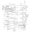
- FIG. 1 is a circuit diagram showing a fluid pressure control device including an internal pilot type flow control valve according to an embodiment of the present invention.
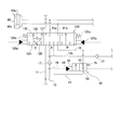
- FIG. 2 is an enlarged view of a part of the fluid pressure control apparatus including the flow control valve according to the embodiment of the present invention.
- FIG. 3 is a structural cross-sectional view of an internal pilot type flow control valve according to an embodiment of the present invention.
- FIG. 4 is a circuit diagram showing a fluid pressure control device including an external pilot type flow control valve according to an embodiment of the present invention.
- FIG. 5 is a structural cross-sectional view of an external pilot type flow control valve according to an embodiment of the present invention.
- the fluid pressure control device 100 is used in a working machine such as a power shovel.
- a working machine such as a power shovel
- the fluid pressure control device 100 can also be applied to other working machines such as a wheel loader.
- hydraulic oil is used as the working fluid, but other fluids such as hydraulic water may be used as the working fluid.
- the fluid pressure control apparatus 100 includes a first circuit system 10 connected to the first pump P1 and supplied with hydraulic oil from the first pump P1, and a second pump P2 connected to the second pump P2. And a second circuit system 20 to which hydraulic oil is supplied.
- the first circuit system 10 includes a first neutral passage 11 that guides hydraulic oil supplied from the first pump P1 to the tank T, a plurality of control valves 121 to 125 connected in series to the first neutral passage 11, And a first parallel passage 13 branched from the first neutral passage 11 upstream of the valves 121 to 125.
- the control valves 121 to 125 are connected in series by the first neutral passage 11 and are connected in parallel by the first parallel passage 13.
- the hydraulic oil discharged from the first pump P1 is, in order from the upstream side, the first traveling control valve 121, the spare control valve 122, the turning control valve 123, the first boom control valve 124, and the first arm. Guided to the control valve 125.
- the first travel control valve 121 controls supply and discharge of hydraulic oil to and from a travel motor provided on the left side of the vehicle body of a power shovel (not shown).
- the spare control valve 122 controls supply / discharge of hydraulic oil to / from an actuator that drives an attachment such as a breaker or a crusher attached instead of the bucket.
- the turning control valve 123 controls the supply and discharge of the hydraulic oil to and from the turning motor that turns the turning body disposed at the upper part of the vehicle body.
- the first boom control valve 124 controls supply / discharge of hydraulic oil to / from an actuator that drives the boom.
- the first arm control valve 125 controls supply / discharge of hydraulic oil to / from an actuator that drives the arm.
- the first pump The hydraulic oil supplied from P1 can be supplied to the control valves 122 to 125 through the first parallel passage 13.
- the fluid pressure control apparatus 100 forms a main body by laminating a plurality of valve blocks and tightening them by sandwiching them with bolts or the like.
- the fluid pressure control device 100 may be formed by a single valve block.
- the first circuit system 10 further includes a neutral cut valve 40 that is provided downstream of the control valves 121 to 125 in the first neutral passage 11 and communicates or cuts off the connection between the first neutral passage 11 and the tank T.
- the neutral cut valve 40 communicates the connection between the first neutral passage 11 and the tank T when in the G position (normal position) in FIG. 1, and when in the H position (blocking position), The connection with the tank T is cut off.
- FIG. 3 is a cross-sectional view showing a cross section when the neutral cut valve 40 is in the G position (normal position).
- the neutral cut valve 40 cuts off or communicates the connection between the valve block 60 having the bottomed cylindrical accommodation hole 61 and the first neutral passage 11 and the tank T accommodated in the accommodation hole 61.
- a spool 41 as a valve body, a drain chamber 48 defined between one end of the spool 41 and the bottom of the accommodation hole 61 and communicating with the tank T, a valve block 60 and a cap member 43 provided on the other end side of the spool 41 And a return spring 44 that is provided in the pilot pressure chamber 49 and biases the spool 41 in the direction in which the first neutral passage 11 and the tank T communicate with each other (the left direction in FIG. 2). And comprising.
- the cap member 43 is provided with a pilot port 42 for supplying and discharging pilot pressure to and from the pilot pressure chamber 49.
- the spool 41 includes a first land portion 45 and a second land portion 46 that slide along the inner peripheral surface of the accommodation hole 61, and an annular groove formed between the first land portion 45 and the second land portion 46. 47.
- the valve block 60 includes a neutral passage portion 66 that passes through the valve block 60 in a direction perpendicular to the axis of the receiving hole 61 and communicates with the downstream side of the first arm control valve 125, and the spool 41 is surrounded by the receiving hole 61.
- An inlet port portion 62 formed to communicate with the neutral passage portion 66 and an outlet port portion 63 formed so as to surround the spool 41 in the accommodation hole 61 and communicated with the tank T are formed.
- a flow path from the neutral passage portion 66 in the valve block 60 to the outlet port portion 63 through the inlet port portion 62 constitutes a part of the first neutral passage 11.
- the flow path from the neutral passage portion 66 to the outlet port portion 63 through the inlet port portion 62 corresponds to the in-block supply passage.
- the neutral cut valve 40 In the state where the hydraulic oil in the pilot pressure chamber 49 is not supplied, the neutral cut valve 40 is located in the state shown in FIG. 3, that is, in the G position (normal position) in FIG. In this state, the inlet port portion 62 and the outlet port portion 63 communicate with each other through an annular groove 47 formed in the spool 41. Therefore, the hydraulic oil that has flowed into the inlet port portion 62 from the neutral passage portion 66 communicating with the downstream of the first arm control valve 125 in the first neutral passage 11 passes through the annular groove 47 and the outlet port portion 63 to the tank T. Refluxed. That is, the first neutral passage 11 and the tank T communicate with each other by switching the neutral cut valve 40 to the G position (normal position).
- the first arm control valve 125 is supplied with hydraulic fluid for driving the arm cylinder 90 by branching from the first neutral passage 11 and the first neutral passage 11.
- a passage 12 a first cylinder passage 91 a communicating with the high load side pressure chamber 90 a in the arm cylinder 90, a second cylinder passage 91 b communicating with the low load side pressure chamber 90 b in the arm cylinder 90, and the pressure chamber 90 a
- the first tank passage 14 for discharging the hydraulic oil to the tank T and the second tank passage 15 for discharging the hydraulic oil in the pressure chamber 90b to the tank T are connected.
- a first parallel downstream passage 13b joins the supply passage 12.
- a check valve 17 for preventing the backflow of hydraulic oil is provided on the upstream side of the joining portion of the supply passage 12 and the first parallel passage 13.
- the first tank passage 14 is provided with a flow rate control valve 50 that controls the flow rate of the hydraulic oil passing through the first tank passage 14 in accordance with the pilot pressure.
- the first arm control valve 125 includes a neutral position A, a high load side operation position B shown on the right side of FIGS. 1 and 2, a low load side operation position C shown on the left side of FIGS. The three positions are switched.
- the positions A, B, and C of the first arm control valve 125 are switched according to the pilot pressure supplied to the pilot chambers 125 a and 125 b provided at both ends of the first arm control valve 125.
- the pilot pressure does not act on any of the pilot chambers 125a and 125b, the first arm control valve 125 is moved to the neutral position A by the urging force of the springs 125c provided on both sides of the first arm control valve 125. Become.
- the first arm control valve 125 When the pilot pressure is supplied to the pilot chamber 125b, the first arm control valve 125 is switched to the high load side operating position B. When the pilot pressure is supplied to the pilot chamber 125a, the first arm control valve 125 is Switches to the low load side operating position C.
- the first neutral passage 11 is connected to the tank T, and the other passages are blocked.
- the hydraulic oil is not supplied to or discharged from the pressure chambers 90a and 90b of the arm cylinder 90, and the arm cylinder 90 is held at that position.
- the first neutral passage 11 is blocked, the supply passage 12 is connected to the first cylinder passage 91a, and the second cylinder passage 91b is connected to the second tank passage 15. Accordingly, the hydraulic oil discharged from the first pump P1 is supplied from the first neutral passage 11 and the first parallel downstream passage 13b to the pressure chamber 90a through the supply passage 12 and the first cylinder passage 91a. Further, the hydraulic oil in the pressure chamber 90 b is discharged to the tank T through the second cylinder passage 91 b and the second tank passage 15.
- the first neutral passage 11 is blocked, the supply passage 12 is connected to the second cylinder passage 91b, and the first cylinder passage 91a is connected to the first tank passage 14.
- the hydraulic oil discharged from the first pump P1 is supplied from the first neutral passage 11 and the first parallel passage 13 to the pressure chamber 90b through the supply passage 12 and the second cylinder passage 91b.
- the hydraulic oil in the pressure chamber 90 a is discharged to the tank T through the first cylinder passage 91 a and the first tank passage 14.
- the flow rate of the hydraulic oil discharged to the tank T through the first tank passage 14 is controlled by the flow rate control valve 50.
- the first internal passage 126 that connects the first cylinder passage 91a and the first tank passage 14 at the low load side position C, the supply passage 12, and the second cylinder passage 91b.
- a regeneration passage 128 that connects the first internal passage 126 and the second internal passage 127 is formed (see FIG. 2).
- the regeneration passage 128 is provided with a check valve 129 that allows only the flow from the first internal passage 126 to the second internal passage 127. Therefore, the hydraulic oil discharged from the pressure chamber 90a can be regenerated into the pressure chamber 90b through the regeneration passage 128.
- the first internal passage 126 is provided with a throttle 130 that regulates the flow rate of the hydraulic oil discharged from the pressure chamber 90a.
- FIG. 1 a specific structure of the flow control valve 50 will be described with reference to FIGS. 1, 2, and 3.
- FIG. 1 a specific structure of the flow control valve 50 will be described with reference to FIGS. 1, 2, and 3.
- a flow control valve 50 shown in FIGS. 1, 2, and 3 is an internal pilot type flow control valve that is controlled by using hydraulic oil supplied through a pilot passage 16 branched from the supply passage 12 as a pilot pressure.
- the flow control valve 50 includes a valve block 60 in which a bottomed cylindrical accommodation hole 51 is formed, a sleeve 70 inserted into the accommodation hole 51, and the accommodation hole 51 via the sleeve 70. And a spool 80 as a valve body to be inserted.
- the neutral cut valve 40 and the flow rate control valve 50 use the valve block 60 as a common one, but each may have an individual valve block.
- the valve block 60 has a tank port 52 provided on the downstream side of the spool 80 in the first tank passage 14 from the opening side of the accommodation hole 51 so as to intersect the accommodation hole 51, and a first tank passage that communicates with the tank T. 14, an actuator discharge port 53 provided on the upstream side of the spool 80 and communicating with the first arm control valve 125, and an internal pilot port 54 communicating with the supply passage 12 through the pilot passage 16 are formed.
- a space 65 is formed on the flow path connecting the neutral passage portion 66 and the inlet port portion 62.
- the space 65 is formed at a position on the axis of the receiving hole 51 and spaced from the bottom of the receiving hole 51 to the side opposite to the opening.
- the neutral passage portion 66 may be formed at a position where the space 65 is provided.
- the sleeve 70 is formed in a hollow cylindrical shape.
- the sleeve 70 has a plurality of first through holes 71 that communicate with the tank port 52, a plurality of second through holes 72 that communicate with the actuator discharge port 53, and a plurality of slits formed on the end surface that contacts the receiving hole 51. 73 is formed.
- the sleeve 70 is accommodated in the accommodation hole 51 and fixed so as to be pressed against the bottom surface of the accommodation hole 51 by a plug 77 screwed into the valve block 60.
- the spool 80 includes a first land portion 81 and a second land portion 82 that slide along the inner peripheral surface of the sleeve 70, and an annular groove 83 formed between the first land portion 81 and the second land portion 82. And a piston 84 provided so as to be in contact with the end surface of the second land portion 82 opposite to the annular groove 83.
- the piston 84 may be formed integrally with the spool 80.
- the inner pilot pressure chamber 55 is defined by the inner peripheral surface of the sleeve 70 and the end surface of the piston 84 at the bottom of the accommodation hole 51.
- the internal pilot pressure chamber 55 communicates with the internal pilot port 54 through a slit 73.
- a spring accommodation space 74 is formed in which a spool spring 75 that urges the spool 80 toward the bottom surface of the accommodation hole 51 is accommodated.
- the spring accommodating space 74 communicates with the tank port 52 through the through hole 76.
- the second circuit system 20 includes a second neutral passage 21 that guides hydraulic oil supplied from the second pump P2 to the tank T, a plurality of control valves 221 to 224 connected in series to the second neutral passage 21, And a second parallel passage 23 branched from the second neutral passage 21 upstream of the valves 221 to 224.
- the control valves 221 to 224 are connected in series by the second neutral passage 21 and are connected in parallel by the second parallel passage 23.
- the hydraulic oil discharged from the second pump P2 is guided to the second traveling control valve 221, the bucket control valve 222, the second boom control valve 223, and the second arm control valve 224 in order from the upstream side. .
- the second travel control valve 221 controls supply and discharge of hydraulic oil to and from a travel motor provided on the right side of the vehicle body of a power shovel (not shown).
- the bucket control valve 222 controls supply and discharge of hydraulic oil to and from an actuator that drives the bucket.
- the second boom control valve 223 controls the supply and discharge of hydraulic oil to and from the actuator that drives the boom.
- the second arm control valve 224 controls supply and discharge of hydraulic oil to and from an actuator that drives the arm. Note that the control valves 221 to 224 correspond to second control valves.
- the second pump The hydraulic oil supplied from P2 can be supplied to the control valves 222 to 224 through the second parallel passage 23.
- the second circuit system 20 further includes a neutral cut valve 24 that is provided downstream of the second arm control valve 224 in the second neutral passage 21 and communicates or cuts off the connection between the second neutral passage 21 and the tank T.
- the neutral cut valve 24 has the same configuration as the neutral cut valve 40.
- the second circuit system 20 communicates in the second neutral passage 21 downstream of the second arm control valve 224 and upstream of the neutral cut valve 24, and supplies hydraulic oil discharged from the second pump P2 to the outside.
- a possible branch passage 29 is further provided.
- the second circuit system 20 further includes a straight travel control valve 25 connected downstream of the branch point of the second neutral passage 21 with the second parallel passage 23 and upstream of the second travel control valve 221.
- the first parallel passage 13 is connected to the straight travel control valve 25.
- the first parallel passage 13 is connected to the first parallel upstream passage 13a that connects the first pump P1 and the straight travel control valve 25, and the first parallel passage that connects the straight travel control valve 25 and the control valves 122 to 125.
- a downstream passage 13b is a downstream passage 13b.
- the straight travel control valve 25 is switched to a normal position D shown in the center of FIG. 1, a straight travel position E shown on the left side of FIG. 1, and a merging position F shown on the right side of FIG.
- the positions D, E, and F of the straight travel control valve 25 are switched according to the pilot pressure supplied to the pilot chambers 25a and 25b provided at both ends of the straight travel control valve 25.
- the straight travel control valve 25 assumes the normal position D by the biasing force of the springs 25c provided on both sides of the straight travel control valve 25.
- the travel rectilinear control valve 25 When the pilot pressure is supplied to the pilot chamber 25a, the travel rectilinear control valve 25 is switched to the travel rectilinear position E, and when the pilot pressure is supplied to the pilot chamber 25b, the travel rectilinear control valve 25 is set to the joining position F. Switch.
- the first parallel upstream passage 13a of the first parallel passage 13 is connected to the first parallel downstream passage 13b of the first parallel passage 13, and the second neutral passage 21 is connected to the second pump P2. Is done.
- the hydraulic oil discharged from the first pump P1 is supplied to the control valves 121 to 125 through the first neutral passage 11 and the first parallel passage 13.
- the hydraulic fluid discharged from the second pump P2 is supplied to the control valves 221 to 224 through the second neutral passage 21 and the second parallel passage 23. That is, when only the traveling motor is operated, the hydraulic oil discharged from the first pump P1 is supplied to the first traveling control valve 121, and the second pump P2 is supplied to the second traveling control valve 221.
- the hydraulic oil discharged from is supplied.
- the first parallel upstream passage 13a of the first parallel passage 13 is connected to the second neutral passage 21 downstream of the travel straight travel control valve 25, and the first parallel downstream passage 13b is the first parallel passage 13b.
- Two pumps P2 are connected. That is, when the travel motor and the actuator other than the travel motor are operated simultaneously, the hydraulic oil discharged from the first pump P1 is supplied to the first travel control valve 121 and the second travel control valve 221.
- the other control valves 122 to 125 and the other control valves 222 to 224 are supplied with hydraulic oil discharged from the second pump P2. Therefore, at the straight travel position E, even if the travel motor and the actuator other than the travel motor are operated simultaneously, the circuit for the travel motor and the circuit of the actuator other than the travel motor are independent. The traveling straightness of the vehicle is ensured.
- the second neutral passage 21 upstream from the straight travel control valve 25 is connected to the second neutral passage 21 downstream, and the first parallel upstream passage 13a It is connected to the second neutral passage 21 through a merge passage 26 formed inside the straight travel control valve 25.
- the hydraulic oil of the first pump P1 and the hydraulic oil of the second pump P2 merge and are supplied to the second control valve, and more hydraulic oil can be supplied to the actuator connected to the second control valve. it can.
- the junction passage 26 formed inside the straight travel control valve 25 includes a check valve 27 that allows only the flow from the first parallel upstream passage 13a to the second neutral passage 21, and the operation in the junction passage 26.
- a throttle 28 for restricting the flow of oil is provided in this order from the upstream side. Accordingly, the hydraulic oil of the second pump P2 can be prevented from flowing to the first parallel upstream passage 13a side, and the first control valve and the second control are controlled by limiting the hydraulic oil of the first parallel upstream passage 13a.
- the combined flow rate from the first pump P1 to the second pump P2 can be adjusted and combined with the second neutral passage 21 during the combined operation with the valve.
- a pilot pressure chamber of a bucket control valve 222 that controls the supply and discharge of hydraulic oil to and from the cylinder 22 that drives the bucket, a pilot pressure chamber 49 of the neutral cut valve 40, a pilot chamber 25b of the straight travel control valve 25, Supply hydraulic oil to As a result, when the bucket control valve 222 is operated, the operation discharged from the first pump P1 in addition to the hydraulic oil discharged from the second pump P2 to the second neutral passage 21 and the second parallel passage 23. Oil is supplied through the junction passage 26 of the straight travel control valve 25. Thereby, the cylinder 22 is driven in a state in which the hydraulic oil discharged from the first pump P1 joins the hydraulic oil discharged from the second pump P2. Therefore, the cylinder 22 can be driven at high speed.
- FIG. 3 is a diagram showing a state where the pilot pressure acting on the internal pilot pressure chamber 55 is low.
- the flow rate control valve 50 adjusts the flow rate of the hydraulic oil returned from the high load side pressure chamber 90a to the tank T through the first tank passage 14. To do. Specifically, when the pilot pressure is supplied to the pilot chamber 125 a of the first arm control valve 125, the first arm control valve 125 is switched to the low load side position C. As a result, the hydraulic oil in the pressure chamber 90a on the high load side of the arm cylinder 90 flows into the actuator discharge port 53 of the flow control valve 50 through the first cylinder passage 91a, the first internal passage 126, and the first tank passage 14. . The hydraulic fluid that has flowed into the actuator discharge port 53 flows into the annular groove 83 from the second through hole 72, and flows out to the tank port 52 through the first through hole 71.
- the spool 80 When the pilot pressure acting on the internal pilot pressure chamber 55 from the supply passage 12 through the pilot passage 16 is low, the spool 80 is urged toward the bottom surface side of the accommodation hole 51 by the spool spring 75. As a result, as shown in FIG. 3, the first land portion 81 of the spool 80 overlaps the first through hole 71 so that the flow passage area of the first through hole 71 is narrowed. In this state, the flow rate of the hydraulic oil that can pass through the first tank passage 14 is small. Therefore, most of the hydraulic oil discharged from the pressure chamber 90a is regenerated into the pressure chamber 90b through the regeneration passage 128.
- the flow rate of the hydraulic oil that can pass through the first tank passage 14 further increases. Therefore, the hydraulic oil is not regenerated from the pressure chamber 90 a to the pressure chamber 90 b through the regeneration passage 128, and the entire amount of hydraulic oil in the pressure chamber 90 a is discharged to the tank T.
- the flow rate control valve 50 adjusts the flow rate of the hydraulic oil passing through the first tank passage 14 in accordance with the pilot pressure acting on the internal pilot pressure chamber 55, whereby the pressure is controlled from the pressure chamber 90 a through the regeneration passage 128.
- the flow rate regenerated in the chamber 90b is adjusted.
- the flow rate control valve 50 can regenerate the hydraulic oil in the pressure chamber 90a to the pressure chamber 90b by restricting the first tank passage 14 as described above.
- the flow control valve 50 is By opening the first tank passage 14, the hydraulic oil in the pressure chamber 90a is discharged to the tank T without being regenerated into the pressure chamber 90b.
- the flow control valve 150 includes a valve block 160 having a bottomed cylindrical accommodation hole 151, a spool 180 as a valve body inserted into the accommodation hole 151, and one end of the spool 180 and the bottom of the accommodation hole 151.
- a drain port 156 that communicates with the tank T, an external pilot pressure chamber 155 that is provided on the other end side of the spool 180 and is defined by the valve block 160 and the cap member 173, and an external pilot pressure chamber 155.
- a spool spring 175 that urges the spool 180 in the direction of the cap member 173 (left direction in FIG. 5).
- the cap member 173 is provided with a pilot port 174 for supplying and discharging pilot pressure to and from the external pilot pressure chamber 155.
- valve block 160 of the flow control valve 150 shown in FIG. 5 and the valve block 60 of the flow control valve 50 shown in FIG. 3 are obtained by processing a valve block manufactured by a common mold.
- the accommodation hole 151 of the valve block 160 is deeper than the accommodation hole 51 in the valve block 60 and is processed so as to intersect the drain port 156.
- the valve block 160 is provided with the drain port 156 at a position between the internal pilot port 54 and the space 65. For this reason, in the valve block manufactured by the mold, a space in which the drain port 156 can be provided between the internal pilot port 54 and the space 65 is secured in advance. Specifically, the distance L1 between the space 65 on the axis of the receiving holes 51 and 151 and the internal pilot port 54 is greater than the distance L2 between the internal pilot port 54 and the actuator discharge port 53 on the axial lines of the receiving holes 51 and 151. Each port is arranged to be larger.
- the spool 180 is formed between the first land portion 181 and the second land portion 182 that slide along the inner peripheral surface of the receiving hole 151 of the valve block 160, and between the first land portion 181 and the second land portion 182. And a plurality of notches 184 provided at the end of the second land portion 182 on the annular groove 183 side.
- the flow control valve 150 may be provided with a sleeve between the valve block 160 and the spool 180.
- FIG. 5 is a diagram showing a state where the pilot pressure acting on the external pilot pressure chamber 155 is low.
- the flow rate control valve 150 adjusts the flow rate of the hydraulic oil returned from the high load side pressure chamber 90a to the tank T through the first tank passage 14. To do. Specifically, when the pilot pressure is supplied to the pilot chamber 125 a of the first arm control valve 125, the first arm control valve 125 is switched to the low load side position C. As a result, the hydraulic oil in the pressure chamber 90 a on the high load side of the arm cylinder 90 flows into the actuator discharge port 53 through the first cylinder passage 91 a, the first internal passage 126, and the first tank passage 14. The hydraulic fluid that has flowed into the actuator discharge port 53 flows out to the tank port 52 through the notch 184. At this time, the hydraulic oil acts on the internal pilot port 54 from the supply passage 12 through the pilot passage 16, but the internal pilot port 54 is always closed by the second land portion 182.
- the spool 180 When the pilot pressure is low, the spool 180 is urged toward the bottom surface of the receiving hole 151 by the spool spring 175. As a result, as shown in FIG. 5, the notch 184 of the second land portion 182 is in a state where the flow path area is narrowed. In this state, the flow rate of hydraulic oil that can pass through the notch 184 is small. Therefore, most of the hydraulic oil discharged from the pressure chamber 90a is regenerated into the pressure chamber 90b through the regeneration passage 128.
- the flow rate control valve 150 adjusts the flow rate of the hydraulic oil passing through the first tank passage 14 in accordance with the pilot pressure acting on the external pilot pressure chamber 155, thereby allowing the pressure from the pressure chamber 90 a to pass through the regeneration passage 128.
- the flow rate regenerated in the chamber 90b can be adjusted.
- the distance L1 between the space 65 on the axis of the accommodation hole 51 and the internal pilot port 54 is the distance L2 between the internal pilot port 54 and the actuator discharge port 53 on the axis of the accommodation hole 51. It is formed to be larger. Thereby, the space which adds the drain port 156 for using a flow control valve as an external pilot form is securable. Therefore, even if the internal pilot type valve block and the external pilot type valve block are made common, the internal pilot type valve block 60 can be used for the external pilot type flow control valve 150 only by a simple modification. Can do. That is, according to the flow control valves 50 and 150, the valve blocks used for the internal pilot type and the external pilot type flow control valves can be shared.
- the internal pilot port 54 is preferably provided at an approximately middle position between the tank port 52 and the space 65 on the axis of the accommodation hole 51.
- An actuator discharge port 53 is provided between the internal pilot port 54 and the tank port 52. That is, a space for providing the actuator discharge port 53 is secured between the internal pilot port 54 and the tank port 52. Since the distance L1 between the internal pilot port 54 and the space 65 is substantially equal to the distance L3 between the internal pilot port 54 and the tank port 52, a drain port 156 is formed between the internal pilot port 54 and the space 65. Space will be reserved in advance.
- the fluid pressure control device 100 is connected to the first pump P1 and controls supply / discharge of the working fluid to / from one and the other pressure chambers 90a, 90b of the actuator (arm cylinder 90), and discharge from the one pressure chamber 90a.
- the first arm control valve 125 having a regeneration passage 128 for regenerating the working fluid to be returned to the other pressure chamber 90b, and the working fluid of the first pump P1 when the first arm control valve 125 is in the neutral position
- a neutral passage (first neutral passage 11) that returns the fuel to the tank T
- a supply passage 12 that branches from the neutral passage (first neutral passage 11) and supplies hydraulic oil to the first arm control valve 125
- the first tank passage 14 provided between the control valve 125 and the tank T for discharging the hydraulic oil from one pressure chamber 90a of the actuator (arm cylinder 90) to the tank T.
- a second tank passage 15 provided between the first arm control valve 125 and the tank T for discharging hydraulic oil from the other pressure chamber 90b of the actuator (arm cylinder 90) to the tank T, and a first tank passage 14 and the flow rate control valves 50 and 150 for controlling the flow rate of the working fluid passing through the first tank passage 14 in accordance with the pilot pressure, and the flow rate control valves 50 and 150 are bottomed cylindrical accommodation holes.
- the valve blocks 60 and 160 in which 51 and 151 are formed and the valve bodies (spools 80 and 180) to be inserted into the receiving holes 51 and 151 are provided.
- Tank ports 51 and 151 are provided on the downstream side of the valve bodies (spools 80 and 180) in the first tank passage 14 so as to communicate with the tank T from the opening side of the receiving holes 51 and 151.
- 52 an actuator discharge port 53 provided on the upstream side of the valve body (spools 80, 180) in the first tank passage 14 and communicating with the first arm control valve 125, and an internal pilot port 54 communicating with the supply passage 12.
- a block supply passage neutral passage portion 66, space 65, inlet port portion 62, outlet port portion 63 to which the hydraulic oil discharged from the first pump P1 is supplied to the valve blocks 60 and 160.
- in-block supply passage (neutral passage portion 66, space 65, inlet port portion 62, outlet port portion 63) is on the axis of the receiving holes 51 and 151, and the receiving hole 51 , 151 is formed at a position spaced apart from the bottom of the opening on the side opposite to the opening, and the in-block supply passage (neutral passage portion 66 on the axis of the receiving holes 51, 151 is formed.
- Space 65, inlet port portion 62, outlet port portion 63) and internal pilot port 54 have a distance L1 that is greater than a distance L2 between internal pilot port 54 and actuator discharge port 53 on the axis of receiving holes 51 and 151. It is characterized by that.
- the in-block supply passage (neutral passage portion 66, space 65, inlet port portion 62, outlet port portion 63) on the axis of the receiving holes 51 and 151.
- the distance L1 between the internal pilot port 54 and the internal pilot port 54 is formed to be larger than the distance L2 between the internal pilot port 54 and the actuator discharge port 53 on the axis of the receiving holes 51 and 151.
- the flow control valves 50 and 150 are characterized in that the internal pilot port 54 is provided at a substantially intermediate position between the tank port 52 and the in-block supply passage (space 65) on the axis of the receiving holes 51 and 151. To do.
- the flow control valve 50 has a pilot pressure of the working fluid supplied to the internal pilot port 54, and the internal pilot port is located between the bottom of the accommodation hole 51 and one end face of the valve body (spool 80).
- An internal pilot pressure chamber 55 communicating with the valve 54 is formed, and the flow rate of the working fluid passing through the first tank passage 14 is controlled by moving the valve body (spool 80) according to the pilot pressure. .
- the flow control valve 50 can be used as an internal pilot type controlled by the working fluid supplied to the internal pilot port 54.
- one end face of the valve body (spool 180) is provided in the valve block 160 between the in-block supply passage (space 65) and the internal pilot port 54 on the axis of the accommodation hole 151.
- a drain port 156 that faces is further formed, and an external pilot pressure chamber 155 that faces the other end face of the valve body (spool 180) is formed between the valve block 160 and the cap member 173 provided outside the valve block 160,
- the pilot pressure is the pressure of the working fluid supplied to the external pilot pressure chamber 155.
- the pilot pressure acts on the other end surface of the valve body (spool 180), and the valve body (spool 180) responds to the pilot pressure.
- the flow rate of the working fluid passing through the first tank passage 14 is controlled by moving the first tank passage 14.
- the flow control valve 150 can be used as an external pilot type controlled by the working fluid supplied to the external pilot pressure chamber 155.
- the flow control valve 150 is characterized in that the internal pilot port 54 is always closed by a valve body (spool 180).
- the internal pilot port 54 is always closed by the valve body (spool 180), so that a simple additional process is added to the internal pilot type valve block 60. It can be used for the flow control valve 150 of the external pilot type.
- the flow control valves 50 and 150 are characterized in that the supply passage in the block is a part of the neutral passage (first neutral passage 11).
- control valves 121 to 125 may be provided.
- the second circuit system 20 may not be particularly provided.
- the in-block supply passage may be a part of the first parallel passage 13.
Landscapes
- Engineering & Computer Science (AREA)
- General Engineering & Computer Science (AREA)
- Mechanical Engineering (AREA)
- Physics & Mathematics (AREA)
- Fluid Mechanics (AREA)
- Chemical & Material Sciences (AREA)
- Analytical Chemistry (AREA)
- Fluid-Pressure Circuits (AREA)
- Mining & Mineral Resources (AREA)
- Civil Engineering (AREA)
- Structural Engineering (AREA)
- Valve Housings (AREA)
Abstract
Description
Claims (6)
- ポンプから供給される作動流体によって駆動されるアクチュエータを制御する流体圧制御装置に用いられる流量制御弁であって、
前記流体圧制御装置は、
前記ポンプに接続され前記アクチュエータの一方及び他方の圧力室への作動流体の給排を制御するとともに、前記一方の圧力室からの排出される作動流体を前記他方の圧力室に再生するための再生通路を有する制御弁と、
前記制御弁が中立位置にある場合に前記ポンプの作動流体をタンクに還流させる中立通路と、
前記中立通路から分岐し前記制御弁に作動流体を供給する供給通路と、
前記制御弁と前記タンクの間に設けられ前記アクチュエータの一方の圧力室から前記タンクに作動流体を排出するための第1タンク通路と、
前記制御弁と前記タンクの間に設けられ前記アクチュエータの他方の圧力室から前記タンクに作動流体を排出するための第2タンク通路と、
前記第1タンク通路に設けられ前記第1タンク通路を通過する作動流体の流量をパイロット圧力に応じて制御する前記流量制御弁と、を備え、
前記流量制御弁は、
有底円筒状の収容穴が形成されたバルブブロックと、
前記収容穴に挿入される弁体と、を有し、
前記バルブブロックには、前記収容穴と交わるように前記収容穴の開口部側から、前記第1タンク通路における前記弁体の下流側に設けられ前記タンクと連通するタンクポートと、前記第1タンク通路における前記弁体の上流側に設けられ前記制御弁に連通するアクチュエータ排出ポートと、前記供給通路に連通する内部パイロットポートと、が形成され、
前記バルブブロックには、前記ポンプから吐出された作動流体が供給されるブロック内供給通路がさらに形成され、
前記ブロック内供給通路は、少なくともその一部が前記収容穴の軸線上であって前記収容穴の底部から前記開口部とは反対側に離間した位置に形成され、
前記収容穴の前記軸線上における前記ブロック内供給通路と前記内部パイロットポートとの距離は、前記収容穴の前記軸線上における前記内部パイロットポートと前記アクチュエータ排出ポートとの距離よりも大きい流量制御弁。 - 請求項1に記載の流量制御弁であって、
前記内部パイロットポートは、前記収容穴の前記軸線上における前記タンクポートと前記ブロック内供給通路とのほぼ中間の位置に設けられる流量制御弁。 - 請求項1または2に記載の流量制御弁であって、
前記パイロット圧力は、前記内部パイロットポートに供給される作動流体の圧力であり、
前記収容穴の底部と前記弁体の一方の端面との間に前記内部パイロットポートと連通する内部パイロット圧室が形成され、
前記弁体が前記パイロット圧力に応じて移動することによって、前記第1タンク通路を通過する作動流体の流量を制御する流量制御弁。 - 請求項1または2に記載の流量制御弁であって、
前記バルブブロックには、前記収容穴の前記軸線上における前記ブロック内供給通路と前記内部パイロットポートとの間の位置に、前記弁体の一方の端面が臨むドレンポートがさらに形成され、
前記バルブブロックと前記バルブブロックの外部に設けられるキャップ部材との間に前記弁体の他方の端面が臨む外部パイロット圧室が形成され、
前記パイロット圧力は、前記外部パイロット圧室に供給される作動流体の圧力であり、
前記弁体が前記パイロット圧力に応じて移動することによって、前記第1タンク通路を通過する作動流体の流量を制御する流量制御弁。 - 請求項4に記載の流量制御弁であって、
前記内部パイロットポートは、前記弁体によって常に閉塞されている流量制御弁。 - 請求項1または2に記載の流量制御弁であって、
前記ブロック内供給通路は、前記中立通路の一部である流量制御弁。
Priority Applications (3)
| Application Number | Priority Date | Filing Date | Title |
|---|---|---|---|
| CN201680023812.5A CN107532617B (zh) | 2015-04-24 | 2016-04-08 | 流量控制阀 |
| KR1020177030764A KR20170130575A (ko) | 2015-04-24 | 2016-04-08 | 유량 제어 밸브 |
| GB1717277.6A GB2554244B (en) | 2015-04-24 | 2016-04-08 | Flow control valve |
Applications Claiming Priority (2)
| Application Number | Priority Date | Filing Date | Title |
|---|---|---|---|
| JP2015-089391 | 2015-04-24 | ||
| JP2015089391A JP6423754B2 (ja) | 2015-04-24 | 2015-04-24 | 流量制御弁 |
Publications (1)
| Publication Number | Publication Date |
|---|---|
| WO2016171015A1 true WO2016171015A1 (ja) | 2016-10-27 |
Family
ID=57143027
Family Applications (1)
| Application Number | Title | Priority Date | Filing Date |
|---|---|---|---|
| PCT/JP2016/061590 Ceased WO2016171015A1 (ja) | 2015-04-24 | 2016-04-08 | 流量制御弁 |
Country Status (5)
| Country | Link |
|---|---|
| JP (1) | JP6423754B2 (ja) |
| KR (1) | KR20170130575A (ja) |
| CN (1) | CN107532617B (ja) |
| GB (1) | GB2554244B (ja) |
| WO (1) | WO2016171015A1 (ja) |
Cited By (1)
| Publication number | Priority date | Publication date | Assignee | Title |
|---|---|---|---|---|
| CN111927844A (zh) * | 2020-07-16 | 2020-11-13 | 浙江工业大学 | 一种高频响高精度液压控制单元及其控制方法 |
Families Citing this family (4)
| Publication number | Priority date | Publication date | Assignee | Title |
|---|---|---|---|---|
| JP7021964B2 (ja) * | 2018-01-31 | 2022-02-17 | Kyb株式会社 | 弁装置 |
| EP3680491B1 (en) * | 2018-03-09 | 2024-12-04 | KYB Corporation | Control valve |
| JP6600386B1 (ja) * | 2018-07-06 | 2019-10-30 | Kyb株式会社 | 弁装置 |
| JP7543220B2 (ja) * | 2021-07-05 | 2024-09-02 | 仁科工業株式会社 | 方向切換弁 |
Citations (1)
| Publication number | Priority date | Publication date | Assignee | Title |
|---|---|---|---|---|
| US5862831A (en) * | 1996-05-21 | 1999-01-26 | Volvo Construction Equipment Korea Co., Ltd. | Variable-regeneration directional control valve for construction vehicles |
Family Cites Families (4)
| Publication number | Priority date | Publication date | Assignee | Title |
|---|---|---|---|---|
| JPH04312630A (ja) * | 1991-04-11 | 1992-11-04 | Hitachi Constr Mach Co Ltd | 建設機械の油圧回路 |
| JP4776366B2 (ja) * | 2005-12-14 | 2011-09-21 | カヤバ工業株式会社 | アクチュエータ制御装置 |
| US9309901B2 (en) * | 2011-07-12 | 2016-04-12 | Volvo Construction Equipment Ab | Flow control valve for construction machinery |
| CN103857850A (zh) * | 2011-10-07 | 2014-06-11 | 沃尔沃建造设备有限公司 | 用于施工机械的优先控制系统 |
-
2015
- 2015-04-24 JP JP2015089391A patent/JP6423754B2/ja active Active
-
2016
- 2016-04-08 WO PCT/JP2016/061590 patent/WO2016171015A1/ja not_active Ceased
- 2016-04-08 KR KR1020177030764A patent/KR20170130575A/ko not_active Withdrawn
- 2016-04-08 GB GB1717277.6A patent/GB2554244B/en active Active
- 2016-04-08 CN CN201680023812.5A patent/CN107532617B/zh active Active
Patent Citations (1)
| Publication number | Priority date | Publication date | Assignee | Title |
|---|---|---|---|---|
| US5862831A (en) * | 1996-05-21 | 1999-01-26 | Volvo Construction Equipment Korea Co., Ltd. | Variable-regeneration directional control valve for construction vehicles |
Cited By (1)
| Publication number | Priority date | Publication date | Assignee | Title |
|---|---|---|---|---|
| CN111927844A (zh) * | 2020-07-16 | 2020-11-13 | 浙江工业大学 | 一种高频响高精度液压控制单元及其控制方法 |
Also Published As
| Publication number | Publication date |
|---|---|
| GB201717277D0 (en) | 2017-12-06 |
| GB2554244A (en) | 2018-03-28 |
| GB2554244B (en) | 2020-08-26 |
| CN107532617A (zh) | 2018-01-02 |
| JP2016205549A (ja) | 2016-12-08 |
| CN107532617B (zh) | 2019-07-26 |
| JP6423754B2 (ja) | 2018-11-14 |
| KR20170130575A (ko) | 2017-11-28 |
Similar Documents
| Publication | Publication Date | Title |
|---|---|---|
| JP6423754B2 (ja) | 流量制御弁 | |
| KR101643069B1 (ko) | 주행 제어 밸브 | |
| JP6717541B2 (ja) | 弁装置およびこれを備えた流体圧システム | |
| KR101652612B1 (ko) | 하이브리드 건설 기계 | |
| US10233614B2 (en) | Fluid pressure control device | |
| JP6286482B2 (ja) | 流体圧制御装置 | |
| CA2932777C (en) | Hydraulic circuitry for skid steer loader valve | |
| KR101790427B1 (ko) | 방향 전환 밸브 | |
| JP6012021B2 (ja) | パワーショベルの流体圧制御装置 | |
| US11339884B2 (en) | Valve device | |
| CN108026942A (zh) | 阀装置 | |
| JP4020878B2 (ja) | 油圧制御装置 | |
| US11460053B2 (en) | Open center control valve configured to combine fluid flow received from multiple sources | |
| JP2020148233A (ja) | 制御弁及び建設機械用油圧システム | |
| WO2024127892A1 (ja) | 流体圧制御装置 | |
| JP3727738B2 (ja) | 油圧制御回路 | |
| JP2005127413A (ja) | 油圧制御装置 | |
| WO2023105719A1 (ja) | 切換弁 |
Legal Events
| Date | Code | Title | Description |
|---|---|---|---|
| 121 | Ep: the epo has been informed by wipo that ep was designated in this application |
Ref document number: 16783036 Country of ref document: EP Kind code of ref document: A1 |
|
| ENP | Entry into the national phase |
Ref document number: 201717277 Country of ref document: GB Kind code of ref document: A Free format text: PCT FILING DATE = 20160408 |
|
| ENP | Entry into the national phase |
Ref document number: 20177030764 Country of ref document: KR Kind code of ref document: A |
|
| NENP | Non-entry into the national phase |
Ref country code: DE |
|
| 122 | Ep: pct application non-entry in european phase |
Ref document number: 16783036 Country of ref document: EP Kind code of ref document: A1 |