WO2016170916A1 - 信号処理装置及び信号処理方法 - Google Patents
信号処理装置及び信号処理方法 Download PDFInfo
- Publication number
- WO2016170916A1 WO2016170916A1 PCT/JP2016/059648 JP2016059648W WO2016170916A1 WO 2016170916 A1 WO2016170916 A1 WO 2016170916A1 JP 2016059648 W JP2016059648 W JP 2016059648W WO 2016170916 A1 WO2016170916 A1 WO 2016170916A1
- Authority
- WO
- WIPO (PCT)
- Prior art keywords
- signal
- digital signal
- digital
- level
- converter
- Prior art date
- Legal status (The legal status is an assumption and is not a legal conclusion. Google has not performed a legal analysis and makes no representation as to the accuracy of the status listed.)
- Ceased
Links
Images




Classifications
-
- H—ELECTRICITY
- H04—ELECTRIC COMMUNICATION TECHNIQUE
- H04S—STEREOPHONIC SYSTEMS
- H04S1/00—Two-channel systems
- H04S1/007—Two-channel systems in which the audio signals are in digital form
-
- H—ELECTRICITY
- H03—ELECTRONIC CIRCUITRY
- H03G—CONTROL OF AMPLIFICATION
- H03G3/00—Gain control in amplifiers or frequency changers
- H03G3/20—Automatic control
- H03G3/30—Automatic control in amplifiers having semiconductor devices
- H03G3/3005—Automatic control in amplifiers having semiconductor devices in amplifiers suitable for low-frequencies, e.g. audio amplifiers
-
- H—ELECTRICITY
- H03—ELECTRONIC CIRCUITRY
- H03G—CONTROL OF AMPLIFICATION
- H03G3/00—Gain control in amplifiers or frequency changers
- H03G3/20—Automatic control
- H03G3/30—Automatic control in amplifiers having semiconductor devices
- H03G3/3089—Control of digital or coded signals
-
- H—ELECTRICITY
- H03—ELECTRONIC CIRCUITRY
- H03M—CODING; DECODING; CODE CONVERSION IN GENERAL
- H03M1/00—Analogue/digital conversion; Digital/analogue conversion
- H03M1/66—Digital/analogue converters
- H03M1/74—Simultaneous conversion
-
- H—ELECTRICITY
- H04—ELECTRIC COMMUNICATION TECHNIQUE
- H04R—LOUDSPEAKERS, MICROPHONES, GRAMOPHONE PICK-UPS OR LIKE ACOUSTIC ELECTROMECHANICAL TRANSDUCERS; ELECTRIC HEARING AIDS; PUBLIC ADDRESS SYSTEMS
- H04R3/00—Circuits for transducers
- H04R3/12—Circuits for transducers for distributing signals to two or more loudspeakers
- H04R3/14—Cross-over networks
-
- H—ELECTRICITY
- H04—ELECTRIC COMMUNICATION TECHNIQUE
- H04S—STEREOPHONIC SYSTEMS
- H04S2400/00—Details of stereophonic systems covered by H04S but not provided for in its groups
- H04S2400/13—Aspects of volume control, not necessarily automatic, in stereophonic sound systems
Definitions
- the present disclosure relates to a signal processing device and a signal processing method.
- a digital sound source such as a compact disc (CD) is used for an audio signal processing device which is one form of a signal processing device.
- CD compact disc
- the volume of a digital audio signal is not adjusted after DA conversion (digital / analog conversion) by a DA converter, but is adjusted on digital data before DA conversion.
- Patent Document 1 describes an example of means for adjusting the volume on digital data before DA conversion.
- the volume is reduced by reducing the digital data that is an audio signal.
- the bit resolution is lowered, so that the pulse waveform of the audio signal becomes rough, the sound quality is deteriorated, and the correlation between the input and output levels is shifted.
- An object of the embodiment is to provide a signal processing device and a signal processing method capable of suppressing the deterioration of sound quality and improving the correlation between input and output levels as compared with the prior art even when the volume is reduced.
- the first level conversion unit that converts the level of the first digital signal into the second digital signal, and the first level that converts the level of the third digital signal into the fourth digital signal.
- a second level converter a fifth digital signal obtained by subtracting the fourth digital signal from the second digital signal, a first digital signal added with the first digital signal, and the fourth digital signal.
- An arithmetic unit that generates the digital signal 6, a first DA converter that converts the fifth digital signal into a first analog signal, and a DA converter that converts the sixth digital signal into a second analog signal
- a signal processing apparatus comprising: a second DA converter configured to add; and an adder that adds the first analog signal and the second analog signal to generate a third analog signal. .
- the first digital signal is level-converted to a second digital signal
- the third digital signal is level-converted to a fourth digital signal
- the second digital signal is A fifth digital signal obtained by subtracting the fourth digital signal
- a sixth digital signal obtained by adding the first digital signal and the fourth digital signal; and generating the fifth digital signal.
- a signal is DA-converted into a first analog signal
- the sixth digital signal is DA-converted into a second analog signal
- the first analog signal and the second analog signal are added to form a third analog signal.
- a signal processing method is provided that generates an analog signal.
- the signal processing device and the signal processing method of the embodiment even when the volume is reduced, it is possible to suppress the deterioration of the sound quality as compared with the conventional case and to improve the correlation between the input and output levels.
- FIG. 1 is a conceptual diagram for explaining a signal processing apparatus according to an embodiment.
- FIG. 2 is a conceptual diagram for explaining a signal processing apparatus of a comparative example.
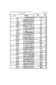
- FIG. 3A is a diagram illustrating a simulation result of an input / output level of the signal processing device of the comparative example.
- FIG. 3B is a diagram illustrating the simulation result of the input / output level of the signal processing device of the comparative example.
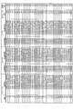
- FIG. 4A is a diagram illustrating a simulation result of an input / output level of the signal processing device according to the embodiment.
- FIG. 4B is a diagram illustrating an input / output level simulation result of the signal processing apparatus according to the embodiment.
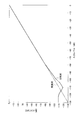
- FIG. 5 is a correlation diagram of input / output levels of the signal processing apparatuses of the example and the comparative example.
- an audio signal processing apparatus will be described as one form of the signal processing apparatus.
- the audio signal processing apparatus 1 includes a control unit 2, a playback unit 3, a DSP (digital signal processor) 4, DA converters 5, 6, 7 and 8, adders 9 and 10, and amplifiers 11 and 12. And speakers 13 and 14.
- Control unit 2 controls playback unit 3 and DSP 4.
- the playback unit 3 outputs a digital audio signal from a digital sound source such as a CD to the DSP 4.
- the digital audio signal is an L channel and R channel stereo signal.
- the symbol L in FIG. 1 is an L-channel digital audio signal (first digital signal).
- the symbol R is an R channel digital audio signal (third digital signal).
- the L channel audio signal is referred to as an audio signal L
- the R channel audio signal is referred to as an audio signal R.
- the DSP 4 includes volumes 41 and 42 and a calculation unit 43.
- the audio signal L is input to the volume 41 from the playback unit 3.
- the volume of the audio signal L is adjusted on the digital data by the volume 41. Specifically, the volume of the audio signal L is multiplied by a coefficient ⁇ for adjusting to a desired volume by the volume 41, and the level is converted into an audio signal (second digital signal) ⁇ L.
- the volume 41 functions as a level conversion unit (first level conversion unit) that converts the level of the first digital signal L to the second digital signal ⁇ L.
- the audio signal R is input from the playback unit 3 to the volume 42.
- the volume of the audio signal R is adjusted on the digital data by the volume 42. Specifically, the audio signal R is multiplied by a coefficient ⁇ for adjusting to a desired volume by the volume 42, and the level is converted into an audio signal (fourth digital signal) ⁇ R.
- the volume 42 functions as a level conversion unit (second level conversion unit) that converts the level of the third digital signal R into the fourth digital signal ⁇ R.
- the coefficient ⁇ is set to an arbitrary value from -1 to +1.
- the audio signal L and the audio signal R are input from the reproduction unit 3 to the calculation unit 43.
- the audio signal ⁇ L level-converted by the volume 41 is input to the calculation unit 43.
- the audio signal ⁇ R level-converted by the volume 42 is input to the calculation unit 43.
- the computing unit 43 generates a digital signal (fifth digital signal) ⁇ L- ⁇ R obtained by subtracting the audio signal ⁇ R from the audio signal ⁇ L, and outputs the digital signal to the DA converter (first DA converter) 5.
- the calculation unit 43 generates a digital signal (sixth digital signal) L + ⁇ R obtained by adding the audio signal L and the audio signal ⁇ R, and outputs the digital signal to the DA converter (second DA converter) 6.
- the calculation unit 43 generates a digital signal (seventh digital signal) R + ⁇ L obtained by adding the audio signal R and the audio signal ⁇ L, and outputs the digital signal to the DA converter (third DA converter) 7.
- the computing unit 43 generates a digital signal (eighth digital signal) ⁇ R- ⁇ L obtained by subtracting the audio signal ⁇ L from the audio signal ⁇ R, and outputs the digital signal to the DA converter (fourth DA converter) 8.
- the DA converter 5 DA-converts the digital signal ⁇ L- ⁇ R and outputs an analog signal (first analog signal) ⁇ L- ⁇ R to the adder (first adder) 9.
- the DA converter 6 DA-converts the digital signal L + ⁇ R and outputs an analog signal (second analog signal) L + ⁇ R to the adder 9.
- the DA converter 7 DA-converts the digital signal R + ⁇ L and outputs an analog signal (fourth analog signal) R + ⁇ L to the adder (second adder) 10.
- the DA converter 8 DA-converts the digital signal ⁇ R- ⁇ L and outputs an analog signal (fifth analog signal) ⁇ R- ⁇ L to the adder 10.
- the same reference numerals are used for digital signals before DA conversion by the DA converters 5 to 8 and analog signals after DA conversion.
- the adder 9 adds the analog signal ⁇ L ⁇ R and the analog signal L + ⁇ R to generate an analog signal (third analog signal) (1 + ⁇ ) L.
- the analog signal (1 + ⁇ ) L is output to the amplifier 11 as an L channel audio signal Lch.
- the adder 10 adds the analog signal R + ⁇ L and the analog signal ⁇ R ⁇ L to generate an analog signal (sixth analog signal) (1 + ⁇ ) R.
- the analog signal (1 + ⁇ ) R is output to the amplifier 12 as an R channel audio signal Rch.
- the audio signal Rch is expressed by Expression (2).
- the audio signal Lch is amplified by the amplifier 11 and output to the speaker 13.
- the audio signal Rch is amplified by the amplifier 12 and output to the speaker 14.
- the audio signal processing apparatus 20 of the comparative example includes a control unit 21, a reproduction unit 22, a DSP 23, DA converters 24 and 25, amplifiers 26 and 27, and speakers 28 and 29.
- the DSP 23 has volumes 31 and 32.
- the control unit 21, playback unit 22, DSP 23, amplifiers 26 and 27, speakers 28 and 29, and volumes 31 and 32 are the control unit 2, playback unit 3, DSP 4, amplifiers 11 and 12, and speakers 13 and 14 in FIG. , And volumes 41 and 42, respectively.
- the DA converter 24 corresponds to the DA converter 5 or the DA converter 6 of FIG.
- the DA converter 25 corresponds to the DA converter 7 or the DA converter 8 of FIG.
- the audio signals L, R, ⁇ L, and ⁇ R are processed on the digital data by the calculation unit 43, and the digital signals ⁇ L- ⁇ R, L + ⁇ R, R + ⁇ L, ⁇ R- ⁇ L are obtained. Generate.
- the digital signals ⁇ L- ⁇ R, L + ⁇ R, R + ⁇ L, ⁇ R- ⁇ L are DA-converted by the corresponding first to fourth DA converters 5, 6, 7, 8 respectively.
- the audio signal processing apparatus 20 of the comparative example performs DA conversion of the first and second audio signals ⁇ L and ⁇ R whose volume is adjusted on the digital data by the volumes 31 and 32 by the DA converters 24 and 25. This is different from the audio signal processing apparatus 1 of the embodiment.
- 3A and 3B show simulation results of the input level of the audio signal ⁇ L input to the DA converter 24 and the output level of the audio signal Lch output from the DA converter 24 in the audio signal processing device 20 of the comparative example.
- FIG. 3A and 3B show simulation results of the input level of the audio signal ⁇ L input to the DA converter 24 and the output level of the audio signal Lch output from the DA converter 24 in the audio signal processing device 20 of the comparative example.
- FIG. 3A shows a range where the input level is 0 dB to ⁇ 68 dB.
- FIG. 3B shows a range where the input level is -70 dB to -140 dB.
- the column of input level (dB) in FIGS. 3A and 3B indicates the input level of the audio signal ⁇ L input to the DA converter 24 in FIG.
- the input level (relative value) column shows the input level of the audio signal ⁇ L as a relative value when the state where the input level is 0 dB is 1.
- the column of output level (dB) indicates the output level of the audio signal Lch output from the DA converter 24.
- the error column shows the difference between the output level and the input level.
- an error occurs in the output level when the input level becomes -80 dB or less.
- the output level error increases as the input level decreases, that is, as the volume decreases.
- the error that occurs in the output level when the input level is below -80 dB is mainly due to the performance of the DA converter. That is, in the audio signal processing device 20 of the comparative example, the input / output level correlation varies depending on the performance of the DA converter.
- FIG. 10 is a diagram illustrating simulation results of the output level and the output level of the audio signal Lch output from the adder 9.
- FIG. 4A shows a range where the input level is 0 dB to ⁇ 68 dB.
- FIG. 4B shows a range where the input level is ⁇ 70 dB to ⁇ 140 dB.
- the input level (dB) column indicates the input level of the audio signal ⁇ L input to the calculation unit 43 in FIG.
- the input level (relative value) column shows the input level of the audio signal ⁇ L as a relative value when the state where the input level is 0 dB is 1.
- the column of ⁇ L- ⁇ R (before DA conversion) indicates the input level of the digital signal ⁇ L- ⁇ R output from the calculation unit 43 in FIG.
- the column of ⁇ L- ⁇ R (after DA conversion) indicates the output level of the analog signal ⁇ L- ⁇ R output from the DA converter 5 to the adder 9.
- the column of L + ⁇ R (before DA conversion) indicates the input level of the digital signal L + ⁇ R output from the calculation unit 43 in the DA converter 6.
- the column of L + ⁇ R (after DA conversion) indicates the output level of the analog signal L + ⁇ R output from the DA converter 6 to the adder 9.
- the digital signal L + ⁇ R is set to a level obtained by adding 0.011 dB to the digital signal L + ⁇ R.
- the column of output level indicates the output level of the audio signal Lch output from the adder 9.
- the error column shows the difference between the output level and the input level.
- the input level of the DA converter 24 is 0.0001 or less.
- the input level of the digital signal ⁇ L- ⁇ R to the DA converter 5 and The input levels of the digital signal L + ⁇ R to the DA converter 6 are both higher than 0.0001.
- the audio signal processing device 1 of the embodiment it is possible to suppress a decrease in bit resolution even if the volume is reduced, and the input of the DA converters 5 and 6 is not affected by the performance of the DA converters 5 and 6. Correlation between output levels is ensured.
- the analog signal ⁇ L- ⁇ R and the analog signal L + ⁇ R of the output level having a correlation with the input level are added to the DA converters 5 and 6 by the adder 9. Therefore, in the audio signal processing apparatus 1 of the embodiment, the input level and the output level of the audio signal have a correlation, and no error occurs.
- the conversion noise after DA conversion and external noise are 6 dB lower if they are not in phase, and can be canceled if they are in phase.
- FIG. 5 is a correlation diagram of audio signal input / output levels in the audio signal processing apparatus 1 of the embodiment and the audio signal processing apparatus 20 of the comparative example.
- the input level and the output level have a correlation indicating characteristics as indicated by a solid line.
- the characteristic is as shown by a solid line as in the audio signal processing apparatus 20 of the comparative example, and when the input level is ⁇ 80 dB or lower, the characteristic is shown by a one-dot chain line. Correlation shown.
- the output level has a correlation with the input level when the input level is ⁇ 80 dB or more, the correlation is shifted when the input level is ⁇ 80 dB or less.
- the output level has a correlation with the input level even if the input level is ⁇ 80 dB or less.
- the signal processing device 1 and the signal processing method of the embodiment since it is possible to suppress a decrease in bit resolution that occurs when the volume is reduced, it is possible to suppress deterioration in sound quality as compared with the conventional case, and to output the input level. Level correlation can be improved.
- the audio signal L is the first digital signal
- the audio signal ⁇ L is the second digital signal
- the audio signal R is the third digital signal
- the audio signal ⁇ R is the fourth digital signal. L and R may be reversed.
- the audio signal R may be the first digital signal
- the audio signal ⁇ R may be the second digital signal
- the audio signal L may be the third digital signal
- the audio signal ⁇ L may be the fourth digital signal.
- the digital signal ⁇ R- ⁇ L is the fifth digital signal.
- the digital signal R + ⁇ L becomes the sixth digital signal.
- the digital signal L + ⁇ R becomes the seventh digital signal.
- the digital signal ⁇ L- ⁇ R becomes the fifth digital signal.
- the DA converter 8 is the first DA converter.
- the DA converter 7 is a second DA converter.
- the DA converter 6 is a third DA converter.
- the DA converter 5 is a fourth DA converter.
- the adder 10 becomes a first adder.
- the adder 9 becomes a second adder.
- the signal processing apparatus and the signal processing method of the present invention can be used for level adjustment (volume adjustment) of a digital signal (digital audio signal).
Landscapes
- Engineering & Computer Science (AREA)
- Multimedia (AREA)
- Physics & Mathematics (AREA)
- Acoustics & Sound (AREA)
- Signal Processing (AREA)
- Theoretical Computer Science (AREA)
- Analogue/Digital Conversion (AREA)
- Amplifiers (AREA)
- Control Of Amplification And Gain Control (AREA)
Abstract
第1のレベル変換部(41)は第1のデジタル信号(L)を第2のデジタル信号(αL)にレベル変換する。第2のレベル変換部(42)は第3のデジタル信号(R)を第4のデジタル信号(αR)にレベル変換する。演算部(43)は第2のデジタル信号(αL)から第4のデジタル信号(αR)が減算された第5のデジタル信号(αL-αR)、及び、第1のデジタル信号(L)と第4のデジタル信号(αR)とが加算された第6のデジタル信号(L+αR)を生成する。第1のDAコンバータ(5)は第5のデジタル信号(αL-αR)を第1のアナログ信号(αL-αR)にDA変換する。第2のDAコンバータ(6)は第6のデジタル信号(L+αR)を第2のアナログ信号(L+αR)にDA変換する。加算器(9)は第1のアナログ信号(αL-αR)と第2のアナログ信号(L+αR)とを加算してアナログ信号((1+α)L)を生成する。
Description
本開示は信号処理装置及び信号処理方法に関する。
信号処理装置の一形態であるオーディオ信号処理装置には、一般的にコンパクトディスク(CD)等のデジタル音源が用いられている。最近では、デジタルオーディオ信号を、DAコンバータによりDA変換(デジタル・アナログ変換)した後に音量調整するのではなく、DA変換する前にデジタルデータ上で音量調整している。
特許文献1には、DA変換する前にデジタルデータ上で音量を調整する手段の一例が記載されている。
一般的に、DA変換する前にデジタルデータ上で音量を調整する場合、オーディオ信号であるデジタルデータを小さくすることで、音量を小さくしている。
しかしながら、特許文献1に記載されているような従来の信号処理装置では、音量を小さくするほど、下位ビットが失われていくため、ビット分解能が低下する。
従って、従来の信号処理装置では、音量を小さくするとビット分解能が低下するため、オーディオ信号のパルス波形が粗くなって音質を悪化させたり、入出力レベルの相関性にずれが生じたりする。
実施形態は、音量を小さくした場合においても、従来よりも音質の悪化を抑制し、入出力レベルの相関性を改善することができる信号処理装置及び信号処理方法を提供することを目的とする。
実施形態の第1の態様によれば、第1のデジタル信号を第2のデジタル信号にレベル変換する第1のレベル変換部と、第3のデジタル信号を第4のデジタル信号にレベル変換する第2のレベル変換部と、前記第2のデジタル信号から前記第4のデジタル信号が減算された第5のデジタル信号と、前記第1のデジタル信号と前記第4のデジタル信号とが加算された第6のデジタル信号とを生成する演算部と、前記第5のデジタル信号を第1のアナログ信号にDA変換する第1のDAコンバータと、前記第6のデジタル信号を第2のアナログ信号にDA変換する第2のDAコンバータと、前記第1のアナログ信号と前記第2のアナログ信号とを加算して第3のアナログ信号を生成する加算器とを備えることを特徴とする信号処理装置が提供される。
実施形態の第2の態様によれば、第1のデジタル信号を第2のデジタル信号にレベル変換し、第3のデジタル信号を第4のデジタル信号にレベル変換し、前記第2のデジタル信号から前記第4のデジタル信号が減算された第5のデジタル信号と、前記第1のデジタル信号と前記第4のデジタル信号とが加算された第6のデジタル信号とを生成し、前記第5のデジタル信号を第1のアナログ信号にDA変換し、前記第6のデジタル信号を第2のアナログ信号にDA変換し、前記第1のアナログ信号と前記第2のアナログ信号とを加算して第3のアナログ信号を生成することを特徴とする信号処理方法が提供される。
実施形態の信号処理装置及び信号処理方法によれば、音量を小さくした場合においても、従来よりも音質の悪化を抑制し、入出力レベルの相関性を改善することができる。
本実施形態では、信号処理装置の一形態として、オーディオ信号処理装置について説明する。
図1に示すように、オーディオ信号処理装置1は、制御部2、再生部3、DSP(digital signal processor)4、DAコンバータ5,6,7,8、加算器9,10、アンプ11,12、及び、スピーカ13,14を備えている。
制御部2は、再生部3及びDSP4を制御する。
再生部3は、CD等のデジタル音源からデジタルオーディオ信号をDSP4へ出力する。デジタルオーディオ信号は、LチャンネルとRチャンネルのステレオ信号である。
なお、図1中の符号LはLチャンネルのデジタルオーディオ信号(第1のデジタル信号)である。符号RはRチャンネルのデジタルオーディオ信号(第3のデジタル信号)である。以降、Lチャンネルのオーディオ信号をオーディオ信号Lと称し、Rチャンネルのオーディオ信号をオーディオ信号Rと称す。
DSP4は、ボリューム41,42と演算部43とを有する。
ボリューム41には再生部3からオーディオ信号Lが入力される。オーディオ信号Lは、ボリューム41によってデジタルデータ上で音量調整される。具体的には、オーディオ信号Lは、ボリューム41により、所望の音量に調整するための係数αが乗算され、オーディオ信号(第2のデジタル信号)αLにレベル変換される。
即ち、ボリューム41は、第1のデジタル信号Lを第2のデジタル信号αLにレベル変換するレベル変換部(第1のレベル変換部)として機能する。
ボリューム42には再生部3からオーディオ信号Rが入力される。オーディオ信号Rは、ボリューム42によってデジタルデータ上で音量調整される。具体的には、オーディオ信号Rは、ボリューム42により、所望の音量に調整するための係数αが乗算され、オーディオ信号(第4のデジタル信号)αRにレベル変換される。
即ち、ボリューム42は、第3のデジタル信号Rを第4のデジタル信号αRにレベル変換するレベル変換部(第2のレベル変換部)として機能する。
なお、係数αは-1から+1までの任意の値に設定される。
演算部43には、再生部3からオーディオ信号L及びオーディオ信号Rが入力される。演算部43には、ボリューム41でレベル変換されたオーディオ信号αLが入力される。演算部43には、ボリューム42でレベル変換されたオーディオ信号αRが入力される。
演算部43は、オーディオ信号αLからオーディオ信号αRが減算されたデジタル信号(第5のデジタル信号)αL-αRを生成し、DAコンバータ(第1のDAコンバータ)5へ出力する。
演算部43は、オーディオ信号Lとオーディオ信号αRとが加算されたデジタル信号(第6のデジタル信号)L+αRを生成し、DAコンバータ(第2のDAコンバータ)6へ出力する。
演算部43は、オーディオ信号Rとオーディオ信号αLとが加算されたデジタル信号(第7のデジタル信号)R+αLを生成し、DAコンバータ(第3のDAコンバータ)7へ出力する。
演算部43は、オーディオ信号αRからオーディオ信号αLが減算されたデジタル信号(第8のデジタル信号)αR-αLを生成し、DAコンバータ(第4のDAコンバータ)8へ出力する。
DAコンバータ5は、デジタル信号αL-αRをDA変換し、アナログ信号(第1のアナログ信号)αL-αRを加算器(第1の加算器)9へ出力する。
DAコンバータ6は、デジタル信号L+αRをDA変換し、アナログ信号(第2のアナログ信号)L+αRを加算器9へ出力する。
DAコンバータ7は、デジタル信号R+αLをDA変換し、アナログ信号(第4のアナログ信号)R+αLを加算器(第2の加算器)10へ出力する。
DAコンバータ8は、デジタル信号αR-αLをDA変換し、アナログ信号(第5のアナログ信号)αR-αLを加算器10へ出力する。便宜上、DAコンバータ5~8によるDA変換前のデジタル信号とDA変換後のアナログ信号とで同じ符号を用いている。
加算器9は、アナログ信号αL-αRとアナログ信号L+αRとを加算してアナログ信号(第3のアナログ信号)(1+α)Lを生成する。アナログ信号(1+α)Lは、Lチャンネルのオーディオ信号Lchとしてアンプ11へ出力される。
オーディオ信号Lchは、式(1)で表される。
Lch=(αL-αR)+(L+αR)=(1+α)L …(1)
Lch=(αL-αR)+(L+αR)=(1+α)L …(1)
加算器10は、アナログ信号R+αLとアナログ信号αR-αLとを加算してアナログ信号(第6のアナログ信号)(1+α)Rを生成する。アナログ信号(1+α)Rは、Rチャンネルのオーディオ信号Rchとしてアンプ12へ出力される。
オーディオ信号Rchは、式(2)で表される。
Rch=(R+αL)+(αR-αL)=(1+α)R …(2)
Rch=(R+αL)+(αR-αL)=(1+α)R …(2)
オーディオ信号Lchは、アンプ11で増幅されてスピーカ13へ出力される。オーディオ信号Rchは、アンプ12で増幅されてスピーカ14へ出力される。
ここで、図2を用いて、比較例のオーディオ信号処理装置について説明する。
比較例のオーディオ信号処理装置20は、制御部21、再生部22、DSP23、DAコンバータ24,25、アンプ26,27、及び、スピーカ28,29を備えている。DSP23は、ボリューム31,32を有する。
制御部21、再生部22、DSP23、アンプ26,27、スピーカ28,29、及び、ボリューム31,32は、図1の制御部2、再生部3、DSP4、アンプ11,12、スピーカ13,14、及び、ボリューム41,42にそれぞれ対応する。DAコンバータ24は図1のDAコンバータ5またはDAコンバータ6に対応する。DAコンバータ25は図1のDAコンバータ7またはDAコンバータ8に対応する。
図1に示す実施形態のオーディオ信号処理装置1は、オーディオ信号L,R,αL,αRを演算部43によってデジタルデータ上で演算処理し、デジタル信号αL-αR、L+αR、R+αL、αR-αLを生成する。デジタル信号αL-αR、L+αR、R+αL、αR-αLは、それぞれ対応する第1~第4のDAコンバータ5,6,7,8でDA変換される。
それに対して、比較例のオーディオ信号処理装置20は、ボリューム31,32によってデジタルデータ上で音量調整された第1及び第2のオーディオ信号αL,αRをDAコンバータ24,25でDA変換する点で実施形態のオーディオ信号処理装置1と相違する。
図3A及び図3Bは、比較例のオーディオ信号処理装置20において、DAコンバータ24に入力されるオーディオ信号αLの入力レベルと、DAコンバータ24から出力されるオーディオ信号Lchの出力レベルのシミュレーション結果を示す図である。
なお、図3Aは入力レベルが0dB~-68dBの範囲を示している。図3Bは入力レベルが-70dB~-140dBの範囲を示している。
図3A及び図3B中の入力レベル(dB)の欄は、図2中のDAコンバータ24に入力されるオーディオ信号αLの入力レベルを示している。入力レベル(相対値)の欄はオーディオ信号αLの入力レベルを、入力レベルが0dBである状態を1としたときの相対値で示している。
出力レベル(dB)の欄は、DAコンバータ24から出力されるオーディオ信号Lchの出力レベルを示している。誤差の欄は、入力レベルに対する出力レベルの差分を示している。
比較例のオーディオ信号処理装置20では、入力レベルが-80dB以下になると、出力レベルに誤差が生じる。出力レベルの誤差は、入力レベルが小さくなるほど、即ち、音量を小さくするほど、大きくなる。
入力レベルが-80dB以下になると出力レベルに生じる誤差は、主として、DAコンバータの性能に起因する。即ち、比較例のオーディオ信号処理装置20では、DAコンバータの性能によって入出力レベルの相関性にずれが生じる。
図4A及び図4Bは、実施形態のオーディオ信号処理装置1において、演算部43に入力されるオーディオ信号αLの入力レベルと、DAコンバータ5,6に入力されるデジタル信号αL-αR,L+αRの入出力レベルと、加算器9から出力されるオーディオ信号Lchの出力レベルのシミュレーション結果を示す図である。
なお、図4Aは入力レベルが0dB~-68dBの範囲を示している。図4Bは入力レベルが-70dB~-140dBの範囲を示している。
図4A及び図4B中の入力レベル(dB)の欄は図1中の演算部43に入力されるオーディオ信号αLの入力レベルを示している。入力レベル(相対値)の欄はオーディオ信号αLの入力レベルを、入力レベルが0dBである状態を1としたときの相対値で示している。
αL-αR(DA変換前)の欄は、図1中の演算部43から出力されるデジタル信号αL-αRのDAコンバータ5での入力レベルを示している。αL-αR(DA変換後)の欄は、DAコンバータ5から加算器9へ出力されるアナログ信号αL-αRの出力レベルを示している。
L+αR(DA変換前)の欄は、演算部43から出力されるデジタル信号L+αRのDAコンバータ6での入力レベルを示している。L+αR(DA変換後)の欄は、DAコンバータ6から加算器9へ出力されるアナログ信号L+αRの出力レベルを示している。なお、デジタル信号L+αRはデジタル信号L+αRよりも0.011dB分が加算されたレベルになるように設定されている。
出力レベルの欄は、加算器9から出力されるオーディオ信号Lchの出力レベルを示している。誤差の欄は、入力レベルに対する出力レベルの差分を示している。
図3A及び図3Bに示すように、比較例のオーディオ信号処理装置20では、入力レベルが-80dB以下になると、出力レベルに誤差が生じる。この場合のDAコンバータ24の入力レベルは0.0001以下である。
それに対して、図4A及び図4Bに示すように、実施形態のオーディオ信号処理装置1では、入力レベルが-80dB以下であっても、デジタル信号αL-αRのDAコンバータ5への入力レベル、及び、デジタル信号L+αRのDAコンバータ6への入力レベルは、いずれも0.0001よりも大きいレベルである。
従って、実施形態のオーディオ信号処理装置1によれば、音量を小さくしてもビット分解能の低下を抑制することができ、DAコンバータ5,6の性能に影響されず、DAコンバータ5,6の入出力レベルの相関性が確保される。
DAコンバータ5,6に対して入力レベルとそれぞれ相関性を有する出力レベルのアナログ信号αL-αRとアナログ信号L+αRとが加算器9で加算される。従って、実施形態のオーディオ信号処理装置1では、オーディオ信号の入力レベルと出力レベルとは相関性を有し、誤差が生じない。
また、DA変換された後にアナログ信号αL-αRとアナログ信号L+αRとが加算されるので、DA変換後の変換ノイズや外部ノイズが同相でない場合は6dB下がり、同相の場合は打ち消すことができる。
なお、Rチャンネルのオーディオ信号のDA変換についても、上記のLチャンネルのオーディオ信号のDA変換と同様の効果が得られる。
図5は、実施例のオーディオ信号処理装置1及び比較例のオーディオ信号処理装置20におけるオーディオ信号の入出力レベルの相関図である。図5に示すように、比較例のオーディオ信号処理装置20においては、入力レベルと出力レベルとは実線で示すような特性を示す相関性を有する。実施例のオーディオ信号処理装置1においては、入力レベルが-80dB以上では比較例のオーディオ信号処理装置20と同様に実線で示すような特性であり、-80dB以下では一点鎖線で示すような特性を示す相関性を有する。
比較例のオーディオ信号処理装置20では、入力レベルが-80dB以上では出力レベルが入力レベルと相関性を有するものの、入力レベルが-80dB以下では相関性にずれが生じている。
それに対して、実施例のオーディオ信号処理装置1では、入力レベルが-80dB以下であっても出力レベルは入力レベルと相関性を有している。
従って、実施形態の信号処理装置1及び信号処理方法によれば、音量を小さくした場合に生じるビット分解能の低下を抑制することができるので、従来よりも音質の悪化を抑制し、入力レベルに対する出力レベルの相関性を改善することができる。
なお、本発明は、上述した実施形態に限定されるものではなく、本発明の要旨を逸脱しない範囲において種々変更可能である。
例えば、デジタルブロックでクリップする場合は、ボリューム41,42の前段、または演算部43の前段でレベルを1/2処理することで対応可能である。
また、本実施形態では、オーディオ信号Lを第1のデジタル信号、オーディオ信号αLを第2のデジタル信号、オーディオ信号Rを第3のデジタル信号、オーディオ信号αRを第4のデジタル信号としたが、LとRとを逆にしてもよい。
即ち、オーディオ信号Rを第1のデジタル信号、オーディオ信号αRを第2のデジタル信号、オーディオ信号Lを第3のデジタル信号、オーディオ信号αLを第4のデジタル信号としてもよい。
この場合、デジタル信号αR-αLは第5のデジタル信号となる。デジタル信号R+αLは第6のデジタル信号となる。デジタル信号L+αRは第7のデジタル信号となる。デジタル信号αL-αRは第5のデジタル信号となる。
DAコンバータ8は第1のDAコンバータとなる。DAコンバータ7は第2のDAコンバータとなる。DAコンバータ6は第3のDAコンバータとなる。DAコンバータ5は第4のDAコンバータとなる。加算器10は第1の加算器となる。加算器9は第2の加算器となる。
本発明の信号処理装置及び信号処理方法は、デジタル信号(デジタルオーディオ信号)をレベル調整(音量調整)する際に利用できる。
Claims (3)
- 第1のデジタル信号を第2のデジタル信号にレベル変換する第1のレベル変換部と、
第3のデジタル信号を第4のデジタル信号にレベル変換する第2のレベル変換部と、
前記第2のデジタル信号から前記第4のデジタル信号が減算された第5のデジタル信号と、前記第1のデジタル信号と前記第4のデジタル信号とが加算された第6のデジタル信号とを生成する演算部と、
前記第5のデジタル信号を第1のアナログ信号にDA変換する第1のDAコンバータと、
前記第6のデジタル信号を第2のアナログ信号にDA変換する第2のDAコンバータと、
前記第1のアナログ信号と前記第2のアナログ信号とを加算して第3のアナログ信号を生成する第1の加算器と、
を備えることを特徴とする信号処理装置。 - 第3のDAコンバータと、
第4のDAコンバータと、
第2の加算器と、
をさらに備え、
前記演算部は、前記第2のデジタル信号と前記第3のデジタル信号とが加算された第7のデジタル信号と、前記第4のデジタル信号から前記第2のデジタル信号が減算された第8のデジタル信号とをさらに生成し、
前記第3のDAコンバータは、前記第7のデジタル信号を第4のアナログ信号にDA変換し、
前記第4のDAコンバータは、前記第8のデジタル信号を第5のアナログ信号にDA変換し、
前記第2の加算器は、前記第4のアナログ信号と前記第5のアナログ信号とを加算して第6のアナログ信号を生成する
ことを特徴とする請求項1に記載の信号処理装置。 - 第1のデジタル信号を第2のデジタル信号にレベル変換し、
第3のデジタル信号を第4のデジタル信号にレベル変換し、
前記第2のデジタル信号から前記第4のデジタル信号が減算された第5のデジタル信号と、前記第1のデジタル信号と前記第4のデジタル信号とが加算された第6のデジタル信号とを生成し、
前記第5のデジタル信号を第1のアナログ信号にDA変換し、
前記第6のデジタル信号を第2のアナログ信号にDA変換し、
前記第1のアナログ信号と前記第2のアナログ信号とを加算して第3のアナログ信号を生成する
ことを特徴とする信号処理方法。
Priority Applications (1)
| Application Number | Priority Date | Filing Date | Title |
|---|---|---|---|
| US15/430,816 US10142756B2 (en) | 2015-04-24 | 2017-02-13 | Signal processing device and signal processing method |
Applications Claiming Priority (2)
| Application Number | Priority Date | Filing Date | Title |
|---|---|---|---|
| JP2015089031A JP6558047B2 (ja) | 2015-04-24 | 2015-04-24 | 信号処理装置及び信号処理方法 |
| JP2015-089031 | 2015-04-24 |
Related Child Applications (1)
| Application Number | Title | Priority Date | Filing Date |
|---|---|---|---|
| US15/430,816 Continuation US10142756B2 (en) | 2015-04-24 | 2017-02-13 | Signal processing device and signal processing method |
Publications (1)
| Publication Number | Publication Date |
|---|---|
| WO2016170916A1 true WO2016170916A1 (ja) | 2016-10-27 |
Family
ID=57143014
Family Applications (1)
| Application Number | Title | Priority Date | Filing Date |
|---|---|---|---|
| PCT/JP2016/059648 Ceased WO2016170916A1 (ja) | 2015-04-24 | 2016-03-25 | 信号処理装置及び信号処理方法 |
Country Status (3)
| Country | Link |
|---|---|
| US (1) | US10142756B2 (ja) |
| JP (1) | JP6558047B2 (ja) |
| WO (1) | WO2016170916A1 (ja) |
Citations (3)
| Publication number | Priority date | Publication date | Assignee | Title |
|---|---|---|---|---|
| JPH01170119A (ja) * | 1987-12-24 | 1989-07-05 | Matsushita Electric Ind Co Ltd | ディジタル・アナログ変換装置 |
| JP2007235210A (ja) * | 2006-02-27 | 2007-09-13 | Kenwood Corp | 振幅可変装置および振幅可変方法 |
| JP2015216470A (ja) * | 2014-05-08 | 2015-12-03 | オンキヨー株式会社 | D/a変換器 |
Family Cites Families (3)
| Publication number | Priority date | Publication date | Assignee | Title |
|---|---|---|---|---|
| JP2008022092A (ja) * | 2006-07-10 | 2008-01-31 | Kenwood Corp | Daコンバータ回路及びda変換方法 |
| UA101542C2 (ru) * | 2008-12-15 | 2013-04-10 | Долби Лабораторис Лайсензин Корпорейшн | Виртуализатор окружающего звука с динамическим сжатием диапазона и способ |
| JP2010197091A (ja) * | 2009-02-23 | 2010-09-09 | Mitsubishi Electric Corp | デジタルrfメモリ装置 |
-
2015
- 2015-04-24 JP JP2015089031A patent/JP6558047B2/ja active Active
-
2016
- 2016-03-25 WO PCT/JP2016/059648 patent/WO2016170916A1/ja not_active Ceased
-
2017
- 2017-02-13 US US15/430,816 patent/US10142756B2/en active Active
Patent Citations (3)
| Publication number | Priority date | Publication date | Assignee | Title |
|---|---|---|---|---|
| JPH01170119A (ja) * | 1987-12-24 | 1989-07-05 | Matsushita Electric Ind Co Ltd | ディジタル・アナログ変換装置 |
| JP2007235210A (ja) * | 2006-02-27 | 2007-09-13 | Kenwood Corp | 振幅可変装置および振幅可変方法 |
| JP2015216470A (ja) * | 2014-05-08 | 2015-12-03 | オンキヨー株式会社 | D/a変換器 |
Also Published As
| Publication number | Publication date |
|---|---|
| US20170156014A1 (en) | 2017-06-01 |
| JP2016208336A (ja) | 2016-12-08 |
| US10142756B2 (en) | 2018-11-27 |
| JP6558047B2 (ja) | 2019-08-14 |
Similar Documents
| Publication | Publication Date | Title |
|---|---|---|
| US20100318205A1 (en) | Signal processing apparatus and signal processing method | |
| JP5802753B2 (ja) | マルチチャンネルオーディオ再生のためのアップミキシング方法及びシステム | |
| US9014397B2 (en) | Signal processing device and signal processing method | |
| US8351619B2 (en) | Auditory sense correction device | |
| JP4582117B2 (ja) | 音量制御装置 | |
| RU2014143021A (ru) | Устройство и способ для улучшения воспринимаемого качества воспроизведения звука путем объединения активного шумоподавления и компенсации воспринимаемого шума | |
| WO2013183102A1 (ja) | 信号処理装置 | |
| JP2008263583A (ja) | 低域増強方法、低域増強回路および音響再生システム | |
| KR20200080344A (ko) | 크로스토크 처리 b 체인 | |
| JP6371167B2 (ja) | 残響抑制装置 | |
| WO2013183185A1 (ja) | 周波数特性変形装置 | |
| WO2017183462A1 (ja) | 信号処理装置 | |
| JP6875164B2 (ja) | 信号処理装置およびアクティブノイズキャンセルシステム | |
| US10896668B2 (en) | Signal processing apparatus, signal processing method, and computer program | |
| JP6558047B2 (ja) | 信号処理装置及び信号処理方法 | |
| JP6226166B2 (ja) | 音響再生装置 | |
| JP2012100117A (ja) | 音響処理装置及び方法 | |
| JP4402632B2 (ja) | オーディオ装置 | |
| JP5774218B2 (ja) | 周波数特性変形装置 | |
| JP4803193B2 (ja) | オーディオ信号の利得制御装置および利得制御方法 | |
| JP2008048262A (ja) | スイッチング増幅装置 | |
| JP6213701B1 (ja) | 音響信号処理装置 | |
| CN104793525A (zh) | 具有限制模块的放大器设备 | |
| JP6511988B2 (ja) | デジタル音声処理装置、デジタル音声処理方法、デジタル音声処理プログラム | |
| CN111480347B (zh) | 具有优先级的空间感知动态范围控制系统 |
Legal Events
| Date | Code | Title | Description |
|---|---|---|---|
| 121 | Ep: the epo has been informed by wipo that ep was designated in this application |
Ref document number: 16782938 Country of ref document: EP Kind code of ref document: A1 |
|
| NENP | Non-entry into the national phase |
Ref country code: DE |
|
| 122 | Ep: pct application non-entry in european phase |
Ref document number: 16782938 Country of ref document: EP Kind code of ref document: A1 |