WO2016170609A1 - 表示装置 - Google Patents
表示装置 Download PDFInfo
- Publication number
- WO2016170609A1 WO2016170609A1 PCT/JP2015/062195 JP2015062195W WO2016170609A1 WO 2016170609 A1 WO2016170609 A1 WO 2016170609A1 JP 2015062195 W JP2015062195 W JP 2015062195W WO 2016170609 A1 WO2016170609 A1 WO 2016170609A1
- Authority
- WO
- WIPO (PCT)
- Prior art keywords
- display panel
- image
- display
- electronic component
- display device
- Prior art date
- Legal status (The legal status is an assumption and is not a legal conclusion. Google has not performed a legal analysis and makes no representation as to the accuracy of the status listed.)
- Ceased
Links
Images


Classifications
-
- G—PHYSICS
- G06—COMPUTING OR CALCULATING; COUNTING
- G06F—ELECTRIC DIGITAL DATA PROCESSING
- G06F3/00—Input arrangements for transferring data to be processed into a form capable of being handled by the computer; Output arrangements for transferring data from processing unit to output unit, e.g. interface arrangements
- G06F3/14—Digital output to display device ; Cooperation and interconnection of the display device with other functional units
-
- H—ELECTRICITY
- H05—ELECTRIC TECHNIQUES NOT OTHERWISE PROVIDED FOR
- H05K—PRINTED CIRCUITS; CASINGS OR CONSTRUCTIONAL DETAILS OF ELECTRIC APPARATUS; MANUFACTURE OF ASSEMBLAGES OF ELECTRICAL COMPONENTS
- H05K13/00—Apparatus or processes specially adapted for manufacturing or adjusting assemblages of electric components
-
- G—PHYSICS
- G09—EDUCATION; CRYPTOGRAPHY; DISPLAY; ADVERTISING; SEALS
- G09F—DISPLAYING; ADVERTISING; SIGNS; LABELS OR NAME-PLATES; SEALS
- G09F9/00—Indicating arrangements for variable information in which the information is built-up on a support by selection or combination of individual elements
Definitions
- the present invention relates to a display device provided in a work machine.
- a display panel is usually provided on a side surface of the work machine, and an image related to the work content of the work machine is displayed on the display surface of the display panel.
- the following patent document describes an example of a display device provided in a work machine.
- the worker can recognize the work contents and the like by visually observing the image displayed on the display panel.
- an operator usually needs to manage not only one work machine but also a plurality of work machines. For this reason, the worker who is performing work in a place away from the work machine cannot see the display panel, and may not be able to recognize images related to the work contents.
- the present invention has been made in view of such circumstances, and provides a display device capable of recognizing images and the like relating to work contents even for a worker who is performing work at a location away from the work machine. Is an issue.
- a display device of the present invention includes a display panel that is provided in a work machine and displays an image, and a mirror that is disposed at a position where the image displayed on the display panel is reflected. It is characterized by.
- the display device of the present invention is a display device provided in a work machine, and the display device allows a worker who is working on the work machine to visually recognize the work.
- An image is selectively displayed in the first state and a second state for allowing a worker who is working on a work machine different from the work machine to be visually recognized.
- the image displayed on the display panel is reflected in the mirror. For this reason, for example, if the mirror is disposed above the work machine, even an operator working at a position away from the work machine can view the image reflected in the mirror. As a result, even an operator who is performing work at a location away from the work machine can recognize an image related to the work content.
- An image is selectively displayed in the second state for the user to visually recognize.
- FIG. 1 shows an electronic component mounting machine 10 according to a first embodiment of the present invention.
- the electronic component mounting machine 10 is a device for performing an electronic component mounting operation on a circuit board.
- the electronic component mounting machine 10 includes a transport device 20, a mounting head moving device (hereinafter sometimes abbreviated as “moving device”) 22, a mounting head 24, a supply device 26, and a display device (see FIG. 2) 28. And.
- the conveyance device 20 includes a pair of conveyor belts 30 extending in the X-axis direction and an electromagnetic motor (see FIG. 3) 32 that rotates the conveyor belt 30.
- the circuit board 34 is supported by the pair of conveyor belts 30 and is conveyed in the X-axis direction by driving the electromagnetic motor 32.
- the transfer device 20 includes a substrate holding device (see FIG. 3) 36.
- the substrate holding device 36 fixedly holds the circuit board 34 supported by the conveyor belt 30 at a predetermined position (a position where the circuit board 34 in FIG. 1 is illustrated).
- the moving device 22 includes an X-axis direction slide mechanism 50 and a Y-axis direction slide mechanism 52.
- the X-axis direction slide mechanism 50 has an X-axis slider 56 provided on the base 54 so as to be movable in the X-axis direction.
- the X-axis slider 56 is moved to an arbitrary position in the X-axis direction by driving an electromagnetic motor (see FIG. 3) 58.
- the Y-axis direction slide mechanism 52 has a Y-axis slider 60 provided on the side surface of the X-axis slider 56 so as to be movable in the Y-axis direction perpendicular to the X-axis direction.
- the Y-axis slider 60 is moved to an arbitrary position in the Y-axis direction by driving an electromagnetic motor (see FIG. 3) 62.
- the mounting head 24 is attached to the Y-axis slider 60. With such a structure, the mounting head 24 is moved to an arbitrary position on the base 54 by the moving device 22.
- the mounting head 24 mounts electronic components on the circuit board.
- the mounting head 24 has a suction nozzle 70 provided on the lower end surface.
- the suction nozzle 70 communicates with a positive / negative pressure supply device (see FIG. 3) 76 through negative pressure air and positive pressure air passages.
- the suction nozzle 70 sucks and holds the electronic component with a negative pressure, and releases the held electronic component with a positive pressure.
- the mounting head 24 has a nozzle lifting / lowering device (see FIG. 3) 78 that lifts and lowers the suction nozzle 70.
- the mounting head 24 changes the vertical position of the electronic component to be held by the nozzle lifting device 78.
- the suction nozzle 70 can be attached to and detached from the mounting head 24.
- the supply device 26 is a feeder-type supply device, and has a plurality of tape feeders 80.
- the tape feeder 80 accommodates the taped component in a wound state.
- the taped component is a taped electronic component.
- the tape feeder 80 sends out the taped parts by a feeding device 86 (see FIG. 3).
- the feeder type supply device 26 supplies the electronic component at the supply position by feeding the taped component.
- the tape feeder 80 can be attached to and detached from the base 54, and can cope with replacement of electronic parts, shortage of electronic parts, and the like.
- the display device 28 is provided on an upper cover 90 that covers the base 54 as shown in FIG.
- the display device 28 includes a display panel 100, a rotation device 102, a conical mirror 104, and a bracket 106.
- the display panel 100 displays an image or the like related to the work content of the electronic component mounting machine 10 on the display surface.
- the rotating device 102 has a support arm 108, and the display panel 100 is attached to the upper cover 90 so as to be rotatable by the support arm 108.
- the support arm 108 has a generally bar shape, and is rotatably disposed on the upper cover 90 at one end.
- the support arm 108 has a posture in which the other end extends in the horizontal direction toward the front side of the electronic component mounting machine 10 (hereinafter may be referred to as a “first posture”) (shown by a solid line in FIG. 2). (Position) and a posture in which the other end extends upward in the vertical direction (hereinafter sometimes referred to as “second posture”) (posture indicated by a dotted line in FIG. 2).
- first posture shown by a solid line in FIG. 2
- second posture a posture in which the other end extends upward in the vertical direction
- the range in which the support arm 108 rotates 90 degrees upward from the horizontal extending posture is the rotation range of the support arm 108.
- the rotation device 102 has an electromagnetic motor (see FIG. 3) 110, and the support arm 108 is rotated by driving the electromagnetic motor 110. Note that the other end of the support arm 108 slightly protrudes from the front surface of the upper cover 90 in the first posture, and slightly protrudes from the upper surface of the upper cover 90 in the second posture.
- the support arm 108 is fixed to the surface opposite to the display surface of the display panel 100, that is, the back surface at the other end.
- the display surface of the display panel 100 allows an operator who performs work on the front side of the electronic component mounting machine 10, that is, the electronic component mounting machine 10 when the support arm 108 is in the first posture. It is suitable.
- the display surface of the display panel 100 faces upward on the upper surface of the electronic component mounting machine 10. That is, the display panel 100 has a position where the display surface faces the operator on the front side of the electronic component mounting machine 10 (hereinafter, may be referred to as “first position”) (position indicated by a solid line in FIG. 2). ) And a position with the display surface facing upward on the upper surface of the electronic component mounting machine 10 (hereinafter sometimes referred to as a “second position”) (position indicated by a dotted line in FIG. 2). To do.
- the conical mirror 104 is generally conical, and the conical surface is a mirror surface. That is, the mirror surface of the conical mirror 104 is curved radially.
- the bracket 106 is generally L-shaped, and one side of the L-shape functions as a support, and is erected on the upper surface of the upper cover 90 of the electronic component mounting machine 10. The other L-shaped side of the bracket 106 extends toward the upper side of the display panel 100 that has moved to the second position.
- a conical mirror 104 is fixed in a posture in which the apex is directed downward. That is, the conical mirror 104 is held by the bracket 106 above the display panel 100 that has moved to the second position with the conical surface directed downward.
- the bracket 106 can be expanded and contracted on one side of the L-shape that functions as a support column. Thereby, the vertical position of the conical mirror 104 can be changed.
- the electronic component mounting machine 10 includes a control device 120 as shown in FIG.
- the control device 120 includes a controller 122, a plurality of drive circuits 124, and a control circuit 126.
- the plurality of drive circuits 124 are connected to the electromagnetic motors 32, 58, 62, 110, the substrate holding device 36, the positive / negative pressure supply device 76, the nozzle lifting / lowering device 78, and the feeding device 86.
- the controller 122 includes a CPU, a ROM, a RAM, and the like, mainly a computer, and is connected to a plurality of drive circuits 124. As a result, the operations of the transport device 20, the moving device 22, and the like are controlled by the controller 122.
- the controller 122 is also connected to a control circuit 126, and the control circuit 126 is connected to the display panel 100. Thereby, an arbitrary image is displayed on the display panel 100.
- the mounting operation can be performed by the mounting head 24 on the circuit board 34 held by the transport device 20 with the above-described configuration. Specifically, the circuit board 34 is transported to the work position according to a command from the controller 122, and the circuit board 34 is fixedly held by the board holding device 36 at the position. Further, the tape feeder 80 sends out a taped component and supplies an electronic component at a supply position in accordance with a command from the controller 122. Then, the mounting head 24 moves above the supply position of the electronic component in response to a command from the controller 122 and sucks and holds the electronic component by the suction nozzle 70. Subsequently, the mounting head 24 moves above the circuit board 34 in accordance with an instruction from the controller 122 and mounts the electronic components held on the circuit board.
- the first state for allowing the worker who is working on the electronic component mounting machine 10 to visually recognize and the work machine different from the electronic component mounting machine 10 are operated.
- An image is selectively displayed in the second state for allowing the worker who is present to view. Specifically, when the mounting operation is performed, the support arm 108 is rotated so that the support arm 108 is in the second posture, and the display panel 100 is moved to the second position above the first position. When an image is displayed on the display panel 100 while the display panel 100 is moved to the second position, the image displayed on the display panel 100 is reflected on the conical mirror 104.
- the conical mirror 104 is disposed above the upper cover 90 of the electronic component mounting machine 10, and the conical mirror 104 can be confirmed from a location away from the electronic component mounting machine 10. . Thereby, even a worker who is working at a location away from the electronic component mounting machine 10 can check the work contents of the electronic component mounting machine 10.
- the state in which an image is displayed on the display panel 100 that has been moved to the first position is the first state, and the state in which an image has been displayed on the display panel 100 that has been moved to the second position. This is the second state.
- the controller 122 of the control device 120 describes image data (hereinafter referred to as “first image data”) of an image displayed on the display panel 100 when the display panel 100 is moved to the first position. And image data of an image displayed on the display panel 100 when the display panel 100 is moved to the second position (hereinafter sometimes referred to as “second image data”). It is remembered.
- the first image data is image data for displaying a normal image, that is, an image displayed on the display panel 100 (hereinafter, sometimes referred to as “display image”) is not distorted
- display image an image displayed on the display panel 100
- the second image data is image data obtained by processing the first image data, and an image in which the display image of the display panel 100 is reflected on the conical mirror 104 (hereinafter sometimes referred to as “reflection image”) This is image data of an image that is not distorted and can be recognized by an operator.
- the display image is distorted and the display image cannot be recognized by the operator, but the image based on the second image data is When displayed on the display panel 100 and the display image is projected on the conical mirror 104, the reflected image is not distorted and the operator can recognize the reflected image.
- the display panel 100 is moved to the second position, an image based on the second image data is displayed on the display panel 100, so that the operator can reflect without distortion. The image can be viewed.
- the first image data and the second image data stored in the controller 122 can be arbitrarily changed by the user. That is, the user creates image data of an image to be displayed by the display device 28, that is, first image data for a display image or second image data for a reflected image, and the created image data is sent to the controller 122. It is possible to memorize. Thereby, the user can arbitrarily change the display image or the reflection image.
- an operation switch (not shown) is disposed on the front surface of the upper cover 90 of the electronic component mounting machine 10, and the support arm 108 is rotated from the second posture to the first posture by the operation of the operation switch. Move. Thereby, the operator can directly check the display panel 100 in front of the electronic component mounting machine 10. Note that when the display panel 100 is moved to the first position, an image based on the first image data is displayed on the display panel 100.
- the controller 122 has a display control unit 130 for controlling display of an image on the display panel 100.
- the display control unit 130 includes a first display unit 132 and a second display unit 134.
- the first display unit 132 is a functional unit for causing the display panel 100 to display an image based on the first image data when the display panel 100 is moved to the first position.
- the second display unit 134 is a functional unit for causing the display panel 100 to display an image based on the second image data when the display panel 100 is moved to the second position.
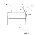
- FIG. 1 An electronic component mounting machine 150 of the second embodiment is shown in FIG.
- the electronic component mounting machine 150 of the second embodiment has almost the same configuration as the electronic component mounting machine 10 of the first embodiment except for the display device 152.
- the display device 152 will be described, and components having the same functions as those of the electronic component mounting machine 10 will be denoted by the same reference numerals, and description thereof will be omitted.
- the display device 152 of the electronic component mounting machine 150 is provided on the upper cover 90 and includes a display panel 154 and a moving device 156.
- the display panel 154 displays an image related to work contents of the electronic component mounting machine 150 on the display surface.
- the moving device 156 includes a guide rail 158 and an electromagnetic motor (not shown).
- the guide rail 158 is fixed to the front surface of the upper cover 90 at the lower end portion, is slightly bent rearward at the center portion, and the upper end portion extends above the upper cover 90.
- the display panel 154 is slidably held on the guide rail 158 and slides between the lower end portion and the upper end portion of the guide rail 158 by driving of the electromagnetic motor.
- the display panel 154 is held at the lower end portion of the guide rail 158 and may be described as a position (hereinafter referred to as “first position”) with the display surface facing the operator on the front side of the electronic component mounting machine 150. ) (The position indicated by the solid line in FIG. 4) and a position held at the upper end of the guide rail 158 and the display surface facing obliquely upward at a position above the first position (hereinafter referred to as “second position”). (The position indicated by the dotted line in FIG. 4).
- the electronic component mounting machine 150 performs an operation on the electronic component mounting machine 150 by displaying an image on the display panel 154 with the display panel 154 moved to the first position.
- the worker who is viewing can view the display image.
- an operator working on a work machine different from the electronic component mounting machine 150 can display An image can be visually recognized. That is, in the display device 152, the first state for allowing the worker who is working on the electronic component mounting machine 150 to visually recognize the work and the work machine different from the electronic component mounting machine 150 are operated.
- the state in which the image is displayed on the display panel 154 that has been moved to the first position is The state in which the image is displayed on the display panel 154 that is in the state 1 and moved to the second position is the second state.
- the display device 152 of the second embodiment can achieve the same effects as the display device 28 of the first embodiment.
- the electronic component mounting machine 10 is an example of a working machine.
- the display device 28 is an example of a display device.
- the display panel 100 is an example of a display panel.
- the rotation device 102 is an example of a moving mechanism.
- the conical mirror 104 is an example of a mirror.
- the display control unit 130 is an example of a display control device.
- the first display unit 132 is an example of a first display unit.
- the second display unit 134 is an example of a second display unit.
- the electronic component mounting machine 150 is an example of a work machine.
- the display device 152 is an example of a display device.
- the display panel 154 is an example of a display panel.
- the moving device 156 is an example of a moving function.
- this invention is not limited to the said Example, It is possible to implement in the various aspect which gave various change and improvement based on the knowledge of those skilled in the art.
- the conical mirror 104 having a radially curved mirror surface is employed, but it is possible to employ mirror mirrors having various curved shapes. is there.
- it is possible to adopt a mirror with a flat mirror surface instead of a curved mirror surface and it is possible to arrange a plurality of mirrors with a flat mirror surface radially. That is, it is possible to employ a polygonal mirror.
- a plurality of mirrors may be arranged so as to be a pair of mirrors, and the display image of the display panel 100 may be displayed on the plurality of mirrors.
- the character information can be displayed on the display panel 100 moved to the second position.
- blue is reflected on the mirror surface of the conical mirror 104 by causing the display surface of the display panel 100 to emit blue light.
- red light is reflected on the mirror surface of the conical mirror 104 by causing the display surface of the display panel 100 to emit red light.
- the display surface of the display panel 100 emits yellow light so that the mirror surface of the conical mirror 104 appears yellow. That is, the conical mirror 104 can function as a signal tower. In this way, even if only the color is displayed on the display panel 100 that has been moved to the second position, it is possible to provide a certain amount of information to the operator by projecting the color on the conical mirror 104. Become.
- the first state and the second state are states in which an image is displayed on the display panel 154.
- the display panel 154 In the first state, the display panel 154 is displayed.
- the image In the second state, the image can be projected on a screen or the like by a projector or the like. That is, the state where an image is displayed on the display panel 154 can be a first state, and the state where an image is projected on a projection unit such as a screen can be a second state.
Landscapes
- Engineering & Computer Science (AREA)
- Theoretical Computer Science (AREA)
- Human Computer Interaction (AREA)
- Physics & Mathematics (AREA)
- General Engineering & Computer Science (AREA)
- General Physics & Mathematics (AREA)
- Manufacturing & Machinery (AREA)
- Microelectronics & Electronic Packaging (AREA)
- Supply And Installment Of Electrical Components (AREA)
- User Interface Of Digital Computer (AREA)
Abstract
本発明の表示装置(28)では、表示パネル(100)が、表示面を電子部品装着機(10)の正面側を向けた第1の位置と、表示面を電子部品装着機(10)の上面において、上方を向けた第2の位置との間で移動可能とされている。また、第2の位置に移動された表示パネルに表示された画像が映る位置に、円錐鏡(104)が配設されている。このため、例えば、電子部品装着機から離れた位置で作業している作業者であっても、円錐鏡に映った画像を目視することが可能となる。これにより、電子部品装着機から離れた個所において作業を実行している作業者であっても、作業内容に関する画像等を認識することが可能となる。
Description
本発明は、作業機に設けられる表示装置に関するものである。
作業機に設けられる表示装置では、通常、作業機の側面に、表示パネルが配設され、その表示パネルの表示面に、作業機の作業内容に関する画像等が表示される。下記特許文献には、作業機に設けられた表示装置の一例が記載されている。
上記特許文献に記載の表示装置では、作業者は、表示パネルに表示された画像を目視することで、作業者は、作業内容等を認識することが可能となる。しかしながら、作業者は、通常、1台の作業機だけでなく、複数の作業機を管理する必要がある。このため、作業機から離れた個所において作業を実行している作業者は、表示パネルを目視できず、作業内容に関する画像等を認識できない虞がある。本発明は、そのような実情に鑑みてなされたものであり、作業機から離れた個所において作業を実行している作業者であっても、作業内容に関する画像等を認識可能な表示装置の提供を課題とする。
上記課題を解決するために、本発明の表示装置は、作業機に設けられ、画像を表示する表示パネルと、前記表示パネルに表示された画像が映る位置に配設された鏡とを備えることを特徴とする。
また、上記課題を解決するために、本発明の表示装置は、作業機に設けられる表示装置であって、前記表示装置が、前記作業機に対して作業を行っている作業者に視認させるための第1の状態と、前記作業機と異なる作業機に対して作業を行っている作業者に視認させるための第2の状態とで選択的に画像を表示することを特徴とする。
本発明に記載の表示装置では、表示パネルに表示された画像が鏡に映される。このため、例えば、鏡を作業機の上方に配設すれば、作業機から離れた位置で作業している作業者であっても、鏡に映った画像を目視することが可能となる。これにより、作業機から離れた個所において作業を実行している作業者であっても、作業内容に関する画像等を認識することが可能となる。
また、本発明に記載の表示装置では、作業機に対して作業を行っている作業者に視認させるための第1の状態と、その作業機と異なる作業機に対して作業を行っている作業者に視認させるための第2の状態とで選択的に画像が表示される。これにより、作業機から離れた個所において作業を実行している作業者であっても、第2の状態で表示された画像を目視し、作業内容に関する画像等を認識することが可能となる。
以下、本発明を実施するための形態として、本発明の実施例を、図を参照しつつ詳しく説明する。
<電子部品装着機の構成>
図1に、本発明の第1実施例の電子部品装着機10を示す。電子部品装着機10は、回路基板に対する電子部品の装着作業を実行するための装置である。電子部品装着機10は、搬送装置20と、装着ヘッド移動装置(以下、「移動装置」と略す場合がある)22と、装着ヘッド24と、供給装置26と、表示装置(図2参照)28とを備えている。
図1に、本発明の第1実施例の電子部品装着機10を示す。電子部品装着機10は、回路基板に対する電子部品の装着作業を実行するための装置である。電子部品装着機10は、搬送装置20と、装着ヘッド移動装置(以下、「移動装置」と略す場合がある)22と、装着ヘッド24と、供給装置26と、表示装置(図2参照)28とを備えている。
搬送装置20は、X軸方向に延びる1対のコンベアベルト30と、コンベアベルト30を周回させる電磁モータ(図3参照)32とを有している。回路基板34は、それら1対のコンベアベルト30によって支持され、電磁モータ32の駆動により、X軸方向に搬送される。また、搬送装置20は、基板保持装置(図3参照)36を有している。基板保持装置36は、コンベアベルト30によって支持された回路基板34を、所定の位置(図1での回路基板34が図示されている位置)において固定的に保持する。
移動装置22は、X軸方向スライド機構50とY軸方向スライド機構52とによって構成されている。X軸方向スライド機構50は、X軸方向に移動可能にベース54上に設けられたX軸スライダ56を有している。そのX軸スライダ56は、電磁モータ(図3参照)58の駆動により、X軸方向の任意の位置に移動する。また、Y軸方向スライド機構52は、X軸方向に直角なY軸方向に移動可能にX軸スライダ56の側面に設けられたY軸スライダ60を有している。そのY軸スライダ60は、電磁モータ(図3参照)62の駆動により、Y軸方向の任意の位置に移動する。そのY軸スライダ60には、装着ヘッド24が取り付けられている。このような構造により、装着ヘッド24は、移動装置22によってベース54上の任意の位置に移動する。
装着ヘッド24は、回路基板に対して電子部品を装着するものである。装着ヘッド24は、下端面に設けられた吸着ノズル70を有している。吸着ノズル70は、負圧エア,正圧エア通路を介して、正負圧供給装置(図3参照)76に通じている。吸着ノズル70は、負圧によって電子部品を吸着保持し、保持した電子部品を正圧によって離脱する。また、装着ヘッド24は、吸着ノズル70を昇降させるノズル昇降装置(図3参照)78を有している。そのノズル昇降装置78によって、装着ヘッド24は、保持する電子部品の上下方向の位置を変更する。なお、吸着ノズル70は、装着ヘッド24に着脱可能とされている。
供給装置26は、フィーダ型の供給装置であり、複数のテープフィーダ80を有している。テープフィーダ80は、テープ化部品を巻回させた状態で収容している。テープ化部品は、電子部品がテーピング化されたものである。そして、テープフィーダ80は、送り装置(図3参照)86によって、テープ化部品を送り出す。これにより、フィーダ型の供給装置26は、テープ化部品の送り出しによって、電子部品を供給位置において供給する。なお、テープフィーダ80は、ベース54に着脱可能とされており、電子部品の交換,電子部品の不足等に対応することが可能とされている。
表示装置28は、図2に示すように、ベース54を覆う上部カバー90に設けられている。表示装置28は、表示パネル100と、回動装置102と、円錐鏡104と、ブラケット106とを含む。表示パネル100は、表示面において電子部品装着機10の作業内容等に関する画像等を表示するものである。また、回動装置102は、支持アーム108を有しており、表示パネル100は、支持アーム108によって回動可能に上部カバー90に取り付けられている。
詳しくは、支持アーム108は、概して棒状をなし、一端部において、上部カバー90に回動可能に配設されている。その支持アーム108は、他端部が電子部品装着機10の正面側に向かって水平方向に延び出す姿勢(以下、「第1姿勢」と記載する場合がある)(図2での実線で示す姿勢)と、他端部が鉛直方向での上方に向かって延び出す姿勢(以下、「第2姿勢」と記載する場合がある)(図2での点線で示す姿勢)との間で回動する。つまり、支持アーム108が水平方向に延び出す姿勢から、上方に向かって90度回動する範囲が、支持アーム108の回動範囲となっている。また、回動装置102は、電磁モータ(図3参照)110を有しており、支持アーム108は、電磁モータ110の駆動により、回動する。なお、支持アーム108の他端部は、第1姿勢において、上部カバー90の正面から僅かに突出し、第2姿勢において、上部カバー90の上面から僅かに突出している。
また、支持アーム108は、他端部において、表示パネル100の表示面と反対側の面、つまり、裏面に固定されている。これにより、表示パネル100の表示面は、支持アーム108が第1姿勢となっている際に、電子部品装着機10の正面側、つまり、電子部品装着機10に対して作業を行う作業者を向いている。一方、支持アーム108が第2姿勢となっている際に、表示パネル100の表示面は、電子部品装着機10の上面において、上方を向いている。つまり、表示パネル100は、電子部品装着機10の正面側において表示面を作業者に向けた位置(以下、「第1の位置」と記載する場合がある)(図2での実線で示す位置)と、電子部品装着機10の上面において表示面を上方に向けた位置(以下、「第2の位置」と記載する場合がある)(図2での点線で示す位置)との間で移動する。
円錐鏡104は、概して円錐状をなし、円錐面が鏡面となっている。つまり、円錐鏡104の鏡面は、放射状に湾曲している。また、ブラケット106は、概してL字型をなし、L字型の一方の辺が支柱として機能し、電子部品装着機10の上部カバー90の上面に立設されている。そして、ブラケット106のL字型の他方の辺が、第2の位置に移動している表示パネル100の上方に向かって延び出している。そのブラケット106のL字型の他方の辺には、円錐鏡104が、頂点を下方に向けた姿勢で固定されている。つまり、円錐鏡104は、円錐面を下方に向けた姿勢で、第2の位置に移動している表示パネル100の上方に、ブラケット106によって保持されている。これにより、表示パネル100が第2の位置に移動することで、表示パネル100に表示される画像が、円錐鏡104に映る。なお、ブラケット106は、支柱として機能するL字型の一方の辺において伸縮可能となっている。これにより、円錐鏡104の上下方向の位置を変更することが可能となっている。
また、電子部品装着機10は、図3に示すように、制御装置120を備えている。制御装置120は、コントローラ122と、複数の駆動回路124と、制御回路126とを備えている。複数の駆動回路124は、上記電磁モータ32,58,62,110、基板保持装置36、正負圧供給装置76、ノズル昇降装置78、送り装置86に接続されている。コントローラ122は、CPU,ROM,RAM等を備え、コンピュータを主体とするものであり、複数の駆動回路124に接続されている。これにより、搬送装置20、移動装置22等の作動が、コントローラ122によって制御される。また、コントローラ122は、制御回路126にも接続されており、その制御回路126は、表示パネル100に接続されている。これにより、任意の画像が表示パネル100に表示される。
<電子部品装着機による装着作業>
電子部品装着機10では、上述した構成によって、搬送装置20に保持された回路基板34に対して、装着ヘッド24によって装着作業を行うことが可能とされている。具体的には、コントローラ122の指令により、回路基板34が作業位置まで搬送され、その位置において、回路基板34が、基板保持装置36によって固定的に保持される。また、テープフィーダ80は、コントローラ122の指令により、テープ化部品を送り出し、電子部品を供給位置において供給する。そして、装着ヘッド24が、コントローラ122の指令により、電子部品の供給位置の上方に移動し、吸着ノズル70によって電子部品を吸着保持する。続いて、装着ヘッド24は、コントローラ122の指令により、回路基板34の上方に移動し、保持している電子部品を回路基板上に装着する。
電子部品装着機10では、上述した構成によって、搬送装置20に保持された回路基板34に対して、装着ヘッド24によって装着作業を行うことが可能とされている。具体的には、コントローラ122の指令により、回路基板34が作業位置まで搬送され、その位置において、回路基板34が、基板保持装置36によって固定的に保持される。また、テープフィーダ80は、コントローラ122の指令により、テープ化部品を送り出し、電子部品を供給位置において供給する。そして、装着ヘッド24が、コントローラ122の指令により、電子部品の供給位置の上方に移動し、吸着ノズル70によって電子部品を吸着保持する。続いて、装着ヘッド24は、コントローラ122の指令により、回路基板34の上方に移動し、保持している電子部品を回路基板上に装着する。
<表示装置による作業内容の表示>
電子部品装着機10では、上述した手順に従って装着作業が実行される際には、実行中の作業に関する情報、電子部品装着機10の作動状態に関する情報、エラー等が発生した場合には、エラー内容,エラーの対処方法に関する情報、電子部品の補給,交換時には、電子部品に関する情報等を、作業者に報知する必要がある。このため、電子部品装着機10では、表示装置28によって、作業者に報知すべき情報に関する画像が表示パネル100に表示される。詳しくは、支持アーム108が第1姿勢となるように支持アーム108が回動され、表示パネル100が第1の位置に移動している際に、表示パネル100に画像が表示されると、電子部品装着機10の正面で作業している作業者は、画像を確認することが可能である。
電子部品装着機10では、上述した手順に従って装着作業が実行される際には、実行中の作業に関する情報、電子部品装着機10の作動状態に関する情報、エラー等が発生した場合には、エラー内容,エラーの対処方法に関する情報、電子部品の補給,交換時には、電子部品に関する情報等を、作業者に報知する必要がある。このため、電子部品装着機10では、表示装置28によって、作業者に報知すべき情報に関する画像が表示パネル100に表示される。詳しくは、支持アーム108が第1姿勢となるように支持アーム108が回動され、表示パネル100が第1の位置に移動している際に、表示パネル100に画像が表示されると、電子部品装着機10の正面で作業している作業者は、画像を確認することが可能である。
しかしながら、作業者は、電子部品装着機10だけでなく、他の作業機の確認等を行う必要があるため、電子部品装着機10から離れた位置で作業することが多い。このため、表示装置28では、電子部品装着機10に対して作業を行っている作業者に視認させるための第1の状態と、電子部品装着機10と異なる作業機に対して作業を行っている作業者に視認させるための第2の状態とで選択的に画像が表示される。詳しくは、装着作業実行時に、支持アーム108が第2姿勢となるように支持アーム108が回動され、表示パネル100が、第1の位置より上方の第2の位置に移動している。表示パネル100が第2の位置に移動している際に、表示パネル100に画像が表示されると、表示パネル100に表示された画像が、円錐鏡104に映る。円錐鏡104は、上述したように、電子部品装着機10の上部カバー90の上方に配設されており、電子部品装着機10から離れた個所から、円錐鏡104を確認することが可能である。これにより、電子部品装着機10から離れた個所で作業している作業者であっても、電子部品装着機10の作業内容を確認することが可能となる。なお、第1の位置に移動している表示パネル100に画像が表示された状態が、第1の状態であり、第2の位置に移動している表示パネル100に画像が表示された状態が、第2の状態である。
なお、円錐鏡104の鏡面は、湾曲しているため、表示パネル100に通常の画像が表示された場合には、円錐鏡104の鏡面に映った画像は歪み、作業者が、表示内容を認識できない。このため、表示パネル100が第2の位置に移動している場合には、加工された画像データに基づく画像が、表示パネル100に表示される。詳しくは、制御装置120のコントローラ122には、表示パネル100が第1の位置に移動している際に表示パネル100に表示される画像の画像データ(以下、「第1画像データ」と記載する場合がある)と、表示パネル100が第2の位置に移動している際に表示パネル100に表示される画像の画像データ(以下、「第2画像データ」と記載する場合がある)とが記憶されている。
第1画像データは、通常の画像を表示するための画像データ、つまり、表示パネル100に表示された画像(以下、「表示画像」と記載する場合がある)が、歪みが無く、作業者が認識できる画像の画像データであり、第1画像データに基づく画像が、表示パネル100に表示された場合には、その表示画像を作業者は認識することが可能である。一方、第2画像データは、第1画像データを加工した画像データであり、表示パネル100の表示画像が円錐鏡104に映った画像(以下、「反射画像」と記載する場合がある)が、歪みが無く、作業者が認識できる画像の画像データである。つまり、第2画像データに基づく画像が、表示パネル100に表示された場合には、表示画像は歪み、その表示画像を作業者は認識することができないが、第2画像データに基づく画像が、表示パネル100に表示され、表示画像が円錐鏡104に映された場合には、反射画像は、歪みが無く、その反射画像を作業者は認識することが可能である。このように、表示パネル100が第2の位置に移動している際には、第2画像データに基づく画像が、表示パネル100に表示されることで、作業者は、歪みの無い状態で反射画像を見ることが可能となる。
なお、コントローラ122に記憶されている第1画像データおよび、第2画像データは、ユーザが任意に変更することが可能となっている。つまり、ユーザが、表示装置28により表示したい画像の画像データ、つまり、表示画像用の第1画像データ、若しくは、反射画像用の第2画像データを作成し、作成した画像データを、コントローラ122に記憶させることが可能である。これにより、ユーザが、任意に表示画像、若しくは、反射画像を変更することが可能となる。
また、電子部品装着機10の上部カバー90の正面には、操作スイッチ(図示省略)が配設されており、その操作スイッチの操作により、支持アーム108が、第2姿勢から第1姿勢に回動する。これにより、作業者は、電子部品装着機10の正面において、表示パネル100を直接、確認することが可能となる。なお、表示パネル100が第1の位置に移動している際には、第1画像データに基づく画像が、表示パネル100に表示される。
また、コントローラ122は、図3に示すように、表示パネル100への画像の表示を制御するための表示制御部130を有している。そして、その表示制御部130は、第1表示部132と第2表示部134とを含む。第1表示部132は、表示パネル100が第1の位置に移動している際に、第1画像データに基づく画像を表示パネル100に表示させるための機能部である。一方、第2表示部134は、表示パネル100が第2の位置に移動している際に、第2画像データに基づく画像を表示パネル100に表示させるための機能部である。
<第2実施例>
第2実施例の電子部品装着機150を図4に示す。第2実施例の電子部品装着機150は、表示装置152を除いて、第1実施例の電子部品装着機10と殆ど同じ構成である。このため、表示装置152について、説明し、上記電子部品装着機10と同じ機能の構成要素については、同じ符号を用い、それらの説明は省略する。
第2実施例の電子部品装着機150を図4に示す。第2実施例の電子部品装着機150は、表示装置152を除いて、第1実施例の電子部品装着機10と殆ど同じ構成である。このため、表示装置152について、説明し、上記電子部品装着機10と同じ機能の構成要素については、同じ符号を用い、それらの説明は省略する。
電子部品装着機150の表示装置152は、上部カバー90に設けられており、表示パネル154と、移動装置156とを含む。表示パネル154は、表示面において電子部品装着機150の作業内容等に関する画像を表示するものである。また、移動装置156は、ガイドレール158と電磁モータ(図示省略)とを有している。ガイドレール158は、下端部において、上部カバー90の正面に固定されており、中央部において、後方に向かって僅かに屈曲し、上端部が、上部カバー90の上方に延び出している。表示パネル154は、ガイドレール158にスライド可能に保持されており、電磁モータの駆動により、ガイドレール158の下端部と上端部との間でスライドする。つまり、表示パネル154は、ガイドレール158の下端部において保持され、電子部品装着機150の正面側において表示面を作業者に向けた位置(以下、「第1の位置」と記載する場合がある)(図4での実線で示す位置)と、ガイドレール158の上端部において保持され、第1の位置より上方の位置において表示面を斜め上方に向けた位置(以下、「第2の位置」と記載する場合がある)(図4での点線で示す位置)との間で移動する。
このような構造において、電子部品装着機150では、第1の位置に表示パネル154を移動させた状態で、表示パネル154に画像を表示することで、電子部品装着機150に対して作業を行っている作業者が、表示画像を視認することが可能となる。一方、第2の位置に表示パネル154を移動させた状態で、表示パネル154に画像を表示することで、電子部品装着機150と異なる作業機に対して作業を行っている作業者が、表示画像を視認することが可能となる。つまり、表示装置152では、電子部品装着機150に対して作業を行っている作業者に視認させるための第1の状態と、電子部品装着機150と異なる作業機に対して作業を行っている作業者に視認させるための第2の状態とで選択的に画像が表示パネル154に表示される際に、第1の位置に移動している表示パネル154に画像が表示された状態が、第1の状態となり、第2の位置に移動している表示パネル154に画像が表示された状態が、第2の状態となる。これにより、第2実施例の表示装置152においても、第1実施例の表示装置28と同様の効果を奏することが可能となる。
ちなみに、上記実施例において、電子部品装着機10は、作業機の一例である。表示装置28は、表示装置の一例である。表示パネル100は、表示パネルの一例である。回動装置102は、移動機構の一例である。円錐鏡104は、鏡の一例である。表示制御部130は、表示制御装置の一例である。第1表示部132は、第1表示部の一例である。第2表示部134は、第2表示部の一例である。電子部品装着機150は、作業機の一例である。表示装置152は、表示装置の一例である。表示パネル154は、表示パネルの一例である。移動装置156は、移動機能の一例である。
なお、本発明は、上記実施例に限定されるものではなく、当業者の知識に基づいて種々の変更、改良を施した種々の態様で実施することが可能である。具体的には、例えば、上記第1実施例の表示装置28では、放射状に湾曲した鏡面の円錐鏡104が採用されているが、種々の形状に湾曲した鏡面の鏡を採用することが可能である。また、湾曲した鏡面でなく、平坦な鏡面の鏡を採用することも可能であり、複数の平坦な鏡面の鏡を放射状に配設することもの可能である。つまり、多角錘状の鏡を採用することが可能である。さらに言えば、複数の鏡を、合わせ鏡となるように配設し、表示パネル100の表示画像を複数の鏡に映してもよい。
また、第2の位置に移動している表示パネル100には、文字情報だけでなく、色のみを表示することも可能である。例えば、電子部品装着機10が正常に作動している際には、表示パネル100の表示面を青色に発光させることで、円錐鏡104の鏡面には、青色が映る。また、電子部品装着機10に異常が発生している際には、表示パネル100の表示面を赤色に発光させることで、円錐鏡104の鏡面には、赤色が映る。さらに、電子部品の交換,補給時には、表示パネル100の表示面を黄色に発光させることで、円錐鏡104の鏡面には、黄色が映る。つまり、円錐鏡104をシグナルタワーとして機能させることが可能である。このように、第2の位置に移動している表示パネル100に色のみを表示させることでも、その色を円錐鏡104に映すことで、作業者に、ある程度の情報を提供することが可能となる。
また、上記第2実施例の表示装置152では、第1の状態および、第2の状態が、表示パネル154に画像が表示された状態とされているが、第1の状態において、表示パネル154に画像を表示し、第2の状態において、画像をスクリーン等にプロジェクター等によって投映することが可能である。つまり、表示パネル154に画像が表示された状態を、第1の状態とし、スクリーン等の投映部に画像が投映された状態を、第2の状態とすることが可能である。
10:電子部品装着機(作業機) 28:表示装置 100:表示パネル 102:回動装置(移動機構) 104:円錐鏡(鏡) 130:表示制御部 132:第1表示部 134:第2表示部 150:電子部品装着機(作業機) 152:表示装置 154:表示パネル 156:移動装置(移動機構)
Claims (7)
- 作業機に設けられ、画像を表示する表示パネルと、
前記表示パネルに表示された画像が映る位置に配設された鏡と
を備えることを特徴とする表示装置。 - 前記表示装置が、
前記表示パネルを第1の位置と第2の位置との間で移動させる移動機構を備え、
前記鏡が、
前記移動機構により前記第2の位置に移動された前記表示パネルに表示された画像が映る位置に配設されることを特徴とする請求項1に記載の表示装置。 - 前記表示装置が、
前記移動機構により前記第1の位置に移動された前記表示パネルに、所定の画像データに基づく画像を表示させる第1表示部と、前記移動機構により前記第2の位置に移動された前記表示パネルに、前記鏡の鏡面に前記所定の画像データに基づく画像が映るように変換された画像データに基づく画像を表示させる第2表示部とを有する表示制御装置を備えることを特徴とする請求項2に記載の表示装置。 - 前記鏡の鏡面が、湾曲していることを特徴とする請求項1ないし請求項3のいずれか1つに記載の表示装置。
- 前記鏡の鏡面が、放射状に配設されることを特徴とする請求項1ないし請求項4のいずれか1つに記載の表示装置。
- 作業機に設けられる表示装置であって、
前記表示装置が、
前記作業機に対して作業を行っている作業者に視認させるための第1の状態と、前記作業機と異なる作業機に対して作業を行っている作業者に視認させるための第2の状態とで選択的に画像を表示する表示装置。 - 前記表示装置が、
画像を表示する表示パネルと、
前記表示パネルを、第1の位置と、その第1の位置より上方に位置する第2の位置との間で移動させる移動機構と
を備え、
前記第1の状態が、
前記移動機構により前記第1の位置に移動された前記表示パネルに画像を表示させる状態であり、
前記第2の状態が、
前記移動機構により前記第2の位置に移動された前記表示パネルに画像を表示させる状態であることを特徴とする請求項6に記載の表示装置。
Priority Applications (2)
| Application Number | Priority Date | Filing Date | Title |
|---|---|---|---|
| JP2017513873A JP6666903B2 (ja) | 2015-04-22 | 2015-04-22 | 表示装置 |
| PCT/JP2015/062195 WO2016170609A1 (ja) | 2015-04-22 | 2015-04-22 | 表示装置 |
Applications Claiming Priority (1)
| Application Number | Priority Date | Filing Date | Title |
|---|---|---|---|
| PCT/JP2015/062195 WO2016170609A1 (ja) | 2015-04-22 | 2015-04-22 | 表示装置 |
Publications (1)
| Publication Number | Publication Date |
|---|---|
| WO2016170609A1 true WO2016170609A1 (ja) | 2016-10-27 |
Family
ID=57143176
Family Applications (1)
| Application Number | Title | Priority Date | Filing Date |
|---|---|---|---|
| PCT/JP2015/062195 Ceased WO2016170609A1 (ja) | 2015-04-22 | 2015-04-22 | 表示装置 |
Country Status (2)
| Country | Link |
|---|---|
| JP (1) | JP6666903B2 (ja) |
| WO (1) | WO2016170609A1 (ja) |
Citations (4)
| Publication number | Priority date | Publication date | Assignee | Title |
|---|---|---|---|---|
| JPH05150233A (ja) * | 1991-12-02 | 1993-06-18 | Sharp Corp | 液晶表示装置 |
| JPH11271745A (ja) * | 1998-03-25 | 1999-10-08 | Rohm Co Ltd | 表示装置 |
| JP2004186654A (ja) * | 2002-12-04 | 2004-07-02 | Fuji Mach Mfg Co Ltd | 生産作業装置 |
| JP2004193196A (ja) * | 2002-12-09 | 2004-07-08 | Yamagata Casio Co Ltd | 電子部品搭載装置の操作入力用表示画面表示方法 |
Family Cites Families (1)
| Publication number | Priority date | Publication date | Assignee | Title |
|---|---|---|---|---|
| JP5402730B2 (ja) * | 2010-03-08 | 2014-01-29 | パナソニック株式会社 | 電子部品実装用装置および電子部品実装用装置の操作方法 |
-
2015
- 2015-04-22 JP JP2017513873A patent/JP6666903B2/ja active Active
- 2015-04-22 WO PCT/JP2015/062195 patent/WO2016170609A1/ja not_active Ceased
Patent Citations (4)
| Publication number | Priority date | Publication date | Assignee | Title |
|---|---|---|---|---|
| JPH05150233A (ja) * | 1991-12-02 | 1993-06-18 | Sharp Corp | 液晶表示装置 |
| JPH11271745A (ja) * | 1998-03-25 | 1999-10-08 | Rohm Co Ltd | 表示装置 |
| JP2004186654A (ja) * | 2002-12-04 | 2004-07-02 | Fuji Mach Mfg Co Ltd | 生産作業装置 |
| JP2004193196A (ja) * | 2002-12-09 | 2004-07-08 | Yamagata Casio Co Ltd | 電子部品搭載装置の操作入力用表示画面表示方法 |
Also Published As
| Publication number | Publication date |
|---|---|
| JP6666903B2 (ja) | 2020-03-18 |
| JPWO2016170609A1 (ja) | 2018-02-08 |
Similar Documents
| Publication | Publication Date | Title |
|---|---|---|
| CN107872951B (zh) | 供给器配置支援系统以及供给器配置支援方法 | |
| JP6680545B2 (ja) | 作業実行装置、および可視光通信システム | |
| JP5065706B2 (ja) | スクリーン印刷機 | |
| JP7393257B2 (ja) | 干渉確認装置及びそれを備えた実装機 | |
| WO2018163384A1 (ja) | 供給部品検査装置 | |
| WO2016046967A1 (ja) | メンテナンス案内システム及びメンテナンス案内方法 | |
| JP6666903B2 (ja) | 表示装置 | |
| JP6283681B2 (ja) | 作業機 | |
| JP2023129769A (ja) | 部品実装装置および部品実装方法 | |
| JP7664553B2 (ja) | 部品搭載装置 | |
| JP6016683B2 (ja) | 電子部品装着装置における装着ヘッドの高さ検出方法及び電子部品装着装置 | |
| JP5877211B2 (ja) | 電子部品供給装置 | |
| JP5665642B2 (ja) | 電子部品実装装置 | |
| JP2017183587A (ja) | 部品装着機 | |
| JP6110172B2 (ja) | 電子部品装着装置 | |
| JPWO2019053897A1 (ja) | 実装システム | |
| JP2008034595A (ja) | 電子部品装着装置 | |
| JP4730323B2 (ja) | 電子部品実装用装置および電子部品実装用装置における操作パネルの文字表示方法 | |
| JPWO2016117085A1 (ja) | 対基板作業機 | |
| JP7292735B2 (ja) | インクジェットプリンタのヘッド支持装置、インクジェットプリンタシステム | |
| KR102149278B1 (ko) | 부품 실장기 | |
| JP4908375B2 (ja) | 電子部品装着方法及び電子部品装着装置 | |
| JP4734152B2 (ja) | 部品搭載プログラム作成システム | |
| JP5905732B2 (ja) | 対基板作業システム | |
| JP2023138647A (ja) | 部品装着システム |
Legal Events
| Date | Code | Title | Description |
|---|---|---|---|
| 121 | Ep: the epo has been informed by wipo that ep was designated in this application |
Ref document number: 15889848 Country of ref document: EP Kind code of ref document: A1 |
|
| ENP | Entry into the national phase |
Ref document number: 2017513873 Country of ref document: JP Kind code of ref document: A |
|
| NENP | Non-entry into the national phase |
Ref country code: DE |
|
| 122 | Ep: pct application non-entry in european phase |
Ref document number: 15889848 Country of ref document: EP Kind code of ref document: A1 |