WO2016167178A1 - 廃液処理方法および廃液処理装置 - Google Patents
廃液処理方法および廃液処理装置 Download PDFInfo
- Publication number
- WO2016167178A1 WO2016167178A1 PCT/JP2016/061412 JP2016061412W WO2016167178A1 WO 2016167178 A1 WO2016167178 A1 WO 2016167178A1 JP 2016061412 W JP2016061412 W JP 2016061412W WO 2016167178 A1 WO2016167178 A1 WO 2016167178A1
- Authority
- WO
- WIPO (PCT)
- Prior art keywords
- waste liquid
- polyacid
- liquid treatment
- chemical solution
- chemical
- Prior art date
- Legal status (The legal status is an assumption and is not a legal conclusion. Google has not performed a legal analysis and makes no representation as to the accuracy of the status listed.)
- Ceased
Links
Images


Classifications
-
- C—CHEMISTRY; METALLURGY
- C02—TREATMENT OF WATER, WASTE WATER, SEWAGE, OR SLUDGE
- C02F—TREATMENT OF WATER, WASTE WATER, SEWAGE, OR SLUDGE
- C02F1/00—Treatment of water, waste water, or sewage
- C02F1/72—Treatment of water, waste water, or sewage by oxidation
-
- C—CHEMISTRY; METALLURGY
- C02—TREATMENT OF WATER, WASTE WATER, SEWAGE, OR SLUDGE
- C02F—TREATMENT OF WATER, WASTE WATER, SEWAGE, OR SLUDGE
- C02F1/00—Treatment of water, waste water, or sewage
- C02F1/58—Treatment of water, waste water, or sewage by removing specified dissolved compounds
- C02F1/62—Heavy metal compounds
-
- H—ELECTRICITY
- H10—SEMICONDUCTOR DEVICES; ELECTRIC SOLID-STATE DEVICES NOT OTHERWISE PROVIDED FOR
- H10P—GENERIC PROCESSES OR APPARATUS FOR THE MANUFACTURE OR TREATMENT OF DEVICES COVERED BY CLASS H10
- H10P72/00—Handling or holding of wafers, substrates or devices during manufacture or treatment thereof
- H10P72/04—Apparatus for manufacture or treatment
- H10P72/0402—Apparatus for fluid treatment
- H10P72/0418—Apparatus for fluid treatment for etching
- H10P72/0422—Apparatus for fluid treatment for etching for wet etching
- H10P72/0424—Apparatus for fluid treatment for etching for wet etching using mainly spraying means, e.g. nozzles
-
- H—ELECTRICITY
- H10—SEMICONDUCTOR DEVICES; ELECTRIC SOLID-STATE DEVICES NOT OTHERWISE PROVIDED FOR
- H10P—GENERIC PROCESSES OR APPARATUS FOR THE MANUFACTURE OR TREATMENT OF DEVICES COVERED BY CLASS H10
- H10P72/00—Handling or holding of wafers, substrates or devices during manufacture or treatment thereof
- H10P72/04—Apparatus for manufacture or treatment
- H10P72/0448—Apparatus for applying a liquid, a resin, an ink or the like
-
- C—CHEMISTRY; METALLURGY
- C02—TREATMENT OF WATER, WASTE WATER, SEWAGE, OR SLUDGE
- C02F—TREATMENT OF WATER, WASTE WATER, SEWAGE, OR SLUDGE
- C02F1/00—Treatment of water, waste water, or sewage
- C02F1/52—Treatment of water, waste water, or sewage by flocculation or precipitation of suspended impurities
-
- C—CHEMISTRY; METALLURGY
- C02—TREATMENT OF WATER, WASTE WATER, SEWAGE, OR SLUDGE
- C02F—TREATMENT OF WATER, WASTE WATER, SEWAGE, OR SLUDGE
- C02F2101/00—Nature of the contaminant
- C02F2101/10—Inorganic compounds
-
- C—CHEMISTRY; METALLURGY
- C02—TREATMENT OF WATER, WASTE WATER, SEWAGE, OR SLUDGE
- C02F—TREATMENT OF WATER, WASTE WATER, SEWAGE, OR SLUDGE
- C02F2103/00—Nature of the water, waste water, sewage or sludge to be treated
- C02F2103/34—Nature of the water, waste water, sewage or sludge to be treated from industrial activities not provided for in groups C02F2103/12 - C02F2103/32
- C02F2103/346—Nature of the water, waste water, sewage or sludge to be treated from industrial activities not provided for in groups C02F2103/12 - C02F2103/32 from semiconductor processing, e.g. waste water from polishing of wafers
-
- C—CHEMISTRY; METALLURGY
- C02—TREATMENT OF WATER, WASTE WATER, SEWAGE, OR SLUDGE
- C02F—TREATMENT OF WATER, WASTE WATER, SEWAGE, OR SLUDGE
- C02F2303/00—Specific treatment goals
- C02F2303/18—Removal of treatment agents after treatment
-
- H—ELECTRICITY
- H10—SEMICONDUCTOR DEVICES; ELECTRIC SOLID-STATE DEVICES NOT OTHERWISE PROVIDED FOR
- H10P—GENERIC PROCESSES OR APPARATUS FOR THE MANUFACTURE OR TREATMENT OF DEVICES COVERED BY CLASS H10
- H10P72/00—Handling or holding of wafers, substrates or devices during manufacture or treatment thereof
- H10P72/04—Apparatus for manufacture or treatment
- H10P72/0402—Apparatus for fluid treatment
Definitions
- the present invention relates to a waste liquid processing method and a waste liquid processing apparatus for removing a metal contained in a chemical solution such as an etching solution used for processing a semiconductor substrate and regenerating the chemical solution.
- the back-end process (BEOL: Back End Of The Line) uses an etching method, and various etching solutions have been developed. Typically, since the etching solution dissolves the metal, the etching solution containing the metal is disposed as a waste solution.
- Patent Document 1 uses a carrier having a chelate-forming group for a metal dissolved in the etching solution. A technique for regenerating the etching solution by supplementing has been proposed.
- the present invention has been made in view of the above problems, and an object of the present invention is to provide a waste liquid treatment method and a waste liquid treatment apparatus that can regenerate the chemical liquid by removing the metal contained in the chemical liquid.
- a first aspect of the present invention is a waste liquid processing method for removing a metal contained in a chemical used for processing a semiconductor substrate, and a recovery step for recovering the chemical used for processing the semiconductor substrate. And a removal step of removing the metal from the chemical solution by mixing the polyacid with the chemical solution recovered in the recovery step and taking the metal contained in the chemical solution into the polyacid.
- the second aspect is the waste liquid treatment method according to the first aspect, wherein the polyacid is a deficient complex having a deficient site.
- the third aspect is the waste liquid treatment method according to the second aspect, wherein the chemical liquid recovered in the recovery step and the polyacid are reacted at a pH value of 2 to 3, thereby being contained in the chemical liquid.
- the metal is taken into the polyacid deficient site.
- the fourth aspect is the waste liquid treatment method according to the third aspect, wherein a counter cation is added to a mixed solution of the polyacid incorporating metal and the chemical solution to form a salt of the polyacid and the counter cation.
- a precipitation step for precipitation is further provided.
- the fifth aspect further includes a recycling step of reusing the chemical solution obtained by removing the precipitate generated in the precipitation step from the mixed solution in the processing of the semiconductor substrate in the waste liquid treatment method according to the fourth aspect.
- a waste liquid processing apparatus for removing a metal contained in a chemical solution used for processing a semiconductor substrate, a substrate processing unit that supplies the chemical solution to the semiconductor substrate and performs substrate processing, and the substrate processing unit.
- a storage unit that collects and stores the discharged used chemical solution, and a polyacid supply unit that supplies polyacid to the storage unit in which the used chemical solution is stored.
- the polyacid is a deficient complex having a deficient site.
- the eighth aspect further includes a pH adjusting unit that adjusts the pH value of the mixed liquid of the chemical solution and the polyacid stored in the storage unit to 2 to 3 in the waste liquid treatment apparatus according to the seventh aspect. .
- the ninth aspect further includes a cation introduction unit for introducing a counter cation into the mixed liquid of the chemical solution and the polyacid stored in the storage unit in the waste liquid treatment apparatus according to the eighth aspect.
- the tenth aspect further includes a reflux unit in the waste liquid treatment apparatus according to the ninth aspect, wherein the chemical solution obtained by removing the precipitate generated by introducing the counter cation from the mixed solution is refluxed to the substrate processing unit.
- the chemical liquid is mixed with the chemical liquid used for the treatment of the semiconductor substrate, and the metal contained in the chemical liquid is taken into the polyacid, thereby the chemical liquid.
- the chemical solution can be regenerated by removing the metal from the container.
- the chemical liquid is supplied to the used chemical liquid discharged from the substrate processing unit that supplies the chemical liquid to the semiconductor substrate and performs the substrate processing.
- FIG. 1 is a diagram showing an overall schematic configuration of a waste liquid treatment apparatus according to the present invention.
- the waste liquid treatment apparatus 1 removes the metal contained in the chemical liquid used for processing the semiconductor substrate W, and regenerates / reuses the chemical liquid.
- the waste liquid processing apparatus 1 includes, as main elements, a substrate processing unit 10 that performs chemical processing on the semiconductor substrate W, a storage tank 20 that collects and stores the chemical discharged from the substrate processing unit 10, and a polyacid in the storage tank 20. And a reflux mechanism 60 that refluxes the chemical solution regenerated by removing the metal to the substrate processing unit 10.
- the waste liquid treatment apparatus 1 includes a cation charging unit 40 that inputs counter cations into the storage tank 20 and a pH adjusting unit 50 that adjusts the pH value of the solution in the storage tank 20. Furthermore, the waste liquid treatment apparatus 1 includes a control unit 90 that controls each mechanism unit of the apparatus and manages the entire apparatus.
- the control unit 90 stores a CPU that is a circuit that performs various arithmetic processes, a ROM that is a read-only memory that stores basic programs, a RAM that is a readable and writable memory that stores various information, control software, data, and the like. It is configured with a magnetic disk.
- a CPU that is a circuit that performs various arithmetic processes
- a ROM that is a read-only memory that stores basic programs
- a RAM that is a readable and writable memory that stores various information, control software, data, and the like. It is configured with a magnetic disk.
- the substrate processing unit 10 is a single-wafer type apparatus that supplies a chemical solution to the semiconductor substrate W and performs a predetermined surface treatment, and includes a discharge nozzle 11, a spin chuck 12, a cup 13, and the like.
- the chemical solution for example, a chemical solution obtained by adding a buffer or a preservative to an aqueous solution of HF or NH 4 F base is used as the etching solution, and the substrate processing unit 10 performs etching processing on the surface of the semiconductor substrate W. Done.
- the chemical solution is discharged from the discharge nozzle 11 onto the surface of the semiconductor substrate W held on the spin chuck 12 to advance the etching process.
- the etching process may be performed while rotating the semiconductor substrate W by the spin chuck 12 as necessary. In this case, the chemical solution scattered from the rotating semiconductor substrate W is received by the cup 13 and collected.
- the chemical used for the surface treatment of the semiconductor substrate W in the substrate processing unit 10 is collected in the storage tank 20 through the waste liquid line 15.
- the storage tank 20 stores used chemicals.
- the used chemical solution contains metal components (ions) dissolved by the etching process in the substrate processing unit 10.
- the type of metal contained in the used chemical solution depends on the type of thin film formed on the semiconductor substrate W that has been subjected to the etching process in the substrate processing unit 10. For example, titanium (Ti) or Copper (Cu) or the like is dissolved.
- the polyacid supply unit 30 supplies polyacid to the storage tank 20.
- a polyacid is an anionic species formed by condensation of an oxo acid.
- An oxo acid is a compound in which a hydroxyl group (—OH) and an oxo group ( ⁇ O) are bonded to an atom, and the hydroxyl group gives an acidic proton.
- the carbon (C) oxo acid is carbonic acid
- the sulfur (S) oxo acid is sulfuric acid
- the transition metal oxo acid is called a metal oxo acid.
- a polyacid is produced by condensation of a metal oxo acid containing a metal, and can therefore be regarded as a molecular ionic species of a metal oxide, and is also referred to as polyoxometalate (POM).
- POM polyoxometalate
- the basic unit constituting the polyacid is a polyhedron such as a tetrahedron, a quadrangular pyramid, an octahedron or the like formed by coordination of 4 to 6 oxide ions (O 2 ⁇ ) to transition metal ions.
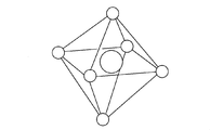
- FIG. 2 is a diagram illustrating an example of a basic structure of a polyacid.
- FIG. 2 shows an MO 6 octahedron which is a basic structure of a typical polyacid.
- transition metal ions are present at the center of gravity of the regular octahedron.
- Transition metal (M) ions located at the center of gravity of the MO 6 octahedron typically have molybdenum (Mo 6+ ), vanadium (V 5+ ), tungsten (W 6+ ), niobium (Nb 5+ ), tantalum (Ta 5+ ). ) Etc. Six oxide ions are coordinated at the apex position of the regular octahedron so as to surround the transition metal ion, thereby forming the MO 6 octahedron.
- a polynuclear complex formed by condensing a large number of such polyhedrons and sharing ridges and vertices is a polyacid.
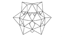
- 3 and 4 are diagrams showing the structures of typical polyacids.
- FIG. 3 shows a Keggin type structure represented by [XM 12 O 40 ] n- .
- FIG. 4 shows a Dawson type structure represented by [X 2 M 18 O 62 ] n- .
- X Metal
- the core metal (X) is, for example, silicon (Si), phosphorus (P), sulfur (S), or the like.
- the polyacid having such a structure has a characteristic that it is a strong acid comparable to sulfuric acid and hydrochloric acid but has low metal corrosiveness and additionally has redox properties. Polyacids exhibit high solubility in water and polar solvents, but the polyacid structure is maintained even in solution. Furthermore, the polyacid has an important characteristic that it can exist stably in a solution even as a deficient complex in which one or two polyhedrons as basic units are lost. For example, even a structure in which one or two MO 6 octahedrons are missing from the polyacid having the structure shown in FIGS. 3 and 4 can stably exist in a solution having a pH value of 2 to 7.
- the polyacid deficient complex can incorporate an oxo acid of a different metal (a metal different from the metals X and M constituting the polyacid) into the deficient site.
- a part of the metal M constituting the polyacid can be replaced with a different metal.
- the present invention has been completed with a focus on such properties of polyacids.
- the polyacid supply unit 30 supplies a polyacid of a deficient complex having a deficient site to the storage tank 20.
- the polyacid supply unit 30 includes a polyacid tank 31 and a supply pump, a valve, etc. (not shown).
- the polyacid tank 31 stores a deficient complex polyacid solution prepared in advance.
- the pH value of this solution is 2 to 7 so that the deficient complex polyacid can stably exist.
- the polyacid supply unit 30 supplies the polyacid solution of the deficient complex to the storage tank 20 in which the used chemical solution is stored.
- the pH adjusting unit 50 adjusts the pH value of the mixed solution to 2 to 3. Specifically, the pH adjusting unit 50 adjusts the pH value of the mixed solution to 2 to 3 by introducing a pH adjusting agent (for example, an acidic solution) into the storage tank 20. If the pH value of the mixed solution of the used chemical solution stored in the storage tank 20 and the polyacid of the deficient complex is 2 to 3, the metal ions contained in the chemical solution are converted into polyacids as oxo acids. The reaction taken into the defect site proceeds. As a result, the metal is removed from the used chemical solution discharged from the substrate processing unit 10.
- a pH adjusting agent for example, an acidic solution
- the solution of the polyacid is a strong acid and the chemical solution used in the substrate processing unit 10 is also acidic
- the mixed solution of the used chemical solution and the polyacid is used without special pH value adjustment.
- the pH value of itself may be within a range of 2 to 3.
- the pH adjusting unit 50 does not adjust the pH in the storage tank 20. Even if pH adjustment is not performed, if the pH value of the mixture of the used chemical and polyacid is 2 to 3, the metal ions contained in the chemical are taken into the polyacid deficient site as oxo acids. The reaction proceeds.
- a mixed solution of the polyacid that has taken in the metal and the chemical solution from which the metal has been removed is stored in the storage tank 20. Will be stored.
- the cation introduction unit 40 introduces a counter cation of a polyacid that is an anionic species into the mixed solution.
- the counter cation for example, n-Bu 4 NBr can be used.
- the cation introduction unit 40 introduces the counter cation into the storage tank 20
- the polyacid that has taken in the metal and the counter cation react to precipitate as a salt.
- the reflux mechanism 60 includes a reflux pipe 61, removal valves 62 a and 62 b, removal filters 63 a and 63 b, a main valve 64, a reflux pump 65, and a main filter 66.
- the proximal end side of the reflux pipe 61 is connected to the storage tank 20, and the distal end side is connected to the discharge nozzle 11.
- the reflux pipe 61 is bifurcated in the middle of the path, and a removal valve 62a and a removal filter 63a are provided on one side, and a removal valve 62b and a removal filter 63b are provided on the other side.
- the main valve 64, the recirculation pump 65, and the main filter 66, which are the remaining elements, are all inserted in a path where the bifurcated recirculation pipe 61 is rejoined.
- the removal filter 63a and the removal filter 63b are used alternatively. That is, one of the removal valve 62a and the removal valve 62b is selectively opened. If the removal valve 62a is opened while the removal valve 62b is closed while the main valve 64 is opened and the reflux pump 65 is operating, the liquid mixture containing the precipitate in the storage tank 20 passes through the removal filter 63a. Will be. At this time, the precipitate containing the polyacid that has taken in the metal is removed from the mixed solution by the removal filter 63a.
- the removal valve 62b is opened while the removal valve 62a is closed while the main valve 64 is opened and the reflux pump 65 is operating, the mixed liquid containing the precipitate in the storage tank 20 is removed by the removal filter 63b. Will pass. At this time, the precipitate containing the polyacid that has taken in the metal is removed from the mixed solution by the removal filter 63b.
- the removal filters 63a and 63b are filtration filters that filter the precipitate from the liquid containing the precipitate, clogging occurs in a relatively short time. For this reason, the removal filter 63a and the removal filter 63b are used alternatively. By replacing the removal filter 63b while using the removal filter 63a, and replacing the removal filter 63a while using the removal filter 63b, it is possible to prevent clogging of the piping due to clogging of the filter. Can do. It should be noted that the precipitates collected by the used removal filters 63a and 63b are recovered, and the polyacid is regenerated and reused by removing the metal from the precipitates using an oxidation-reduction reaction. May be.
- the removal filter 63a or the removal filter 63b By passing through the removal filter 63a or the removal filter 63b, the precipitate containing the polyacid that has taken in the metal from the mixed solution is removed, and the chemical solution is regenerated.
- the regenerated chemical solution is supplied to the discharge nozzle 11 of the substrate processing unit 10 by the reflux pump 65 and is reused by being discharged from the discharge nozzle 11 to the semiconductor substrate W.
- a polyacid of a deficient complex having a defect site is mixed with a used drug solution containing a metal, and the pH value of the mixed solution is set to 2 to 3, whereby the polyacid deficiency site is added to the drug solution. Taking in molten metal. Thereby, the metal contained in the chemical solution during the processing of the semiconductor substrate W can be removed and the chemical solution can be regenerated. There are some expensive chemicals used in the substrate processing unit 10, and if the metal can be regenerated by removing the used chemicals, the chemicals can be reused repeatedly. An increase in processing cost can be suppressed.
- the chemical liquid used in the substrate processing unit 10 is the etching liquid.
- the chemical liquid is not limited to this and may be other types of chemical liquids such as a polymer removing liquid. The more expensive the chemical used, the greater the effect of regenerating and reusing the chemical.
- the substrate processing unit 10 is not limited to a single-wafer type that processes the semiconductor substrates W one by one, but performs a surface treatment by immersing a plurality of semiconductor substrates W in a chemical solution stored in a processing tank.
- a batch processing unit may be used. Even if the substrate processing unit 10 is a batch type processing unit, the same effect can be obtained by regenerating the chemical solution discharged from the processing tank in the same manner as in the above embodiment.
- the polyacid and the counter cation were directly injected
- a dedicated sedimentation tank for separation and recovery may be provided.
- titanium and copper were contained in the chemical
- the metal used as the object of removal by this invention is other than tungsten (W), tantalum ( Ta), ruthenium (Ru), cobalt (Co), or the like may be used.
- an ion exchange filter may be used for the removal filters 63a and 63b, and the polyacid incorporating the metal may be deposited on the removal filters 63a and 63b and separated from the chemical solution.
- the present invention is suitable for a technique for removing a metal dissolved in a chemical solution during the surface treatment of a semiconductor substrate and regenerating and reusing the chemical solution.
Landscapes
- Life Sciences & Earth Sciences (AREA)
- Hydrology & Water Resources (AREA)
- Engineering & Computer Science (AREA)
- Environmental & Geological Engineering (AREA)
- Water Supply & Treatment (AREA)
- Chemical & Material Sciences (AREA)
- Organic Chemistry (AREA)
- Weting (AREA)
- Removal Of Specific Substances (AREA)
Abstract
Description
10 基板処理部
20 貯留タンク
30 ポリ酸供給部
40 カチオン投入部
50 pH調整部
60 還流機構
63a,63b 除去フィルタ
90 制御部
W 半導体基板
Claims (10)
- 半導体基板の処理に使用した薬液に含まれる金属を除去する廃液処理方法であって、
半導体基板の処理に使用された薬液を回収する回収工程と、
前記回収工程にて回収された薬液にポリ酸を混合し、当該薬液中に含まれている金属をポリ酸に取り込むことによって当該薬液から金属を除去する除去工程と、
を備える廃液処理方法。 - 請求項1記載の廃液処理方法において、
前記ポリ酸は、欠損部位を有する欠損型錯体である廃液処理方法。 - 請求項2記載の廃液処理方法において、
前記回収工程にて回収された薬液とポリ酸とをpH値2~3で反応させることによって、当該薬液中に含まれている金属をポリ酸の欠損部位に取り込む廃液処理方法。 - 請求項3記載の廃液処理方法において、
金属を取り込んだポリ酸と前記薬液との混合液にカウンターカチオンを投入して当該ポリ酸と当該カウンターカチオンとの塩を沈殿させる沈殿工程をさらに備える廃液処理方法。 - 請求項4記載の廃液処理方法において、
前記混合液から前記沈殿工程にて生成した沈殿物を取り除いた薬液を半導体基板の処理に再利用する再利用工程をさらに備える廃液処理方法。 - 半導体基板の処理に使用した薬液に含まれる金属を除去する廃液処理装置であって、
半導体基板に薬液を供給して基板処理を行う基板処理部と、
前記基板処理部から排出された使用済みの薬液を回収して貯留する貯留部と、
使用済みの薬液が貯留された前記貯留部にポリ酸を供給するポリ酸供給部と、
を備える廃液処理装置。 - 請求項6記載の廃液処理装置において、
前記ポリ酸は、欠損部位を有する欠損型錯体である廃液処理装置。 - 請求項7記載の廃液処理装置において、
前記貯留部に貯留された薬液とポリ酸との混合液のpH値を2~3に調整するpH調整部をさらに備える廃液処理装置。 - 請求項8記載の廃液処理装置において、
前記貯留部に貯留された薬液とポリ酸との混合液にカウンターカチオンを投入するカチオン投入部をさらに備える廃液処理装置。 - 請求項9記載の廃液処理装置において、
カウンターカチオンが投入されて生成した沈殿物を前記混合液から取り除いた薬液を前記基板処理部に還流する還流部をさらに備える廃液処理装置。
Priority Applications (3)
| Application Number | Priority Date | Filing Date | Title |
|---|---|---|---|
| KR1020177029235A KR102012578B1 (ko) | 2015-04-15 | 2016-04-07 | 폐액 처리 방법 및 폐액 처리 장치 |
| US15/564,132 US10710913B2 (en) | 2015-04-15 | 2016-04-07 | Waste liquid treatment method and waste liquid treatment apparatus |
| CN201680021628.7A CN107533968B (zh) | 2015-04-15 | 2016-04-07 | 废液处理方法及废液处理装置 |
Applications Claiming Priority (2)
| Application Number | Priority Date | Filing Date | Title |
|---|---|---|---|
| JP2015083238A JP6499496B2 (ja) | 2015-04-15 | 2015-04-15 | 廃液処理方法および廃液処理装置 |
| JP2015-083238 | 2015-04-15 |
Publications (1)
| Publication Number | Publication Date |
|---|---|
| WO2016167178A1 true WO2016167178A1 (ja) | 2016-10-20 |
Family
ID=57126470
Family Applications (1)
| Application Number | Title | Priority Date | Filing Date |
|---|---|---|---|
| PCT/JP2016/061412 Ceased WO2016167178A1 (ja) | 2015-04-15 | 2016-04-07 | 廃液処理方法および廃液処理装置 |
Country Status (6)
| Country | Link |
|---|---|
| US (1) | US10710913B2 (ja) |
| JP (1) | JP6499496B2 (ja) |
| KR (1) | KR102012578B1 (ja) |
| CN (1) | CN107533968B (ja) |
| TW (1) | TWI611048B (ja) |
| WO (1) | WO2016167178A1 (ja) |
Families Citing this family (8)
| Publication number | Priority date | Publication date | Assignee | Title |
|---|---|---|---|---|
| JP6455980B2 (ja) * | 2015-05-11 | 2019-01-23 | 株式会社エー・シー・イー | シリコンウェーハのウェットエッチング方法 |
| US10770314B2 (en) * | 2017-05-31 | 2020-09-08 | Taiwan Semiconductor Manufacturing Company, Ltd. | Semiconductor device, tool, and method of manufacturing |
| US11742196B2 (en) * | 2018-05-24 | 2023-08-29 | Taiwan Semiconductor Manufacturing Co., Ltd. | Systems and methods for metallic deionization |
| CN108831960A (zh) * | 2018-06-20 | 2018-11-16 | 通威太阳能(安徽)有限公司 | 一种新型单晶硅制绒槽及其制绒方法 |
| CN109616551B (zh) * | 2018-11-19 | 2021-02-09 | 横店集团东磁股份有限公司 | 一种多晶表面有机物不良电池片返工工艺 |
| US10809620B1 (en) * | 2019-08-16 | 2020-10-20 | Tokyo Electron Limited | Systems and methods for developer drain line monitoring |
| TWI746036B (zh) * | 2020-07-01 | 2021-11-11 | 兆聯實業股份有限公司 | 從混酸溶液中去除及回收金屬之方法及裝置 |
| JP7820982B2 (ja) * | 2022-01-18 | 2026-02-26 | 株式会社Screenホールディングス | 基板処理装置および基板処理方法 |
Citations (3)
| Publication number | Priority date | Publication date | Assignee | Title |
|---|---|---|---|---|
| US20050159307A1 (en) * | 2002-05-03 | 2005-07-21 | Nelya Okun | Materials for degrading contaminants |
| JP2006509616A (ja) * | 2002-07-08 | 2006-03-23 | エンゲルハード コーポレーション | 金属化合物の除去 |
| JP2013051305A (ja) * | 2011-08-31 | 2013-03-14 | Sumitomo Precision Prod Co Ltd | キレート材再生方法及び基板処理装置 |
Family Cites Families (13)
| Publication number | Priority date | Publication date | Assignee | Title |
|---|---|---|---|---|
| JPH09255991A (ja) | 1996-03-21 | 1997-09-30 | Hitachi Ltd | 表面処理液および基板表面処理方法 |
| US6485629B1 (en) * | 1998-06-19 | 2002-11-26 | The Procter & Gamble Company | Process for separation of heavy metals from residues by use of ethylene-diamine-disuccinic acid (edds) complexant |
| US6306282B1 (en) | 1999-01-04 | 2001-10-23 | Advanced Micro Devices, Inc. | Sludge-free treatment of copper CMP wastes |
| AU2003221349A1 (en) | 2002-12-19 | 2004-07-14 | Ebara Corporation | Method and device for electrolytically removing and recovering metal ions from waste water |
| US7722841B2 (en) | 2006-04-25 | 2010-05-25 | General Electric Company | Polymeric chelant and coagulant to treat metal-containing wastewater |
| CN101050175A (zh) * | 2007-05-16 | 2007-10-10 | 苏州超联光电有限公司 | 酸性蚀刻废液中回收草酸铜和酸液的方法 |
| JP2008291312A (ja) * | 2007-05-24 | 2008-12-04 | Sumitomo Precision Prod Co Ltd | 基板処理装置 |
| JP2011236467A (ja) | 2010-05-11 | 2011-11-24 | Ecocycle Corp | エッチング酸廃液処理システム及びエッチング酸廃液処理方法及びこれに適用するエッチング酸廃液処理装置 |
| KR20120002840A (ko) * | 2010-07-01 | 2012-01-09 | 광운대학교 산학협력단 | 6가철(Fe(Ⅵ))을 이용한 중금속-유기물 착물이 함유된 폐수의 정화처리방법 |
| JP2012225892A (ja) | 2011-04-19 | 2012-11-15 | Kemphys Ltd | 溶液から放射性物質を除去する方法 |
| JP2013119665A (ja) | 2011-12-09 | 2013-06-17 | Panasonic Corp | エッチング液再生方法 |
| CN204058141U (zh) * | 2014-07-31 | 2014-12-31 | 东莞市东元新能源科技有限公司 | 一种pcb综合废水处理设备 |
| CN104355444B (zh) * | 2014-10-31 | 2016-06-15 | 广东工业大学 | 一种络合重金属废水的处理方法 |
-
2015
- 2015-04-15 JP JP2015083238A patent/JP6499496B2/ja not_active Expired - Fee Related
-
2016
- 2016-04-07 KR KR1020177029235A patent/KR102012578B1/ko not_active Expired - Fee Related
- 2016-04-07 CN CN201680021628.7A patent/CN107533968B/zh not_active Expired - Fee Related
- 2016-04-07 WO PCT/JP2016/061412 patent/WO2016167178A1/ja not_active Ceased
- 2016-04-07 US US15/564,132 patent/US10710913B2/en not_active Expired - Fee Related
- 2016-04-15 TW TW105111799A patent/TWI611048B/zh not_active IP Right Cessation
Patent Citations (3)
| Publication number | Priority date | Publication date | Assignee | Title |
|---|---|---|---|---|
| US20050159307A1 (en) * | 2002-05-03 | 2005-07-21 | Nelya Okun | Materials for degrading contaminants |
| JP2006509616A (ja) * | 2002-07-08 | 2006-03-23 | エンゲルハード コーポレーション | 金属化合物の除去 |
| JP2013051305A (ja) * | 2011-08-31 | 2013-03-14 | Sumitomo Precision Prod Co Ltd | キレート材再生方法及び基板処理装置 |
Non-Patent Citations (1)
| Title |
|---|
| YAVARI, R. ET AL.: "Synthesis, Ion Exchange Properties, and Applications of Amorphous Cerium (III) Tungstosilicate", SEPERATION SCIENCE AND TECHNOLOGY, vol. 43, no. 15, 16 December 2008 (2008-12-16), pages 3920 - 3935, XP055321814 * |
Also Published As
| Publication number | Publication date |
|---|---|
| CN107533968B (zh) | 2020-08-28 |
| KR102012578B1 (ko) | 2019-08-20 |
| TWI611048B (zh) | 2018-01-11 |
| CN107533968A (zh) | 2018-01-02 |
| KR20170124598A (ko) | 2017-11-10 |
| US20180079668A1 (en) | 2018-03-22 |
| JP2016207686A (ja) | 2016-12-08 |
| US10710913B2 (en) | 2020-07-14 |
| TW201704539A (zh) | 2017-02-01 |
| JP6499496B2 (ja) | 2019-04-10 |
Similar Documents
| Publication | Publication Date | Title |
|---|---|---|
| JP6499496B2 (ja) | 廃液処理方法および廃液処理装置 | |
| TW201031602A (en) | Systems and methods for wastewater treatment | |
| JP2011236467A (ja) | エッチング酸廃液処理システム及びエッチング酸廃液処理方法及びこれに適用するエッチング酸廃液処理装置 | |
| JP2018123372A (ja) | ジルコニウムの精製方法および精製装置 | |
| US20080128354A1 (en) | Method for washing filtration membranes | |
| KR101079069B1 (ko) | 배수 처리 방법 및 배수 처리 장치 | |
| JP4405281B2 (ja) | 無電解ニッケルめっき廃液の再資源化処理方法 | |
| JP2002534252A (ja) | スラッジを発生させないcmp銅廃棄物の処理 | |
| WO2021105215A1 (en) | Metal recovery method | |
| EP1354073A2 (en) | Method for the treatment of work pieces with a palladium colloid solution | |
| JP2021191566A (ja) | 純水製造方法及び製造装置 | |
| CN113072081A (zh) | 一种硫酸锂净化完成液除杂工艺 | |
| JP5358266B2 (ja) | 排スラリー中の有用固形成分の回収方法 | |
| JP2022099242A (ja) | 精製オルト過ヨウ素酸水溶液の製造方法、半導体素子の製造方法及びオルト過ヨウ素酸水溶液 | |
| JPH0697141A (ja) | 電子デバイス洗浄方法および装置並びにこの洗浄方法を用いて洗浄したシリコンウエハ基板あるいはガラス基板を使用して製造した電子デバイスおよび前記使用純水の評価方法 | |
| EP1175374A1 (en) | Treatment of solutions comprising metals, phosphorous and heavy metals obtained from dissolution of combusted waste materials in order to recover metals and phosphorous | |
| JP2006061828A (ja) | 酸性水及びアルカリ性水の製造方法 | |
| TW201350441A (zh) | 表面處理濕製程含磷無電鎳之鍍液成分的循環利用方法 | |
| US20200141011A1 (en) | Process for regenerating a bath for chemical etching of titanium parts | |
| JP7758026B2 (ja) | 有価金属回収システムおよび有価金属の回収方法 | |
| JP4389301B2 (ja) | 微量金属含有水の処理方法 | |
| WO2015163132A1 (ja) | 金属の回収方法及び金属の回収システム、並びに溶液の再生方法及び溶液の再利用システム | |
| JP7486294B2 (ja) | 洗浄液、洗浄液の製造方法及び設備の洗浄方法 | |
| US20200032398A1 (en) | Surface treatment plant, preconditioning apparatus and process for treating process medium and/or rinsing medium | |
| JP2003340210A (ja) | ろ過装置の洗浄方法 |
Legal Events
| Date | Code | Title | Description |
|---|---|---|---|
| 121 | Ep: the epo has been informed by wipo that ep was designated in this application |
Ref document number: 16779969 Country of ref document: EP Kind code of ref document: A1 |
|
| WWE | Wipo information: entry into national phase |
Ref document number: 15564132 Country of ref document: US |
|
| ENP | Entry into the national phase |
Ref document number: 20177029235 Country of ref document: KR Kind code of ref document: A |
|
| NENP | Non-entry into the national phase |
Ref country code: DE |
|
| 122 | Ep: pct application non-entry in european phase |
Ref document number: 16779969 Country of ref document: EP Kind code of ref document: A1 |