WO2016167152A1 - Produit moulé en plastique faisant barrière contre les gaz et son procédé de fabrication - Google Patents
Produit moulé en plastique faisant barrière contre les gaz et son procédé de fabrication Download PDFInfo
- Publication number
- WO2016167152A1 WO2016167152A1 PCT/JP2016/061070 JP2016061070W WO2016167152A1 WO 2016167152 A1 WO2016167152 A1 WO 2016167152A1 JP 2016061070 W JP2016061070 W JP 2016061070W WO 2016167152 A1 WO2016167152 A1 WO 2016167152A1
- Authority
- WO
- WIPO (PCT)
- Prior art keywords
- content
- gas barrier
- plastic molded
- vacuum chamber
- equation
- Prior art date
Links
Images


Classifications
-
- C—CHEMISTRY; METALLURGY
- C23—COATING METALLIC MATERIAL; COATING MATERIAL WITH METALLIC MATERIAL; CHEMICAL SURFACE TREATMENT; DIFFUSION TREATMENT OF METALLIC MATERIAL; COATING BY VACUUM EVAPORATION, BY SPUTTERING, BY ION IMPLANTATION OR BY CHEMICAL VAPOUR DEPOSITION, IN GENERAL; INHIBITING CORROSION OF METALLIC MATERIAL OR INCRUSTATION IN GENERAL
- C23C—COATING METALLIC MATERIAL; COATING MATERIAL WITH METALLIC MATERIAL; SURFACE TREATMENT OF METALLIC MATERIAL BY DIFFUSION INTO THE SURFACE, BY CHEMICAL CONVERSION OR SUBSTITUTION; COATING BY VACUUM EVAPORATION, BY SPUTTERING, BY ION IMPLANTATION OR BY CHEMICAL VAPOUR DEPOSITION, IN GENERAL
- C23C16/00—Chemical coating by decomposition of gaseous compounds, without leaving reaction products of surface material in the coating, i.e. chemical vapour deposition [CVD] processes
- C23C16/22—Chemical coating by decomposition of gaseous compounds, without leaving reaction products of surface material in the coating, i.e. chemical vapour deposition [CVD] processes characterised by the deposition of inorganic material, other than metallic material
- C23C16/30—Deposition of compounds, mixtures or solid solutions, e.g. borides, carbides, nitrides
- C23C16/40—Oxides
- C23C16/401—Oxides containing silicon
-
- C—CHEMISTRY; METALLURGY
- C23—COATING METALLIC MATERIAL; COATING MATERIAL WITH METALLIC MATERIAL; CHEMICAL SURFACE TREATMENT; DIFFUSION TREATMENT OF METALLIC MATERIAL; COATING BY VACUUM EVAPORATION, BY SPUTTERING, BY ION IMPLANTATION OR BY CHEMICAL VAPOUR DEPOSITION, IN GENERAL; INHIBITING CORROSION OF METALLIC MATERIAL OR INCRUSTATION IN GENERAL
- C23C—COATING METALLIC MATERIAL; COATING MATERIAL WITH METALLIC MATERIAL; SURFACE TREATMENT OF METALLIC MATERIAL BY DIFFUSION INTO THE SURFACE, BY CHEMICAL CONVERSION OR SUBSTITUTION; COATING BY VACUUM EVAPORATION, BY SPUTTERING, BY ION IMPLANTATION OR BY CHEMICAL VAPOUR DEPOSITION, IN GENERAL
- C23C16/00—Chemical coating by decomposition of gaseous compounds, without leaving reaction products of surface material in the coating, i.e. chemical vapour deposition [CVD] processes
- C23C16/22—Chemical coating by decomposition of gaseous compounds, without leaving reaction products of surface material in the coating, i.e. chemical vapour deposition [CVD] processes characterised by the deposition of inorganic material, other than metallic material
- C23C16/30—Deposition of compounds, mixtures or solid solutions, e.g. borides, carbides, nitrides
-
- B—PERFORMING OPERATIONS; TRANSPORTING
- B65—CONVEYING; PACKING; STORING; HANDLING THIN OR FILAMENTARY MATERIAL
- B65D—CONTAINERS FOR STORAGE OR TRANSPORT OF ARTICLES OR MATERIALS, e.g. BAGS, BARRELS, BOTTLES, BOXES, CANS, CARTONS, CRATES, DRUMS, JARS, TANKS, HOPPERS, FORWARDING CONTAINERS; ACCESSORIES, CLOSURES, OR FITTINGS THEREFOR; PACKAGING ELEMENTS; PACKAGES
- B65D23/00—Details of bottles or jars not otherwise provided for
- B65D23/02—Linings or internal coatings
-
- C—CHEMISTRY; METALLURGY
- C23—COATING METALLIC MATERIAL; COATING MATERIAL WITH METALLIC MATERIAL; CHEMICAL SURFACE TREATMENT; DIFFUSION TREATMENT OF METALLIC MATERIAL; COATING BY VACUUM EVAPORATION, BY SPUTTERING, BY ION IMPLANTATION OR BY CHEMICAL VAPOUR DEPOSITION, IN GENERAL; INHIBITING CORROSION OF METALLIC MATERIAL OR INCRUSTATION IN GENERAL
- C23C—COATING METALLIC MATERIAL; COATING MATERIAL WITH METALLIC MATERIAL; SURFACE TREATMENT OF METALLIC MATERIAL BY DIFFUSION INTO THE SURFACE, BY CHEMICAL CONVERSION OR SUBSTITUTION; COATING BY VACUUM EVAPORATION, BY SPUTTERING, BY ION IMPLANTATION OR BY CHEMICAL VAPOUR DEPOSITION, IN GENERAL
- C23C16/00—Chemical coating by decomposition of gaseous compounds, without leaving reaction products of surface material in the coating, i.e. chemical vapour deposition [CVD] processes
- C23C16/04—Coating on selected surface areas, e.g. using masks
- C23C16/045—Coating cavities or hollow spaces, e.g. interior of tubes; Infiltration of porous substrates
-
- C—CHEMISTRY; METALLURGY
- C23—COATING METALLIC MATERIAL; COATING MATERIAL WITH METALLIC MATERIAL; CHEMICAL SURFACE TREATMENT; DIFFUSION TREATMENT OF METALLIC MATERIAL; COATING BY VACUUM EVAPORATION, BY SPUTTERING, BY ION IMPLANTATION OR BY CHEMICAL VAPOUR DEPOSITION, IN GENERAL; INHIBITING CORROSION OF METALLIC MATERIAL OR INCRUSTATION IN GENERAL
- C23C—COATING METALLIC MATERIAL; COATING MATERIAL WITH METALLIC MATERIAL; SURFACE TREATMENT OF METALLIC MATERIAL BY DIFFUSION INTO THE SURFACE, BY CHEMICAL CONVERSION OR SUBSTITUTION; COATING BY VACUUM EVAPORATION, BY SPUTTERING, BY ION IMPLANTATION OR BY CHEMICAL VAPOUR DEPOSITION, IN GENERAL
- C23C16/00—Chemical coating by decomposition of gaseous compounds, without leaving reaction products of surface material in the coating, i.e. chemical vapour deposition [CVD] processes
- C23C16/22—Chemical coating by decomposition of gaseous compounds, without leaving reaction products of surface material in the coating, i.e. chemical vapour deposition [CVD] processes characterised by the deposition of inorganic material, other than metallic material
- C23C16/30—Deposition of compounds, mixtures or solid solutions, e.g. borides, carbides, nitrides
- C23C16/32—Carbides
- C23C16/325—Silicon carbide
-
- C—CHEMISTRY; METALLURGY
- C23—COATING METALLIC MATERIAL; COATING MATERIAL WITH METALLIC MATERIAL; CHEMICAL SURFACE TREATMENT; DIFFUSION TREATMENT OF METALLIC MATERIAL; COATING BY VACUUM EVAPORATION, BY SPUTTERING, BY ION IMPLANTATION OR BY CHEMICAL VAPOUR DEPOSITION, IN GENERAL; INHIBITING CORROSION OF METALLIC MATERIAL OR INCRUSTATION IN GENERAL
- C23C—COATING METALLIC MATERIAL; COATING MATERIAL WITH METALLIC MATERIAL; SURFACE TREATMENT OF METALLIC MATERIAL BY DIFFUSION INTO THE SURFACE, BY CHEMICAL CONVERSION OR SUBSTITUTION; COATING BY VACUUM EVAPORATION, BY SPUTTERING, BY ION IMPLANTATION OR BY CHEMICAL VAPOUR DEPOSITION, IN GENERAL
- C23C16/00—Chemical coating by decomposition of gaseous compounds, without leaving reaction products of surface material in the coating, i.e. chemical vapour deposition [CVD] processes
- C23C16/22—Chemical coating by decomposition of gaseous compounds, without leaving reaction products of surface material in the coating, i.e. chemical vapour deposition [CVD] processes characterised by the deposition of inorganic material, other than metallic material
- C23C16/30—Deposition of compounds, mixtures or solid solutions, e.g. borides, carbides, nitrides
- C23C16/40—Oxides
-
- C—CHEMISTRY; METALLURGY
- C23—COATING METALLIC MATERIAL; COATING MATERIAL WITH METALLIC MATERIAL; CHEMICAL SURFACE TREATMENT; DIFFUSION TREATMENT OF METALLIC MATERIAL; COATING BY VACUUM EVAPORATION, BY SPUTTERING, BY ION IMPLANTATION OR BY CHEMICAL VAPOUR DEPOSITION, IN GENERAL; INHIBITING CORROSION OF METALLIC MATERIAL OR INCRUSTATION IN GENERAL
- C23C—COATING METALLIC MATERIAL; COATING MATERIAL WITH METALLIC MATERIAL; SURFACE TREATMENT OF METALLIC MATERIAL BY DIFFUSION INTO THE SURFACE, BY CHEMICAL CONVERSION OR SUBSTITUTION; COATING BY VACUUM EVAPORATION, BY SPUTTERING, BY ION IMPLANTATION OR BY CHEMICAL VAPOUR DEPOSITION, IN GENERAL
- C23C16/00—Chemical coating by decomposition of gaseous compounds, without leaving reaction products of surface material in the coating, i.e. chemical vapour deposition [CVD] processes
- C23C16/22—Chemical coating by decomposition of gaseous compounds, without leaving reaction products of surface material in the coating, i.e. chemical vapour deposition [CVD] processes characterised by the deposition of inorganic material, other than metallic material
- C23C16/30—Deposition of compounds, mixtures or solid solutions, e.g. borides, carbides, nitrides
- C23C16/42—Silicides
-
- C—CHEMISTRY; METALLURGY
- C23—COATING METALLIC MATERIAL; COATING MATERIAL WITH METALLIC MATERIAL; CHEMICAL SURFACE TREATMENT; DIFFUSION TREATMENT OF METALLIC MATERIAL; COATING BY VACUUM EVAPORATION, BY SPUTTERING, BY ION IMPLANTATION OR BY CHEMICAL VAPOUR DEPOSITION, IN GENERAL; INHIBITING CORROSION OF METALLIC MATERIAL OR INCRUSTATION IN GENERAL
- C23C—COATING METALLIC MATERIAL; COATING MATERIAL WITH METALLIC MATERIAL; SURFACE TREATMENT OF METALLIC MATERIAL BY DIFFUSION INTO THE SURFACE, BY CHEMICAL CONVERSION OR SUBSTITUTION; COATING BY VACUUM EVAPORATION, BY SPUTTERING, BY ION IMPLANTATION OR BY CHEMICAL VAPOUR DEPOSITION, IN GENERAL
- C23C16/00—Chemical coating by decomposition of gaseous compounds, without leaving reaction products of surface material in the coating, i.e. chemical vapour deposition [CVD] processes
- C23C16/44—Chemical coating by decomposition of gaseous compounds, without leaving reaction products of surface material in the coating, i.e. chemical vapour deposition [CVD] processes characterised by the method of coating
- C23C16/448—Chemical coating by decomposition of gaseous compounds, without leaving reaction products of surface material in the coating, i.e. chemical vapour deposition [CVD] processes characterised by the method of coating characterised by the method used for generating reactive gas streams, e.g. by evaporation or sublimation of precursor materials
- C23C16/452—Chemical coating by decomposition of gaseous compounds, without leaving reaction products of surface material in the coating, i.e. chemical vapour deposition [CVD] processes characterised by the method of coating characterised by the method used for generating reactive gas streams, e.g. by evaporation or sublimation of precursor materials by activating reactive gas streams before their introduction into the reaction chamber, e.g. by ionisation or addition of reactive species
-
- C—CHEMISTRY; METALLURGY
- C23—COATING METALLIC MATERIAL; COATING MATERIAL WITH METALLIC MATERIAL; CHEMICAL SURFACE TREATMENT; DIFFUSION TREATMENT OF METALLIC MATERIAL; COATING BY VACUUM EVAPORATION, BY SPUTTERING, BY ION IMPLANTATION OR BY CHEMICAL VAPOUR DEPOSITION, IN GENERAL; INHIBITING CORROSION OF METALLIC MATERIAL OR INCRUSTATION IN GENERAL
- C23C—COATING METALLIC MATERIAL; COATING MATERIAL WITH METALLIC MATERIAL; SURFACE TREATMENT OF METALLIC MATERIAL BY DIFFUSION INTO THE SURFACE, BY CHEMICAL CONVERSION OR SUBSTITUTION; COATING BY VACUUM EVAPORATION, BY SPUTTERING, BY ION IMPLANTATION OR BY CHEMICAL VAPOUR DEPOSITION, IN GENERAL
- C23C16/00—Chemical coating by decomposition of gaseous compounds, without leaving reaction products of surface material in the coating, i.e. chemical vapour deposition [CVD] processes
- C23C16/44—Chemical coating by decomposition of gaseous compounds, without leaving reaction products of surface material in the coating, i.e. chemical vapour deposition [CVD] processes characterised by the method of coating
- C23C16/52—Controlling or regulating the coating process
Definitions
- the present invention relates to a gas barrier plastic molding and a method for producing the same.
- a heating element CVD method is known as a technique for forming a thin film having gas barrier properties (hereinafter sometimes referred to as a gas barrier thin film).
- the heating element CVD method is also referred to as a Cat-CVD method or a hot wire CVD method, which decomposes by bringing a raw material gas into contact with a heated heating element and undergoes a reaction process directly or in a gas phase.
- This is a method of depositing as a thin film on the surface of a plastic molded body (see, for example, Patent Document 1).
- Patent Document 1 is excellent in gas barrier properties but lacks transparency.
- An object of the present invention is to provide a gas barrier plastic molded article excellent in gas barrier properties and transparency and a method for producing the same.
- the content of Si, O, or C is the content in the breakdown of the three elements of Si, O, and C.
- the content of Si, O, or C is the content in the breakdown of the three elements of Si, O, and C.
- the method for producing a gas barrier plastic molding according to the present invention includes an evacuation step in which the inside of a vacuum chamber is evacuated to adjust the inside of the vacuum chamber to an initial pressure P 0 or lower, and the pressure in the vacuum chamber is set to P 0 or lower.
- a silicon-containing hydrocarbon gas is introduced into the vacuum chamber to reduce the pressure in the vacuum chamber.
- a film forming step for forming the film for forming the film.
- Examples of the resin constituting the plastic molded body 91 include polyethylene terephthalate resin (PET), polybutylene terephthalate resin, polyethylene naphthalate resin, polyethylene resin, polypropylene resin (PP), and cycloolefin copolymer resin (COC, cyclic olefin copolymer).
- PET polyethylene terephthalate resin
- PP polypropylene resin
- COC cycloolefin copolymer resin
- Ionomer resin poly-4-methylpentene-1 resin, polymethyl methacrylate resin, polystyrene resin, ethylene-vinyl alcohol copolymer resin, acrylonitrile resin, polyvinyl chloride resin, polyvinylidene chloride resin, polyamide resin, polyamideimide resin
- Polyacetal resin polycarbonate resin, polysulfone resin, tetrafluoroethylene resin, acrylonitrile-styrene resin, or acrylonitrile-butadiene-styrene resin That.
- One of these may be used as a single layer, or two or more may be used as a laminate, but a single layer is preferable in terms of productivity.
- the type of resin is more preferably PET.
- the gas barrier plastic molded body 90 includes a form in which the plastic molded body 91 is a container, a film, or a sheet.
- the shape can be appropriately set according to the purpose and application, and is not particularly limited.
- the container includes a container that is used with a lid, a stopper, or a seal, or a container that is used without being used.
- the size of the opening can be appropriately set according to the contents.
- the plastic container includes a plastic container having a predetermined thickness having moderate rigidity and a plastic container formed by a sheet material having no rigidity. The present invention is not limited to the manufacturing method of the container.
- the contents are, for example, beverages such as water, tea beverages, soft drinks, carbonated beverages or fruit juice beverages, or liquid, viscous, powder or solid foods.
- the container may be either a returnable container or a one-way container.
- the film or sheet includes a long sheet or cut sheet. It does not matter whether the film or sheet is stretched or unstretched.
- the present invention is not limited to the method for manufacturing the plastic molded body 91.
- the thickness of the plastic molded body 91 can be appropriately set according to the purpose and application, and is not particularly limited.
- the thickness of the bottle is preferably 50 to 500 ⁇ m, more preferably 100 to 350 ⁇ m.
- the thickness of the film is preferably 3 to 300 ⁇ m, more preferably 10 to 100 ⁇ m.
- the thickness of the film is preferably 25 to 200 ⁇ m, more preferably 50 to 100 ⁇ m.
- the thickness of the sheet is preferably 50 to 500 ⁇ m, more preferably 100 to 350 ⁇ m.
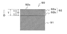
- the gas barrier thin film 92 is provided on one or both of the inner wall surface and the outer wall surface. Further, when the plastic molded body 91 is a film, the gas barrier thin film 92 is provided on one side or both sides.
- the gas barrier thin film 92 contains silicon (Si), carbon (C), and oxygen (O) as constituent elements, and when the X-ray electron spectroscopic analysis is performed under the condition (1), the peak appearance position of the bond energy of Si—C And has a region where the main peak is observed.
- Condition (1) The measurement range is 95 to 105 eV.
- the gas barrier thin film 92 is a thin film having excellent transparency.
- the main peak means a peak having the highest intensity among peaks observed by separating the peaks in the condition (1).
- a peak observed at the peak appearance position of the Si—C bond energy is a Si—Si bond. It is preferably larger than the peak observed at the energy peak appearance position. Thereby, the transparency can be further enhanced.
- the content of Si, O, or C is the content in the breakdown of the three elements of Si, O, and C.
- Si content [%] ⁇ (Si content [atomic%]) / (total content of Si, O and C [atomic%]) ⁇ ⁇ 100
- the content of Si, O, or C is the content in the breakdown of the three elements of Si, O, and C.
- the O content represented by (Equation 3) in the upper layer 92a is lower than the Si content represented by (Equation 2) in the upper layer 92a (Condition 2). It is preferable.
- the upper layer 92a has the highest C content, then the Si content and the O content, and the transparency can be further enhanced.
- (Equation 3) O content [%] ⁇ (O content [atomic%]) / (total content of Si, O and C [atomic%]) ⁇ ⁇ 100
- the content of Si, O, or C is the content in the breakdown of the three elements of Si, O, and C.
- the C content represented by (Equation 1) in the lower layer 92b is higher than the O content represented by (Equation 3) in the lower layer 92b (Condition 3). Is preferred.
- the adhesion between the thin film and the plastic molded body can be increased.
- the gas barrier thin film 92 is preferably substantially colorless and transparent.
- substantially colorless and transparent means that the b * value is 2.0 or less, using the degree of coloration b *, which is the color difference in JIS K 7105-1981 “Testing methods for optical properties of plastics” as an index. Say things.
- the b * value is more preferably 1.7 or less.
- the b * value can be obtained by Equation 4.
- Equation 4 Y or Z is a tristimulus value.
- the correlation between the b * value and visual observation in the present invention is as shown in Table 1.
- the gas barrier plastic molded body 90 preferably has a barrier property improvement rate (Barrier Improvement Factor, hereinafter referred to as BIF) obtained by Equation 5 of 5 or more. More preferably, it is 10 or more.
- BIF Barrier Improvement Factor
- the oxygen permeability is set to 0.1. 0070 cc / container / day or less.
- the oxygen permeability can be 0.0098 cc / container / day or less.
- a method for producing a gas barrier plastic molded body according to this embodiment will be described by taking as an example a case where a gas barrier thin film is formed on the inner surface of a plastic bottle as the plastic molded body 4.
- the present invention is not limited to an apparatus, and for example, as shown in FIG. 2 of Patent Document 1, an apparatus having only one chamber may be used.
- silicon-containing hydrocarbon gas is introduced while the vacuum chamber 31 is evacuated to adjust the pressure in the vacuum chamber 31 to P 0 .
- the pressure in the vacuum chamber 31 increases rapidly, and the pressure in the vacuum chamber 31 may greatly exceed P 0 (for example, exceed P B ) in the initial stage of the preparation process.
- P 0 for example, exceed P B
- the pressure in the vacuum chamber 31 may be adjusted to be less than P 0 in the evacuation process so that the pressure in the vacuum chamber 31 does not become a large pressure exceeding, for example, P B in the preparation process.
- the heating element 42 is heated by energization, for example.
- the heating element 42 has a tantalum carbide phase.
- the tantalum carbide phase is, for example, a carbide obtained by carbonizing tantalum, a tantalum-based alloy, or tantalum or a tantalum-based alloy containing an additive.
- the tantalum carbide phase may contain, for example, Ta 2 C and TaC.
- the tantalum carbide phase may be present throughout the heating element 42 or may be present in a portion of the heating element 42.
- the heating element 42 is heated for the first time in the film forming process, and the heating element 42 is not heated in the exhaust process and the preparation process.
- the only gas remaining in the vacuum chamber 31 is air, and when the heating element 42 is heated in such an atmosphere, the heating element 42 is likely to be oxidized and deteriorated.
- the vacuum breaker valve (not shown) installed in the entrance / exit chamber 32 is operated to open the inside / outside chamber 32 to the atmosphere. At this time, it is preferable that the vacuum chamber 31 is always in a vacuum state, and the heating element 42 disposed in the vacuum chamber 31 is always kept in a vacuum state.
- the open / close gate 56 is opened, the gas barrier plastic molded body is taken out, and a new untreated plastic molded body is introduced. Then, the open / close gate 56 is closed, and the exhaust process, the preparation process, and the film forming process are repeated.
- the method for producing a gas barrier plastic molding having a substantially colorless and transparent gas barrier thin film has been described.
- the gas barrier thin film is not required to have a high degree of transparency (for example, b * exceeds 2 and is 6 or less). The case will be described.
- the method for producing a gas barrier plastic molded body according to the second embodiment includes an evacuation process in which the inside of the vacuum chamber 31 is evacuated to adjust the inside of the vacuum chamber 31 to an initial pressure P 0 or less, and the pressure in the vacuum chamber 31 is P.
- the heating element 42 is adjusted to 0 or less and is not heated, the source gas is introduced into the vacuum chamber 31 to adjust the pressure in the vacuum chamber 31 to P 0 .
- the manufacturing method according to the second embodiment is different from the manufacturing method according to the first embodiment in the following two points.
- the first point is the type of the heating element 42.
- the heating element 42 has a tantalum carbide phase, whereas in the second embodiment, the material of the heating element 42 is not limited.
- the second point is the type of source gas used. While the silicon-containing hydrocarbon gas is used in the first embodiment, the second embodiment is not limited to the silicon-containing hydrocarbon gas.
- the manufacturing method of the second embodiment has the same basic configuration as the manufacturing method according to the first embodiment except for the above two points. For this reason, here, description is omitted about a common structure, and only a different point is demonstrated.
- the material of the heating element is not particularly limited, but C, W, Ta, Nb, Ti, Hf, V, Cr, Mo, Mn, Tc, Re, Fe, Ru, Os, Co, Rh , Ir, Ni, Pd and Pt are preferably included.
- a heat generating body contains the 1 or 2 or more metal element chosen from the group of Ta, W, Mo, and Nb, for example.
- the material containing a metal element is a pure metal, an alloy, a metal or alloy containing an additive, or an intermetallic compound.
- the metal which forms an alloy or an intermetallic compound may be a combination of two or more of the aforementioned metals, or a combination of the aforementioned metals and other metals.
- the other metal is, for example, chromium.
- the alloy or intermetallic compound preferably contains a total of 80 atomic% or more of one or more metal elements selected from the group of Ta, W, Mo and Nb.
- the additive is, for example, an oxide such as zirconia, yttria, calcia, or silica. The addition amount of the additive is preferably 1% by mass or less.
- the source gas other than the above-mentioned silicon-containing hydrocarbon gas is, for example, alkane-based gases such as methane, ethane, propane, butane, pentane, or hexane, and alkene-based gases such as ethylene, propylene, or butyne.
- alkane-based gases such as methane, ethane, propane, butane, pentane, or hexane
- alkene-based gases such as ethylene, propylene, or butyne.
- Example 1 A gas barrier plastic molded body was manufactured using the film forming apparatus shown in FIG.
- a plastic bottle made of PET (with an internal volume of 500 ml) was used as the plastic molding, vinylsilane as the silicon-containing hydrocarbon gas, and tantalum carbide wire ( ⁇ 0.5 mm) as the heating element.
- the plastic bottle was lowered from the entrance / exit chamber, and the heating element and the source gas supply pipe were inserted into the plastic bottle.
- the film forming process was performed as follows. In the film forming process, heating of the heating element is started while continuing the introduction of the silicon-containing hydrocarbon gas, and the heating is performed up to 2100 to 2200 ° C. When the thin film deposited on the inner surface of the plastic bottle reaches 20 nm, the heating is generated. Body heating stopped. Thereafter, the plastic bottle was returned to the entrance / exit chamber, the gate valve was closed, and the gas supply was stopped. In the film forming process, the pressure in the vacuum chamber was allowed to reach P B Pa higher than P A Pa.
- Example 2 A gas barrier plastic molded article was produced in the same manner as in Example 1 except that the pressures P A and P B in each step were adjusted so that (P B ⁇ P A ) / P 0 was 0.15.
- Example 1 A gas barrier plastic molded article was prepared in the same manner as in Example 1 except that a tantalum wire ( ⁇ 0.5 mm) that was not carbonized was used as a heating element, the preparatory process was not performed, and the thickness of the thin film was changed to 36 nm. Manufactured.
- XPS analysis-composition analysis The surface of the thin film of the plastic bottle obtained in Example 1 and Comparative Example 1 in the first series of film forming operations was analyzed using an XPS apparatus (model: QUANTERASXM, manufactured by PHI). Table 2 shows the ratio of constituent elements on the surface of the thin film.
- the conditions of XPS analysis are as follows. Measurement conditions Excitation X-ray: Al mono Detection area: 100 ⁇ m ⁇ Extraction angle: 90deg Detection depth: about 8nm
- FIG. 4 is a narrow scan spectrum of Si2p obtained by XPS analysis of the thin film surface under the condition (1).
- (A) is the thin film of Example 1
- (b) is the thin film of Comparative Example 1.
- a main peak was observed at the peak appearance position of the Si—C bond energy
- Comparative Example 1 the main peak was observed at the peak appearance position of the Si—Si bond energy. A peak was observed.
- Example 1 XPS analysis-depth profile analysis
- Comparative Example 1 the depth profile of the thin film of the plastic bottle obtained in the first series of film forming operations was analyzed for Example 1 and Comparative Example 1 while performing argon ion etching.
- the test piece and analysis conditions were the same as in the composition analysis.
- the gas barrier thin film is divided into two equal parts in the depth direction, in Example 1, 10 nm on the opposite side to the plastic molded body is the upper layer, 10 nm on the plastic molded body side is the lower layer, and in Comparative Example 1, the plastic is 18 nm on the side opposite to the molded body was the upper layer, and 18 nm on the plastic molded body side was the lower layer.
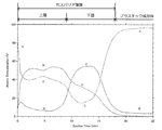
- FIG. 5 is a depth profile of Example 1.
- the O and C profiles have one extreme value in each of the upper layer and the lower layer, the O profile having the highest priority is selected, and Si, C, and O at the extreme values of the O profile are selected.
- the content of was compared.
- the extreme value of the profile of O has a minimum value in Sputter Time 1.5 min included in the upper layer, and has a maximum value in Sputter Time 6.0 min included in the lower layer.
- the C content in Sputter Time 1.5 min was higher than the Si content in Sputter Time 1.5 min.
- the O content in Sputter Time 1.5 min was lower than the Si content in Sputter Time 1.5 min. From the above, in Example 1, it was confirmed that the composition at the extreme value of the O profile of the upper layer had the highest C content, followed by the Si content and the O content.
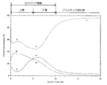
- FIG. 6 is a depth profile of Comparative Example 1.
- the O and C profiles have one extreme value in each of the upper layer and the lower layer, the O profile having the highest priority is selected and Si, C, and O at the extreme values of the O profile are selected. The content of was compared.
- the extreme value of the profile of O has a minimum value in Sputter Time 6.0 min included in the upper layer, and has a maximum value in Sputter Time 13.5 min included in the lower layer.
- the C content in Sputter Time 6.0 min was lower than the Si content in Sputter Time 6.0 min.
- the O content in Sputter Time 6.0 min was lower than the Si content in Sputter Time 6.0 min. From the above, in Comparative Example 1, it was confirmed that the composition at the extreme value of the O profile of the upper layer had the highest Si content.
- Example 1 as shown in FIG. 5, the C content in Sputter Time 6.0 min is higher than the Si content in Sputter Time 6.0 min, and the O content in Sputter Time 6.0 min is Sputter Time 6.0 min. It was higher than the Si content in.
- Comparative Example 1 as shown in FIG. 6, the C content in Sputter Time 13.5 min is lower than the Si content in Sutter Time 13.5 min, and the O content in Sputter Time 13.5 min is Sputter. It was higher than the Si content in Time 13.5 min.
- Example 1 when the integrated value of each atomic concentration of Si, C, and O in the lower layer was determined, in Example 1, the lower layer had the highest C content, and then the O content and the Si content. It could be confirmed. Moreover, in FIG. 6, when the integrated value of each atomic concentration of Si, C, and O in the lower layer was obtained, in Comparative Example 1, the lower layer had the highest O content, followed by the Si content and the C content. I was able to confirm.
- Transparency evaluation The transparency was evaluated using the plastic bottles obtained in the first series of film forming operations for Examples and Comparative Examples. Transparency was evaluated by b * value.
- the b * value was measured using a self-recording spectrophotometer (U-3900, manufactured by Hitachi) equipped with a 60 ⁇ integrating sphere attachment device (for infrared, visible and near infrared) manufactured by the same company.
- a self-recording spectrophotometer U-3900, manufactured by Hitachi
- a 60 ⁇ integrating sphere attachment device for infrared, visible and near infrared manufactured by the same company.
- an ultrasensitive photomultiplier tube R928: for ultraviolet and visible
- cooled PbS for near infrared region
- the transmittance measurement of only the gas barrier thin film can be calculated.
- the b * value in this example is the same as that calculated in the form including the absorption rate of the PET bottle. Show.
- the test piece used for the measurement of glossiness was used for the measurement.
- the average value of 3 sheets is shown in Table 3 as b * value.
- gas barrier property evaluation Regarding Examples and Comparative Examples, gas barrier properties were evaluated using each plastic bottle obtained when the number of repetitions of a series of film forming operations was 1st, 100th, and 200th. The gas barrier property was evaluated by BIF. First, oxygen permeability was measured for each plastic bottle of the example or comparative example. The oxygen permeability was measured under the conditions of 23 ° C. and 90% RH using an oxygen permeability measuring device (model: Oxtran 2/20, manufactured by Modern Control), conditioned for 24 hours from the start of measurement, and then started measurement. The value after 72 hours had passed.
- an oxygen permeability measuring device model: Oxtran 2/20, manufactured by Modern Control
- the oxygen permeability value of the unformed film bottle is defined as the oxygen permeability value of the plastic molded body where the thin film is not formed, and the oxygen permeability value of each plastic bottle of the example or comparative example is used as the gas barrier plastic molding. Calculated as oxygen permeability of the body.
- the evaluation criteria are as follows. The evaluation results are shown in Table 3. A: BIF of each plastic bottle is 10 or more (practical level). ⁇ : BIF of each plastic bottle is 5 or more and less than 10 (practical lower limit level). X: BIF of each plastic bottle is less than 5 (practical unsuitable level).
- each Example was substantially colorless and transparent and had high gas barrier properties. Moreover, compared with the comparative example 1, it has confirmed that it was a manufacturing method excellent in durability with respect to the catalyst activity and intensity
- Example 1 and Example 2 were able to form a thin film having a high gas barrier property without losing the catalytic activity of the heating element even when the heating element was repeatedly used 10,000 times or more.
- (P B -P A ) / P 0 was 0.11 or more, and a gas barrier thin film having high transparency and high gas barrier properties could be formed.
- (P B -P A ) / P 0 was 0.15 or more, and the gas barrier property was kept high even when the heating element was repeatedly used.
Landscapes
- Chemical & Material Sciences (AREA)
- Engineering & Computer Science (AREA)
- Mechanical Engineering (AREA)
- General Chemical & Material Sciences (AREA)
- Chemical Kinetics & Catalysis (AREA)
- Materials Engineering (AREA)
- Metallurgy (AREA)
- Organic Chemistry (AREA)
- Inorganic Chemistry (AREA)
- Laminated Bodies (AREA)
- Chemical Vapour Deposition (AREA)
- Details Of Rigid Or Semi-Rigid Containers (AREA)
Abstract
Priority Applications (8)
| Application Number | Priority Date | Filing Date | Title |
|---|---|---|---|
| AU2016248605A AU2016248605A1 (en) | 2015-04-17 | 2016-04-05 | Gas-barrier plastic molded product and method for manufacturing same |
| SG11201708290QA SG11201708290QA (en) | 2015-04-17 | 2016-04-05 | Gas-barrier plastic molded product and method for manufacturing same |
| US15/566,515 US10487397B2 (en) | 2015-04-17 | 2016-04-05 | Gas-barrier plastic molded product and method for manufacturing same |
| KR1020177032902A KR20170138476A (ko) | 2015-04-17 | 2016-04-05 | 가스 배리어성 플라스틱 성형체 및 그 제조 방법 |
| MYPI2017703465A MY186446A (en) | 2015-04-17 | 2016-04-05 | Gas-barrier plastic molded product and method for manufacturing same |
| EP16779943.6A EP3284846B1 (fr) | 2015-04-17 | 2016-04-05 | Produit moulé en plastique faisant barrière contre les gaz et son procédé de fabrication |
| CN201680021428.1A CN107429392B (zh) | 2015-04-17 | 2016-04-05 | 阻气性塑料成型体及其制造方法 |
| PH12017501752A PH12017501752A1 (en) | 2015-04-17 | 2017-09-25 | Gas-barrier plastic molded product and method for manufacturing same |
Applications Claiming Priority (2)
| Application Number | Priority Date | Filing Date | Title |
|---|---|---|---|
| JP2015-085018 | 2015-04-17 | ||
| JP2015085018A JP6474673B2 (ja) | 2015-04-17 | 2015-04-17 | ガスバリア性プラスチック成形体及びその製造方法 |
Publications (1)
| Publication Number | Publication Date |
|---|---|
| WO2016167152A1 true WO2016167152A1 (fr) | 2016-10-20 |
Family
ID=57126273
Family Applications (1)
| Application Number | Title | Priority Date | Filing Date |
|---|---|---|---|
| PCT/JP2016/061070 WO2016167152A1 (fr) | 2015-04-17 | 2016-04-05 | Produit moulé en plastique faisant barrière contre les gaz et son procédé de fabrication |
Country Status (11)
| Country | Link |
|---|---|
| US (1) | US10487397B2 (fr) |
| EP (1) | EP3284846B1 (fr) |
| JP (1) | JP6474673B2 (fr) |
| KR (1) | KR20170138476A (fr) |
| CN (1) | CN107429392B (fr) |
| AU (1) | AU2016248605A1 (fr) |
| MY (1) | MY186446A (fr) |
| PH (1) | PH12017501752A1 (fr) |
| SG (1) | SG11201708290QA (fr) |
| TW (1) | TWI686497B (fr) |
| WO (1) | WO2016167152A1 (fr) |
Cited By (2)
| Publication number | Priority date | Publication date | Assignee | Title |
|---|---|---|---|---|
| JP2018095937A (ja) * | 2016-12-15 | 2018-06-21 | 三菱重工機械システム株式会社 | 電極状態評価装置、成膜装置及び電極状態評価方法 |
| JP2019155704A (ja) * | 2018-03-13 | 2019-09-19 | 東レエンジニアリング株式会社 | バリアフィルムおよび光変換部材 |
Families Citing this family (1)
| Publication number | Priority date | Publication date | Assignee | Title |
|---|---|---|---|---|
| CN107429394A (zh) * | 2015-02-18 | 2017-12-01 | 麒麟株式会社 | 发热体及其制造方法 |
Citations (5)
| Publication number | Priority date | Publication date | Assignee | Title |
|---|---|---|---|---|
| JP2004107689A (ja) * | 2002-09-13 | 2004-04-08 | Ulvac Japan Ltd | ダイヤモンド状炭素膜形成方法及び製造装置 |
| WO2006126677A1 (fr) * | 2005-05-27 | 2006-11-30 | Kirin Beer Kabushiki Kaisha | Appareil de fabrication de conteneur plastique de protection contre le gaz, procédé de fabrication de conteneur et conteneur |
| JP2009120885A (ja) * | 2007-11-13 | 2009-06-04 | Toyo Advanced Technologies Co Ltd | 炭素質薄膜及びその製造方法 |
| WO2012091097A1 (fr) * | 2010-12-28 | 2012-07-05 | 麒麟麦酒株式会社 | Produit moulé en matière plastique à barrière contre les gaz et son procédé de fabrication |
| WO2012091095A1 (fr) * | 2010-12-28 | 2012-07-05 | 麒麟麦酒株式会社 | Procédé de production d'un corps moulé en plastique de barrière contre les gaz |
Family Cites Families (8)
| Publication number | Priority date | Publication date | Assignee | Title |
|---|---|---|---|---|
| EP1317775A4 (fr) * | 2000-03-20 | 2009-01-28 | Bekaert Sa Nv | Materiels comportant des constantes dielectriques faibles et procede de production |
| US7288311B2 (en) * | 2003-02-10 | 2007-10-30 | Dai Nippon Printing Co., Ltd. | Barrier film |
| CN102245379B (zh) * | 2008-12-12 | 2015-06-24 | 琳得科株式会社 | 叠层体、其制造方法、电子设备构件和电子设备 |
| KR101489551B1 (ko) * | 2009-05-22 | 2015-02-03 | 린텍 가부시키가이샤 | 성형체, 그 제조 방법, 전자 디바이스용 부재 및 전자 디바이스 |
| JP5706777B2 (ja) | 2011-07-25 | 2015-04-22 | 麒麟麦酒株式会社 | ガスバリア性プラスチック成形体 |
| AU2012361615B2 (en) | 2011-12-27 | 2015-08-06 | Kirin Beer Kabushiki Kaisha | Apparatus for forming thin film |
| TWI576242B (zh) | 2011-12-28 | 2017-04-01 | Kirin Brewery | Gas barrier plastic molded body and manufacturing method thereof |
| JP6009243B2 (ja) | 2012-06-27 | 2016-10-19 | 麒麟麦酒株式会社 | 炭酸飲料用ボトル及びその製造方法 |
-
2015
- 2015-04-17 JP JP2015085018A patent/JP6474673B2/ja active Active
-
2016
- 2016-04-05 SG SG11201708290QA patent/SG11201708290QA/en unknown
- 2016-04-05 MY MYPI2017703465A patent/MY186446A/en unknown
- 2016-04-05 EP EP16779943.6A patent/EP3284846B1/fr active Active
- 2016-04-05 AU AU2016248605A patent/AU2016248605A1/en not_active Abandoned
- 2016-04-05 US US15/566,515 patent/US10487397B2/en active Active
- 2016-04-05 WO PCT/JP2016/061070 patent/WO2016167152A1/fr active Application Filing
- 2016-04-05 CN CN201680021428.1A patent/CN107429392B/zh active Active
- 2016-04-05 KR KR1020177032902A patent/KR20170138476A/ko unknown
- 2016-04-11 TW TW105111263A patent/TWI686497B/zh not_active IP Right Cessation
-
2017
- 2017-09-25 PH PH12017501752A patent/PH12017501752A1/en unknown
Patent Citations (5)
| Publication number | Priority date | Publication date | Assignee | Title |
|---|---|---|---|---|
| JP2004107689A (ja) * | 2002-09-13 | 2004-04-08 | Ulvac Japan Ltd | ダイヤモンド状炭素膜形成方法及び製造装置 |
| WO2006126677A1 (fr) * | 2005-05-27 | 2006-11-30 | Kirin Beer Kabushiki Kaisha | Appareil de fabrication de conteneur plastique de protection contre le gaz, procédé de fabrication de conteneur et conteneur |
| JP2009120885A (ja) * | 2007-11-13 | 2009-06-04 | Toyo Advanced Technologies Co Ltd | 炭素質薄膜及びその製造方法 |
| WO2012091097A1 (fr) * | 2010-12-28 | 2012-07-05 | 麒麟麦酒株式会社 | Produit moulé en matière plastique à barrière contre les gaz et son procédé de fabrication |
| WO2012091095A1 (fr) * | 2010-12-28 | 2012-07-05 | 麒麟麦酒株式会社 | Procédé de production d'un corps moulé en plastique de barrière contre les gaz |
Non-Patent Citations (1)
| Title |
|---|
| See also references of EP3284846A4 * |
Cited By (4)
| Publication number | Priority date | Publication date | Assignee | Title |
|---|---|---|---|---|
| JP2018095937A (ja) * | 2016-12-15 | 2018-06-21 | 三菱重工機械システム株式会社 | 電極状態評価装置、成膜装置及び電極状態評価方法 |
| JP2019155704A (ja) * | 2018-03-13 | 2019-09-19 | 東レエンジニアリング株式会社 | バリアフィルムおよび光変換部材 |
| WO2019176936A1 (fr) * | 2018-03-13 | 2019-09-19 | 東レエンジニアリング株式会社 | Film barrière et élément de conversion de lumière |
| JP7163041B2 (ja) | 2018-03-13 | 2022-10-31 | 東レエンジニアリング株式会社 | バリアフィルムおよび光変換部材 |
Also Published As
| Publication number | Publication date |
|---|---|
| EP3284846A4 (fr) | 2018-12-19 |
| JP2016204685A (ja) | 2016-12-08 |
| MY186446A (en) | 2021-07-22 |
| US10487397B2 (en) | 2019-11-26 |
| CN107429392B (zh) | 2019-08-20 |
| PH12017501752A1 (en) | 2018-04-11 |
| US20180127872A1 (en) | 2018-05-10 |
| KR20170138476A (ko) | 2017-12-15 |
| AU2016248605A1 (en) | 2017-10-19 |
| TWI686497B (zh) | 2020-03-01 |
| TW201641732A (zh) | 2016-12-01 |
| SG11201708290QA (en) | 2017-11-29 |
| EP3284846B1 (fr) | 2021-02-17 |
| JP6474673B2 (ja) | 2019-02-27 |
| CN107429392A (zh) | 2017-12-01 |
| EP3284846A1 (fr) | 2018-02-21 |
Similar Documents
| Publication | Publication Date | Title |
|---|---|---|
| AU2011350429B2 (en) | Gas-barrier plastic molded product and manufacturing process therefor | |
| JP5695673B2 (ja) | ガスバリア性プラスチック成形体の製造方法 | |
| WO2016167152A1 (fr) | Produit moulé en plastique faisant barrière contre les gaz et son procédé de fabrication | |
| JP2007261077A (ja) | Dlc膜コーティング生分解性プラスチック容器又はフィルム及びその製造方法 | |
| JP5706777B2 (ja) | ガスバリア性プラスチック成形体 | |
| JP6009243B2 (ja) | 炭酸飲料用ボトル及びその製造方法 | |
| JP5566334B2 (ja) | ガスバリア性プラスチック成形体及びその製造方法 | |
| EP3093309B1 (fr) | Procédé de dépôt d'un revêtement de barrière aux gaz sur un film polymère ou récipient en polymère et film polymère ou récipient en polymère revêtu d'une telle barrière aux gaz | |
| JP2017081615A (ja) | 合成樹脂製容器 | |
| JP5779044B2 (ja) | 濡れ性の制御方法 | |
| JP2007168882A (ja) | ガスバリア性プラスチック容器 | |
| JP7005256B2 (ja) | ガスバリア性容器 | |
| TWI537415B (zh) | Production method of gas barrier plastic molded body |
Legal Events
| Date | Code | Title | Description |
|---|---|---|---|
| 121 | Ep: the epo has been informed by wipo that ep was designated in this application |
Ref document number: 16779943 Country of ref document: EP Kind code of ref document: A1 |
|
| WWE | Wipo information: entry into national phase |
Ref document number: 12017501752 Country of ref document: PH |
|
| WWE | Wipo information: entry into national phase |
Ref document number: 11201708290Q Country of ref document: SG |
|
| WWE | Wipo information: entry into national phase |
Ref document number: 15566515 Country of ref document: US |
|
| NENP | Non-entry into the national phase |
Ref country code: DE |
|
| ENP | Entry into the national phase |
Ref document number: 2016248605 Country of ref document: AU Date of ref document: 20160405 Kind code of ref document: A |
|
| REEP | Request for entry into the european phase |
Ref document number: 2016779943 Country of ref document: EP |
|
| ENP | Entry into the national phase |
Ref document number: 20177032902 Country of ref document: KR Kind code of ref document: A |