EP3284846B1 - Produit moulé en plastique faisant barrière contre les gaz et son procédé de fabrication - Google Patents
Produit moulé en plastique faisant barrière contre les gaz et son procédé de fabrication Download PDFInfo
- Publication number
- EP3284846B1 EP3284846B1 EP16779943.6A EP16779943A EP3284846B1 EP 3284846 B1 EP3284846 B1 EP 3284846B1 EP 16779943 A EP16779943 A EP 16779943A EP 3284846 B1 EP3284846 B1 EP 3284846B1
- Authority
- EP
- European Patent Office
- Prior art keywords
- gas barrier
- molded body
- plastic molded
- content
- vacuum chamber
- Prior art date
- Legal status (The legal status is an assumption and is not a legal conclusion. Google has not performed a legal analysis and makes no representation as to the accuracy of the status listed.)
- Active
Links
- 229920003023 plastic Polymers 0.000 title claims description 135
- 239000004033 plastic Substances 0.000 title claims description 135
- 238000004519 manufacturing process Methods 0.000 title claims description 26
- 238000000034 method Methods 0.000 title claims description 8
- 239000007789 gas Substances 0.000 claims description 178
- 230000004888 barrier function Effects 0.000 claims description 124
- 239000010409 thin film Substances 0.000 claims description 82
- 230000020169 heat generation Effects 0.000 claims description 64
- 239000010408 film Substances 0.000 claims description 57
- 229910052710 silicon Inorganic materials 0.000 claims description 51
- XUIMIQQOPSSXEZ-UHFFFAOYSA-N Silicon Chemical compound [Si] XUIMIQQOPSSXEZ-UHFFFAOYSA-N 0.000 claims description 25
- 239000010703 silicon Substances 0.000 claims description 25
- 229910052799 carbon Inorganic materials 0.000 claims description 24
- 229930195733 hydrocarbon Natural products 0.000 claims description 20
- 150000002430 hydrocarbons Chemical class 0.000 claims description 20
- 239000004215 Carbon black (E152) Substances 0.000 claims description 19
- 239000000203 mixture Substances 0.000 claims description 18
- QVGXLLKOCUKJST-UHFFFAOYSA-N atomic oxygen Chemical compound [O] QVGXLLKOCUKJST-UHFFFAOYSA-N 0.000 claims description 17
- 229910003468 tantalcarbide Inorganic materials 0.000 claims description 13
- NFFIWVVINABMKP-UHFFFAOYSA-N methylidynetantalum Chemical compound [Ta]#C NFFIWVVINABMKP-UHFFFAOYSA-N 0.000 claims description 12
- 238000005259 measurement Methods 0.000 claims description 11
- 238000010438 heat treatment Methods 0.000 claims description 10
- 229910018540 Si C Inorganic materials 0.000 claims description 8
- 229910010271 silicon carbide Inorganic materials 0.000 claims description 8
- 239000000470 constituent Substances 0.000 claims description 7
- OKTJSMMVPCPJKN-UHFFFAOYSA-N Carbon Chemical compound [C] OKTJSMMVPCPJKN-UHFFFAOYSA-N 0.000 claims description 5
- 238000004611 spectroscopical analysis Methods 0.000 claims description 5
- 239000010410 layer Substances 0.000 description 73
- 229910052760 oxygen Inorganic materials 0.000 description 43
- 230000000052 comparative effect Effects 0.000 description 23
- 229920005989 resin Polymers 0.000 description 20
- 239000011347 resin Substances 0.000 description 20
- 238000000605 extraction Methods 0.000 description 18
- 238000003780 insertion Methods 0.000 description 17
- 230000037431 insertion Effects 0.000 description 17
- 239000001301 oxygen Substances 0.000 description 16
- 229910052751 metal Inorganic materials 0.000 description 12
- 230000035699 permeability Effects 0.000 description 12
- 239000002994 raw material Substances 0.000 description 12
- 238000004458 analytical method Methods 0.000 description 11
- 230000015572 biosynthetic process Effects 0.000 description 10
- 239000002184 metal Substances 0.000 description 10
- 229910052715 tantalum Inorganic materials 0.000 description 9
- -1 polyethylene terephthalate Polymers 0.000 description 8
- 229920000139 polyethylene terephthalate Polymers 0.000 description 8
- 239000005020 polyethylene terephthalate Substances 0.000 description 8
- 238000011156 evaluation Methods 0.000 description 7
- 239000000463 material Substances 0.000 description 7
- GUVRBAGPIYLISA-UHFFFAOYSA-N tantalum atom Chemical compound [Ta] GUVRBAGPIYLISA-UHFFFAOYSA-N 0.000 description 7
- 229910045601 alloy Inorganic materials 0.000 description 6
- 239000000956 alloy Substances 0.000 description 6
- 238000012360 testing method Methods 0.000 description 5
- XKRFYHLGVUSROY-UHFFFAOYSA-N Argon Chemical compound [Ar] XKRFYHLGVUSROY-UHFFFAOYSA-N 0.000 description 4
- IJGRMHOSHXDMSA-UHFFFAOYSA-N Atomic nitrogen Chemical compound N#N IJGRMHOSHXDMSA-UHFFFAOYSA-N 0.000 description 4
- 239000000654 additive Substances 0.000 description 4
- 230000000996 additive effect Effects 0.000 description 4
- 230000015556 catabolic process Effects 0.000 description 4
- 230000008859 change Effects 0.000 description 4
- 238000006243 chemical reaction Methods 0.000 description 4
- 238000006731 degradation reaction Methods 0.000 description 4
- 230000003647 oxidation Effects 0.000 description 4
- 238000007254 oxidation reaction Methods 0.000 description 4
- ZWEHNKRNPOVVGH-UHFFFAOYSA-N 2-Butanone Chemical compound CCC(C)=O ZWEHNKRNPOVVGH-UHFFFAOYSA-N 0.000 description 3
- UHOVQNZJYSORNB-UHFFFAOYSA-N Benzene Chemical compound C1=CC=CC=C1 UHOVQNZJYSORNB-UHFFFAOYSA-N 0.000 description 3
- LFQSCWFLJHTTHZ-UHFFFAOYSA-N Ethanol Chemical compound CCO LFQSCWFLJHTTHZ-UHFFFAOYSA-N 0.000 description 3
- WSFSSNUMVMOOMR-UHFFFAOYSA-N Formaldehyde Chemical compound O=C WSFSSNUMVMOOMR-UHFFFAOYSA-N 0.000 description 3
- OKKJLVBELUTLKV-UHFFFAOYSA-N Methanol Chemical compound OC OKKJLVBELUTLKV-UHFFFAOYSA-N 0.000 description 3
- 229910008045 Si-Si Inorganic materials 0.000 description 3
- 229910006411 Si—Si Inorganic materials 0.000 description 3
- YXFVVABEGXRONW-UHFFFAOYSA-N Toluene Chemical compound CC1=CC=CC=C1 YXFVVABEGXRONW-UHFFFAOYSA-N 0.000 description 3
- 235000013361 beverage Nutrition 0.000 description 3
- 230000003197 catalytic effect Effects 0.000 description 3
- 238000005229 chemical vapour deposition Methods 0.000 description 3
- 238000010586 diagram Methods 0.000 description 3
- 229910000765 intermetallic Inorganic materials 0.000 description 3
- 229910052750 molybdenum Inorganic materials 0.000 description 3
- VLKZOEOYAKHREP-UHFFFAOYSA-N n-Hexane Chemical compound CCCCCC VLKZOEOYAKHREP-UHFFFAOYSA-N 0.000 description 3
- OFBQJSOFQDEBGM-UHFFFAOYSA-N n-pentane Natural products CCCCC OFBQJSOFQDEBGM-UHFFFAOYSA-N 0.000 description 3
- 229910052758 niobium Inorganic materials 0.000 description 3
- 238000002834 transmittance Methods 0.000 description 3
- 229910052721 tungsten Inorganic materials 0.000 description 3
- UKRDPEFKFJNXQM-UHFFFAOYSA-N vinylsilane Chemical compound [SiH3]C=C UKRDPEFKFJNXQM-UHFFFAOYSA-N 0.000 description 3
- YBYIRNPNPLQARY-UHFFFAOYSA-N 1H-indene Chemical compound C1=CC=C2CC=CC2=C1 YBYIRNPNPLQARY-UHFFFAOYSA-N 0.000 description 2
- IKHGUXGNUITLKF-UHFFFAOYSA-N Acetaldehyde Chemical compound CC=O IKHGUXGNUITLKF-UHFFFAOYSA-N 0.000 description 2
- CSCPPACGZOOCGX-UHFFFAOYSA-N Acetone Chemical compound CC(C)=O CSCPPACGZOOCGX-UHFFFAOYSA-N 0.000 description 2
- KAKZBPTYRLMSJV-UHFFFAOYSA-N Butadiene Chemical compound C=CC=C KAKZBPTYRLMSJV-UHFFFAOYSA-N 0.000 description 2
- 229920000089 Cyclic olefin copolymer Polymers 0.000 description 2
- 239000004713 Cyclic olefin copolymer Substances 0.000 description 2
- UFWIBTONFRDIAS-UHFFFAOYSA-N Naphthalene Chemical compound C1=CC=CC2=CC=CC=C21 UFWIBTONFRDIAS-UHFFFAOYSA-N 0.000 description 2
- 239000004743 Polypropylene Substances 0.000 description 2
- ATUOYWHBWRKTHZ-UHFFFAOYSA-N Propane Chemical compound CCC ATUOYWHBWRKTHZ-UHFFFAOYSA-N 0.000 description 2
- VYPSYNLAJGMNEJ-UHFFFAOYSA-N Silicium dioxide Chemical compound O=[Si]=O VYPSYNLAJGMNEJ-UHFFFAOYSA-N 0.000 description 2
- BOTDANWDWHJENH-UHFFFAOYSA-N Tetraethyl orthosilicate Chemical compound CCO[Si](OCC)(OCC)OCC BOTDANWDWHJENH-UHFFFAOYSA-N 0.000 description 2
- MCMNRKCIXSYSNV-UHFFFAOYSA-N Zirconium dioxide Chemical compound O=[Zr]=O MCMNRKCIXSYSNV-UHFFFAOYSA-N 0.000 description 2
- 229910052786 argon Inorganic materials 0.000 description 2
- KDKYADYSIPSCCQ-UHFFFAOYSA-N but-1-yne Chemical compound CCC#C KDKYADYSIPSCCQ-UHFFFAOYSA-N 0.000 description 2
- 229910052804 chromium Inorganic materials 0.000 description 2
- 239000011651 chromium Substances 0.000 description 2
- 150000001875 compounds Chemical class 0.000 description 2
- 150000001925 cycloalkenes Chemical class 0.000 description 2
- HGCIXCUEYOPUTN-UHFFFAOYSA-N cyclohexene Chemical compound C1CCC=CC1 HGCIXCUEYOPUTN-UHFFFAOYSA-N 0.000 description 2
- LPIQUOYDBNQMRZ-UHFFFAOYSA-N cyclopentene Chemical compound C1CC=CC1 LPIQUOYDBNQMRZ-UHFFFAOYSA-N 0.000 description 2
- 238000001514 detection method Methods 0.000 description 2
- UBHZUDXTHNMNLD-UHFFFAOYSA-N dimethylsilane Chemical compound C[SiH2]C UBHZUDXTHNMNLD-UHFFFAOYSA-N 0.000 description 2
- 230000000694 effects Effects 0.000 description 2
- 238000004050 hot filament vapor deposition Methods 0.000 description 2
- 230000006872 improvement Effects 0.000 description 2
- 230000000977 initiatory effect Effects 0.000 description 2
- 150000002739 metals Chemical class 0.000 description 2
- VNWKTOKETHGBQD-UHFFFAOYSA-N methane Chemical compound C VNWKTOKETHGBQD-UHFFFAOYSA-N 0.000 description 2
- 229910052757 nitrogen Inorganic materials 0.000 description 2
- YNPNZTXNASCQKK-UHFFFAOYSA-N phenanthrene Chemical compound C1=CC=C2C3=CC=CC=C3C=CC2=C1 YNPNZTXNASCQKK-UHFFFAOYSA-N 0.000 description 2
- 229910000077 silane Inorganic materials 0.000 description 2
- 239000002356 single layer Substances 0.000 description 2
- 238000001228 spectrum Methods 0.000 description 2
- 238000000992 sputter etching Methods 0.000 description 2
- CPUDPFPXCZDNGI-UHFFFAOYSA-N triethoxy(methyl)silane Chemical compound CCO[Si](C)(OCC)OCC CPUDPFPXCZDNGI-UHFFFAOYSA-N 0.000 description 2
- PQDJYEQOELDLCP-UHFFFAOYSA-N trimethylsilane Chemical compound C[SiH](C)C PQDJYEQOELDLCP-UHFFFAOYSA-N 0.000 description 2
- 229940094989 trimethylsilane Drugs 0.000 description 2
- 238000011179 visual inspection Methods 0.000 description 2
- PMJHHCWVYXUKFD-SNAWJCMRSA-N (E)-1,3-pentadiene Chemical compound C\C=C\C=C PMJHHCWVYXUKFD-SNAWJCMRSA-N 0.000 description 1
- KWEKXPWNFQBJAY-UHFFFAOYSA-N (dimethyl-$l^{3}-silanyl)oxy-dimethylsilicon Chemical compound C[Si](C)O[Si](C)C KWEKXPWNFQBJAY-UHFFFAOYSA-N 0.000 description 1
- VXEGSRKPIUDPQT-UHFFFAOYSA-N 4-[4-(4-methoxyphenyl)piperazin-1-yl]aniline Chemical compound C1=CC(OC)=CC=C1N1CCN(C=2C=CC(N)=CC=2)CC1 VXEGSRKPIUDPQT-UHFFFAOYSA-N 0.000 description 1
- WSSSPWUEQFSQQG-UHFFFAOYSA-N 4-methyl-1-pentene Chemical compound CC(C)CC=C WSSSPWUEQFSQQG-UHFFFAOYSA-N 0.000 description 1
- NLHHRLWOUZZQLW-UHFFFAOYSA-N Acrylonitrile Chemical compound C=CC#N NLHHRLWOUZZQLW-UHFFFAOYSA-N 0.000 description 1
- ODINCKMPIJJUCX-UHFFFAOYSA-N Calcium oxide Chemical compound [Ca]=O ODINCKMPIJJUCX-UHFFFAOYSA-N 0.000 description 1
- VYZAMTAEIAYCRO-UHFFFAOYSA-N Chromium Chemical compound [Cr] VYZAMTAEIAYCRO-UHFFFAOYSA-N 0.000 description 1
- XDTMQSROBMDMFD-UHFFFAOYSA-N Cyclohexane Chemical compound C1CCCCC1 XDTMQSROBMDMFD-UHFFFAOYSA-N 0.000 description 1
- LVZWSLJZHVFIQJ-UHFFFAOYSA-N Cyclopropane Chemical compound C1CC1 LVZWSLJZHVFIQJ-UHFFFAOYSA-N 0.000 description 1
- OTMSDBZUPAUEDD-UHFFFAOYSA-N Ethane Chemical compound CC OTMSDBZUPAUEDD-UHFFFAOYSA-N 0.000 description 1
- 229920000219 Ethylene vinyl alcohol Polymers 0.000 description 1
- UFHFLCQGNIYNRP-UHFFFAOYSA-N Hydrogen Chemical compound [H][H] UFHFLCQGNIYNRP-UHFFFAOYSA-N 0.000 description 1
- CTQNGGLPUBDAKN-UHFFFAOYSA-N O-Xylene Chemical compound CC1=CC=CC=C1C CTQNGGLPUBDAKN-UHFFFAOYSA-N 0.000 description 1
- 229930182556 Polyacetal Natural products 0.000 description 1
- 239000004962 Polyamide-imide Substances 0.000 description 1
- 229920001328 Polyvinylidene chloride Polymers 0.000 description 1
- 229910018557 Si O Inorganic materials 0.000 description 1
- 229910004448 Ta2C Inorganic materials 0.000 description 1
- XECAHXYUAAWDEL-UHFFFAOYSA-N acrylonitrile butadiene styrene Chemical compound C=CC=C.C=CC#N.C=CC1=CC=CC=C1 XECAHXYUAAWDEL-UHFFFAOYSA-N 0.000 description 1
- 239000004676 acrylonitrile butadiene styrene Substances 0.000 description 1
- 229920000122 acrylonitrile butadiene styrene Polymers 0.000 description 1
- 229920001893 acrylonitrile styrene Polymers 0.000 description 1
- 150000001299 aldehydes Chemical class 0.000 description 1
- 150000001335 aliphatic alkanes Chemical class 0.000 description 1
- 150000001336 alkenes Chemical class 0.000 description 1
- 150000001345 alkine derivatives Chemical class 0.000 description 1
- HSFWRNGVRCDJHI-UHFFFAOYSA-N alpha-acetylene Natural products C#C HSFWRNGVRCDJHI-UHFFFAOYSA-N 0.000 description 1
- 150000004945 aromatic hydrocarbons Chemical class 0.000 description 1
- 239000001273 butane Substances 0.000 description 1
- 239000000292 calcium oxide Substances 0.000 description 1
- 235000012255 calcium oxide Nutrition 0.000 description 1
- 235000014171 carbonated beverage Nutrition 0.000 description 1
- 238000003763 carbonization Methods 0.000 description 1
- 239000013626 chemical specie Substances 0.000 description 1
- 229920006026 co-polymeric resin Polymers 0.000 description 1
- 239000011248 coating agent Substances 0.000 description 1
- 238000000576 coating method Methods 0.000 description 1
- 230000003750 conditioning effect Effects 0.000 description 1
- 238000001816 cooling Methods 0.000 description 1
- 150000001924 cycloalkanes Chemical class 0.000 description 1
- 238000000151 deposition Methods 0.000 description 1
- 150000001993 dienes Chemical class 0.000 description 1
- UCXUKTLCVSGCNR-UHFFFAOYSA-N diethylsilane Chemical compound CC[SiH2]CC UCXUKTLCVSGCNR-UHFFFAOYSA-N 0.000 description 1
- 230000005611 electricity Effects 0.000 description 1
- 238000005516 engineering process Methods 0.000 description 1
- FWDBOZPQNFPOLF-UHFFFAOYSA-N ethenyl(triethoxy)silane Chemical compound CCO[Si](OCC)(OCC)C=C FWDBOZPQNFPOLF-UHFFFAOYSA-N 0.000 description 1
- NKSJNEHGWDZZQF-UHFFFAOYSA-N ethenyl(trimethoxy)silane Chemical compound CO[Si](OC)(OC)C=C NKSJNEHGWDZZQF-UHFFFAOYSA-N 0.000 description 1
- GCSJLQSCSDMKTP-UHFFFAOYSA-N ethenyl(trimethyl)silane Chemical compound C[Si](C)(C)C=C GCSJLQSCSDMKTP-UHFFFAOYSA-N 0.000 description 1
- 125000002534 ethynyl group Chemical group [H]C#C* 0.000 description 1
- 235000013305 food Nutrition 0.000 description 1
- 235000015203 fruit juice Nutrition 0.000 description 1
- 229910052735 hafnium Inorganic materials 0.000 description 1
- NEXSMEBSBIABKL-UHFFFAOYSA-N hexamethyldisilane Chemical compound C[Si](C)(C)[Si](C)(C)C NEXSMEBSBIABKL-UHFFFAOYSA-N 0.000 description 1
- FFUAGWLWBBFQJT-UHFFFAOYSA-N hexamethyldisilazane Chemical compound C[Si](C)(C)N[Si](C)(C)C FFUAGWLWBBFQJT-UHFFFAOYSA-N 0.000 description 1
- UQEAIHBTYFGYIE-UHFFFAOYSA-N hexamethyldisiloxane Chemical compound C[Si](C)(C)O[Si](C)(C)C UQEAIHBTYFGYIE-UHFFFAOYSA-N 0.000 description 1
- 239000001257 hydrogen Substances 0.000 description 1
- 229910052739 hydrogen Inorganic materials 0.000 description 1
- 229920000554 ionomer Polymers 0.000 description 1
- 229910052741 iridium Inorganic materials 0.000 description 1
- 229910052742 iron Inorganic materials 0.000 description 1
- 150000002576 ketones Chemical class 0.000 description 1
- 239000007788 liquid Substances 0.000 description 1
- 229910052748 manganese Inorganic materials 0.000 description 1
- UIUXUFNYAYAMOE-UHFFFAOYSA-N methylsilane Chemical compound [SiH3]C UIUXUFNYAYAMOE-UHFFFAOYSA-N 0.000 description 1
- BFXIKLCIZHOAAZ-UHFFFAOYSA-N methyltrimethoxysilane Chemical compound CO[Si](C)(OC)OC BFXIKLCIZHOAAZ-UHFFFAOYSA-N 0.000 description 1
- 238000012986 modification Methods 0.000 description 1
- 230000004048 modification Effects 0.000 description 1
- IJDNQMDRQITEOD-UHFFFAOYSA-N n-butane Chemical compound CCCC IJDNQMDRQITEOD-UHFFFAOYSA-N 0.000 description 1
- 229910052759 nickel Inorganic materials 0.000 description 1
- HMMGMWAXVFQUOA-UHFFFAOYSA-N octamethylcyclotetrasiloxane Chemical compound C[Si]1(C)O[Si](C)(C)O[Si](C)(C)O[Si](C)(C)O1 HMMGMWAXVFQUOA-UHFFFAOYSA-N 0.000 description 1
- 230000003287 optical effect Effects 0.000 description 1
- 229910052762 osmium Inorganic materials 0.000 description 1
- 238000004806 packaging method and process Methods 0.000 description 1
- 229910052763 palladium Inorganic materials 0.000 description 1
- 238000005192 partition Methods 0.000 description 1
- RGSFGYAAUTVSQA-UHFFFAOYSA-N pentamethylene Natural products C1CCCC1 RGSFGYAAUTVSQA-UHFFFAOYSA-N 0.000 description 1
- PARWUHTVGZSQPD-UHFFFAOYSA-N phenylsilane Chemical compound [SiH3]C1=CC=CC=C1 PARWUHTVGZSQPD-UHFFFAOYSA-N 0.000 description 1
- 229910052697 platinum Inorganic materials 0.000 description 1
- 229920003207 poly(ethylene-2,6-naphthalate) Polymers 0.000 description 1
- 229920003229 poly(methyl methacrylate) Polymers 0.000 description 1
- 229920002492 poly(sulfone) Polymers 0.000 description 1
- 229920006122 polyamide resin Polymers 0.000 description 1
- 229920002312 polyamide-imide Polymers 0.000 description 1
- 229920001707 polybutylene terephthalate Polymers 0.000 description 1
- 229920005668 polycarbonate resin Polymers 0.000 description 1
- 239000004431 polycarbonate resin Substances 0.000 description 1
- 239000011112 polyethylene naphthalate Substances 0.000 description 1
- 229920013716 polyethylene resin Polymers 0.000 description 1
- 239000004926 polymethyl methacrylate Substances 0.000 description 1
- 229920006324 polyoxymethylene Polymers 0.000 description 1
- 229920001155 polypropylene Polymers 0.000 description 1
- 229920005990 polystyrene resin Polymers 0.000 description 1
- 239000004800 polyvinyl chloride Substances 0.000 description 1
- 229920000915 polyvinyl chloride Polymers 0.000 description 1
- 239000005033 polyvinylidene chloride Substances 0.000 description 1
- 239000000843 powder Substances 0.000 description 1
- SCUZVMOVTVSBLE-UHFFFAOYSA-N prop-2-enenitrile;styrene Chemical compound C=CC#N.C=CC1=CC=CC=C1 SCUZVMOVTVSBLE-UHFFFAOYSA-N 0.000 description 1
- 239000001294 propane Substances 0.000 description 1
- UIDUKLCLJMXFEO-UHFFFAOYSA-N propylsilane Chemical compound CCC[SiH3] UIDUKLCLJMXFEO-UHFFFAOYSA-N 0.000 description 1
- MWWATHDPGQKSAR-UHFFFAOYSA-N propyne Chemical group CC#C MWWATHDPGQKSAR-UHFFFAOYSA-N 0.000 description 1
- 229910052702 rhenium Inorganic materials 0.000 description 1
- 229910052703 rhodium Inorganic materials 0.000 description 1
- 229910052707 ruthenium Inorganic materials 0.000 description 1
- 230000035945 sensitivity Effects 0.000 description 1
- 238000000926 separation method Methods 0.000 description 1
- FZHAPNGMFPVSLP-UHFFFAOYSA-N silanamine Chemical compound [SiH3]N FZHAPNGMFPVSLP-UHFFFAOYSA-N 0.000 description 1
- 239000000377 silicon dioxide Substances 0.000 description 1
- LIVNPJMFVYWSIS-UHFFFAOYSA-N silicon monoxide Inorganic materials [Si-]#[O+] LIVNPJMFVYWSIS-UHFFFAOYSA-N 0.000 description 1
- 239000005049 silicon tetrachloride Substances 0.000 description 1
- 235000014214 soft drink Nutrition 0.000 description 1
- 239000007787 solid Substances 0.000 description 1
- 239000000758 substrate Substances 0.000 description 1
- 235000013616 tea Nutrition 0.000 description 1
- 229910052713 technetium Inorganic materials 0.000 description 1
- BFKJFAAPBSQJPD-UHFFFAOYSA-N tetrafluoroethene Chemical group FC(F)=C(F)F BFKJFAAPBSQJPD-UHFFFAOYSA-N 0.000 description 1
- LFQCEHFDDXELDD-UHFFFAOYSA-N tetramethyl orthosilicate Chemical compound CO[Si](OC)(OC)OC LFQCEHFDDXELDD-UHFFFAOYSA-N 0.000 description 1
- CZDYPVPMEAXLPK-UHFFFAOYSA-N tetramethylsilane Chemical compound C[Si](C)(C)C CZDYPVPMEAXLPK-UHFFFAOYSA-N 0.000 description 1
- 229910052719 titanium Inorganic materials 0.000 description 1
- ZNOCGWVLWPVKAO-UHFFFAOYSA-N trimethoxy(phenyl)silane Chemical compound CO[Si](OC)(OC)C1=CC=CC=C1 ZNOCGWVLWPVKAO-UHFFFAOYSA-N 0.000 description 1
- 229910052720 vanadium Inorganic materials 0.000 description 1
- 239000011345 viscous material Substances 0.000 description 1
- XLYOFNOQVPJJNP-UHFFFAOYSA-N water Substances O XLYOFNOQVPJJNP-UHFFFAOYSA-N 0.000 description 1
- 239000008096 xylene Substances 0.000 description 1
- RUDFQVOCFDJEEF-UHFFFAOYSA-N yttrium(III) oxide Inorganic materials [O-2].[O-2].[O-2].[Y+3].[Y+3] RUDFQVOCFDJEEF-UHFFFAOYSA-N 0.000 description 1
Images


Classifications
-
- C—CHEMISTRY; METALLURGY
- C23—COATING METALLIC MATERIAL; COATING MATERIAL WITH METALLIC MATERIAL; CHEMICAL SURFACE TREATMENT; DIFFUSION TREATMENT OF METALLIC MATERIAL; COATING BY VACUUM EVAPORATION, BY SPUTTERING, BY ION IMPLANTATION OR BY CHEMICAL VAPOUR DEPOSITION, IN GENERAL; INHIBITING CORROSION OF METALLIC MATERIAL OR INCRUSTATION IN GENERAL
- C23C—COATING METALLIC MATERIAL; COATING MATERIAL WITH METALLIC MATERIAL; SURFACE TREATMENT OF METALLIC MATERIAL BY DIFFUSION INTO THE SURFACE, BY CHEMICAL CONVERSION OR SUBSTITUTION; COATING BY VACUUM EVAPORATION, BY SPUTTERING, BY ION IMPLANTATION OR BY CHEMICAL VAPOUR DEPOSITION, IN GENERAL
- C23C16/00—Chemical coating by decomposition of gaseous compounds, without leaving reaction products of surface material in the coating, i.e. chemical vapour deposition [CVD] processes
- C23C16/22—Chemical coating by decomposition of gaseous compounds, without leaving reaction products of surface material in the coating, i.e. chemical vapour deposition [CVD] processes characterised by the deposition of inorganic material, other than metallic material
- C23C16/30—Deposition of compounds, mixtures or solid solutions, e.g. borides, carbides, nitrides
- C23C16/40—Oxides
- C23C16/401—Oxides containing silicon
-
- B—PERFORMING OPERATIONS; TRANSPORTING
- B65—CONVEYING; PACKING; STORING; HANDLING THIN OR FILAMENTARY MATERIAL
- B65D—CONTAINERS FOR STORAGE OR TRANSPORT OF ARTICLES OR MATERIALS, e.g. BAGS, BARRELS, BOTTLES, BOXES, CANS, CARTONS, CRATES, DRUMS, JARS, TANKS, HOPPERS, FORWARDING CONTAINERS; ACCESSORIES, CLOSURES, OR FITTINGS THEREFOR; PACKAGING ELEMENTS; PACKAGES
- B65D23/00—Details of bottles or jars not otherwise provided for
- B65D23/02—Linings or internal coatings
-
- C—CHEMISTRY; METALLURGY
- C23—COATING METALLIC MATERIAL; COATING MATERIAL WITH METALLIC MATERIAL; CHEMICAL SURFACE TREATMENT; DIFFUSION TREATMENT OF METALLIC MATERIAL; COATING BY VACUUM EVAPORATION, BY SPUTTERING, BY ION IMPLANTATION OR BY CHEMICAL VAPOUR DEPOSITION, IN GENERAL; INHIBITING CORROSION OF METALLIC MATERIAL OR INCRUSTATION IN GENERAL
- C23C—COATING METALLIC MATERIAL; COATING MATERIAL WITH METALLIC MATERIAL; SURFACE TREATMENT OF METALLIC MATERIAL BY DIFFUSION INTO THE SURFACE, BY CHEMICAL CONVERSION OR SUBSTITUTION; COATING BY VACUUM EVAPORATION, BY SPUTTERING, BY ION IMPLANTATION OR BY CHEMICAL VAPOUR DEPOSITION, IN GENERAL
- C23C16/00—Chemical coating by decomposition of gaseous compounds, without leaving reaction products of surface material in the coating, i.e. chemical vapour deposition [CVD] processes
- C23C16/04—Coating on selected surface areas, e.g. using masks
- C23C16/045—Coating cavities or hollow spaces, e.g. interior of tubes; Infiltration of porous substrates
-
- C—CHEMISTRY; METALLURGY
- C23—COATING METALLIC MATERIAL; COATING MATERIAL WITH METALLIC MATERIAL; CHEMICAL SURFACE TREATMENT; DIFFUSION TREATMENT OF METALLIC MATERIAL; COATING BY VACUUM EVAPORATION, BY SPUTTERING, BY ION IMPLANTATION OR BY CHEMICAL VAPOUR DEPOSITION, IN GENERAL; INHIBITING CORROSION OF METALLIC MATERIAL OR INCRUSTATION IN GENERAL
- C23C—COATING METALLIC MATERIAL; COATING MATERIAL WITH METALLIC MATERIAL; SURFACE TREATMENT OF METALLIC MATERIAL BY DIFFUSION INTO THE SURFACE, BY CHEMICAL CONVERSION OR SUBSTITUTION; COATING BY VACUUM EVAPORATION, BY SPUTTERING, BY ION IMPLANTATION OR BY CHEMICAL VAPOUR DEPOSITION, IN GENERAL
- C23C16/00—Chemical coating by decomposition of gaseous compounds, without leaving reaction products of surface material in the coating, i.e. chemical vapour deposition [CVD] processes
- C23C16/22—Chemical coating by decomposition of gaseous compounds, without leaving reaction products of surface material in the coating, i.e. chemical vapour deposition [CVD] processes characterised by the deposition of inorganic material, other than metallic material
- C23C16/30—Deposition of compounds, mixtures or solid solutions, e.g. borides, carbides, nitrides
- C23C16/32—Carbides
- C23C16/325—Silicon carbide
-
- C—CHEMISTRY; METALLURGY
- C23—COATING METALLIC MATERIAL; COATING MATERIAL WITH METALLIC MATERIAL; CHEMICAL SURFACE TREATMENT; DIFFUSION TREATMENT OF METALLIC MATERIAL; COATING BY VACUUM EVAPORATION, BY SPUTTERING, BY ION IMPLANTATION OR BY CHEMICAL VAPOUR DEPOSITION, IN GENERAL; INHIBITING CORROSION OF METALLIC MATERIAL OR INCRUSTATION IN GENERAL
- C23C—COATING METALLIC MATERIAL; COATING MATERIAL WITH METALLIC MATERIAL; SURFACE TREATMENT OF METALLIC MATERIAL BY DIFFUSION INTO THE SURFACE, BY CHEMICAL CONVERSION OR SUBSTITUTION; COATING BY VACUUM EVAPORATION, BY SPUTTERING, BY ION IMPLANTATION OR BY CHEMICAL VAPOUR DEPOSITION, IN GENERAL
- C23C16/00—Chemical coating by decomposition of gaseous compounds, without leaving reaction products of surface material in the coating, i.e. chemical vapour deposition [CVD] processes
- C23C16/22—Chemical coating by decomposition of gaseous compounds, without leaving reaction products of surface material in the coating, i.e. chemical vapour deposition [CVD] processes characterised by the deposition of inorganic material, other than metallic material
- C23C16/30—Deposition of compounds, mixtures or solid solutions, e.g. borides, carbides, nitrides
- C23C16/40—Oxides
-
- C—CHEMISTRY; METALLURGY
- C23—COATING METALLIC MATERIAL; COATING MATERIAL WITH METALLIC MATERIAL; CHEMICAL SURFACE TREATMENT; DIFFUSION TREATMENT OF METALLIC MATERIAL; COATING BY VACUUM EVAPORATION, BY SPUTTERING, BY ION IMPLANTATION OR BY CHEMICAL VAPOUR DEPOSITION, IN GENERAL; INHIBITING CORROSION OF METALLIC MATERIAL OR INCRUSTATION IN GENERAL
- C23C—COATING METALLIC MATERIAL; COATING MATERIAL WITH METALLIC MATERIAL; SURFACE TREATMENT OF METALLIC MATERIAL BY DIFFUSION INTO THE SURFACE, BY CHEMICAL CONVERSION OR SUBSTITUTION; COATING BY VACUUM EVAPORATION, BY SPUTTERING, BY ION IMPLANTATION OR BY CHEMICAL VAPOUR DEPOSITION, IN GENERAL
- C23C16/00—Chemical coating by decomposition of gaseous compounds, without leaving reaction products of surface material in the coating, i.e. chemical vapour deposition [CVD] processes
- C23C16/22—Chemical coating by decomposition of gaseous compounds, without leaving reaction products of surface material in the coating, i.e. chemical vapour deposition [CVD] processes characterised by the deposition of inorganic material, other than metallic material
- C23C16/30—Deposition of compounds, mixtures or solid solutions, e.g. borides, carbides, nitrides
- C23C16/42—Silicides
-
- C—CHEMISTRY; METALLURGY
- C23—COATING METALLIC MATERIAL; COATING MATERIAL WITH METALLIC MATERIAL; CHEMICAL SURFACE TREATMENT; DIFFUSION TREATMENT OF METALLIC MATERIAL; COATING BY VACUUM EVAPORATION, BY SPUTTERING, BY ION IMPLANTATION OR BY CHEMICAL VAPOUR DEPOSITION, IN GENERAL; INHIBITING CORROSION OF METALLIC MATERIAL OR INCRUSTATION IN GENERAL
- C23C—COATING METALLIC MATERIAL; COATING MATERIAL WITH METALLIC MATERIAL; SURFACE TREATMENT OF METALLIC MATERIAL BY DIFFUSION INTO THE SURFACE, BY CHEMICAL CONVERSION OR SUBSTITUTION; COATING BY VACUUM EVAPORATION, BY SPUTTERING, BY ION IMPLANTATION OR BY CHEMICAL VAPOUR DEPOSITION, IN GENERAL
- C23C16/00—Chemical coating by decomposition of gaseous compounds, without leaving reaction products of surface material in the coating, i.e. chemical vapour deposition [CVD] processes
- C23C16/44—Chemical coating by decomposition of gaseous compounds, without leaving reaction products of surface material in the coating, i.e. chemical vapour deposition [CVD] processes characterised by the method of coating
- C23C16/448—Chemical coating by decomposition of gaseous compounds, without leaving reaction products of surface material in the coating, i.e. chemical vapour deposition [CVD] processes characterised by the method of coating characterised by the method used for generating reactive gas streams, e.g. by evaporation or sublimation of precursor materials
- C23C16/452—Chemical coating by decomposition of gaseous compounds, without leaving reaction products of surface material in the coating, i.e. chemical vapour deposition [CVD] processes characterised by the method of coating characterised by the method used for generating reactive gas streams, e.g. by evaporation or sublimation of precursor materials by activating reactive gas streams before their introduction into the reaction chamber, e.g. by ionisation or addition of reactive species
-
- C—CHEMISTRY; METALLURGY
- C23—COATING METALLIC MATERIAL; COATING MATERIAL WITH METALLIC MATERIAL; CHEMICAL SURFACE TREATMENT; DIFFUSION TREATMENT OF METALLIC MATERIAL; COATING BY VACUUM EVAPORATION, BY SPUTTERING, BY ION IMPLANTATION OR BY CHEMICAL VAPOUR DEPOSITION, IN GENERAL; INHIBITING CORROSION OF METALLIC MATERIAL OR INCRUSTATION IN GENERAL
- C23C—COATING METALLIC MATERIAL; COATING MATERIAL WITH METALLIC MATERIAL; SURFACE TREATMENT OF METALLIC MATERIAL BY DIFFUSION INTO THE SURFACE, BY CHEMICAL CONVERSION OR SUBSTITUTION; COATING BY VACUUM EVAPORATION, BY SPUTTERING, BY ION IMPLANTATION OR BY CHEMICAL VAPOUR DEPOSITION, IN GENERAL
- C23C16/00—Chemical coating by decomposition of gaseous compounds, without leaving reaction products of surface material in the coating, i.e. chemical vapour deposition [CVD] processes
- C23C16/44—Chemical coating by decomposition of gaseous compounds, without leaving reaction products of surface material in the coating, i.e. chemical vapour deposition [CVD] processes characterised by the method of coating
- C23C16/52—Controlling or regulating the coating process
Definitions
- the present disclosure relates to a gas barrier plastic molded body and a method for producing the same.
- a heat generation element CVD method is known as a technology of forming a thin film having gas barrier properties (hereinafter, also referred to as a gas barrier thin film in some cases).
- the heat generation element CVD method is also called a Cat-CVD method or a hot wire CVD method and is a method of decomposing a raw material gas by bringing the raw material gas into contact with a heat generation element that has been caused to generate heat, and depositing the chemical species thus produced as a thin film on a surface of a plastic molded body directly or after a reaction process in a gas phase (for example, see Patent Literature 1).
- the present disclosure can provide a gas barrier plastic molded body which is excellent in gas barrier properties and transparency and a method for producing the same.
- FIG. 1 is a cross-sectional view illustrating an example of a gas barrier plastic molded body according to the present embodiment.
- a gas barrier plastic molded body 90 according to the present embodiment includes a plastic molded body 91 and a gas barrier thin film 92 provided on a surface of the plastic molded body 91, and in the gas barrier plastic molded body, the gas barrier thin film 92 contains silicon (Si), carbon (C), and oxygen (O) as constituent elements and has a region, in which a main peak is observed, at a peak appearance position of binding energy of Si-C when the gas barrier thin film is subjected to an X-ray photoelectron spectroscopic analysis under Condition (1).
- a measurement range is set to 95 to 105 eV.
- the thickness of the plastic molded body 91 can be appropriately set in accordance with the purpose and use, and is not particularly limited.
- the thickness of the bottle is preferably 50 to 500 ⁇ m and more preferably 100 to 350 ⁇ m.
- the thickness of the film is preferably 3 to 300 ⁇ m and more preferably 10 to 100 ⁇ m.
- the thickness of the film is preferably 25 to 200 ⁇ m and more preferably 50 to 100 ⁇ m.
- the thickness of the sheet is preferably 50 to 500 ⁇ m and more preferably 100 to 350 ⁇ m.
- the gas barrier thin film 92 is provided on any one side or on both sides of the inner wall surface and the outer wall surface of the container.
- the gas barrier thin film 92 is provided on one surface or on both surfaces.
- the gas barrier thin film 92 becomes a thin film excellent in transparency.
- the main peak means a peak having the highest intensity among the peaks observed after peak separation under Condition (1).
- the gas barrier thin film have a gradient composition in a depth direction, and when the gas barrier thin film 92 is bisected in a depth direction D so that an opposite side to the plastic molded body 91 is regarded as an upper layer 92a and the plastic molded body 91 side is regarded as a lower layer 92b, a C content percentage represented by (Mathematical Formula 1) in the upper layer 92a is higher than a Si content percentage represented by (Mathematical Formula 2) in the upper layer 92a (Condition 1). According to this, transparency can be further enhanced.
- C content percentage % C content atomic % / total content of Si , O , and C atomic % ⁇ 100
- the content of Si, 0, or C is a content thereof in the items of the three elements of Si, O, and C.
- Si content percentage % Si content atomic % / total content of Si , O , and C atomic % ⁇ 100
- the content of Si, O, or C is a content thereof in the items of the three elements of Si, O, and C.
- the upper layer 92a is a portion having a thickness T/2 [nm] from a surface 92s of the gas barrier thin film 92 when the film thickness of the gas barrier thin film 92 is designated as T [nm].
- the lower layer 92b is a portion between the upper layer 92a and the plastic molded body 91, namely the lower layer 92b is the portion having a thickness T/2 [nm] from an interface between the gas barrier thin film 92 and the plastic molded body 91.
- the film thickness T of the gas barrier thin film 92 is preferably 5 nm or more.
- the film thickness T is more preferably 10 nm or more.
- the upper limit of the film thickness of the gas barrier thin film 92 is preferably set to 200 nm. The upper limit is more preferably 100 nm. When the film thickness of the gas barrier thin film 92 is more than 200 nm, cracks easily occur due to internal stress.
- the gas barrier thin film 92 has a gradient composition in the depth direction D.
- the depth direction D is, as illustrated in Fig. 1 , a direction from the surface 92s of the gas barrier thin film 92 toward the plastic molded body 91.
- the gradient composition indicates a composition in which the content of at least one of Si, O, and C changes continuously or stepwise in the depth direction D.
- the fact that the gas barrier thin film 92 has the gradient composition in the depth direction D does not indicate that the upper layer 92a and the lower layer 92b each have an independent gradient composition but indicates that both the upper layer 92a and the lower layer 92b have a series of gradient compositions without any clear boundary between the layers.
- the gradient composition is inclined all over the upper layer 92a and the lower layer 92b or a part of the upper layer 92a or the lower layer 92b may have a non-inclined part.
- the fact that the gas barrier thin film 92 has the gradient composition in the depth direction D can be confirmed by measuring a depth profile while argon ion etching is performed in an XPS analysis.
- an O content percentage represented by (Mathematical Formula 3) in the upper layer 92a is lower than the Si content percentage represented by (Mathematical Formula 2) in the upper layer 92a (Condition 2).
- the C content percentage in the upper layer 92a is the highest
- the Si content percentage is the secondary highest
- the O content percentage is the lowest so that transparency can be further enhanced.
- O content percentage % O content atomic % / total content of Si , O , and C atomic % ⁇ 100
- the C content percentage represented by (Mathematical Formula 1) in the lower layer 92b is higher than the O content percentage represented by (Mathematical Formula 3) in the lower layer 92b (Condition 3).
- the C content percentage in the lower layer 92b is set to be higher than the O content percentage, the adhesiveness between the thin film and the plastic molded body can be enhanced.
- the high-low relationship among the Si content percentage, the O content percentage, and the C content percentage in Conditions 1 to 3 is determined by selecting one profile having one extreme value in each of the upper layer and the lower layer from a Si profile, an O profile, and a C profile in the depth profile of the gas barrier thin film and then using the high-low relationship of Si, O, or C atomic concentration in each extreme value of the upper layer or the lower layer of the selected profile (Determination Criterion 1).
- Determination Criterion 1 when there are a plurality of profiles each having one extreme value in each of the upper layer and the lower layer, the priority order for selection is the order of the O profile, the C profile, and the Si profile.
- the high-low relationship among the Si content percentage, the O content percentage, and the C content percentage in Conditions 1 to 3 is determined by the high-low relationship among the Si content percentage, the O content percentage, and the C content percentage in the whole upper layer or the whole lower layer (Determination Criterion 2).
- the Si content percentage, the O content percentage, and the C content percentage in the whole upper layer or lower layer can be obtained as atomic concentration integrated values in the upper layer or the lower layer of each profile of Si, O, and C in the depth profile of the gas barrier thin film, for example.
- Condition 1 is satisfied in at least any one of Determination Criterion 1 and Determination Criterion 2
- Condition 1 is satisfied in both Determination Criterion 1 and Determination Criterion 2
- Condition 1 is satisfied in both Determination Criterion 1 and Determination Criterion 2
- Condition 1 is satisfied in both Determination Criterion 1 and Determination Criterion 2
- Condition 2 or Condition 3 whether Condition 2 or Condition 3 is established is determined in the similar manner to Condition
- the gas barrier thin film 92 may contain other elements in addition to Si, C, and O.
- the other elements are, for example, a metal element derived from a heat generation element such as tantalum (Ta); hydrogen (H); or nitrogen (N).
- the gas barrier thin film 92 is preferably substantially colorless and transparent.
- being substantially colorless and transparent means that when the degree of coloration b* value, which is a color difference according to JIS K 7105-1981 "Testing methods for optical properties of plastics," is used as an index, the b* value is 2.0 or less.
- the b* value is more preferably 1.7 or less.
- the b* value can be determined by Mathematical Formula 4. Incidentally, in Mathematical Formula 4, Y or Z is a tristimulus value. Further, the correlation by visual inspection with the b* value in the present invention is approximately as presented in Table 1.
- the gas barrier plastic molded body according to the present embodiment can be produced by, for example, a conventional film forming apparatus as illustrated in Fig. 2 .
- the film forming apparatus illustrated in Fig. 2 is an apparatus illustrated in Fig. 3 of WO 2013/099960 A (Patent Literature 2) and the details of the apparatus are described in WO 2013/099960 A .
- Patent Literature 2 Patent Literature 2
- the film forming apparatus will be simply described using Fig. 2 .
- the film formation dedicated chamber 31 has a reaction chamber, which forms a thin film on the surface of the plastic molded body 4, inside thereof.
- a heat generation element 42 and a raw material gas supply pipe (not illustrated) are disposed in the reaction chamber.
- the gas in the inside of the reaction chamber can be exhausted by a vacuum pump VP1.
- the insertion/extraction chamber 32 has a standby chamber, which keeps the plastic molded body 4 before the film formation on standby, inside thereof.
- the gas in the inside of the standby chamber can be exhausted by a vacuum pump VP2.
- the insertion/extraction chamber 32 has an open/close gate 56. By opening the open/close gate 56, the plastic molded body 4 before the film formation can be introduced into the standby chamber or the plastic molded body 4 after the film formation can be extracted from the standby chamber.
- a gas barrier plastic molded body according to the present embodiment will be described by illustrating, as an example, a case in which a gas barrier thin film is formed on an inner surface of a plastic bottle as the plastic molded body 4.
- the present invention is not limited to the apparatus, and for example, as illustrated in Fig. 2 of Patent Literature 1, an apparatus including only one chamber may be used.
- a method for producing a gas barrier plastic molded body includes: an exhausting step of exhausting the gas in the inside of the vacuum chamber (the film formation dedicated chamber in Fig. 2 ) 31 to adjust the inside of the vacuum chamber 31 to an initial pressure P 0 or less; a preparing step of, when the pressure in the vacuum chamber 31 is adjusted to P 0 or less and the heat generation element 42, which has a tantalum carbide phase, disposed in the vacuum chamber 31 is not heated, introducing a silicon-containing hydrocarbon gas into the vacuum chamber 31 to adjust the pressure in the vacuum chamber 31 to P 0 ; and a film forming step of forming a gas barrier thin film on the surface of the plastic molded body (the plastic bottle in Fig. 2 ) 4 accommodated in the vacuum chamber 31 by heating the heat generation element 42 while the silicon-containing hydrocarbon gas is continuously introduced into the vacuum chamber 31.
- the gate valve 33 and the open/close gate 56 are in the close state.
- the air in the vacuum chamber (the film formation dedicated chamber) 31 is exhausted by operating the vacuum pump VP1 to adjust the inside of the vacuum chamber 31 to the initial pressure P 0 or less.
- the initial pressure P 0 is preferably 1.5 Pa and more preferably 1.0 Pa.
- the lower limit of the pressure in the vacuum chamber 31 in the exhausting step is not particularly limited.
- the air in the insertion/extraction chamber 32 is exhausted by operating the vacuum pump VP2 in association with the exhausting the gas in the inside of the vacuum chamber 31.
- the pressure in the insertion/extraction chamber 32 may be set to be higher or lower than the pressure in the vacuum chamber 31.
- a silicon-containing hydrocarbon gas is introduced while the gas in the inside of the vacuum chamber 31 is exhausted to adjust the pressure in the vacuum chamber 31 to P 0 .
- the pressure in the vacuum chamber 31 is rapidly increased so that the pressure in the vacuum chamber 31 largely exceeds P 0 (for example, exceeds P B ) at the initial stage of the preparing step in some cases.
- the gas in the inside of the vacuum chamber 31 is exhausted to adjust the pressure in the vacuum chamber 31 not to be a large pressure exceeding, for example, P B .
- the pressure in the vacuum chamber 31 may be adjusted to be less than P 0 in the exhausting step such that the pressure in the vacuum chamber 31 in the preparing step does not become a large pressure exceeding, for example, P B .
- the pressure in the vacuum chamber 31 is adjusted by, for example, controlling the flow rate of the silicon-containing hydrocarbon gas. By using the silicon-containing hydrocarbon gas, it is possible to form a substantially colorless and transparent gas barrier thin film.
- the silicon-containing hydrocarbon gas is a gas to be used as a raw material gas in the film forming step, and for example, silicon tetrachloride; an organic silane compound such as hexamethyl disilane, vinyl trimethyl silane, methyl silane, dimethyl silane, trimethyl silane, vinylsilane, diethyl silane, propyl silane, phenyl silane, methyl triethoxy silane, vinyl triethoxy silane, vinyl trimethoxy silane, tetramethoxy silane, tetraethoxy silane, phenyl trimethoxy silane, methyl trimethoxy silane, or methyl triethoxy silane; an organic siloxane compound such as octamethylcyclotetrasiloxane, 1,1,3,3-tetramethyldisiloxane, tetraethoxy silane, or hexamethyldisiloxane; or an organic silazane compound such as hex
- aminosilane or the like is also used.
- silicon-containing hydrocarbons an organic silane compound not containing oxygen or nitrogen as a constituent element is preferable, and from the viewpoint of having a higher percentage of carbon than that of silicon in the constituent elements and easily using a material like handling the material as a gas at normal temperature and normal pressure, vinylsilane, dimethyl silane, trimethyl silane, or tetramethyl silane is particularly preferable.
- the plastic molded body 4 disposed in the insertion/extraction chamber 32 is descended to reach a predetermined position near the heat generation element 42 until the completion of the preparing step.
- a timing when the preparing step is completed is a timing when the inside of the vacuum chamber 31 reaches a predetermined pressure.
- the predetermined pressure is preferably a pressure P A higher than P 0 .
- the state in which the plastic molded body 4 reaches a predetermined position near the heat generation element 42 is a state in which the heat generation element 42 and a raw material gas supply pipe (not illustrated) are inserted in a plastic bottle as illustrated in Fig. 2 , for example, when a film is formed on the inner surface of the plastic bottle as the plastic molded body 4.
- the heat generation element 42 is heated by, for example, applying electricity.
- the heat generation element 42 has a tantalum carbide phase.
- the tantalum carbide phase is, for example, a tantalum, a tantalum base alloy, tantalum containing an additive, or a carbide in which a tantalum base alloy is carbonized.
- the tantalum carbide phase may contain Ta 2 C and TaC, for example.
- the tantalum carbide phase may exist all over the heat generation element 42 or exist on a part of the heat generation element 42.
- the heat generation element 42 is first heated in the film forming step and the heat generation element 42 is not heated in the exhausting step and the preparing step.
- the gas remaining in the vacuum chamber 31 is only atmospheric air before the completion of the preparing step, and when the heat generation element 42 is heated under such an atmosphere, the heat generation element 42 easily undergoes oxidation degradation.
- the heat generation element CVD method in order to enable the heat generation element CVD method to be used, for example, in an actual manufacturing line such as coating of a plastic bottle, it is required to repeatedly use the heat generation element.
- (P B - P A )/P 0 is preferably 0.11 or more.
- (P B - P A )/P 0 is more preferably 0.15 or more.
- the upper limit of (P B - P A )/P 0 is not particularly limited, but is preferably 0.67 or less and more preferably 0.34 or less.
- the open/close gate 56 is opened to extract the gas barrier plastic molded body and a new untreated plastic molded body is introduced. Then, the open/close gate 56 is closed and then the exhausting step, the preparing step, and the film forming step are repeated.
- a method for producing a gas barrier plastic molded body includes: an exhausting step of exhausting the gas in the inside of the vacuum chamber 31 to adjust the inside of the vacuum chamber 31 to the initial pressure P 0 or less; a preparing step of, when the pressure in the vacuum chamber 31 is adjusted to P 0 or less and the heat generation element 42 disposed in the vacuum chamber 31 is not heated, introducing a raw material gas into the vacuum chamber 31 to adjust the pressure in the vacuum chamber 31 to P 0 ; and a film forming step of forming the gas barrier thin film on the surface of the plastic molded body 4 accommodated in the vacuum chamber 31 by heating the heat generation element 42 while the raw material gas is continuously introduced into the vacuum chamber 31.
- the production method according to the second embodiment is different from the production method according to the first embodiment in terms of the following two points.
- the first point is the type of the heat generation element 42.
- the heat generation element 42 has a tantalum carbide phase, whereas in the second embodiment, the material of the heat generation element 42 is not limited.
- the second point is the type of the raw material gas to be used.
- the raw material gas is a silicon-containing hydrocarbon gas, whereas in the second embodiment, the raw material gas is not limited to the silicon-containing hydrocarbon gas.
- the production method according to the second embodiment is set to have the same basic configuration as in the production method according to the first embodiment except the above-described two points. For this reason, the description of the common configuration will not be provided but only different points will be described.
- the material of the heat generation element is not particularly limited, but the heat generation element preferably contains one or two or more elements selected from the group consisting of C, W, Ta, Nb, Ti, Hf, V, Cr, Mo, Mn, Tc, Re, Fe, Ru, Os, Co, Rh, Ir, Ni, Pd, and Pt.
- the heat generation element preferably contains one or two or more metal elements selected from the group consisting of Ta, W, Mo, and Nb, for example.
- the material including a metal element is a pure metal, an alloy, a metal containing an additive, or an alloy or intermetallic compound.
- a metal forming the alloy or intermetallic compound may be a combination of two or more of the above-described metals or a combination of the above-described metals with other metal.
- the other metal is, for example, chromium.
- the alloy or intermetallic compound preferably contains one or two or more metal elements selected from the group consisting of Ta, W, Mo, and Nb at 80 atomic% or more in total.
- the additive is an oxide such as zirconia, yttria, calcia, or silica, for example.
- the amount of the additive added is preferably 1% by mass or less.
- examples of a raw material gas other than the aforementioned silicon-containing hydrocarbon gas may include an alkane-based gas such as methane, ethane, propane, butane, pentane, or hexane; an alkene-based gas such as ethylene, propylene, or butyne; an alkadiene-based gas such as butadiene or pentadiene; an alkyne-based gas such as acetylene or methylacetylene; an aromatic hydrocarbon gas such as benzene, toluene, xylene, indene, naphthalene or phenanthrene; a cycloalkane-based gas such as cyclopropane or cyclohexane; a cycloalkene-based gas such as cyclopentene or cyclohexene; an alcohol-based gas such as methanol or ethanol; a ketone-based gas such as acetone or methyl e
- a gas barrier plastic molded body was produced using the film forming apparatus illustrated in Fig. 2 .
- a PET plastic bottle (internal capacity: 500 ml) was used as the plastic molded body, vinylsilane was used as the silicon-containing hydrocarbon gas, and a tantalum carbide wire ( ⁇ 0.5 mm) was used as the heat generation element.
- the silicon-containing hydrocarbon gas was introduced into the vacuum chamber to adjust the pressure in the vacuum chamber to P 0 Pa and then the pressure in the vacuum chamber was caused to reach P A Pa higher than P 0 Pa. Further, the plastic bottle was descended from the insertion/extraction chamber and then the heat generation element and the raw material gas supply pipe were inserted into the inside of the plastic bottle.
- the film forming step was carried out as follows. In the film forming step, the heating of the heat generation element was started while the introduction of the silicon-containing hydrocarbon gas was continued, the heat generation element was heated to 2100 to 2200°C, and the heating of the heat generation element was stopped when the thin film deposited on the inner surface of the plastic bottle reached 20 nm.
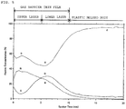
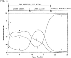
- Example 1 The surfaces of the thin films of the plastic bottles obtained at the first time of a series of film forming operations in Example 1 and Comparative Example 1 were analyzed using an XPS apparatus (type: QUANTERASXM, manufactured by ULVAC-PHI, Inc.). The ratios of constituent elements at the thin film surfaces are presented in Table 2. The conditions for the XPS analysis are as follows.
- the depth profiles of the thin films of the plastic bottles obtained at the first time of the series of film forming operations in Example 1 and Comparative Example 1 were analyzed using the above-described XPS apparatus while argon ion etching was performed.
- the test pieces and analysis conditions were the same as in the composition analysis.
- a 10-nm opposite side to the plastic molded body was regarded as an upper layer and a 10-nm plastic molded body side was regarded as a lower layer in Example 1 and 18-nm opposite side to the plastic molded body was regarded as an upper layer and a 18-nm plastic molded body side was regarded as a lower layer in Comparative Example 1.
- the O content percentage at Sputter Time 1.5 min was lower than the Si content percentage at Sputter Time 1.5 min. From this description, it was confirmed that in the composition in the extreme values of the O profile in the upper layer, the C content percentage is the highest, the Si content percentage is the secondary highest, and the O content percentage is the lowest in Example 1.
- the O content percentage at Sputter Time 6.0 min was lower than the Si content percentage at Sputter Time 6.0 min. From this description, it was confirmed that the Si content percentage is the highest in the composition in the extreme values of the O profile in the upper layer in Comparative Example 1.
- Example 1 as illustrated in Fig. 5 , the C content percentage at Sputter Time 6.0 min was higher than the Si content percentage at Sputter Time 6.0 min, and the O content percentage at Sputter Time 6.0 min was higher than the Si content percentage at Sputter Time 6.0 min.
- Comparative Example 1 as illustrated in Fig. 6 , the C content percentage at Sputter Time 13.5 min was lower than the Si content percentage at Sputter Time 13.5 min, and the O content percentage at Sputter Time 13.5 min was higher than the Si content percentage at Sputter Time 13.5 min.
- the transparency was evaluated by using the plastic bottles obtained at the first time of the series of film forming operations in Examples and Comparative Examples.
- the transparency was evaluated by the b* value.
- the b* value was measured using an automatic recording spectrophotometer (U-3900 type, manufactured by Hitachi, Ltd.) attached with a 60 ⁇ integrating sphere attachment device (for infrared/visible/near-infrared ranges) manufactured by the same company.
- an ultra-high sensitivity photomultiplier tube R928: for ultraviolet/visible ranges
- a cooling type PbS for near-infrared range
- the transmittance was measured in a wavelength range of from 380 nm to 780 nm.
- the transmittance measurement of the gas barrier thin film By measuring the transmittance of the PET bottle, the transmittance measurement of the gas barrier thin film only can be calculated; however, the b* value of this Example directly represents a value calculated in a form also involving the absorptivity of the PET bottle.
- the test pieces used in glossiness measurement were used for measurement. An average value of three test pieces was presented in Table 3 as the b* value.
- the gas barrier properties were evaluated using each plastic bottle obtained at the number of times of repetition of once, 100 times, and 200 times of the series of film forming operations in Examples and Comparative Examples.
- the gas barrier properties were evaluated by BIF.
- the oxygen permeability of each plastic bottle of Examples or Comparative Examples was measured.
- the oxygen permeability was measured using an oxygen permeability measuring apparatus (type: Oxtran 2/20, manufactured by Modern Controls, Inc.) under the conditions of 23°C and 90% RH, conditioning was carried out for 24 hours from the initiation of measurement and the oxygen permeability was designated as the value obtained after the passage of 72 hours from the initiation of measurement.
Landscapes
- Chemical & Material Sciences (AREA)
- Engineering & Computer Science (AREA)
- Mechanical Engineering (AREA)
- General Chemical & Material Sciences (AREA)
- Chemical Kinetics & Catalysis (AREA)
- Materials Engineering (AREA)
- Metallurgy (AREA)
- Organic Chemistry (AREA)
- Inorganic Chemistry (AREA)
- Laminated Bodies (AREA)
- Chemical Vapour Deposition (AREA)
- Details Of Rigid Or Semi-Rigid Containers (AREA)
Claims (7)
- Corps moulé en plastique faisant barrière contre les gaz comprenant un corps moulé en plastique et un film mince faisant barrière contre les gaz prévu sur une surface du corps moulé en plastique, dans lequel,
le film mince faisant barrière contre les gaz contient du silicium (Si), du carbone (C) et de l'oxygène (O) en tant qu'éléments constitutifs et a une région, dans laquelle un pic principal est observé, à une position d'apparition de pic d'énergie de liaison de Si-C lorsque le film mince faisant barrière contre les gaz est soumis à une analyse spectroscopique de photoélectrons X dans une condition (1) :
la plage de mesure est définie à une valeur de 95 à 105 eV. - Corps moulé en plastique faisant barrière contre les gaz selon la revendication 1, dans lequel
le film mince faisant barrière contre les gaz présente une composition à gradient dans une direction de la profondeur, et
lorsque le film mince faisant barrière contre les gaz est coupé en deux dans la direction de la profondeur de sorte qu'un côté opposé au corps moulé en plastique est considéré comme une couche supérieure et que le côté corps moulé en plastique est considéré comme une couche inférieure,
un pourcentage de contenu de C représenté par la formule mathématique 1 dans la couche supérieure est plus élevé qu'un pourcentage de contenu de Si représenté par la formule mathématique 2 dans la couche supérieure :

- Corps moulé en plastique faisant barrière contre les gaz selon la revendication 2, dans lequel
un pourcentage de contenu de O représenté par la formule mathématique 3 dans la couche supérieure est inférieur au pourcentage de contenu de Si dans la couche supérieure :
- Corps moulé en plastique faisant barrière contre les gaz selon l'une quelconque des revendications 1 à 3, dans lequel
le film mince faisant barrière contre les gaz présente une composition à gradient dans une direction de la profondeur, et
lorsque le film mince de barrière contre les gaz est coupé en deux dans la direction de la profondeur de sorte qu'un côté opposé au corps moulé en plastique est considéré comme une couche supérieure et que le côté corps moulé en plastique est considéré comme une couche inférieure,
un pourcentage de contenu de C représenté par la formule mathématique 1 dans la couche inférieure est plus élevé qu'un pourcentage de contenu de O représenté par la formule mathématique 3 dans la couche inférieure :

- Procédé de production d'un corps moulé en plastique faisant barrière contre les gaz selon la revendication 1, le procédé comprenant :une étape d'échappement consistant à assurer l'échappement du gaz à l'intérieur d'une chambre à vide pour ajuster l'intérieur de la chambre à vide à une pression initiale P0 de 1,5 Pa ou moins ;une étape de préparation consistant, lorsque la pression dans la chambre à vide est ajustée à P0 ou moins et qu'un élément de génération de chaleur, qui a une phase de carbure de tantale, disposé dans la chambre à vide n'est pas chauffé, à introduire de l'hydrocarbure gazeux contenant du silicium dans la chambre à vide pour ajuster la pression dans la chambre à vide à P0 ; etune étape de formation de film consistant à former un film mince faisant barrière contre les gaz sur une surface d'un corps moulé en plastique logé dans la chambre à vide par chauffage de l'élément de génération de chaleur alors que l'hydrocarbure gazeux contenant du silicium est introduit en continu dans la chambre à vide.
- Procédé de production d'un corps moulé en plastique faisant barrière contre les gaz selon la revendication 5, dans lequel
dans l'étape de préparation, la pression dans la chambre à vide est ajustée à P0 et puis la pression dans la chambre à vide est amenée à atteindre une pression PA supérieure à P0, et
dans l'étape de formation de film, la pression dans la chambre à vide est amenée à atteindre une pression PB supérieure à la PA. - Procédé de production d'un corps moulé en plastique faisant barrière contre les gaz selon la revendication 6, dans lequel (PB - PA)/P0 est 0,11 ou plus.
Applications Claiming Priority (2)
| Application Number | Priority Date | Filing Date | Title |
|---|---|---|---|
| JP2015085018A JP6474673B2 (ja) | 2015-04-17 | 2015-04-17 | ガスバリア性プラスチック成形体及びその製造方法 |
| PCT/JP2016/061070 WO2016167152A1 (fr) | 2015-04-17 | 2016-04-05 | Produit moulé en plastique faisant barrière contre les gaz et son procédé de fabrication |
Publications (3)
| Publication Number | Publication Date |
|---|---|
| EP3284846A1 EP3284846A1 (fr) | 2018-02-21 |
| EP3284846A4 EP3284846A4 (fr) | 2018-12-19 |
| EP3284846B1 true EP3284846B1 (fr) | 2021-02-17 |
Family
ID=57126273
Family Applications (1)
| Application Number | Title | Priority Date | Filing Date |
|---|---|---|---|
| EP16779943.6A Active EP3284846B1 (fr) | 2015-04-17 | 2016-04-05 | Produit moulé en plastique faisant barrière contre les gaz et son procédé de fabrication |
Country Status (11)
| Country | Link |
|---|---|
| US (1) | US10487397B2 (fr) |
| EP (1) | EP3284846B1 (fr) |
| JP (1) | JP6474673B2 (fr) |
| KR (1) | KR20170138476A (fr) |
| CN (1) | CN107429392B (fr) |
| AU (1) | AU2016248605A1 (fr) |
| MY (1) | MY186446A (fr) |
| PH (1) | PH12017501752A1 (fr) |
| SG (1) | SG11201708290QA (fr) |
| TW (1) | TWI686497B (fr) |
| WO (1) | WO2016167152A1 (fr) |
Families Citing this family (3)
| Publication number | Priority date | Publication date | Assignee | Title |
|---|---|---|---|---|
| AU2016220723A1 (en) * | 2015-02-18 | 2017-08-31 | Kirin Company, Limited | Heat generation element and method for producing same |
| JP2018095937A (ja) * | 2016-12-15 | 2018-06-21 | 三菱重工機械システム株式会社 | 電極状態評価装置、成膜装置及び電極状態評価方法 |
| JP7163041B2 (ja) * | 2018-03-13 | 2022-10-31 | 東レエンジニアリング株式会社 | バリアフィルムおよび光変換部材 |
Family Cites Families (13)
| Publication number | Priority date | Publication date | Assignee | Title |
|---|---|---|---|---|
| EP1317775A4 (fr) * | 2000-03-20 | 2009-01-28 | Bekaert Sa Nv | Materiels comportant des constantes dielectriques faibles et procede de production |
| JP2004107689A (ja) * | 2002-09-13 | 2004-04-08 | Ulvac Japan Ltd | ダイヤモンド状炭素膜形成方法及び製造装置 |
| US7288311B2 (en) * | 2003-02-10 | 2007-10-30 | Dai Nippon Printing Co., Ltd. | Barrier film |
| JP5260050B2 (ja) | 2005-05-27 | 2013-08-14 | 麒麟麦酒株式会社 | ガスバリア性プラスチック容器の製造装置及びその容器の製造方法 |
| JP5290564B2 (ja) * | 2007-11-13 | 2013-09-18 | トーヨーエイテック株式会社 | 炭素質薄膜 |
| WO2010067857A1 (fr) * | 2008-12-12 | 2010-06-17 | リンテック株式会社 | Stratifié, procédé pour sa production, élément de dispositif électronique et dispositif électronique |
| EP2433980B1 (fr) * | 2009-05-22 | 2019-07-10 | LINTEC Corporation | Objet moulé, son procédé de fabrication, élément pour un dispositif électronique et dispositif électronique |
| CA2822599C (fr) * | 2010-12-28 | 2015-11-24 | Kirin Beer Kabushiki Kaisha | Produit moule en matiere plastique a barriere contre les gaz et son procede de fabrication |
| SG191212A1 (en) * | 2010-12-28 | 2013-07-31 | Kirin Brewery | Method for producing gas barrier plastic molded body |
| JP5706777B2 (ja) * | 2011-07-25 | 2015-04-22 | 麒麟麦酒株式会社 | ガスバリア性プラスチック成形体 |
| WO2013099960A1 (fr) | 2011-12-27 | 2013-07-04 | 麒麟麦酒株式会社 | Appareil permettant de former un film mince |
| TWI576242B (zh) * | 2011-12-28 | 2017-04-01 | Kirin Brewery | Gas barrier plastic molded body and manufacturing method thereof |
| JP6009243B2 (ja) * | 2012-06-27 | 2016-10-19 | 麒麟麦酒株式会社 | 炭酸飲料用ボトル及びその製造方法 |
-
2015
- 2015-04-17 JP JP2015085018A patent/JP6474673B2/ja active Active
-
2016
- 2016-04-05 AU AU2016248605A patent/AU2016248605A1/en not_active Abandoned
- 2016-04-05 MY MYPI2017703465A patent/MY186446A/en unknown
- 2016-04-05 SG SG11201708290QA patent/SG11201708290QA/en unknown
- 2016-04-05 WO PCT/JP2016/061070 patent/WO2016167152A1/fr active Application Filing
- 2016-04-05 US US15/566,515 patent/US10487397B2/en active Active
- 2016-04-05 EP EP16779943.6A patent/EP3284846B1/fr active Active
- 2016-04-05 CN CN201680021428.1A patent/CN107429392B/zh active Active
- 2016-04-05 KR KR1020177032902A patent/KR20170138476A/ko unknown
- 2016-04-11 TW TW105111263A patent/TWI686497B/zh not_active IP Right Cessation
-
2017
- 2017-09-25 PH PH12017501752A patent/PH12017501752A1/en unknown
Also Published As
| Publication number | Publication date |
|---|---|
| CN107429392A (zh) | 2017-12-01 |
| EP3284846A1 (fr) | 2018-02-21 |
| US10487397B2 (en) | 2019-11-26 |
| TW201641732A (zh) | 2016-12-01 |
| WO2016167152A1 (fr) | 2016-10-20 |
| KR20170138476A (ko) | 2017-12-15 |
| PH12017501752A1 (en) | 2018-04-11 |
| JP6474673B2 (ja) | 2019-02-27 |
| SG11201708290QA (en) | 2017-11-29 |
| EP3284846A4 (fr) | 2018-12-19 |
| AU2016248605A1 (en) | 2017-10-19 |
| TWI686497B (zh) | 2020-03-01 |
| JP2016204685A (ja) | 2016-12-08 |
| MY186446A (en) | 2021-07-22 |
| US20180127872A1 (en) | 2018-05-10 |
| CN107429392B (zh) | 2019-08-20 |
Similar Documents
| Publication | Publication Date | Title |
|---|---|---|
| AU2011350429B2 (en) | Gas-barrier plastic molded product and manufacturing process therefor | |
| EP3284846B1 (fr) | Produit moulé en plastique faisant barrière contre les gaz et son procédé de fabrication | |
| JP4426790B2 (ja) | 多層バリヤ層を作製するための高速処理法 | |
| EP2135734B1 (fr) | Plastique moulé avec film déposé en phase vapeur et processus de production de celui-ci | |
| AU2011350427B2 (en) | Method for producing gas barrier plastic molded body | |
| JP2010158832A (ja) | ガスバリア性フィルム | |
| JP2012206507A (ja) | ガスバリア性フィルム | |
| JP5706777B2 (ja) | ガスバリア性プラスチック成形体 | |
| TW201609427A (zh) | 積層體及其製造方法、以及阻氣性薄膜及其製造方法 | |
| Patelli et al. | SiOx‐based multilayer barrier coatings produced by a single PECVD process | |
| JP5566334B2 (ja) | ガスバリア性プラスチック成形体及びその製造方法 | |
| JP7005256B2 (ja) | ガスバリア性容器 | |
| TWI576242B (zh) | Gas barrier plastic molded body and manufacturing method thereof | |
| TWI537415B (zh) | Production method of gas barrier plastic molded body | |
| JP2013044021A (ja) | 濡れ性の制御方法 | |
| JP2020158127A (ja) | ガスバリア性容器およびガスバリア性容器の製造方法 |
Legal Events
| Date | Code | Title | Description |
|---|---|---|---|
| STAA | Information on the status of an ep patent application or granted ep patent |
Free format text: STATUS: THE INTERNATIONAL PUBLICATION HAS BEEN MADE |
|
| PUAI | Public reference made under article 153(3) epc to a published international application that has entered the european phase |
Free format text: ORIGINAL CODE: 0009012 |
|
| STAA | Information on the status of an ep patent application or granted ep patent |
Free format text: STATUS: REQUEST FOR EXAMINATION WAS MADE |
|
| 17P | Request for examination filed |
Effective date: 20171019 |
|
| AK | Designated contracting states |
Kind code of ref document: A1 Designated state(s): AL AT BE BG CH CY CZ DE DK EE ES FI FR GB GR HR HU IE IS IT LI LT LU LV MC MK MT NL NO PL PT RO RS SE SI SK SM TR |
|
| AX | Request for extension of the european patent |
Extension state: BA ME |
|
| DAV | Request for validation of the european patent (deleted) | ||
| DAX | Request for extension of the european patent (deleted) | ||
| A4 | Supplementary search report drawn up and despatched |
Effective date: 20181120 |
|
| RIC1 | Information provided on ipc code assigned before grant |
Ipc: B65D 23/02 20060101ALI20181114BHEP Ipc: C23C 16/32 20060101ALI20181114BHEP Ipc: C23C 16/30 20060101ALI20181114BHEP Ipc: C23C 16/40 20060101ALI20181114BHEP Ipc: C23C 16/44 20060101ALI20181114BHEP Ipc: C23C 16/42 20060101AFI20181114BHEP Ipc: C23C 16/452 20060101ALI20181114BHEP Ipc: C23C 16/448 20060101ALI20181114BHEP |
|
| RAP1 | Party data changed (applicant data changed or rights of an application transferred) |
Owner name: KIRIN HOLDINGS KABUSHIKI KAISHA |
|
| REG | Reference to a national code |
Ref country code: DE Ref legal event code: R079 Ref document number: 602016052641 Country of ref document: DE Free format text: PREVIOUS MAIN CLASS: C23C0016420000 Ipc: C23C0016300000 |
|
| RIC1 | Information provided on ipc code assigned before grant |
Ipc: C23C 16/04 20060101ALI20200717BHEP Ipc: C23C 16/40 20060101ALI20200717BHEP Ipc: C23C 16/448 20060101ALI20200717BHEP Ipc: C23C 16/32 20060101ALI20200717BHEP Ipc: C23C 16/30 20060101AFI20200717BHEP Ipc: B65D 23/02 20060101ALI20200717BHEP |
|
| GRAP | Despatch of communication of intention to grant a patent |
Free format text: ORIGINAL CODE: EPIDOSNIGR1 |
|
| STAA | Information on the status of an ep patent application or granted ep patent |
Free format text: STATUS: GRANT OF PATENT IS INTENDED |
|
| INTG | Intention to grant announced |
Effective date: 20200831 |
|
| GRAS | Grant fee paid |
Free format text: ORIGINAL CODE: EPIDOSNIGR3 |
|
| GRAA | (expected) grant |
Free format text: ORIGINAL CODE: 0009210 |
|
| STAA | Information on the status of an ep patent application or granted ep patent |
Free format text: STATUS: THE PATENT HAS BEEN GRANTED |
|
| AK | Designated contracting states |
Kind code of ref document: B1 Designated state(s): AL AT BE BG CH CY CZ DE DK EE ES FI FR GB GR HR HU IE IS IT LI LT LU LV MC MK MT NL NO PL PT RO RS SE SI SK SM TR |
|
| REG | Reference to a national code |
Ref country code: GB Ref legal event code: FG4D |
|
| REG | Reference to a national code |
Ref country code: CH Ref legal event code: EP |
|
| REG | Reference to a national code |
Ref country code: DE Ref legal event code: R096 Ref document number: 602016052641 Country of ref document: DE |
|
| REG | Reference to a national code |
Ref country code: AT Ref legal event code: REF Ref document number: 1361555 Country of ref document: AT Kind code of ref document: T Effective date: 20210315 |
|
| REG | Reference to a national code |
Ref country code: IE Ref legal event code: FG4D |
|
| REG | Reference to a national code |
Ref country code: LT Ref legal event code: MG9D |
|
| REG | Reference to a national code |
Ref country code: NL Ref legal event code: MP Effective date: 20210217 |
|
| PG25 | Lapsed in a contracting state [announced via postgrant information from national office to epo] |
Ref country code: BG Free format text: LAPSE BECAUSE OF FAILURE TO SUBMIT A TRANSLATION OF THE DESCRIPTION OR TO PAY THE FEE WITHIN THE PRESCRIBED TIME-LIMIT Effective date: 20210517 Ref country code: LT Free format text: LAPSE BECAUSE OF FAILURE TO SUBMIT A TRANSLATION OF THE DESCRIPTION OR TO PAY THE FEE WITHIN THE PRESCRIBED TIME-LIMIT Effective date: 20210217 Ref country code: HR Free format text: LAPSE BECAUSE OF FAILURE TO SUBMIT A TRANSLATION OF THE DESCRIPTION OR TO PAY THE FEE WITHIN THE PRESCRIBED TIME-LIMIT Effective date: 20210217 Ref country code: FI Free format text: LAPSE BECAUSE OF FAILURE TO SUBMIT A TRANSLATION OF THE DESCRIPTION OR TO PAY THE FEE WITHIN THE PRESCRIBED TIME-LIMIT Effective date: 20210217 Ref country code: GR Free format text: LAPSE BECAUSE OF FAILURE TO SUBMIT A TRANSLATION OF THE DESCRIPTION OR TO PAY THE FEE WITHIN THE PRESCRIBED TIME-LIMIT Effective date: 20210518 Ref country code: PT Free format text: LAPSE BECAUSE OF FAILURE TO SUBMIT A TRANSLATION OF THE DESCRIPTION OR TO PAY THE FEE WITHIN THE PRESCRIBED TIME-LIMIT Effective date: 20210617 Ref country code: NO Free format text: LAPSE BECAUSE OF FAILURE TO SUBMIT A TRANSLATION OF THE DESCRIPTION OR TO PAY THE FEE WITHIN THE PRESCRIBED TIME-LIMIT Effective date: 20210517 |
|
| REG | Reference to a national code |
Ref country code: AT Ref legal event code: MK05 Ref document number: 1361555 Country of ref document: AT Kind code of ref document: T Effective date: 20210217 |
|
| PG25 | Lapsed in a contracting state [announced via postgrant information from national office to epo] |
Ref country code: SE Free format text: LAPSE BECAUSE OF FAILURE TO SUBMIT A TRANSLATION OF THE DESCRIPTION OR TO PAY THE FEE WITHIN THE PRESCRIBED TIME-LIMIT Effective date: 20210217 Ref country code: RS Free format text: LAPSE BECAUSE OF FAILURE TO SUBMIT A TRANSLATION OF THE DESCRIPTION OR TO PAY THE FEE WITHIN THE PRESCRIBED TIME-LIMIT Effective date: 20210217 Ref country code: NL Free format text: LAPSE BECAUSE OF FAILURE TO SUBMIT A TRANSLATION OF THE DESCRIPTION OR TO PAY THE FEE WITHIN THE PRESCRIBED TIME-LIMIT Effective date: 20210217 Ref country code: LV Free format text: LAPSE BECAUSE OF FAILURE TO SUBMIT A TRANSLATION OF THE DESCRIPTION OR TO PAY THE FEE WITHIN THE PRESCRIBED TIME-LIMIT Effective date: 20210217 Ref country code: PL Free format text: LAPSE BECAUSE OF FAILURE TO SUBMIT A TRANSLATION OF THE DESCRIPTION OR TO PAY THE FEE WITHIN THE PRESCRIBED TIME-LIMIT Effective date: 20210217 |
|
| PG25 | Lapsed in a contracting state [announced via postgrant information from national office to epo] |
Ref country code: IS Free format text: LAPSE BECAUSE OF FAILURE TO SUBMIT A TRANSLATION OF THE DESCRIPTION OR TO PAY THE FEE WITHIN THE PRESCRIBED TIME-LIMIT Effective date: 20210617 |
|
| PG25 | Lapsed in a contracting state [announced via postgrant information from national office to epo] |
Ref country code: EE Free format text: LAPSE BECAUSE OF FAILURE TO SUBMIT A TRANSLATION OF THE DESCRIPTION OR TO PAY THE FEE WITHIN THE PRESCRIBED TIME-LIMIT Effective date: 20210217 Ref country code: CZ Free format text: LAPSE BECAUSE OF FAILURE TO SUBMIT A TRANSLATION OF THE DESCRIPTION OR TO PAY THE FEE WITHIN THE PRESCRIBED TIME-LIMIT Effective date: 20210217 Ref country code: SM Free format text: LAPSE BECAUSE OF FAILURE TO SUBMIT A TRANSLATION OF THE DESCRIPTION OR TO PAY THE FEE WITHIN THE PRESCRIBED TIME-LIMIT Effective date: 20210217 Ref country code: AT Free format text: LAPSE BECAUSE OF FAILURE TO SUBMIT A TRANSLATION OF THE DESCRIPTION OR TO PAY THE FEE WITHIN THE PRESCRIBED TIME-LIMIT Effective date: 20210217 |
|
| REG | Reference to a national code |
Ref country code: DE Ref legal event code: R097 Ref document number: 602016052641 Country of ref document: DE |
|
| PG25 | Lapsed in a contracting state [announced via postgrant information from national office to epo] |
Ref country code: SK Free format text: LAPSE BECAUSE OF FAILURE TO SUBMIT A TRANSLATION OF THE DESCRIPTION OR TO PAY THE FEE WITHIN THE PRESCRIBED TIME-LIMIT Effective date: 20210217 Ref country code: RO Free format text: LAPSE BECAUSE OF FAILURE TO SUBMIT A TRANSLATION OF THE DESCRIPTION OR TO PAY THE FEE WITHIN THE PRESCRIBED TIME-LIMIT Effective date: 20210217 Ref country code: DK Free format text: LAPSE BECAUSE OF FAILURE TO SUBMIT A TRANSLATION OF THE DESCRIPTION OR TO PAY THE FEE WITHIN THE PRESCRIBED TIME-LIMIT Effective date: 20210217 Ref country code: MC Free format text: LAPSE BECAUSE OF FAILURE TO SUBMIT A TRANSLATION OF THE DESCRIPTION OR TO PAY THE FEE WITHIN THE PRESCRIBED TIME-LIMIT Effective date: 20210217 |
|
| PLBE | No opposition filed within time limit |
Free format text: ORIGINAL CODE: 0009261 |
|
| STAA | Information on the status of an ep patent application or granted ep patent |
Free format text: STATUS: NO OPPOSITION FILED WITHIN TIME LIMIT |
|
| PG25 | Lapsed in a contracting state [announced via postgrant information from national office to epo] |
Ref country code: LU Free format text: LAPSE BECAUSE OF NON-PAYMENT OF DUE FEES Effective date: 20210405 |
|
| REG | Reference to a national code |
Ref country code: BE Ref legal event code: MM Effective date: 20210430 |
|
| 26N | No opposition filed |
Effective date: 20211118 |
|
| GBPC | Gb: european patent ceased through non-payment of renewal fee |
Effective date: 20210517 |
|
| PG25 | Lapsed in a contracting state [announced via postgrant information from national office to epo] |
Ref country code: ES Free format text: LAPSE BECAUSE OF FAILURE TO SUBMIT A TRANSLATION OF THE DESCRIPTION OR TO PAY THE FEE WITHIN THE PRESCRIBED TIME-LIMIT Effective date: 20210217 Ref country code: LI Free format text: LAPSE BECAUSE OF NON-PAYMENT OF DUE FEES Effective date: 20210430 Ref country code: CH Free format text: LAPSE BECAUSE OF NON-PAYMENT OF DUE FEES Effective date: 20210430 Ref country code: AL Free format text: LAPSE BECAUSE OF FAILURE TO SUBMIT A TRANSLATION OF THE DESCRIPTION OR TO PAY THE FEE WITHIN THE PRESCRIBED TIME-LIMIT Effective date: 20210217 |
|
| PG25 | Lapsed in a contracting state [announced via postgrant information from national office to epo] |
Ref country code: SI Free format text: LAPSE BECAUSE OF FAILURE TO SUBMIT A TRANSLATION OF THE DESCRIPTION OR TO PAY THE FEE WITHIN THE PRESCRIBED TIME-LIMIT Effective date: 20210217 |
|
| PG25 | Lapsed in a contracting state [announced via postgrant information from national office to epo] |
Ref country code: IT Free format text: LAPSE BECAUSE OF FAILURE TO SUBMIT A TRANSLATION OF THE DESCRIPTION OR TO PAY THE FEE WITHIN THE PRESCRIBED TIME-LIMIT Effective date: 20210217 Ref country code: IE Free format text: LAPSE BECAUSE OF NON-PAYMENT OF DUE FEES Effective date: 20210405 Ref country code: GB Free format text: LAPSE BECAUSE OF NON-PAYMENT OF DUE FEES Effective date: 20210517 |
|
| PG25 | Lapsed in a contracting state [announced via postgrant information from national office to epo] |
Ref country code: IS Free format text: LAPSE BECAUSE OF FAILURE TO SUBMIT A TRANSLATION OF THE DESCRIPTION OR TO PAY THE FEE WITHIN THE PRESCRIBED TIME-LIMIT Effective date: 20210617 |
|
| PG25 | Lapsed in a contracting state [announced via postgrant information from national office to epo] |
Ref country code: BE Free format text: LAPSE BECAUSE OF NON-PAYMENT OF DUE FEES Effective date: 20210430 |
|
| REG | Reference to a national code |
Ref country code: FR Ref legal event code: PLFP Year of fee payment: 8 |
|
| PG25 | Lapsed in a contracting state [announced via postgrant information from national office to epo] |
Ref country code: HU Free format text: LAPSE BECAUSE OF FAILURE TO SUBMIT A TRANSLATION OF THE DESCRIPTION OR TO PAY THE FEE WITHIN THE PRESCRIBED TIME-LIMIT; INVALID AB INITIO Effective date: 20160405 |
|
| P01 | Opt-out of the competence of the unified patent court (upc) registered |
Effective date: 20230411 |
|
| PG25 | Lapsed in a contracting state [announced via postgrant information from national office to epo] |
Ref country code: CY Free format text: LAPSE BECAUSE OF FAILURE TO SUBMIT A TRANSLATION OF THE DESCRIPTION OR TO PAY THE FEE WITHIN THE PRESCRIBED TIME-LIMIT Effective date: 20210217 |
|
| PGFP | Annual fee paid to national office [announced via postgrant information from national office to epo] |
Ref country code: FR Payment date: 20230412 Year of fee payment: 8 Ref country code: DE Payment date: 20230414 Year of fee payment: 8 |
|
| PG25 | Lapsed in a contracting state [announced via postgrant information from national office to epo] |
Ref country code: MK Free format text: LAPSE BECAUSE OF FAILURE TO SUBMIT A TRANSLATION OF THE DESCRIPTION OR TO PAY THE FEE WITHIN THE PRESCRIBED TIME-LIMIT Effective date: 20210217 |