WO2016167065A1 - バルブ装置及び流体圧制御装置 - Google Patents
バルブ装置及び流体圧制御装置 Download PDFInfo
- Publication number
- WO2016167065A1 WO2016167065A1 PCT/JP2016/057998 JP2016057998W WO2016167065A1 WO 2016167065 A1 WO2016167065 A1 WO 2016167065A1 JP 2016057998 W JP2016057998 W JP 2016057998W WO 2016167065 A1 WO2016167065 A1 WO 2016167065A1
- Authority
- WO
- WIPO (PCT)
- Prior art keywords
- valve
- chamber
- drain
- passage
- valve body
- Prior art date
- Legal status (The legal status is an assumption and is not a legal conclusion. Google has not performed a legal analysis and makes no representation as to the accuracy of the status listed.)
- Ceased
Links
Images




Classifications
-
- F—MECHANICAL ENGINEERING; LIGHTING; HEATING; WEAPONS; BLASTING
- F15—FLUID-PRESSURE ACTUATORS; HYDRAULICS OR PNEUMATICS IN GENERAL
- F15B—SYSTEMS ACTING BY MEANS OF FLUIDS IN GENERAL; FLUID-PRESSURE ACTUATORS, e.g. SERVOMOTORS; DETAILS OF FLUID-PRESSURE SYSTEMS, NOT OTHERWISE PROVIDED FOR
- F15B11/00—Servomotor systems without provision for follow-up action; Circuits therefor
- F15B11/02—Systems essentially incorporating special features for controlling the speed or actuating force of an output member
- F15B11/028—Systems essentially incorporating special features for controlling the speed or actuating force of an output member for controlling the actuating force
-
- E—FIXED CONSTRUCTIONS
- E02—HYDRAULIC ENGINEERING; FOUNDATIONS; SOIL SHIFTING
- E02F—DREDGING; SOIL-SHIFTING
- E02F9/00—Component parts of dredgers or soil-shifting machines, not restricted to one of the kinds covered by groups E02F3/00 - E02F7/00
- E02F9/20—Drives; Control devices
- E02F9/22—Hydraulic or pneumatic drives
- E02F9/2221—Control of flow rate; Load sensing arrangements
-
- E—FIXED CONSTRUCTIONS
- E02—HYDRAULIC ENGINEERING; FOUNDATIONS; SOIL SHIFTING
- E02F—DREDGING; SOIL-SHIFTING
- E02F9/00—Component parts of dredgers or soil-shifting machines, not restricted to one of the kinds covered by groups E02F3/00 - E02F7/00
- E02F9/20—Drives; Control devices
- E02F9/22—Hydraulic or pneumatic drives
- E02F9/2221—Control of flow rate; Load sensing arrangements
- E02F9/2225—Control of flow rate; Load sensing arrangements using pressure-compensating valves
-
- E—FIXED CONSTRUCTIONS
- E02—HYDRAULIC ENGINEERING; FOUNDATIONS; SOIL SHIFTING
- E02F—DREDGING; SOIL-SHIFTING
- E02F9/00—Component parts of dredgers or soil-shifting machines, not restricted to one of the kinds covered by groups E02F3/00 - E02F7/00
- E02F9/20—Drives; Control devices
- E02F9/22—Hydraulic or pneumatic drives
- E02F9/2264—Arrangements or adaptations of elements for hydraulic drives
- E02F9/2267—Valves or distributors
-
- F—MECHANICAL ENGINEERING; LIGHTING; HEATING; WEAPONS; BLASTING
- F15—FLUID-PRESSURE ACTUATORS; HYDRAULICS OR PNEUMATICS IN GENERAL
- F15B—SYSTEMS ACTING BY MEANS OF FLUIDS IN GENERAL; FLUID-PRESSURE ACTUATORS, e.g. SERVOMOTORS; DETAILS OF FLUID-PRESSURE SYSTEMS, NOT OTHERWISE PROVIDED FOR
- F15B11/00—Servomotor systems without provision for follow-up action; Circuits therefor
- F15B11/003—Systems with load-holding valves
-
- F—MECHANICAL ENGINEERING; LIGHTING; HEATING; WEAPONS; BLASTING
- F15—FLUID-PRESSURE ACTUATORS; HYDRAULICS OR PNEUMATICS IN GENERAL
- F15B—SYSTEMS ACTING BY MEANS OF FLUIDS IN GENERAL; FLUID-PRESSURE ACTUATORS, e.g. SERVOMOTORS; DETAILS OF FLUID-PRESSURE SYSTEMS, NOT OTHERWISE PROVIDED FOR
- F15B11/00—Servomotor systems without provision for follow-up action; Circuits therefor
- F15B11/02—Systems essentially incorporating special features for controlling the speed or actuating force of an output member
-
- F—MECHANICAL ENGINEERING; LIGHTING; HEATING; WEAPONS; BLASTING
- F15—FLUID-PRESSURE ACTUATORS; HYDRAULICS OR PNEUMATICS IN GENERAL
- F15B—SYSTEMS ACTING BY MEANS OF FLUIDS IN GENERAL; FLUID-PRESSURE ACTUATORS, e.g. SERVOMOTORS; DETAILS OF FLUID-PRESSURE SYSTEMS, NOT OTHERWISE PROVIDED FOR
- F15B21/00—Common features of fluid actuator systems; Fluid-pressure actuator systems or details thereof, not covered by any other group of this subclass
- F15B21/005—Filling or draining of fluid systems
-
- F—MECHANICAL ENGINEERING; LIGHTING; HEATING; WEAPONS; BLASTING
- F16—ENGINEERING ELEMENTS AND UNITS; GENERAL MEASURES FOR PRODUCING AND MAINTAINING EFFECTIVE FUNCTIONING OF MACHINES OR INSTALLATIONS; THERMAL INSULATION IN GENERAL
- F16K—VALVES; TAPS; COCKS; ACTUATING-FLOATS; DEVICES FOR VENTING OR AERATING
- F16K11/00—Multiple-way valves, e.g. mixing valves; Pipe fittings incorporating such valves
- F16K11/02—Multiple-way valves, e.g. mixing valves; Pipe fittings incorporating such valves with all movable sealing faces moving as one unit
- F16K11/06—Multiple-way valves, e.g. mixing valves; Pipe fittings incorporating such valves with all movable sealing faces moving as one unit comprising only sliding valves, i.e. sliding closure elements
- F16K11/065—Multiple-way valves, e.g. mixing valves; Pipe fittings incorporating such valves with all movable sealing faces moving as one unit comprising only sliding valves, i.e. sliding closure elements with linearly sliding closure members
- F16K11/07—Multiple-way valves, e.g. mixing valves; Pipe fittings incorporating such valves with all movable sealing faces moving as one unit comprising only sliding valves, i.e. sliding closure elements with linearly sliding closure members with cylindrical slides
-
- F—MECHANICAL ENGINEERING; LIGHTING; HEATING; WEAPONS; BLASTING
- F16—ENGINEERING ELEMENTS AND UNITS; GENERAL MEASURES FOR PRODUCING AND MAINTAINING EFFECTIVE FUNCTIONING OF MACHINES OR INSTALLATIONS; THERMAL INSULATION IN GENERAL
- F16K—VALVES; TAPS; COCKS; ACTUATING-FLOATS; DEVICES FOR VENTING OR AERATING
- F16K31/00—Actuating devices; Operating means; Releasing devices
- F16K31/12—Actuating devices; Operating means; Releasing devices actuated by fluid
- F16K31/36—Actuating devices; Operating means; Releasing devices actuated by fluid in which fluid from the circuit is constantly supplied to the fluid motor
- F16K31/363—Actuating devices; Operating means; Releasing devices actuated by fluid in which fluid from the circuit is constantly supplied to the fluid motor the fluid acting on a piston
-
- E—FIXED CONSTRUCTIONS
- E02—HYDRAULIC ENGINEERING; FOUNDATIONS; SOIL SHIFTING
- E02F—DREDGING; SOIL-SHIFTING
- E02F9/00—Component parts of dredgers or soil-shifting machines, not restricted to one of the kinds covered by groups E02F3/00 - E02F7/00
- E02F9/20—Drives; Control devices
- E02F9/22—Hydraulic or pneumatic drives
- E02F9/2203—Arrangements for controlling the attitude of actuators, e.g. speed, floating function
-
- E—FIXED CONSTRUCTIONS
- E02—HYDRAULIC ENGINEERING; FOUNDATIONS; SOIL SHIFTING
- E02F—DREDGING; SOIL-SHIFTING
- E02F9/00—Component parts of dredgers or soil-shifting machines, not restricted to one of the kinds covered by groups E02F3/00 - E02F7/00
- E02F9/20—Drives; Control devices
- E02F9/22—Hydraulic or pneumatic drives
- E02F9/2278—Hydraulic circuits
- E02F9/2282—Systems using center bypass type changeover valves
-
- E—FIXED CONSTRUCTIONS
- E02—HYDRAULIC ENGINEERING; FOUNDATIONS; SOIL SHIFTING
- E02F—DREDGING; SOIL-SHIFTING
- E02F9/00—Component parts of dredgers or soil-shifting machines, not restricted to one of the kinds covered by groups E02F3/00 - E02F7/00
- E02F9/20—Drives; Control devices
- E02F9/22—Hydraulic or pneumatic drives
- E02F9/2278—Hydraulic circuits
- E02F9/2285—Pilot-operated systems
-
- F—MECHANICAL ENGINEERING; LIGHTING; HEATING; WEAPONS; BLASTING
- F15—FLUID-PRESSURE ACTUATORS; HYDRAULICS OR PNEUMATICS IN GENERAL
- F15B—SYSTEMS ACTING BY MEANS OF FLUIDS IN GENERAL; FLUID-PRESSURE ACTUATORS, e.g. SERVOMOTORS; DETAILS OF FLUID-PRESSURE SYSTEMS, NOT OTHERWISE PROVIDED FOR
- F15B13/00—Details of servomotor systems ; Valves for servomotor systems
- F15B13/02—Fluid distribution or supply devices characterised by their adaptation to the control of servomotors
- F15B13/04—Fluid distribution or supply devices characterised by their adaptation to the control of servomotors for use with a single servomotor
- F15B13/0401—Valve members; Fluid interconnections therefor
- F15B13/0402—Valve members; Fluid interconnections therefor for linearly sliding valves, e.g. spool valves
-
- F—MECHANICAL ENGINEERING; LIGHTING; HEATING; WEAPONS; BLASTING
- F15—FLUID-PRESSURE ACTUATORS; HYDRAULICS OR PNEUMATICS IN GENERAL
- F15B—SYSTEMS ACTING BY MEANS OF FLUIDS IN GENERAL; FLUID-PRESSURE ACTUATORS, e.g. SERVOMOTORS; DETAILS OF FLUID-PRESSURE SYSTEMS, NOT OTHERWISE PROVIDED FOR
- F15B13/00—Details of servomotor systems ; Valves for servomotor systems
- F15B13/02—Fluid distribution or supply devices characterised by their adaptation to the control of servomotors
- F15B13/04—Fluid distribution or supply devices characterised by their adaptation to the control of servomotors for use with a single servomotor
- F15B13/042—Fluid distribution or supply devices characterised by their adaptation to the control of servomotors for use with a single servomotor operated by fluid pressure
- F15B13/0422—Fluid distribution or supply devices characterised by their adaptation to the control of servomotors for use with a single servomotor operated by fluid pressure with manually-operated pilot valves, e.g. joysticks
-
- F—MECHANICAL ENGINEERING; LIGHTING; HEATING; WEAPONS; BLASTING
- F15—FLUID-PRESSURE ACTUATORS; HYDRAULICS OR PNEUMATICS IN GENERAL
- F15B—SYSTEMS ACTING BY MEANS OF FLUIDS IN GENERAL; FLUID-PRESSURE ACTUATORS, e.g. SERVOMOTORS; DETAILS OF FLUID-PRESSURE SYSTEMS, NOT OTHERWISE PROVIDED FOR
- F15B2211/00—Circuits for servomotor systems
- F15B2211/30—Directional control
- F15B2211/305—Directional control characterised by the type of valves
- F15B2211/30505—Non-return valves, i.e. check valves
- F15B2211/30515—Load holding valves
-
- F—MECHANICAL ENGINEERING; LIGHTING; HEATING; WEAPONS; BLASTING
- F15—FLUID-PRESSURE ACTUATORS; HYDRAULICS OR PNEUMATICS IN GENERAL
- F15B—SYSTEMS ACTING BY MEANS OF FLUIDS IN GENERAL; FLUID-PRESSURE ACTUATORS, e.g. SERVOMOTORS; DETAILS OF FLUID-PRESSURE SYSTEMS, NOT OTHERWISE PROVIDED FOR
- F15B2211/00—Circuits for servomotor systems
- F15B2211/30—Directional control
- F15B2211/31—Directional control characterised by the positions of the valve element
- F15B2211/3105—Neutral or centre positions
- F15B2211/3116—Neutral or centre positions the pump port being open in the centre position, e.g. so-called open centre
-
- F—MECHANICAL ENGINEERING; LIGHTING; HEATING; WEAPONS; BLASTING
- F15—FLUID-PRESSURE ACTUATORS; HYDRAULICS OR PNEUMATICS IN GENERAL
- F15B—SYSTEMS ACTING BY MEANS OF FLUIDS IN GENERAL; FLUID-PRESSURE ACTUATORS, e.g. SERVOMOTORS; DETAILS OF FLUID-PRESSURE SYSTEMS, NOT OTHERWISE PROVIDED FOR
- F15B2211/00—Circuits for servomotor systems
- F15B2211/30—Directional control
- F15B2211/32—Directional control characterised by the type of actuation
- F15B2211/329—Directional control characterised by the type of actuation actuated by fluid pressure
-
- F—MECHANICAL ENGINEERING; LIGHTING; HEATING; WEAPONS; BLASTING
- F15—FLUID-PRESSURE ACTUATORS; HYDRAULICS OR PNEUMATICS IN GENERAL
- F15B—SYSTEMS ACTING BY MEANS OF FLUIDS IN GENERAL; FLUID-PRESSURE ACTUATORS, e.g. SERVOMOTORS; DETAILS OF FLUID-PRESSURE SYSTEMS, NOT OTHERWISE PROVIDED FOR
- F15B2211/00—Circuits for servomotor systems
- F15B2211/30—Directional control
- F15B2211/355—Pilot pressure control
-
- F—MECHANICAL ENGINEERING; LIGHTING; HEATING; WEAPONS; BLASTING
- F15—FLUID-PRESSURE ACTUATORS; HYDRAULICS OR PNEUMATICS IN GENERAL
- F15B—SYSTEMS ACTING BY MEANS OF FLUIDS IN GENERAL; FLUID-PRESSURE ACTUATORS, e.g. SERVOMOTORS; DETAILS OF FLUID-PRESSURE SYSTEMS, NOT OTHERWISE PROVIDED FOR
- F15B2211/00—Circuits for servomotor systems
- F15B2211/40—Flow control
- F15B2211/405—Flow control characterised by the type of flow control means or valve
-
- F—MECHANICAL ENGINEERING; LIGHTING; HEATING; WEAPONS; BLASTING
- F15—FLUID-PRESSURE ACTUATORS; HYDRAULICS OR PNEUMATICS IN GENERAL
- F15B—SYSTEMS ACTING BY MEANS OF FLUIDS IN GENERAL; FLUID-PRESSURE ACTUATORS, e.g. SERVOMOTORS; DETAILS OF FLUID-PRESSURE SYSTEMS, NOT OTHERWISE PROVIDED FOR
- F15B2211/00—Circuits for servomotor systems
- F15B2211/40—Flow control
- F15B2211/415—Flow control characterised by the connections of the flow control means in the circuit
- F15B2211/41554—Flow control characterised by the connections of the flow control means in the circuit being connected to a return line and a directional control valve
-
- F—MECHANICAL ENGINEERING; LIGHTING; HEATING; WEAPONS; BLASTING
- F15—FLUID-PRESSURE ACTUATORS; HYDRAULICS OR PNEUMATICS IN GENERAL
- F15B—SYSTEMS ACTING BY MEANS OF FLUIDS IN GENERAL; FLUID-PRESSURE ACTUATORS, e.g. SERVOMOTORS; DETAILS OF FLUID-PRESSURE SYSTEMS, NOT OTHERWISE PROVIDED FOR
- F15B2211/00—Circuits for servomotor systems
- F15B2211/40—Flow control
- F15B2211/42—Flow control characterised by the type of actuation
- F15B2211/428—Flow control characterised by the type of actuation actuated by fluid pressure
-
- F—MECHANICAL ENGINEERING; LIGHTING; HEATING; WEAPONS; BLASTING
- F15—FLUID-PRESSURE ACTUATORS; HYDRAULICS OR PNEUMATICS IN GENERAL
- F15B—SYSTEMS ACTING BY MEANS OF FLUIDS IN GENERAL; FLUID-PRESSURE ACTUATORS, e.g. SERVOMOTORS; DETAILS OF FLUID-PRESSURE SYSTEMS, NOT OTHERWISE PROVIDED FOR
- F15B2211/00—Circuits for servomotor systems
- F15B2211/40—Flow control
- F15B2211/45—Control of bleed-off flow, e.g. control of bypass flow to the return line
Definitions
- the present invention relates to a valve device including a drain port and a fluid pressure control device including the valve device.
- JP2008-202724A discloses a spring return type control valve as an example of a valve device.
- the control valve includes a valve body (spool) housed in a sliding hole of the valve body, a pilot chamber formed at one end of the sliding hole, a drain chamber formed at the other end of the sliding hole, and a pilot And a return spring housed in the chamber.
- the spool moves to the drain chamber side due to the pilot pressure.
- the spool moves to the pilot chamber side by the restoring force of the return spring.
- Drain port is formed on the drain chamber wall that divides the drain chamber. The hydraulic oil in the drain chamber is discharged as drain to the tank through the drain port.
- control valve disclosed in JP2008-202724A is applied to one of the plurality of valve devices, and the drains of the other valve devices are connected to the drain chamber of the aforementioned one valve device. It is conceivable to form a guide passage in the valve body.
- the drain chamber wall functions as a movement restriction unit that contacts the spool and restricts the movement of the spool.
- the drain port is formed on the drain chamber wall so as to face the spool, the drain port is closed by the spool contacting the drain chamber wall. That is, depending on the position of the spool, drains of other valve devices are not discharged from the drain port.
- An object of the present invention is to provide a valve device and a fluid pressure control device capable of discharging the drain of another valve device from the drain port regardless of the position of the valve body.
- a valve device includes: a valve body that is movably accommodated in the valve body; a drain chamber wall that defines a drain chamber into which the valve body enters and exits as the valve body moves; A drain port formed on the chamber wall so as to face the valve body and communicating the drain chamber and the fluid storage portion; and a drain passage for guiding drain from another valve device to the drain chamber, the drain chamber wall and the valve body At least one of these has a communicating path which connects a drain port and a drain chamber when the movement of a valve body is restrict
- FIG. 1 is a schematic diagram of a hydraulic excavator to which a valve device and a fluid pressure control device according to an embodiment of the present invention are applied.
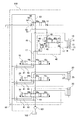
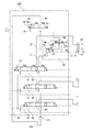
- FIG. 2 is a hydraulic circuit diagram of the fluid pressure control apparatus according to the embodiment of the present invention.
- FIG. 3 is a cross-sectional view of the neutral cut valve according to the embodiment of the present invention, showing a state where the neutral cut valve is in the communication position.
- FIG. 4 is a cross-sectional view of the neutral cut valve according to the embodiment of the present invention, showing a state in which the neutral cut valve is in the blocking position.
- FIG. 5 is a cross-sectional view of a neutral cut valve according to another embodiment of the present invention.
- FIG. 6 is a cross-sectional view of a neutral cut valve according to still another embodiment of the present invention.
- FIG. 7 is a hydraulic circuit diagram of the fluid pressure control device according to the embodiment of the present invention, showing a state in which the control valve is in the extended position.
- FIG. 8 is a hydraulic circuit diagram of the fluid pressure control device according to the embodiment of the present invention, showing a state where the control valve is in the neutral position.
- FIG. 9 is a hydraulic circuit diagram of the fluid pressure control apparatus according to the embodiment of the present invention, showing a state where the control valve is in the contracted position.
- valve device and a fluid pressure control device mounted on a hydraulic excavator will be described, but the present invention can also be applied to devices other than the hydraulic excavator.
- the working oil is used as the working fluid, but other fluids such as working water may be used as the working fluid.
- a hydraulic excavator 1 includes a crawler-type traveling unit 2, a swivel unit 3 that is pivotably provided at an upper portion of the travel unit 2, and an excavation unit 4 that is disposed at a front center portion of the swivel unit 3 .
- the traveling unit 2 has a pair of left and right crawlers 2a.
- the excavator 1 travels by driving a pair of left and right crawlers 2a by a travel motor (not shown).
- the turning unit 3 is turned around a vertical axis by a turning motor (not shown).
- the excavation part 4 has a boom 5, an arm 6, and a bucket 7.
- the boom 5 is supported by the turning unit 3 so as to be rotatable about a horizontal axis.
- the arm 6 is rotatably supported at the tip of the boom 5.
- the bucket 7 is rotatably supported at the tip of the arm 6 to excavate earth and sand.
- the excavating unit 4 includes a boom cylinder 10 that rotates the boom 5, an arm cylinder 20 that rotates the arm 6, and a bucket cylinder 30 that rotates the bucket 7.
- the expansion and contraction operations of the boom cylinder 10, the arm cylinder 20, and the bucket cylinder 30 are controlled using the fluid pressure control device 100 (see FIG. 2).
- the boom cylinder 10, the arm cylinder 20, and the bucket cylinder 30 are also simply referred to as “cylinders”, and the boom 5, the arm 6, and the bucket 7 are also referred to as “loads”.
- the fluid pressure control device 100 includes a supply passage 81, a discharge passage 82, and control valves 16, 26 and 36 provided in the supply passage 81.
- the supply passage 81 guides hydraulic oil discharged from the pump 101 as a fluid pressure supply unit to the cylinders 10, 20, and 30.
- the discharge passage 82 guides the hydraulic oil discharged from the cylinders 10, 20, and 30 to the tank 102 serving as a fluid reservoir.
- the control valves 16, 26, and 36 control the supply of hydraulic oil from the pump 101 to the cylinders 10, 20, and 30, respectively, and control the discharge of hydraulic oil from the cylinders 10, 20, and 30 to the tank 102.
- the boom cylinder 10 is a double-acting cylinder having a piston 14 that partitions the inside of a cylinder tube 11 into an anti-rod side chamber 12 and a rod side chamber 13.
- a rod 15 is attached to the piston 14.
- the first main passage 17 connects the anti-rod side chamber 12 and the control valve 16, and the second main passage 18 connects the rod side chamber 13 and the control valve 16.
- the first main passage 17 may be simply referred to as “main passage”.
- the control valve 16 is a 6-port 3-position switching valve having a neutral position 16a for stopping the operation of the boom cylinder 10, an extension position 16b for extending the boom cylinder 10, and a contraction position 16c for contracting the boom cylinder 10.
- the extension position 16b and the contraction position 16c are also referred to as “operation positions”.
- the arm cylinder 20 and the bucket cylinder 30 are double-acting cylinders, and the control valves 26 and 36 are 6-port 3-position switching valves. Since the structures of the cylinders 20 and 30 and the control valves 26 and 36 are the same as those of the boom cylinder 10 and the control valve 16, the description thereof is omitted here.
- the fluid pressure control device 100 includes a neutral passage 83 communicating with the upstream side of the control valves 16, 26, and 36 in the supply passage 81, and a neutral cut valve 50 as a valve device provided in the neutral passage 83.
- the neutral cut valve 50 is a two-port two-position switching valve having a communication position 50a that allows the flow of hydraulic oil in the neutral passage 83 and a blocking position 50b that blocks the flow of hydraulic oil in the neutral passage 83.
- the neutral passage 83 communicates the supply passage 81 and the discharge passage 82 through the control valves 16, 26 and 36.
- the neutral cut valve 50 is provided downstream of the control valves 16, 26, 36 in the neutral passage 83.
- the neutral cut valve 50 has a pilot chamber 51, and the communication position 50a and the cutoff position 50b are switched according to the supply of the pilot pressure to the pilot chamber 51.
- the neutral cut valve 50 maintains the communication position 50a by the biasing force of the spring 58 of the neutral cut valve 50.
- the neutral cut valve 50 is switched from the communication position 50a to the cutoff position 50b.
- the neutral cut valve 50 returns to the communication position 50a by the biasing force of the spring 58.
- Pilot pressure is supplied to the pilot chamber 51 when at least one of the control valves 16, 26, 36 is switched from the neutral positions 16a, 26a, 36a to the operating positions 16b, 16c, 26b, 26c, 36b, 36c. At this time, the neutral cut valve 50 is switched from the communication position 50a to the cutoff position 50b.
- the control oil 16 allows the flow of hydraulic oil in the supply passage 81 and the discharge passage 82, and blocks the flow of hydraulic oil in the neutral passage 83.
- the non-rod side chamber 12 communicates with the supply passage 81
- the rod side chamber 13 communicates with the discharge passage 82.
- the hydraulic oil discharged from the pump 101 is supplied to the anti-rod side chamber 12 and the hydraulic oil in the rod side chamber 13 is discharged to the tank 102.
- the boom cylinder 10 extends and the boom 5 (see FIG. 1) rises.
- the control oil 16 allows the flow of hydraulic oil in the supply passage 81 and the discharge passage 82, and blocks the flow of hydraulic oil in the neutral passage 83.
- the non-rod side chamber 12 communicates with the discharge passage 82 and the rod side chamber 13 communicates with the supply passage 81.
- the hydraulic oil discharged from the pump 101 is supplied to the rod side chamber 13 and the hydraulic oil in the non-rod side chamber 12 is discharged to the tank 102.
- the boom cylinder 10 contracts and the boom 5 (see FIG. 1) descends.
- the neutral cut valve 50 is suitable when the flow of hydraulic oil in the neutral passage 83 is not sufficiently blocked by the control valve 16 even when the control valve 16 is in the operating positions 16b and 16c.
- By blocking the flow of hydraulic oil in the neutral passage 83 using the neutral cut valve 50 when the control valve 16 is switched to the operating positions 16b and 16c and the boom cylinder 10 is expanded and contracted, a larger pressure is applied to the boom cylinder 10. Can act.
- the load acting on the boom cylinder 10 will be described.
- the control valve 16 When the control valve 16 is switched to the neutral position 16a with the boom 5 shown in FIG. 1 lifted, a force in a contracting direction acts on the boom cylinder 10 due to its own weight. That is, the load pressure acts on the non-rod side chamber 12.
- the non-rod side chamber 12 is also referred to as a “load side pressure chamber”.
- the fluid pressure control device 100 further includes a load holding unit 40 that is provided in the first main passage 17 and holds a load pressure acting on the anti-rod side chamber 12.
- a load holding unit 40 that is provided in the first main passage 17 and holds a load pressure acting on the anti-rod side chamber 12.
- the load holding unit 40 may be provided in the main passage 27 that connects the rod side chamber 23 corresponding to the load side pressure chamber of the arm cylinder 20 and the control valve 26. In this case, the load holding unit 40 can prevent the arm 6 (see FIG. 1) from descending.
- the structure of the load holding unit 40 will be described more specifically.
- the load holding unit 40 includes an operation check valve 41 provided in the first main passage 17, a switching valve 46 that switches the operation of the operation check valve 41, and a check valve passage 49 that is connected to the operation check valve 41 through the switching valve 46. And having.
- the operation check valve 41 includes a valve body 42 that opens and closes the first main passage 17, a back pressure chamber 43 provided facing the back surface of the valve body 42, and a spring 44 accommodated in the back pressure chamber 43. .
- the pressure in the back pressure chamber 43 and the urging force of the spring 44 act on the valve body 42 in the direction in which the valve body 42 is seated on the seat portion 45 (the valve closing direction).
- the pressure in the first main passage 17 acts on the valve body 42 in a direction (valve opening direction) in which the valve body 42 is separated from the seat portion 45. That is, the valve body 42 receives a load due to the pressure in the back pressure chamber 43 and the biasing force of the spring 44 in the valve closing direction, and receives a load due to the pressure in the first main passage 17 in the valve opening direction.
- the valve body 42 When the load acting on the valve body 42 due to the pressure in the first main passage 17 is smaller than the pressure acting on the valve body 42 due to the pressure in the back pressure chamber 43 and the biasing force of the spring 44, the valve body 42 is It sits on the seat part 45 and blocks the flow of hydraulic oil in the first main passage 17. When the load acting on the valve body 42 due to the pressure in the first main passage 17 is larger than the pressure acting on the valve body 42 due to the pressure in the back pressure chamber 43 and the biasing force of the spring 44, the valve body 42 is The hydraulic oil flows in the first main passage 17 away from the seat portion 45. Thus, the valve body 42 opens and closes according to the pressure in the back pressure chamber 43.
- the back pressure chamber 43 is connected to the anti-rod side chamber 12 through the switching valve 46 and is connected to the check valve passage 49 through the switching valve 46.
- the check valve passage 49 guides the hydraulic oil in the back pressure chamber 43 to the outside of the load holding unit 40.
- the switching valve 46 has a first position 46a and a second position 46b.
- the first position 46 a and the second position 46 b are switched according to the supply of pilot pressure to the pilot chamber 47 of the switching valve 46.
- the switching valve 46 When the pilot pressure is not supplied to the pilot chamber 47, the switching valve 46 maintains the first position 46a by the biasing force of the spring 48 of the switching valve 46. When the pilot pressure is supplied to the pilot chamber 47, the switching valve 46 is switched from the first position 46a to the second position 46b. When the supply of pilot pressure to the pilot chamber 47 is interrupted, the switching valve 46 returns to the first position 46 a by the urging force of the spring 48.
- the hydraulic oil is allowed to be supplied from the anti-rod side chamber 12 to the back pressure chamber 43 and the hydraulic oil is prevented from being discharged from the back pressure chamber 43 to the check valve passage 49. To do. Since the hydraulic oil in the back pressure chamber 43 is not discharged, the hydraulic oil supplied from the anti-rod side chamber 12 to the back pressure chamber 43 accumulates in the back pressure chamber 43, and the pressure in the anti-rod side chamber 12 passes through the first main passage 17. It acts on the pressure chamber 43. Therefore, the valve body 42 receives a load due to the urging force of the spring 44 and the pressure of the non-rod side chamber 12 in the valve closing direction.
- the valve body 42 receives a load due to the pressure of the anti-rod side chamber 12 in the valve opening direction. Since the load due to the urging force of the spring 44 and the pressure of the anti-rod side chamber 12 acts on the valve body 42 in the valve closing direction, the load only due to the pressure of the anti-rod side chamber 12 acts in the valve opening direction. The load in the valve opening direction acting on the valve element 42 is smaller than the load in the valve closing direction acting on the valve body 42.
- the valve body 42 Since the load in the valve opening direction is smaller than the load in the valve closing direction, the valve body 42 is seated on the seat portion 45. That is, the operation check valve 41 is closed and the flow of hydraulic oil in the first main passage 17 is shut off. Therefore, the load pressure acting on the anti-rod side chamber 12 is maintained, and the excavation part 4 (see FIG. 1) can be prevented from descending.
- the pressure of the hydraulic oil discharged from the pump 101 acts on the first main passage 17, so that the valve body 42 has a pump in addition to the load due to the pressure of the non-rod side chamber 12.
- a load due to the pressure of the hydraulic oil discharged from 101 is generated in the valve opening direction. Accordingly, the load in the valve opening direction acting on the valve body 42 is larger than the load in the valve closing direction acting on the valve body 42.
- the valve body 42 Since the load in the valve opening direction is larger than the load in the valve closing direction, the valve body 42 is separated from the seat portion 45. That is, the operation check valve 41 is opened, and the flow of hydraulic oil in the first main passage 17 is allowed. Therefore, the hydraulic oil discharged from the pump 101 is supplied to the anti-rod side chamber 12, and the excavation part 4 (refer FIG. 1) can be raised.
- the pilot pressure is supplied to the pilot chamber 47 when the control valve 16 is in the contracted position 16c. Therefore, the switching valve 46 is switched from the first position 46a to the second position 46b.
- the switching valve 46 When the switching valve 46 is in the second position 46b, the supply of hydraulic oil from the non-rod side chamber 12 to the back pressure chamber 43 is shut off, and discharge of the hydraulic oil from the back pressure chamber 43 to the check valve passage 49 is allowed. To do. Since the hydraulic oil in the back pressure chamber 43 is discharged from the load holding unit 40 without supplying the hydraulic oil to the back pressure chamber 43, the pressure of the hydraulic oil hardly acts on the back pressure chamber 43. Therefore, the valve body 42 receives a load only by the urging force of the spring 44 in the valve closing direction.
- the valve body 42 Since the load in the valve opening direction is larger than the load in the valve closing direction, the valve body 42 is separated from the seat portion 45. That is, the operation check valve 41 is opened, and the flow of hydraulic oil in the first main passage 17 is allowed. Therefore, the load pressure acting on the non-rod side chamber 12 is not maintained, and the excavation part 4 (see FIG. 1) can be lowered.
- the operation check valve 41 is closed when the control valve 16 is in the neutral position 16a, and is opened when the control valve 16 is in the operating positions 16b and 16c.
- FIGS. 3 is a cross-sectional view of the neutral cut valve 50 at the communication position 50a
- FIG. 4 is a cross-sectional view of the neutral cut valve 50 at the shut-off position 50b.
- the neutral cut valve 50 includes a valve body 52, a spool 53 as a valve body movably accommodated in the valve body 52, and a drain chamber wall 55 that partitions the drain chamber 54.
- the drain chamber wall 55 is provided in a cap 56 that is formed separately from the valve body 52.
- a sliding hole 57 is formed in the valve body 52, and the neutral passage 83 communicates with the sliding hole 57.
- the spool 53 is accommodated in the sliding hole 57, and the movement and the blocking of the hydraulic oil flow in the neutral passage 83 are switched by the movement of the spool 53.
- a drain chamber 54 is formed at one end of the sliding hole 57, and the spool 53 enters and exits the drain chamber 54 as the spool 53 moves.
- a spring 58 is accommodated in the drain chamber 54, and the spring 58 expands and contracts as the spool 53 moves.
- the pilot chamber 51 is formed on the other end side of the sliding hole 57.
- the spool 53 moves in the direction of entering the drain chamber 54 against the biasing force of the spring 58 by the pilot pressure, and blocks the flow of hydraulic oil in the neutral passage 83.
- the spool 53 moves in a direction in which the pilot chamber 51 is contracted by the biasing force of the spring 58 and allows the hydraulic oil to flow in the neutral passage 83.
- the neutral cut valve 50 includes a drain port 59 that allows the drain chamber 54 and the tank 102 to communicate with each other.
- the hydraulic oil in the drain chamber 54 is discharged from the drain port 59 to the tank 102 as drain.
- the drain port 59 is formed in the cap 56. Since the drain port 59 is formed in the cap 56 and the cap 56 is formed separately from the valve body 52, it is not necessary to change the valve body 52 when changing the size and dimensions of the drain port 59. Therefore, the versatility of the neutral cut valve 50 can be enhanced.
- the drain port 59 is formed on the drain chamber wall 55 so as to face the spool 53.
- the drain port 59 is formed coaxially with the spool 53. The movement of the spool 53 is restricted by contact with the drain chamber wall 55, more specifically, the peripheral edge of the drain port 59.
- the spool 53 has a communication path 60 that connects the drain port 59 and the drain chamber 54 when the movement of the spool 53 is restricted by the drain chamber wall 55. Therefore, even when the movement of the spool 53 is restricted by the drain chamber wall 55, the drain flow from the drain chamber 54 to the drain port 59 is not blocked. Therefore, the hydraulic oil in the drain chamber 54 can be discharged as drain from the drain port 59 to the tank 102 regardless of the position of the spool 53.
- the valve body 52 is formed with a drain passage 61 that communicates with the sliding hole 57 and guides the drain from the load holding unit 40 to the drain chamber 54.
- the hydraulic oil in the back pressure chamber 43 is drained as a drain passage 61, a drain chamber 54, and a drain port 59 by switching the switching valve 46 to the second position 46b when the control valve 16 is switched to the contracted position 16c. And is discharged to the tank 102.
- the neutral cut valve 50 is switched to the cutoff position 50b, and the movement of the spool 53 is restricted by the drain chamber wall 55. Since the spool 53 has the communication passage 60, the drain flow from the drain chamber 54 to the drain port 59 is not blocked even when the movement of the spool 53 is restricted by the drain chamber wall 55. Therefore, regardless of the position of the spool 53, the hydraulic oil in the back pressure chamber 43 can be discharged from the drain port 59 as a drain.
- the drain passage 61 is not limited to the form formed in the valve body 52.
- the drain passage 61 may be a conduit that directly connects the back pressure chamber 43 and the drain chamber 54 of the load holding unit 40.
- the working oil in the back pressure chamber 43 of the load holding unit 40 is discharged from the drain port 59 as a drain.
- the pressure in the neutral passage 83 may be larger than the pressure in the tank 102 depending on the operation state of the pump 101.
- the pressure in the back pressure chamber 43 is changed when the switching valve 46 is switched to the second position 46b.
- the operation check valve 41 may not be opened due to insufficient lowering.
- the hydraulic oil in the non-rod side chamber 12 does not flow to the control valve 16, and the boom 5 (see FIG. 1) cannot be lowered.
- the hydraulic oil in the back pressure chamber 43 is discharged as drain through a passage different from the neutral passage 83, and therefore the pressure in the back pressure chamber 43 is changed when the switching valve 46 is switched to the second position 46b. It goes down enough. Therefore, the operation check valve 41 can be opened more reliably, and the hydraulic oil in the anti-rod side chamber 12 can be flowed to the control valve 16 to lower the boom 5 (see FIG. 1).
- drain passage 61 is connected to the back pressure chamber 43, it is not necessary to provide a drain port for discharging the drain of the load holding unit 40 separately from the drain port 59 of the neutral cut valve 50. Therefore, the number of drain ports of the fluid pressure control device 100 can be reduced.
- the communication path 60 includes a first hole 60 a extending from the end surface of the spool 53 along the axial direction of the spool 53, and a first hole extending along the radial direction from the side surface of the spool 53.
- a second hole 60b communicating with the hole 60a. Since it is easy to form a hole extending in the axial direction such as the first hole 60a and a hole extending in the radial direction such as the second hole 60b in the spool 53, the first hole 60a and the second hole 60b are included.
- the communication path 60 is easily formed. Therefore, the neutral cut valve 50 can be easily manufactured.
- the communication path 60 is not limited to this form.
- the communication path 60 may be a groove 60 c (notch) formed on the side surface of the spool 53 and opening at the end surface of the spool 53. Since it is easy to form the groove 60c opening in the end surface of the spool 53 on the side surface of the spool 53, the communication path 60 including such a groove 60c is easily formed. Therefore, the neutral cut valve 50 can be easily manufactured.
- the communication path 60 may be a groove 60 d (notch) that is formed on the periphery of the drain port 59 and opens on the inner surface of the drain port 59. That is, the communication path 60 may be formed in the drain chamber wall 55.
- the groove 60d is provided on the side of the drain chamber wall 55 of the cap 56 facing the drain chamber 54, it is not necessary to prepare the spool 53 (see FIGS. 3 to 5) having the communication path 60 when replacing the spool 53. . Therefore, the versatility of the neutral cut valve 50 can be enhanced.
- valve device to which the present embodiment is applicable is not limited to the neutral cut valve 50. This embodiment is applicable to a valve device having a drain port.
- the drain passage 61 may be connected to a valve device different from the load holding unit 40. That is, the drain passage 61 may be formed so as to guide drain from another valve device different from the neutral cut valve 50 to the drain chamber 54.
- the drain passage 61 may be configured to guide drain from a plurality of other valve devices to the drain chamber 54.
- control valve 16 is switched from the neutral position 16a to the extended position 16b.
- pilot pressure is supplied to the pilot chamber 51, and the neutral cut valve 50 is switched to the cutoff position 50b.
- the switching valve 46 maintains the first position 46a.
- the control valve 16 communicates the supply passage 81 and the first main passage 17 and communicates the discharge passage 82 and the second main passage 18. Accordingly, the hydraulic oil discharged from the pump 101 is sent to the operation check valve 41 through the first main passage 17.
- the switching valve 46 Since the switching valve 46 is in the first position 46a, the flow of hydraulic oil from the back pressure chamber 43 to the check valve passage 49 is blocked, and the flow of hydraulic oil from the non-rod side chamber 12 to the back pressure chamber 43 is allowed. . Therefore, the valve body 42 receives a load due to the urging force of the spring 44 and the pressure of the non-rod side chamber 12 in the valve closing direction.
- the valve element 42 receives a load due to the pressure of the hydraulic oil discharged from the pump 101 in addition to a load due to the pressure of the anti-rod side chamber 12 in the valve opening direction.
- the load due to the pressure of the anti-rod side chamber 12 and the pressure of the hydraulic oil discharged from the pump 101 is larger than the load due to the urging force of the spring 44 and the pressure of the anti-rod side chamber 12. Therefore, the valve body 42 is separated from the seat portion 45 and the operation check valve 41 is opened to allow the flow of hydraulic oil in the first main passage 17.
- the hydraulic oil discharged from the pump 101 is sent to the non-rod side chamber 12, and the hydraulic oil in the rod side chamber 13 is sent to the discharge passage 82, so that the boom cylinder 10 extends.
- the excavation part 4 (refer FIG. 1) raises.
- the neutral cut valve 50 Since the neutral cut valve 50 is in the cutoff position 50b, the hydraulic oil discharged from the pump 101 does not flow through the neutral passage 83 more reliably. Therefore, the pressure of the hydraulic oil discharged from the pump 101 is more efficiently transmitted to the anti-rod side chamber 12, and a large force can be applied to the boom cylinder 10.
- control valve 16 is switched from the extended position 16b to the neutral position 16a. It is assumed that the control valves 26 and 36 are in the neutral positions 26a and 36a.
- the control valve 16 allows the flow of hydraulic oil in the neutral passage 83 and blocks the flow of hydraulic oil in the supply passage 81. Therefore, the hydraulic oil discharged from the pump 101 is not sent to the operation check valve 41. Since the control valves 26 and 36 are in the neutral positions 26 a and 36 a and the neutral cut valve 50 is in the communication position 50 a, the hydraulic oil discharged from the pump 101 returns to the tank 102 through the neutral passage 83.
- the switching valve 46 Since the switching valve 46 is in the first position 46a, the discharge of hydraulic oil from the back pressure chamber 43 to the check valve passage 49 is blocked, and the flow of hydraulic oil from the non-rod side chamber 12 to the back pressure chamber 43 is allowed. . Therefore, the valve body 42 receives a load due to the urging force of the spring 44 and the pressure of the non-rod side chamber 12 in the valve closing direction.
- the valve body 42 receives the load only due to the load due to the pressure of the non-rod side chamber 12 in the valve opening direction.
- the load due to the pressure of the anti-rod side chamber 12 is smaller than the load due to the biasing force of the spring 44 and the pressure of the anti-rod side chamber 12. Accordingly, the valve body 42 is seated on the seat portion 45, the operation check valve 41 is closed, and the flow of hydraulic oil in the first main passage 17 is blocked. The load pressure acting on the anti-rod side chamber 12 is maintained, and the excavation unit 4 (see FIG. 1) can be prevented from descending.
- the pilot pressure is supplied to the pilot chamber 47 and the pilot pressure is supplied to the pilot chamber 51 in conjunction with the switching of the control valve 16 from the neutral position 16a to the contracted position 16c. Therefore, the switching valve 46 is switched to the second position 46b, and the neutral cut valve 50 is switched to the cutoff position 50b.
- the control valve 16 communicates the supply passage 81 and the second main passage 18 and communicates the discharge passage 82 and the first main passage 17. Therefore, the hydraulic oil discharged from the pump 101 is sent to the rod side chamber 13 through the second main passage 18.
- the switching valve 46 Since the switching valve 46 is in the second position 46b, the hydraulic oil is allowed to be discharged from the back pressure chamber 43 to the check valve passage 49, and the supply of hydraulic oil from the non-rod side chamber 12 to the back pressure chamber 43 is shut off. . Since the hydraulic oil in the back pressure chamber 43 is discharged to the check valve passage 49 without supplying the hydraulic oil to the back pressure chamber 43, the pressure of the hydraulic oil hardly acts on the back pressure chamber 43. Therefore, the valve body 42 receives a load only by the urging force of the spring 44 in the valve closing direction.
- the pressure of the hydraulic oil discharged from the pump 101 acts on the rod side chamber 13.
- the pressure in the rod side chamber 13 acts on the valve body 42 in the valve opening direction through the anti-rod side chamber 12 and the first main passage 17. Therefore, the valve body 42 receives a load due to the load pressure in the valve opening direction.
- the load pressure is larger than the load due to the urging force of the spring 44. Therefore, the valve body 42 is separated from the seat portion 45, and the operation check valve 41 is opened to allow the hydraulic oil to flow in the first main passage 17.
- the hydraulic oil discharged from the pump 101 is sent to the rod side chamber 13, and the hydraulic oil in the non-rod side chamber 12 is sent to the discharge passage 82, so that the boom cylinder 10 contracts. As a result, the excavation part 4 (refer FIG. 1) descends.
- the neutral cut valve 50 Since the neutral cut valve 50 is in the cutoff position 50b, the hydraulic oil discharged from the pump 101 does not flow through the neutral passage 83 more reliably. Therefore, the pressure of the hydraulic oil discharged from the pump 101 is more efficiently transmitted to the rod side chamber 13, and a large force can be applied to the boom cylinder 10.
- the communication passage 60 communicates the drain chamber 54 and the drain port 59, even when the movement of the spool 53 is restricted by the drain chamber wall 55, the drain of the drain from the back pressure chamber 43 to the drain port 59 can be performed.
- the flow is not interrupted. Therefore, if the switching valve 46 is in the second position 46b, the hydraulic oil in the back pressure chamber 43 can be discharged from the drain port 59 as a drain. As a result, the operation check valve 41 can be opened, and the excavation unit 4 (see FIG. 1) can be lowered.
- the spool 53 Since the spool 53 has the communication path 60, the flow of drain from the drain chamber 54 to the drain port 59 is not blocked even when the movement of the spool 53 is restricted by the drain chamber wall 55. Therefore, regardless of the position of the spool 53, the drain of the load holding unit 40 can be discharged from the drain port 59.
- the drain port 59 is formed on the cap 56 and the cap 56 is formed separately from the valve body 52, it is not necessary to change the valve body 52 when changing the size and dimensions of the drain port 59. Therefore, the versatility of the neutral cut valve 50 can be enhanced.
- the operation check valve 41 can be opened more reliably, and the hydraulic oil in the anti-rod side chamber 12 can be flowed to the control valve 16 to lower the boom 5 (see FIG. 1).
- drain passage 61 is connected to the back pressure chamber 43, it is not necessary to provide a drain port for discharging the drain of the load holding unit 40 separately from the drain port 59 of the neutral cut valve 50. Therefore, the number of drain ports of the fluid pressure control device 100 can be reduced.
- the switching valve 46 shuts off the supply of hydraulic oil from the anti-rod side chamber 12 to the back pressure chamber 43 when allowing the hydraulic oil to be discharged from the back pressure chamber 43 to the drain chamber 54. Oil does not flow to the drain chamber 54. Therefore, a large amount of hydraulic oil can be prevented from being discharged from the drain port 59.
- the switching valve 46 allows the supply of hydraulic oil from the anti-rod side chamber 12 to the back pressure chamber 43 when shutting off the discharge of hydraulic oil from the back pressure chamber 43 to the drain chamber 54.
- the hydraulic oil accumulates in the back pressure chamber 43, and the pressure in the anti-rod side chamber 12 acts on the back pressure chamber 43. Therefore, the flow of hydraulic oil from the non-rod side chamber 12 to the control valve 16 by the operation check valve 41 can be more reliably blocked.
- the neutral cut valve 50 includes a spool 53 that is movably accommodated in the valve body 52, a drain chamber wall 55 that defines a drain chamber 54 in which the spool 53 moves in and out as the spool 53 moves, A drain port 59 that is formed in the drain chamber wall 55 so as to face the spool 53 and communicates the drain chamber 54 and the tank 102, and a drain passage 61 that guides the drain from the load holding unit 40 to the drain chamber 54.
- At least one of the chamber wall 55 and the spool 53 has a communication path 60 that allows the drain port 59 and the drain chamber 54 to communicate with each other when the movement of the spool 53 is restricted by the drain chamber wall 55.
- the communication path 60 includes a first hole 60 a provided in the spool 53 and extending in the axial direction of the spool 53, and a second hole 60 b provided in the spool 53 and extending in the radial direction of the spool 53.
- the first hole 60a and the second hole 60b communicate with each other.
- the first hole 60 a extends in the axial direction of the spool 53
- the second hole 60 b extends in the radial direction of the spool 53. Since it is easy to form a hole extending in the axial direction such as the first hole 60a and a hole extending in the radial direction such as the second hole 60b in the spool 53, the first hole 60a and the second hole 60b are included.
- the communication path 60 is easily formed. Therefore, the neutral cut valve 50 can be easily manufactured.
- the communication path 60 includes a groove 60 c provided on the side surface of the spool 53 and opening on the end surface of the spool 53.
- the groove 60 c is provided on the side surface of the spool 53 and opens to the end surface of the spool 53. Since it is easy to form such a groove 60c in the spool 53, the communication path 60 including the groove 60c is easily formed. Therefore, the neutral cut valve 50 can be easily manufactured.
- the neutral cut valve 50 further includes a cap 56 that is formed separately from the valve body 52 and provided with a drain chamber wall 55, and a drain port 59 is formed in the cap 56.
- the drain port 59 is formed on the cap 56 and the cap 56 is formed separately from the valve body 52, it is necessary to change the valve body 52 when changing the size and dimensions of the drain port 59. There is no. Therefore, the versatility of the neutral cut valve 50 can be enhanced.
- the communication path 60 includes a groove 60 d provided on the side of the drain chamber wall 55 of the cap 56 facing the drain chamber 54.
- the fluid pressure control device 100 that controls the expansion and contraction operation of the cylinder 10 that drives the boom 5 includes the control valve 16 that controls the supply of hydraulic oil from the pump 101 to the boom cylinder 10, and the control valve 16. Is located at a neutral position 16a that blocks the flow of hydraulic oil to the boom cylinder 10, and a first main passage 17 that connects the anti-rod side chamber 12 of the boom cylinder 10 to which the load pressure by the load 5 acts and the control valve 16 is connected.
- a load holding unit 40 provided in the first main passage 17, a neutral passage 83 for returning the hydraulic oil discharged from the pump 101 to the tank 102 when the control valve 16 is in the neutral position 16a, and a neutral passage 83.
- a neutral cut valve 50 that switches between allowing and shutting off the flow of the hydraulic oil in the neutral passage 83, and the load holding unit 40 extends from the control valve 16 to the anti-rod.
- the drain passage 61 is connected to the back pressure chamber 43.
- the drain passage 61 is connected to the back pressure chamber 43, the drain of the load holding unit 40 is guided to the drain chamber 54 through the drain passage 61 and discharged from the drain port 59 of the neutral cut valve 50. Therefore, the number of drain ports of the fluid pressure control device 100 can be reduced.
- the operation check valve 41 can be opened more reliably when the hydraulic oil in the non-rod side chamber 12 flows to the control valve 16.
- the load holding unit 40 controls the supply of hydraulic oil from the anti-rod side chamber 12 to the back pressure chamber 43, and the back pressure chamber 43 to the drain chamber 54.
- the switching valve 46 further controls the discharge of the hydraulic oil, and the switching valve 46 operates from the anti-rod side chamber 12 to the back pressure chamber 43 when blocking the discharge of the hydraulic oil from the back pressure chamber 43 to the drain chamber 54.
- the first position 46a that allows the supply of oil
- the second position that blocks the supply of hydraulic oil from the non-rod side chamber 12 to the back pressure chamber 43 when permitting the discharge of hydraulic oil from the back pressure chamber 43 to the drain chamber 54.
- a position 46b is a position 46b.
- the switching valve 46 allows the hydraulic oil to be supplied from the anti-rod side chamber 12 to the back pressure chamber 43 when blocking the discharge of the hydraulic oil from the back pressure chamber 43 to the drain chamber 54.
- 12 hydraulic oil accumulates in the back pressure chamber 43, and the pressure in the non-rod side chamber 12 acts on the back pressure chamber 43. Therefore, the flow of hydraulic oil from the non-rod side chamber 12 to the control valve 16 by the operation check valve 41 can be more reliably blocked.
- the switching valve 46 shuts off the supply of hydraulic oil from the anti-rod side chamber 12 to the back pressure chamber 43 when allowing the hydraulic oil to be discharged from the back pressure chamber 43 to the drain chamber 54.
- the hydraulic oil does not flow into the drain chamber 54. Therefore, a large amount of hydraulic oil can be prevented from being discharged from the drain port 59.
Landscapes
- Engineering & Computer Science (AREA)
- General Engineering & Computer Science (AREA)
- Mechanical Engineering (AREA)
- Physics & Mathematics (AREA)
- Fluid Mechanics (AREA)
- Civil Engineering (AREA)
- Mining & Mineral Resources (AREA)
- Structural Engineering (AREA)
- Chemical & Material Sciences (AREA)
- Analytical Chemistry (AREA)
- Fluid-Pressure Circuits (AREA)
- Valve Housings (AREA)
- Lift Valve (AREA)
- Sliding Valves (AREA)
- Fluid-Driven Valves (AREA)
Abstract
Description
Claims (7)
- バルブ装置であって、
バルブボディ内に移動自在に収容された弁体と、
前記弁体の移動に伴って前記弁体が出入りするドレン室を区画するドレン室壁と、
前記ドレン室壁に前記弁体と対向して形成され前記ドレン室と流体貯留部とを連通するドレンポートと、
他のバルブ装置からのドレンを前記ドレン室に導くドレン通路と、を備え、
前記ドレン室壁及び前記弁体の少なくとも一方は、前記弁体の移動が前記ドレン室壁によって制限されたときに前記ドレンポートと前記ドレン室とを連通する連通路を有する、バルブ装置。 - 請求項1に記載のバルブ装置であって、
前記連通路は、前記弁体に設けられ前記弁体の軸方向に延びる第1穴と、前記弁体に設けられ前記弁体の径方向に延びる第2穴と、を含み、
前記第1穴と前記第2穴とが連通する、バルブ装置。 - 請求項1に記載のバルブ装置であって、
前記連通路は、前記弁体の側面に設けられ前記弁体の端面に開口する切り欠きを含む、バルブ装置。 - 請求項1に記載のバルブ装置であって、
前記バルブボディとは別体として形成され前記ドレン室壁が設けられたキャップをさらに備え、
前記キャップに前記ドレンポートが形成される、バルブ装置。 - 請求項4に記載のバルブ装置であって、
前記連通路は、前記キャップの前記ドレン室壁における前記ドレン室に臨む側に設けられる切り欠きを含む、バルブ装置。 - 負荷を駆動するシリンダの伸縮動作を制御する流体圧制御装置であって、
流体圧供給部から前記シリンダへの作動流体の供給を制御する制御弁と、
前記制御弁が前記シリンダへの作動流体の流れを遮断する中立位置にある場合に前記負荷による負荷圧が作用する前記シリンダの負荷側圧力室と前記制御弁とを接続するメイン通路と、
前記メイン通路に設けられる請求項1に記載の他のバルブ装置としての負荷保持部と、
前記制御弁が前記中立位置にあるときに前記流体圧供給部から吐出された作動流体を前記流体貯留部へ戻す中立通路と、
前記中立通路に設けられ前記中立通路における作動流体の流れの許容及び遮断を切り換える請求項1に記載のバルブ装置としての中立カット弁と、を備え、
前記負荷保持部は、前記制御弁から前記負荷側圧力室への作動流体を許容する一方、背圧室内の作動流体がドレンとして排出されたときに前記負荷側圧力室から前記制御弁への作動流体の流れを許容するオペレートチェック弁を有し、
前記ドレン通路は前記背圧室に接続される、流体圧制御装置。 - 請求項6に記載の流体圧制御装置であって、
前記負荷保持部は、前記負荷側圧力室から前記背圧室への作動流体の供給を制御するとともに、前記背圧室から前記ドレン室への作動流体の排出を制御する切換弁をさらに有し、
前記切換弁は、前記背圧室から前記ドレン室への作動流体の排出を遮断するときには前記負荷側圧力室から前記背圧室への作動流体の供給を許容する第1位置と、前記背圧室から前記ドレン室への作動流体の排出を許容するときには前記負荷側圧力室から前記背圧室への作動流体の供給を遮断する第2位置とを有する、流体圧制御装置。
Priority Applications (3)
| Application Number | Priority Date | Filing Date | Title |
|---|---|---|---|
| US15/566,259 US10359057B2 (en) | 2015-04-15 | 2016-03-14 | Valve device and fluid pressure control device |
| CN201680021358.XA CN107429851B (zh) | 2015-04-15 | 2016-03-14 | 阀装置和流体压控制装置 |
| KR1020177032612A KR102021219B1 (ko) | 2015-04-15 | 2016-03-14 | 밸브 장치 및 유체압 제어 장치 |
Applications Claiming Priority (2)
| Application Number | Priority Date | Filing Date | Title |
|---|---|---|---|
| JP2015-083463 | 2015-04-15 | ||
| JP2015083463A JP6012806B1 (ja) | 2015-04-15 | 2015-04-15 | バルブ装置及び流体圧制御装置 |
Publications (1)
| Publication Number | Publication Date |
|---|---|
| WO2016167065A1 true WO2016167065A1 (ja) | 2016-10-20 |
Family
ID=57126128
Family Applications (1)
| Application Number | Title | Priority Date | Filing Date |
|---|---|---|---|
| PCT/JP2016/057998 Ceased WO2016167065A1 (ja) | 2015-04-15 | 2016-03-14 | バルブ装置及び流体圧制御装置 |
Country Status (5)
| Country | Link |
|---|---|
| US (1) | US10359057B2 (ja) |
| JP (1) | JP6012806B1 (ja) |
| KR (1) | KR102021219B1 (ja) |
| CN (1) | CN107429851B (ja) |
| WO (1) | WO2016167065A1 (ja) |
Cited By (1)
| Publication number | Priority date | Publication date | Assignee | Title |
|---|---|---|---|---|
| US11753801B2 (en) * | 2018-12-13 | 2023-09-12 | Kawasaki Jukogyo Kabushiki Kaisha | Hydraulic drive system |
Families Citing this family (2)
| Publication number | Priority date | Publication date | Assignee | Title |
|---|---|---|---|---|
| JP6012806B1 (ja) * | 2015-04-15 | 2016-10-25 | Kyb株式会社 | バルブ装置及び流体圧制御装置 |
| CN111237275B (zh) * | 2020-01-10 | 2024-05-17 | 武汉科技大学 | 一种高压滑阀型单向阀 |
Citations (2)
| Publication number | Priority date | Publication date | Assignee | Title |
|---|---|---|---|---|
| JP2000035008A (ja) * | 1998-07-17 | 2000-02-02 | Sumitomo Electric Ind Ltd | 液圧制御装置 |
| JP2013204603A (ja) * | 2012-03-27 | 2013-10-07 | Kyb Co Ltd | 流体圧制御装置 |
Family Cites Families (40)
| Publication number | Priority date | Publication date | Assignee | Title |
|---|---|---|---|---|
| US1156011A (en) * | 1913-11-20 | 1915-10-05 | Dalton Ingersoll Mfg Company | Drinking-fountain. |
| US2410422A (en) * | 1943-12-14 | 1946-11-05 | George A Breene | Glassmaking machinery |
| US2979080A (en) * | 1959-01-29 | 1961-04-11 | Westinghouse Air Brake Co | Valve device with annular resilient valving elements |
| US3117591A (en) * | 1960-08-29 | 1964-01-14 | Penn Controls | Delayed step opening gas regulator |
| US3112763A (en) * | 1962-04-12 | 1963-12-03 | Hydraulic Unit Specialities Co | Combined high pressure relief and void control valve |
| US3563273A (en) * | 1968-10-28 | 1971-02-16 | Carl R Mills | Actuator valve |
| GB1302742A (ja) * | 1969-04-07 | 1973-01-10 | ||
| US3856041A (en) * | 1973-11-28 | 1974-12-24 | Caterpillar Tractor Co | Combination relief and make-up valve |
| DE2702399A1 (de) * | 1977-01-21 | 1978-07-27 | Teves Gmbh Alfred | Vorrichtung fuer bremssysteme mit einer druckregeleinrichtung zur blockierregelung |
| JPS5410430A (en) * | 1977-06-24 | 1979-01-26 | Caterpillar Mitsubishi Ltd | Compound safety valve having functions of relief valve and make up valve |
| JPS595259Y2 (ja) * | 1979-01-12 | 1984-02-16 | 東芝機械株式会社 | リリ−フバルブ兼用メイクアツプバルブ |
| US4381099A (en) * | 1981-04-28 | 1983-04-26 | The Penmont Company | Faucet for frozen carbonated beverage machine |
| JPS6124886A (ja) | 1984-07-14 | 1986-02-03 | Hitachi Constr Mach Co Ltd | パイロツト操作回路の暖気装置 |
| JPS6346721Y2 (ja) * | 1984-11-12 | 1988-12-05 | ||
| US4844119A (en) * | 1988-11-21 | 1989-07-04 | Allied-Signal Inc. | Integrated three-way and isolation solenoid valve |
| CH683803A5 (fr) * | 1990-05-18 | 1994-05-13 | Hobac S A | Vanne régulatrice automatique. |
| DE59103692D1 (de) * | 1991-01-25 | 1995-01-12 | Asea Brown Boveri | Zuschaltventil und hydraulisches Sicherheits- und Kraftölsystem, in welchem das Zuschaltventil verwendet wird. |
| DE4133536C2 (de) * | 1991-10-10 | 1995-11-30 | Hydraulik Ring Gmbh | Hydraulikmagnetventil |
| US5261447A (en) * | 1992-11-25 | 1993-11-16 | Fred Knapp Engraving Co., Inc. | Pneumatic regulating valve |
| KR100348128B1 (ko) * | 1994-09-30 | 2002-11-22 | 볼보 컨스트럭션 이키프먼트 홀딩 스웨덴 에이비 | 가변우선기능을갖는콘트롤밸브 |
| US5722454A (en) * | 1996-03-12 | 1998-03-03 | Q-Fuse Llc | Fluid flow fuse |
| US6257268B1 (en) * | 1999-12-01 | 2001-07-10 | Gilmore Valve Company | Pressure biased shuttle valve |
| JP4128482B2 (ja) * | 2002-04-30 | 2008-07-30 | 東芝機械株式会社 | 油圧制御システム |
| DE10342478B3 (de) * | 2003-09-15 | 2004-12-16 | Sauer-Danfoss (Neumünster) GmbH & Co OHG | Ventilanordnung zur Steuerung von Hydraulikflüssigkeit in einer Axialkolbenmaschine |
| JP4199644B2 (ja) | 2003-11-07 | 2008-12-17 | 株式会社不二越 | ノッチによる流体力を低減する構造のスプール弁 |
| US7357153B2 (en) * | 2003-11-25 | 2008-04-15 | Hamai Industries Limited | Pressure-reducing valve for high-pressure gas cylinders |
| DE102004033022A1 (de) * | 2004-07-08 | 2006-02-02 | Ina-Schaeffler Kg | Rückschlagventil |
| JP4081487B2 (ja) * | 2004-12-28 | 2008-04-23 | 東芝機械株式会社 | 油圧制御弁 |
| US7240604B2 (en) * | 2005-07-29 | 2007-07-10 | Caterpillar Inc | Electro-hydraulic metering valve with integral flow control |
| US7658405B2 (en) * | 2006-07-31 | 2010-02-09 | Delphi Technologies, Inc. | Apparatus and method for providing extended inflator output |
| JP4782711B2 (ja) * | 2007-02-21 | 2011-09-28 | 日立建機株式会社 | 方向制御弁装置およびこの方向制御弁装置を複数備えた方向制御弁装置ブロック |
| JP2008309318A (ja) * | 2007-06-18 | 2008-12-25 | Kyb Engineering & Service Co Ltd | スローリターン装置 |
| WO2009091683A1 (en) * | 2008-01-17 | 2009-07-23 | Becton, Dickinson And Company | Valve for mixing of substances |
| US20100181519A1 (en) * | 2009-01-22 | 2010-07-22 | Renzhong Li | Automatic switch valve |
| US9067038B2 (en) * | 2009-08-31 | 2015-06-30 | William A. Leffel | Valve system for use with a flexible gas supply tube extending to a patient |
| DE102010055747B3 (de) * | 2010-12-22 | 2012-07-05 | Magna Steyr Fahrzeugtechnik Ag & Co Kg | Druckminderer |
| JP5840987B2 (ja) * | 2012-03-15 | 2016-01-06 | Kyb株式会社 | 制御バルブ |
| EP2728163B1 (en) * | 2012-10-30 | 2016-08-17 | Delphi International Operations Luxembourg S.à r.l. | Valve arrangement |
| JP6007746B2 (ja) * | 2012-11-20 | 2016-10-12 | アイシン精機株式会社 | 作動油供給装置 |
| JP6012806B1 (ja) * | 2015-04-15 | 2016-10-25 | Kyb株式会社 | バルブ装置及び流体圧制御装置 |
-
2015
- 2015-04-15 JP JP2015083463A patent/JP6012806B1/ja active Active
-
2016
- 2016-03-14 CN CN201680021358.XA patent/CN107429851B/zh active Active
- 2016-03-14 KR KR1020177032612A patent/KR102021219B1/ko active Active
- 2016-03-14 WO PCT/JP2016/057998 patent/WO2016167065A1/ja not_active Ceased
- 2016-03-14 US US15/566,259 patent/US10359057B2/en active Active
Patent Citations (2)
| Publication number | Priority date | Publication date | Assignee | Title |
|---|---|---|---|---|
| JP2000035008A (ja) * | 1998-07-17 | 2000-02-02 | Sumitomo Electric Ind Ltd | 液圧制御装置 |
| JP2013204603A (ja) * | 2012-03-27 | 2013-10-07 | Kyb Co Ltd | 流体圧制御装置 |
Cited By (1)
| Publication number | Priority date | Publication date | Assignee | Title |
|---|---|---|---|---|
| US11753801B2 (en) * | 2018-12-13 | 2023-09-12 | Kawasaki Jukogyo Kabushiki Kaisha | Hydraulic drive system |
Also Published As
| Publication number | Publication date |
|---|---|
| US20180106277A1 (en) | 2018-04-19 |
| CN107429851A (zh) | 2017-12-01 |
| KR102021219B1 (ko) | 2019-09-11 |
| JP2016205420A (ja) | 2016-12-08 |
| KR20170136604A (ko) | 2017-12-11 |
| US10359057B2 (en) | 2019-07-23 |
| JP6012806B1 (ja) | 2016-10-25 |
| CN107429851B (zh) | 2019-05-07 |
Similar Documents
| Publication | Publication Date | Title |
|---|---|---|
| JP6001846B2 (ja) | 油圧制御装置、及びそれを備える建設機械 | |
| JP6647826B2 (ja) | 方向切換弁及び油圧システム | |
| CN101270766B (zh) | 在重型设备行进过程中防止铲斗从铲斗支座分离的液压回路 | |
| KR101718835B1 (ko) | 건설기계의 유압제어밸브 | |
| WO2019220872A1 (ja) | 作業機械の油圧駆動装置 | |
| KR20190030160A (ko) | 유압 회로 | |
| JP6012806B1 (ja) | バルブ装置及び流体圧制御装置 | |
| KR101831494B1 (ko) | 방향 전환 밸브 | |
| JP2006329341A (ja) | 作業機械の油圧制御装置 | |
| CN112867828B (zh) | 防漂移阀装置,刀片装置和工作机械 | |
| JP7530312B2 (ja) | マルチ制御弁 | |
| JP6307292B2 (ja) | 作業機の制御システム | |
| CN104929997A (zh) | 工程机械用液压回路 | |
| EP3101282B1 (en) | Hydraulic pressure control device for a construction machine | |
| JP4763365B2 (ja) | ローダ用油圧制御装置 | |
| JP2014148994A (ja) | 作業機械の油圧制御装置 | |
| JP4859786B2 (ja) | 制御装置 | |
| JP6755814B2 (ja) | 方向切換弁 | |
| WO2020044701A1 (ja) | 流体圧制御装置 | |
| JP6706170B2 (ja) | 流体圧制御装置 | |
| JP2018168916A (ja) | 建設機械の油圧制御装置 | |
| JP2018053474A (ja) | ブームを備えた建設機械の油圧駆動装置 | |
| KR101779194B1 (ko) | 건설장비의 작동유 제어장치 | |
| JP2006349165A (ja) | ホールディングバルブを持つ圧力補償型油圧回路 | |
| JP3805669B2 (ja) | 油圧機械の配管破断制御弁装置及びオフセット式油圧ショベルのオフセットシリンダ装置 |
Legal Events
| Date | Code | Title | Description |
|---|---|---|---|
| 121 | Ep: the epo has been informed by wipo that ep was designated in this application |
Ref document number: 16779857 Country of ref document: EP Kind code of ref document: A1 |
|
| WWE | Wipo information: entry into national phase |
Ref document number: 15566259 Country of ref document: US |
|
| NENP | Non-entry into the national phase |
Ref country code: DE |
|
| ENP | Entry into the national phase |
Ref document number: 20177032612 Country of ref document: KR Kind code of ref document: A |
|
| 122 | Ep: pct application non-entry in european phase |
Ref document number: 16779857 Country of ref document: EP Kind code of ref document: A1 |