WO2016166816A1 - 走査型プローブ顕微鏡 - Google Patents
走査型プローブ顕微鏡 Download PDFInfo
- Publication number
- WO2016166816A1 WO2016166816A1 PCT/JP2015/061494 JP2015061494W WO2016166816A1 WO 2016166816 A1 WO2016166816 A1 WO 2016166816A1 JP 2015061494 W JP2015061494 W JP 2015061494W WO 2016166816 A1 WO2016166816 A1 WO 2016166816A1
- Authority
- WO
- WIPO (PCT)
- Prior art keywords
- probe
- relative
- sample
- control unit
- relative speed
- Prior art date
- Legal status (The legal status is an assumption and is not a legal conclusion. Google has not performed a legal analysis and makes no representation as to the accuracy of the status listed.)
- Ceased
Links
Images





Classifications
-
- G—PHYSICS
- G01—MEASURING; TESTING
- G01Q—SCANNING-PROBE TECHNIQUES OR APPARATUS; APPLICATIONS OF SCANNING-PROBE TECHNIQUES, e.g. SCANNING PROBE MICROSCOPY [SPM]
- G01Q10/00—Scanning or positioning arrangements, i.e. arrangements for actively controlling the movement or position of the probe
- G01Q10/04—Fine scanning or positioning
- G01Q10/06—Circuits or algorithms therefor
-
- G—PHYSICS
- G01—MEASURING; TESTING
- G01Q—SCANNING-PROBE TECHNIQUES OR APPARATUS; APPLICATIONS OF SCANNING-PROBE TECHNIQUES, e.g. SCANNING PROBE MICROSCOPY [SPM]
- G01Q10/00—Scanning or positioning arrangements, i.e. arrangements for actively controlling the movement or position of the probe
- G01Q10/04—Fine scanning or positioning
-
- G—PHYSICS
- G01—MEASURING; TESTING
- G01Q—SCANNING-PROBE TECHNIQUES OR APPARATUS; APPLICATIONS OF SCANNING-PROBE TECHNIQUES, e.g. SCANNING PROBE MICROSCOPY [SPM]
- G01Q20/00—Monitoring the movement or position of the probe
- G01Q20/02—Monitoring the movement or position of the probe by optical means
Definitions
- the present invention relates to a scanning probe microscope for measuring the surface shape of a sample by relatively moving the probe along the surface of the sample.
- the probe In the scanning probe microscope, the probe is moved relative to the surface of the sample placed on the stage in the XY plane and scanned to act between the probe and the sample surface during the scanning. Changes in physical quantities (such as tunneling current or atomic force) are detected. Then, the relative position in the Z direction of the probe is feedback-controlled so as to keep the physical quantity during scanning constant, so that the surface shape of the sample can be measured based on the feedback quantity (for example, the following patent document) 1).
- Changes in physical quantities such as tunneling current or atomic force
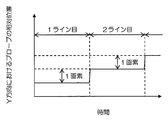
- FIG. 8 is a schematic diagram for explaining a conventional mode when the probe is relatively moved on the surface of the sample.
- 9A and 9B are diagrams showing the relationship between the time when the probe is relatively moved in the embodiment of FIG. 8 and the relative position of the probe, FIG. 9A is the relative position of the probe in the X direction, and FIG. The relative position of the probe in each direction is shown.
- the probe when the probe is relatively moved on the surface of the sample, the probe is reciprocated on one line by relatively moving the probe in the X direction (forward path) and in the direction opposite to the X direction (return path).
- the operation of shifting and the operation of shifting the probe by moving the probe one pixel at a time in the Y direction are alternately repeated. Thereby, the physical quantity during the reciprocating movement in each line is detected, and the feedback amount is adjusted using the physical quantity detected in each of the forward path and the return path.
- the relative velocity of the probe in the X direction is constant in both the forward path and the return path, as shown in FIG. 9A. That is, the probe whose relative movement is started in the X direction from the start position P1 moves relative to the forward path at a constant speed immediately after the start, and the relative movement direction is switched to the reverse direction at the turn-back position P2. At this time, the probe relatively moves on the return path at a constant speed immediately after switching of the direction of relative movement, and returns to the start position P1. In this way, the relative movement direction of the probe that relatively moves at a constant speed is alternately switched, so that the probe is relatively reciprocated in each line.
- the relative speed (scanning speed) of a probe in a scanning probe microscope is slow, and it takes about several minutes to measure the surface shape of the entire sample. Therefore, there has been a demand for a configuration in which the relative shape of the probe in the scanning probe microscope can be increased and the surface shape of the sample can be measured in a shorter time.
- the relative speed of the probe changes suddenly at the start position P1 and the turn-back position P2 because the probe starts moving in the opposite direction at the same time as the probe suddenly stops.
- the relative velocity of the probe changes rapidly at the start position P1.
- Such a rapid change in the relative velocity of the probe is likely to vibrate at the resonance frequency of the stage at the start position P1 and the turn-back position P2, and thus it is considered that periodic noise is likely to occur.
- the present invention has been made in view of the above circumstances, and an object of the present invention is to provide a scanning probe microscope that can increase the relative speed of a probe and that is less susceptible to noise in the measurement result of the surface shape of a sample.
- the reciprocation control unit switches the direction of the relative movement of the probe by gradually lowering the relative speed and then switching the direction, and gradually increasing the relative speed after switching to relatively move the probe. Move back and forth.
- the shift movement control unit relatively shifts the probe by gradually increasing the relative speed of the probe and then gradually decreasing the relative speed.
- the relative reciprocal movement of the probe is not continuously performed at the same position in the forward path and the backward path, but is performed at different positions in the forward path and the backward path, and the reciprocal movement is performed a plurality of times.
- the reciprocal movement is performed a plurality of times.
- the probe during the reciprocal movement, the probe is not relatively moved on a straight line along the first direction, but is gradually moved relatively in the second direction and then gradually in the opposite direction. Are repeatedly moved across a plurality of lines by repeating the relative movement operation.
- FIG. 7 is a diagram showing the relationship between the time when the probe is relatively moved and the relative position of the probe in the aspect of FIG. 6, and shows the relative position of the probe in the Y direction. It is the schematic for demonstrating the conventional aspect at the time of moving a probe relatively on the surface of a sample. It is the figure which showed the relationship between the time at the time of relatively moving a probe in the aspect of FIG. 8, and the relative position of a probe, and has shown the relative position of the probe in a X direction. It is the figure which showed the relationship between the time at the time of relatively moving a probe in the aspect of FIG. 8, and the relative position of a probe, and has shown the relative position of the probe in a Y direction.
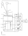
- the first piezoelectric element 11 is provided one by one at a position facing the X direction across the central axis L of the stage 1.
- the second piezoelectric element 12 is provided one by one at a position facing the Y direction perpendicular to the X direction across the central axis L of the stage 1. That is, the direction in which the pair of first piezoelectric elements 11 are arranged (X direction) and the direction in which the pair of second piezoelectric elements 12 are arranged (Y direction) are orthogonal to each other.
- the third piezoelectric element 13 is provided in an annular shape on the outer peripheral surface of the stage 1.
- the reciprocation control unit 51 controls the voltage applied to the first piezoelectric element 11.
- the probe 2 is reciprocated relative to the surface of the sample S by moving the probe 2 relative to the surface of the sample S in the X direction and the direction opposite to the X direction by the control of the reciprocation control unit 51. Can be moved. Thereby, the probe 2 is scanned on the surface of the sample S in a direction parallel to the X direction.
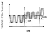
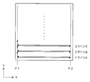
- FIG. 2 is a schematic diagram for explaining a first mode when the probe 2 is relatively moved on the surface of the sample S.
- FIG. 3A and 3B are diagrams showing the relationship between the time when the probe 2 is relatively moved in the mode of FIG. 2 and the relative position of the probe 2, and FIG. 3A is the relative position of the probe 2 in the X direction. 3B indicates the relative position of the probe 2 in the Y direction.
- the probe 2 is shifted by two pixels in the Y direction at the folding position P2, and is shifted by one pixel in the direction opposite to the Y direction every time the probe 2 returns from the folding position P2 to the start position P1. .
- the shift amount is different between the start position P1 and the turn-back position P2, before and after the relative movement direction of the probe 2 is switched to the X direction or the direction opposite to the X direction at the start position P1 and the turn-back position P2.
- the probe 2 moves relative to different positions (different lines) on the surface of the sample S.
- the probe 2 does not reciprocate on one line, but reciprocates across a plurality of lines.
- the relative speed of the probe 2 becomes discontinuous when the direction of the relative movement of the probe 2 is switched during the reciprocating movement or when the probe 2 is shifted. Can be prevented. That is, when the direction of relative movement of the probe 2 is switched during reciprocal movement, the relative speed of the probe 2 is rapidly increased by switching the direction after gradually decreasing the relative speed and gradually increasing the relative speed after switching. Can be prevented. Further, during the shift movement, the relative speed of the probe 2 can be prevented from changing suddenly by gradually increasing the relative speed of the probe 2 and then gradually decreasing the relative speed. Thereby, even when the relative speed of the probe 2 is increased, generation of periodic noise can be prevented, so that the relative speed of the probe 2 can be increased and the surface of the sample S can be increased. Noise is less likely to occur in the shape measurement results.
- the surface of the sample S is based only on the measurement results between the position P3 and the position P4 where the probe 2 is relatively moving at the constant speed. Are displayed on the display unit 6. Therefore, even when the relative speed of the probe 2 is increased, noise is not easily generated in the measurement result of the surface shape of the sample S, and an accurate measurement result can be obtained. Based on only the result, the uneven image of the surface of the sample S can be displayed on the display unit 6.
- the constant speed may be the same speed on the forward path and the return path, or may be a different speed.
- the probe 2 while the relative movement direction of the probe 2 is switched from the X direction to the reverse direction at the turn-back position P2, the probe 2 gradually moves in the Y direction and then reverses to the Y direction. It gradually returns to the original line by relative movement. As a result, the probe 2 relatively moves the same position (same line) on the surface of the sample S before and after the relative movement direction is switched from the X direction to the reverse direction at the folding position P2.
- the relative speed is changed when the direction of relative movement of the probe 2 is switched at the start position P1 and the turn-back position P2.
- the direction is switched after gradually decreasing the speed, and the relative speed is gradually increased after switching. Specifically, after gradually increasing the relative speed of the probe 2 in the X direction from the start position P1, the relative speed is maintained constant for a certain period of time, and then the relative speed is gradually decreased before the turn-back position P2 To switch to the opposite direction to the X direction.
- the probe 2 when the probe 2 is reciprocated, the probe 2 is relatively moved at a constant speed before the relative speed of the probe 2 is gradually decreased.
- the surface shape can be accurately measured.
- a concavo-convex image of the surface of the sample S is displayed on the display unit 6 based only on the measurement result when the probe 2 is relatively moving at the constant speed.
- FIG. 6 is a schematic diagram for explaining a third mode when the probe 2 is relatively moved on the surface of the sample S.
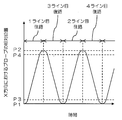
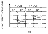
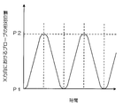
- FIG. 7A and 7B are diagrams showing the relationship between the time when the probe 2 is relatively moved in the mode of FIG. 6 and the relative position of the probe 2, and FIG. 7A is the relative position of the probe 2 in the X direction. 7B indicates the relative position of the probe 2 in the Y direction.
- the forward path is indicated by a solid line and the return path is indicated by a broken line.
- 6 and 7B for the sake of easy understanding, the period in which the probe 2 is repeatedly shifted in the Y direction and the direction opposite to the Y direction is shown larger than the actual period.
- the same position (same line) on the surface of the sample S along the direction opposite to the X direction and the X direction from the second line onward as shown in FIG. Will move relative to each other. That is, if the period when the probe 2 is repeatedly shifted and shifted in the direction opposite to the Y direction and the Y direction is appropriately set, the positions where the probe 2 passes in the forward path and the return path periodically overlap on the same line. Therefore, it is possible to obtain measurement results of the forward and return paths at the same position where they overlap.
- a concavo-convex image of the surface of the sample S is displayed on the display unit 6 based on the measurement results of the second and subsequent lines from which the measurement results of the forward path and the return path at the same position are obtained.
- the atomic force during the reciprocating movement is detected, and the amount of feedback by the feedback control unit 53 is adjusted using the atomic force detected in each of the forward path and the return path, so that the entire surface shape of the sample S Will be measured.
- the relative speed is changed when the direction of relative movement of the probe 2 is switched between the start position P1 and the turn-back position P2.
- the direction is switched after gradually decreasing the speed, and the relative speed is gradually increased after switching. Specifically, after gradually increasing the relative speed of the probe 2 in the X direction from the start position P1, the relative speed is maintained constant for a certain period of time, and then the relative speed is gradually decreased before the turn-back position P2 To switch to the opposite direction to the X direction.
- the relative speed of the probe 2 is gradually increased and then the relative speed is gradually decreased. It is like that. Specifically, while the probe 2 is relatively moved in the X direction and while being relatively moved in the direction opposite to the X direction (including while being maintained at a constant relative speed). After the probe 2 is gradually moved relatively in the Y direction, the operation of gradually moving the probe 2 in the direction opposite to the Y direction is repeated.
- the relative speed of the probe 2 becomes discontinuous when the direction of the relative movement of the probe 2 is switched during the reciprocating movement or when the probe 2 is shifted. Can be prevented. Therefore, even in the embodiments as shown in FIGS. 6, 7A and 7B, it is possible to prevent the occurrence of periodic noise when the relative speed of the probe 2 is increased, so that the relative speed of the probe 2 is increased. In addition, noise is less likely to occur in the measurement result of the surface shape of the sample S.
- the mechanism using the piezoelectric elements 11, 12, and 13 has been described as the mechanism for moving the probe 2 relative to the surface of the sample S.
- Examples of such piezoelectric elements 11, 12, and 13 include tube-type piezoelectric elements or stacked piezoelectric elements.
- the mechanism for moving the probe 2 relative to the surface of the sample S is not limited to the piezoelectric elements 11, 12, and 13, and the position of the stage 1 relative to the probe 2 using any other mechanism. Can be changed. Further, the mechanism may be such that the probe 2 is moved relative to the surface of the sample S by changing the position of the probe 2 relative to the stage 1 instead of changing the position of the stage 1 relative to the probe 2. .
- the present invention is not limited to the atomic force microscope, but can be applied to other scanning probe microscopes such as a tunneling microscope (STM: Scanning Tunneling Microscope).
- STM Scanning Tunneling Microscope
Landscapes
- Physics & Mathematics (AREA)
- Health & Medical Sciences (AREA)
- General Health & Medical Sciences (AREA)
- General Physics & Mathematics (AREA)
- Nuclear Medicine, Radiotherapy & Molecular Imaging (AREA)
- Radiology & Medical Imaging (AREA)
- Length Measuring Devices With Unspecified Measuring Means (AREA)
Abstract
Description
2 プローブ
3 発光部
4 受光部
5 制御部
6 表示部
11 第1圧電素子
12 第2圧電素子
13 第3圧電素子
51 往復移動制御部
52 シフト移動制御部
53 フィードバック制御部
54 測定制御部
Claims (9)
- 試料の表面に沿って相対移動するプローブと、
試料の表面に対して第1方向及び当該第1方向とは逆方向に前記プローブを相対移動させることにより往復移動させる往復移動制御部と、
試料の表面に対して前記第1方向に直交する第2方向に前記プローブを相対移動させることによりシフト移動させるシフト移動制御部と、
前記往復移動制御部及び前記シフト移動制御部により試料の表面に沿って相対移動される前記プローブの前記第1方向及び前記第2方向に直交する方向への相対的な変位量に基づいて、試料の表面形状を測定する測定制御部とを備え、
前記往復移動制御部は、前記プローブの相対移動の方向を切り替えるときに、相対速度を徐々に低下させてから方向を切り替え、切替後に相対速度を徐々に上昇させることにより、前記プローブを相対的に往復移動させ、
前記シフト移動制御部は、前記プローブの相対速度を徐々に上昇させた後、相対速度を徐々に低下させることにより、前記プローブを相対的にシフト移動させることを特徴とする走査型プローブ顕微鏡。 - 前記往復移動制御部は、前記プローブの相対速度を徐々に低下させる前に、一定速度で前記プローブを相対移動させることを特徴とする請求項1に記載の走査型プローブ顕微鏡。
- 表示部をさらに備え、
前記測定制御部は、上記一定速度で前記プローブを相対移動させているときの測定結果のみに基づいて、前記表示部に試料表面の凹凸画像を表示させることを特徴とする請求項2に記載の走査型プローブ顕微鏡。 - 前記プローブは、前記往復移動制御部により相対移動の方向が切り替えられる前と後とで、試料の表面における異なる位置を相対移動することを特徴とする請求項1~3のいずれかに記載の走査型プローブ顕微鏡。
- 前記プローブは、前記往復移動制御部による相対的な往復移動が複数回行われることによって、試料の表面における同じ位置を前記第1方向及び当該第1方向とは逆方向に沿って相対移動することを特徴とする請求項4に記載の走査型プローブ顕微鏡。
- 前記プローブは、前記往復移動制御部により相対移動の方向が切り替えられる前と後とで、試料の表面における同じ位置を相対移動することを特徴とする請求項1~3のいずれかに記載の走査型プローブ顕微鏡。
- 前記プローブは、前記往復移動制御部により相対移動の方向が切り替えられている間に、前記シフト移動制御部により第2方向に徐々に相対移動した後、当該第2方向とは逆方向に徐々に相対移動することを特徴とする請求項6に記載の走査型プローブ顕微鏡。
- 前記プローブは、前記往復移動制御部により第1方向に相対移動されている間、及び、当該第1方向とは逆方向に相対移動されている間に、前記シフト移動制御部により第2方向に徐々に相対移動した後、当該第2方向とは逆方向に徐々に相対移動する動作を繰り返すことを特徴とする請求項1に記載の走査型プローブ顕微鏡。
- 前記プローブは、前記往復移動制御部による相対的な往復移動が複数回行われることによって、試料の表面における同じ位置を前記第1方向及び当該第1方向とは逆方向に沿って相対移動することを特徴とする請求項8に記載の走査型プローブ顕微鏡。
Priority Applications (4)
| Application Number | Priority Date | Filing Date | Title |
|---|---|---|---|
| JP2017512495A JP6460227B2 (ja) | 2015-04-14 | 2015-04-14 | 走査型プローブ顕微鏡 |
| PCT/JP2015/061494 WO2016166816A1 (ja) | 2015-04-14 | 2015-04-14 | 走査型プローブ顕微鏡 |
| US15/566,164 US10564180B2 (en) | 2015-04-14 | 2015-04-14 | Scanning probe microscope using gradual increases and decreases in relative speed when shifting and reciprocating the scanned probe across a sample |
| CN201580078724.0A CN107533083B (zh) | 2015-04-14 | 2015-04-14 | 扫描型探针显微镜 |
Applications Claiming Priority (1)
| Application Number | Priority Date | Filing Date | Title |
|---|---|---|---|
| PCT/JP2015/061494 WO2016166816A1 (ja) | 2015-04-14 | 2015-04-14 | 走査型プローブ顕微鏡 |
Publications (1)
| Publication Number | Publication Date |
|---|---|
| WO2016166816A1 true WO2016166816A1 (ja) | 2016-10-20 |
Family
ID=57125825
Family Applications (1)
| Application Number | Title | Priority Date | Filing Date |
|---|---|---|---|
| PCT/JP2015/061494 Ceased WO2016166816A1 (ja) | 2015-04-14 | 2015-04-14 | 走査型プローブ顕微鏡 |
Country Status (4)
| Country | Link |
|---|---|
| US (1) | US10564180B2 (ja) |
| JP (1) | JP6460227B2 (ja) |
| CN (1) | CN107533083B (ja) |
| WO (1) | WO2016166816A1 (ja) |
Cited By (6)
| Publication number | Priority date | Publication date | Assignee | Title |
|---|---|---|---|---|
| US11709156B2 (en) | 2017-09-18 | 2023-07-25 | Waters Technologies Corporation | Use of vapor deposition coated flow paths for improved analytical analysis |
| US11709155B2 (en) | 2017-09-18 | 2023-07-25 | Waters Technologies Corporation | Use of vapor deposition coated flow paths for improved chromatography of metal interacting analytes |
| US11918936B2 (en) | 2020-01-17 | 2024-03-05 | Waters Technologies Corporation | Performance and dynamic range for oligonucleotide bioanalysis through reduction of non specific binding |
| US12180581B2 (en) | 2017-09-18 | 2024-12-31 | Waters Technologies Corporation | Use of vapor deposition coated flow paths for improved chromatography of metal interacting analytes |
| US12181452B2 (en) | 2017-09-18 | 2024-12-31 | Waters Technologies Corporation | Use of vapor deposition coated flow paths for improved chromatography of metal interacting analytes |
| US12352734B2 (en) | 2020-09-24 | 2025-07-08 | Waters Technologies Corporation | Chromatographic hardware improvements for separation of reactive molecules |
Families Citing this family (5)
| Publication number | Priority date | Publication date | Assignee | Title |
|---|---|---|---|---|
| JP3208956U (ja) * | 2016-10-19 | 2017-03-02 | 株式会社島津製作所 | 走査型プローブ顕微鏡 |
| FR3071627B1 (fr) * | 2017-09-25 | 2022-02-25 | Concept Scient Instruments | Procede de commande d'une sonde |
| US11415596B2 (en) * | 2018-01-29 | 2022-08-16 | Shimadzu Corporation | Scanning probe microscope and analysis method |
| JP6631650B2 (ja) * | 2018-04-18 | 2020-01-15 | 株式会社島津製作所 | 走査型プローブ顕微鏡 |
| JP7625971B2 (ja) * | 2021-05-27 | 2025-02-04 | 株式会社島津製作所 | 走査型プローブ顕微鏡および制御方法 |
Citations (4)
| Publication number | Priority date | Publication date | Assignee | Title |
|---|---|---|---|---|
| JPH08235651A (ja) * | 1995-02-23 | 1996-09-13 | Canon Inc | 情報処理装置 |
| JP2001194284A (ja) * | 2000-01-11 | 2001-07-19 | Seiko Instruments Inc | 探針の走査方法 |
| JP2002350318A (ja) * | 2001-05-25 | 2002-12-04 | Olympus Optical Co Ltd | スキャナ装置 |
| JP2010066077A (ja) * | 2008-09-09 | 2010-03-25 | Yokohama National Univ | 原子間力顕微鏡装置 |
Family Cites Families (8)
| Publication number | Priority date | Publication date | Assignee | Title |
|---|---|---|---|---|
| US7053369B1 (en) * | 2001-10-19 | 2006-05-30 | Rave Llc | Scan data collection for better overall data accuracy |
| US7009172B2 (en) * | 2003-03-06 | 2006-03-07 | Board Of Regents Of The University And Community College System Of Nevada, Reno | Method and apparatus for imaging using continuous non-raster patterns |
| JP4073847B2 (ja) * | 2003-08-25 | 2008-04-09 | エスアイアイ・ナノテクノロジー株式会社 | 走査型プローブ顕微鏡及び走査方法 |
| JP4432806B2 (ja) | 2005-03-09 | 2010-03-17 | 株式会社島津製作所 | 走査型プローブ顕微鏡 |
| JP2008089542A (ja) * | 2006-10-05 | 2008-04-17 | Hitachi Kenki Fine Tech Co Ltd | 走査型プローブ顕微鏡の探針制御方法 |
| US20090107222A1 (en) * | 2007-10-29 | 2009-04-30 | Daniel Yves Abramovitch | Scanning Probe Microscope with Improved Scanning Speed |
| EP2428804B1 (en) * | 2010-09-14 | 2015-01-14 | Consiglio Nazionale Delle Ricerche | A method for driving a scanning probe microscope at elevated scan frequencies |
| DE112015006610T5 (de) * | 2015-07-07 | 2018-03-08 | Olympus Corporation | Rasterkraftmikroskop und Steuerverfahren dafür |
-
2015
- 2015-04-14 CN CN201580078724.0A patent/CN107533083B/zh active Active
- 2015-04-14 US US15/566,164 patent/US10564180B2/en active Active
- 2015-04-14 WO PCT/JP2015/061494 patent/WO2016166816A1/ja not_active Ceased
- 2015-04-14 JP JP2017512495A patent/JP6460227B2/ja active Active
Patent Citations (4)
| Publication number | Priority date | Publication date | Assignee | Title |
|---|---|---|---|---|
| JPH08235651A (ja) * | 1995-02-23 | 1996-09-13 | Canon Inc | 情報処理装置 |
| JP2001194284A (ja) * | 2000-01-11 | 2001-07-19 | Seiko Instruments Inc | 探針の走査方法 |
| JP2002350318A (ja) * | 2001-05-25 | 2002-12-04 | Olympus Optical Co Ltd | スキャナ装置 |
| JP2010066077A (ja) * | 2008-09-09 | 2010-03-25 | Yokohama National Univ | 原子間力顕微鏡装置 |
Cited By (8)
| Publication number | Priority date | Publication date | Assignee | Title |
|---|---|---|---|---|
| US11709156B2 (en) | 2017-09-18 | 2023-07-25 | Waters Technologies Corporation | Use of vapor deposition coated flow paths for improved analytical analysis |
| US11709155B2 (en) | 2017-09-18 | 2023-07-25 | Waters Technologies Corporation | Use of vapor deposition coated flow paths for improved chromatography of metal interacting analytes |
| US12180581B2 (en) | 2017-09-18 | 2024-12-31 | Waters Technologies Corporation | Use of vapor deposition coated flow paths for improved chromatography of metal interacting analytes |
| US12181452B2 (en) | 2017-09-18 | 2024-12-31 | Waters Technologies Corporation | Use of vapor deposition coated flow paths for improved chromatography of metal interacting analytes |
| US12416607B2 (en) | 2017-09-18 | 2025-09-16 | Waters Technologies Corporation | Use of vapor deposition coated flow paths for improved chromatography of metal interacting analytes |
| US12510520B2 (en) | 2017-09-18 | 2025-12-30 | Waters Technologies Corporation | Use of vapor deposition coated flow paths for improved analytical analysis |
| US11918936B2 (en) | 2020-01-17 | 2024-03-05 | Waters Technologies Corporation | Performance and dynamic range for oligonucleotide bioanalysis through reduction of non specific binding |
| US12352734B2 (en) | 2020-09-24 | 2025-07-08 | Waters Technologies Corporation | Chromatographic hardware improvements for separation of reactive molecules |
Also Published As
| Publication number | Publication date |
|---|---|
| CN107533083B (zh) | 2020-10-30 |
| US10564180B2 (en) | 2020-02-18 |
| US20180088148A1 (en) | 2018-03-29 |
| JP6460227B2 (ja) | 2019-01-30 |
| CN107533083A (zh) | 2018-01-02 |
| JPWO2016166816A1 (ja) | 2018-02-08 |
Similar Documents
| Publication | Publication Date | Title |
|---|---|---|
| JP6460227B2 (ja) | 走査型プローブ顕微鏡 | |
| JP6691272B2 (ja) | 化学的撮像用の原子間力顕微鏡赤外線分光法及び装置 | |
| JP5210894B2 (ja) | 光走査型内視鏡 | |
| JP5775340B2 (ja) | 光偏向器 | |
| JP6324817B2 (ja) | 光スキャナ及び光偏向器の制御方法 | |
| JP6579893B2 (ja) | 振動型アクチュエータの制御装置と制御方法、駆動装置、撮像装置及び自動ステージ | |
| JP6746314B2 (ja) | 制御装置、これを備えた装置およびプログラム | |
| JP6311322B2 (ja) | 光偏向装置および画像表示装置並びにヘッドアップディスプレイ | |
| JP5184909B2 (ja) | 揺動体装置及び光偏向装置 | |
| US20100085618A1 (en) | Oscillator device, optical deflecting device and method of controlling the same | |
| JPWO2016189591A1 (ja) | 走査型内視鏡およびその制御方法 | |
| JP5024452B2 (ja) | 走査装置 | |
| JP2009058616A (ja) | 揺動体装置、光偏向装置、及びそれを用いた画像形成装置 | |
| JP5188315B2 (ja) | 揺動体装置、光偏向装置、及びそれを用いた光学機器 | |
| JP2012256037A (ja) | 光走査装置とそれに用いる光学反射素子 | |
| JP6842754B2 (ja) | 走査型プローブ顕微鏡 | |
| WO2016116963A1 (ja) | 光走査方法及び光走査装置 | |
| KR102139039B1 (ko) | 멤스 미러 및 이의 리사쥬 스캔 구동방법 | |
| CN109219752B (zh) | 扫描型探针显微镜 | |
| US10488641B2 (en) | Scanning microscope | |
| JP4816414B2 (ja) | 走査型プローブ顕微鏡 | |
| JP2019074329A (ja) | 測距装置及び光走査装置 | |
| JP2012053269A (ja) | 2次元光走査装置 | |
| CN115840283A (zh) | 一种扫描器件、驱动条件设置方法及扫描显示模组 | |
| JP4998291B2 (ja) | 光走査装置 |
Legal Events
| Date | Code | Title | Description |
|---|---|---|---|
| 121 | Ep: the epo has been informed by wipo that ep was designated in this application |
Ref document number: 15889154 Country of ref document: EP Kind code of ref document: A1 |
|
| ENP | Entry into the national phase |
Ref document number: 2017512495 Country of ref document: JP Kind code of ref document: A |
|
| WWE | Wipo information: entry into national phase |
Ref document number: 15566164 Country of ref document: US |
|
| NENP | Non-entry into the national phase |
Ref country code: DE |
|
| 122 | Ep: pct application non-entry in european phase |
Ref document number: 15889154 Country of ref document: EP Kind code of ref document: A1 |