WO2016163405A1 - 支持方法、加工方法、及びこれらの方法を実行する装置 - Google Patents
支持方法、加工方法、及びこれらの方法を実行する装置 Download PDFInfo
- Publication number
- WO2016163405A1 WO2016163405A1 PCT/JP2016/061276 JP2016061276W WO2016163405A1 WO 2016163405 A1 WO2016163405 A1 WO 2016163405A1 JP 2016061276 W JP2016061276 W JP 2016061276W WO 2016163405 A1 WO2016163405 A1 WO 2016163405A1
- Authority
- WO
- WIPO (PCT)
- Prior art keywords
- pin
- support
- tool
- processing
- wing
- Prior art date
- Legal status (The legal status is an assumption and is not a legal conclusion. Google has not performed a legal analysis and makes no representation as to the accuracy of the status listed.)
- Ceased
Links
Images

Classifications
-
- B—PERFORMING OPERATIONS; TRANSPORTING
- B23—MACHINE TOOLS; METAL-WORKING NOT OTHERWISE PROVIDED FOR
- B23Q—DETAILS, COMPONENTS, OR ACCESSORIES FOR MACHINE TOOLS, e.g. ARRANGEMENTS FOR COPYING OR CONTROLLING; MACHINE TOOLS IN GENERAL CHARACTERISED BY THE CONSTRUCTION OF PARTICULAR DETAILS OR COMPONENTS; COMBINATIONS OR ASSOCIATIONS OF METAL-WORKING MACHINES, NOT DIRECTED TO A PARTICULAR RESULT
- B23Q3/00—Devices holding, supporting, or positioning work or tools, of a kind normally removable from the machine
- B23Q3/02—Devices holding, supporting, or positioning work or tools, of a kind normally removable from the machine for mounting on a work-table, tool-slide, or analogous part
- B23Q3/06—Work-clamping means
- B23Q3/062—Work-clamping means adapted for holding workpieces having a special form or being made from a special material
-
- B—PERFORMING OPERATIONS; TRANSPORTING
- B23—MACHINE TOOLS; METAL-WORKING NOT OTHERWISE PROVIDED FOR
- B23C—MILLING
- B23C3/00—Milling particular work; Special milling operations; Machines therefor
- B23C3/16—Working surfaces curved in two directions
- B23C3/18—Working surfaces curved in two directions for shaping screw-propellers, turbine blades, or impellers
-
- B—PERFORMING OPERATIONS; TRANSPORTING
- B23—MACHINE TOOLS; METAL-WORKING NOT OTHERWISE PROVIDED FOR
- B23Q—DETAILS, COMPONENTS, OR ACCESSORIES FOR MACHINE TOOLS, e.g. ARRANGEMENTS FOR COPYING OR CONTROLLING; MACHINE TOOLS IN GENERAL CHARACTERISED BY THE CONSTRUCTION OF PARTICULAR DETAILS OR COMPONENTS; COMBINATIONS OR ASSOCIATIONS OF METAL-WORKING MACHINES, NOT DIRECTED TO A PARTICULAR RESULT
- B23Q3/00—Devices holding, supporting, or positioning work or tools, of a kind normally removable from the machine
- B23Q3/02—Devices holding, supporting, or positioning work or tools, of a kind normally removable from the machine for mounting on a work-table, tool-slide, or analogous part
-
- B—PERFORMING OPERATIONS; TRANSPORTING
- B23—MACHINE TOOLS; METAL-WORKING NOT OTHERWISE PROVIDED FOR
- B23Q—DETAILS, COMPONENTS, OR ACCESSORIES FOR MACHINE TOOLS, e.g. ARRANGEMENTS FOR COPYING OR CONTROLLING; MACHINE TOOLS IN GENERAL CHARACTERISED BY THE CONSTRUCTION OF PARTICULAR DETAILS OR COMPONENTS; COMBINATIONS OR ASSOCIATIONS OF METAL-WORKING MACHINES, NOT DIRECTED TO A PARTICULAR RESULT
- B23Q3/00—Devices holding, supporting, or positioning work or tools, of a kind normally removable from the machine
- B23Q3/02—Devices holding, supporting, or positioning work or tools, of a kind normally removable from the machine for mounting on a work-table, tool-slide, or analogous part
- B23Q3/10—Auxiliary devices, e.g. bolsters, extension members
-
- F—MECHANICAL ENGINEERING; LIGHTING; HEATING; WEAPONS; BLASTING
- F01—MACHINES OR ENGINES IN GENERAL; ENGINE PLANTS IN GENERAL; STEAM ENGINES
- F01D—NON-POSITIVE DISPLACEMENT MACHINES OR ENGINES, e.g. STEAM TURBINES
- F01D25/00—Component parts, details, or accessories, not provided for in, or of interest apart from, other groups
-
- F—MECHANICAL ENGINEERING; LIGHTING; HEATING; WEAPONS; BLASTING
- F02—COMBUSTION ENGINES; HOT-GAS OR COMBUSTION-PRODUCT ENGINE PLANTS
- F02C—GAS-TURBINE PLANTS; AIR INTAKES FOR JET-PROPULSION PLANTS; CONTROLLING FUEL SUPPLY IN AIR-BREATHING JET-PROPULSION PLANTS
- F02C7/00—Features, components parts, details or accessories, not provided for in, or of interest apart form groups F02C1/00 - F02C6/00; Air intakes for jet-propulsion plants
-
- F—MECHANICAL ENGINEERING; LIGHTING; HEATING; WEAPONS; BLASTING
- F04—POSITIVE - DISPLACEMENT MACHINES FOR LIQUIDS; PUMPS FOR LIQUIDS OR ELASTIC FLUIDS
- F04D—NON-POSITIVE-DISPLACEMENT PUMPS
- F04D29/00—Details, component parts, or accessories
- F04D29/26—Rotors specially for elastic fluids
- F04D29/32—Rotors specially for elastic fluids for axial flow pumps
- F04D29/38—Blades
-
- F—MECHANICAL ENGINEERING; LIGHTING; HEATING; WEAPONS; BLASTING
- F04—POSITIVE - DISPLACEMENT MACHINES FOR LIQUIDS; PUMPS FOR LIQUIDS OR ELASTIC FLUIDS
- F04D—NON-POSITIVE-DISPLACEMENT PUMPS
- F04D29/00—Details, component parts, or accessories
- F04D29/60—Mounting; Assembling; Disassembling
Definitions
- the present invention relates to a method for supporting a long object, a processing method, and an apparatus for executing these methods.
- This application claims priority based on Japanese Patent Application No. 2015-079364 for which it applied to Japan on April 8, 2015, and uses the content here.
- moving blades such as a compressor.
- This moving blade has a wing body extending in one direction and a blade root provided at an end portion in one direction of the wing body.
- a processing method of a wing which is a kind of long object
- a processing method described in Patent Document 1 in the process of processing a blade from a material, a fixed portion is formed at the end of the blade root and on the end opposite to the blade body. Then, in a state where the fixed portion is supported by a holder or the like, the blade body forming portion that becomes the blade body in the material is processed. Thereafter, in this processing method, the fixing portion is separated from the blade root.
- an object of the present invention is to provide a support method capable of stably supporting a long object, a processing method using this support method, and an apparatus for executing these methods.
- the support as a first aspect according to the invention for achieving the above object is: In a support device for supporting a long object in one direction, a plurality of cylinders for supporting the long object and a cylinder to which the plurality of cylinders are attached from a direction having a direction component perpendicular to the one direction.
- the cylinder includes a pin, a casing that covers the base end portion of the pin so as to be displaceable in a pin extending direction in which the pin extends, and the elongated object disposed on the distal end side of the pin
- a follow-up mechanism for causing the position of the pin in the pin extending direction to follow the position of the surface of the elongated object in the pin extending direction so that the tip of the pin contacts the surface of the pin, and the pin with respect to the casing
- a pin restraining mechanism for restraining a relative position in the pin extending direction, and each casing of the plurality of cylinders is fixed to the cylinder base.
- each of the plurality of cylinders has a follow-up mechanism, and therefore, the surface of the long object has a curved surface, or the surface of the long object has a plurality of irregularities.
- a plurality of pins can be brought into contact with the surface of the long object.
- the said support tool has a pin restraint mechanism, the movement of a pin can be restrained in the state in which all the pins are contacting the surface of a long thing. For this reason, the said support tool can support a long thing stably.
- the follow-up mechanism includes an elastic member that is disposed in the casing and biases the pin in a direction in which the pin extends and protrudes from the casing.
- the pin restraining mechanism is disposed in the casing, is deformed by receiving a fluid pressure, grips the pin, and extends the pin with respect to the casing. It has a pin grip member which restrains the relative position in the present direction.
- the support as a fourth aspect according to the invention for achieving the above object is:
- the casing is formed with an inflow port for receiving a fluid for deforming the pin gripping member, and the cylinder base receives the fluid from the outside, and the casing A flow path for guiding the fluid to the inlet is formed.
- the support as a fifth aspect according to the invention for achieving the above object is:
- the flow path is provided for each of the plurality of cylinders and the main flow path that receives the fluid from the outside, and branches from the main flow path to the inlets of the plurality of casings. And a branched flow path connected thereto.
- a line for supplying fluid to the cylinder base can be integrated.
- a support device as a sixth aspect according to the invention for achieving the above object is as follows: The support tool according to any one of the first to fifth aspects, a workpiece gripper that grips an end of the elongated object in the one direction, and a direction of the workpiece gripper and a position of the workpiece gripper are changed. A gripper moving mechanism.
- the long object can be supported more stably by holding the end of the long object with the work gripping machine while supporting the predetermined region in one direction of the long object with the support tool. it can.
- a support device as a seventh aspect according to the invention for achieving the above object is as follows:
- the support device according to the sixth aspect includes a base to which the gripper moving mechanism is attached, and a support moving mechanism that moves the support relative to the base.
- the position of the support tool can be changed according to the length of the long object in one direction and the position of processing (processing, inspection, etc.) for the long object.
- a processing apparatus as an eighth aspect according to the invention for achieving the above object is as follows: The support tool according to any one of the first to fifth aspects, a tool driving mechanism that drives the processing tool, and a tool driving mechanism that is mounted with a processing tool that processes the long object supported by the support tool; A tool moving mechanism for moving at least a portion on which the processing tool is mounted.
- This processing apparatus can process a long object that is stably supported by a support.
- a processing apparatus as a ninth aspect according to the invention for achieving the above object is as follows: The support device according to the sixth or seventh aspect, and a tool driving mechanism for driving the processing tool mounted with a processing tool for processing the long object gripped by the work gripper and supported by the support tool. And a tool moving mechanism for moving at least a portion on which the processing tool is mounted by the tool driving mechanism.
- the long object can be supported more stably by holding the end of the long object with the work gripper while supporting the predetermined region in one direction of the long object with the support tool. .
- the chatter vibration of the process part during a process can be suppressed.
- a supporting method as a tenth aspect of the invention for achieving the above object is as follows: In a supporting method for supporting a long object that is long in one direction, a preparation step of arranging a plurality of pins, and contacting the long object to tip portions of the plurality of pins arranged in the preparation step, a plurality of pins A supporting step of supporting the long object with the pins, and in the preparation step, the pin extending directions in which the pins extend are aligned with each other and supported by the supporting step.
- the plurality of pins are arranged so as to face a direction having a directional component perpendicular to the one direction of the long object when the long object is at the tip of the plurality of pins.
- the front ends of the plurality of pins are respectively in contact with the surface of the long object in the pin extending direction.
- the pin is extended to the position of the surface of the long object.
- the surface of the long object is formed even when the surface of the long object has a curved surface or a plurality of irregularities are formed on the surface of the long object.
- a plurality of pins can be brought into contact with each other.
- the movement of a pin in order to perform a pin restraint process, the movement of a pin can be restrained in the state in which all the pins are contacting the surface of a long thing. For this reason, in the said support method, a long thing can be supported stably.
- the supporting method as the eleventh aspect according to the invention for achieving the above object is as follows: In the method for supporting the long object using the support tool according to any one of the first to fifth aspects, a preparation step of arranging the support tool, and a plurality of the support tools arranged in the preparation step The long object is brought into contact with the tip of the pin, and the support process of supporting the long object with a plurality of the pins is performed. In the preparation process, the pin extending direction is the support process.
- the support tool is arranged so that the long object is in a direction having a direction component perpendicular to the one direction of the long object when supported by
- the follower mechanism extends the pin to the position of the surface of the long object in the pin extending direction.
- the pin restraining mechanism restrains the positions of the plurality of pins in the pin extending direction. Pin restraining step.
- the surface of the long object is formed even when the surface of the long object has a curved surface or when a plurality of irregularities are formed on the surface of the long object.
- a plurality of pins can be brought into contact with each other.
- the movement of a pin can be restrained in the state which all the pins are contacting the surface of a long thing. For this reason, a long object can be stably supported also by the said supporting method.
- a processing method as a twelfth aspect according to the invention for achieving the above object is as follows: By the supporting method of the tenth or eleventh aspect, the long material or the long intermediate material as the long material is supported, and the long material or the long material supported by the supporting method. A processing step for processing the intermediate product is executed.
- a processing method as a thirteenth aspect according to the invention for achieving the above object is as follows: In the processing method according to the twelfth aspect, a workpiece gripping step of gripping an end portion in the one direction of the long material or the long material intermediate product is performed at least during execution of the processing step.
- the processing method while supporting a predetermined region in one direction of the long material or the long intermediate product with a plurality of pins, the end of the long material or the long intermediate product is gripped. Further, it is possible to more stably support the long material or the intermediate product. For this reason, in the said processing method, the chatter vibration of the process part during a process can be suppressed. As a result, in this machining method, it is possible to suppress the roughness of the machined surface, damage to the machining tool, and the like due to chatter vibration.
- the processing method as the fourteenth aspect according to the invention for achieving the above object is as follows:
- the long material or the long product intermediate product is provided at a wing body extending in the one direction and an end portion of the wing body in the one direction.
- a wing material or a wing intermediate product of a wing having a wing fixing portion and in the supporting step, a wing body forming portion that becomes the wing body in the wing material or the wing intermediate product is provided with a plurality of the pins.
- a portion including the side opposite to the side where the plurality of pins are in contact is processed.
- a processing method as a fifteenth aspect according to the invention for achieving the above object is as follows:
- the long material or the long intermediate product is a blade provided in the one direction and a blade provided at an end of the blade in the one direction.
- a wing material or a wing intermediate product of a wing having a fixed portion and in the supporting step, a wing body forming portion that becomes the wing body in the wing material or the wing intermediate product is supported by a plurality of the pins
- the blade fixing forming portion or the blade fixing portion that becomes the blade fixing portion in the blade material or the blade intermediate product is gripped
- the blade body forming portion includes a plurality of blade fixing portions. The portion including the side opposite to the side with which the pin is in contact is processed.
- a long object can be stably supported.
- the long object handled in this embodiment is a wing 1, a metal wing material 1a for forming the wing 1, and a wing intermediate in the process of forming the wing 1 from the wing material 1a.
- Product 1b (see FIG. 2).
- the blade material 1a and the blade intermediate product 1b are both long in one direction.
- the blade 1, the blade material 1a, and the blade intermediate product 1b are collectively referred to as a blade forming product 1d.
- the blade 1 has a blade body 2 that is long in one longitudinal direction Dw, and a blade root 3 that is provided at an end of the blade body 2 in the longitudinal direction Dw.
- the surface of the wing body 2 forms a three-dimensional curved surface.
- the blade root 3 is, for example, a portion fixed to the rotor shaft of the rotary machine, in other words, a blade fixing portion.
- a part of the blade 1 that fixes the blade 1 to a certain member is a blade root.
- wing 1 to the casing of a rotary machine is also handled as a blade root in this application.
- the wing material 1 a has a rectangular parallelepiped shape whose outer shape is larger than that of the wing 1.
- the processing apparatus M that processes the blade material 1 a into the blade 1 includes a support tool 10 that supports the blade forming product 1 d and a fluid supply that supplies a driving fluid to the support tool 10.
- the machine 40, the processing machine 50 which processes the blade raw material 1a, and the control apparatus (not shown) which controls the fluid supply device 40 and the processing machine 50 are provided.
- the vertical direction is the Z direction
- the direction perpendicular to the Z direction is the Y direction
- the direction perpendicular to the Z direction and the Y direction is the X direction.
- the processing machine 50 includes a base 51, a workpiece gripper 52, a gripper moving mechanism 53, a support tool moving mechanism 54, a tool driving mechanism 55, and a tool moving mechanism 56.
- the work gripper 52 grips the end of the blade forming product 1d in the longitudinal direction Dw.
- the gripper moving mechanism 53 moves the workpiece gripper 52 relative to the base 51.
- the support tool moving mechanism 54 moves the support tool 10 relative to the base 51.
- the tool driving mechanism 55 drives a processing tool for processing the blade material 1a.
- the tool moving mechanism 56 moves the tool driving mechanism 55 relative to the base 51 at least at a portion where the processing tool is mounted.
- the gripping machine moving mechanism 53 moves the workpiece gripping machine 52 at least relative to the base 51 in the X direction, the Y direction, the Z direction, and the circumferential direction based on the gripping axis Ag of the workpiece gripping machine 52 extending in the Y direction.
- the support tool moving mechanism 54 moves the support tool 10 relative to the base 51 at least in the X direction, the Y direction, and the Z direction.
- the tool drive mechanism 55 includes a spindle 55s on which a disk or columnar processing tool 59 is mounted, and a spindle rotation mechanism 55d that rotates the spindle 55s.
- the tool moving mechanism 56 moves at least the spindle 55 s in the tool driving mechanism 55 relative to the base 51 at least in the X direction, the Y direction, and the Z direction.
- the fluid supplier 40 is provided in the fluid line 42, a fluid discharge source 41 that discharges a fluid having a pressure equal to or higher than a certain pressure, a fluid line 42 that guides the fluid from the fluid discharge source 41 to the support 10, and the fluid line 42.
- the fluid discharged from the fluid discharge source 41 may be a gas such as air or a liquid such as oil.
- the support 10 has a plurality of support cylinders 20 and a cylinder base 11 to which the plurality of support cylinders 20 are attached.
- the plurality of support cylinders 20 are attached to the cylinder base 11.
- the support cylinder 20 includes a pin 21, a casing 25, a follow-up mechanism 31, and a pin restraining mechanism 35.
- the casing 25 covers the base end portion of the pin 21 so as to be displaceable in the pin extending direction Dp in which the pin 21 extends.
- the follow-up mechanism 31 causes the position of the pin 21 in the pin extending direction Dp to follow the movement of the surface position of the blade forming product 1d in the pin extending direction Dp.
- the pin restraining mechanism 35 restrains the relative position of the pin 21 with respect to the casing 25 in the pin extending direction Dp.
- one side of the pin extending direction Dp is a distal end side, and the opposite side is a proximal end side.
- the casing 25 is provided with a pin base end portion that is a portion on the base end side of the pin 21, a follow-up mechanism 31, and a pin restraining mechanism 35, and from the fluid supply device 40.
- a cylinder chamber 26 into which fluid flows is formed.
- the casing 25 is formed with a pin hole 27 into which the pin 21 is inserted through the cylinder chamber 26 in the pin extending direction Dp, and an inlet 28 for receiving the fluid from the fluid supplier 40 in the cylinder chamber 26. Has been.
- the pin 21 has a pin body 22 that is cylindrical with an axis extending in the pin extending direction Dp as a center, and a contact seat 24 that contacts the wing forming product 1d.
- the pin main body 22 is formed with a cylindrical hole 23 that is recessed from the proximal end side toward the distal end side.
- the contact seat 24 is fixed to the tip side of the pin body 22 in the pin extending direction Dp.
- the contact seat 24 closes the opening on the distal end side in the pin extending direction Dp. Therefore, this contact seat 24 forms the tip of the pin 21.
- the follow-up mechanism 31 includes a guide rod 32 and a spring 33 as an elastic member.
- the guide rod 32 guides the movement of the pin 21 in the pin extending direction Dp.
- the spring 33 biases the pin 21 in the pin extending direction Dp and to the side protruding from the casing 25.
- the guide rod 32 has a cylindrical shape and extends in the pin extending direction Dp in the cylinder chamber 26 from the bottom forming the base end side of the casing 25.
- the distal end side portion of the guide rod 32 is inserted into the hole 23 of the pin body 22.
- the spring 33 is disposed in the hole 23 of the pin body 22 and between the guide rod 32 and the bottom surface of the hole 23.
- the spring 33 is in contact with the pin body 22 and the guide rod 32 even when the pin 21 is located at the maximum projecting position.
- the spring 33 contracts when a load is applied to the pin 21 located at the maximum projecting position toward the proximal end side in the pin extending direction Dp, and a biasing force is generated on the distal end side in the pin extending direction Dp.
- the outer periphery of the base end portion of the pin 21 is covered with a cylindrical collet 36.
- the collet 36 is formed to be elastically deformable from the outer peripheral side toward the inner peripheral side.
- a fluid chamber 29 into which the fluid from the fluid supplier 40 flows is formed between the outer peripheral side of the collet 36 and the inner peripheral surface of the casing 25.
- the pin restraining mechanism 35 includes a collet 36, a fluid chamber 29 in the casing 25, and an inflow port 28 formed in the casing 25.
- the casings 25 of the plurality of support cylinders 20 are embedded and fixed to the cylinder base 11.
- the pin extending directions Dp of the pins 21 of the plurality of support cylinders 20 are aligned with each other when the casing 25 is fixed to the cylinder base 11. That is, the pin extending direction Dp in each pin 21 is the same direction. In addition, the pin extending direction Dp in each pin 21 may not be the same direction. Further, the positions of the pins 21 of the plurality of support cylinders 20 in the pin extending direction Dp are the same as each other in a state where the pins 21 are located at the maximum projecting positions.
- the cylinder base 11 is formed with a flow path 12 that receives the fluid from the fluid line 42 of the fluid supplier 40 and guides the fluid to the inlet 28 of each casing 25 in the plurality of support cylinders 20.
- the flow path 12 is connected to a fluid line 42 of the fluid supplier 40.
- the flow path 12 includes a main flow path 13 and a plurality of branch flow paths 14.
- the main flow path 13 receives the fluid from the fluid line 42.
- the branch channel 14 branches from the main channel 13 for each of the plurality of support cylinders 20 and is connected to the inlet 28 of each casing 25. For this reason, it is not necessary to provide the fluid line 42 connected to the cylinder base 11 for each of the plurality of support cylinders 20, and the fluid line 42 can be integrated.
- the support device includes the support 10, the support moving mechanism 54, the work gripper 52, the gripper moving mechanism 53, and the base 51 among the components of the processing apparatus M described above.
- the support 10 is arranged at a predetermined position on the base 51 (S1: initial preparation step).
- the initial preparation step (S1) the support tool 10 is fixed to the support tool moving mechanism 54 of the processing machine 50.
- the support tool moving mechanism 54 is driven and the blade material 1a is processed in the processing step (S7) described later, all of the plurality of pins 21 in the support tool 10 can come into contact with the blade material 1a.
- This support 10 is arranged at the position.
- the pin extending direction Dp of each pin 21 of the plurality of support cylinders 20 is the Z direction, that is, the vertical direction.
- the blade material 1a is gripped by the workpiece gripper 52 of the processing machine 50 (S2: workpiece gripping step).
- a blade root forming portion (blade fixing forming portion) 3a which is an end portion in the longitudinal direction Dw of the blade material 1a and becomes the blade root (blade fixing portion) 3 is gripped.
- the gripping machine moving mechanism 53 is driven, and the blade material 1a gripped by the work gripping machine 52 is disposed at a predetermined position for processing in the processing step (S7) described later together with the work gripping machine 52 (S4: Work placement process).
- the longitudinal direction Dw of the wing material 1a becomes the Y direction. That is, the longitudinal direction Dw of the blade material 1a is a horizontal direction perpendicular to the Z direction, and is a direction perpendicular to the pin extending direction Dp of each pin 21 in the support 10 arranged at a predetermined position.
- the contact seats 24 of the plurality of pins 21 are sequentially in contact with the downward surface of the blade body forming portion 2a that becomes the blade body 2 in the blade material 1a.
- the follower mechanism 31 of the support cylinder 20 moves the position of the surface of the blade material 1a in the pin extending direction Dp to move the pin 21 in the pin extending direction Dp.
- the contact seat 24 of the pin 21 continues to contact the surface of the blade material 1a.
- the fluid is supplied from the fluid supplier 40 to the support tool 10.
- This fluid flows into the fluid chambers 29 of the plurality of support cylinders 20 through the main flow path 13 and the branch flow path 14 of the cylinder base 11, and elastically deforms the collet 36 toward the inner peripheral side.
- the collet 36 holds the proximal end portion of the pin 21 and restrains the pin 21 so as not to move in the pin extending direction Dp (S6: pin restraining step).
- the workpiece placement step (S4), the pin following step (S5) and the pin restraining step (S6) described above are executed.
- the contact seats 24 of all the pins 21 in the support 10 are in contact with the downward surface of the wing body forming portion 2a, and the support 10 supports the wing material 1a from below.
- the tool driving mechanism 55 having the machining tool 59 mounted on the spindle 55s is driven to rotate the machining tool 59 and the tool moving mechanism 56 to drive the blade material 1a.
- the upper part of the wing body forming part 2a is processed (S7: processing step (S7)).
- the blade material 1a is supported by the support 10 while being gripped by the workpiece gripper 52.
- the support 10 need not be moved at all, but may be moved. For example, when the processing tool 59 and the support tool 10 do not face each other in the pin extending direction Dp during the process of moving the processing tool 59 during processing, the support tool 10 may be moved so that both face each other. At this time, the movement of the processing tool 59 is stopped, the processing is temporarily stopped, and the pin constraint of the support tool 10 is released, and then the support tool 10 is moved so as to face the processing tool 59. Then, after restraining the pin 21 of the support tool 10, the processing with the processing tool 59 is started again.
- the upper part of the blade body forming portion 2a in the blade material 1a is processed.
- the blade material 1a in which the upper part is processed becomes the blade intermediate product 1b (see FIG. 2).
- an intermediate preparation step (S9) is performed in order to process the lower part of the blade body forming portion 2a in the blade intermediate product 1b.
- the gripper moving mechanism 53 is driven to move the blade intermediate product 1b gripped by the workpiece gripper 52 together with the workpiece gripper 52 upward, so that the support 10 and the blade Release the intermediate product 1b.
- the gripper moving mechanism 53 is further driven, and the blade intermediate product 1b gripped by the workpiece gripper 52 together with the workpiece gripper 52 is reversed about the gripping axis Ag of the workpiece gripper 52.
- the lower part in the blade intermediate product 1b becomes the upper part
- the upper part becomes the lower part.
- the above-described support step (S3) is performed as shown in FIG. That is, the gripper moving mechanism 53 is driven, and the blade intermediate product 1b gripped by the workpiece gripper 52 together with the workpiece gripper 52 is disposed at a predetermined position for processing in the subsequent processing step (S7) (S4).
- Work placement process Also in this work arrangement step (S4), in the present embodiment, the longitudinal direction Dw of the blade intermediate product 1b is the Y direction.
- the contact seats 24 of the plurality of pins 21 are sequentially brought into contact with the downward surface of the blade body forming portion 2a to be the blade body 2 in the blade intermediate product 1b.
- the follower mechanism 31 of the support cylinder 20 determines the position of the surface of the blade material 1a in the pin extending direction Dp.
- the position of the pin 21 in the pin extending direction Dp follows the movement (S5: pin following step). Since the downward surface in the blade body forming portion 2a in the blade intermediate product 1b is a surface that has already been processed, a three-dimensional curved surface is formed.
- each of the plurality of support cylinders 20 has the follow-up mechanism 31, so that the surface of a long object such as the wing forming product 1d has a curved surface, Even when a plurality of irregularities are formed on the surface of the long object, the plurality of pins 21 can be brought into contact with the surface of the long object. Further, in the support tool 10 of the present embodiment, since each of the plurality of support cylinders 20 includes the pin restraining mechanism 35, the pins 21 are in a state where all the pins 21 are in contact with the surface of the long object. Can be restricted. For this reason, the support tool 10 of this embodiment can stably support long objects such as the wing-formed product 1d.
- the blade root forming portion 3a that is the end portion in the longitudinal direction Dw of the blade forming product 1d is gripped by the workpiece. Since it is held by the machine 52, the entire wing-formed product 1d can be supported extremely stably.
- chatter vibration Chatter Vibration
- the pin extending direction Dp of each pin 21 is the vertical direction after the initial preparation step (S1) is completed and the intermediate preparation step (S9) is completed.
- the pin extending direction Dp of each pin 21 after completion of the initial preparation step (S1) and the intermediate preparation step (S9) may be another direction.
- positioning process (S4) is a direction perpendicular
- the longitudinal direction Dw of the blade forming product 1d after completion of the workpiece placement step (S4) may not be a vertical direction as long as it has a direction component perpendicular to the pin extending direction Dp.
- the unprocessed blade root forming portion 3a is held in the blade forming product 1d.
- the blade root 3 after processing may be gripped.
- the first embodiment is an example in which the support tool 10 is used for processing a long object.
- the support tool 10 is used when inspecting a long object.
- the inspection is performed basically in the same manner as the processing procedure in the first embodiment. That is, an initial preparation process, a support process, and an inspection process are performed. Furthermore, an intermediate preparation process, a re-supporting process, and a re-inspection process are performed as necessary. Moreover, also in the support process of this embodiment, a workpiece
- a plurality of supports 10 are arranged in a certain direction Dw.
- the pin extending directions Dp of the pins 21 in the plurality of supports 10 are aligned with each other.
- the long object 1c is disposed so that the longitudinal direction Dw of the long object 1c is in the direction in which the plurality of support tools 10 are arranged.
- the pins 21 of the plurality of support tools 10 are in contact with the surface of the long object 1c in sequence.
- the follower mechanism 31 of the support cylinder 20 moves the position of the surface of the long object 1c in the pin extending direction Dp to the position of the pin 21 in the pin extending direction Dp.
- the pins 21 of the plurality of support tools 10 are restrained so as not to move in the pin extending direction Dp, as in the above embodiment (pin restraint step).
- an inspection process for the long object 1c is executed.
- various inspections such as surface roughness inspection of the long object 1c, shape inspection of the long object 1c, and inspection of the welded part if the long object 1c has a welded part. is there.
- the probe 9 is brought into contact with a portion of the surface of the long object 1c except for the lower surface.
- the long object 1c can be supported in a state in which all of the plurality of pins 21 in the plurality of supports 10 are in contact with the long object 1c. For this reason, the long object 1c can be stably supported.
- the entire long object 1c can be supported extremely stably.
- the support 10 may be used not only when processing a long object but also when inspecting a long object. Further, for example, when a long object is simply displayed, the long object may be supported using the support tool 10.
- the long object 1c is supported using a plurality of support tools 10.
- the wing-formed product 1d may be supported using a plurality of supports 10 as in the present embodiment.
- a long object can be stably supported.
Landscapes
- Engineering & Computer Science (AREA)
- Mechanical Engineering (AREA)
- General Engineering & Computer Science (AREA)
- Chemical & Material Sciences (AREA)
- Combustion & Propulsion (AREA)
- Jigs For Machine Tools (AREA)
- Finish Polishing, Edge Sharpening, And Grinding By Specific Grinding Devices (AREA)
- Structures Of Non-Positive Displacement Pumps (AREA)
- Shaping Metal By Deep-Drawing, Or The Like (AREA)
Abstract
支持具10は、長尺物を支持する複数のシリンダ(20)と、複数のシリンダ(20)が取り付けられているシリンダ台(11)と、を備える。シリンダ(20)は、ピン(21)と、ケーシング(25)と、追従機構(31)と、ピン拘束機構(35)と、を有する。ケーシング(25)は、ピン延在方向(Dp)に変位可能にピンの基端部を覆う。追従機構(31)は、長尺物の表面にピンの先端部が接触するよう、ピン延在方向(Dp)における長尺物の表面の位置にピン延在方向(Dp)におけるピンの位置を追従させる。ピン拘束機構(35)は、ケーシングに対するピンのピン延在方向(Dp)における相対位置を拘束する。
Description
本発明は、長尺物の支持方法、加工方法、及びこれらの方法を実行する装置に関する。
本願は、2015年4月8日に、日本国に出願された特願2015-079364号に基づき優先権を主張し、この内容をここに援用する。
本願は、2015年4月8日に、日本国に出願された特願2015-079364号に基づき優先権を主張し、この内容をここに援用する。
長尺物としては、例えば、圧縮機等の動翼がある。この動翼は、一方向の延びている翼体と、翼体の一方向における端部に設けられている翼根と、を有する。素材から翼を加工する場合、素材又は翼中間品を支持して、この素材又は翼中間品を加工する。
長尺物の一種である翼の加工方法としては、例えば、以下の特許文献1に記載されている加工方法がある。この加工方法では、素材から翼を加工する過程で、翼根の端部であって翼体とは反対側の端部に固定部を形成する。そして、この固定部をホルダ等で支持した状態で、素材中で翼体となる翼体形成部を加工する。その後、この加工方法では、固定部を翼根から切り離す。
上記特許文献1に記載の技術では、翼体形成部に加工工具を押し当てて、この翼体形成部を加工する際、素材又は翼中間品中で支持されている部分が翼体形成部から一方向に離れた固定部であるため、翼体形成部にビビリ振動(Chatter Vibration)が発生することが多い。このため、上記特許文献1に記載の技術では、翼体形成部の表面粗さが荒くなる、翼体形成部を目的の形状に加工できない等の問題が生じる。また、上記特許文献1に記載の技術では、加工工具が損傷するおそれもある。
そこで、本発明は、長尺物を安定支持することができる支持方法、この支持方法を用いる加工方法、及びこれらの方法を実行する装置を提供することを目的とする。
上記目的を達成するための発明に係る第一態様としての支持具は、
一方向に長い長尺物を支持する支持具において、前記一方向に対して垂直な方向成分を有する方向から、前記長尺物を支持する複数のシリンダと、複数のシリンダが取り付けられているシリンダ台と、を備え、前記シリンダは、ピンと、前記ピンが延びているピン延在方向に変位可能に前記ピンの基端部を覆うケーシングと、前記ピンの先端側に配置された前記長尺物の表面に前記ピンの先端部が接触するよう、前記ピン延在方向における前記長尺物の表面の位置に前記ピン延在方向における前記ピンの位置を追従させる追従機構と、前記ケーシングに対する前記ピンの前記ピン延在方向における相対位置を拘束するピン拘束機構と、を有し、複数の前記シリンダのそれぞれの前記ケーシングは、前記シリンダ台に固定されている。
一方向に長い長尺物を支持する支持具において、前記一方向に対して垂直な方向成分を有する方向から、前記長尺物を支持する複数のシリンダと、複数のシリンダが取り付けられているシリンダ台と、を備え、前記シリンダは、ピンと、前記ピンが延びているピン延在方向に変位可能に前記ピンの基端部を覆うケーシングと、前記ピンの先端側に配置された前記長尺物の表面に前記ピンの先端部が接触するよう、前記ピン延在方向における前記長尺物の表面の位置に前記ピン延在方向における前記ピンの位置を追従させる追従機構と、前記ケーシングに対する前記ピンの前記ピン延在方向における相対位置を拘束するピン拘束機構と、を有し、複数の前記シリンダのそれぞれの前記ケーシングは、前記シリンダ台に固定されている。
当該支持具では、複数のシリンダのそれぞれが追従機構を有しているため、長尺物の表面が曲面を成している場合や、長尺物の表面に複数の凹凸が形成されている場合でも、長尺物の表面に複数のピンを接触させることができる。また、当該支持具では、ピン拘束機構を有しているため、長尺物の表面に全てのピンが接触している状態で、ピンの移動を拘束することができる。このため、当該支持具では、長尺物を安定支持することができる。
上記目的を達成するための発明に係る第二態様としての支持具は、
前記第一態様の前記支持具において、前記追従機構は、前記ケーシング内に配置され、前記ピンを前記ピン延在方向であって前記ケーシングから突出する側に付勢する弾性部材を有する。
前記第一態様の前記支持具において、前記追従機構は、前記ケーシング内に配置され、前記ピンを前記ピン延在方向であって前記ケーシングから突出する側に付勢する弾性部材を有する。
上記目的を達成するための発明に係る第三態様としての支持具は、
前記第一又は第二態様の前記支持具において、前記ピン拘束機構は、前記ケーシング内に配置され、流体圧を受けて変形して前記ピンを把持して、前記ケーシングに対する前記ピンの前記ピン延在方向における相対位置を拘束するピン把持部材を有する。
前記第一又は第二態様の前記支持具において、前記ピン拘束機構は、前記ケーシング内に配置され、流体圧を受けて変形して前記ピンを把持して、前記ケーシングに対する前記ピンの前記ピン延在方向における相対位置を拘束するピン把持部材を有する。
上記目的を達成するための発明に係る第四態様としての支持具は、
前記第三態様の前記支持具において、前記ケーシングには、前記ピン把持部材を変形させる流体を内部に受け入れる流入口が形成され、前記シリンダ台には、外部からの前記流体を受け入れて、前記ケーシングの前記流入口に前記流体を導く流路が形成されている。
前記第三態様の前記支持具において、前記ケーシングには、前記ピン把持部材を変形させる流体を内部に受け入れる流入口が形成され、前記シリンダ台には、外部からの前記流体を受け入れて、前記ケーシングの前記流入口に前記流体を導く流路が形成されている。
上記目的を達成するための発明に係る第五態様としての支持具は、
前記第四態様の前記支持具において、前記流路は、前記流体を外部から受け入れる主流路と、複数の前記シリンダ毎に設けられ、前記主流路から分岐して複数の前記ケーシングの前記流入口に接続されている分岐流路と、を有する。
前記第四態様の前記支持具において、前記流路は、前記流体を外部から受け入れる主流路と、複数の前記シリンダ毎に設けられ、前記主流路から分岐して複数の前記ケーシングの前記流入口に接続されている分岐流路と、を有する。
当該支持具では、シリンダ台に流体を供給するラインを統合化することができる。
上記目的を達成するための発明に係る第六態様としての支持装置は、
前記第一から第五態様のいずれかの前記支持具と、前記長尺物の前記一方向における端部を把持するワーク把持機と、前記ワーク把持機の向き及び前記ワーク把持機の位置を変える把持機移動機構と、を備える。
前記第一から第五態様のいずれかの前記支持具と、前記長尺物の前記一方向における端部を把持するワーク把持機と、前記ワーク把持機の向き及び前記ワーク把持機の位置を変える把持機移動機構と、を備える。
当該支持装置では、長尺物の一方向のおける所定領域を支持具で支持しつつも、長尺物の端部をワーク把持機で把持することで、長尺物をより安定支持することができる。
上記目的を達成するための発明に係る第七態様としての支持装置は、
前記第六態様の前記支持装置において、前記把持機移動機構が取り付けられているベースと、前記ベースに対して前記支持具を相対移動させる支持具移動機構と、を備える。
前記第六態様の前記支持装置において、前記把持機移動機構が取り付けられているベースと、前記ベースに対して前記支持具を相対移動させる支持具移動機構と、を備える。
当該支持装置では、長尺物の一方向の長さや長尺物に対する処理(加工や検査等)の位置に応じて、支持具の位置を変えることができる。
上記目的を達成するための発明に係る第八態様としての加工装置は、
前記第一から第五態様のいずれかの前記支持具と、前記支持具により支持された前記長尺物を加工する加工工具が装着され、前記加工工具を駆動する工具駆動機構と、前記工具駆動機構で少なくとも前記加工工具が装着される部分を移動させる工具移動機構と、を備える。
前記第一から第五態様のいずれかの前記支持具と、前記支持具により支持された前記長尺物を加工する加工工具が装着され、前記加工工具を駆動する工具駆動機構と、前記工具駆動機構で少なくとも前記加工工具が装着される部分を移動させる工具移動機構と、を備える。
当該加工装置では、支持具で安定支持されている長尺物を加工することができる。
上記目的を達成するための発明に係る第九態様としての加工装置は、
前記第六又は第七態様の前記支持装置と、前記ワーク把持機により把持され且つ前記支持具により支持された前記長尺物を加工する加工工具が装着され、前記加工工具を駆動する工具駆動機構と、前記工具駆動機構で少なくとも前記加工工具が装着される部分を移動させる工具移動機構と、を備える。
前記第六又は第七態様の前記支持装置と、前記ワーク把持機により把持され且つ前記支持具により支持された前記長尺物を加工する加工工具が装着され、前記加工工具を駆動する工具駆動機構と、前記工具駆動機構で少なくとも前記加工工具が装着される部分を移動させる工具移動機構と、を備える。
当該加工装置では、長尺物の一方向における所定領域を支持具で支持しつつも、長尺物の端部をワーク把持機で把持することで、長尺物をより安定支持することができる。このため、当該加工装置では、加工中における加工部分のビビリ振動を抑えることができる。この結果、当該加工装置では、ビビリ振動に伴う、加工済み面の表面粗さの荒れ、加工工具の損傷等を抑えることができる。
上記目的を達成するための発明に係る第十態様としての支持方法は、
一方向に長い長尺物を支持する支持方法において、複数のピンを配置する準備工程と、前記準備工程で配置された複数の前記ピンの先端部に前記長尺物を接触させて、複数の前記ピンで前記長尺物を支持する支持工程と、を実行し、前記準備工程では、前記ピンが延びているピン延在方向が複数の前記ピン相互で揃い、且つ前記支持工程で支持されたときの前記長尺物の前記一方向に対して垂直な方向成分を有する方向を向くよう、複数の前記ピンを配置し、前記支持工程は、複数の前記ピンの先端部に前記長尺物が接触するよう、前記長尺物を配置するワーク配置工程と、前記ワーク配置工程の過程で、前記長尺物の表面に複数の前記ピンの先端部がそれぞれ接触するよう、前記ピン延在方向における前記長尺物の表面の位置に前記ピン延在方向における前記ピンの位置を追従させるピン追従工程と、前記ワーク配置工程後に、複数の前記ピンの前記ピン延在方向における位置を拘束するピン拘束工程と、を含む。
一方向に長い長尺物を支持する支持方法において、複数のピンを配置する準備工程と、前記準備工程で配置された複数の前記ピンの先端部に前記長尺物を接触させて、複数の前記ピンで前記長尺物を支持する支持工程と、を実行し、前記準備工程では、前記ピンが延びているピン延在方向が複数の前記ピン相互で揃い、且つ前記支持工程で支持されたときの前記長尺物の前記一方向に対して垂直な方向成分を有する方向を向くよう、複数の前記ピンを配置し、前記支持工程は、複数の前記ピンの先端部に前記長尺物が接触するよう、前記長尺物を配置するワーク配置工程と、前記ワーク配置工程の過程で、前記長尺物の表面に複数の前記ピンの先端部がそれぞれ接触するよう、前記ピン延在方向における前記長尺物の表面の位置に前記ピン延在方向における前記ピンの位置を追従させるピン追従工程と、前記ワーク配置工程後に、複数の前記ピンの前記ピン延在方向における位置を拘束するピン拘束工程と、を含む。
当該支持方法では、ピン追従工程を実行するため、長尺物の表面が曲面を成している場合や、長尺物の表面に複数の凹凸が形成されている場合でも、長尺物の表面に複数のピンを接触させることができる。また、当該支持方法では、ピン拘束工程を実行するため、長尺物の表面に全てのピンが接触している状態で、ピンの移動を拘束することができる。このため、当該支持方法では、長尺物を安定支持することができる。
上記目的を達成するための発明に係る第十一態様としての支持方法は、
前記第一から第五態様のいずれかの前記支持具を用いて、前記長尺物を支持方法において、前記支持具を配置する準備工程と、前記準備工程で配置された前記支持具における複数の前記ピンの先端部に、前記長尺物を接触させて、複数の前記ピンで前記長尺物を支持する支持工程と、を実行し、前記準備工程では、前記ピン延在方向が前記支持工程で支持されたときの前記長尺物の前記一方向に対して垂直な方向成分を有する方向になるよう、前記支持具を配置し、前記支持工程は、複数の前記ピンの先端部に前記長尺物が接触するよう、前記長尺物を配置するワーク配置工程と、前記ワーク配置工程の過程で、前記追従機構により、前記ピン延在方向における前記長尺物の表面の位置に前記ピン延在方向における前記ピンの位置を追従させて、前記長尺物の表面に複数の前記ピンの先端部を接触させるピン追従工程と、前記ワーク配置工程後に、前記ピン拘束機構により、複数の前記ピンの前記ピン延在方向における位置を拘束するピン拘束工程と、を含む。
前記第一から第五態様のいずれかの前記支持具を用いて、前記長尺物を支持方法において、前記支持具を配置する準備工程と、前記準備工程で配置された前記支持具における複数の前記ピンの先端部に、前記長尺物を接触させて、複数の前記ピンで前記長尺物を支持する支持工程と、を実行し、前記準備工程では、前記ピン延在方向が前記支持工程で支持されたときの前記長尺物の前記一方向に対して垂直な方向成分を有する方向になるよう、前記支持具を配置し、前記支持工程は、複数の前記ピンの先端部に前記長尺物が接触するよう、前記長尺物を配置するワーク配置工程と、前記ワーク配置工程の過程で、前記追従機構により、前記ピン延在方向における前記長尺物の表面の位置に前記ピン延在方向における前記ピンの位置を追従させて、前記長尺物の表面に複数の前記ピンの先端部を接触させるピン追従工程と、前記ワーク配置工程後に、前記ピン拘束機構により、複数の前記ピンの前記ピン延在方向における位置を拘束するピン拘束工程と、を含む。
当該支持方法でも、ピン追従工程を実行するため、長尺物の表面が曲面を成している場合や、長尺物の表面に複数の凹凸が形成されている場合でも、長尺物の表面に複数のピンを接触させることができる。また、当該支持方法でも、ピン拘束工程を実行するため、長尺物の表面に全てのピンが接触している状態で、ピンの移動を拘束することができる。このため、当該支持方法でも、長尺物を安定支持することができる。
上記目的を達成するための発明に係る第十二態様としての加工方法は、
前記第十又は第十一態様の支持方法により、前記長尺物としての長尺物素材又は長尺物中間品を支持し、前記支持方法で支持されている前記長尺物素材又は前記長尺物中間品を加工する加工工程を実行する。
前記第十又は第十一態様の支持方法により、前記長尺物としての長尺物素材又は長尺物中間品を支持し、前記支持方法で支持されている前記長尺物素材又は前記長尺物中間品を加工する加工工程を実行する。
上記目的を達成するための発明に係る第十三態様としての加工方法は、
前記第十二態様の前記加工方法において、少なくとも前記加工工程の実行中、前記長尺物素材又は前記長尺物中間品の前記一方向における端部を把持するワーク把持工程を実行する。
前記第十二態様の前記加工方法において、少なくとも前記加工工程の実行中、前記長尺物素材又は前記長尺物中間品の前記一方向における端部を把持するワーク把持工程を実行する。
当該加工方法では、長尺物素材又は長尺物中間品の一方向のおける所定領域を複数のピンで支持しつつも、長尺物素材又は長尺物中間品の端部を把持することで、長尺物素材又は長尺物中間品をより安定支持することができる。このため、当該加工方法では、加工中における加工部分のビビリ振動を抑えることができる。この結果、当該加工方法では、ビビリ振動に伴う、加工済み面の表面粗さの荒れ、加工工具の損傷等を抑えることができる。
上記目的を達成するための発明に係る第十四態様としての加工方法は、
前記第十二又は第十三態様の前記加工方法において、前記長尺物素材又は前記長尺物中間品は、前記一方向に延びる翼体と、前記翼体の前記一方向における端部に設けられている翼固定部と、を有する翼の翼素材又は翼中間品であり、前記支持工程では、前記翼素材又は前記翼中間品中で前記翼体となる翼体形成部を複数の前記ピンで支持し、前記加工工程では、前記翼体形成部であって、複数の前記ピンが接している側とは反対側を含む部分を加工する。
前記第十二又は第十三態様の前記加工方法において、前記長尺物素材又は前記長尺物中間品は、前記一方向に延びる翼体と、前記翼体の前記一方向における端部に設けられている翼固定部と、を有する翼の翼素材又は翼中間品であり、前記支持工程では、前記翼素材又は前記翼中間品中で前記翼体となる翼体形成部を複数の前記ピンで支持し、前記加工工程では、前記翼体形成部であって、複数の前記ピンが接している側とは反対側を含む部分を加工する。
上記目的を達成するための発明に係る第十五態様としての加工方法は、
前記第十三態様の前記加工方法において、前記長尺物素材又は前記長尺物中間品は、前記一方向に延びる翼体と、前記翼体の前記一方向における端部に設けられている翼固定部と、を有する翼の翼素材又は翼中間品であり、前記支持工程では、前記翼素材又は前記翼中間品中で前記翼体となる翼体形成部を複数の前記ピンで支持し、前記ワーク把持工程では、前記翼素材又は前記翼中間品中で前記翼固定部となる翼固定形成部又は前記翼固定部を把持し、前記加工工程では、前記翼体形成部であって、複数の前記ピンが接している側とは反対側を含む部分を加工する。
前記第十三態様の前記加工方法において、前記長尺物素材又は前記長尺物中間品は、前記一方向に延びる翼体と、前記翼体の前記一方向における端部に設けられている翼固定部と、を有する翼の翼素材又は翼中間品であり、前記支持工程では、前記翼素材又は前記翼中間品中で前記翼体となる翼体形成部を複数の前記ピンで支持し、前記ワーク把持工程では、前記翼素材又は前記翼中間品中で前記翼固定部となる翼固定形成部又は前記翼固定部を把持し、前記加工工程では、前記翼体形成部であって、複数の前記ピンが接している側とは反対側を含む部分を加工する。
本発明に係る一態様では、長尺物を安定支持することができる。
以下、本発明に係る各種実施形態について、図面を参照して詳細に説明する。
「第一実施形態」
まず、本実施形態で扱う長尺物について説明する。
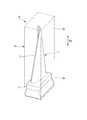
本実施形態で扱う長尺物は、図7に示すように、翼1、この翼1を形成するための金属製の翼素材1a、及びこの翼素材1aから翼1を形成する過程の翼中間品1b(図2参照)である。これら翼素材1a、翼中間品1bは、いずれも一方向に長い物である。なお、以下では、翼1、翼素材1a及び翼中間品1bを総称して、翼形成品1dとする。
まず、本実施形態で扱う長尺物について説明する。
本実施形態で扱う長尺物は、図7に示すように、翼1、この翼1を形成するための金属製の翼素材1a、及びこの翼素材1aから翼1を形成する過程の翼中間品1b(図2参照)である。これら翼素材1a、翼中間品1bは、いずれも一方向に長い物である。なお、以下では、翼1、翼素材1a及び翼中間品1bを総称して、翼形成品1dとする。
翼1は、一方向である長手方向Dwに長い翼体2と、この翼体2の長手方向Dwにおける端部に設けられている翼根3と、を有する。翼体2の表面は三次元曲面を成している。翼根3は、例えば、回転機械のロータ軸に固定される部分で、言い換えると翼固定部である。なお、本願では、翼1をある部材に固定する翼1の一部を翼根としている。このため、例えば、回転機械のケーシングに翼1を固定する部分も、本願では翼根として扱う。翼素材1aは、その外形が翼1の外形よりも大きい直方体形状を成している。
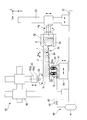
翼素材1aを翼1に加工する加工装置Mは、図1及び図2に示すように、翼形成品1dを支持する支持具10と、この支持具10に駆動用の流体を供給する流体供給器40、と、翼素材1aを加工する加工機50と、流体供給器40や加工機50を制御する制御装置(図示されていない)を備えている。ここで、鉛直方向をZ方向、Z方向に対して垂直な方向をY方向、Z方向及びY方向に垂直な方向をX方向とする。
加工機50は、ベース51と、ワーク把持機52と、把持機移動機構53と、支持具移動機構54と、工具駆動機構55と、工具移動機構56と、を有する。ワーク把持機52は、翼形成品1dの長手方向Dwにおける端部を把持する。把持機移動機構53は、ベース51に対してワーク把持機52を相対移動させる。支持具移動機構54は、ベース51に対して支持具10を相対移動させる。工具駆動機構55は、翼素材1aを加工する加工工具を駆動する。工具移動機構56は、工具駆動機構55で少なくとも加工工具が装着される部分をベース51に対して相対移動させる。
把持機移動機構53は、ベース51に対してワーク把持機52を、X方向、Y方向、Z方向、さらにY方向の延びるワーク把持機52の把持軸Agを基準にした周方向に、少なくとも相対移動させる。支持具移動機構54は、ベース51に対して支持具10を、X方向、Y方向、Z方向に、少なくとも相対移動させる。工具駆動機構55は、円板又は円柱状の加工工具59が装着されるスピンドル55sと、このスピンドル55sを回転させるスピンドル回転機構55dと、を有する。工具移動機構56は、ベース51に対して工具駆動機構55中の少なくともスピンドル55sを、X方向、Y方向、Z方向に、少なくとも相対移動させる。
流体供給器40は、一定圧以上の圧力の流体を吐出する流体吐出源41と、流体吐出源41からの流体を支持具10に導く流体ライン42と、この流体ライン42中に設けられている流体調節弁43と、を有する。なお、流体吐出源41が吐出する流体としては、空気等の気体でも、油等の液体でもよい。
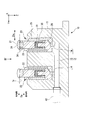
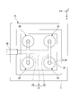
支持具10は、図3及び図4に示すように、複数のサポートシリンダ20と、複数のサポートシリンダ20が取り付けられているシリンダ台11と、を有する。この例では、4つのサポートシリンダ20がシリンダ台11に取り付けられている。
サポートシリンダ20は、ピン21と、ケーシング25と、追従機構31と、ピン拘束機構35と、を有する。ケーシング25は、ピン21が延びているピン延在方向Dpに変位可能にピン21の基端部を覆う。追従機構31は、ピン延在方向Dpにおける翼形成品1dの表面位置の移動にピン延在方向Dpにおけるピン21の位置を追従させる。ピン拘束機構35は、ケーシング25に対するピン21のピン延在方向Dpにおける相対位置を拘束する。ここで、ピン延在方向Dpの一方側を先端側、この反対側を基端側とする。
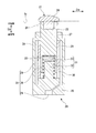
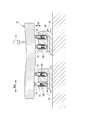
ケーシング25には、図5に示すように、ピン21の基端側の部分であるピン基端部と、追従機構31と、ピン拘束機構35とが配置されると共に、流体供給器40からの流体が流入するシリンダ室26が形成されている。ケーシング25には、シリンダ室26内からピン延在方向Dpに貫通してピン21が挿入されるピン孔27と、シリンダ室26内に流体供給器40からの流体を受け入れる流入口28とが形成されている。
ピン21は、ピン延在方向Dpに延びる軸を中心として円筒状を成すピン本体22と、翼形成品1dに接する接触座24と、を有する。ピン本体22には、基端側から先端側に向かって凹む円柱状の穴23が形成されている。接触座24は、ピン延在方向Dpにおけるピン本体22の先端側に固定されている。この接触座24は、ピン延在方向Dpにおける先端側の開口を塞ぐ。よって、この接触座24は、ピン21の先端部を形成する。
追従機構31は、ガイドロッド32と、弾性部材としてのバネ33と、を有する。ガイドロッド32は、ピン延在方向Dpにおけるピン21の移動をガイドする。バネ33は、ピン21をピン延在方向Dpであってケーシング25から突出する側に付勢する。ガイドロッド32は、円柱状を成し、ケーシング25の基端側を形成する底部からシリンダ室26内をピン延在方向Dpに延びている。このガイドロッド32の先端側の部分は、ピン本体22の穴23内に挿入されている。バネ33は、ピン本体22の穴23内であってガイドロッド32と穴23の底面との間に配置されている。このバネ33は、ピン21が最大突出位置に位置しているときでも、ピン本体22及びガイドロッド32に接している。バネ33は、最大突出位置に位置しているピン21に対して、ピン延在方向Dpにおける基端側を向く荷重がかかると縮み、ピン延在方向Dpにおける先端側に付勢力を発生する。
ピン21の基端部の外周は、円筒状のコレット36で覆われている。このコレット36は、外周側から内周側に向かって弾性変形可能に形成されている。このコレット36の外周側とケーシング25の内周面との間は、流体供給器40からの流体が流入する流体室29を形成している。ピン拘束機構35は、コレット36と、ケーシング25内の流体室29と、ケーシング25に形成されている流入口28とで構成されている。ケーシング25の流入口28から流体室29に、一定圧力の流体が供給されると、この流体の圧力により、コレット36が内周側に向かって弾性変形し、ピン21の基端部を把持する。このコレット36によるピン21の把持により、ピン21は、ピン延在方向Dpに移動不能に拘束される。すなわち、このコレット36は、ピン把持部材を構成する。
シリンダ台11には、図3及び図4に示すように、複数のサポートシリンダ20の各ケーシング25が埋め込まれて固定されている。複数のサポートシリンダ20の各ピン21におけるピン延在方向Dpは、シリンダ台11にケーシング25が固定されている状態で、互いに揃っている。つまり、各ピン21におけるピン延在方向Dpは、同じ方向である。なお、各ピン21におけるピン延在方向Dpは、同じ方向でなくてもよい。さらに、複数のサポートシリンダ20の各ピン21のピン延在方向Dpにおける位置は、各ピン21が最大突出位置に位置している状態で、互いに同じである。
シリンダ台11には、流体供給器40の流体ライン42からの流体を受け入れて、複数のサポートシリンダ20における各ケーシング25の流入口28に流体を導く流路12が形成されている。この流路12は、流体供給器40の流体ライン42に接続されている。この流路12は、主流路13と、複数の分岐流路14と、を有する。主流路13は、流体ライン42からの流体を受け入れる。分岐流路14は、主流路13から複数のサポートシリンダ20毎に分岐して各ケーシング25の流入口28に接続されている。このため、シリンダ台11に接続される流体ライン42を、複数のサポートシリンダ20毎に設ける必要が無く、この流体ライン42を統合化できる。
なお、支持装置は、以上で説明した加工装置Mの構成要素のうち、支持具10、支持具移動機構54、ワーク把持機52、把持機移動機構53、及びベース51により構成されている。
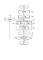
次に、以上で説明した加工装置Mを用いて、翼素材1aを翼1に加工する加工手順について、図6に示すフローチャートに従って説明する。
まず、図1に示すように、支持具10をベース51上の所定位置に配置する(S1:初期準備工程)。この初期準備工程(S1)では、支持具10を加工機50の支持具移動機構54に固定する。次に、支持具移動機構54を駆動し、後述の加工工程(S7)で翼素材1aを加工している際に、支持具10における複数のピン21の全てが翼素材1aに接触し得る所定位置に、この支持具10を配置する。支持具10が所定位置に配置されると、本実施形態において、複数のサポートシリンダ20の各ピン21のピン延在方向Dpは、Z方向、つまり鉛直方向になる。
次に、翼素材1aを加工機50のワーク把持機52で把持する(S2:ワーク把持工程)。このワーク把持工程(S2)では、翼素材1aの長手方向Dwの端部であって、翼根(翼固定部)3となる翼根形成部(翼固定形成部)3aを把持する。
次に、把持機移動機構53を駆動し、ワーク把持機52と共に、このワーク把持機52で把持されている翼素材1aを後述の加工工程(S7)で加工する所定位置に配置する(S4:ワーク配置工程)。翼素材1aが所定位置に配置されると、本実施形態において、翼素材1aの長手方向Dwは、Y方向になる。つまり、翼素材1aの長手方向Dwは、Z方向に垂直な水平方向になり、所定位置に配置された支持具10における各ピン21のピン延在方向Dpに対して垂直な方向になる。
このワーク配置工程(S4)の過程で、翼素材1a中で翼体2となる翼体形成部2aにおける下向きの表面には、複数のピン21の各接触座24が順次接する。ピン21の接触座24が翼素材1aの表面に接すると、サポートシリンダ20の追従機構31により、ピン延在方向Dpにおける翼素材1aの表面の位置の移動に、ピン延在方向Dpにおけるピン21の位置が追従する(S5:ピン追従工程)。このピン追従工程(S5)中、ピン21の接触座24は翼素材1aの表面に接触し続ける。
ワーク配置工程(S4)の完了後、流体供給器40から支持具10に流体を供給する。
この流体は、シリンダ台11の主流路13及び分岐流路14を経て、複数のサポートシリンダ20の流体室29内に流入し、コレット36を内周側に弾性変形させる。この結果、コレット36は、ピン21の基端部を把持し、ピン21をピン延在方向Dpへ移動不能に拘束する(S6:ピン拘束工程)。
この流体は、シリンダ台11の主流路13及び分岐流路14を経て、複数のサポートシリンダ20の流体室29内に流入し、コレット36を内周側に弾性変形させる。この結果、コレット36は、ピン21の基端部を把持し、ピン21をピン延在方向Dpへ移動不能に拘束する(S6:ピン拘束工程)。
翼素材1aを支持する支持工程(S3)では、以上で説明したワーク配置工程(S4)、ピン追従工程(S5)及びピン拘束工程(S6)が実行される。この支持工程(S3)では、翼体形成部2aにおける下向きの表面に、支持具10における全てのピン21の接触座24が接して、この支持具10が翼素材1aを下方から支持する。
支持工程(S3)の完了後、スピンドル55sに加工工具59が装着されている工具駆動機構55を駆動して、加工工具59を回転させると共に、工具移動機構56を駆動して、翼素材1a中の翼体形成部2aにおける上側の部分を加工する(S7:加工工程(S7))。
この加工工程(S7)中、翼素材1aは、ワーク把持機52で把持されつつ、支持具10で支持されている。加工工程(S7)中、支持具10を一切に移動させなくてもよいが、移動させてもよい。例えば、加工中における加工工具59の移動過程で、加工工具59と支持具10とがピン延在方向Dpで対向しなくなると、両者が対向するように支持具10を移動させてもよい。この際、加工工具59の移動を停止し、一旦加工を中止すると共に、支持具10のピン拘束を解除してから、加工工具59と対向するよう支持具10を移動させる。その後、支持具10のピン21を拘束してから、再び、加工工具59による加工を開始する。
この加工工程(S7)の完了で、翼素材1a中の翼体形成部2aにおける上側の部分が加工される。上側の部分が加工された翼素材1aは、翼中間品1b(図2参照)となる。
次に、翼中間品1b中の翼体形成部2aにおける下側の部分を加工するために、中間準備工程(S9)を実行する。この中間準備工程(S9)では、把持機移動機構53を駆動し、ワーク把持機52と共に、このワーク把持機52で把持されている翼中間品1bを上方に移動させて、支持具10と翼中間品1bとを離す。支持具10と翼中間品1bとが離れると、支持具10のピン拘束を解除する。次に、把持機移動機構53をさらに駆動し、ワーク把持機52と共に、このワーク把持機52で把持されている翼中間品1bを、ワーク把持機52の把持軸Agを中心として反転させる。この結果、翼中間品1b中で下側の部分が上側の部分になり、上側の部分が下側の部分になる。次に、支持具移動機構54を駆動し、翼中間品1b中で上側の部分になった未加工部分の加工に適切な所定位置に翼中間品1bを位置させた際、支持具10における複数のピン21が翼中間品1bの下面に接触し得る位置に支持具10を移動させる。以上で中間準備工程(S9)が完了する。
中間準備工程(S9)が完了すると、図2に示すように、前述の支持工程(S3)を実行する。すなわち、把持機移動機構53を駆動し、ワーク把持機52と共に、このワーク把持機52で把持されている翼中間品1bをこの後の加工工程(S7)で加工する所定位置に配置する(S4:ワーク配置工程)。このワーク配置工程(S4)でも、本実施形態において、翼中間品1bの長手方向DwはY方向になる。
このワーク配置工程(S4)の過程で、翼中間品1b中で翼体2となる翼体形成部2aにおける下向きの表面には、複数のピン21の各接触座24が順次接する。このワーク配置工程(S4)の過程でも、ピン21の接触座24が翼素材1aの表面に接すると、サポートシリンダ20の追従機構31により、ピン延在方向Dpにおける翼素材1aの表面の位置の移動に、ピン延在方向Dpにおけるピン21の位置が追従する(S5:ピン追従工程)。翼中間品1b中の翼体形成部2aにおける下向きの表面は、既に加工してある面であるため、三次元曲面を成している。しかしながら、このピン追従工程(S5)の実行で、複数のピン21の接触座24の全ては、翼中間品1bの下向きの表面に接触する。ワーク配置工程(S4)の完了後、流体供給器40から支持具10に流体を供給し、支持具10における複数のピン21の全てをピン延在方向Dpへ移動不能に拘束する(S6:ピン拘束工程)。
支持工程(S3)の完了後、工具駆動機構55を駆動して、加工工具59を回転させると共に、工具移動機構56を駆動して、翼素材1a中の翼体形成部2aにおける上側の部分を加工する(S7:加工工程(S7))。
この加工工程(S7)の完了で、翼体2の加工が完了すれば(S8でYES)、一連の処理が終了する。なお、以上の加工が粗加工であり、さらに仕上加工を行う場合には、再び、中間準備工程(S9)を経て、支持工程(S3)、加工工程(S7)を実行する。中間準備工程(S9)では、必要に応じて、加工工具59を交換する。
以上、本実施形態の支持具10は、複数のサポートシリンダ20のそれぞれが追従機構31を有しているため、翼形成品1d等の長尺物の表面が曲面を成している場合や、長尺物の表面に複数の凹凸が形成されている場合でも、長尺物の表面に複数のピン21を接触させることができる。また、本実施形態の支持具10は、複数のサポートシリンダ20のそれぞれがピン拘束機構35を有しているため、長尺物の表面に全てのピン21が接触している状態で、ピン21の移動を拘束することができる。このため、本実施形態の支持具10は、翼形成品1d等の長尺物を安定支持することができる。
しかも、本実施形態では、加工工程(S7)中、支持具10で翼体形成部2aを支持しつつも、翼形成品1dの長手方向Dwの端部である翼根形成部3aをワーク把持機52で把持しているので、翼形成品1dの全体を極めて安定支持することができる。
このため、本実施形態では、加工中における加工部分のビビリ振動(Chatter Vibration)を抑えることができる。この結果、本実施形態では、ビビリ振動に伴う、加工済み面の表面粗さの荒れ、加工工具59の損傷等を抑えることができる。
なお、上記実施形態では、初期準備工程(S1)完了後及び中間準備工程(S9)完了後における各ピン21のピン延在方向Dpが鉛直方向になる。しかしながら、これは一例であり、初期準備工程(S1)完了後及び中間準備工程(S9)完了後における各ピン21のピン延在方向Dpは、他の方向になってもよい。また、上記実施形態では、ワーク配置工程(S4)完了後の翼形成品1dの長手方向Dwは、ピン延在方向Dpに対して垂直な方向である。しかしながら、ワーク配置工程(S4)完了後の翼形成品1dの長手方向Dwは、ピン延在方向Dpに対して垂直な方向成分を有する方向であれば、垂直な方向でなくてもよい。
また、上記実施形態では、翼形成品1d中の翼体形成部2aを加工する際、翼形成品1d中で未加工の翼根形成部3aを把持している。しかしながら、翼形成品1d中の翼体形成部2aを加工する際、加工完了後の翼根3を把持してもよい。
また、上記実施形態では、翼素材1aから翼1を加工する例である。しかしながら、長尺物であれば、この例に限定されない。
「第二実施形態」
上記第一実施形態は、長尺物の加工に際して支持具10を用いる例である。本実施形態では、長尺物の検査に際して支持具10を用いる例である。
上記第一実施形態は、長尺物の加工に際して支持具10を用いる例である。本実施形態では、長尺物の検査に際して支持具10を用いる例である。
本実施形態でも、上記第一実施形態における加工手順と基本的に同様に検査を行う。すなわち、初期準備工程、支持工程、検査工程を行う。さらに、必要に応じて中間準備工程、再度の支持工程、再度の検査工程を行う。また、本実施形態の支持工程でも、上記第一実施形態と同様、ワーク配置工程、ピン追従工程及びピン拘束工程を実行する。
初期準備工程では、図8に示すように、複数の支持具10を一定の方向Dwに並べて配置する。この際、複数の支持具10における各ピン21のピン延在方向Dpは、互いに揃っている。支持工程中のワーク配置工程では、長尺物1cの長手方向Dwが複数の支持具10が並んでいる方向になるよう、長尺物1cを配置する。
本実施形態におけるワーク配置工程の過程でも、長尺物1cの表面に、複数の支持具10の各ピン21が順次接する。ピン21が長尺物1cの表面に接すると、サポートシリンダ20の追従機構31により、ピン延在方向Dpにおける長尺物1cの表面の位置の移動に、ピン延在方向Dpにおけるピン21の位置が追従する(ピン追従工程)。ワーク配置工程の完了後、上記実施形態と同様に、複数の支持具10における各ピン21をピン延在方向Dpへ移動不能に拘束する(ピン拘束工程)。
支持工程の完了後、この長尺物1cに対する検査工程を実行する。検査工程の検査内容としては、例えば、長尺物1cの表面粗さ検査、長尺物1cの形状検査、長尺物1cが溶接部を有するものであれば溶接部の検査等の各種検査がある。例えば、プローブ9を用いる検査の場合、長尺物1cの表面中で、下側の表面を除く部分にプローブ9を接触させる。
以上、本実施形態では、複数の支持具10における複数のピン21の全てが長尺物1cに接した状態で、この長尺物1cを支持することができる。このため、長尺物1cを安定支持することができる。
しかも、本実施形態では、複数の支持具10で長尺物1cを支持するので、長尺物1cの全体を極めて安定支持することができる。
このため、本実施形態では、検査工程で精密な検査をおこなうことができる。
以上のように、長尺物を加工する場合のみならず、長尺物を検査する場合にも、支持具10を用いてもよい。また、例えば、単に長尺物を展示等する場合に、支持具10を用いて、この長尺物を支持してもよい。
本実施形態では、複数の支持具10を用いて長尺物1cを支持している。上記第一実施形態でも、本実施形態と同様に、複数の支持具10を用いて翼形成品1dを支持してもよい。
本発明の一態様によれば、長尺物を安定支持することができる。
1:翼(長尺物)、1a:翼素材(長尺物)、1b:翼中間品(長尺物)、1c:長尺物、1d:翼形成品(長尺物)、2:翼体、2a:翼体形成部、3:翼根(翼固定部)、3a:翼根形成部(翼固定形成部)、10:支持具、11:シリンダ台、12:流路、13:主流路、14:分岐流路、20:サポートシリンダ、21:ピン、22:ピン本体、23:穴、24:接触座(先端部)、25:ケーシング、26:シリンダ室、28:流入口、29:流体室、31:追従機構、32:ガイドロッド、33:バネ、35:ピン拘束機構、36:コレット(ピン把持部材)、40:流体供給器、50:加工機、51:ベース、52:ワーク把持機、53:把持機移動機構、54:支持具移動機構、55:工具駆動機構、56:工具移動機構、M:加工装置
Claims (15)
- 一方向に長い長尺物を支持する支持具において、
前記一方向に対して垂直な方向成分を有する方向から、前記長尺物を支持する複数のシリンダと、
複数のシリンダが取り付けられているシリンダ台と、
を備え、
前記シリンダは、ピンと、前記ピンが延びているピン延在方向に変位可能に前記ピンの基端部を覆うケーシングと、前記ピンの先端側に配置された前記長尺物の表面に前記ピンの先端部が接触するよう、前記ピン延在方向における前記長尺物の表面の位置に前記ピン延在方向における前記ピンの位置を追従させる追従機構と、前記ケーシングに対する前記ピンの前記ピン延在方向における相対位置を拘束するピン拘束機構と、を有し、
複数の前記シリンダのそれぞれの前記ケーシングは、前記シリンダ台に固定されている、
支持具。 - 請求項1に記載の支持具において、
前記追従機構は、前記ケーシング内に配置され、前記ピンを前記ピン延在方向であって前記ケーシングから突出する側に付勢する弾性部材を有する、
支持具。 - 請求項1又は2に記載の支持具において、
前記ピン拘束機構は、前記ケーシング内に配置され、流体圧を受けて変形して前記ピンを把持して、前記ケーシングに対する前記ピンの前記ピン延在方向における相対位置を拘束するピン把持部材を有する、
支持具。 - 請求項3に記載の支持具において、
前記ケーシングには、前記ピン把持部材を変形させる流体を内部に受け入れる流入口が形成され、
前記シリンダ台には、外部からの前記流体を受け入れて、前記ケーシングの前記流入口に前記流体を導く流路が形成されている、
支持具。 - 請求項4に記載の支持具において、
前記流路は、前記流体を外部から受け入れる主流路と、複数の前記シリンダ毎に設けられ、前記主流路から分岐して複数の前記ケーシングの前記流入口に接続されている分岐流路と、を有する、
支持具。 - 請求項1から5のいずれか一項に記載の支持具と、
前記長尺物の前記一方向における端部を把持するワーク把持機と、
前記ワーク把持機の向き及び前記ワーク把持機の位置を変える把持機移動機構と、
を備える支持装置。 - 請求項6に記載の支持装置において、
前記把持機移動機構が取り付けられているベースと、
前記ベースに対して前記支持具を相対移動させる支持具移動機構と、
を備える支持装置。 - 請求項1から5のいずれか一項に記載の支持具と、
前記支持具により支持された前記長尺物を加工する加工工具が装着され、前記加工工具を駆動する工具駆動機構と、
前記工具駆動機構で少なくとも前記加工工具が装着される部分を移動させる工具移動機構と、
を備える加工装置。 - 請求項6又は7に記載の支持装置と、
前記ワーク把持機により把持され且つ前記支持具により支持された前記長尺物を加工する加工工具が装着され、前記加工工具を駆動する工具駆動機構と、
前記工具駆動機構で少なくとも前記加工工具が装着される部分を移動させる工具移動機構と、
を備える加工装置。 - 一方向に長い長尺物を支持する支持方法において、
複数のピンを配置する準備工程と、
前記準備工程で配置された複数の前記ピンの先端部に前記長尺物を接触させて、複数の前記ピンで前記長尺物を支持する支持工程と、
を実行し、
前記準備工程では、前記ピンが延びているピン延在方向が複数の前記ピン相互で揃い、且つ前記支持工程で支持されたときの前記長尺物の前記一方向に対して垂直な方向成分を有する方向を向くよう、複数の前記ピンを配置し、
前記支持工程は、
複数の前記ピンの先端部に前記長尺物が接触するよう、前記長尺物を配置するワーク配置工程と、
前記ワーク配置工程の過程で、前記長尺物の表面に複数の前記ピンの先端部がそれぞれ接触するよう、前記ピン延在方向における前記長尺物の表面の位置に前記ピン延在方向における前記ピンの位置を追従させるピン追従工程と、
前記ワーク配置工程後に、複数の前記ピンの前記ピン延在方向における位置を拘束するピン拘束工程と、
を含む、
支持方法。 - 請求項1から5のいずれか一項に記載の支持具を用いて、前記長尺物を支持方法において、
前記支持具を配置する準備工程と、
前記準備工程で配置された前記支持具における複数の前記ピンの先端部に、前記長尺物を接触させて、複数の前記ピンで前記長尺物を支持する支持工程と、
を実行し、
前記準備工程では、前記ピン延在方向が前記支持工程で支持されたときの前記長尺物の前記一方向に対して垂直な方向成分を有する方向になるよう、前記支持具を配置し、
前記支持工程は、
複数の前記ピンの先端部に前記長尺物が接触するよう、前記長尺物を配置するワーク配置工程と、
前記ワーク配置工程の過程で、前記追従機構により、前記ピン延在方向における前記長尺物の表面の位置に前記ピン延在方向における前記ピンの位置を追従させて、前記長尺物の表面に複数の前記ピンの先端部を接触させるピン追従工程と、
前記ワーク配置工程後に、前記ピン拘束機構により、複数の前記ピンの前記ピン延在方向における位置を拘束するピン拘束工程と、
を含む、
支持方法。 - 請求項10又は11に記載の支持方法により、前記長尺物としての長尺物素材又は長尺物中間品を支持し、
前記支持方法で支持されている前記長尺物素材又は前記長尺物中間品を加工する加工工程を実行する、
加工方法。 - 請求項12に記載の加工方法において、
少なくとも前記加工工程の実行中、前記長尺物素材又は前記長尺物中間品の前記一方向における端部を把持するワーク把持工程を実行する、
加工方法。 - 請求項12又は13に記載の加工方法において、
前記長尺物素材又は前記長尺物中間品は、前記一方向に延びる翼体と、前記翼体の前記一方向における端部に設けられている翼固定部と、を有する翼の翼素材又は翼中間品であり、
前記支持工程では、前記翼素材又は前記翼中間品中で前記翼体となる翼体形成部を複数の前記ピンで支持し、
前記加工工程では、前記翼体形成部であって、複数の前記ピンが接している側とは反対側を含む部分を加工する、
加工方法。 - 請求項13に記載の加工方法において、
前記長尺物素材又は前記長尺物中間品は、前記一方向に延びる翼体と、前記翼体の前記一方向における端部に設けられている翼固定部と、を有する翼の翼素材又は翼中間品であり、
前記支持工程では、前記翼素材又は前記翼中間品中で前記翼体となる翼体形成部を複数の前記ピンで支持し、
前記ワーク把持工程では、前記翼素材又は前記翼中間品中で前記翼固定部となる翼固定形成部又は前記翼固定部を把持し、
前記加工工程では、前記翼体形成部であって、複数の前記ピンが接している側とは反対側を含む部分を加工する、
加工方法。
Priority Applications (2)
| Application Number | Priority Date | Filing Date | Title |
|---|---|---|---|
| KR1020177025795A KR101917555B1 (ko) | 2015-04-08 | 2016-04-06 | 지지 방법, 가공 방법, 및 이러한 방법을 실행하는 장치 |
| CN201680015599.3A CN107427977B (zh) | 2015-04-08 | 2016-04-06 | 支撑件、支撑装置、支撑方法、加工装置及加工方法 |
Applications Claiming Priority (2)
| Application Number | Priority Date | Filing Date | Title |
|---|---|---|---|
| JP2015-079364 | 2015-04-08 | ||
| JP2015079364A JP6312327B2 (ja) | 2015-04-08 | 2015-04-08 | 支持方法、加工方法、及びこれらの方法を実行する装置 |
Publications (1)
| Publication Number | Publication Date |
|---|---|
| WO2016163405A1 true WO2016163405A1 (ja) | 2016-10-13 |
Family
ID=57072254
Family Applications (1)
| Application Number | Title | Priority Date | Filing Date |
|---|---|---|---|
| PCT/JP2016/061276 Ceased WO2016163405A1 (ja) | 2015-04-08 | 2016-04-06 | 支持方法、加工方法、及びこれらの方法を実行する装置 |
Country Status (4)
| Country | Link |
|---|---|
| JP (1) | JP6312327B2 (ja) |
| KR (1) | KR101917555B1 (ja) |
| CN (1) | CN107427977B (ja) |
| WO (1) | WO2016163405A1 (ja) |
Families Citing this family (7)
| Publication number | Priority date | Publication date | Assignee | Title |
|---|---|---|---|---|
| KR102253325B1 (ko) * | 2020-03-03 | 2021-05-18 | 김옥현 | 이젝트핀 헤드 지지 지그, 이를 구비한 이젝트핀 가공 장치, 및 상기 이젝트핀 가공 장치를 이용한 이젝트핀 가공 방법 |
| KR102361572B1 (ko) * | 2021-03-31 | 2022-02-14 | 한전케이피에스 주식회사 | 블레이드 고정 지그 및 이를 포함하는 냉각공 가공 시스템 |
| CN120395483A (zh) * | 2022-09-05 | 2025-08-01 | 株式会社骏河生产Pf | 治具装置和治具单元 |
| JP7360574B1 (ja) | 2022-09-05 | 2023-10-13 | 株式会社駿河生産プラットフォーム | 治具装置、及び治具ユニット |
| JP7373681B1 (ja) | 2022-09-05 | 2023-11-02 | 株式会社駿河生産プラットフォーム | 治具装置、及び治具ユニット |
| CN116475793B (zh) * | 2023-05-05 | 2025-11-14 | 合肥工业大学 | 薄壁圆筒件加工装置 |
| KR102759848B1 (ko) * | 2024-01-09 | 2025-01-24 | 주식회사 비엠메탈 | 소재 재단용 정밀가공장치 |
Citations (8)
| Publication number | Priority date | Publication date | Assignee | Title |
|---|---|---|---|---|
| JPS5330091A (en) * | 1976-08-31 | 1978-03-20 | Toshiba Corp | Swing jack |
| JPS58146634U (ja) * | 1982-03-29 | 1983-10-03 | 株式会社東芝 | 工作物の支持装置 |
| JPH03234434A (ja) * | 1990-02-09 | 1991-10-18 | Suzuki Motor Corp | ワーク位置決め装置 |
| JPH06297222A (ja) * | 1993-04-09 | 1994-10-25 | Hitachi Ltd | 工作物支持装置およびそれを用いた工作機械 |
| JPH07214440A (ja) * | 1994-02-02 | 1995-08-15 | Ohashi Kogyo Kk | ブレード等弾性特性加工品のチャッキング装置 |
| JP2005279793A (ja) * | 2004-03-29 | 2005-10-13 | Institute Of Physical & Chemical Research | 予圧サポートとこれを用いた薄肉部材の超精密加工方法 |
| JP2008030108A (ja) * | 2006-07-31 | 2008-02-14 | Nippei Toyama Corp | レーザ加工機におけるワークの支持装置 |
| US20130269189A1 (en) * | 2010-09-24 | 2013-10-17 | Starragheckert Ag | Method and Device for Machining Elongate Workpieces that are not Rotationally Symmetrical in the Form of Tubine Blades |
Family Cites Families (6)
| Publication number | Priority date | Publication date | Assignee | Title |
|---|---|---|---|---|
| CN2548811Y (zh) * | 2001-08-24 | 2003-05-07 | 中山市富山玻璃机械有限公司 | 数控玻璃雕刻机的磨头座的快速换刀机构 |
| CN201677197U (zh) * | 2010-04-29 | 2010-12-22 | 三门峡上阳电器平衡机械有限公司 | 浮动夹紧装置 |
| JP5216075B2 (ja) * | 2010-12-22 | 2013-06-19 | Towa株式会社 | ブレード着脱装置 |
| JP3172627U (ja) * | 2011-10-07 | 2012-01-05 | 伊藤 幸男 | タービンブレードの両端把持装置 |
| CN202742070U (zh) * | 2012-08-13 | 2013-02-20 | 高晓萍 | 立式加工中心液压夹具 |
| CN103737353B (zh) * | 2013-12-19 | 2016-06-15 | 东方电气集团东方汽轮机有限公司 | 一种用于汽道加工的汽轮机叶片定位装夹系统 |
-
2015
- 2015-04-08 JP JP2015079364A patent/JP6312327B2/ja active Active
-
2016
- 2016-04-06 CN CN201680015599.3A patent/CN107427977B/zh active Active
- 2016-04-06 WO PCT/JP2016/061276 patent/WO2016163405A1/ja not_active Ceased
- 2016-04-06 KR KR1020177025795A patent/KR101917555B1/ko active Active
Patent Citations (8)
| Publication number | Priority date | Publication date | Assignee | Title |
|---|---|---|---|---|
| JPS5330091A (en) * | 1976-08-31 | 1978-03-20 | Toshiba Corp | Swing jack |
| JPS58146634U (ja) * | 1982-03-29 | 1983-10-03 | 株式会社東芝 | 工作物の支持装置 |
| JPH03234434A (ja) * | 1990-02-09 | 1991-10-18 | Suzuki Motor Corp | ワーク位置決め装置 |
| JPH06297222A (ja) * | 1993-04-09 | 1994-10-25 | Hitachi Ltd | 工作物支持装置およびそれを用いた工作機械 |
| JPH07214440A (ja) * | 1994-02-02 | 1995-08-15 | Ohashi Kogyo Kk | ブレード等弾性特性加工品のチャッキング装置 |
| JP2005279793A (ja) * | 2004-03-29 | 2005-10-13 | Institute Of Physical & Chemical Research | 予圧サポートとこれを用いた薄肉部材の超精密加工方法 |
| JP2008030108A (ja) * | 2006-07-31 | 2008-02-14 | Nippei Toyama Corp | レーザ加工機におけるワークの支持装置 |
| US20130269189A1 (en) * | 2010-09-24 | 2013-10-17 | Starragheckert Ag | Method and Device for Machining Elongate Workpieces that are not Rotationally Symmetrical in the Form of Tubine Blades |
Also Published As
| Publication number | Publication date |
|---|---|
| CN107427977A (zh) | 2017-12-01 |
| JP2016198835A (ja) | 2016-12-01 |
| JP6312327B2 (ja) | 2018-04-18 |
| CN107427977B (zh) | 2020-08-25 |
| KR20170117180A (ko) | 2017-10-20 |
| KR101917555B1 (ko) | 2018-11-09 |
Similar Documents
| Publication | Publication Date | Title |
|---|---|---|
| JP6312327B2 (ja) | 支持方法、加工方法、及びこれらの方法を実行する装置 | |
| KR102004075B1 (ko) | 날개의 가공 방법, 날개의 가공 장치, 이러한 가공 장치의 가공 순서 제어 프로그램 | |
| JP6774343B2 (ja) | 工作機械 | |
| US9676046B2 (en) | Electrical discharge machining method | |
| JP6487373B2 (ja) | ワーク固定装置 | |
| US10105815B2 (en) | Multiaxial vibration-peening system | |
| US12151326B2 (en) | Machining apparatus | |
| US10556310B2 (en) | Method for cutting machining of turbine blades | |
| KR101396689B1 (ko) | 공작 기계 | |
| US11806794B2 (en) | Processing device and processing method | |
| TW202033293A (zh) | 工作機械以及控制裝置 | |
| JP2016132091A5 (ja) | ||
| US20130287511A1 (en) | Centering method and apparatus | |
| JP7103136B2 (ja) | 工作機械及び加工方法 | |
| JP2017035752A (ja) | 被加工物の振動を抑制する振動抑制方法及び機械加工システム | |
| JP5423411B2 (ja) | 旋削装置および旋削方法 | |
| CN105666258B (zh) | 数控磨削加工方法和装置 | |
| JP2009274171A (ja) | チャック機構およびそのチャック機構を用いたワーク搬送装置 | |
| JP7013195B2 (ja) | 仕上げ加工方法 | |
| TW201711787A (zh) | 工具機之夾持裝置 | |
| JP5978120B2 (ja) | 加工装置 | |
| KR20200012472A (ko) | 다축 가공기 | |
| JP2014104564A (ja) | センタリング方法及び装置 | |
| JP6175082B2 (ja) | 機械部品の製造方法、機械部品の製造装置、回転対称面の加工方法、記録媒体およびプログラム | |
| JP6405115B2 (ja) | 孔加工方法、シリンダブロックの製造方法および孔加工機 |
Legal Events
| Date | Code | Title | Description |
|---|---|---|---|
| 121 | Ep: the epo has been informed by wipo that ep was designated in this application |
Ref document number: 16776571 Country of ref document: EP Kind code of ref document: A1 |
|
| ENP | Entry into the national phase |
Ref document number: 20177025795 Country of ref document: KR Kind code of ref document: A |
|
| NENP | Non-entry into the national phase |
Ref country code: DE |
|
| 122 | Ep: pct application non-entry in european phase |
Ref document number: 16776571 Country of ref document: EP Kind code of ref document: A1 |