WO2016163301A1 - モータ駆動装置及び3相ブラシレスモータの相電流検出方法 - Google Patents
モータ駆動装置及び3相ブラシレスモータの相電流検出方法 Download PDFInfo
- Publication number
- WO2016163301A1 WO2016163301A1 PCT/JP2016/060699 JP2016060699W WO2016163301A1 WO 2016163301 A1 WO2016163301 A1 WO 2016163301A1 JP 2016060699 W JP2016060699 W JP 2016060699W WO 2016163301 A1 WO2016163301 A1 WO 2016163301A1
- Authority
- WO
- WIPO (PCT)
- Prior art keywords
- phase
- current
- value
- phase current
- motor
- Prior art date
- Legal status (The legal status is an assumption and is not a legal conclusion. Google has not performed a legal analysis and makes no representation as to the accuracy of the status listed.)
- Ceased
Links
Images





Classifications
-
- H—ELECTRICITY
- H02—GENERATION; CONVERSION OR DISTRIBUTION OF ELECTRIC POWER
- H02P—CONTROL OR REGULATION OF ELECTRIC MOTORS, ELECTRIC GENERATORS OR DYNAMO-ELECTRIC CONVERTERS; CONTROLLING TRANSFORMERS, REACTORS OR CHOKE COILS
- H02P6/00—Arrangements for controlling synchronous motors or other dynamo-electric motors using electronic commutation dependent on the rotor position; Electronic commutators therefor
- H02P6/10—Arrangements for controlling torque ripple, e.g. providing reduced torque ripple
-
- H—ELECTRICITY
- H02—GENERATION; CONVERSION OR DISTRIBUTION OF ELECTRIC POWER
- H02P—CONTROL OR REGULATION OF ELECTRIC MOTORS, ELECTRIC GENERATORS OR DYNAMO-ELECTRIC CONVERTERS; CONTROLLING TRANSFORMERS, REACTORS OR CHOKE COILS
- H02P6/00—Arrangements for controlling synchronous motors or other dynamo-electric motors using electronic commutation dependent on the rotor position; Electronic commutators therefor
- H02P6/28—Arrangements for controlling current
-
- H—ELECTRICITY
- H02—GENERATION; CONVERSION OR DISTRIBUTION OF ELECTRIC POWER
- H02P—CONTROL OR REGULATION OF ELECTRIC MOTORS, ELECTRIC GENERATORS OR DYNAMO-ELECTRIC CONVERTERS; CONTROLLING TRANSFORMERS, REACTORS OR CHOKE COILS
- H02P21/00—Arrangements or methods for the control of electric machines by vector control, e.g. by control of field orientation
- H02P21/24—Vector control not involving the use of rotor position or rotor speed sensors
-
- H—ELECTRICITY
- H02—GENERATION; CONVERSION OR DISTRIBUTION OF ELECTRIC POWER
- H02P—CONTROL OR REGULATION OF ELECTRIC MOTORS, ELECTRIC GENERATORS OR DYNAMO-ELECTRIC CONVERTERS; CONTROLLING TRANSFORMERS, REACTORS OR CHOKE COILS
- H02P6/00—Arrangements for controlling synchronous motors or other dynamo-electric motors using electronic commutation dependent on the rotor position; Electronic commutators therefor
- H02P6/14—Electronic commutators
- H02P6/16—Circuit arrangements for detecting position
- H02P6/18—Circuit arrangements for detecting position without separate position detecting elements
Definitions
- the present invention relates to a motor drive device and a phase current detection method for a three-phase brushless motor, and more specifically, detects phase currents of a three-phase brushless motor from current detection values of a current detector that detects a DC bus current of an inverter.
- a current detector that detects a DC bus current of an inverter.
- Patent Document 1 as a current detection method for a converter that converts a direct current into a three-phase alternating current, two current values having different phases are respectively detected by a direct current detector, and two detected current values are used. A method of calculating the current value of the remaining phase is disclosed.
- a motor drive provided with a current detector for detecting a DC bus current of an inverter
- two current detection sections are set in one PWM carrier cycle, and two current values detected in these two sections are three-phased If the current value of the remaining one phase is calculated based on the fact that the sum of the three phase currents becomes zero, the detected value of the DC bus current is calculated from the detected values of the three phases.
- the current can be detected.
- two current detection sections are set in one PWM carrier cycle, and the microcomputer A / D converts and reads the output signal of the current detector in each of the two current detection sections, and reads in each current detection section.
- Two current detection values are assigned to two phases, and the remaining one phase phase current is estimated from the two current detection values to detect three phase currents for each PWM carrier cycle.
- the number of A / D conversions that can be performed in one PWM carrier cycle may be limited to one. There is a problem that the current detection method can not be applied.
- the present invention has been made in view of the above problems, and can detect each phase current by one A / D conversion per PWM carrier cycle using a current detector that detects a DC bus current of an inverter.
- An object of the present invention is to provide a motor drive device and a phase current detection method for a three-phase brushless motor.
- the motor drive device comprises: an inverter that supplies AC power to a three-phase brushless motor; a current detector that detects a DC bus current of the inverter; and an output of the current detector to receive the inverter.
- a control unit that performs PWM control, and drives the three-phase brushless motor in a sine wave manner, and the control unit is configured to calculate an absolute value of a phase current at one detection timing in one cycle of PWM control.
- the maximum phase current of one phase is obtained from the output of the current detector, and the remaining two phases based on the peak value of the phase current detected at each detection timing, the motor angle, and the phase shift of the real phase current waveform with respect to the motor angle.
- phase current detection is performed to detect a phase current of each phase of a three-phase brushless motor sinusoidally driven by PWM control of an inverter and a DC bus current of the inverter.
- the motor drive device and the phase current detection method of the three-phase brushless motor according to the present invention can be applied to a microcomputer in which the number of A / D conversions that can be implemented in one PWM carrier cycle is limited to one.
- FIG. 1 is a block diagram of a hydraulic mechanism of an automatic transmission for a vehicle according to an embodiment of the present invention.
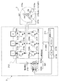
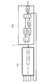
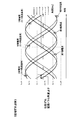
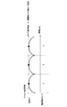
- FIG. 1 is a circuit diagram of a drive circuit and a three-phase brushless motor in an embodiment of the present invention. It is a functional block diagram of PWM control of the three-phase brushless motor in the embodiment of the present invention. It is a functional block diagram showing arithmetic processing of a motor angle in an embodiment of the present invention. It is a time chart which shows the control timing of the switching element of the inverter in embodiment of this invention, and A / D conversion timing of the detection output of an electric current. It is a time chart which illustrates the phase shift to the motor angle of the real phase current of each phase in the embodiment of the present invention.
- the hydraulic mechanism shown in FIG. 1 is an oil pump for supplying oil to the transmission mechanism 7 and the actuator 8 and is a main oil pump 6 driven by the output of the internal combustion engine 12 which is a power source of the vehicle, and an electric sub oil pump And 1.
- the sub oil pump 1 supplies the oil instead of the main oil pump 6 when, for example, the internal oil engine 12 is temporarily stopped by idle stop control or the like and the main oil pump 6 is stopped, or the main oil pump 6 It is driven to perform oil supply supplementarily while driving.
- the sub oil pump 1 is driven by a three phase brushless motor (embedded magnet three phase synchronous motor IPMSM) 2, and the three phase brushless motor 2 is controlled by a motor driving device (MCU) 3.
- the motor drive device 3 drives and controls the three-phase brushless motor 2 based on a command from the AT control device (ATCU) 4.
- the sub oil pump 1 driven by the three-phase brushless motor 2 sucks the oil of the oil pan 10 and supplies it to the transmission mechanism 7 and the actuator 8 through the oil pipe 5.
- the main oil pump 6 driven by the internal combustion engine 12 sucks the oil of the oil pan 10 and supplies it to the transmission mechanism 7 and the actuator 8 through the oil pipe 9.
- the oil supplied to the speed change mechanism 7 and the actuator 8 is returned to the oil pan 10, is again sucked by the sub oil pump 1 and / or the main oil pump 6, and circulates an oil closed circuit.
- a check valve 11 is disposed in the oil pipe 5 on the downstream side of the sub oil pump 1.
- the above-described hydraulic mechanism is an example of a vehicle system using a three-phase brushless motor
- various vehicle systems using a three-phase brushless motor as an actuator include the motor drive device according to the present invention and the three-phase brushless motor
- a current detection method can be applied.
- the motor drive device according to the present invention and the phase current detection method of the three-phase brushless motor are applied to a three-phase brushless motor for driving an electric water pump used for circulating cooling water of internal combustion engine 12 in a hybrid vehicle or the like. be able to.
- FIG. 2 is a circuit diagram showing an example of the three-phase brushless motor 2 and the motor drive device 3.
- the motor drive device 3 for driving the three-phase brushless motor 2 includes a drive circuit (inverter circuit) 212 and a control unit 213.
- the control unit 213 includes an A / D converter 213 a and a microcomputer 213 b configured to include a microprocessor (CPU, MPU, etc.), a ROM, a RAM, and the like, and communicates with the AT control device 4. .
- the three-phase brushless motor 2 is a three-phase DC brushless motor, and is provided with star-connected U-phase, V-phase and W-phase three-phase windings 215u, 215v, 215w in a cylindrical stator not shown;
- a permanent magnet rotor (rotor) 216 is rotatably provided in a space formed at a central portion of the stator.
- the three-phase brushless motor 2 does not have a sensor that detects rotor position information, and the control unit 213 performs drive control of the brushless motor 2 by a sensorless drive method that does not use a sensor that detects rotor position information. .
- the drive circuit 212 includes an inverter 212 a in which switching elements 217 a to 217 f including reverse-parallel diodes 218 a to 218 f are bridge-connected in three phases, and a DC power supply circuit 219. Supply AC power.
- the switching elements 217a to 217f of the inverter 212a are formed of, for example, FETs, and control terminals (gate terminals) of the switching elements 217a to 217f are connected to the control unit 213.
- the control unit (control unit) 213 controls the inverter 212 a in pulse width modulation (PWM). Specifically, the control unit 213 controls the on / off of the switching elements 217a to 217f by PWM of the triangular wave comparison method to control the voltage applied to the three-phase brushless motor 2.
- PWM control of the triangular wave comparison method the timing at which each of the switching elements 217a to 217f is turned on and off is compared by comparing the triangular wave (carrier) with the PWM timer set according to the command duty ratio (command voltage). To detect.
- a current detector 220 for detecting a DC bus current of the inverter 212 a is provided between the lower arm (switching element 217 b, 217 d, 217 f) of each phase and the power supply circuit 219.
- the current detector 220 includes a shunt resistor 220a connected in series between the lower arm of each phase and the power supply circuit 219, and a detection circuit 220b.
- the detection circuit 220b detects a voltage proportional to the current generated by the resistance of the shunt resistor 220a, and outputs an analog signal of the voltage.
- the voltage analog signal (detection signal of DC bus current) of the detection circuit 220b is A / D converted by the A / D converter 213a and read into the microcomputer 213b.
- the control unit 213 drives the brushless motor 2 by a sine wave drive method of applying a sine wave voltage to each phase.
- the control unit 213 obtains positional information of the rotor from an induced voltage (speed electromotive voltage) generated by rotation of the rotor, while the detection period of the rotor position by the speed electromotive voltage.
- the rotor position is estimated based on the motor rotational speed.
- the control unit 213 determines three-phase voltages Vu, Vv, Vw by the vector control method based on the estimated rotor position and the command torque according to the target rotational speed of the sub oil pump 1, etc. Control the direction and strength of the current to flow a three-phase alternating current to each phase.
- the three-phase brushless motor 2 includes a magnetic pole position sensor, and the control unit 213 can drive-control the three-phase brushless motor 2 by detecting the rotor angle (magnetic pole position) based on the output of the magnetic pole position sensor. .
- FIG. 3 is a functional block diagram for explaining setting processing of three-phase voltages Vu, Vv, Vw in the vector control method in the control unit 213.
- a three-phase current detection unit 501 detects the phase current of each of the three phases based on the A / D converted value (the DC bus current of the inverter 212a) of the output of the detection circuit 220b.
- the angle / angular velocity calculation unit 502 estimates a motor angle (magnetic pole position) and an angular velocity (motor rotation number).
- the angle and angular velocity calculation unit 502 includes an axis error estimation unit 651 and a position and velocity estimation unit 652, as shown in FIG.
- the axis error estimation unit 651 receives the d-axis current detection value Idc, the q-axis current detection value Iqc, the d-axis input voltage Vd, the q-axis input voltage Vq, and the motor rotational speed ⁇ . Then, the axis error estimation unit 651 calculates the axis error ⁇ c according to Equation 1.
- Rd is d-axis resistance
- Rq is q-axis resistance
- Ld is d-axis inductance
- Lq is q-axis inductance.
- the position / speed estimation unit 652 calculates the motor angle (magnetic pole position) ⁇ based on the axis error ⁇ c (position estimation error).
- the position / speed estimation unit 652 calculates the value obtained by multiplying the difference between the axis error ⁇ c and the reference value by the proportional gain, and the integral value of the value obtained by multiplying the difference between the axis error ⁇ c and the reference value by the integration gain.
- the sum is integrated, and the sum is integrated to obtain a motor angle (magnetic pole position) ⁇ .
- the control unit 213 can determine that the three-phase brushless motor 2 is out of step.
- the angle / angular velocity calculation unit 502 detects a motor angle (magnetic pole position) and an angular velocity (motor rotation number) based on the output of the magnetic pole position sensor.
- the detected value of the three-phase current by the three-phase current detection unit 501 is based on the motor angle (magnetic pole position) ⁇ at that time. Convert to the current Id, Iq of the -q coordinate system).
- the vector control unit 504 obtains the target current (d-axis command current, q-axis command current) according to the command torque, the angular velocity calculated by the angle / angular velocity calculation unit 502, and the three-phase to two-axis converter 503.
- the currents Id and Iq are input.
- the vector control unit 504 calculates the d-axis current command value Idref and the q-axis current command value Iqref in the dq coordinate system based on the target current and the angular velocity, and the d-axis current command value Idref and the q-axis current command value Command voltages Vq and Vd are determined based on a comparison between Iqref and actual currents Id and Iq obtained by the 3-phase to 2-axis converter 503.
- Two-axis to three-phase converter 505 converts command voltages Vq and Vd into three-phase voltages Vu, Vv and Vw and outputs them.
- PWM modulator 506 outputs three-phase voltages Vu, Vv and Vw as modulation waves.
- the switching gate waveform for driving the switching element of the inverter 212a is generated by comparing with the triangular wave carrier.
- Equation 2 is an example of an arithmetic expression of the command voltages Vq and Vd in the vector control unit 504.
- Vd is d-axis input voltage
- Vq is q-axis input voltage
- kpd is d-axis current feedback proportional gain
- kpq is q-axis current feedback proportional gain
- kid is d-axis current feedback integration gain
- kiq is q-axis current Feedback integral gain
- Idc d-axis current detection value
- Iqc q-axis current detection value
- Ld d-axis inductance
- Lq q-axis inductance
- ⁇ motor rotational speed (rad / sec)
- Ke induced voltage constant
- 1 / s indicates the integral.
- the three-phase current detection unit 501 of the control unit 213 detects the three-phase current based on the output of the current detector 220 that detects the DC bus current of the inverter 212a will be described in detail.
- the three-phase current detection unit 501 includes a peak value extraction unit 601, a three-phase current estimated value generation unit 602, and a phase current allocation unit 603.
- the output (voltage analog signal) of the detection circuit 220b of the current detector 220 is A / D converted at one detection timing in one cycle of PWM control as described later, and the peak value extraction unit 601 and phase current allocation unit It is read into 603.
- the peak value extraction unit 601 extracts the peak value of the phase current based on a plurality of current detection values detected in time series, and outputs the peak value to the three-phase current estimated value generation unit 602.
- each phase current of the three-phase brushless motor 2 is controlled to be a sine wave having a phase difference of 120 deg in electrical angle by vector control, a phase shift occurs with respect to the motor angle.
- the current vector angle (motor angle) ⁇ corrected by the phase shift is input, and thereby, estimation operation of the phase current in consideration of the phase shift is performed.
- the current vector angle correction value calculation unit 604 calculates and outputs a current vector angle correction value ⁇ corresponding to the phase shift.
- the current vector angle correction value ⁇ is added to the actual motor angle [deg (electrical angle)] ⁇ ac, and the addition result is input to the three-phase current estimated value generation unit 602 as the final current vector angle (motor angle) ⁇ .
- the three-phase current estimated value generation unit 602 calculates the phase current estimated value of each phase based on the current vector angle (motor angle) ⁇ corrected by the current vector angle correction value ⁇ .
- the current vector angle correction value calculation unit 604 calculates the correction value ⁇ based on the resistance, the motor rotation number, the d-axis voltage, and the q-axis voltage. That is, the current vector angle (motor angle used to calculate the phase current estimated value) is corrected according to the resistance, the motor rotation number, the d-axis voltage, and the q-axis voltage.
- Three-phase phase current estimated values obtained by the three-phase current estimated value generation unit 602 are input to the phase current allocation unit 603, and A / D conversion is performed at one detection timing in one cycle of PWM control.
- the output of the detection circuit 220b of the current detector 220 is input.
- phase current allocation unit 603 uses the current detection value of current detector 220 as the phase current in one of the three phases of three-phase brushless motor 2.
- the phase current estimated value obtained by the three-phase current estimated value generation unit 602 is allocated to the remaining two phases.
- the above-mentioned current detection mode command is a signal for commanding the phase to which the current detection value of the current detector 220 is assigned as the phase current among the three phases.
- the phase current of one of the three phases is detected by the current detector 220, and the phase currents of the other two phases are estimated from the phase currents detected by the current detector 220. And one phase in which the phase current is directly detected by the current detector 220 is sequentially switched in accordance with the current detection mode command.
- the phase current value of each of the three phases specified by the phase current allocation unit 603 is output to the three-phase to two-axis converter 503, and the three-phase to two-axis converter 503 Converting to the currents Id and Iq in the rotational coordinate system (dq coordinate system), the vector control unit 504 performs vector control using the currents Id and Iq.
- the A / D conversion of the output (voltage analog signal) of the detection circuit 220b of the current detector 220 is configured to be performed at one detection timing in one cycle (one carrier cycle) of PWM control, as shown in FIG.
- FIG. These are figures for demonstrating the detection timing (A / D conversion timing) which concerns.
- the phase current in the direction of flowing into the neutral point is represented by a plus
- the phase current in the direction of flowing out of the neutral point is represented by a minus.
- three-phase command voltages Vu, Vv, Vw are set by vector control so that the phase current of each phase becomes a sine wave having a phase difference of 120 deg in electrical angle, and the three-phase command voltage
- a switching gate waveform is generated in which a period during which Vu, Vv and Vw exceed the triangular wave carrier is the on period of the upper arm of each phase.
- the lower arm of each phase is driven in the opposite phase of the upper arm.
- the section of electrical angle 0 deg to 60 deg in FIG. 5 is a section where the phase current of V phase of the three phases becomes maximum, and further, the upper arm of V phase of the section of electrical angle 0 deg to 60 deg is on In the section where the U-phase and W-phase upper arms are off, that is, in the section where the current flowing from the power supply into the V-phase is divided and flows through the neutral point to the U-phase and W-phase, the current detector 220 The phase current of the phase will be detected.
- a section in which the V-phase upper arm is on and the U-phase and W-phase upper arms are off occurs on both sides across the valley of the triangular wave, and two sections within one cycle (one carrier cycle) of PWM control
- the current detector 220 can detect the phase current of the V phase in an independent section.
- control unit 213 controls the upper arm to be on and the U phase to be on in one cycle of PWM control (one cycle of carrier) in a section where the electrical angle is 0 deg to 60 deg (in other words, a section where the phase current of V phase is maximum).
- the detection timing of the phase current is set in the first section (or the second section) of the two sections in which the upper arm of W and W phases are off, and the current detector 220 is performed only once in one cycle of the PWM control.
- a / D convert and read the output of.
- the current detector 220 detects the phase current of the V phase, so the phase current obtained from the output of the current detector 220 is assigned as the phase current of the V phase, and the other U phases are allocated.
- the phase current estimated value calculated based on the peak value of the phase current detection value is assigned to W and W phases. That is, the section of the electrical angle 0 deg to 60 deg is a section of the current detection mode in which the current detection value of the current detector 220 is assigned to the V phase.
- the section between the electrical angle 60 deg and the electrical angle 120 deg is a section in which the phase current of the U phase of the three phases is minimum, and further, the V phase of the section between the electrical angle 60 deg and the 120 deg.
- W phase upper arm is on and U phase upper arm is off, that is, current flowing from the power source into V phase and W phase merges at neutral point and flows into U phase Unit 220 will detect the phase current of the U phase.
- the control unit 213 sets the V phase and the W phase in one cycle (one carrier cycle) of PWM control in a section where the electrical angle 60 deg to 120 deg (in other words, a section where the phase current of the U phase is minimum).
- the detection timing of the phase current is set in the first section (or the second section) of the two sections in which the arm is on and the upper arm of the U phase is off, and the current is generated only once in one cycle of PWM control.
- the output of the detector 220 is A / D converted and read.
- the current detector 220 detects the phase current of the U phase, so the phase current obtained from the output of the current detector 220 is assigned as the phase current of the U phase, and the other V phases are allocated.
- the phase current estimated value calculated based on the peak value of the phase current detection value is assigned to W and W phases. That is, the section of the electrical angle 60 deg to 120 deg is a section of the current detection mode in which the current detection value of the current detector 220 is assigned to the U phase.
- the section between electrical angles 120 deg and 180 deg in FIG. 5 is a section where the phase current of W phase among the three phases is maximum, and further, the upper arm of W phase among the sections between electrical angles 120 deg and 180 deg.
- the current detector 220 Will detect the phase current of the W phase.
- the control unit 213 sets the first section (or 2) of the two sections in which the upper arm of W phase is on and the upper arm of U phase and V phase are off.
- the detection timing of the phase current is set in the second section)
- the output of the current detector 220 is A / D converted once in one cycle of PWM control and read as the phase current value of W phase
- the other V phase For the U and U phases, a phase current estimated value calculated based on the peak value of the phase current detection value is assigned. That is, a section of the electrical angle 120 deg to 180 deg is a section of the current detection mode in which the current detection value of the current detector 220 is assigned to the W phase.
- phase current is allocated in the same manner as described above.
- the section between 180 deg and 240 deg of electrical angle is a section in which the phase current of the V phase of the three phases is minimum, and the control unit 213 sets the U phase and W phase above in one cycle of PWM control (one carrier cycle).
- the detection timing of the phase current is set in the section
- the control unit 213 A / D converts the output of the current detector 220 once in one cycle of PWM control and reads it as the phase current value of the V phase, and for the other U phase and W phase, the phase current
- the phase current estimated value calculated based on the peak value of the detected value is assigned.
- the section from 240 deg to 300 deg of electrical angle is a section in which the phase current of U phase among the three phases is maximum, and the control unit 213 controls the upper arm of U phase in one cycle of PWM control (one cycle of carrier). Is on and the upper arm of V phase and W phase is off, and the current flowing from the power supply into the U phase is divided into the V phase and the W phase via the neutral point and the first of two sections flows ( Or set the detection timing of the phase current in the second section).
- control unit 213 A / D converts the output of the current detector 220 once in one cycle of PWM control and reads it as the phase current value of the U phase, and for the other V phase and W phase, the phase current The phase current estimated value calculated based on the peak value of the detected value is assigned.
- the section between the electrical angle of 300 deg to 360 deg is a section in which the phase current of the W phase of the three phases is minimum, and the control unit 213 controls the V phase and the U phase in one cycle (one carrier cycle) of PWM control.
- the output of current detector 220 is A / D converted once in one cycle of PWM control and read as the phase current value of W phase, and the peak value of the phase current detection value for the other V phase and U phase Assign a phase current estimate calculated based on
- the control unit 213 switches the phase current of one phase at which the absolute value of the phase current becomes maximum at the electrical angle at that time.
- the detection timing (A / D conversion trigger timing) that can be detected from the detection output of the detector 220 is set only once in one cycle of PWM control.
- the phase current detection value read from the A / D conversion is assigned to one phase where the absolute value of the phase current is maximum, and the phase current detection values for the remaining two phase currents not detected by the current detector 220 Estimated from Here, it is assumed that three electric angle 60 deg sections in which the phase current of one of U, V and W phases is maximum, and the phase current of one of U, V and W phases is minimum.
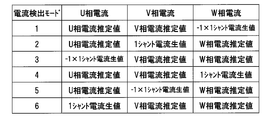
- the control unit 213 sets the current detection mode to these six patterns and identifies one phase to which the phase current detection value is to be assigned according to the current detection mode as described later. .
- the solid line in FIG. 6 is a sine wave waveform of an ideal phase current having no phase shift with respect to the motor angle, and the sine wave waveform of this ideal phase current is the peak value of the phase current and the motor according to the following formula It can be calculated based on the angle [deg (electrical angle)].
- U-phase current estimated value -sin (actual motor angle) * phase current peak value
- V-phase current estimated value -sin (actual motor angle-120 [deg]) * phase current peak value
- W-phase current estimated value -sin ( Actual motor angle-240 [deg]) * phase current peak value
- the actual phase current value can be calculated based on the following equation.
- U-phase current estimated value -sin (actual motor angle + ⁇ ) * phase current peak value
- V-phase current estimated value -sin (actual motor angle + ⁇ -120 [deg]) * phase current peak value
- W-phase current estimated value - sin (actual motor angle + ⁇ -240 [deg]) * phase current peak value
- the peak value of the phase current can be determined as the peak value of the phase current directly detected by the current detector 220, and the phase current directly detected by the current detector 220 has an electrical angle of 60 deg as described above. Since switching is performed every time, as shown in FIG. 7, the control unit 213 obtains peak values (maximum value, maximum value) for the phase currents of one phase detected in a plurality of sections of the electrical angle 60 deg. Used for estimation operation. In addition, the control unit 213 controls the current detection mode for switching the phase to which the phase current directly detected by the current detector 220 is to be assigned, every electrical angle 60 deg, the control duty of three phases (in other words, command voltage of each phase) Set based on Vu, Vv, Vw).
- Section 300-360 deg) is the first current detection mode, and the control duty of U-phase and W-phase is both less than 50%, and the control duty of V-phase is 50 deg. 60 deg section with 60 deg section where the control duty of V phase and W phase both exceeds 50% and the control duty of U phase is less than 50%.
- a section (electrical angle 180 to 240 deg. Section) with an electrical angle of 60 degrees where the control duty of U and W phases both exceed 50% and the control duty of V phase is less than 50% is the fifth current detection mode.
- the control unit 213 specifies one phase to which the phase current detection value is to be assigned for each current detection mode, and assigns the phase current estimation value to the remaining two phases. For example, in a section of the second current detection mode, a section in which the V-phase phase current is the largest among the three phases and the V-phase upper arm is on and the U-phase and W-phase upper arms are off (V-phase current The phase current of the V phase can be detected from the output of the current detector 220 in the detection period).
- the control unit 213 sets the detection timing of the V-phase current which is only once in one cycle of the PWM control in the V-phase current detection section, and performs A / D conversion at the detection timing.
- the phase current detection value read out is assigned as the phase current value of the V phase.
- the section in which the U-phase phase current is the smallest among the three phases, and the V-phase and W-phase upper arms are on and the U-phase upper arm is off U-phase current
- the phase current of the U phase can be detected from the output of the current detector 220 in the detection section).
- the control unit 213 sets the detection timing of the U-phase current that is only once in one cycle of the PWM control in the U-phase current detection interval, and performs A / D conversion at such detection timing.
- the phase current detection value read out is assigned as the phase current value of the U phase.
- the phase current detection value of the U phase is a current detector.
- the detected current value of 220 is multiplied by -1.
- the detected current value of the current detector 220 is assigned to the phase current value of the W phase
- -1 is added to the detected current value of the current detector 220.
- the multiplied value is assigned to the phase current value of the V phase
- the detected current value of the current detector 220 is assigned to the phase current value of the U phase in the section of the sixth current detection mode
- the current detector in the section of the first current detection mode A value obtained by multiplying the detected current value of 220 by -1 is assigned to the phase current value of the W phase.
- the control unit 213 obtains peak values (maximum values, maximum values) of the detected current value of the current detector 220 for each section of each current detection mode.
- the phase current of V phase is detected from the output of the current detector 220 every PWM1 cycle, so the phase current detection value of the V phase in the section of the second current detection mode
- the peak value is obtained from the time-series data of and the peak value used to calculate the phase current estimated value is updated with the peak value of the phase current detection value of this V phase.
- the phase current of the U phase is detected from the output of the current detector 220 every PWM1 cycle, so the phase current detection value of the U phase in the section of the third current detection mode
- the peak value is obtained from the time-series data of and the peak value used for the calculation of the phase current estimated value is updated with the peak value of the phase current detection value of this U phase.
- the peak value of the phase current detection value of the W phase is determined in the section of the fourth current detection mode, and the peak value of the phase current detection value of the V phase is determined in the section of the fifth current detection mode.
- the peak value of the phase current detection value of U phase is determined in the section of the mode, and the peak value of the phase current detection value of W phase is determined in the section of the first current detection mode. Update the peak value used.
- the peak value of the phase current as the phase current value of the remaining U phase and W phase
- an estimated value calculated according to the following equation based on the actual motor angle ⁇ ac [deg (electrical angle)] and the phase shift (current vector angle correction value) ⁇ at that time is assigned.
- U-phase current estimated value -sin (actual motor angle ⁇ ac + ⁇ ) * phase current peak value
- W-phase current estimated value -sin (actual motor angle ⁇ ac + ⁇ -240 [deg]) * phase current peak value
- one phase to which the detection current value of the current detector 220 is to be assigned is specified for each current detection mode (every 60 deg electrical angle), and the phase current peak value and the actual motor for the remaining two phases.
- the phase current estimated based on the angle ⁇ ac (reference current vector angle) and the phase shift is assigned.
- the hardware configuration for detecting the phase current can be simplified, and the A / D conversion load of the control unit 213 (microcomputer 213b) It can be reduced. And, by reducing the A / D conversion load, it becomes a phase current detection process applicable also to a drive device using a low function (low cost) microcomputer.
- phase current requires a period longer than the total time of the time required for A / D conversion and the current fluctuation period immediately after the start of energization, along with the decrease of the command voltage (command duty)
- the period may be shorter than the total time, and the phase current may not be detected.
- one cycle of PWM for setting the duty for which the phase current detection period is equal to or more than the total time and one cycle for setting the duty for which the period for detection of the phase current is less than the total time are alternated.
- a process to set hereinafter referred to as pulse shift process
- the phase current is detected when the phase current detection period is set to a duty that is equal to or greater than the total time, and the phase current is detected when the phase current detection period is set to a duty that falls below the total time. If the control of the average duty is equal to the command duty, the phase current can be detected while controlling the command duty (command torque).
- the above pulse shift processing causes noise, but if A / D conversion is performed once in one PWM control cycle as described above, two A / D conversions are performed in one PWM control cycle. As compared with the case where the phase current of two phases is separately detected, it is possible to make the duty region required to perform the pulse shift processing smaller, and to suppress the generation of noise due to the pulse shift processing.
- Equation 3 is an equation representing a voltage model of a three-phase brushless motor (IPMSM) 2 on the dq axes.
- Equation 3 Vd is d-axis voltage [V]
- Vq is q-axis voltage [V]
- Ra is d
- La is d
- ⁇ is motor rotational speed [ rad / sec] (electrical angle)
- Id is d-axis current [A]
- Iq is q-axis current [A]
- Ke is induced voltage constant [V / (rad / sec)] (electrical angle).
- the circuit equation of Eq. 3 can be divided into a resistance term, an interference term (speed electromotive force term), and an induced voltage term, as shown in Eq.
- the resistance term is a DC component
- the interference term is an interference voltage component between the d and q axes
- the induced voltage term is an induced voltage component generated on the q axis.
- the motor angle is the angle of the d axis
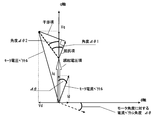
- the phase shift with respect to the motor angle (reference current vector angle) is ⁇ shown in FIG. 10.
- the phase shift is obtained by obtaining the current vector angle correction value ⁇ corresponding to this phase shift.
- Phase current can be estimated.
- the first angle ⁇ 1 is obtained from the d, q axis resistance Ra, the d, q axis inductance L, and the motor rotational speed ⁇ .
- the control unit 213 calculates the first angle ⁇ 1 based on the d, q axis resistance Ra, d, q axis inductance L, and the motor rotational speed ⁇ , and the q axis voltage Vq, d axis
- the second angle ⁇ 2 is calculated based on the voltage Vd, the motor rotational speed ⁇ , and the induced voltage constant Ke, and the current vector angle correction value ⁇ (phase shift) is calculated from these angles ⁇ 1 and ⁇ 2.
- the control unit 213 calculates the phase current estimated value based on the actually generated phase shift. And the phase current can be estimated with high accuracy.
- q-axis resistances Ra, d, q-axis inductances L used for calculation of the angles ⁇ 1 and ⁇ 2 and an induced voltage constant Ke are stored in advance as constants, and the angles ⁇ 1 and ⁇ 2 are calculated.
- a current vector angle correction value ⁇ is calculated.
- the d and q axis resistances Ra vary depending on the environmental conditions (temperature conditions and the like) of the three-phase brushless motor 2, and also vary for every three-phase brushless motor 2. Then, the d and q axis resistances Ra shift from the reference value (constant in the memory), the calculation accuracy of the current vector angle correction value ⁇ (phase shift) decreases, and by subtracting, the calculation accuracy of the phase current estimated value Decreases. Therefore, the control unit 213 detects the occurrence of the estimation error of the phase current estimation value due to the fluctuation of the d, q axis resistance Ra, and reduces the d, q axis resistance Ra (first angle ⁇ 1, current vector The angle correction value ⁇ ) is corrected.
- phase current value to be allocated to one phase is switched from the phase current detection value to the phase current estimated value when the absolute value of the phase current changes stepwise in the decreasing direction, in other words, the phase current estimation at switching time
- the control unit 213 sets the d, q axis resistance Ra to the phase current. Correct in the direction in which the phase of the estimated value advances.
- phase current value to be allocated to one phase is switched from the phase current detection value to the phase current estimated value when the absolute value of the phase current changes stepwise in the increasing direction, in other words, the phase current at switching If the estimated value is larger than the phase current detection value, the phase of the phase current estimated value leads the phase of the actual phase current, so the control unit 213 sets the d, q axis resistance Ra Correct in the direction in which the phase of the current estimate lags.
- the phase of the phase current estimated value advances, and conversely, the d and q axis resistances Ra used for computing the phase current estimated value are increased If this is done, the phase of the phase current estimate will be delayed.
- the control unit 213 switches the phase current value to be allocated to one phase from the phase current detection value to the phase current estimation value, the absolute value of the phase current changes stepwise in the decreasing direction, and the phase of the phase current estimation value
- correction is performed to reduce the d, q axis resistance Ra by a predetermined value ⁇ Ra than the current value.
- the control unit 213 switches the phase current value to be allocated to one phase from the phase current detection value to the phase current estimation value
- the absolute value of the phase current changes stepwise in the increasing direction, and the phase of the phase current estimation value
- correction is performed to increase the d, q axis resistance Ra by a predetermined value ⁇ Ra than the current value.
- the control unit 213 increases or decreases the d and q axis resistances Ra according to the step change amount (step) of the phase current when the phase current value to be allocated to one phase is switched from the phase current detection value to the phase current estimated value.
- the magnitude of the predetermined value ⁇ Ra to be corrected can be changed. That is, if the predetermined value ⁇ Ra is made larger as the absolute value of the step change amount of the phase current is larger, it is possible to bring the phase of the phase current estimated value close to the phase of the phase current detection value in a responsive manner.
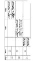
- FIG. 11 is a diagram showing the determination of the change amount of the phase current and the correction direction of the phase of the phase current estimated value based on the determination result for each switching pattern of the current detection mode.
- a value obtained by subtracting the absolute value of the W-phase estimated current value (current value) after switching from the absolute value of the phase current detection value (previous value) before switching falls below a predetermined value ⁇ Im ( ⁇ Im ⁇ 0) (
- ⁇ Im) that is, the absolute value of the W-phase current estimated value after switching is larger than the absolute value of the phase current detection value before switching by a predetermined amount and allocated to the W phase Since the phase of the W-phase current estimated value leads the phase of the actual W-phase current when the phase current to be stored increases stepwise, the control unit 213 sets the d, q axis resistance Ra to It corrects in the direction in which the phase of the phase current estimated value is delayed.
- the control unit 213 sets the d, q axis resistance Ra to the phase. Correct in the direction in which the phase of the current estimate advances.
- the d and q axis resistances Ra used for calculating the phase current estimated value are actual values. Since the control unit 213 does not correct the d and q axis resistances Ra, the control unit 213 maintains the d and q axis resistances Ra at the current values.
- the control unit 213 compares the phase current detection value before switching with the V phase current estimation value after switching.
- the control unit 213 switches from the absolute value of the phase current detection value (previous value) before switching as in the switching of the W-phase current value.
- the phase of the V-phase current estimated value leads the phase of the actual V-phase current by a predetermined amount or more It is determined whether there is a delay or more than a predetermined level, or whether the phase of the V-phase current estimated value and the phase of the actual V-phase current are sufficiently close.
- the control unit 213 reduces the phase difference to a smaller value d, q Correct the axis resistance Ra.
- the phase current assigned to the U phase is U from the phase current detection value. Since switching to the phase current estimation value is performed, the control unit 213 compares the phase current detection value before switching with the U phase current estimation value after switching.
- the control unit 213 switches from the absolute value of the phase current detection value (previous value) before switching to the switching value as in the switching of the W-phase current value.
- the phase of the U-phase current estimated value leads the phase of the actual U-phase current by a predetermined amount or more It is determined whether there is a delay or more than a predetermined amount, or whether the phase of the U-phase current estimated value and the phase of the actual U-phase current are sufficiently close to each other.
- the control unit 213 reduces the phase difference to a smaller value d, q Correct the axis resistance Ra.
- the control unit 213 corrects the current vector angle by causing the d and q axis resistances Ra used for calculation of the phase current estimated value (current vector angle correction value ⁇ , resistance term) to have an error with respect to the actual value.
- the control unit 213 corrects the d and q axis resistances Ra in the direction in which the phase current estimated value approaches the phase current detection value (the real phase current).
- the control unit 213 can calculate the phase current estimated value with high accuracy even if there is a change in environmental conditions (temperature change) or the characteristic variation of the three-phase brushless motor 2, and based on the three-phase current value. It can control 3-phase brushless motor with stable accuracy.
- the control unit 213 determines the d, q axis resistance Ra (current vector angle correction value ⁇ , resistance term from the step change of the allocated phase current value when the phase current detection value is switched to the phase current estimated value).
- the error of d, q axis resistance Ra can be determined from the step change of the assigned phase current value when the phase current estimated value is switched to the phase current detected value.
- the control unit 213 can correct the d, q axis resistance Ra (current vector angle correction value ⁇ , resistance term) based on the temperature condition. For example, when a temperature sensor for detecting the environmental temperature is provided, the control unit 213 corrects the d, q axis resistance Ra (current vector angle correction value ⁇ , resistance term) according to the environmental temperature obtained from the output of the temperature sensor be able to.
- control unit 213 performs energization for measuring the resistance value prior to activation of the three-phase brushless motor, estimates the temperature condition from the resistance value and the measured resistance value under the reference temperature condition, and estimates the temperature condition D, q-axis resistance Ra (current vector angle correction value ⁇ , resistance term) can be corrected based on
- control unit 213 calculates current vector angle correction value ⁇ based on q-axis voltage Vq, d-axis voltage Vd, motor rotational speed ⁇ , etc., but the phase of the phase current detection value with respect to the motor angle By detecting the current vector angle correction value .DELTA..theta. Can be set. Specifically, the control unit 213 detects phase current when the phase current assigned to one phase is switched from the phase current detection value to the phase current estimated value (in other words, at an electrical angle at which the current detection mode is switched) The current vector angle correction value ⁇ can be obtained from the value and the phase current peak value.
- the control unit 213 peaks the phase current detection value based on the phase current detection value immediately before switching when the phase current assigned to one phase is switched from the phase current detection value to the phase current estimation value, and the phase current peak value.
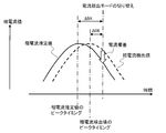
- control unit 213 is configured such that the phase current has a peak value in a sine wave waveform of an ideal phase current having no phase shift with respect to the motor angle or a phase current estimated value calculated based on the current vector angle correction value ⁇ .
- the angle from the timing at which the phase current detection value is switched to the phase current estimated value is set as ⁇ A (see FIG. 12).
- the control unit 213 calculates the current vector angle correction value ⁇ or the correction value ⁇ aj according to the following equation based on the angles ⁇ A and ⁇ B.
- ⁇ ( ⁇ aj) ⁇ A ⁇ B That is, when calculating the angle ⁇ A from the ideal current waveform, the above-mentioned calculation formula is from the timing when the actual current waveform peaks from the angle ⁇ A from the timing when the ideal current waveform peaks to the switching timing of the current detection mode By subtracting the angle ⁇ B until the switching timing of the current detection mode, the angle from the timing at which the ideal current waveform peaks to the timing at which the actual current waveform peaks is calculated, and the actual current relative to the ideal current waveform A phase shift of the waveform is detected.
- the above-mentioned arithmetic expression is a phase shift between the actual phase current waveform and the phase current estimated value, in other words The error of the current vector angle correction value .DELTA..theta. Therefore, by correcting the current vector angle correction value ⁇ based on the correction value ⁇ aj, the phase current estimated value can be made closer to the actual phase current waveform.
- the phase when the process of obtaining the current vector angle correction value ⁇ from the phase current detection value at the electrical angle at which the current detection mode is switched and the phase current peak value can be switched from the phase current detection value to the phase current estimated value
- the deviation between the current detection value and the phase current value of the ideal waveform is equal to or more than a predetermined value, in other words, it is performed when the phase deviation is equal to or more than a predetermined value, and prohibited when the deviation is less than a predetermined value can do.
- the detection sensitivity of the current vector angle correction value ⁇ is low in a state where the phase current deviation (phase shift) is small, and the calculation of the current vector angle correction value ⁇ is performed every electrical angle of 60 degrees which is a switching cycle of the current detection mode. Under conditions where the motor rotational speed is low, estimation delay occurs. Therefore, if the update calculation of the current vector angle correction value ⁇ is performed in a state where the phase current deviation (phase shift) is small, current control may diverge.
- motor constants related to the current vector angle correction value ⁇ include the resistance Ra, the inductance La, and the induced voltage constant Ke.
- the inductance La is not affected by the temperature, but the resistance Ra and The induced voltage constant Ke varies with temperature.
- the control unit 213 can estimate the values of the resistance Ra and the induced voltage constant Ke affected by the temperature as follows, and calculate the current vector angle correction value ⁇ using the estimated result.
- the angle between the interference term and the resistance term is a right angle
- the ⁇ * La * phase is centered on the tip of the motor voltage vector determined by the d axis voltage Vd and the q axis voltage Vq.
- a line corresponding to the term and a line connecting the intersection point C1 and the contact point C2 corresponds to the resistance term.
- the resistance term resistance Ra * phase current peak value Ipeak
- the control unit 213 stores the induced voltage constant Ke and the resistance Ra obtained as described above as constants, and the current vector angle correction value ⁇ based on the q-axis voltage Vq, the d-axis voltage Vd and the motor rotational speed ⁇ . Use these constants when calculating.
- the current vector angle correction value ⁇ can be calculated using the induced voltage constant Ke and the resistance Ra adapted to the environmental temperature at that time, and the estimation accuracy of the phase current estimated value is improved.
- the control unit 213 can calculate the induced voltage constant Ke according to the following equation based on the phase current peak value Ipeak obtained from the phase current detection value.
- Ke (Vq ⁇ (Ipeak) 2 * ( ⁇ 2 * La 2 + Ra 2 ) ⁇ Vd 2 )) / ⁇
- phase current estimated value is calculated using the current vector angle correction value ⁇ obtained based on the induced voltage constant Ke estimated as described above, a change in resistance Ra occurs, and the phase current detection value and the phase current
- the control unit 213 detects the phase current detection value at the time of switching the current detection mode and the phase current detection value as described above.
- the induced voltage constant Ke resistance
- the process of estimating Ra may be performed to set the current vector angle correction value ⁇ based on the induced voltage constant Ke, the resistance Ra, the q-axis voltage Vq, the d-axis voltage Vd, and the motor rotational speed ⁇ estimated. it can.
- the control unit 213 sets the length of the phase current detectable period to a predetermined length or more.
- the three-phase brushless motor 2 is replaced by the sensorless square wave drive system (120 degree conduction system) instead of the sensorless sine wave drive system. It can be driven.
- the above-mentioned rectangular wave drive method is a method of driving the brushless motor 2 by sequentially switching a selected pattern (energization mode) of two phases to which pulse voltage is applied among the three phases for each predetermined rotor position.
- the control unit 213 uses the voltage (transformer electromotive voltage, pulse induced voltage) induced in the non-energized phase (open phase) by applying a pulse-like voltage to the energized phase to obtain rotor position information
- the switching timing of the selection pattern of the energized phase is detected.
- phase current to be allocated to one phase is switched from the phase current detection value to the phase current estimation value or from the phase current estimation value to the phase current detection value with the switching of the current detection mode, the phase current before and after switching deviates If the phase current value before switching is set, the correction current value gradually approaching the phase current value after switching can be set, and the three-phase brushless motor 2 can be controlled transiently based on the correction current value concerned.
- phase to which the phase current detection value is allocated is fixed to two phases, and the phase current estimated value can be obtained for all three phases in the current detection mode where the phase current of the phase can not be detected directly from the output of current detector 220 Can be assigned.
- two phases to which phase current detection values are assigned are fixed to U phase and V phase, and phase current detection values are assigned to U phase in the third current detection mode and sixth current detection mode phase current to V phase and W phase Estimated values are assigned, and in the second current detection mode and fifth current detection mode, phase current detection values are assigned to the V phase, phase current estimated values are assigned to the U phase and the W phase, and first current detection mode and fourth current detection In the mode, phase current estimated values can be allocated to all three phases.
- a combination of two fixed phases to which a phase current detection value is allocated is switched at a predetermined cycle, or one phase to which a phase current detection value is allocated according to a mode for fixing two phases to which a phase current detection value is fixed
- the mode to be switched can be switched on the basis of conditions such as the motor rotational speed.
- SYMBOLS 1 Motor-type sub oil pump, 2 ... 3 phase brushless motor, 3 ... Motor drive unit (MCU) 212 ... Drive circuit (inverter circuit) 213 ... Control unit, 213a ... A / D converter, 213b ... Micro Computer, 220: current detector, 220a: shunt resistor, 220b: detection circuit
Landscapes
- Engineering & Computer Science (AREA)
- Power Engineering (AREA)
- Control Of Motors That Do Not Use Commutators (AREA)
- Control Of Ac Motors In General (AREA)
Abstract
Description
上記の検出方法を実施する場合に、PWMキャリア1周期(換言すれば、PWM制御周期)毎に3相の電流をそれぞれ検出するためには、PWMキャリア1周期毎に2回のA/D変換を行って電流検出器の出力をマイクロコンピュータが読み込む必要が生じる。
しかし、低機能(低価格)のマイクロコンピュータでは、PWMキャリア1周期に実施できるA/D変換の回数が1回に限られる場合があり、係るマイクロコンピュータで構成される駆動装置では、上記の相電流検出方法を適用できないという問題があった。
以下では、本発明に係るモータ駆動装置及び3相ブラシレスモータの相電流検出方法の一例として、車両用自動変速機の油圧機構を構成する3相ブラシレスモータの駆動に適用した例を説明する。
そして、サブオイルポンプ1は、例えば、内燃機関12がアイドルストップ制御などにより一時停止してメインオイルポンプ6が停止したときにメインオイルポンプ6に代わってオイルの供給を行ったり、メインオイルポンプ6の駆動中に補助的にオイル供給を行ったりするように駆動される。
モータ駆動装置3は、AT制御装置(ATCU)4からの指令に基づいて3相ブラシレスモータ2を駆動制御する。
変速機構7やアクチュエータ8に供給されたオイルはオイルパン10に戻されて再度サブオイルポンプ1及び/又はメインオイルポンプ6によって吸引され、オイルの閉回路を循環する。
サブオイルポンプ1の下流側のオイル配管5には、逆止弁11が配設されている。
例えば、ハイブリッド車両などにおいて内燃機関12の冷却水の循環に用いる電動式のウォータポンプを駆動する3相ブラシレスモータに、本願発明に係るモータ駆動装置及び3相ブラシレスモータの相電流検出方法を適用することができる。
3相ブラシレスモータ2を駆動するモータ駆動装置3は、駆動回路(インバータ回路)212と制御ユニット213とを備える。
制御ユニット213は、A/D変換器213aと、マイクロプロセッサ(CPU,MPUなど)やROM、RAMなどを含んで構成されるマイクロコンピュータ213bとを備え、AT制御装置4との間で通信を行う。
なお、3相ブラシレスモータ2は回転子の位置情報を検出するセンサを備えず、制御ユニット213は、ブラシレスモータ2の駆動制御を回転子の位置情報を検出するセンサを用いないセンサレス駆動方式によって行う。
インバータ212aのスイッチング素子217a~217fは例えばFETで構成され、スイッチング素子217a~217fの各制御端子(ゲート端子)は、制御ユニット213に接続される。
三角波比較方式のPWM制御においては、三角波(キャリア)と、指令デューティ比(指令電圧)に応じて設定されるPWMタイマとを比較することで、各スイッチング素子217a~217fをオン、オフさせるタイミングを検出する。
電流検出器220は、各相の下アームと電源回路219との間に直列に接続したシャント抵抗220aと、検出回路220bとから構成される。検出回路220bは、シャント抵抗220aの抵抗分で発生する電流に比例した電圧を検出し、係る電圧のアナログ信号を出力する。
制御ユニット213は、各相に正弦波電圧を加える正弦波駆動方式によってブラシレスモータ2を駆動する。
なお、3相ブラシレスモータ2が磁極位置センサを備え、制御ユニット213は、係る磁極位置センサの出力に基づきロータの角度(磁極位置)を検出して3相ブラシレスモータ2を駆動制御することができる。
図3において、3相電流検出部501は、検出回路220bの出力のA/D変換値(インバータ212aの直流母線電流)に基づき3相それぞれの相電流を検出する。
角度・角速度演算部502は、図4に示すように、軸誤差推定部651及び位置・速度推定部652を含む。
そして、軸誤差推定部651は、軸誤差Δθcを数1に従って算出する。

位置・速度推定部652では、軸誤差Δθcと基準値との差分に比例ゲインを乗算して得た値と、軸誤差Δθcと基準値との差分に積分ゲインを乗算した値の積分値とを合算し、当該合算値を積分してモータ角度(磁極位置)θを求める。
また、3相ブラシレスモータ2が磁極位置センサを備える場合、角度・角速度演算部502は、磁極位置センサの出力に基づいてモータ角度(磁極位置)及び角速度(モータ回転数)を検出する。
ベクトル制御部504には、指令トルクに応じた目標電流(d軸指令電流、q軸指令電流)と、角度・角速度演算部502で算出された角速度と、3相-2軸変換器503で求めた電流Id,Iqとが入力される。
2軸-3相変換器505では、指令電圧Vq,Vdを3相電圧Vu、Vv、Vwに変換して出力し、PWM変調部506では、変調波としての3相電圧Vu、Vv、Vwを三角波キャリアと比較することで、インバータ212aのスイッチング素子を駆動するためのスイッチングゲート波形を生成する。

図3に示したように、3相電流検出部501は、ピーク値抽出部601、3相電流推定値生成部602、及び、相電流割当部603を含んで構成される。
ピーク値抽出部601は、時系列に複数検出された電流検出値に基づき相電流のピーク値を抽出して、3相電流推定値生成部602に出力する。
U相電流推定値=-sin(電流ベクトル角度)*相電流ピーク値
V相電流推定値=-sin(電流ベクトル角度-120[deg])*相電流ピーク値
W相電流推定値=-sin(電流ベクトル角度-240[deg])*相電流ピーク値
相電流割当部603には、3相電流推定値生成部602が求めた3相の相電流推定値が入力され、更に、PWM制御の1周期に1回の検出タイミングにおいてA/D変換された、電流検出器220の検出回路220bの出力が入力される。
相電流割当部603によって特定された3相それぞれの相電流値は3相-2軸変換器503に出力され、3相-2軸変換器503は、入力した3つ相電流値を2軸の回転座標系(d-q座標系)の電流Id,Iqに変換し、ベクトル制御部504は、電流Id,Iqを用いてベクトル制御を実施する。
なお、本願では、中性点に流れ込む方向の相電流をプラスで表し、中性点から流れ出す方向の相電流をマイナスで表すものとする。
なお、V相の上アームがオンでU相及びW相の上アームがオフである区間は、三角波の谷を挟んで両側に発生し、PWM制御の1周期(キャリア1周期)内の2つの独立した区間で電流検出器220はV相の相電流を検出することが可能である。
電気角180degから240degの区間は、3相のうちのV相の相電流が最小となる区間であり、制御ユニット213は、PWM制御の1周期(キャリア1周期)においてU相及びW相の上アームがオンでV相の上アームがオフであって電源からU相及びW相に流れ込んだ電流が中性点で合流してV相に流れ込む2つの区間のうちの最初の区間(又は2番目の区間)内に相電流の検出タイミングを設定する。そして、制御ユニット213は、PWM制御の1周期に1回だけ電流検出器220の出力をA/D変換してV相の相電流値として読み込み、他のU相及びW相については、相電流検出値のピーク値に基づき演算した相電流推定値を割り当てる。
ここで、U相、V相、W相のうちの1相の相電流が最大となる3つの電気角60deg区間と、U相、V相、W相のうちの1相の相電流が最小となる3つの電気角60deg区間とに区別されるから、制御ユニット213は、電流検出モードをこれらの6パターンに設定し、後述するように電流検出モードに従って相電流検出値を割り当てる1相を特定する。
図6の実線は、モータ角度に対して位相ずれがない理想的な相電流の正弦波波形であり、この理想的な相電流の正弦波波形は、以下の数式によって相電流のピーク値及びモータ角度[deg(電気角)]に基づき算出することができる。
U相電流推定値=-sin(実モータ角度)*相電流ピーク値
V相電流推定値=-sin(実モータ角度-120[deg])*相電流ピーク値
W相電流推定値=-sin(実モータ角度-240[deg])*相電流ピーク値
U相電流推定値=-sin(実モータ角度+Δθ)*相電流ピーク値
V相電流推定値=-sin(実モータ角度+Δθ-120[deg])*相電流ピーク値
W相電流推定値=-sin(実モータ角度+Δθ-240[deg])*相電流ピーク値
また、制御ユニット213は、電流検出器220で直接検出される相電流を割り当てる相を電気角60deg毎に切り替えるための電流検出モードを、3相の制御デューティ(換言すれば、各相の指令電圧Vu、Vv、Vw)に基づき設定する。
また、V相及びU相の制御デューティが共に50%を下回り、かつ、W相の制御デューティが50%を上回る電気角60degの区間(電気角120~180deg区間)を第4電流検出モードとし、U相及びW相の制御デューティが共に50%を上回り、かつ、V相の制御デューティが50%を下回る電気角60degの区間(電気角180~240deg区間)を第5電流検出モードとし、V相及びW相の制御デューティが共に50%を下回り、かつ、U相の制御デューティが50%を上回る電気角60degの区間(電気角240~300deg区間)を第6電流検出モードとする。
例えば、第2電流検出モードの区間では、3相のうちでV相の相電流が最も大きく、V相の上アームがオンでU相及びW相の上アームがオフである区間(V相電流検出区間)で電流検出器220の出力からV相の相電流を検出できる。
また、第3電流検出モードの区間では、3相のうちでU相の相電流が最も小さく、V相及びW相の上アームがオンでU相の上アームがオフである区間(U相電流検出区間)で電流検出器220の出力からU相の相電流を検出できる。
なお、第3電流検出モードの区間では、中性点からU相に流れ込む電流を検出することになるので、係る電流の向きをマイナスで表す場合、U相の相電流検出値は、電流検出器220の検出電流値に-1を乗算した値となる。
更に、制御ユニット213は、図7に示したように、各電流検出モードの区間毎に、電流検出器220の検出電流値のピーク値(極大値、最大値)を求める。
また、第3電流検出モードの区間では、電流検出器220の出力からU相の相電流がPWM1周期毎に検出されるので、この第3電流検出モードの区間でのU相の相電流検出値の時系列データからピーク値を求め、相電流推定値の演算に用いるピーク値をこのU相の相電流検出値のピーク値で更新する。
U相電流推定値=-sin(実モータ角度θac+Δθ)*相電流ピーク値
W相電流推定値=-sin(実モータ角度θac+Δθ-240[deg])*相電流ピーク値
これにより、インバータ212aの直流母線電流を検出する電流検出器220を用い、しかも、電流検出器220の検出出力をPWM制御の1周期当たり1回だけA/D変換することで、3相の相電流をそれぞれ求めることができる。
このような場合、例えば、相電流検出期間が前記合計時間以上となるデューティを設定するPWM1周期と、相電流の検出期間が前記合計時間を下回る期間となるデューティを設定するPWM1周期とを交互に設定する処理(以下、パルスシフト処理という)を実施する。
上記のパルスシフト処理はノイズ要因になるが、上記のようにPWM制御の1周期に1回のA/D変換を行う構成であれば、PWM制御の1周期に2回のA/D変換を行って2相の相電流をそれぞれに検出する場合に比べて、パルスシフト処理の実施が要求されるデューティ領域を小さくでき、パルスシフト処理によるノイズの発生を抑制できる。
数3は、d-q軸上での3相ブラシレスモータ(IPMSM)2の電圧モデルを表す式である。


数4を基にベクトル図を表現すると図10のようになる。なお、ベクトル図では、d軸電流Id、q軸電流Iqの変化は無いと仮定し、かつ、Las項(インダクタンスの振幅)は無視するものとする。
ここで、図10中の第1角度Δθ1は、抵抗項と干渉項とがなす角度であり、以下の式に従って算出される。
Δθ1=tan-1(干渉項/抵抗項)=tan-1(ωL/Ra)
また、図10中の第2角度Δθ2は、モータ電圧ベクトルから誘起電圧項を引いたベクトルとq軸ベクトルとがなす角度であり、以下の式に従って算出される。
・Vd≧0のとき
Δθ2=tan-1((Vq-Keω)/Vd)-π/2
・Vd<0のとき
Δθ2=tan-1((Vq-Keω)/Vd)+π/2
そして、電流ベクトル角度補正値Δθは、Δθ=Δθ2-Δθ1として算出される。
制御ユニット213(電流ベクトル角度補正値演算部604)は、d,q軸抵抗Ra、d,q軸インダクタンスL、モータ回転数ωに基づき第1角度Δθ1を算出し、q軸電圧Vq、d軸電圧Vd、モータ回転数ω、誘起電圧定数Keに基づき第2角度Δθ2を算出し、これらの角度Δθ1、Δθ2から電流ベクトル角度補正値Δθ(位相ずれ)を算出する。
なお、制御ユニット213のメモリには、角度Δθ1、Δθ2の演算に用いるd,q軸抵抗Ra、d,q軸インダクタンスL、誘起電圧定数Keが定数として予め記憶されていて、角度Δθ1、Δθ2の演算においては、メモリから読み出したd,q軸抵抗Ra、d,q軸インダクタンスL、誘起電圧定数Keと、そのときのq軸電圧Vq、d軸電圧Vd、モータ回転数ωとに基づいて、電流ベクトル角度補正値Δθを算出する。
そこで、制御ユニット213は、d,q軸抵抗Raの変動による相電流推定値の推定誤差の発生を検出し、推定誤差が小さくなる方向にd,q軸抵抗Ra(第1角度Δθ1、電流ベクトル角度補正値Δθ)を補正する。
そして、制御ユニット213は、1相に割り当てられる相電流検出値から相電流推定値に切り替えたときに、相電流の絶対値が増える方向の偏差が発生したか減る方向の偏差が発生したかに基づき、d,q軸抵抗Raの変動によって位相ずれが進角方向に変化したか遅角方向に変化したか(換言すれば、d,q軸抵抗Raの増減変化方向)を判断することが可能である。
逆に、1相に割り当てる相電流値を相電流検出値から相電流推定値に切り替えたときに相電流の絶対値が増大方向にステップ的に変化した場合、換言すれば、切り替え時における相電流推定値が相電流検出値よりも大きい場合には、相電流推定値の位相が実際の相電流の位相よりも進んでいることになるので、制御ユニット213は、d,q軸抵抗Raを相電流推定値の位相が遅れる方向に修正する。
そこで、制御ユニット213は、1相に割り当てる相電流値を相電流検出値から相電流推定値に切り替えたときに相電流の絶対値が減少方向にステップ的に変化し、相電流推定値の位相を相電流検出値に近づけるために相電流推定値の位相を進める必要がある場合には、d,q軸抵抗Raを現状値よりも所定値ΔRaだけ減少させる補正を行う。
なお、制御ユニット213は、1相に割り当てる相電流値を相電流検出値から相電流推定値に切り替えたときの相電流のステップ変化量(段差)に応じて、d,q軸抵抗Raを増減補正する所定値ΔRaの大きさを変更することができる。つまり、相電流のステップ変化量の絶対値が大きいほど所定値ΔRaをより大きくすれば、相電流推定値の位相を相電流検出値の位相に応答良く近づけることが可能である。
第1電流検出モードから第2電流検出モードに切り替わったとき、及び、第4電流検出モードから第5電流検出モードに切り替わったときには、W相に割り当てられる相電流が相電流検出値からW相電流推定値に切り替えられるので、制御ユニット213は、切り替え前の相電流検出値と切り替え後のW相電流推定値とを比較する。
また、第2電流検出モードから第3電流検出モードに切り替わったとき、及び、第5電流検出モードから第6電流検出モードに切り替わったときには、V相に割り当てられる相電流が相電流検出値からV相電流推定値に切り替えられるので、制御ユニット213は、切り替え前の相電流検出値と切り替え後のV相電流推定値とを比較する。
また、第3電流検出モードから第4電流検出モードに切り替わったとき、及び、第6電流検出モードから第1電流検出モードに切り替わったときには、U相に割り当てられる相電流が相電流検出値からU相電流推定値に切り替えられるので、制御ユニット213は、切り替え前の相電流検出値と切り替え後のU相電流推定値とを比較する。
このように、制御ユニット213は、相電流推定値(電流ベクトル角度補正値Δθ、抵抗項)の演算に用いるd,q軸抵抗Raが実際値に対して誤差を有することで、電流ベクトル角度補正値Δθ引いては相電流推定値の演算精度が低下していることを、1相に割り当てられる相電流が相電流検出値から相電流推定値に切り替えられるときの電流変化に基づき検出する。そして、制御ユニット213は、相電流推定値が相電流検出値(実相電流)に近づく方向にd,q軸抵抗Raを補正する。
なお、制御ユニット213は、上記のように、相電流検出値から相電流推定値に切り替えられるときの割り当て相電流値のステップ変化からd,q軸抵抗Ra(電流ベクトル角度補正値Δθ、抵抗項)の誤差を判定するが、逆に、相電流推定値から相電流検出値に切り替えられるときの割り当て相電流値のステップ変化からd,q軸抵抗Raの誤差を判定することができる。
例えば、環境温度を検出する温度センサを備える場合、制御ユニット213は、温度センサの出力から求めた環境温度に応じてd,q軸抵抗Ra(電流ベクトル角度補正値Δθ、抵抗項)を補正することができる。また、制御ユニット213は、3相ブラシレスモータの起動に先立って抵抗値を計測するための通電を行い、基準温度条件で抵抗値と計測した抵抗値とから温度条件を推定し、推定した温度条件に基づいてd,q軸抵抗Ra(電流ベクトル角度補正値Δθ、抵抗項)を補正することができる。
詳細には、制御ユニット213は、1相に割り当てられる相電流が相電流検出値から相電流推定値に切り替えられるときの(換言すれば、電流検出モードが切り替えられる電気角での)相電流検出値と、相電流ピーク値とから、電流ベクトル角度補正値Δθを求めることができる。
Δθ(Δθaj)=ΔθA-ΔθB
つまり、理想電流波形から角度ΔθAを演算する場合、上記の演算式は、理想電流波形がピークとなるタイミングから電流検出モードの切り替えタイミングまでの角度ΔθAから、実際の電流波形のピークとなるタイミングから電流検出モードの切り替えタイミングまでの角度ΔθBを減算することで、理想電流波形がピークとなるタイミングから実際の電流波形がピークとなるタイミングまでの角度を算出することになり、理想電流波形に対する実電流波形の位相ずれが検出される。
なお、電流検出モードが切り替えられる電気角での相電流検出値と、相電流ピーク値とから電流ベクトル角度補正値Δθを求める処理を、相電流検出値から相電流推定値に切り替えられるときの相電流検出値と理想波形の相電流値との偏差が所定値以上であるとき、換言すれば、位相ずれが所定以上であるときに実施し、前記偏差が所定値を下回る場合に禁止する構成とすることができる。
そこで、制御ユニット213は、相電流検出値から相電流推定値に切り替えられるときの相電流検出値と理想波形の相電流値又は相電流推定値との偏差が所定値を下回る場合は、相電流推定値の演算に用いる電流ベクトル角度補正値Δθの更新を停止する。
係る温度に影響を受ける抵抗Ra及び誘起電圧定数Keの値を、制御ユニット213は以下のようにして推定し、推定した結果を用いて電流ベクトル角度補正値Δθを演算することができる。
つまり、交点C1で決まるq軸切片の長さLEは誘起電圧項を表し、誘起電圧項=Ke*ωであるからLE=Ke*ωとなり、長さLE及びそのときのモータ回転数ωから誘起電圧定数Keを下式に従って算出することができる。
Ke=LE/ω
距離D1=抵抗Ra*相電流ピーク値Ipeak
を満たすことになり、距離D1及び相電流ピーク値とから、抵抗Raを下式に従って算出することができる。
Ra=D1/Ipeak
Ke=(Vq-√(Ipeak)2*(ω2*La2+Ra2)-Vd2))/ω
例えば、電流ベクトル角度補正値Δθの演算に用いる抵抗Ra及び誘起電圧定数Keの推定処理において、推定した抵抗Ra及び誘起電圧定数Keの時系列データを平均化処理して電流ベクトル角度補正値Δθの演算に用いるようにしたり、推定した抵抗Ra及び誘起電圧定数Keが所定範囲を超えたときに推定結果を用いることを禁止したりすることができる。
例えば、相電流検出値を割り当てる2相をU相及びV相に固定し、第3電流検出モード及び第6電流検出モードのときにはU相に相電流検出値を割り当てV相及びW相に相電流推定値を割り当て、第2電流検出モード及び第5電流検出モードのときにはV相に相電流検出値を割り当てU相及びW相に相電流推定値を割り当て、第1電流検出モード及び第4電流検出モードのときには3相全てに相電流推定値を割り当てる構成とすることができる。
ここで、相電流検出値を割り当てる固定の2相の組み合わせを所定周期毎に切り替えたり、相電流検出値を割り当てる2相を固定するモードと電流検出モードに従って相電流検出値を割り当てる1相を順次切り替えるモードとをモータ回転数などの条件で切り替えたりすることができる。
Claims (8)
- 3相ブラシレスモータに交流電力を供給するインバータと、前記インバータの直流母線電流を検出する電流検出器と、前記電流検出器の出力を入力し前記インバータをPWM制御する制御部と、を含み、前記3相ブラシレスモータを正弦波駆動するモータ駆動装置であって、
前記制御部は、PWM制御の1周期に1回の検出タイミングにおいて相電流の絶対値が最大となる1相の相電流を前記電流検出器の出力から求め、前記検出タイミング毎に検出した相電流のピーク値、モータ角度、及び、モータ角度に対する実相電流波形の位相ずれに基づき残る2相の相電流を推定する、モータ駆動装置。 - 前記制御部は、相電流の絶対値が最大となる1相を各相の制御デューティに基づき設定する、請求項1記載のモータ駆動装置。
- 前記制御部は、前記位相ずれをd軸電圧、q軸電圧、及びモータ回転速度に応じて可変に設定する、請求項1記載のモータ駆動装置。
- 前記制御部は、前記3相ブラシレスモータのd-q軸上の電圧モデルにおいて抵抗項と干渉項とが生成する角度及びモータ電圧ベクトルから誘起電圧項を引いたベクトルとq軸ベクトルとが生成する角度に基づき前記位相ずれを求める、請求項1記載のモータ駆動装置。
- 前記制御部は、1相の相電流が前記電流検出器による検出値と推定値との間で切り替えられるときの電流偏差が小さくなるように前記位相ずれを補正する、請求項1記載のモータ駆動装置。
- 前記制御部は、1相の相電流が前記電流検出器による検出値と推定値との間で切り替えられるときの前記電流検出器による検出値、及び、前記ピーク値に基づいて前記位相ずれを求める、請求項1記載のモータ駆動装置。
- インバータのPWM制御によって正弦波駆動される3相ブラシレスモータの各相の相電流を、前記インバータの直流母線電流を検出する電流検出器の出力に基づき検出する方法であって、
相電流の絶対値が最大となる1相の相電流を検出する検出タイミングをPWM制御の1周期に1回設定するステップと、
前記検出タイミングにおいて前記電流検出器の出力から相電流検出値を求めるステップと、
前記相電流検出値のピーク値を求めるステップと、
モータ角度を検出するステップと、
前記モータ角度に対する実相電流波形の位相ずれを設定するステップと、
前記ピーク値、前記モータ角度、及び前記位相ずれに基づき相電流推定値を算出するステップと、
前記電流検出値を1相の相電流値として割り当て、前記電流推定値を残る2相に割り当てるステップと、
を含む、3相ブラシレスモータの相電流検出方法。 - 前記位相ずれを設定するステップは、前記3相ブラシレスモータのd-q軸上の電圧モデルにおいて抵抗項と干渉項とが生成する角度及びモータ電圧ベクトルから誘起電圧項を引いたベクトルとq軸ベクトルとが生成する角度に基づき前記位相ずれを求める、請求項7記載の3相ブラシレスモータの相電流検出方法。
Priority Applications (3)
| Application Number | Priority Date | Filing Date | Title |
|---|---|---|---|
| DE112016001622.0T DE112016001622B4 (de) | 2015-04-07 | 2016-03-31 | Motorantriebsvorrichtung und phasenstromerfassungsverfahren für dreiphasigen büstenlosen motor |
| CN201680017713.6A CN107509393B (zh) | 2015-04-07 | 2016-03-31 | 电机驱动装置及3相无刷电机的相电流检测方法 |
| US15/564,838 US10224843B2 (en) | 2015-04-07 | 2016-03-31 | Motor drive device and phase current detecting method for three-phase brushless motor |
Applications Claiming Priority (2)
| Application Number | Priority Date | Filing Date | Title |
|---|---|---|---|
| JP2015078782A JP6279507B2 (ja) | 2015-04-07 | 2015-04-07 | モータ駆動装置及び3相ブラシレスモータの相電流検出方法 |
| JP2015-078782 | 2015-04-07 |
Publications (1)
| Publication Number | Publication Date |
|---|---|
| WO2016163301A1 true WO2016163301A1 (ja) | 2016-10-13 |
Family
ID=57072594
Family Applications (1)
| Application Number | Title | Priority Date | Filing Date |
|---|---|---|---|
| PCT/JP2016/060699 Ceased WO2016163301A1 (ja) | 2015-04-07 | 2016-03-31 | モータ駆動装置及び3相ブラシレスモータの相電流検出方法 |
Country Status (5)
| Country | Link |
|---|---|
| US (1) | US10224843B2 (ja) |
| JP (1) | JP6279507B2 (ja) |
| CN (1) | CN107509393B (ja) |
| DE (1) | DE112016001622B4 (ja) |
| WO (1) | WO2016163301A1 (ja) |
Families Citing this family (27)
| Publication number | Priority date | Publication date | Assignee | Title |
|---|---|---|---|---|
| JP6539633B2 (ja) | 2016-10-13 | 2019-07-03 | 矢崎総業株式会社 | 圧着端子の製造方法 |
| CN106788062B (zh) * | 2017-02-24 | 2023-08-18 | 上海晶丰明源半导体股份有限公司 | 一种无刷直流电机的控制装置、系统和方法 |
| JP6373434B1 (ja) * | 2017-03-24 | 2018-08-15 | 三菱電機株式会社 | 交流回転電機の制御装置 |
| JP6805197B2 (ja) * | 2018-03-01 | 2020-12-23 | 株式会社東芝 | モータ制御用集積回路 |
| JP7067135B2 (ja) * | 2018-03-07 | 2022-05-16 | 株式会社デンソー | 電力変換装置 |
| US11695359B2 (en) * | 2018-04-24 | 2023-07-04 | Positec Power Tools (Suzhou) Co., Ltd | Autonomous apparatus |
| JP7009308B2 (ja) * | 2018-05-23 | 2022-01-25 | 株式会社ミツバ | モータ駆動装置 |
| US11697355B2 (en) * | 2018-08-22 | 2023-07-11 | Ford Global Technologies, Llc | Electrified vehicle electrical distribution system component protection systems and methods |
| CN109533014B (zh) * | 2018-12-19 | 2020-08-18 | 杭州湘滨电子科技有限公司 | 一种电动助力转向系统过流抑制方法及装置 |
| EP3734831B1 (en) * | 2019-04-30 | 2022-02-02 | Danfoss Editron Oy | Device and method for determining rotation of an induction machine |
| CN110086405A (zh) * | 2019-06-12 | 2019-08-02 | 浙江众邦机电科技有限公司 | 一种svpwm控制系统及其控制方法、装置及设备 |
| DE102019215853A1 (de) * | 2019-10-15 | 2021-04-15 | Brose Fahrzeugteile SE & Co. Kommanditgesellschaft, Würzburg | Verfahren zum Betreiben eines bürstenlosen und sensorlosen mehrphasigen Elektromotors |
| CN111024999B (zh) * | 2019-12-09 | 2022-03-29 | 上海汽车工业(集团)总公司 | 相电流计算方法和计算模块及其故障诊断方法和故障诊断系统 |
| CN115668744A (zh) * | 2020-06-16 | 2023-01-31 | 三菱电机株式会社 | 电动机驱动装置以及热泵装置 |
| TWI739608B (zh) * | 2020-09-25 | 2021-09-11 | 致新科技股份有限公司 | 馬達系統 |
| US11309812B1 (en) | 2020-09-28 | 2022-04-19 | Global Mixed-Mode Technology Inc. | Motor system |
| CN112468045B (zh) * | 2020-11-30 | 2022-03-29 | 东南大学 | 一种基于电流移相的永磁同步电机单电流传感器控制方法 |
| WO2023276320A1 (ja) * | 2021-06-29 | 2023-01-05 | 日本電産株式会社 | モータ制御装置および電動ポンプ装置 |
| CN113872484B (zh) * | 2021-09-27 | 2024-01-19 | 佛山市顺德区美的电子科技有限公司 | 三相电流重构方法、装置、设备和存储介质 |
| JP7881330B2 (ja) * | 2022-03-10 | 2026-06-29 | 株式会社コロナ | モータ制御装置 |
| KR102944412B1 (ko) * | 2022-06-20 | 2026-03-26 | 에이치엘만도 주식회사 | 3상 인버터의 상전류 센서 고장 진단 장치 및 방법 |
| JP7686305B2 (ja) | 2022-09-21 | 2025-06-02 | 浙大城市学院 | 二重巻線モータの制御とobc充電とを同時に実現する多重化トポロジー構造 |
| CN115441706B (zh) * | 2022-09-26 | 2024-05-31 | 上海铼钠克数控科技有限公司 | Pwm产生方法及电路、驱动器的控制方法、电机及系统 |
| JP7689941B2 (ja) * | 2022-10-28 | 2025-06-09 | アイダエンジニアリング株式会社 | 同期電動機の磁極位置補正量算出装置及び方法並びに同期電動機の制御装置 |
| CN116073719B (zh) * | 2023-03-06 | 2023-07-07 | 浙大城市学院 | 一种同时实现电流采样增益及延时补偿方法和系统 |
| WO2024225067A1 (ja) * | 2023-04-27 | 2024-10-31 | パナソニックIpマネジメント株式会社 | モータ制御装置 |
| WO2026093549A1 (fr) * | 2024-10-31 | 2026-05-07 | Valeo Systèmes d'Essuyage | Ensemble électrique comprenant une machine électrique tournante |
Citations (2)
| Publication number | Priority date | Publication date | Assignee | Title |
|---|---|---|---|---|
| JP2004159391A (ja) * | 2002-11-05 | 2004-06-03 | Nissan Motor Co Ltd | 3相交流電動機の制御装置 |
| JP2005192335A (ja) * | 2003-12-25 | 2005-07-14 | Toyota Industries Corp | インバータ装置およびモータ制御方法 |
Family Cites Families (16)
| Publication number | Priority date | Publication date | Assignee | Title |
|---|---|---|---|---|
| JP2563226B2 (ja) | 1992-10-16 | 1996-12-11 | 財団法人工業技術研究院 | 変換器用の電流検出方法 |
| JP3351631B2 (ja) * | 1994-08-24 | 2002-12-03 | 株式会社東芝 | 電気車制御装置 |
| US7432616B2 (en) * | 2003-03-17 | 2008-10-07 | Mitsubishi Denki Kabushiki Kaisha | Inverter device |
| JP4294602B2 (ja) * | 2005-02-18 | 2009-07-15 | パナソニック株式会社 | 多相モータのロータ磁極位置検出装置及びそれを備えたモータ駆動装置並びにモータ駆動方法 |
| JP4789660B2 (ja) * | 2006-03-15 | 2011-10-12 | パナソニック株式会社 | モータ駆動装置およびモータ駆動方法 |
| JP2007295655A (ja) * | 2006-04-21 | 2007-11-08 | Yaskawa Electric Corp | 電力変換装置 |
| JP2008005632A (ja) * | 2006-06-22 | 2008-01-10 | Matsushita Electric Ind Co Ltd | モータ駆動装置及びモータ駆動方法並びにディスク駆動装置 |
| JP4956123B2 (ja) * | 2006-09-28 | 2012-06-20 | 三洋電機株式会社 | モータ制御装置 |
| JP5377398B2 (ja) * | 2010-04-09 | 2013-12-25 | 日立アプライアンス株式会社 | モータ制御装置及びそのための相電流検出方法 |
| JP5510746B2 (ja) * | 2010-10-26 | 2014-06-04 | 株式会社デンソー | 電子装置 |
| JP5693177B2 (ja) * | 2010-11-26 | 2015-04-01 | 株式会社 和光電子 | 圧電振動子駆動回路 |
| JP5641335B2 (ja) * | 2011-01-31 | 2014-12-17 | 株式会社デンソー | 電力変換装置 |
| JP5751234B2 (ja) * | 2012-10-16 | 2015-07-22 | 株式会社デンソー | 交流電動機の制御装置 |
| CN103872952B (zh) * | 2012-12-18 | 2017-03-29 | 尼得科(北京)传动技术有限公司 | 一种开关磁阻电机控制装置及方法 |
| JP2014212584A (ja) * | 2013-04-17 | 2014-11-13 | 日立アプライアンス株式会社 | 電動機制御装置 |
| JP6129972B2 (ja) * | 2013-08-22 | 2017-05-17 | 日立オートモティブシステムズ株式会社 | 交流電動機の制御装置、交流電動機駆動システム、流体圧制御システム、位置決めシステム |
-
2015
- 2015-04-07 JP JP2015078782A patent/JP6279507B2/ja active Active
-
2016
- 2016-03-31 DE DE112016001622.0T patent/DE112016001622B4/de active Active
- 2016-03-31 WO PCT/JP2016/060699 patent/WO2016163301A1/ja not_active Ceased
- 2016-03-31 CN CN201680017713.6A patent/CN107509393B/zh active Active
- 2016-03-31 US US15/564,838 patent/US10224843B2/en active Active
Patent Citations (2)
| Publication number | Priority date | Publication date | Assignee | Title |
|---|---|---|---|---|
| JP2004159391A (ja) * | 2002-11-05 | 2004-06-03 | Nissan Motor Co Ltd | 3相交流電動機の制御装置 |
| JP2005192335A (ja) * | 2003-12-25 | 2005-07-14 | Toyota Industries Corp | インバータ装置およびモータ制御方法 |
Also Published As
| Publication number | Publication date |
|---|---|
| CN107509393A (zh) | 2017-12-22 |
| CN107509393B (zh) | 2019-08-09 |
| DE112016001622B4 (de) | 2025-04-17 |
| US10224843B2 (en) | 2019-03-05 |
| JP6279507B2 (ja) | 2018-02-14 |
| DE112016001622T5 (de) | 2018-01-04 |
| US20180115264A1 (en) | 2018-04-26 |
| JP2016201872A (ja) | 2016-12-01 |
Similar Documents
| Publication | Publication Date | Title |
|---|---|---|
| JP6279507B2 (ja) | モータ駆動装置及び3相ブラシレスモータの相電流検出方法 | |
| US10804831B2 (en) | Control apparatus for alternating-current rotary electric machine | |
| JP6015712B2 (ja) | 回転機の制御装置 | |
| US11362606B2 (en) | Control device for alternating-current electric motor | |
| KR101958159B1 (ko) | 모터 구동 장치 및 모터 구동 장치에서의 상전류 검출 방법 | |
| CN103493362B (zh) | 电动机控制装置 | |
| US9077278B2 (en) | AC motor control apparatus | |
| US20080061727A1 (en) | Motor control device | |
| US20040100222A1 (en) | Control device for electric motor | |
| JP7385538B2 (ja) | 電力変換装置、温度推定方法及びプログラム | |
| EP3070836B1 (en) | Methods of auto tuning machine parameters and systems thereof | |
| US20140225540A1 (en) | Control apparatus for ac motor | |
| JP2019129573A (ja) | 交流電動機の制御装置 | |
| JP6954150B2 (ja) | 交流電動機の制御装置 | |
| JP2010200430A (ja) | 電動機の駆動制御装置 | |
| JP6129972B2 (ja) | 交流電動機の制御装置、交流電動機駆動システム、流体圧制御システム、位置決めシステム | |
| JP2011004538A (ja) | インバータ装置 | |
| US12255558B2 (en) | Motor controller, motor system and method for controlling motor | |
| JP6954149B2 (ja) | 交流電動機の制御装置 | |
| JP7813675B2 (ja) | モータ制御装置並びに電動車両システム | |
| US11545924B2 (en) | Power conversion device, power conversion method and program | |
| JP4611216B2 (ja) | 交流モータ制御装置および制御方法 | |
| JP2010142047A (ja) | 電動機の磁極位置推定装置 | |
| JP7517939B2 (ja) | 誘導電動機の駆動制御装置および駆動制御方法 | |
| JP2024122139A (ja) | 制御装置 |
Legal Events
| Date | Code | Title | Description |
|---|---|---|---|
| 121 | Ep: the epo has been informed by wipo that ep was designated in this application |
Ref document number: 16776468 Country of ref document: EP Kind code of ref document: A1 |
|
| WWE | Wipo information: entry into national phase |
Ref document number: 15564838 Country of ref document: US |
|
| WWE | Wipo information: entry into national phase |
Ref document number: 112016001622 Country of ref document: DE |
|
| 122 | Ep: pct application non-entry in european phase |
Ref document number: 16776468 Country of ref document: EP Kind code of ref document: A1 |
|
| WWG | Wipo information: grant in national office |
Ref document number: 112016001622 Country of ref document: DE |