WO2016163167A1 - 化学蓄熱装置 - Google Patents
化学蓄熱装置 Download PDFInfo
- Publication number
- WO2016163167A1 WO2016163167A1 PCT/JP2016/055181 JP2016055181W WO2016163167A1 WO 2016163167 A1 WO2016163167 A1 WO 2016163167A1 JP 2016055181 W JP2016055181 W JP 2016055181W WO 2016163167 A1 WO2016163167 A1 WO 2016163167A1
- Authority
- WO
- WIPO (PCT)
- Prior art keywords
- adsorber
- reaction medium
- pressure
- amount
- reactor
- Prior art date
- Legal status (The legal status is an assumption and is not a legal conclusion. Google has not performed a legal analysis and makes no representation as to the accuracy of the status listed.)
- Ceased
Links
Images




Classifications
-
- F—MECHANICAL ENGINEERING; LIGHTING; HEATING; WEAPONS; BLASTING
- F28—HEAT EXCHANGE IN GENERAL
- F28D—HEAT-EXCHANGE APPARATUS, NOT PROVIDED FOR IN ANOTHER SUBCLASS, IN WHICH THE HEAT-EXCHANGE MEDIA DO NOT COME INTO DIRECT CONTACT
- F28D20/00—Heat storage plants or apparatus in general; Regenerative heat-exchange apparatus not covered by groups F28D17/00 or F28D19/00
-
- Y—GENERAL TAGGING OF NEW TECHNOLOGICAL DEVELOPMENTS; GENERAL TAGGING OF CROSS-SECTIONAL TECHNOLOGIES SPANNING OVER SEVERAL SECTIONS OF THE IPC; TECHNICAL SUBJECTS COVERED BY FORMER USPC CROSS-REFERENCE ART COLLECTIONS [XRACs] AND DIGESTS
- Y02—TECHNOLOGIES OR APPLICATIONS FOR MITIGATION OR ADAPTATION AGAINST CLIMATE CHANGE
- Y02E—REDUCTION OF GREENHOUSE GAS [GHG] EMISSIONS, RELATED TO ENERGY GENERATION, TRANSMISSION OR DISTRIBUTION
- Y02E60/00—Enabling technologies; Technologies with a potential or indirect contribution to GHG emissions mitigation
- Y02E60/14—Thermal energy storage
Definitions
- the present invention relates to a chemical heat storage device.
- a device described in Patent Document 1 As a conventional chemical heat storage device, for example, a device described in Patent Document 1 is known.
- the chemical heat storage device described in Patent Document 1 is disposed on the entire outer surface of the diesel oxidation catalyst, and includes a reactor having a reaction material that chemically reacts with ammonia (NH 3 ), and an adsorbent that physically adsorbs NH 3.
- An adsorber and a connection line for moving NH 3 between the reactor and the adsorber are provided.
- NH 3 is moved from the adsorber to the reactor to cause a chemical reaction between the NH 3 and the reactant, and heat is generated. It is transmitted to the diesel oxidation catalyst, and the diesel oxidation catalyst is heated.
- the exhaust heat of the exhaust gas is given to the reaction material of the reactor, whereby NH 3 and the reaction material are separated, and the separated NH 3 is separated from the reactor. It is collected in the adsorber.
- the adsorber is used in the subsequent heat generation control. Even if NH 3 is supplied from the reactor to the reactor, the amount of NH 3 is small, so that a sufficient amount of heat cannot be generated from the reaction material. In order to deal with such a problem, for example, it is conceivable that the completion of recovery in the recovery control of the adsorber is determined based on the NH 3 recovery rate of the adsorber. Further, the failure detection of the NH 3 supply system may be performed based on the NH 3 recovery rate of the adsorber.
- the reference value for calculating the NH 3 recovery rate of the adsorber that is, the state where the NH 3 recovery rate of the adsorber is 0% and 100% It is necessary to accurately recognize the NH 3 adsorption amount of the adsorber in each of the states.
- An object of the present invention is to provide a chemical heat storage device capable of accurately recognizing the amount of adsorbing reaction medium adsorbed in each of the adsorber reaction medium recovery rate of 0% and 100%. .
- a chemical heat storage device generates heat and is heated by a chemical reaction between an adsorber having an adsorbent capable of adsorbing and desorbing a reaction medium and the reaction medium.
- a reactor having a reaction material that absorbs heat and desorbs the reaction medium, a supply pipe that connects the adsorber and the reactor so that the reaction medium can flow between the adsorber and the reactor, and an adsorption
- the reaction medium is supplied from the adsorber to the reactor, the pressure change amount per unit time in the adsorber is obtained based on the pressure in the adsorber.
- the adsorber reaction medium adsorption amount estimated by using the pressure in the adsorber when the amount of pressure change per unit time in the adsorber becomes equal to or less than the first predetermined value is the reaction medium recovery rate of the adsorber.
- the adsorber reaction medium adsorption amount estimated using the pressure in the adsorber when the pressure change amount per unit time in the adsorber becomes equal to or less than the first predetermined value is used as the reaction medium recovery of the adsorber. It is set to the reaction medium adsorption amount of the adsorber in a state where the rate is 0%. Thereby, the reaction medium adsorption amount of the adsorber when the reaction medium recovery rate of the adsorber is 0% can be accurately recognized.
- the adsorber reaction medium adsorption amount estimated using the pressure in the adsorber when the pressure change amount per unit time in the adsorber becomes the second predetermined value or less is used as the reaction medium recovery of the adsorber. It is set to the reaction medium adsorption amount of the adsorber when the rate is 100%. Thereby, the reaction medium adsorption amount of the adsorber when the reaction medium recovery rate of the adsorber is 100% can be accurately recognized.
- the first setting unit estimates a reaction medium adsorption amount of the adsorber as a first update value using a pressure in the adsorber when a pressure change amount per unit time in the adsorber becomes equal to or less than a first predetermined value.
- the reaction medium adsorption amount of the adsorber when the adsorber reaction medium recovery rate is 0% is corrected from the first initial value set when the adsorber is filled with the reaction medium to the first updated value, 2
- the setting unit estimates the reaction medium adsorption amount of the adsorber as a second update value using the pressure in the adsorber when the pressure change amount per unit time in the adsorber becomes equal to or less than the second predetermined value.
- the reaction medium adsorption amount of the adsorber when the reaction medium recovery rate of the adsorber is 100% may be corrected from the second initial value set when the adsorber is filled with the reaction medium to the second updated value. .
- the reaction medium recovery rate of the adsorber is 0%.
- the reaction medium adsorption amount of the adsorber in each of the state and the 100% state can be accurately recognized.
- the adsorber temperature acquisition unit further acquires an adsorber temperature
- the first setting unit and the second setting unit are configured to adsorb the reaction medium adsorbed on the adsorber based on the pressure in the adsorber and the temperature of the adsorber. May be estimated. In this case, the reaction medium adsorption amount of the adsorber can be easily estimated.
- a chemical heat storage device capable of accurately recognizing the amount of adsorption of the reaction medium of the adsorber when the reaction medium recovery rate of the adsorber is 0% and 100%.
- FIG. 4 is a conceptual diagram showing a flow of NH 3 between the adsorber and the reactor shown in FIG. 3.
- NH 3 is a graph showing an example of the saturated vapor pressure characteristics and NH 3 adsorption properties.
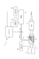
- FIG. 1 is a schematic configuration diagram illustrating an exhaust purification system including an embodiment of a chemical heat storage device.
- an exhaust purification system 1 is provided in an exhaust system of a diesel engine 2 (hereinafter simply referred to as “engine 2”) of a vehicle, and purifies harmful substances (environmental pollutants) contained in exhaust gas discharged from the engine 2. To do.
- the exhaust purification system 1 includes a heat exchanger 3, a diesel oxidation catalyst (DOC) 4, a diesel exhaust particulate removal filter (DPF) 5, a selective reduction catalyst (SCR) 6 and an ammonia slip.
- a catalyst (ASC: Ammonia Slip Catalyst) 7 is provided.
- the heat exchanger 3, the DOC 4, the DPF 5, the SCR 6, and the ASC 7 are sequentially disposed in the exhaust passage 8 connected to the engine 2 from the upstream side toward the downstream side.
- the heat exchanger 3 includes a cylindrical outer tube 9 and a honeycomb-structured heat exchange unit 10 disposed in the outer tube 9.
- the outer cylinder 9 has a function as an exhaust pipe that forms a part of the exhaust passage 8.
- the outer cylinder 9 is made of, for example, stainless steel.
- the heat exchange unit 10 exchanges heat between the exhaust gas and the reaction material 17 (described later) while the exhaust gas flows.
- the heat exchanging section 10 is made of ceramic such as SiSiC (non-oxide ceramic silicon carbide) having high thermal conductivity, or metal such as stainless steel having high thermal conductivity.
- the DOC 4 oxidizes and purifies HC, CO, and the like contained in the exhaust gas.
- the DPF 5 removes PM from the exhaust gas by collecting particulate matter (PM) contained in the exhaust gas.
- the SCR 6 reduces and purifies NO x contained in the exhaust gas with urea or ammonia (NH 3 ).
- ASC7 oxidizes NH 3 passing through the SCR6.
- the exhaust purification system 1 also includes a chemical heat storage device 11 that heats (warms up) the exhaust gas to be heated using a reversible chemical reaction without requiring external energy such as electric power. Yes.
- the chemical heat storage device 11 stores the heat (exhaust heat) of the exhaust gas by separating the reaction material 17 (described later) and the reaction medium, and reacts with the reaction medium when necessary.
- the exhaust gas is heated by causing a chemical reaction with the material 17 to generate reaction heat.
- ammonia NH 3
- NH 3 ammonia
- the chemical heat storage device 11 includes a reactor 12, an adsorber 13, and a reactor so that NH 3 can flow between the reactor 12 and the adsorber 13. 12 and an NH 3 supply pipe 14 for connecting the adsorber 13.
- the NH 3 supply pipe 14 is provided with a valve 15 for opening and closing the NH 3 flow path between the reactor 12 and the adsorber 13.
- the reactor 12 is disposed around the heat exchanger 3.
- the reactor 12 includes the outer cylinder 9, the outer cylinder 16, and the reaction material 17 disposed between the outer cylinder 9 and the outer cylinder 16.
- the reaction material 17 is a material that generates heat due to a chemical reaction with NH 3 when NH 3 is supplied, and absorbs the heat when it is heated from the outside to desorb chemically adsorbed NH 3. .
- the outer cylinder 9 of the heat exchanger 3 also serves as a part of the reactor 12.
- the outer cylinder 16 is made of a metal such as stainless steel.
- the outer cylinder 9 and the outer cylinder 16 constitute a container 18 for accommodating the reaction material 17 together with two connecting plates (not shown) before and after connecting the two.
- MXa a halide represented by the composition formula MXa is used.
- M is an alkaline earth metal such as Mg, Ca or Sr, or a transition metal such as Cr, Mn, Fe, Co, Ni, Cu or Zn.
- X is Cl, Br, I or the like.
- a is a number specified by the valence of M, and is 2 to 3.
- the reaction material 17 may be in the form of powder or a press-molded body. Further, the reaction material 17 may be mixed with an additive for improving thermal conductivity. As the additive, carbon fiber, carbon bead, SiC bead, metal bead, polymer bead, polymer fiber or the like is used. Examples of the metal material of the metal beads include Cu, Ag, Ni, Ci—Cr, Al, Fe, and stainless steel.
- a heat insulating material 19 is disposed between the outer cylinder 16 and the reaction material 17.
- the heat insulating material 19 for example, glass wool is used.
- One end portion of the NH 3 supply pipe 14 passes through the outer cylinder 16 and the heat insulating material 19 and opens to the accommodation region of the reaction material 17.
- a porous body (not shown) that forms a NH 3 flow path may be interposed between the reaction material 17 and the heat insulating material 19.
- the adsorber 13 has an adsorbent 20 capable of physical adsorption and desorption of NH 3 .
- adsorbent 20 capable of physical adsorption and desorption of NH 3 .
- activated carbon, carbon black, mesoporous carbon, nanocarbon, zeolite, or the like is used.
- the valve 15 is opened, so that the adsorber 13 NH 3 desorbed from the adsorbent 20 is supplied to the reactor 12 through the NH 3 supply pipe 14.
- the reaction material 17 for example, MgCl 2
- the heat generated from the reaction material 17 is transmitted to the heat exchanger 3, and the exhaust gas flowing through the heat exchanger 3 is heated (warmed up) by the heat. Then, the heated exhaust gas raises the DOC 4 to an activation temperature suitable for the purification of pollutants.
- the chemical heat storage device 11 includes a temperature sensor 21, a temperature sensor 22 (adsorber temperature acquisition unit), a pressure sensor 23 (adsorber pressure acquisition unit), and a controller 24. ing.
- the temperature sensor 21 is connected to the upstream side of the heat exchanger 3 in the exhaust passage 8 and detects and acquires the temperature of the exhaust gas flowing through the upstream side of the heat exchanger 3 in the exhaust passage 8.
- the temperature sensor 22 is connected to the adsorber 13 and detects and acquires the temperature of the adsorber 13.
- the pressure sensor 23 is connected to the adsorber 13 and detects and acquires the pressure in the adsorber 13.
- the controller 24 inputs the detection values of the temperature sensors 21 and 22 and the pressure sensor 23, performs a predetermined process, controls the valve 15, and the NH 3 recovery rate of the adsorber 13 is 0% and 100%.
- the NH 3 adsorption amount of the adsorber 13 in each of the states is set.
- the adsorber 13 in the initial state of the adsorber 13, when the valve 15 is opened, the adsorber 13 has a predetermined pressure in the reaction system including the reactor 12, the adsorber 13, and the NH 3 supply pipe 14.
- the holding NH 3 for holding pressure and the moving NH 3 used for the chemical reaction with the reaction material 17 to obtain a desired exothermic temperature are adsorbed and held. Therefore, the NH 3 recovery rate of the adsorber 13 is present in the adsorber 13 with respect to the total amount of NH 3 for movement to be moved from the adsorber 13 to the reactor 12 in order to obtain a desired temperature during the exothermic reaction (recovered).
- E) The ratio of NH 3 is shown.
- the state in which the NH 3 recovery rate of the adsorber 13 is 0% means that only the pressure holding NH 3 is adsorbed and held in the adsorbent 20 in the adsorber 13, and the moving NH 3 in the adsorber 13 is absorbed. Indicates that the amount of is zero.
- the state in which the NH 3 recovery rate of the adsorber 13 is 100% means that all of the moving NH 3 used for heat generation in the reactor 12 is recovered in the adsorber 13 and the pressure is maintained in the adsorber 13. It shows that there is NH 3 for use and NH 3 for transfer. Note that the adsorbed NH 3 amount of adsorber 13 is that the amount of NH 3 adsorbed in the adsorbent 20 of the adsorber 13.
- Controller 24 the first initial value A of the adsorbed NH 3 amount of adsorber 13 in a state NH 3 recovery of 0% adsorbers 13 (see FIG. 7 (a)), NH 3 recovered adsorbers 13
- the second initial value B (see FIG. 7B) of the NH 3 adsorption amount of the adsorber 13 in a state where the rate is 100% is stored.
- the initial values A and B of the NH 3 adsorption amount are based on various conditions such as the volume of the reactor 12 and the adsorber 13, the amount of heat to be generated in the reactor 12, the NH 3 filling pressure, the filling time, and the like. Is set.
- the NH 3 adsorption amount of the adsorber 13 when the NH 3 recovery rate of the adsorber 13 is 0% is required to keep the pressure in the adsorber 13 at a predetermined pressure.
- NH 3 sealed in the adsorber 13 is different from a liquid reaction medium such as water.
- the amount may vary from product to product.
- the actual NH 3 adsorption amount of the adsorber 13 in each of the state where the NH 3 recovery rate of the adsorber 13 is 0% and the state of 100% is the state where the NH 3 recovery rate of the adsorber 13 is 0%.
- the NH 3 adsorption amount of the adsorber 13 in each of the 100% states deviates from the initial value. Therefore, the controller 24 corrects the NH 3 adsorption amount of the adsorber 13 when the NH 3 recovery rate of the adsorber 13 is 0% and 100%, respectively.
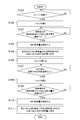
- FIG. 4 is a flowchart showing details of a processing procedure executed by the controller 24. This process is executed when the catalyst is warmed up when the exhaust gas temperature is low, such as when the engine 2 is started. Note that the valve 15 is closed at the start of execution of this process. Further, the NH 3 recovery rate of the adsorber 13 is 100%.
- the controller 24 first determines whether or not the engine 2 has been started (step S101). Whether or not the engine 2 has been started is determined, for example, based on whether or not an ignition switch is turned on.
- step S102 if the controller 24 determines that the exhaust gas temperature is low when the engine 2 is started, the controller 24 controls to open the valve 15 in order to warm the exhaust gas (step S102).
- the valve 15 When the valve 15 is opened, NH 3 is supplied from the adsorber 13 to the reactor 12 due to the pressure difference between the adsorber 13 and the reactor 12, as shown in FIG.
- the reaction material 17 in the reactor 12 and NH 3 react chemically to generate heat.
- NH 3 moves from the adsorber 13 to the reactor 12 with the passage of time, and the amount of NH 3 adsorption in the adsorber 13 gradually decreases, so the pressure in the adsorber 13 gradually decreases.
- a predetermined time elapses, the pressure fluctuation per unit time in the adsorber 13 decreases, and the pressure in the adsorber 13 becomes a substantially constant value.
- the controller 24 obtains the pressure change amount per unit time in the adsorber 13 based on the detection value of the pressure sensor 23, and the threshold value P in which the pressure change amount per unit time in the adsorber 13 is determined in advance. It is determined whether or not (first predetermined value) or less (step S103).
- the controller 24 determines that the pressure change amount per unit time in the adsorber 13 is equal to or less than the threshold value P, the NH 3 adsorption amount of the adsorber 13 based on the detection values of the temperature sensor 22 and the pressure sensor 23. Is estimated as the first update value (step S104).
- the estimated value of the NH 3 adsorption amount is estimated using the NH 3 saturated vapor pressure characteristic shown in FIG. 6A and the NH 3 adsorption characteristic shown in FIG.
- the NH 3 saturated vapor pressure characteristic shown in FIG. 6A is a graph showing the relationship between the temperature of the adsorber 13 and the NH 3 saturated vapor pressure, and the NH 3 saturated vapor pressure increases as the temperature of the adsorber 13 increases. It has the characteristic that becomes high.
- the NH 3 adsorption characteristic shown in FIG. 6B is a graph showing the relationship between the relative pressure and the NH 3 adsorption amount of the adsorber 13, and the NH 3 adsorption amount of the adsorber 13 increases as the relative pressure increases. It has the characteristic which becomes.
- the relative pressure is a ratio (P / P sat ) between the NH 3 saturated vapor pressure P sat and the pressure P in the adsorber 13.
- the controller 24 first obtains the NH 3 saturated vapor pressure P sat corresponding to the temperature T of the adsorber 13 detected by the temperature sensor 22 from the NH 3 saturated vapor pressure characteristic. Then, the controller 24 calculates a relative pressure that is a ratio between the NH 3 saturated vapor pressure P sat and the pressure P of the adsorber 13 detected by the pressure sensor 23. Then, the controller 24 obtains the NH 3 adsorption amount S nh3 corresponding to the relative pressure from the NH 3 adsorption characteristics. Thereby, the NH 3 adsorption amount can be easily estimated.
- the controller 24 uses the NH 3 adsorption amount of the adsorber 13 estimated when the pressure change amount per unit time in the adsorber 13 is equal to or less than the threshold value P, and the NH 3 recovery rate of the adsorber 13 is 0. % Is set to the NH 3 adsorption amount of the adsorber 13 (step S105).
- the updated value is A + ⁇
- the NH 3 adsorption amount of the adsorber 13 in a state where the NH 3 recovery rate of the adsorber 13 is 0% is set when the adsorber 13 is charged with NH 3 .
- the initial value A is corrected to the first update value A + ⁇ . Therefore, when the NH 3 recovery rate of the adsorber 13 is 0%, the NH 3 adsorption amount of the adsorber 13 is A + ⁇ .
- the controller 24 controls to close the valve 15 (step S106). Thereafter, the controller 24 estimates the temperature of the reactor 12 based on the detected value of the temperature sensor 21, and determines whether or not the temperature of the reactor 12 is equal to or higher than the reproducible temperature (step S107).
- the controller 24 determines that the temperature of the reactor 12 is equal to or higher than the regenerative temperature
- the controller 24 controls to open the valve 15 in order to recover NH 3 (step S108).
- the valve 15 is opened, NH 3 is supplied from the reactor 12 to the adsorber 13 as shown in FIG. 5B, and NH 3 is recovered in the adsorber 13 as described above.
- NH 3 moves from the reactor 12 to the adsorber 13 and the amount of NH 3 adsorbed in the adsorber 13 gradually increases, so that the pressure in the adsorber 13 gradually increases.
- a predetermined time elapses, the pressure fluctuation per unit time in the adsorber 13 decreases, and the pressure in the adsorber 13 becomes a substantially constant value.
- the controller 24 obtains the pressure change amount per unit time in the adsorber 13 based on the detection value of the pressure sensor 23, and the threshold value Q in which the pressure change amount per unit time in the adsorber 13 is determined in advance. It is determined whether or not (second predetermined value) or less (step S109).
- the threshold value Q used here may be the same value as or different from the threshold value P used in step S103.
- the controller 24 determines that the pressure change amount per unit time in the adsorber 13 has become the threshold value Q or less, the NH 3 adsorption of the adsorber 13 based on the detected values of the temperature sensor 22 and the pressure sensor 23.
- the amount is estimated as the second update value (step S110).
- the estimation of the NH 3 adsorption amount is performed by the same method as in the above step S104.
- the controller 24 determines the NH 3 adsorption amount of the adsorber 13 estimated when the pressure change amount per unit time in the adsorber 13 is equal to or less than the threshold value Q, and the NH 3 recovery rate of the adsorber 13 is 100%.
- the NH 3 adsorption amount of the adsorber 13 in this state is set (step S111).
- the renewal value is B + ⁇
- the NH 3 adsorption amount of the adsorber 13 in a state where the NH 3 recovery rate of the adsorber 13 is 100% is set to the second value described above when the adsorber 13 is charged with NH 3 .
- the initial value B is corrected to the second updated value B + ⁇ . Therefore, when the NH 3 recovery rate of the adsorber 13 is 100%, the NH 3 adsorption amount of the adsorber 13 is B + ⁇ .
- the controller 24 obtains the pressure change amount per unit time in the adsorber 13 based on the pressure in the adsorber 13, and the adsorber 13.
- the NH 3 adsorption amount of the adsorber 13 estimated using the pressure in the adsorber 13 when the amount of pressure change per unit time becomes equal to or less than the first predetermined value is used as the NH 3 recovery rate of the adsorber 13.
- first setting unit that sets the adsorbed NH 3 amount of adsorber 13 at 0% state, when the NH 3 is supplied to the adsorber 13 from the reactor 12, the adsorber on the basis of the pressure within the adsorber 13 The amount of pressure change per unit time in 13 is obtained, and the adsorber estimated using the pressure in the adsorber 13 when the amount of pressure change per unit time in the adsorber 13 becomes equal to or less than the second predetermined value.
- the NH 3 adsorption of 13, NH 3 recovery adsorbers 13 Has a second setting unit that sets the NH 3 adsorption amount of the adsorber 13 in a state of 100%.
- the NH 3 recovery operation is terminated when the NH 3 recovery rate of the adsorber 13 reaches a predetermined value or more (for example, 80% or more), and is controlled to prepare for the next heat generation operation. Then, the NH 3 adsorption amount of the adsorber 13 when the NH 3 recovery rate of the adsorber 13 is 100% is as shown in FIG. 7B when the NH 3 recovery rate is actually 100%.
- the amount is set lower than the adsorption amount (second initial value B)
- the a sufficient amount of NH 3 is actually recovered in the adsorber 13. Will not be.
- FIG. 7 (a) shows the adsorbed NH 3 amount of adsorber 13 in a state NH 3 recovery of 0% adsorbers 13, as shown in FIG. 7 (a), when the actual NH 3 recovery ratio was 0%
- FIG. 7B shows the NH 3 adsorption amount of the adsorber 13 when the NH 3 recovery rate of the adsorber 13 is 100% when set to an amount lower than the adsorption amount (first initial value A).
- the NH 3 adsorption amount of adsorber 13 which is estimated using the sets to adsorbed NH 3 amount of adsorber 13 in a state NH 3 recovery of 0% adsorber 13.
- the pressure change amount per unit time in the adsorber 13 was estimated using the pressure in the adsorber 13 when the pressure change amount per unit time was equal to or less than the threshold value Q.
- the NH 3 adsorption amount of adsorber 13 is set to adsorbed NH 3 amount of adsorber 13 in a state NH 3 recovery is 100% of the adsorber 13.
- the NH 3 adsorption amount of the adsorber 13 when the NH 3 recovery rate of the adsorber 13 is 0% is changed to the adsorber 13.
- the first initial value A set at the time of NH 3 filling is corrected to the NH 3 adsorption amount (first updated value A + ⁇ ) of the adsorber 13 estimated using the pressure in the adsorber 13, and the inside of the adsorber 13 is corrected.
- the NH 3 adsorption amount of the adsorber 13 when the NH 3 recovery rate of the adsorber 13 is 100% is set when the adsorber 13 is charged with NH 3.
- the second initial value B is corrected to the NH 3 adsorption amount (second updated value B + ⁇ ) of the adsorber 13 estimated using the pressure in the adsorber 13.
- the update value may be smaller than the initial value.
- the first initial value A is corrected as the first update value A- ⁇
- the second initial value B is corrected as the second update value B- ⁇ .
- the temperature of the adsorber 13 is directly detected by the temperature sensor 22 connected to the adsorber 13, but the present invention is not limited to this, and the detection value of the temperature sensor connected to the reactor 12 is used. It may be used to estimate the temperature of the adsorber 13.
- the pressure in the adsorber 13 is directly detected by the pressure sensor 23 connected to the adsorber 13, but the present invention is not limited to this, and the adsorber is detected using the detection value of the pressure sensor connected to the reactor 12. The pressure in 13 may be estimated.
- the temperature of the exhaust gas which flows through the part upstream from the heat exchanger 3 in the exhaust passage 8 is detected by the temperature sensor 21, and the temperature of the reactor 12 is estimated using the detected value.
- the temperature sensor used for estimating the temperature of the reactor 12 is not particularly limited thereto.
- the temperature of the exhaust gas flowing through the portion of the exhaust passage 8 downstream of the heat exchanger 3 may be detected by a temperature sensor, and the temperature of the reactor 12 may be estimated using the detected value. If the temperature sensor can be attached to the reactor 12, the temperature of the reactor 12 itself may be directly detected by the temperature sensor.
- the gaseous reaction medium is not particularly limited to NH 3 , for example, CO 2 or the like may be used.
- the reaction material that chemically reacts with CO 2 includes MgO, CaO, BaO, Ca (OH) 2 , Mg (OH) 2 , Fe (OH) 2 , Fe (OH) 3 , FeO, and Fe 2 O 3. or it can be used Fe 3 O 4 or the like.
- the reactor 12 is arrange
- this invention is an inside of an exhaust pipe, and the reactor and heat exchanger which have a reaction material alternately
- the present invention can also be applied to a chemical heat storage device that is laminated.
- the exhaust gas discharged from the diesel engine 2 is heated (warmed up).
- the present invention is not limited to this, and the chemical heat storage for heating the exhaust gas discharged from the gasoline engine is used.
- the present invention may be applied to an apparatus or the like, and the present invention may be applied to a chemical heat storage device that heats an exhaust gas purifying catalyst, a heat exchanger, or other engine components.
- the present invention may be applied to a chemical heat storage device that heats a gaseous or liquid fluid (for example, oil, water, air, water vapor).
- you may apply the chemical heat storage apparatus of this invention to a garbage incineration factory, a power plant, various plant factories, etc. besides an engine.
Landscapes
- Engineering & Computer Science (AREA)
- Physics & Mathematics (AREA)
- Thermal Sciences (AREA)
- Mechanical Engineering (AREA)
- General Engineering & Computer Science (AREA)
- Exhaust Gas Treatment By Means Of Catalyst (AREA)
- Exhaust Gas After Treatment (AREA)
Abstract
化学蓄熱装置11は、吸着器13から反応器12にNH3が供給されると、吸着器13内の圧力に基づいて吸着器13内の圧力変化量を求め、当該圧力変化量が閾値P以下になった時の吸着器13内の圧力を用いて推定された吸着器13のNH3吸着量を、吸着器13のNH3回収率が0%の状態における吸着器13のNH3吸着量に設定し、反応器12から吸着器13にNH3が供給されると、吸着器13内の圧力に基づいて吸着器13内の圧力変化量を求め、当該圧力変化量が閾値Q以下になった時の吸着器13内の圧力を用いて推定された吸着器13のNH3吸着量を、吸着器13のNH3回収率が100%の状態における吸着器13のNH3吸着量に設定するコントローラ24を備える。
Description
本発明は、化学蓄熱装置に関する。
従来の化学蓄熱装置としては、例えば特許文献1に記載されている装置が知られている。特許文献1に記載の化学蓄熱装置は、ディーゼル酸化触媒の外周部の全面に配置され、アンモニア(NH3)と化学反応する反応材を有する反応器と、NH3を物理吸着する吸着材を有する吸着器と、反応器と吸着器との間でNH3を移動させる接続ラインとを備えている。エンジンから排出された排気ガスの温度が所定温度より低いときは、吸着器から反応器にNH3を移動させることで、NH3と反応材とが化学反応して熱が発生し、その熱がディーゼル酸化触媒に伝わり、ディーゼル酸化触媒が加熱される。エンジンから排出された排気ガスの温度が所定温度より高くなると、排気ガスの排熱が反応器の反応材に与えられることでNH3と反応材とが分離し、分離したNH3が反応器から吸着器へ回収される。
ところで、上記従来技術のような化学蓄熱装置においては、吸着器へのNH3(反応媒体)の回収量が不十分な状態で、回収制御が終了されてしまうと、その後の発熱制御において吸着器から反応器にNH3が供給されたとしても、NH3の量が少ないため、反応材から十分な熱量を発生させることができない。このような問題に対しては、例えば吸着器の回収制御における回収完了の判定を吸着器のNH3回収率に基づいて行うことが考えられる。また、NH3の供給系の故障検知を吸着器のNH3回収率に基づいて行う場合がある。従って、これらの回収完了判定及び故障検知を正確に行うためには、吸着器のNH3回収率を算出する基準となる値、即ち、吸着器のNH3回収率が0%の状態と100%の状態のそれぞれにおける吸着器のNH3吸着量を正確に認識する必要がある。
本発明の目的は、吸着器の反応媒体回収率が0%の状態と100%の状態のそれぞれにおける吸着器の反応媒体吸着量を正確に認識することができる化学蓄熱装置を提供することである。
本発明の一側面に係る化学蓄熱装置は、反応媒体の吸着及び脱離が可能な吸着材を有する吸着器と、反応媒体が供給されると反応媒体との化学反応により発熱し且つ加熱されると吸熱して反応媒体を脱離させる反応材を有する反応器と、吸着器と反応器との間で反応媒体が流通可能となるように吸着器と反応器とを接続する供給管と、吸着器内の圧力を取得する吸着器圧力取得部と、吸着器から反応器に反応媒体が供給されると、吸着器内の圧力に基づいて吸着器内の単位時間当たりの圧力変化量を求め、吸着器内の単位時間当たりの圧力変化量が第1所定値以下になった時の吸着器内の圧力を用いて推定された吸着器の反応媒体吸着量を、吸着器の反応媒体回収率が0%の状態における吸着器の反応媒体吸着量に設定する第1設定部と、反応器から吸着器に反応媒体が供給されると、吸着器内の圧力に基づいて吸着器内の単位時間当たりの圧力変化量を求め、吸着器内の単位時間当たりの圧力変化量が第2所定値以下になった時の吸着器内の圧力を用いて推定された吸着器の反応媒体吸着量を、吸着器の反応媒体回収率が100%の状態における吸着器の反応媒体吸着量に設定する第2設定部とを備えることを特徴とする。
このような化学蓄熱装置においては、吸着器から反応器に反応媒体が供給されると、時間の経過と共に吸着器内の圧力が徐々に下がり、一定時間経過すると吸着器内の単位時間当たりの圧力変化量が小さくなる。そこで、吸着器内の単位時間当たりの圧力変化量が第1所定値以下になった時の吸着器内の圧力を用いて推定された吸着器の反応媒体吸着量を、吸着器の反応媒体回収率が0%の状態における吸着器の反応媒体吸着量に設定する。これにより、吸着器の反応媒体回収率が0%の状態における吸着器の反応媒体吸着量を正確に認識することができる。一方、反応器から吸着器に反応媒体が供給されると、時間の経過と共に吸着器内の圧力が徐々に上がり、一定時間経過すると吸着器内の単位時間当たりの圧力変化量が小さくなる。そこで、吸着器内の単位時間当たりの圧力変化量が第2所定値以下になった時の吸着器内の圧力を用いて推定された吸着器の反応媒体吸着量を、吸着器の反応媒体回収率が100%の状態における吸着器の反応媒体吸着量に設定する。これにより、吸着器の反応媒体回収率が100%の状態における吸着器の反応媒体吸着量を正確に認識することができる。
第1設定部は、吸着器内の単位時間当たりの圧力変化量が第1所定値以下になった時の吸着器内の圧力を用いて吸着器の反応媒体吸着量を第1更新値として推定し、吸着器の反応媒体回収率が0%の状態における吸着器の反応媒体吸着量を、吸着器への反応媒体の充填時に設定される第1初期値から第1更新値に補正し、第2設定部は、吸着器内の単位時間当たりの圧力変化量が第2所定値以下になった時の吸着器内の圧力を用いて吸着器の反応媒体吸着量を第2更新値として推定し、吸着器の反応媒体回収率が100%の状態における吸着器の反応媒体吸着量を、吸着器への反応媒体の充填時に設定される第2初期値から第2更新値に補正してもよい。この場合には、吸着器への反応媒体の充填時に設定される初期値が吸着器内の圧力を用いて推定された更新値からずれていても、吸着器の反応媒体回収率が0%の状態と100%の状態のそれぞれにおける吸着器の反応媒体吸着量を正確に認識することができる。
また、吸着器の温度を取得する吸着器温度取得部を更に備え、第1設定部及び第2設定部は、吸着器内の圧力及び吸着器の温度に基づいて、吸着器の反応媒体吸着量を推定してもよい。この場合には、吸着器の反応媒体吸着量を簡単に推定することができる。
本発明によれば、吸着器の反応媒体回収率が0%の状態と100%の状態のそれぞれにおける吸着器の反応媒体吸着量を正確に認識することができる化学蓄熱装置が提供される。
以下、本発明の実施形態について、図面を参照して詳細に説明する。
図1は、化学蓄熱装置の一実施形態を備えた排気浄化システムを示す概略構成図である。図1において、排気浄化システム1は、車両のディーゼルエンジン2(以下、単にエンジン2という)の排気系に備えられ、エンジン2から排出される排気ガスに含まれる有害物質(環境汚染物質)を浄化する。
排気浄化システム1は、熱交換器3、ディーゼル酸化触媒(DOC:DieselOxidation Catalyst)4、ディーゼル排気微粒子除去フィルタ(DPF:Diesel Particulate Filter)5、選択還元触媒(SCR:Selective Catalytic Reduction)6及びアンモニアスリップ触媒(ASC:Ammonia Slip Catalyst)7を備えている。熱交換器3、DOC4、DPF5、SCR6及びASC7は、エンジン2と接続された排気通路8に上流側から下流側に向けて順に配設されている。
熱交換器3は、図2に示されるように、円筒状の外筒9と、この外筒9内に配置されたハニカム構造の熱交換部10とを有している。外筒9は、排気通路8の一部を形成する排気管としての機能を有している。外筒9は、例えばステンレス鋼により構成されている。熱交換部10は、排気ガスが流通すると共に、排気ガスと反応材17(後述)との間で熱交換を行う。熱交換部10は、熱伝導性が高いSiSiC(非酸化物系セラミック・シリコン・カーバイド)等のセラミック、或いは熱伝導性が高いステンレス鋼等の金属により構成されている。
図1に戻り、DOC4は、排気ガス中に含まれるHC及びCO等を酸化して浄化する。DPF5は、排気ガス中に含まれる粒子状物質(PM:Particulate Matter)を捕集することにより、排気ガスからPMを取り除く。SCR6は、尿素またはアンモニア(NH3)によって、排気ガス中に含まれるNOxを還元して浄化する。ASC7は、SCR6を通過したNH3を酸化する。
また、排気浄化システム1は、電力等の外部エネルギーを必要とすること無く、可逆的な化学反応を利用して、加熱対象である排気ガスを加熱(暖機)する化学蓄熱装置11を備えている。具体的には、化学蓄熱装置11は、反応材17(後述)と反応媒体とを分離状態にすることで、排気ガスの熱(排熱)を蓄えておき、必要なときに反応媒体と反応材17とを化学反応させて反応熱を発生させることで、排気ガスを加熱する。なお、本実施形態では、反応媒体としてアンモニア(NH3)が用いられる。
化学蓄熱装置11は、図2及び図3にも示されるように、反応器12と、吸着器13と、反応器12と吸着器13との間でNH3が流通可能となるように反応器12と吸着器13とを接続するNH3供給管14とを備えている。NH3供給管14には、反応器12と吸着器13との間でNH3の流路を開閉させるバルブ15が配設されている。
反応器12は、熱交換器3の周囲に配置されている。反応器12は、上記の外筒9と、外筒16と、外筒9と外筒16との間に配置された反応材17とを有している。反応材17は、NH3が供給されるとNH3との化学反応により発熱すると共に、外部から加熱されるとその熱を吸熱して、化学吸着しているNH3を脱離させる材料である。熱交換器3の外筒9は、反応器12の一部を兼ねている。外筒16は、ステンレス鋼等の金属により構成されている。外筒9及び外筒16は、これら同士を連結する前後2つの連結板(図示せず)と共に、反応材17を収容する容器18を構成している。
反応材17としては、組成式MXaで表されるハロゲン化物が用いられる。Mは、Mg、CaまたはSr等のアルカリ土類金属、若しくはCr、Mn、Fe、Co、Ni、CuまたはZn等の遷移金属である。Xは、Cl、BrまたはI等である。aは、Mの価数により特定される数であり、2~3である。
反応材17は、粉末状であってもよいし、プレス成型体であってもよい。また、反応材17には、熱伝導性を向上させる添加物が混合されていてもよい。添加物としては、カーボンファイバ、カーボンビーズ、SiCビーズ、金属ビーズ、高分子ビーズまたは高分子ファイバ等が用いられる。金属ビーズの金属材料としては、Cu、Ag、Ni、Ci-Cr、Al、Feまたはステンレス鋼等が挙げられる。
外筒16と反応材17との間には、断熱材19が配置されている。断熱材19としては、例えばグラスウールが用いられる。また、断熱材19をケイ酸カルシウム等の硬質断熱材で構成してもよい。NH3供給管14の一端部は、外筒16及び断熱材19を貫通して反応材17の収容領域に開口している。反応材17と断熱材19との間には、NH3の流路を形成する多孔体(図示せず)が介在されていてもよい。
図1に戻り、吸着器13は、NH3の物理吸着及び脱離が可能な吸着材20を有している。吸着材20としては、活性炭、カーボンブラック、メソポーラスカーボン、ナノカーボンまたはゼオライト等が用いられる。
以上のような化学蓄熱装置11を備えた排気浄化システム1において、エンジン2から排出される排気ガスの温度が所定温度よりも低いときは、バルブ15が開弁されることで、吸着器13の吸着材20から脱離したNH3がNH3供給管14を通って反応器12に供給される。すると、反応器12の反応材17(例えばMgCl2)とNH3とが化学反応して、NH3が反応材17に化学吸着される。そして、その化学反応に伴って反応材17から熱が発生する。つまり、下記の反応式(A)における左辺から右辺への反応(発熱反応)が起こる。そして、反応材17から発生した熱が熱交換器3に伝えられ、その熱により熱交換器3を流れる排気ガスが加熱(暖機)される。そして、暖められた排気ガスによって、DOC4が汚染物質の浄化に適した活性温度まで上昇する。
MgCl2+xNH3 ⇔ Mg(NH3)xCl2 …(A)
一方、エンジン2から排出される排気ガスの温度が所定温度以上になると、排気ガスの熱(排熱)が熱交換器3から反応器12の反応材17に与えられることで、反応材17からNH3が脱離する。つまり、上記の反応式(A)における右辺から左辺への反応(再生反応)が起こる。そして、バルブ15が開弁されることで、反応材17から脱離したNH3がNH3供給管14を通って吸着器13に戻り、吸着器13の吸着材20にNH3が物理吸着される。これにより、NH3が吸着器13に回収される。
また、化学蓄熱装置11は、図3に示されるように、温度センサ21と、温度センサ22(吸着器温度取得部)と、圧力センサ23(吸着器圧力取得部)と、コントローラ24とを備えている。温度センサ21は、排気通路8における熱交換器3よりも上流側に接続され、排気通路8における熱交換器3よりも上流側の部分を流れる排気ガスの温度を検出して取得する。温度センサ22は、吸着器13に接続され、吸着器13の温度を検出して取得する。圧力センサ23は、吸着器13に接続され、吸着器13内の圧力を検出して取得する。
コントローラ24は、温度センサ21,22及び圧力センサ23の検出値を入力し、所定の処理を行い、バルブ15を制御すると共に、吸着器13のNH3回収率が0%の状態と100%の状態のそれぞれにおける吸着器13のNH3吸着量を設定する。
ここで、吸着器13の初期状態においては、吸着器13には、バルブ15を開弁した際に反応器12と吸着器13とNH3供給管14とからなる反応系内を所定の圧力に保持するための圧力保持用NH3と、所望の発熱温度を得るために行われる反応材17との化学反応に使用する移動用NH3とが吸着保持されている。従って、吸着器13のNH3回収率とは、発熱反応時に所望の温度を得るために吸着器13から反応器12へ移動させる移動用NH3の総量に対する吸着器13内に存在する(回収される)NH3の割合を示す。即ち、吸着器13のNH3回収率が0%の状態とは、吸着器13内には圧力保持用NH3のみが吸着材20に吸着保持されており、吸着器13内における移動用NH3の量が0となっていることを示す。また、吸着器13のNH3回収率が100%の状態とは、反応器12での発熱に使用される移動用NH3が全て吸着器13に回収されて、吸着器13内には圧力保持用NH3と移動用NH3とが存在することを示す。なお、吸着器13のNH3吸着量とは、吸着器13の吸着材20に吸着されるNH3量のことである。
コントローラ24には、吸着器13のNH3回収率が0%の状態における吸着器13のNH3吸着量の第1初期値A(図7(a)参照)と、吸着器13のNH3回収率が100%の状態における吸着器13のNH3吸着量の第2初期値B(図7(b)参照)とが記憶されている。これらのNH3吸着量の初期値A,Bは、吸着器13にNH3を充填する際に設定される。具体的には、NH3吸着量の初期値A,Bは、反応器12及び吸着器13の容積、反応器12で発生させたい熱量、NH3充填圧力、充填時間等、種々の条件に基づいて設定される。吸着器13のNH3回収率が0%の状態における吸着器13のNH3吸着量は、吸着器13内の圧力を所定圧に保つために必要とされる。
ただし、NH3のように気体状の反応媒体を高い圧力で吸着器13に充填する場合には、水等のような液体状の反応媒体とは異なり、吸着器13内に封入されるNH3量が製品毎にばらつく場合がある。このため、吸着器13のNH3回収率が0%の状態と100%の状態のそれぞれにおける吸着器13の実際のNH3吸着量は、吸着器13のNH3回収率が0%の状態と100%の状態のそれぞれにおける吸着器13のNH3吸着量の初期値からずれる。そこで、コントローラ24は、吸着器13のNH3回収率が0%の状態と100%の状態のそれぞれにおける吸着器13のNH3吸着量を補正する。
図4は、コントローラ24により実行される処理手順の詳細を示すフローチャートである。本処理は、例えばエンジン2の起動時のように排気ガス温度が低温である場合に触媒暖機を行う際に実行される。なお、本処理の実行開始時には、バルブ15は閉じている。また、吸着器13のNH3回収率は100%となっている。
図4において、コントローラ24は、まずエンジン2が始動されたかどうかを判断する(手順S101)。エンジン2が始動されたかどうかの判断は、例えばイグニッションスイッチがONされたか否かにより行われる。
続いて、コントローラ24は、エンジン2が始動された際に排気ガス温度が低温であると判断した場合には、排気ガスを暖めるためにバルブ15を開くように制御する(手順S102)。バルブ15が開弁されると、図5(a)に示されるように、吸着器13と反応器12との圧力差によって吸着器13から反応器12にNH3が供給され、上述したように反応器12の反応材17とNH3とが化学反応して熱が発生する。このとき、時間の経過と共に吸着器13から反応器12にNH3が移動して吸着器13のNH3吸着量が徐々に少なくなるため、吸着器13内の圧力が徐々に低下する。そして、所定時間が経過すると、吸着器13内の単位時間当たりの圧力変動が小さくなり、吸着器13内の圧力がほぼ一定値になる。
このとき、コントローラ24は、圧力センサ23の検出値に基づいて吸着器13内の単位時間当たりの圧力変化量を求め、吸着器13内の単位時間当たりの圧力変化量が予め決められた閾値P(第1所定値)以下であるかどうかを判断する(手順S103)。コントローラ24は、吸着器13内の単位時間当たりの圧力変化量が閾値P以下となったと判断した場合には、温度センサ22及び圧力センサ23の検出値に基づいて吸着器13のNH3吸着量を第1更新値として推定する(手順S104)。
NH3吸着量の実測値の推定は、図6(a)に示されるNH3飽和蒸気圧特性及び図6(b)に示されるNH3吸着特性を用いて行われる。図6(a)に示されるNH3飽和蒸気圧特性は、吸着器13の温度とNH3飽和蒸気圧との関係を表すグラフであり、吸着器13の温度が高くなるに従ってNH3飽和蒸気圧が高くなるような特性を有している。図6(b)に示されるNH3吸着特性は、相対圧力と吸着器13のNH3吸着量との関係を表すグラフであり、相対圧力が高くなるに従って吸着器13のNH3吸着量が多くなるような特性を有している。相対圧力は、NH3飽和蒸気圧Psatと吸着器13内の圧力Pとの比(P/Psat)である。
コントローラ24は、まずNH3飽和蒸気圧特性から、温度センサ22により検出された吸着器13の温度Tに対応するNH3飽和蒸気圧Psatを求める。そして、コントローラ24は、NH3飽和蒸気圧Psatと圧力センサ23により検出された吸着器13の圧力Pとの比である相対圧力を算出する。そして、コントローラ24は、NH3吸着特性から、相対圧力に対応するNH3吸着量Snh3を求める。これにより、NH3吸着量を簡単に推定することができる。
続いて、コントローラ24は、吸着器13内の単位時間当たりの圧力変化量が閾値P以下になった時に推定された吸着器13のNH3吸着量を、吸着器13のNH3回収率が0%の状態における吸着器13のNH3吸着量に設定する(手順S105)。
具体的には、図7(a)に示されるように、吸着器13内の単位時間当たりの圧力変化量が閾値P以下になった時に推定された吸着器13のNH3吸着量(第1更新値)がA+αである場合、吸着器13のNH3回収率が0%の状態における吸着器13のNH3吸着量を、吸着器13へのNH3の充填時に設定される上記の第1初期値Aから第1更新値A+αに補正する。従って、吸着器13のNH3回収率が0%の状態では、吸着器13のNH3吸着量はA+αとなる。
発熱反応が終了すると、コントローラ24は、バルブ15を閉じるように制御する(手順S106)。その後、コントローラ24は、温度センサ21の検出値に基づいて反応器12の温度を推定し、反応器12の温度が再生可能温度以上であるかどうかを判断する(手順S107)。
コントローラ24は、反応器12の温度が再生可能温度以上であると判断した場合には、NH3を回収するためにバルブ15を開くように制御する(手順S108)。バルブ15が開弁されると、図5(b)に示されるように、反応器12から吸着器13にNH3が供給され、上述したようにNH3が吸着器13に回収される。このとき、時間の経過と共に反応器12から吸着器13にNH3が移動して吸着器13のNH3吸着量が徐々に増加するため、吸着器13内の圧力が徐々に上昇する。そして、所定時間が経過すると、吸着器13内の単位時間当たりの圧力変動が小さくなり、吸着器13内の圧力がほぼ一定値になる。
このとき、コントローラ24は、圧力センサ23の検出値に基づいて吸着器13内の単位時間当たりの圧力変化量を求め、吸着器13内の単位時間当たりの圧力変化量が予め決められた閾値Q(第2所定値)以下であるかどうかを判断する(手順S109)。なお、ここで使用される閾値Qは、上記の手順S103で使用される閾値Pと同じ値でもよいし異なる値でもよい。
コントローラ24は、吸着器13内の単位時間当たりの圧力変化量が閾値Q以下となったと判断した場合には、温度センサ22及び圧力センサ23の検出値に基づいて、吸着器13のNH3吸着量を第2更新値として推定する(手順S110)。NH3吸着量の推定は、上記の手順S104と同様の方法により行われる。
そして、コントローラ24は、吸着器13内の単位時間当たりの圧力変化量が閾値Q以下になった時に推定された吸着器13のNH3吸着量を、吸着器13のNH3回収率が100%の状態における吸着器13のNH3吸着量に設定する(手順S111)。
具体的には、図7(b)に示されるように、吸着器13内の単位時間当たりの圧力変化量が閾値Q以下になった時に推定された吸着器13のNH3吸着量(第2更新値)がB+βである場合、吸着器13のNH3回収率が100%の状態における吸着器13のNH3吸着量を、吸着器13へのNH3の充填時に設定される上記の第2初期値Bから第2更新値B+βに補正する。従って、吸着器13のNH3回収率が100%の状態では、吸着器13のNH3吸着量はB+βとなる。
以上において、コントローラ24は、吸着器13から反応器12にNH3が供給されると、吸着器13内の圧力に基づいて吸着器13内の単位時間当たりの圧力変化量を求め、吸着器13内の単位時間当たりの圧力変化量が第1所定値以下になった時の吸着器13内の圧力を用いて推定された吸着器13のNH3吸着量を、吸着器13のNH3回収率が0%の状態における吸着器13のNH3吸着量に設定する第1設定部と、反応器12から吸着器13にNH3が供給されると、吸着器13内の圧力に基づいて吸着器13内の単位時間当たりの圧力変化量を求め、吸着器13内の単位時間当たりの圧力変化量が第2所定値以下になった時の吸着器13内の圧力を用いて推定された吸着器13のNH3吸着量を、吸着器13のNH3回収率が100%の状態における吸着器13のNH3吸着量に設定する第2設定部とを有する。
ところで、NH3の回収動作を、吸着器13のNH3回収率が所定値以上(例えば80%以上)になると終了させて、次回の発熱動作に備えるように制御する場合がある。そして、吸着器13のNH3回収率が100%の状態における吸着器13のNH3吸着量を、図7(b)に示されるように、実際にNH3回収率が100%となった時の吸着量よりも低い量(第2初期値B)として設定した場合には、NH3回収率が80%以上になったとしても、実際には十分な量のNH3が吸着器13に回収されていないことになる。従って、その後に吸着器13から反応器12にNH3を供給して、反応材17とNH3とを化学反応させたときに、反応材17から十分な熱量が発生せず、結果的に排気ガスの加熱が不十分になってしまう。また、吸着器13のNH3回収率が0%の状態における吸着器13のNH3吸着量を、図7(a)に示されるように、実際にNH3回収率が0%となった時の吸着量よりも低い量(第1初期値A)として設定した場合、吸着器13のNH3回収率が100%の状態における吸着器13のNH3吸着量を、図7(b)に示されるように、実際にNH3回収率が100%となった時の吸着量よりも低い量(第2初期値B)として設定した場合には、実際のNH3吸着量とのずれがあるため、反応器12、吸着器13、NH3供給管14及びバルブ15から構成されるNH3供給系の故障検知を行う際に、誤検知の原因となる。
これに対し本実施形態では、吸着器13から反応器12にNH3が供給されると、吸着器13内の単位時間当たりの圧力変化量が閾値P以下になった時に吸着器13内の圧力を用いて推定された吸着器13のNH3吸着量を、吸着器13のNH3回収率が0%の状態における吸着器13のNH3吸着量に設定する。これにより、吸着器13のNH3回収率が0%の状態における吸着器13のNH3吸着量を正確に認識することができる。一方、反応器12から吸着器13にNH3が供給されると、吸着器13内の単位時間当たりの圧力変化量が閾値Q以下になった時に吸着器13内の圧力を用いて推定された吸着器13のNH3吸着量を、吸着器13のNH3回収率が100%の状態における吸着器13のNH3吸着量に設定する。これにより、吸着器13のNH3回収率が100%の状態における吸着器13のNH3吸着量を正確に認識することができる。
また、吸着器13内の単位時間当たりの圧力変化量が閾値P以下になると、吸着器13のNH3回収率が0%の状態における吸着器13のNH3吸着量を、吸着器13へのNH3の充填時に設定される第1初期値Aから、吸着器13内の圧力を用いて推定された吸着器13のNH3吸着量(第1更新値A+α)に補正し、吸着器13内の単位時間当たりの圧力変化量が閾値Q以下になると、吸着器13のNH3回収率が100%の状態における吸着器13のNH3吸着量を、吸着器13へのNH3の充填時に設定される第2初期値Bから、吸着器13内の圧力を用いて推定された吸着器13のNH3吸着量(第2更新値B+β)に補正する。このため、吸着器13へのNH3の充填時に設定される初期値A,Bが吸着器13内の圧力を用いて推定された更新値A+α,B+βからずれていても、吸着器13のNH3回収率が0%の状態と100%の状態のそれぞれにおける吸着器13のNH3吸着量を正確に認識することができる。
従って、NH3の回収時には、十分な量のNH3が吸着器13に回収されるようになる。このため、その後に吸着器13から反応器12にNH3を供給して、反応材17とNH3とを化学反応させる際に、反応材17から十分な熱量を発生させることができる。これにより、排気ガスの加熱(暖機)性能を確保することができる。また、NH3供給系の故障検知を行う際に、検知精度を向上させることができる。
なお、本実施形態では、更新値が初期値よりも大きくなる例を示したが、更新値が初期値よりも小さくなる場合もある。その場合は、例えば、第1初期値Aを第1更新値A-αとして補正したり、第2初期値Bを第2更新値B-βとして補正したりする。
以上、本発明の実施形態について説明してきたが、本発明は上記実施形態には限定されない。例えば、上記実施形態では、吸着器13に接続された温度センサ22により吸着器13の温度を直接検出しているが、特にそれには限られず、反応器12に接続された温度センサの検出値を用いて吸着器13の温度を推定してもよい。また、吸着器13に接続された圧力センサ23により吸着器13内の圧力を直接検出しているが、特にそれには限られず、反応器12に接続された圧力センサの検出値を用いて吸着器13内の圧力を推定してもよい。
また、上記実施形態では、排気通路8における熱交換器3よりも上流側の部分を流れる排気ガスの温度を温度センサ21により検出し、その検出値を用いて反応器12の温度を推定しているが、反応器12の温度の推定に使用される温度センサとしては、特にそれには限られない。例えば、排気通路8における熱交換器3よりも下流側の部分を流れる排気ガスの温度を温度センサにより検出し、その検出値を用いて反応器12の温度を推定してもよい。また、反応器12に温度センサを取り付けることが可能であれば、反応器12自体の温度を温度センサにより直接検出してもよい。
また、上記実施形態では、NH3と組成式MXaで表される反応材17とを化学反応させて熱を発生させているが、気体の反応媒体としては、特にNH3には限られず、例えばCO2等を使用してもよい。この場合、CO2と化学反応する反応材としては、MgO、CaO、BaO、Ca(OH)2、Mg(OH)2、Fe(OH)2、Fe(OH)3、FeO、Fe2O3またはFe3O4等を使用することができる。
さらに、上記実施形態では、反応器12が熱交換器3の外筒9の周囲に配置されているが、本発明は、排気管の内部において反応材を有する反応器と熱交換器とが交互に積層されてなる化学蓄熱装置にも適用可能である。
また、上記実施形態の化学蓄熱装置11では、ディーゼルエンジン2から排出される排気ガスを加熱(暖機)しているが、特にそれに限られず、ガソリンエンジンから排出される排気ガスを加熱する化学蓄熱装置等に本発明を適用してもよく、排気ガス浄化用触媒、熱交換器、またはその他のエンジン部品を加熱する化学蓄熱装置に本発明を適用してもよい。また、排気ガス以外にも、気体状または液体状の流体(例えばオイル、水、空気、水蒸気)を加熱する化学蓄熱装置に本発明を適用してもよい。また、エンジン以外にも、ごみ焼却工場、発電所、各種プラント工場等に本発明の化学蓄熱装置を適用してもよい。
11…化学蓄熱装置、12…反応器、13…吸着器、14…NH3供給管、17…反応材、20…吸着材、22…温度センサ(吸着器温度取得部)、23…圧力センサ(吸着器圧力取得部)、24…コントローラ(第1設定部、第2設定部)。
Claims (3)
- 反応媒体の吸着及び脱離が可能な吸着材を有する吸着器と、
前記反応媒体が供給されると前記反応媒体との化学反応により発熱し且つ加熱されると吸熱して前記反応媒体を脱離させる反応材を有する反応器と、
前記吸着器と前記反応器との間で前記反応媒体が流通可能となるように前記吸着器と前記反応器とを接続する供給管と、
前記吸着器内の圧力を取得する吸着器圧力取得部と、
前記吸着器から前記反応器に前記反応媒体が供給されると、前記吸着器内の圧力に基づいて前記吸着器内の単位時間当たりの圧力変化量を求め、前記吸着器内の単位時間当たりの圧力変化量が第1所定値以下になった時の前記吸着器内の圧力を用いて推定された前記吸着器の反応媒体吸着量を、前記吸着器の反応媒体回収率が0%の状態における前記吸着器の反応媒体吸着量に設定する第1設定部と、
前記反応器から前記吸着器に前記反応媒体が供給されると、前記吸着器内の圧力に基づいて前記吸着器内の単位時間当たりの圧力変化量を求め、前記吸着器内の単位時間当たりの圧力変化量が第2所定値以下になった時の前記吸着器内の圧力を用いて推定された前記吸着器の反応媒体吸着量を、前記吸着器の反応媒体回収率が100%の状態における前記吸着器の反応媒体吸着量に設定する第2設定部とを備えることを特徴とする化学蓄熱装置。 - 前記第1設定部は、前記吸着器内の単位時間当たりの圧力変化量が前記第1所定値以下になった時の前記吸着器内の圧力を用いて前記吸着器の反応媒体吸着量を第1更新値として推定し、前記吸着器の反応媒体回収率が0%の状態における前記吸着器の反応媒体吸着量を、前記吸着器への前記反応媒体の充填時に設定される第1初期値から前記第1更新値に補正し、
前記第2設定部は、前記吸着器内の単位時間当たりの圧力変化量が前記第2所定値以下になった時の前記吸着器内の圧力を用いて前記吸着器の反応媒体吸着量を第2更新値として推定し、前記吸着器の反応媒体回収率が100%の状態における前記吸着器の反応媒体吸着量を、前記吸着器への前記反応媒体の充填時に設定される第2初期値から前記第2更新値に補正することを特徴とする請求項1記載の化学蓄熱装置。 - 前記吸着器の温度を取得する吸着器温度取得部を更に備え、
前記第1設定部及び前記第2設定部は、前記吸着器内の圧力及び前記吸着器の温度に基づいて、前記吸着器の反応媒体吸着量を推定することを特徴とする請求項1または2記載の化学蓄熱装置。
Applications Claiming Priority (2)
| Application Number | Priority Date | Filing Date | Title |
|---|---|---|---|
| JP2015077588A JP2016196988A (ja) | 2015-04-06 | 2015-04-06 | 化学蓄熱装置 |
| JP2015-077588 | 2015-04-06 |
Publications (1)
| Publication Number | Publication Date |
|---|---|
| WO2016163167A1 true WO2016163167A1 (ja) | 2016-10-13 |
Family
ID=57073138
Family Applications (1)
| Application Number | Title | Priority Date | Filing Date |
|---|---|---|---|
| PCT/JP2016/055181 Ceased WO2016163167A1 (ja) | 2015-04-06 | 2016-02-23 | 化学蓄熱装置 |
Country Status (2)
| Country | Link |
|---|---|
| JP (1) | JP2016196988A (ja) |
| WO (1) | WO2016163167A1 (ja) |
Families Citing this family (1)
| Publication number | Priority date | Publication date | Assignee | Title |
|---|---|---|---|---|
| JP2017089971A (ja) * | 2015-11-10 | 2017-05-25 | 株式会社豊田自動織機 | 化学蓄熱装置 |
Citations (4)
| Publication number | Priority date | Publication date | Assignee | Title |
|---|---|---|---|---|
| JP2014101877A (ja) * | 2012-10-25 | 2014-06-05 | Toyota Industries Corp | 蓄熱装置 |
| JP2014227861A (ja) * | 2013-05-20 | 2014-12-08 | 株式会社豊田自動織機 | 化学蓄熱装置 |
| JP2014234950A (ja) * | 2013-06-03 | 2014-12-15 | 株式会社豊田自動織機 | 化学蓄熱装置 |
| JP2015042929A (ja) * | 2013-08-26 | 2015-03-05 | 株式会社豊田自動織機 | 化学蓄熱装置 |
-
2015
- 2015-04-06 JP JP2015077588A patent/JP2016196988A/ja active Pending
-
2016
- 2016-02-23 WO PCT/JP2016/055181 patent/WO2016163167A1/ja not_active Ceased
Patent Citations (4)
| Publication number | Priority date | Publication date | Assignee | Title |
|---|---|---|---|---|
| JP2014101877A (ja) * | 2012-10-25 | 2014-06-05 | Toyota Industries Corp | 蓄熱装置 |
| JP2014227861A (ja) * | 2013-05-20 | 2014-12-08 | 株式会社豊田自動織機 | 化学蓄熱装置 |
| JP2014234950A (ja) * | 2013-06-03 | 2014-12-15 | 株式会社豊田自動織機 | 化学蓄熱装置 |
| JP2015042929A (ja) * | 2013-08-26 | 2015-03-05 | 株式会社豊田自動織機 | 化学蓄熱装置 |
Also Published As
| Publication number | Publication date |
|---|---|
| JP2016196988A (ja) | 2016-11-24 |
Similar Documents
| Publication | Publication Date | Title |
|---|---|---|
| JP2016196988A (ja) | 化学蓄熱装置 | |
| JP6131777B2 (ja) | 化学蓄熱装置 | |
| JP6070402B2 (ja) | 化学蓄熱装置 | |
| JP6111905B2 (ja) | 化学蓄熱装置 | |
| JP6102527B2 (ja) | 化学蓄熱装置 | |
| JP6493338B2 (ja) | 化学蓄熱装置 | |
| JP2015121382A (ja) | 化学蓄熱装置 | |
| WO2016056488A1 (ja) | 化学蓄熱装置 | |
| WO2016072331A1 (ja) | 化学蓄熱装置 | |
| JP2016200321A (ja) | 化学蓄熱装置 | |
| WO2016084564A1 (ja) | エンジンの排気浄化制御方法 | |
| JP6320551B2 (ja) | 化学蓄熱装置 | |
| JP2015183635A (ja) | 化学蓄熱装置 | |
| JP2016053439A (ja) | 化学蓄熱装置 | |
| WO2017013907A1 (ja) | 化学蓄熱装置 | |
| JP2016053431A (ja) | 化学蓄熱装置 | |
| JP2016148482A (ja) | 化学蓄熱装置 | |
| JP2014152997A (ja) | 化学蓄熱装置 | |
| US20160334172A1 (en) | Chemical thermal storage device | |
| JP2016090171A (ja) | 化学蓄熱装置 | |
| JP2018003793A (ja) | 化学蓄熱装置 | |
| JP6187414B2 (ja) | 化学蓄熱装置 | |
| JP2017207033A (ja) | 化学蓄熱装置 | |
| WO2016009916A1 (ja) | 化学蓄熱装置 | |
| JP2015218957A (ja) | 化学蓄熱装置 |
Legal Events
| Date | Code | Title | Description |
|---|---|---|---|
| 121 | Ep: the epo has been informed by wipo that ep was designated in this application |
Ref document number: 16776336 Country of ref document: EP Kind code of ref document: A1 |
|
| NENP | Non-entry into the national phase |
Ref country code: DE |
|
| 122 | Ep: pct application non-entry in european phase |
Ref document number: 16776336 Country of ref document: EP Kind code of ref document: A1 |