WO2016158662A1 - 電気化学セル用集電体、リチウムイオン二次電池、電気二重層キャパシタ及びリチウムイオンキャパシタ - Google Patents
電気化学セル用集電体、リチウムイオン二次電池、電気二重層キャパシタ及びリチウムイオンキャパシタ Download PDFInfo
- Publication number
- WO2016158662A1 WO2016158662A1 PCT/JP2016/059367 JP2016059367W WO2016158662A1 WO 2016158662 A1 WO2016158662 A1 WO 2016158662A1 JP 2016059367 W JP2016059367 W JP 2016059367W WO 2016158662 A1 WO2016158662 A1 WO 2016158662A1
- Authority
- WO
- WIPO (PCT)
- Prior art keywords
- current collector
- electrochemical cell
- resin composition
- skeleton
- lithium ion
- Prior art date
- Legal status (The legal status is an assumption and is not a legal conclusion. Google has not performed a legal analysis and makes no representation as to the accuracy of the status listed.)
- Ceased
Links
Images



Classifications
-
- C—CHEMISTRY; METALLURGY
- C22—METALLURGY; FERROUS OR NON-FERROUS ALLOYS; TREATMENT OF ALLOYS OR NON-FERROUS METALS
- C22C—ALLOYS
- C22C1/00—Making non-ferrous alloys
- C22C1/08—Alloys with open or closed pores
-
- H—ELECTRICITY
- H01—ELECTRIC ELEMENTS
- H01G—CAPACITORS; CAPACITORS, RECTIFIERS, DETECTORS, SWITCHING DEVICES, LIGHT-SENSITIVE OR TEMPERATURE-SENSITIVE DEVICES OF THE ELECTROLYTIC TYPE
- H01G11/00—Hybrid capacitors, i.e. capacitors having different positive and negative electrodes; Electric double-layer [EDL] capacitors; Processes for the manufacture thereof or of parts thereof
- H01G11/66—Current collectors
- H01G11/70—Current collectors characterised by their structure
-
- H—ELECTRICITY
- H01—ELECTRIC ELEMENTS
- H01M—PROCESSES OR MEANS, e.g. BATTERIES, FOR THE DIRECT CONVERSION OF CHEMICAL ENERGY INTO ELECTRICAL ENERGY
- H01M4/00—Electrodes
- H01M4/02—Electrodes composed of, or comprising, active material
- H01M4/13—Electrodes for accumulators with non-aqueous electrolyte, e.g. for lithium-accumulators; Processes of manufacture thereof
-
- H—ELECTRICITY
- H01—ELECTRIC ELEMENTS
- H01M—PROCESSES OR MEANS, e.g. BATTERIES, FOR THE DIRECT CONVERSION OF CHEMICAL ENERGY INTO ELECTRICAL ENERGY
- H01M4/00—Electrodes
- H01M4/02—Electrodes composed of, or comprising, active material
- H01M4/62—Selection of inactive substances as ingredients for active masses, e.g. binders, fillers
-
- H—ELECTRICITY
- H01—ELECTRIC ELEMENTS
- H01M—PROCESSES OR MEANS, e.g. BATTERIES, FOR THE DIRECT CONVERSION OF CHEMICAL ENERGY INTO ELECTRICAL ENERGY
- H01M4/00—Electrodes
- H01M4/02—Electrodes composed of, or comprising, active material
- H01M4/64—Carriers or collectors
- H01M4/66—Selection of materials
-
- H—ELECTRICITY
- H01—ELECTRIC ELEMENTS
- H01M—PROCESSES OR MEANS, e.g. BATTERIES, FOR THE DIRECT CONVERSION OF CHEMICAL ENERGY INTO ELECTRICAL ENERGY
- H01M4/00—Electrodes
- H01M4/02—Electrodes composed of, or comprising, active material
- H01M4/64—Carriers or collectors
- H01M4/70—Carriers or collectors characterised by shape or form
- H01M4/80—Porous plates, e.g. sintered carriers
-
- Y—GENERAL TAGGING OF NEW TECHNOLOGICAL DEVELOPMENTS; GENERAL TAGGING OF CROSS-SECTIONAL TECHNOLOGIES SPANNING OVER SEVERAL SECTIONS OF THE IPC; TECHNICAL SUBJECTS COVERED BY FORMER USPC CROSS-REFERENCE ART COLLECTIONS [XRACs] AND DIGESTS
- Y02—TECHNOLOGIES OR APPLICATIONS FOR MITIGATION OR ADAPTATION AGAINST CLIMATE CHANGE
- Y02E—REDUCTION OF GREENHOUSE GAS [GHG] EMISSIONS, RELATED TO ENERGY GENERATION, TRANSMISSION OR DISTRIBUTION
- Y02E60/00—Enabling technologies; Technologies with a potential or indirect contribution to GHG emissions mitigation
- Y02E60/10—Energy storage using batteries
-
- Y—GENERAL TAGGING OF NEW TECHNOLOGICAL DEVELOPMENTS; GENERAL TAGGING OF CROSS-SECTIONAL TECHNOLOGIES SPANNING OVER SEVERAL SECTIONS OF THE IPC; TECHNICAL SUBJECTS COVERED BY FORMER USPC CROSS-REFERENCE ART COLLECTIONS [XRACs] AND DIGESTS
- Y02—TECHNOLOGIES OR APPLICATIONS FOR MITIGATION OR ADAPTATION AGAINST CLIMATE CHANGE
- Y02E—REDUCTION OF GREENHOUSE GAS [GHG] EMISSIONS, RELATED TO ENERGY GENERATION, TRANSMISSION OR DISTRIBUTION
- Y02E60/00—Enabling technologies; Technologies with a potential or indirect contribution to GHG emissions mitigation
- Y02E60/13—Energy storage using capacitors
Definitions
- the present invention relates to a current collector for an electrochemical cell, a lithium ion secondary battery, an electric double layer capacitor, and a lithium ion capacitor.
- the metal porous body has innumerable pores, good air permeability, and a large specific surface area. Furthermore, since the metal porous body is made of metal, it has a feature of high conductivity and heat conductivity. Therefore, the metal porous body is used for various applications as a fuel cell, a secondary battery, a capacitor electrode, a catalyst carrier, a sliding member, and the like (see Patent Documents 1 to 7).
- Patent Document 1 discloses a metal porous body that is formed by a plating method and has a porosity of 0.6 to 0.98.
- the metal porous body disclosed in Patent Document 1 is used as a catalyst electrode of a gas decomposition element through a conductive carrier or directly supporting a catalyst.
- Patent Document 2 discloses a metal porous body that is integrally formed on a back metal made of a steel plate and has a porosity of approximately 10% or more.
- the metal porous body disclosed in Patent Document 2 has pores filled with a resin composition, and a sliding layer made of the resin composition is formed on the surface.
- the metal porous body disclosed in Patent Document 2 is a sliding portion of a rack guide that slidably supports the rack bar by contacting the sliding member on the outer peripheral surface of the rack bar. It is used for.
- Patent Document 3 discloses a porous metal body made of Raney-type metal or alloy and having a porosity of 70 to 98%.
- the porous metal body disclosed in Patent Document 3 has an electrode active material-containing coating layer of 0.3 to 1 mm formed on the surface, and is used as a negative electrode of a nickel metal hydride battery.
- Patent Document 4 discloses a metal porous body that is formed between piezoelectric layers of a multilayer piezoelectric element and includes a partial metal layer distributed in an island shape and voids.
- Patent Document 5 discloses a metal porous body made of a porous metal thin plate having a porosity of 10% to 70%.
- the metal porous body disclosed in Patent Document 5 is used as a fuel electrode of a fuel cell in which a metal serving as a catalyst is directly supported by plating.
- Patent Document 6 discloses a metal porous body formed by sintering. As shown in FIG. 11 of Patent Document 6, the metal porous body is covered with a polyethylene resin coating so as to close the pores of the metal porous body.
- the metal porous body disclosed in Patent Document 6 is joined to an exposed portion of a core body on which an active material layer is formed, and is used for a positive electrode of an alkaline storage battery as a member that prevents the active material from falling off.
- Patent Document 7 discloses a metal porous body formed on a back metal, impregnated with a resin composition, and provided with a resin layer on the surface.
- the porous metal body disclosed in Patent Document 7 is molded into a cylindrical shape so that the resin layer becomes the inner surface, and is used for a shock absorber for a vehicle.
- porous bodies such as a non-woven fabric formed by stacking a plurality of fibers and a sintered body formed by bonding particles by sintering. Such a porous body is often used in various batteries as a material for electrodes and separators (see Patent Documents 8 to 14).
- JP 2009-269021 A (Claim 1, Claim 2, Claim 3) JP 2014-095089 A (Claim 1, paragraph 0025, paragraph 0034) JP-A-11-111304 (paragraph 0014, paragraph 0018, paragraph 0021) International Publication No. 2007/049697 (paragraph 0083) International Publication No. 2004/0775322 (page 12, lines 7, 8, 27, page 13, lines 15, 16, line 21, pages 8, 9) JP 2004-342591 A (paragraph 0055, paragraph 0056, paragraph 0058, FIG.
- JP 2012-177439 A (Claim 1) JP 2009-087563 A JP 2006-021974 A JP 2004-063249 A JP 2014-197477 A JP 2011-040343 A JP 2010-282804 A JP 2010-218749 A
- the current collector for an electrochemical cell made of a metal porous body is used with varying porosity depending on the purpose.
- the current collector for an electrochemical cell can have a porosity of 99% by volume, and even in this way, it does not collapse due to its own weight.
- the porosity of the electrochemical cell current collector is high, the electrochemical cell current collector contains many pores, so the density is low and it is brittle. Therefore, the current collector for an electrochemical cell is likely to be chipped when touched by hand or transported in a mechanical device when using the produced current collector for an electrochemical cell.
- an object of the present invention is to provide a current collector for an electrochemical cell, a lithium ion secondary battery, an electric double layer capacitor, and a lithium ion capacitor that are less prone to chipping.
- a void formed between the metal particles inside, the resin composition is contained in at least the void, and the interior pores communicate with each other so that liquid or gas flows between the hollow pores. It is characterized by.
- the second aspect of the present invention is an invention based on the first aspect, characterized in that the porosity is 70% or more.
- a third aspect of the present invention is an invention based on the first or second aspect, characterized in that the hollow hollow has a spherical shape.
- a fourth aspect of the present invention is an invention based on any one of the first to third aspects, wherein an active material is bound to the skeleton containing the resin composition via a binder, and is used for an electrochemical cell. It is used as an electrode, and the resin composition is formed of the same resin as the binder.
- a fifth aspect of the present invention is an invention based on any one of the first to fourth aspects, characterized in that an inner surface of the hollow pore is covered with the resin composition.
- a sixth aspect of the present invention is the invention based on any one of the first to fifth aspects, characterized in that the resin composition is contained in an amount of 0.1 to 200 wt% of the mass of the skeleton.
- the seventh aspect of the present invention is the invention based on the fifth aspect, characterized in that the thickness of the resin composition covering the inner surface of the hollow pore is 0.05 to 100 ⁇ m.
- An eighth aspect of the present invention is the invention based on any one of the first to seventh aspects, wherein the resin composition is made of polyvinylidene fluoride, styrene-butadiene rubber, polyamideimide, or polytetrafluoroethylene. It includes one or more selected.
- a ninth aspect of the present invention is a lithium ion secondary battery comprising an electrode using a current collector for an electrochemical cell based on any of the first to eighth aspects.
- the tenth aspect of the present invention is an electric double layer capacitor comprising an electrode using a current collector for an electrochemical cell according to any one of the first to eighth aspects.
- An eleventh aspect of the present invention is a lithium ion capacitor comprising an electrode using a current collector for an electrochemical cell based on any of the first to eighth aspects.
- the surface of the metal particles exposed in the voids is covered with the resin composition so that the bonds between the metal particles are strong and the inside of the skeleton is reinforced.
- the strength of the current collector for an electrochemical cell can be improved and the occurrence of chipping can be suppressed while maintaining the properties as a porous body.
- the current collector for an electrochemical cell according to the second aspect of the present invention can ensure sufficient air permeability and can sufficiently support a substance in the hollow pores.
- the current collector for an electrochemical cell according to the third aspect of the present invention can increase the porosity, ensure sufficient air permeability, and can sufficiently support a substance in the hollow pores. .
- the resin composition and the binder bind to each other, so that the active material can be more strongly supported and the active material can be removed. Can be suppressed.
- the skeleton is reinforced by covering the surface of the hollow pores with the resin composition, and the strength of the current collector for the electrochemical cell can be further improved.
- the current collector for an electrochemical cell according to the sixth aspect of the present invention can more reliably retain the characteristics of the porous body and improve the strength.
- the current collector for an electrochemical cell according to the seventh aspect of the present invention can more reliably retain the characteristics of the porous body and improve the strength.
- the current collector for an electrochemical cell contains a resin used when producing an electrode of an electrochemical cell, when used in an electrochemical cell, a resin composition and a binder becomes the same resin, can carry the active material more strongly, and can suppress the falling off of the active material.
- the lithium ion secondary battery according to the ninth aspect of the present invention chipping of the current collector for the electrochemical cell at the time of manufacture and charge / discharge is suppressed, so that the electrochemical cell is internally short-circuited by electrode fragments.
- the cycle characteristics can be improved.
- the lithium ion capacitor according to the eleventh aspect of the present invention suppresses chipping of the current collector for the electrochemical cell at the time of manufacture and at the time of charge / discharge. In addition, cycle characteristics can be improved.
- FIG. 3A is a SEM photograph showing the surface of a current collector for an electrochemical cell according to an embodiment of the present invention
- FIG. 3A shows the surface of the current collector for an electrochemical cell whose PVDF content is 5 wt% of the mass of the skeleton.
- FIG. 3B shows the surface of a current collector for an electrochemical cell in which the content of PVDF is 50 wt% of the mass of the skeleton.
- FIG. 4A is an SEM photograph showing an enlarged cross section of a skeleton of a current collector for an electrochemical cell according to an embodiment of the present invention
- FIG. 4A shows a resin composition on the surface of metal particles
- FIG. 4B exists between metal particles. The resin composition is shown.
- a lithium ion secondary battery as an electrochemical cell includes a positive electrode, a negative electrode, and a separator sandwiched between the positive electrode and the negative electrode.
- the positive electrode, the negative electrode, and the separator are, for example, LiPF 6 , LiBF 4 , LiClO 4, etc. in a non-aqueous solvent including ethylene carbonate (EC), diethyl carbonate (DEC), methyl ethyl carbonate (MEC), dimethyl carbonate (DMC), and the like. It is immersed in an electrolyte mixed with lithium salt.
- the positive electrode has an active material such as LiCoO 2 (LCO) and a positive electrode mixture containing a binder such as polyvinylidene fluoride and polyamideimide, and a current collector for an electrochemical cell having a skeleton formed of, for example, aluminum.
- the negative electrode includes a negative electrode mixture containing an active material such as natural graphite and a binder such as styrene, butadiene, and rubber, and a current collector for an electrochemical cell having a skeleton formed of, for example, copper.
- the composite material may further contain a conductive additive such as acetylene black, ketjen black, and carbon nanotube, and a thickener such as carboxymethylcellulose.
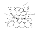
- the electrochemical cell current collector 1 includes a skeleton 2 and hollow pores 3.
- the skeleton 2 is a porous metal formed by sintering, is formed of a sintered body in which a plurality of metal particles 5 are bonded, and has a three-dimensional network structure.
- the metal forming the skeleton 2 aluminum, nickel, copper, stainless steel, or the like can be used.
- the hollow holes 3 are formed in a region delimited by the skeleton 2 and exist innumerably in the current collector 1 for electrochemical cells.
- the hollows 3 are communication holes in which the internal spaces are connected, and liquid or gas can flow through the current collector 1 for electrochemical cells through the hollows 3.
- the current collector 1 for an electrochemical cell is schematically shown, and therefore, the hollow pore 3 is drawn so as to be independent of other hollow pores 3 for convenience.
- Such hollow holes 3 form a slurry containing fine metal powder, a water-soluble binder, a surfactant, a foaming agent, and water when the current collector 1 for an electrochemical cell is manufactured as described later.
- the foaming agent in the sheet made in this manner is foamed to form foam, the slurry is dried, and the foam is removed in the process of sintering.
- the hollow 3 is not a naturally formed space such as a space formed between metal particles in the process of filling the metal particles, for example, a foaming agent as described above. It is an intentionally formed space that is formed by foaming to form bubbles in the slurry and removing the bubbles.
- the hollow 3 is formed in a spherical shape because the foaming agent is formed by foaming into a spherical bubble.
- the spherical shape here does not mean only a true sphere, but also includes a sphere in which a part of the spherical surface is a flat surface like a polyhedron, and a sphere whose cross section is an ellipse.
- the inner surface of the hollow 3 is covered with the resin composition 4.
- the inner surface of the hollow 3 is the surface of the skeleton 2 exposed in the internal space of the hollow 3, and the surface of the skeleton 2 is covered with the resin composition 4.
- polyvinylidene fluoride PVDF
- PE polyethylene
- PP polypropylene
- PS polystyrene
- ABS resin acrylic resin
- PMMA polyvinyl chloride
- PA polyamide
- POM polyacetal
- PC polycarbonate
- PET polyethylene terephthalate
- PPO polyphenyline oxide
- PBI polybenzimidazole
- PAI polyethersulfone
- PSU polytetrafluoroethylene
- PTFE polytetrafluoroethylene
- UP epoxy resin
- EP polyvinyl alcohol
- PVP polyvinyl pyrrolidone
- PEO polyethylene oxide
- PEO polyacrylonitrile butadiene
- the resin composition 4 may be a conductive resin such as polyacetylene, polyphenylene vinylene, polypyrrole, polythiophene, polyaniline, polyphenylene sulfide. These resins are examples of resins that can be used to form the resin composition 4. You may form the resin composition 4 using resin other than the above.
- the resin composition 4 may be formed using one type of resin, or may be formed by mixing a plurality of types of resins.
- the skeleton 2 will be described in more detail.
- the skeleton 2 is formed of a sintered body in which a plurality of metal particles 5 are directly bonded.
- the diameter of the void 6 is determined depending on the average particle diameter of the metal particles 5 and is not more than twice the average particle diameter of the metal particles 5.
- the resin composition 4 enters a small gap 6 having a diameter that is not more than twice the average particle diameter of the metal particles 5, so that more metal particles 5 are the resin composition 4.
- the metal particles 5 that are covered and strongly bonded to the adjacent metal particles 5 are increased, and the strength of the electrochemical cell current collector 1 can be further improved.
- the maximum diameter of a sphere that can be inserted into the gap 6 is defined as the diameter of the gap 6.
- the average particle size of the metal particles 5 was obtained by measuring the particle size distribution by a laser diffraction method.
- the diameter of the gap 6 was obtained from the measurement results obtained by a scanning electron microscope (Scanning-Electron-Microscope: SEM) and a three-dimensional CT scanner that photographed the surface or cross section of the skeleton 2.
- gap 6 measured about 30 space
- the metal particles 5 exposed on the surface of the skeleton 2 are covered with the resin composition 4.
- the resin composition 4 has entered the inside of the gap 6, and the surface of the metal particles 5 exposed in the internal space of the gap 6 is also covered.
- the resin enters between the metal particles 5 the metal particles 5 are bonded via the resin composition 4 in addition to the direct bonding between the metal particles 5.
- the skeleton 2 is covered with the resin composition 4 not only on the surface but also inside.
- the resin composition 4 is formed thicker on the uppermost metal particles 5 of the skeleton 2 than on the metal particles 5 exposed in the voids 6 inside the skeleton 2. Further, not all the gaps 6 are filled with the resin composition 4, and some of the gaps 6 have spaces inside.
- the current collector 1 for an electrochemical cell is prepared by dissolving an active material, a binder, a conductive auxiliary agent, and the like in a solvent (for example, N-methyl-2-pyrrolidone or water).
- a solvent for example, N-methyl-2-pyrrolidone or water.
- the applied electrode slurry (a positive electrode slurry containing a positive electrode active material or a negative electrode slurry containing a negative electrode active material) is applied, and the positive electrode mixture or the negative electrode mixture is filled in the hollow pores 3 and dried. Holds active material. In the hollow 3, the active material is bound to the skeleton 2 via a binder.
- an electrode slurry may be applied to the surface of the electrochemical cell current collector 1 to produce a composite electrode on the surface of the electrochemical cell current collector 1.
- the resin composition 4 is formed of the same resin as the binder.
- the current collector for an electrochemical cell is used for the positive electrode of a lithium ion secondary battery and PVDF is to be used as the binder of the positive electrode mixture
- the current collector for electrochemical cell 1 is PVDF as the resin composition 4. It is desirable to contain.
- the current collector 1 for an electrochemical cell when the positive electrode mixture is dried by heating and the active material is bound to the skeleton 2, PVDF as a binder is directly bound to the skeleton 2 or PVDF (binder ) And a resin composition 4 made of PVDF (the same resin as the binder), so that the same resin is easily bonded and strongly bonded. . Further, when the binder and the resin composition 4 are the same resin, the binder and the resin composition 4 are bonded together by being dissolved by heat, so that they are more strongly bound. Therefore, when used as an electrode of a lithium ion secondary battery, the current collector 1 for electrochemical cells can carry the active material more strongly and can suppress the falling off of the active material.
- the solvent for example, N-methyl-2-pyrrolidone
- the active material can be brought closer to the skeleton 2, so that the active material is supported in the vicinity of the skeleton 2 as compared with the case where the resin composition 4 is formed of another resin that is not soluble in the solvent. it can.
- the binder is made of the same resin. And the resin composition 4 are easily bonded, and are firmly bonded by heat.
- the porosity of the electrochemical cell current collector 1 is desirably 70% or more.
- the porosity means the ratio of the volume of the space in the electrochemical cell current collector 1 to the total volume of the electrochemical cell current collector 1.
- the space means the remaining portion of the hollow pore 3 and the void 6 where the resin composition 4 does not exist.
- the porosity is 70% or more, the current collector 1 for electrochemical cells has a small amount of the resin composition 4 contained in the hollow pores 3, and when used as an electrode of an electrochemical cell, the voids are eliminated. The decrease in the amount of active material carried by the pores 3 containing the resin composition 4 is small, and the decrease in the discharge capacity is small.
- the porosity of the electrochemical cell current collector 1 was determined by Archimedes' method by measuring the air mass and underwater mass of the electrochemical cell current collector 1.
- Such an electrochemical cell current collector 1 desirably contains the resin composition 4 in an amount of 0.1 to 200 wt% of the mass of the skeleton 2.
- the content of the resin composition 4 is 0.1 to 200 wt% of the mass of the skeleton 2
- the hollow pores 3 are not blocked by the resin composition 4, and the air in the current collector 1 for an electrochemical cell Gas flow can be ensured.
- the thickness of the resin composition 4 does not become too thick, electroconductivity and heat conductivity can be hold
- the current collector 1 for electrochemical cells preferably contains the resin composition 4 in an amount of 0.1 to 100 wt% of the mass of the skeleton 2.
- the current collector 1 for an electrochemical cell is improved in strength and has a low content of the resin composition 4 so that the electrical conductivity does not decrease, and when used for an electrode of an electrochemical cell, the decrease in discharge capacity is further suppressed.
- the cycle characteristics can be improved.
- the current collector 1 for an electrochemical cell contains the resin composition 4 in an amount of 1 to 10 wt% of the mass of the skeleton 2.
- the strength of the current collector 1 for electrochemical cells is improved and the amount of decrease in conductivity of the current collector 1 for electrochemical cells is even smaller. Therefore, when the current collector 1 for an electrochemical cell is used for an electrode of an electrochemical cell, it is possible to further suppress a decrease in discharge capacity and improve cycle characteristics.
- the thickness of the resin composition 4 covering the inner surface of the hollow 3 is preferably 0.05 to 100 ⁇ m.
- the thickness of the resin composition 4 is 0.05 to 100 ⁇ m, the hollow pores 3 are not blocked by the resin composition 4 and air and gas flow of the current collector 1 for electrochemical cells can be secured. Therefore, it is possible to maintain conductivity and thermal conductivity, and when used for an electrode of an electrochemical cell, it is possible to improve cycle characteristics while suppressing a decrease in discharge capacity.
- the resin composition 4 thicker than 100 ⁇ m adheres, a problem of blocking a part of the hollow 3 in the electrochemical cell current collector 1 occurs. Accordingly, the strength of the current collector 1 for an electrochemical cell is improved while more reliably having air permeability and metal characteristics.
- a more preferable range for improving the strength while ensuring air permeability and suppressing a decrease in conductivity is 0.1 to 10 ⁇ m.
- the thickness of the resin composition 4 is the distance from the surface of the metal particle 5 exposed in the internal space of the hollow 3 to the outermost surface of the resin composition 4 covering the surface of the metal particle. Measurements were made at 30 locations using a photomicrograph of a cross section of the current collector 1, and the average value was calculated.
- Manufacturing method of current collector for electrochemical cell includes (1) a step of producing skeleton 2 and (2) a step of coating resin composition 4. Consists of. These steps are described in detail below.
- Step of preparing skeleton 2 First, a metal fine powder, a water-soluble binder, a surfactant, and a foaming agent are mixed in water to prepare a slurry. Next, by a doctor blade method, the slurry is thinly applied onto a pet film and formed into a sheet shape. The molded sheet is heated to a predetermined temperature, and dried while forming bubbles on the sheet with a foaming agent. Then, by sintering in a non-oxidizing atmosphere (for example, inert atmosphere, reducing atmosphere) at a predetermined temperature, a sintered body in which a plurality of metal particles 5 are bonded is formed, and the sintered body is formed. Skeleton 2 is obtained.
- a non-oxidizing atmosphere for example, inert atmosphere, reducing atmosphere
- a resin solution is prepared by dissolving a resin in a solvent using a mixer so as to have a predetermined concentration. Thereafter, the skeleton 2 is immersed in the resin solution for a predetermined time. The skeleton 2 immersed in the resin solution is dried at a predetermined temperature for a predetermined time to obtain the current collector 1 for an electrochemical cell in which the skeleton 2 is covered with the resin composition 4.
- the current collector 1 for an electrochemical cell is formed by foaming of a foaming agent, and a skeleton 2 having a three-dimensional network structure formed by bonding metal particles 5 by sintering, and foaming of the foaming agent. And a foamed metal having hollow pores 3 present in a region delimited by the skeleton 2, and a resin composition 4 that covers the surface of the skeleton 2 and is contained in the void 6.
- content of the resin composition 4 of the electrical power collector 1 for electrochemical cells can be adjusted by changing the mass of the resin in the solvent which melt
- the mass of the resin in the solvent is changed, the viscosity of the resin solution changes, and the manner in which the resin composition 4 adheres to the skeleton 2 changes.
- the resin solution When the viscosity of the resin solution is low, the resin solution tends to soak into the gaps 6 between the metal particles 5 of the skeleton 2, and the resin composition 4 tends to adhere to the metal particles 5 exposed in the gaps 6.
- concentration of a resin solution since the density
- the viscosity of the resin solution When the viscosity of the resin solution is further increased, the resin solution is less likely to enter the gaps 6 between the metal particles 5, and the resin composition 4 tends not to adhere to the metal particles 5 exposed in the gaps 6. And the resin composition 4 tends to adhere thickly to the inner surface of the hollow 3. In this case, the content of the resin composition 4 tends to be high with respect to the mass of the skeleton 2 of the current collector 1 for electrochemical cells.
- the electrochemical cell current collector 1 includes the skeleton 2 formed by sintering the metal particles 5 and the hollow pores 3 formed by the skeleton 2. It comprised so that it might have the resin composition 4 to cover.
- the electrochemical cell current collector 1 absorbs part of the force applied to the skeleton 2 by the expansion and contraction of the resin composition 4 when a force is applied to the electrochemical cell current collector 1.
- the force required to break the current collector 1 for chemical cells increases, and the strength increases.
- the electrochemical cell current collector 1 is reinforced by covering the skeleton 2 with the resin composition 4, the electrochemical cell current collector 1 has characteristics as an electrochemical cell current collector. The strength of the electric body 1 can be improved and the occurrence of chipping can be suppressed.
- the electrochemical cell current collector 1 has a skeleton 2 having a plurality of metal particles 5 and voids 6 formed between the metal particles 5, and the resin composition 4 is contained in the voids 6. By doing so, the surfaces of the metal particles 5 exposed in the voids 6 are covered with the resin composition 4 so that the bonds between the metal particles 5 are strengthened and the inside of the skeleton 2 is reinforced, and the current collector for the electrochemical cell 1 strength can be improved.
- the surface of the skeleton 2 is reinforced in addition to the inside of the skeleton 2 by making the inner surface of the hollow pore 3 covered with the resin composition 4 in the current collector 1 for electrochemical cells, The strength of the electrochemical cell current collector 1 can be further improved.
- the lithium ion secondary battery of this embodiment is equipped with the electrode (a positive electrode and a negative electrode) using the collector 1 for electrochemical cells of this embodiment, the shrinkage
- a mixture of metal powder and inorganic powder was pressed at 2 to 7 ton / cm 2 and then sintered at 800 to 1150 ° C. to form a metal porous body.
- the density of the sintered metal porous body is as high as 5.15 to 6.19 g / cm 3 and the porosity is as low as 21.1 to 34.1%.
- the true density of iron is 6.98 g / cm 3.
- the density of the conventional metal porous body is The value is close to the true density of iron, which is consistent with the low porosity.
- the true density of Ni is 8.91 g / cm 3
- the density of the conventional metal porous body is a value close to the true density of Ni.
- the strength of the metal porous body was maintained by increasing the density of the metal porous body and decreasing the porosity.
- a resin is filled into the pores of such a porous metal body having a low porosity, in order to adjust the air permeability of the metal porous body.
- the porosity of the foam metal of the current collector (metal porous body) 1 for electrochemical cells is desirably 70% or more.
- the density of the foam metal of the current collector for an electrochemical cell when the metal particles 5 made of iron are used is less than 2.09 g / cm 3 , and the electricity when the metal particles 5 made of Ni are used.
- the density of the foam metal of the current collector for the chemical cell is less than 2.67 g / cm 3 , and the density of the foam metal of the current collector for the electrochemical cell is lower than that of the conventional porous metal body.
- the density of the electrochemical cell current collector in the case of using the metal particles 5 composed of Al becomes 0.81 g / cm less than 3 is 30% of the true density of 2.7 g / cm 3 of Al.
- the density of the foamed aluminum with a porosity of 94% is very low at 0.16 g / cm 3. Even if the current collector 1 contains a large amount of the resin composition 4 at a rate of 200 wt% with respect to the mass of the skeleton 2, the density of the current collector 1 for electrochemical cells is as low as 0.48 g / cm 3. .
- the current collector 1 for an electrochemical cell has a resin composition 4 covering the void 6 by covering the skeleton 2 of a three-dimensional network structure of a foam metal having low density and low strength with the resin composition 4. It is contained and the strength can be improved while the density remains low, that is, the porosity remains high.
- the conventional porous metal body is formed by sintering a metal powder pressed and hardened at a high pressure, and has a low porosity of about 20 to 30%. It is considered that the voids between the metal particles are crushed and the number of voids is small. As a result, it is considered that closed pores and voids isolated from other pores and voids are formed in the metal porous body.
- the closed pores and voids contain a gas such as air, but since the gas or liquid cannot flow in, the resin composition cannot flow.
- the electrochemical cell current collector 1 of this embodiment has a three-dimensional network structure in which the skeleton 2 is formed by foaming of a foaming agent and the metal particles 5 are bonded by sintering. Since the open pores 3 are formed by foaming of the foaming agent and are not pressed at the time of forming the foam metal, there are few closed hollow pores 3 and voids 6, and the resin in the hollow pores 3 and voids 6 is resinous. It is easy to pour the composition 4.
- the current collector 1 for an electrochemical cell does not include the closed hollow 3 and void 6, so the resin composition 4
- a gas such as air in the hollow hole 3 or the gap 6 can flow out into the hollow hole 3 or the gap 6 communicating with the hollow hole 3 or the gap 6. Therefore, the current collector 1 for an electrochemical cell can easily flow the resin composition 4 into the hollows 3 and the voids 6 without locally forming a portion not containing the resin composition 4 in the skeleton 2.
- the resin composition 4 is easily impregnated into the voids 6 of the entire skeleton 2.
- the porosity of the foam metal is less than 70%, closed hollow pores 3 and voids 6 may be formed, and the resin composition 4 is formed in the closed hollow voids 3 and voids 6. Even if it is used as a current collector for an electrochemical cell, the active material cannot be held in the closed hollow 3.
- the present invention is not limited to the above-described embodiment, and can be appropriately changed within the scope of the gist of the present invention.
- the case where the resin composition 4 is included in the gap 6 between the metal particles 5 of the skeleton 2 and the inner surface of the hollow pore 3 is covered with the resin composition 4 has been described. Is not limited to this.
- the current collector 1 for an electrochemical cell if the void 6 contains the resin composition 4 and the surface of the metal particles 5 is covered with the resin composition in the void 6, the inner surface of the hollow 3 The resin composition 4 may not be covered.
- Such a current collector 1 for an electrochemical cell can be produced by immersing the skeleton 2 in a resin solution having a relatively low viscosity.
- the content of the resin composition 4 is changed by adjusting the amount of the resin added to the solvent when preparing the resin solution and changing the viscosity of the resin solution.
- the content of the resin composition 4 of the current collector 1 for an electrochemical cell can be changed by changing the molecular weight of the resin.
- the viscosity of the resin solution can be increased and the content of the resin composition 4 can be increased.
- the elastic strength of the resin composition 4 is increased, and the strength of the electrochemical cell current collector 1 is further improved.
- PVDF having an average molecular weight of 280,000 g / mol for example, PVDF # 1100 manufactured by Kureha Co., Ltd.
- PVDF having an average molecular weight of 1 million g / mol for example, PVDF # 7300 manufactured by Kureha Co., Ltd.
- the strength can be increased with the same amount of resin.
- the skeleton 2 is immersed in the resin solution and coated with the resin composition 4, but the present invention is not limited to this.
- the skeleton 2 in the step of coating the resin composition 4, the skeleton 2 is put into a vacuum container, the resin solution is poured into the container in a vacuum, the skeleton 2 is immersed in the resin solution, and then returned to atmospheric pressure.
- the skeleton 2 may be coated with the resin composition 4.
- more resin composition 4 can be contained in the skeleton 2.
- the gas contained in the fine gaps 6 between the metal particles 5 that are difficult to escape under the atmosphere also escapes, and the resin composition 4 enters the gaps 6. .
- the resin composition 4 when returning from vacuum to atmospheric pressure, the resin composition 4 is more likely to enter the void 6 inside the skeleton 2. Therefore, the content of the resin composition 4 increases.
- the resin solution may be applied to the outermost surface of the skeleton 2 by a comma roll coater or a die coater, and the resin solution is immersed into the skeleton 2 from the outermost surface, and the skeleton 2 is coated with the resin composition 4. Good.
- the content of the resin composition 4 can be adjusted by adjusting the discharge amount of the resin solution.
- the resin solution may be applied to the outermost surface of the skeleton 2 by a spray device or the like, and the resin solution may be immersed into the skeleton 2 from the outermost surface, and the skeleton 2 may be coated with the resin composition 4.
- content of the resin composition 4 can be adjusted by adjusting the injection amount of the resin solution.
- a slurry in which metal fine powder, a water-soluble binder, a surfactant, and a foaming agent are mixed with water is formed into a sheet, and the foaming agent is foamed in that state, and then sintered.
- the skeleton 2 is formed has been described, but the present invention is not limited to this, and the skeleton 2 can be produced using beads, for example.
- beads made of a resin such as polyethylene and metal powder made of a metal such as copper, nickel, and aluminum are weighed to a predetermined volume ratio and put into a container, and then a predetermined amount.
- the binder is also put into the container.
- alumina (Al 2 O 3 ) balls having a diameter of 5 mm are put into the container, and then the container is covered and ball mill mixing is performed. Subsequently, the mixed powder is passed through a sieve having a mesh size of 3 mm, and the alumina balls are taken out from the mixed powder.
- the mixed powder from which the alumina balls are taken out is put into a mold and pressed to produce a green compact.
- the green compact is placed in a belt furnace capable of controlling the atmosphere, and the green compact is heated in the air atmosphere to evaporate the resin component and remove the beads.
- the framework 2 can be produced by sintering the green compact in an inert gas atmosphere such as argon in the belt furnace.
- the hollow pores 3 are formed in the space where the beads existed by evaporating and removing the resin that forms the beads present in the green compact. .
- the hollow 3 is a space formed intentionally formed by removing the beads from the green compact.
- the hollow hole 3 has a shape similar to that of a bead, and has a spherical shape when a spherical bead is used.
- the spherical shape here does not indicate only a true spherical shape but also includes those in which a part of the sphere is distorted or bent.
- the electrochemical cell current collector 1 Since the electrochemical cell current collector 1 has increased strength while maintaining high air permeability, conductivity, and thermal conductivity, it is not a lithium ion secondary battery. Moreover, it can be used for electrodes of other electrochemical cells such as lithium ion capacitors (LIC), electric double layer capacitors (EDLC), and nickel metal hydride batteries.
- LIC lithium ion capacitors
- EDLC electric double layer capacitors
- nickel metal hydride batteries nickel metal hydride batteries.
- the EDLC includes a positive electrode, a negative electrode, and a separator sandwiched between the positive electrode and the negative electrode.
- the positive electrode, the negative electrode, and the separator are immersed in an electrolytic solution containing, for example, ethylene carbonate (EC), diethyl carbonate (DEC), ethyl methyl carbonate (EMC), dimethyl carbonate (DMC), or the like.
- the positive electrode and the negative electrode have the same structure, and are a collection for an electrochemical cell formed of an electrode mixture containing an active material such as natural graphite (for example, activated carbon) and a binder such as PVDF or PTFE, and metal particles 5 made of aluminum. And electric body 1.
- the composite material may further contain a conductive additive such as acetylene black, ketjen black, and carbon nanotube.
- the lithium ion capacitor includes a positive electrode, a negative electrode, and a separator sandwiched between the positive electrode and the negative electrode.
- the positive electrode, the negative electrode, and the separator are, for example, LiPF 6 , LiBF 4 , LiClO 4 or the like in a non-aqueous solvent including ethylene carbonate (EC), diethyl carbonate (DEC), ethyl methyl carbonate (EMC), dimethyl carbonate (DMC), and the like. It is immersed in an electrolyte mixed with lithium salt.
- the positive electrode has a positive electrode mixture containing an active material such as natural graphite and a binder such as PVDF and PTFE, and a current collector 1 for an electrochemical cell formed of metal particles 5 made of aluminum. It has the negative electrode compound material containing active materials, such as graphite, and binders, such as styrene, butadiene, rubber, and the collector 1 for electrochemical cells formed with the metal particle 5 which consists of copper.
- the composite material may further contain a conductive additive such as acetylene black, ketjen black, and carbon nanotube, and a thickener such as carboxymethylcellulose.
- the electrochemical cell using the electrochemical cell current collector 1 as an electrode can prevent the electrode from being chipped during the manufacturing process, and can prevent the electrochemical cell from being internally short-circuited by a broken piece of the electrode.
- an electrochemical cell using the electrochemical cell current collector 1 as an electrode has a resin composition 4 that is stronger than a conventional material without increasing the metal filling rate of the electrochemical cell current collector 1.
- the porosity can be increased as compared with the conventional case, the electrode can have more active materials, and the capacity can be improved.
- the electrochemical cell using the electrochemical cell current collector 1 as an electrode improves the tensile strength of the electrochemical cell current collector 1, and the electrode mixture is applied to the electrochemical cell current collector 1.
- the electrode mixture can be applied without breaking the electrochemical cell current collector 1, and the production yield can be increased. Can be increased.
- Example (Example 1) The current collector for an electrochemical cell of the present invention was produced and its characteristics were evaluated. First, the cross section of the electrochemical cell current collector was observed with an electron microscope, and the structure was evaluated. Next, the tensile strength of the produced current collector for an electrochemical cell was measured, and the strength was evaluated.
- Example 1 (1) Production of current collector for electrochemical cell As Example 1, foamed aluminum was used, and 0.1, 1, 5, 10, 50, 100, 200 wt% with respect to the mass of the skeleton formed of aluminum. A current collector for an electrochemical cell containing PVDF was produced. Since the production method is the same except that the amount of the resin added to the solvent is changed, a current collector for an electrochemical cell containing 0.1 wt% PVDF with respect to the mass of the foamed aluminum will be described as an example. .
- the molded sheet was dried while heating to 50 ° C. to form bubbles in the sheet. Thereafter, the molded body is peeled off from the pet film, placed on an alumina plate, sintered in an argon atmosphere at 500 ° C., and foamed aluminum (aluminum sintered body) having a porosity of 94% and a thickness of 0.4 mm is obtained. Obtained.
- the produced foamed aluminum was cut into a size of 10 mm in width and 30 mm in length to prepare a skeleton formed of aluminum.
- Particulate PVDF powder (PVDF # 7300 manufactured by Kureha Co., Ltd.) is dissolved in N-methyl-2-pyrrolidone (NMP) with a mixer to a mass concentration of 3 wt%, and the viscosity is 0.1 Pa ⁇ s.
- NMP N-methyl-2-pyrrolidone
- a resin solution of PVDF was prepared. Thereafter, the prepared skeleton was immersed in the resin solution for 3 minutes. The soaked skeleton was dried at 180 ° C. for 30 minutes to produce a current collector for an electrochemical cell containing PVDF at a ratio of 0.1 wt% with respect to the weight of the skeleton.
- PVDF powder PVDF # 7300 manufactured by Kureha Co., Ltd.
- a PVDF resin solution having a viscosity of 5 Pa ⁇ s was prepared.
- the thickness of PVDF adhering to the skeleton surface is 0.05 ⁇ m, and PVDF is added at a ratio of 200 wt%.
- the thickness of the PVDF was 100 ⁇ m.
- FIG. 3A is an SEM photograph of a cross section of a current collector for an electrochemical cell having a PVDF content of 5 wt% of the mass of the skeleton
- FIG. 3B is a cross section of the current collector for an electrochemical cell having a PVDF content of 50 wt% of the mass of the skeleton. It is.
- the white line shown at the bottom of the drawing indicates that the length of the white line is 100 ⁇ m in the drawing.
- the skeleton 2 of the current collector for an electrochemical cell is formed by combining a plurality of metal particles 5. It can be seen that the gap 6 between the metal particles 5 has a black portion and a dark gray portion, and the resin composition 4 (PVDF) is present in the dark gray portion. In addition, the part which has become black is a part in which PVDF of the space
- PVDF resin composition 4
- the electrochemical cell current collector (FIG. 3B) having a PVDF content of 50 wt% relative to the mass of the skeleton is covered with the resin composition 4 on the inner surface than the 5 wt% electrochemical cell current collector (FIG. 3A). It can be seen that there are many hollows 3 in the inside. This is because the amount of PVDF in the resin solution at the time of production was larger in the collector for electrochemical cells having a PVDF content of 50 wt% of the mass of the skeleton, and the resin solution adhered to the inner surface of the hollow 3 It is thought that it is because it is easy to do.
- 4A and 4B are SEM photographs showing the enlarged metal particles 5 inside the skeleton 2. These SEM photographs were taken of the electrochemical cell current collector of the electrochemical cell current collector of Example 1 having a PVDF content of 5 wt% of the mass of the skeleton.
- the tensile force at the time of breaking was defined as tensile strength, and the value obtained by subtracting 10 mm, which is the initial value of the distance between chucks, from the distance between chucks at the time of breaking was defined as the elongation of the current collector for electrochemical cells.
- the tensile strength of the foamed aluminum used to produce the electrochemical cell current collector of Example 1 as Comparative Example 1 was also measured.
- the value obtained by subtracting 1 from the relative strength of the current collector for an electrochemical cell of Example 1 calculated as 1 was expressed as a percentage as the “strengthening rate” by the resin coating, and for the electrochemical cell depending on the strengthening rate.
- the strength of the current collector was evaluated.
- each of the electrochemical cell current collectors of Example 1 has a positive strengthening rate and improved strength.
- the skeleton is covered with the resin composition. Therefore, when the electrochemical cell current collector is pulled, the force applied to the skeleton by the expansion and contraction of the resin composition. As a part of the water is absorbed, the force applied to the electrochemical cell current collector is reduced. Furthermore, in the current collector for an electrochemical cell of Example 1, since the metal particles are covered with the resin composition, the bond between the metal particles becomes strong. As a result, it is considered that the strength of the electrochemical cell current collector of Example 1 increased.
- the electrochemical cell current collector of Example 1 has a larger elongation at break than the electrochemical cell current collector of Comparative Example 1.
- the bond between the metal particles became strong as described above. Therefore, when the metal particle was not covered with the resin composition, the metal particles had a force enough to break the bond between the metal particles. Even if it takes, it is thought that the bond between the metal particles was not broken and the resin composition expanded and contracted.
- the current collector for an electrochemical cell of Example 1 has a higher strengthening rate and a greater elongation at break as the resin composition content increases. It is considered that when the amount of the resin composition increases, the force absorbed by the resin composition increases and the bond between the metal particles becomes stronger.
- Example 2 The tensile strength of the electrochemical cell current collector was evaluated by changing the resin composition.
- the produced current collector for the electrochemical cell of Example 2 uses foamed aluminum having a width of 10 mm, a length of 30 mm, a thickness of 0.4 mm, and a porosity of 94%, and is 5 wt% of the mass of the skeleton formed of aluminum. Contains a resin composition.
- the method for producing the porous metal is the same as in Example 1.
- Resin used for the current collector for the electrochemical cell of Example 2 is polyvinylidene fluoride, polyethylene, polypropylene, polystyrene, acrylonitrile / butadiene / styrene copolymer synthetic resin, acrylic resin, polyvinyl chloride, polyamide, polyacetal, polycarbonate, Polyethylene terephthalate, polyphenyline oxide, polybenzimidazole, polyamideimide, polyether sulfone, polysulfone, polytetrafluoroethylene, phenol resin, urea resin, melamine resin, unsaturated polyester resin, epoxy resin, polyvinyl alcohol, polyvinyl pyrrolidone, Polyethylene oxide, polyacrylonitrile, and conductive resins such as polyacetylene, polyphenylene vinylene, polypyrrole, polythiophene, polyaniline Is a polyphenylene sulfide.
- the strength of the current collector for an electrochemical cell is a tensile value obtained by subtracting 1 from the value obtained by dividing the measured tensile strength at break of Example 2 by the tensile strength at break of Comparative Example 2. It was defined as the degree of improvement in strength and evaluated using that. Table 2 shows that the degree of improvement in tensile strength is 30% or more, ⁇ 10% or more and less than 30%, ⁇ , 1% or more and less than 10%, ⁇ or less than 1%. It is shown as The tensile strength at break was measured by the same method as in Example 1.
- Example 2 As shown in Table 2, it can be seen that the electrochemical cell current collector of Example 2 has improved tensile strength. It turns out that the intensity
- Example 3 In an electrochemical cell, an electrode mixture is applied to a current collector for an electrochemical cell by a comma roll coater at the time of manufacture. At this time, the current collector for an electrochemical cell is applied to a cylindrical roll and applied with a tensile force. Therefore, in Example 3, the strength of the current collector for an electrochemical cell was evaluated by the following method which is closer to the actual method for producing an electrochemical cell.
- a current collector for an electrochemical cell having a thickness of 1 mm, a width of 300 mm, and a length of 2 m is prepared, and both ends in the major axis direction of the electrochemical cell current collector are bonded together by welding, and an endless electrochemical cell having a length of about 1 m.
- a current collector for a cell was produced.
- Two metal rolls (diameter 10 cm) having a cylindrical shape and rotating around the central axis of the cylinder were arranged with an interval of 1 m.
- the endless electrochemical cell current collector was placed on two metal rolls, and one metal roll was rotated by a motor so that the electrochemical cell current collector could be rotated.
- the amount of decrease in the mass of the current collector for electrochemical cell after rotating the current collector for electrochemical cell 500 times at a speed of 10 m / min is measured, and the amount of decrease in mass is determined as the initial amount for current collector for electrochemical cell. It was expressed as a ratio (percentage) to the mass of the electric body, and the strength was evaluated.
- Example 3 a foamed aluminum having a porosity of 85%, a current collector for an electrochemical cell containing PVDF as a resin composition in a proportion of 5 wt% with respect to the mass of the skeleton formed of aluminum, and the porosity Using 90% foamed copper, a current collector for an electrochemical cell containing SBR as a resin composition at a ratio of 2 wt% with respect to the mass of the skeleton formed of copper was produced, and the strength was evaluated by the above method. did.
- a current collector for an electrochemical cell using foamed copper was produced by the following method. First, 200 g of copper fine powder (manufactured by Aldrich, average particle size 10 ⁇ m) was mixed with 6 g of a water-soluble surfactant (manufactured by Kao Corporation, product name: Emar, product number 20T) and 500 mL of water to prepare a slurry.
- a water-soluble surfactant manufactured by Kao Corporation, product name: Emar, product number 20T
- the prepared slurry was thinly applied onto a pet film (manufactured by Toray Industries Inc., product name: Treffan, product number 2500T) by a doctor blade method, and formed into a sheet.
- the film was dried while forming bubbles on the molded sheet by heating to 50 ° C.
- sintering was performed in an argon atmosphere at about 500 ° C. to form foamed copper having a porosity of 90%, a thickness of 1 mm, a width of 300 mm, and a length of 2 m, thereby producing a skeleton formed of copper.
- a slurry for preparing a current collector for an electrochemical cell is prepared.
- SBR SBR: CMC is 1: 1 by weight.
- an aqueous solution in which CMC was dissolved was further added to prepare a resin solution having a total mass concentration of SBR and CMC of 10 wt%.
- the skeleton was immersed in a resin solution for 3 minutes and dried at 110 ° C. for 90 minutes to produce a current collector for an electrochemical cell containing SBR at a ratio of 2 wt% with respect to the weight of the skeleton.
- Comparative Example 3 For comparison, as Comparative Example 3, the strength of foamed aluminum and foamed copper used in Example 3 was evaluated by the above method. These results are shown in Table 3.
- the current collector for the electrochemical cell of Example 3 Since the mass reduction amount of the current collector for the electrochemical cell of Example 3 is 0, it can be seen that the current collector for the electrochemical cell is not damaged. On the other hand, the current collector for the electrochemical cell of the comparative example has a mass reduction amount of 0, so that the current collector for the electrochemical cell is missing, and the piece of the current collector for the electrochemical cell is dropped and the mass is reduced. I understand. Thus, it was confirmed that the current collector for an electrochemical cell of the present invention can improve strength and contain chips by including the resin composition 4.
- Example 4 As Example 4, a lithium ion secondary battery using the current collector for an electrochemical cell of the present invention as a positive electrode was produced and its characteristics were evaluated.
- a foamed aluminum having a porosity of 94% and a thickness of 300 ⁇ m was produced in the same manner as in Example 1, and the aluminum foam was cut into a size of 30 mm in width and 25 mm in length to produce a skeleton formed of aluminum. .
- a current collector for an electrochemical cell containing 0.1, 1, 5, 10, 50, 100, and 200 wt% PVDF with respect to the mass of the skeleton was produced by the same method as in Example 1.
- the content ratio of PVDF was changed by adjusting the amount of resin charged into the solvent.
- LiCoO 2 (LCO) as an active material, PVDF as a binder, and acetylene black (AB) as a conductive assistant were weighed so that the mass ratio was 98: 1: 1. Thereafter, the weighed PVDF was added to the solvent N-methyl-2-pyrrolidone (NMP) and stirred for 20 minutes. Further, LCO and AB were added and stirred to prepare a positive electrode slurry adjusted to a viscosity of 6 Pa ⁇ s.
- NMP N-methyl-2-pyrrolidone
- each electrochemical cell current collector was immersed in the positive electrode slurry for 5 minutes, and then the excess positive electrode slurry adhering to the surface was dropped with a spatula and dried at 120 ° C. for 1 hour to produce a positive electrode.
- natural graphite as an active material SBR as a binder, AB as a conductive additive, and CMC as a thickener were weighed so that the mass ratio was 97: 1: 1: 1.
- CMC is dissolved in water to prepare an aqueous solution with a concentration of 1%, and the aqueous solution, natural graphite and AB are put into a rotating / revolving hybrid mixer (model: ARE-310, manufactured by Shinky Corporation) and stirred for 10 minutes. did.
- a solution in which SBR was dispersed was added and stirred for 10 minutes. Thereafter, water was appropriately added and further stirred to prepare a negative electrode slurry having a viscosity adjusted to 800 mPa ⁇ s.
- a copper foil having a thickness of 10 ⁇ m is cut into the same shape as the positive electrode to produce a current collector for the negative electrode, and a negative electrode slurry is applied to one surface of the current collector for the negative electrode with a comma roll coater.
- a negative electrode mixture layer having a thickness of 300 ⁇ m was formed on the surface of the current collector by drying at a temperature of 1 ° C. for 1 hour to produce a negative electrode.
- a polyethylene separator having countless fine pores is sandwiched between the positive electrode and the negative electrode, and ethylene carbonate (EC), ethyl methyl carbonate (EMC), and dimethyl carbonate (DMC) are mixed at a volume ratio of 1: 1: 1.
- EC ethylene carbonate
- EMC ethyl methyl carbonate
- DMC dimethyl carbonate
- the lithium ion secondary battery of Example 4 in the form of a laminate cell was prepared by inserting into an aluminum laminate pack together with an electrolytic solution in which 1M LiPF 6 was added to the solvent mixed at a ratio and vacuum packing.
- the discharge capacity and capacity retention rate of the lithium ion secondary battery produced in this way were measured, and the characteristics of the lithium ion secondary battery were evaluated.
- the discharge capacity of the lithium ion secondary battery was measured.
- the discharge capacity is a constant current of 1 mA / cm 2 , 4.2 Vvs.
- the cut-off voltage is set to 3.0 V vs.
- Li / Li + was measured under two discharge conditions of 1C discharge and 0.2C discharge.
- the capacity retention rate (%) is the discharge capacity after the cycle test when the discharge capacity in the first cycle of the cycle test in which charging and discharging are repeated is 100.
- the capacity maintenance rate was calculated from the measurement results by measuring the discharge capacity before and after the cycle test by repeating the cycle test by repeating the charge and discharge for 100 cycles with 0.2C charge and 0.2C discharge as one cycle.
- the capacity retention rate is a value representing the cycle characteristics of the electrochemical cell, and the larger the value, the better the cycle characteristics, that is, the durability.
- Table 4 shows the discharge capacity obtained by changing the discharge rate of the lithium ion secondary battery of Example 4 and the capacity retention rate (%) after the cycle test.
- Comparative Example 4 a lithium ion secondary battery different from the lithium ion secondary battery of Example 4 only in that the foamed aluminum used for the electrochemical cell current collector of Example 4 was used as the positive electrode current collector.
- the discharge capacity and the capacity retention rate were measured in the same manner as in Example 4.
- Table 4 also shows the measurement results of the discharge capacity and capacity retention rate of Comparative Example 4.
- the value of the discharge capacity in Table 4 represents the value of the discharge capacity of each example and the comparative example at the time of 1C discharge when the value of the discharge capacity at the time of 0.2C discharge of Comparative Example 4 is taken as 100.
- the lithium ion secondary battery of Example 4 has a higher capacity retention rate and improved cycle characteristics as compared with the lithium ion secondary battery of Comparative Example 4.
- the current collector for an electrochemical cell is reinforced by containing a resin composition, the strength is improved, chipping can be suppressed, and the electrochemical cell current collector is subjected to shrinkage and expansion in the charge / discharge process of a lithium ion secondary battery. This is considered to be because the chipping of the current collector and the bond between the metal particles 5 were released and the electrical path was cut off.
- the current collector for an electrochemical cell of the present invention has improved strength and can improve the cycle characteristics of a lithium ion secondary battery when used as an electrode of a lithium ion secondary battery.
- the lithium ion secondary battery of Example 4 has a larger discharge capacity as the content of the resin composition is lower. This is because as the content of the resin composition increases, the electrical conductivity of the current collector for electrochemical cells decreases, causing an increase in the internal resistance of the lithium ion secondary battery, and the amount of active material that can be carried decreases. It is thought that it is because it does. Specifically, when the mass of the resin composition with respect to the mass of the skeleton is 0.1 to 200 wt%, the reduction in discharge capacity is small, and the mass of the resin composition with respect to the mass of the skeleton is 0.1 to 100 wt%. For example, the decrease in discharge capacity is smaller. In the case of 0.2C discharge, the decrease in discharge capacity is 0.
- the current collector for an electrochemical cell preferably contains 0.1 to 200 wt% of the resin composition relative to the mass of the skeleton, and contains 0.1 to 100 wt% of the resin composition relative to the mass of the skeleton. It was confirmed that it was more desirable to contain, and it was further desirable to contain 0.1 to 10 wt% of the resin composition with respect to the mass of the skeleton.
- Example 5 As Example 5, an EDLC using the current collector for an electrochemical cell of the present invention as an electrode was produced, and its characteristics were evaluated.
- Example 4 First, by the same method as in Example 4, the same size as that of the electrochemical cell current collector of Example 4, using foamed aluminum having a porosity of 94%, with respect to the mass of the skeleton formed of aluminum.
- Current collectors for electrochemical cells containing 0.1, 1, 5, 10, 50, 100, and 200 wt% PVDF were prepared.
- coconut shell activated carbon manufactured by Kuraray Chemical Co., Ltd., model number YP-50F
- PVDF as a binder
- AB as a conductive additive
- each electrochemical cell current collector was immersed in an electrode slurry for 5 minutes, and then the excess electrode slurry adhering to the surface was dropped with a spatula and dried at 120 ° C. for 1 hour to produce an electrode for EDLC. did.
- a cellulose separator having innumerable fine pores is sandwiched between two electrodes for EDLC, and tetraethylammonium tetrafluoroborate (N (C) as an electrolyte in propylene carbonate (PC) as a solvent.
- N (C) tetraethylammonium tetrafluoroborate
- PC propylene carbonate
- An electrolyte solution containing 1 mol of 2 H 5 ) 4 BF 4 ) was inserted into an aluminum laminate pack and vacuum packed to produce a laminate cell-like EDLC of Example 5.
- the capacitor is completed. The positive voltage is applied to the positive electrode and the negative voltage is applied to the negative electrode.
- the discharge capacity and capacity retention rate of the EDLC thus produced were measured, and the characteristics of the EDLC were evaluated.
- the discharge capacity is charged at a constant current of 2 mA / cm 2 , and after the voltage between the positive electrode and the negative electrode reaches 2.4 V, the cut-off voltage is set to 1 V, and the discharge conditions are 100 C discharge and 10 C discharge. It was measured.
- the capacity maintenance rate was calculated from the measurement result by measuring 50 C charge and 50 C discharge as one cycle, repeating charge and discharge for 10,000 cycles, measuring the discharge capacity before and after the cycle test.
- Table 5 shows the discharge capacity obtained by changing the discharge rate of the EDLC of Example 5 and the capacity retention rate (%) after the cycle test.
- Comparative Example 5 an EDLC different from the EDLC of Example 5 was produced only in that the foamed aluminum used for the electrochemical cell current collector of Example 5 was used as the current collector of each electrode. Similarly, the discharge capacity and the capacity retention rate were measured. Table 5 also shows the measurement results of the discharge capacity and capacity retention rate of Comparative Example 5.
- the value of the discharge capacity in Table 5 represents the value of the discharge capacity of each example and the comparative example at the time of 100C discharge when the value of the discharge capacity at the time of 10C discharge of Comparative Example 5 is set to 100.
- the EDLC of Example 5 has a higher capacity retention rate and improved cycle characteristics as compared with the EDLC of Comparative Example 5.
- the current collector for an electrochemical cell of the present invention has improved strength and can suppress chipping, and activated carbon from foamed aluminum considered to be due to thermal expansion and contraction associated with charge and discharge during the cycle by coating with PVDF. It is considered that a high capacity can be maintained because no desorption occurs.
- the cycle characteristics of the EDLC can be improved.
- the discharge capacity of the EDLC of Example 5 is larger as the content of the resin composition is lower. This is because as the content of the resin composition increases, the electrical conductivity of the current collector for the electrochemical cell decreases and causes an increase in the internal resistance of the EDLC, and the amount of the active material that can be supported also decreases. it is conceivable that.
- the mass of the resin composition with respect to the mass of the skeleton is 0.1 to 200 wt%
- the reduction in discharge capacity is small
- the mass of the resin composition with respect to the mass of the skeleton is 0.1 to 100 wt%.
- the decrease in discharge capacity is smaller, and in the case of 10C discharge, the decrease in discharge capacity is 0 or 1.
- the current collector for an electrochemical cell preferably contains 0.1 to 200 wt% of the resin composition relative to the mass of the skeleton, and contains 0.1 to 100 wt% of the resin composition relative to the mass of the skeleton. It was confirmed that it was more desirable to contain, and it was further desirable to contain 0.1 to 10 wt% of the resin composition with respect to the mass of the skeleton.
- Example 6 As Example 6, a lithium ion capacitor using the current collector for an electrochemical cell of the present invention as a positive electrode and a negative electrode was produced, and its characteristics were evaluated.
- the size is the same as that of the electrochemical cell current collector of Example 5, and 0.1, 1, 5, 10, 50, 100, 200 wt% with respect to the mass of the skeleton.
- the electrode for lithium ion capacitors was produced, respectively, using the collector for electrochemical cells containing PVDF. The electrode was used as a positive electrode of a lithium ion capacitor.
- a foamed copper having a porosity of 70% and a thickness of 300 ⁇ m was produced in the same manner as in Example 3, and the foamed copper was cut into the same shape as the positive electrode to produce a skeleton formed of copper.
- a slurry for preparing a current collector for an electrochemical cell for a negative electrode of a lithium ion capacitor is prepared.
- SBR SBR: CMC is 1: 1 by weight.
- an aqueous solution in which CMC was dissolved was further added to prepare a resin solution having a total mass concentration of SBR and CMC of 2 wt% and a viscosity of 50 mPa ⁇ s.
- skeleton was immersed in the resin solution for 3 minutes.
- EC ethylene carbonate
- DEC diethyl carbonate
- EMC ethyl methyl carbonate
- LiBF 4 lithium tetrafluoroborate
- the discharge capacity and capacity retention rate of the lithium ion capacitor thus fabricated were measured to evaluate the characteristics of the lithium ion capacitor.
- the discharge capacity reached a constant current of 2 mA / cm 2 , and the discharge between the positive electrode and the negative electrode reached 4.0 V, and then the discharge was started.
- the cut-off voltage was 2 V, and the discharge conditions were 50 C discharge and 10 C discharge. It was measured.
- the capacity maintenance rate was calculated from the measurement result by measuring 50 C charge and 50 C discharge as one cycle, repeating charge and discharge for 10,000 cycles, measuring the discharge capacity before and after the cycle test.
- Table 6 shows the discharge capacity obtained by changing the discharge rate of the lithium ion capacitor of Example 6 and the capacity retention rate (%) after the cycle test.
- Comparative Example 6 the lithium ion capacitor of Example 6 only in that the foamed aluminum used for the electrochemical cell current collector of Example 6 was used as the positive electrode current collector and the foamed copper was used as the negative electrode current collector.
- a lithium ion capacitor different from the above was prepared, and the discharge capacity and the capacity retention rate were measured in the same manner as in Example 6.
- Table 6 also shows the measurement results of the discharge capacity and capacity retention rate of Comparative Example 6.
- the value of the discharge capacity in Table 6 represents the value of the discharge capacity of each example and the comparative example at the time of 50 C discharge when the value of the discharge capacity at the time of 10 C discharge of Comparative Example 6 is set to 100.
- the lithium ion capacitor of Example 6 has a higher capacity retention rate and improved cycle characteristics as compared with the lithium ion capacitor of Comparative Example 6.
- the current collector for an electrochemical cell of the present invention has improved strength and can suppress chipping, and can improve the cycle characteristics of a lithium ion capacitor when used as an electrode of a lithium ion capacitor.
- the lithium ion capacitor of Example 6 has a larger discharge capacity as the content of the resin composition is lower. This is because, as the content of the resin composition increases, the electrical conductivity of the current collector for the electrochemical cell decreases and causes an increase in the internal resistance of the lithium ion capacitor, and the amount of the active material that can be supported also decreases. It is thought that. Specifically, when the mass of the resin composition with respect to the mass of the skeleton is 0.1 to 200 wt%, the reduction in discharge capacity is small, and the mass of the resin composition with respect to the mass of the skeleton is 0.1 to 100 wt%. For example, the decrease in discharge capacity is smaller, and in the case of 10 C discharge, the decrease in discharge capacity is 0 or 3.
- the current collector for an electrochemical cell preferably contains 0.1 to 200 wt% of the resin composition relative to the mass of the skeleton, and contains 0.1 to 100 wt% of the resin composition relative to the mass of the skeleton. It was confirmed that it was more desirable to contain, and it was further desirable to contain 0.1 to 10 wt% of the resin composition with respect to the mass of the skeleton.
- Example 7 an EDLC using an electrode for a current collector for an electrochemical cell in which a skeleton produced using beads was covered with a resin composition and reinforced was used, and its characteristics were evaluated.
- beads and aluminum powder were weighed at a volume ratio of 80:20 and put into a plastic container. Specifically, spherical beads having an average particle diameter of 100 ⁇ m are poured 8 times in a 100 mL container into a 3 L plastic container, and aluminum powder having an average particle diameter of 10 ⁇ m (manufactured by Aldrich) is added in a 100 mL container. It was scooped twice and put into the plastic container. Thereafter, 35 g of polyvinyl alcohol (PVA) powder was charged as a binder into a plastic container charged with beads and aluminum powder.
- PVA polyvinyl alcohol
- the green compact is placed in a belt furnace that can control the atmosphere, the temperature in the furnace is raised to 350 ° C. over 5 hours in an air atmosphere, and the temperature in the furnace is maintained at 350 ° C. for 10 hours.
- the polyethylene of the beads in the green compact is evaporated to remove the beads.
- the inside of the belt furnace is set to an argon atmosphere, the temperature in the furnace is increased to 655 ° C. over 3 hours, the temperature in the furnace is maintained at 655 ° C. for 1 hour, and the temperature in the furnace is increased to 100 ° C. over 3 hours.
- An aluminum sintered body was produced by lowering and sintering the green compact.
- the produced aluminum sintered body had a thickness of 0.4 mm and a porosity of 70%.
- the aluminum sintered body was cut into a width of 10 mm and a length of 25 mm to prepare a skeleton formed of aluminum.
- the current collector for a cell was produced.
- the current collector for the electrochemical cell of Example 7 contained PVDF in a proportion of 1.6 wt% with respect to the mass of the skeleton.
- Example 7 Using the current collector for an electrochemical cell of Example 7 as a current collector for both positive and negative electrodes, an EDLC of Example 7 was produced under the same method and conditions as in Example 5. The discharge capacity and capacity retention rate (%) of the EDLC of Example 7 were measured by the same method and conditions as in Example 5, and the characteristics of the EDLC of Example 7 were evaluated.
- Comparative Example 7 instead of the electrochemical cell current collector of Example 7, a skeleton (aluminum sintered body) used for the production of the electrochemical cell current collector of Example 7 was used.
- An EDLC different from the EDLC of Example 7 was produced only in that it was used as a current collector for both the positive electrode and the negative electrode, and the discharge capacity and capacity retention rate were measured in the same manner as in Example 7.
- Table 7 shows the measurement results of the discharge capacity and capacity retention rate of Example 7 and Comparative Example 7.
- the value of the discharge capacity in Table 7 represents a value normalized by setting the value of the discharge capacity at the time of 10 C discharge of Comparative Example 7 to 100.
- the EDLC of Example 7 has a higher capacity retention rate and improved cycle characteristics than the EDLC of Comparative Example 7.
- the electrochemical cell current collector of Example 7 can suppress chipping due to improved strength, and is covered by PVDF, which is considered to be due to thermal expansion and contraction associated with charge and discharge during the cycle. It can be considered that a high capacity can be maintained because the desorption of activated carbon from the current collector can be suppressed.
- the electrochemical cell current collector is reinforced with a resin composition, so that the electrochemical cell current collector is The strength of the EDLC can be improved, and the cycle characteristics of the EDLC can be improved when used as an EDLC electrode.
Landscapes
- Chemical & Material Sciences (AREA)
- Engineering & Computer Science (AREA)
- Chemical Kinetics & Catalysis (AREA)
- Electrochemistry (AREA)
- General Chemical & Material Sciences (AREA)
- Materials Engineering (AREA)
- Power Engineering (AREA)
- Metallurgy (AREA)
- Organic Chemistry (AREA)
- Mechanical Engineering (AREA)
- Microelectronics & Electronic Packaging (AREA)
- Electric Double-Layer Capacitors Or The Like (AREA)
- Cell Electrode Carriers And Collectors (AREA)
Abstract
欠けが生じにくい電気化学セル用集電体、リチウムイオン二次電池、電気二重層キャパシタ及びリチウムイオンキャパシタを提供する。 本発明の電気化学セル用集電体1は、複数の金属粒子5が結合した焼結体で形成され、3次元網目構造をした骨格2と、骨格2によって区切られた領域に存在する中抜き細孔3と、骨格2内部の金属粒子5同士の間に形成された空隙6とを有し、少なくとも空隙6に樹脂組成物4を含み、中抜き細孔3同士は、液体や気体が流通するように内部空間が互いに連通しているので、金属粒子5同士の結合が強くなり骨格2の内部が補強され、電気化学セル用集電体1の強度を向上でき、欠けの発生を抑制できる。
Description
本発明は、電気化学セル用集電体、リチウムイオン二次電池、電気二重層キャパシタ及びリチウムイオンキャパシタに関する。
金属多孔質体は、無数の細孔を有しており、通気性が良く、比表面積が大きい。さらに金属多孔質体は、金属で形成されているため導電性や熱伝導性が高いという特徴を有している。そのため金属多孔質体は、燃料電池や二次電池、キャパシタの電極、触媒担体、摺動部材などとして、様々な用途に用いられている(特許文献1~7参照)。
特許文献1には、めっき法により形成され、気孔率が0.6以上0.98以下である金属多孔質体が開示されている。特許文献1に開示されている金属多孔質体は、導電性の担体を介して又は直接触媒を担持してガス分解素子の触媒電極として用いられている。
特許文献2には、鋼板で形成された裏金に一体成型され、気孔率がおおむね10%以上である金属多孔質体が開示されている。特許文献2に開示されている金属多孔質体は、細孔に樹脂組成物が充填され、表面に当該樹脂組成物からなる摺動層が形成されている。特許文献2に開示されている金属多孔質体は、ラックピニオン式舵取装置において、ラックバーの外周面に摺動部材に当接してラックバーを摺動自在に支持するラックガイドの摺動部に用いられている。
特許文献3には、ラネー型金属又は合金からなり、気孔率が70~98%である金属多孔質体が開示されている。特許文献3に開示されている金属多孔質体は、表面に0.3~1mmの電極活物質含有被覆層が形成され、ニッケル水素電池の負極として用いられている。
特許文献4には、積層型圧電素子の圧電体層の間に形成され、島状に分布した部分金属層と空隙とからなる金属多孔質体が開示されている。
特許文献5には、気孔率が10%以上70%以下の多孔質の金属薄板からなる金属多孔質体が開示されている。特許文献5に開示されている金属多孔質体は触媒となる金属がめっきにより直接担持されて燃料電池の燃料極として用いられている。
特許文献6には、焼結により形成された金属多孔質体が開示されている。当該金属多孔質体は、特許文献6の図11に示されているように、金属多孔質体の細孔を塞ぐようにポリエチレン樹脂の被膜で覆われている。特許文献6に開示されている金属多孔質体は、活物質層が形成された芯体の露出部に接合され、活物質の脱落を防止する部材としてアルカリ蓄電池の正極に用いられている。
特許文献7には、裏金上に形成され、樹脂組成物を含浸し、表面に樹脂層を備える金属多孔質体が開示されている。特許文献7に開示されている金属多孔質体は、樹脂層が内面となるように円筒形に成型されて車両用のショックアブソーバに用いられている。
また、多孔質体としては、複数の繊維が積み重ねられて形成された不織布や粒子を焼結により結合して形成された焼結体など様々なものが存在する。このような多孔質体は、とくに、電極やセパレータの材料として種々の電池に用いられることが多い(特許文献8~14参照)。
金属多孔質体を電気化学セルの集電体に用いる場合、金属多孔質体でなる電気化学セル用集電体は、目的に応じて気孔率を変えて使用される。電気化学セル用集電体は、気孔率を99体積%とすることも可能であり、このようにしても、自重で崩壊することはない。しかしながら、電気化学セル用集電体は、気孔率が高いと、細孔を多く含むため密度が低く、脆い。そのため電気化学セル用集電体は、作製した電気化学セル用集電体を使用するにあたって、手で触ったり、機械装置に入れて搬送したりすると、欠けを生じやすい。
そこで本発明は、上記の問題点に鑑み、欠けが生じにくい電気化学セル用集電体、リチウムイオン二次電池、電気二重層キャパシタ及びリチウムイオンキャパシタを提供することを目的とする。
本発明の第1の観点は、複数の金属粒子が結合した焼結体で形成され、3次元網目構造をした骨格と、前記骨格によって区切られた領域に存在する中抜き細孔と、前記骨格内部の前記金属粒子同士の間に形成された空隙とを有し、少なくとも前記空隙に樹脂組成物を含み、前記中抜き細孔同士は、液体や気体が流通するように内部空間が互いに連通していることを特徴とする。
本発明の第2の観点は、第1の観点に基づく発明であって、気孔率が70%以上であることを特徴とする。
本発明の第3の観点は、第1又は第2の観点に基づく発明であって、前記中抜き細孔は、球形状をしていることを特徴とする。
本発明の第4の観点は、第1~第3の観点のいずれかに基づく発明であって、前記樹脂組成物を含む前記骨格にバインダーを介して活物質を結着させて電気化学セル用電極として用い、前記樹脂組成物が前記バインダーと同じ樹脂で形成されていることを特徴とする。
本発明の第5の観点は、第1~第4の観点のいずれかに基づく発明であって、前記中抜き細孔の内面が前記樹脂組成物で覆われていることを特徴とする。
本発明の第6の観点は、第1~第5の観点のいずれかに基づく発明であって、前記樹脂組成物が、前記骨格の質量の0.1~200wt%含まれていることを特徴とする。
本発明の第7の観点は、第5の観点に基づく発明であって、前記中抜き細孔の内面を覆う前記樹脂組成物の厚さが0.05~100μmであることを特徴とする。
本発明の第8の観点は、第1~第7の観点のいずれかに基づく発明であって、前記樹脂組成物が、ポリフッ化ビニリデン、スチレン・ブタジエン・ラバー、ポリアミドイミド、ポリテトラフルオロエチレンから選ばれる1つ以上を含むことを特徴する。
本発明の第9の観点は、第1~第8の観点のいずれかに基づく電気化学セル用集電体を用いた電極を備えることを特徴とするリチウムイオン二次電池。
本発明の第10の観点は、第1~第8の観点のいずれかに基づく電気化学セル用集電体を用いた電極を備えることを特徴とする電気二重層キャパシタ。
本発明の第11の観点は、第1~第8の観点のいずれかに基づく電気化学セル用集電体を用いた電極を備えることを特徴とするリチウムイオンキャパシタ。
本発明の第1の観点の電気化学セル用集電体は、空隙に露出した金属粒子の表面が樹脂組成物で覆われて金属粒子同士の結合が強くなり骨格の内部が補強されているので、多孔質体としての特性を有したまま、電気化学セル用集電体の強度を向上でき、欠けの発生を抑制できる。
本発明の第2の観点の電気化学セル用集電体は、十分な通気性を確保することができ、また、中抜き細孔に物質を十分に担持することができる。
本発明の第3の観点の電気化学セル用集電体は、気孔率を高くでき、十分な通気性を確保することができ、また、中抜き細孔に物質を十分に担持することができる。
本発明の第4の観点の電気化学セル用集電体は、電気化学セルに用いたとき、樹脂組成物とバインダーとが結着するので、活物質をより強く担持でき、活物質の脱落を抑制できる。
本発明の第5の観点の電気化学セル用集電体は、中抜き細孔の表面が樹脂組成物で覆われることで骨格が補強され、電気化学セル用集電体の強度をさらに向上できる。
本発明の第6の観点の電気化学セル用集電体は、より確実に多孔質体の特性を保持でき、強度を向上できる。
本発明の第7の観点の電気化学セル用集電体は、より確実に多孔質体の特性を保持でき、強度を向上できる。
本発明の第8の観点の電気化学セル用集電体は、電気化学セルの電極を作製するときに用いられる樹脂を含んでいるので、電気化学セルに用いたとき、樹脂組成物とバインダーとが同じ樹脂となり、活物質をより強く担持でき、活物質の脱落を抑制できる。
本発明の第9の観点のリチウムイオン二次電池は、製造時及び充放電時における電気化学セル用集電体の欠けが抑制されるので、電極の破片により電気化学セルが内部短絡することを抑制でき、また、サイクル特性を向上できる。
本発明の第10の観点の電気二重層キャパシタは、製造時及び充放電時における電気化学セル用集電体の欠けが抑制されるので、電極の破片により電気化学セルが内部短絡することを抑制でき、また、サイクル特性を向上できる。
本発明の第11の観点のリチウムイオンキャパシタは、製造時及び充放電時における電気化学セル用集電体の欠けが抑制されるので、電極の破片により電気化学セルが内部短絡することを抑制でき、また、サイクル特性を向上できる。
1.本実施形態のリチウムイオン二次電池の構成
電気化学セルとしてのリチウムイオン二次電池は、正極と、負極と、正極と負極の間に挟まれたセパレータとを備えている。正極、負極及びセパレータは、例えば、エチレンカーボネート(EC)やジエチルカーボネート(DEC)、メチルエチルカーボネート(MEC)、ジメチルカーボネート(DMC)などを含む非水溶媒にLiPF6やLiBF4、LiClO4などのリチウム塩を混合した電解液に浸されている。正極は、LiCoO2(LCO)などの活物質及びポリフッ化ビニリデンやポリアミドイミドなどのバインダーを含む正極合材と、例えばアルミニウムで形成された骨格を有する電気化学セル用集電体とを有し、負極は、天然黒鉛などの活物質及びスチレン・ブタジエン・ラバーなどのバインダーを含む負極合材と、例えば銅で形成された骨格を有する電気化学セル用集電体を有する。合材には、さらに、アセチレンブラック、ケッチェンブラック、カーボンナノチューブなどの導電助剤やカルボキシメチルセルロースなどの増粘剤が含まれていてもよい。
電気化学セルとしてのリチウムイオン二次電池は、正極と、負極と、正極と負極の間に挟まれたセパレータとを備えている。正極、負極及びセパレータは、例えば、エチレンカーボネート(EC)やジエチルカーボネート(DEC)、メチルエチルカーボネート(MEC)、ジメチルカーボネート(DMC)などを含む非水溶媒にLiPF6やLiBF4、LiClO4などのリチウム塩を混合した電解液に浸されている。正極は、LiCoO2(LCO)などの活物質及びポリフッ化ビニリデンやポリアミドイミドなどのバインダーを含む正極合材と、例えばアルミニウムで形成された骨格を有する電気化学セル用集電体とを有し、負極は、天然黒鉛などの活物質及びスチレン・ブタジエン・ラバーなどのバインダーを含む負極合材と、例えば銅で形成された骨格を有する電気化学セル用集電体を有する。合材には、さらに、アセチレンブラック、ケッチェンブラック、カーボンナノチューブなどの導電助剤やカルボキシメチルセルロースなどの増粘剤が含まれていてもよい。
2.本実施形態の電気化学セル用集電体(金属多孔質体)の構成
図1に示すように、電気化学セル用集電体1は、骨格2と、中抜き細孔3とを備えている。骨格2は、焼結により形成された多孔質金属であり、複数の金属粒子5が結合した焼結体で形成され、3次元網目構造をしている。骨格2を形成する金属としては、アルミニウム、ニッケル、銅、ステンレス鋼などを用いることができる。
図1に示すように、電気化学セル用集電体1は、骨格2と、中抜き細孔3とを備えている。骨格2は、焼結により形成された多孔質金属であり、複数の金属粒子5が結合した焼結体で形成され、3次元網目構造をしている。骨格2を形成する金属としては、アルミニウム、ニッケル、銅、ステンレス鋼などを用いることができる。
中抜き細孔3は骨格2によって区切られた領域に形成されており、電気化学セル用集電体1中に無数に存在する。中抜き細孔3同士は、内部空間が繋がっている連通孔であり、液体や気体が中抜き細孔3を介して電気化学セル用集電体1中を流通できる。図1では電気化学セル用集電体1を模式的に表しているため、便宜的に中抜き細孔3が他の中抜き細孔3と独立しているように描かれている。
このような中抜き細孔3は、後述するように電気化学セル用集電体1を作製するとき、金属の微粉末と水溶性バインダーと界面活性剤と発泡剤と水とを含むスラリーを成形して作られたシート中の発泡剤を発泡させて泡を形成し、スラリーを乾燥させ、焼結する過程で当該泡が除去されることで形成される。このように中抜き細孔3は、例えば金属粒子を充填していく過程で金属粒子同士の間に形成される空間のような自然と形成される空間ではなく、例えば上記の様に発泡剤を発泡させてスラリー中に泡を形成し、当該泡を除去することで形成されるような意図的に形成される空間である。中抜き細孔3は、発泡剤が発泡して球形状の泡となることで形成されるため球形状をしている。ここでいう球形状とは、真球のみを意味するのではなく、球面の一部が平面になり多面体のようになった球体、断面が楕円形をした球体なども含む。
中抜き細孔3は内面が樹脂組成物4で覆われている。中抜き細孔3の内面とは中抜き細孔3の内部空間に露出している骨格2の表面であり、骨格2の表面が樹脂組成物4で覆われている。
樹脂組成物4としては、金属表面への濡れ性に優れ、かつ強度に優れた皮膜を形成できるポリフッ化ビニリデン(PVDF)、ポリエチレン(PE)、ポリプロピレン(PP)、ポリスチレン(PS)、アクリロニトリル・ブタジエン・スチレン共重合合成樹脂(ABS樹脂)、アクリル樹脂(PMMA)、ポリ塩化ビニル(PVC)、ポリアミド(PA)、ポリアセタール(POM)、ポリカーボネート(PC)、ポリエチレンテレフタレート(PET)、ポリフェニリンオキシド(PPO)、ポリベンゾイミダゾール(PBI)、ポリアミドイミド(PAI)、ポリエーテルスルフォン(PES)、ポリスルフォン(PSU)、ポリテトラフルオロエチレン(PTFE)、フェノール樹脂(PF)、ユリア樹脂(UF)、メラミン樹脂(MF)、不飽和ポリエステル樹脂(UP)、エポキシ樹脂(EP)、ポリビニルアルコール(PVA)、ポリビニルピロリドン(PVP)、ポリエチレンオキシド(PEO)、ポリアクリルニトリル(PAN)、スチレン・ブタジエン・ラバー(SBR)などを用いることができる。また樹脂組成物4はポリアセチレン、ポリフェニレンビニレン、ポリピロール、ポリチオフェン、ポリアニリン、ポリフェニレンスルフィドなどの導電性樹脂であってもよい。これらの樹脂は樹脂組成物4を形成するために用いることができる樹脂の一例である。上記以外の他の樹脂を用いて樹脂組成物4を形成してもよい。また、樹脂組成物4は、1種類の樹脂を用いて形成してもよいし、複数種類の樹脂を混合して形成してもよい。
骨格2についてさらに詳しく説明する。図2に示すように、骨格2は複数の金属粒子5が直接結合した焼結体で形成されている。焼結体の金属粒子5同士の間には、空隙6が存在する。金属粒子5が粒状をしているため、骨格2が最密構造をしていたとしても、金属粒子5同士の間には、空間が生じる。このように金属粒子5同士間に必然的に生じる空間が空隙6であり、空隙6は複数の頂点を有する多面体形状をしている。空隙6の径は、金属粒子5の平均粒径に依存して決まり、金属粒子5の平均粒径の2倍以下である。
電気化学セル用集電体1は金属粒子5の平均粒径の2倍以下の径を有する小さな空隙6にも樹脂組成物4が入り込むことで、より多くの金属粒子5が樹脂組成物4で覆われるようになり、隣接する金属粒子5との結合が強くなった金属粒子5が増加し、電気化学セル用集電体1の強度をより向上できる。
ちなみに、本明細書では、空隙6に挿入可能な球体の最大径を空隙6の径として定義する。金属粒子5の平均粒径は、レーザー回折法による粒度分布を測定して求めた。また、空隙6の径は、骨格2の表面又は断面を撮影した走査型電子顕微鏡(Scanning Electron Microscope:SEM)及び3次元CTスキャナーによる測定結果より求めた。なお、空隙6の径は、30個の空隙について測定し、その測定結果の平均値とした。
骨格2の表面において露出している金属粒子5は樹脂組成物4によって覆われている。加えて、樹脂組成物4が空隙6の内部に入り込んでおり、空隙6の内部空間に露出していた金属粒子5の表面も覆われている。特に、金属粒子5同士の間に樹脂が入り込むことで、金属粒子5同士は、金属粒子5間の直接の結合に加えて、樹脂組成物4を介して結合している。このように骨格2は、その表面に加え、内部においても、樹脂組成物4によって覆われている。本実施形態の場合、樹脂組成物4は、骨格2の内部の空隙6に露出する金属粒子5の上よりも、骨格2の最表面の金属粒子5の上の方が厚く形成されている。また、すべての空隙6が樹脂組成物4で満たされているわけではなく、いくつかの空隙6は内部に空間を有している。
電気化学セル用集電体1は、リチウムイオン二次電池の電極として用いられるとき、活物質、バインダー、及び導電助剤などを溶媒(例えばN-メチル-2-ピロリドンや水)にとかして作製した電極スラリー(正極活物質を含む正極スラリー又は負極活物質を含む負極スラリー)が塗布されて正極合材又は負極合材が中抜き細孔3に充填され、乾燥され、中抜き細孔3が活物質を保持する。中抜き細孔3では、活物質が骨格2にバインダーを介して結着されている。さらに、電気化学セル用集電体1の表面に電極スラリーを塗布して電気化学セル用集電体1の表面に合材電極を作製してもよい。
このとき、樹脂組成物4がバインダーと同じ樹脂で形成されていることが望ましい。例えば、電気化学セル用集電体をリチウムイオン二次電池の正極に用い、正極合材のバインダーとしてPVDFを用いようとする場合、電気化学セル用集電体1は、樹脂組成物4としてPVDFを含んでいることが望ましい。
この場合、電気化学セル用集電体1では、加熱により正極合材を乾燥させて骨格2に活物質を結着させるとき、バインダーとしてのPVDFが骨格2に直接結着したり、PVDF(バインダー)と異なる樹脂でなる樹脂組成物4に結着したりするのではなく、PVDF(バインダーと同じ樹脂)でなる樹脂組成物4と結着するので、同じ樹脂同士結着し易く、強く結合する。さらに、バインダーと樹脂組成物4とが同じ樹脂であると、バインダーと樹脂組成物4とが、共に熱に解けて結合するので、より強力に結着する。そのため、電気化学セル用集電体1では、リチウムイオン二次電池の電極として用いたとき、活物質をより強く担持でき、活物質の脱落を抑制できる。
さらに電気化学セル用集電体1では、正極スラリーを中抜き細孔3に流し込むときに、中抜き細孔3内のPVDFが正極スラリーに含まれている溶媒(例えばN-メチル-2-ピロリドン)によって溶かされ、活物質が骨格2により近づくことができるので、樹脂組成物4が当該溶媒では溶けない他の樹脂で形成されている場合と比較して、活物質を骨格2の近傍で担持できる。
またリチウムイオン二次電池の負極合材用のバインダーとして用いられるSBRのような粒子状のバインダーの場合も、樹脂組成物4がバインダーと同じ樹脂で形成されていると、同じ樹脂同士でなるバインダーと樹脂組成物4とが結着するので結着し易く、また、熱により強固に結着する。
電気化学セル用集電体1の気孔率は、70%以上であることが望ましい。ここで気孔率とは、電気化学セル用集電体1の全体積に占める電気化学セル用集電体1内の空間の体積の割合をいう。樹脂組成物4を含む電気化学セル用集電体1の場合、当該空間は、中抜き細孔3及び空隙6の内、樹脂組成物4が存在しない残りの部分を意味する。気孔率が70%以上であれば、電気化学セル用集電体1は、中抜き細孔3に含まれる樹脂組成物4の量が少なく、電気化学セルの電極として用いたときに、中抜き細孔3が樹脂組成物4を含むことによる活物質担持量の減少が少なく、放電容量の低下量が小さい。
ちなみに、電気化学セル用集電体1の気孔率は電気化学セル用集電体1の空中質量と水中質量を測定し、アルキメデス法により求めた。
このような電気化学セル用集電体1は、樹脂組成物4を骨格2の質量の0.1~200wt%含んでいるのが望ましい。樹脂組成物4の含有量が骨格2の質量の0.1~200wt%であると、中抜き細孔3が樹脂組成物4によって塞がれずに、電気化学セル用集電体1の空気や気体の流通性を確保できる。そして樹脂組成物4の厚さも厚くなりすぎないので、導電性や熱伝導性を保持できる。よって電気化学セル用集電体1は、通気性や金属としての特性をより確実に有したまま強度が向上し、電気化学セルの電極に用いると、放電容量の低下を抑制しつつ、サイクル特性を向上できる。
さらに電気化学セル用集電体1は、樹脂組成物4を骨格2の質量の0.1~100wt%含んでいるのがより望ましい。電気化学セル用集電体1は、強度が向上すると共に、樹脂組成物4の含有量が少なく、導電性が低下せず、電気化学セルの電極に用いたとき、放電容量の低下をより抑制できると共に、サイクル特性を向上できる。
電気化学セル用集電体1は、樹脂組成物4を骨格2の質量の1~10wt%含んでいるのがさらに望ましい。電気化学セル用集電体1は、強度が向上すると共に、電気化学セル用集電体1の導電性低下量がさらに小さい。よって、電気化学セル用集電体1は、電気化学セルの電極に用いたとき、放電容量の低下をさらに抑制できると共に、サイクル特性を向上できる。
また、中抜き細孔3の内面を覆う樹脂組成物4の厚さは0.05~100μmであることが望ましい。樹脂組成物4の厚さが0.05~100μmであると、中抜き細孔3が樹脂組成物4によって塞がれずに電気化学セル用集電体1の空気や気体の流通性を確保でき、導電性や熱伝導性を保持でき、電気化学セルの電極に用いたとき、放電容量の低下を抑制しつつ、サイクル特性を向上できる。100μmよりも厚い樹脂組成物4が付着した場合には、電気化学セル用集電体1の中抜き細孔3の一部を塞いでしまう不具合が生じてしまう。よって電気化学セル用集電体1は、通気性や金属としての特性をより確実に有したまま、強度が向上する。通気性を確保し、導電性の低下を抑制しつつ、強度向上を図るためのさらに好ましい範囲は、0.1~10μmである。
樹脂組成物4の厚さは、中抜き細孔3の内部空間に露出する金属粒子5の表面から、当該金属粒子の表面を覆う樹脂組成物4の最表面までの距離を、電気化学セル用集電体1の断面を撮影した顕微鏡写真を用いて30カ所測定し、その平均値を算出して求めた。
3.本実施形態の電気化学セル用集電体の製造方法
電気化学セル用集電体1の製造方法は、(1)骨格2を作製する工程と、(2)樹脂組成物4を被覆する工程とからなる。これらの工程を以下で詳しく説明する。
電気化学セル用集電体1の製造方法は、(1)骨格2を作製する工程と、(2)樹脂組成物4を被覆する工程とからなる。これらの工程を以下で詳しく説明する。
(1)骨格2を作製する工程
まず、金属の微粉末と水溶性バインダーと界面活性剤と発泡剤とを水に混ぜてスラリーを作製する。次に、ドクターブレード法により、ペットフィルム上にスラリーを薄く塗布しシート状に成形する。成形したシートを所定の温度に加熱して、発泡剤によりシートに泡を形成しつつ、乾燥する。その後、所定温度の非酸化性雰囲気(例えば、不活性雰囲気、還元性雰囲気)で焼結することにより、複数の金属粒子5が結合した焼結体を形成し、当該焼結体で形成された骨格2を得る。
まず、金属の微粉末と水溶性バインダーと界面活性剤と発泡剤とを水に混ぜてスラリーを作製する。次に、ドクターブレード法により、ペットフィルム上にスラリーを薄く塗布しシート状に成形する。成形したシートを所定の温度に加熱して、発泡剤によりシートに泡を形成しつつ、乾燥する。その後、所定温度の非酸化性雰囲気(例えば、不活性雰囲気、還元性雰囲気)で焼結することにより、複数の金属粒子5が結合した焼結体を形成し、当該焼結体で形成された骨格2を得る。
(2)樹脂組成物4を被覆する工程
所定の濃度になるようにミキサーを用いて樹脂を溶媒に溶解させ樹脂溶液を作製する。その後、骨格2を所定時間、樹脂溶液に浸漬する。樹脂溶液に浸漬した骨格2を、所定温度で所定時間、乾燥し、骨格2が樹脂組成物4で覆われた電気化学セル用集電体1を得る。このように、電気化学セル用集電体1は、発泡剤の発泡により成形され、金属粒子5が焼結により結合して形成された3次元網目構造をした骨格2、及び、発泡剤の発泡により形成され、骨格2によって区切られた領域に存在する中抜き細孔3を有する発泡金属と、骨格2の表面を覆い、空隙6の内部に含まれる樹脂組成物4とを備える。
所定の濃度になるようにミキサーを用いて樹脂を溶媒に溶解させ樹脂溶液を作製する。その後、骨格2を所定時間、樹脂溶液に浸漬する。樹脂溶液に浸漬した骨格2を、所定温度で所定時間、乾燥し、骨格2が樹脂組成物4で覆われた電気化学セル用集電体1を得る。このように、電気化学セル用集電体1は、発泡剤の発泡により成形され、金属粒子5が焼結により結合して形成された3次元網目構造をした骨格2、及び、発泡剤の発泡により形成され、骨格2によって区切られた領域に存在する中抜き細孔3を有する発泡金属と、骨格2の表面を覆い、空隙6の内部に含まれる樹脂組成物4とを備える。
なお、電気化学セル用集電体1の樹脂組成物4の含有量は、樹脂を溶かす溶媒中における樹脂の質量を変えることで調整できる。溶媒中の樹脂の質量を変えると樹脂溶液の粘度が変化し、骨格2への樹脂組成物4の付着の仕方が変わる。
樹脂溶液の粘度が低いと、骨格2の金属粒子5間の空隙6に樹脂溶液が浸み込み易く、空隙6に露出した金属粒子5に樹脂組成物4が付着し易くなる傾向がある。この場合、樹脂溶液の濃度が低いので、金属粒子5を覆う乾燥後の樹脂組成物4の厚さが薄くなる傾向があり、電気化学セル用集電体1の骨格2の質量に対する樹脂組成物4の含有量が少ない傾向がある。
樹脂溶液の粘度が高くなると、金属粒子5を覆う乾燥後の樹脂組成物4の厚さが厚くなる傾向があり、中抜き細孔3の内面にも樹脂組成物4が付着するようになり、電気化学セル用集電体1の骨格2の質量に対する樹脂組成物4の含有量が増える。
樹脂溶液の粘度がさらに高くなると、金属粒子5間の空隙6に樹脂溶液が入り込みにくくなり、空隙6に露出した金属粒子5に樹脂組成物4が付着し難くなる傾向がある。そして、中抜き細孔3の内面に樹脂組成物4が厚く付着する傾向がある。この場合、電気化学セル用集電体1の骨格2の質量に対する樹脂組成物4の含有量が高い傾向にある。
4.作用及び効果
以上の構成において、電気化学セル用集電体1は、金属粒子5の焼結により形成された骨格2と、骨格2によって形成された中抜き細孔3とを備え、骨格2を覆う樹脂組成物4を有しているように構成した。
以上の構成において、電気化学セル用集電体1は、金属粒子5の焼結により形成された骨格2と、骨格2によって形成された中抜き細孔3とを備え、骨格2を覆う樹脂組成物4を有しているように構成した。
よって電気化学セル用集電体1は、電気化学セル用集電体1に力が加えられたとき、樹脂組成物4が伸縮することにより骨格2にかかる力の一部を吸収するので、電気化学セル用集電体1を破断させるのに必要な力が増加し、強度が増す。このように電気化学セル用集電体1は、骨格2を樹脂組成物4で覆うことで補強されているので、電気化学セル用集電体としての特性を有したまま、電気化学セル用集電体1の強度を向上でき、欠けの発生を抑制できる。
また電気化学セル用集電体1は、骨格2が、複数の金属粒子5と、金属粒子5同士の間に形成された空隙6とを有し、空隙6に樹脂組成物4が含まれているようにすることで、空隙6に露出した金属粒子5の表面が樹脂組成物4で覆われて金属粒子5同士の結合が強くなり骨格2の内部が補強され、電気化学セル用集電体1の強度を向上できる。
加えて電気化学セル用集電体1は、中抜き細孔3の内面が樹脂組成物4で覆われているようにすることで、骨格2の内部に加えて骨格2の表面が補強され、電気化学セル用集電体1の強度をさらに向上できる。
また、本実施形態のリチウムイオン二次電池は、本実施形態の電気化学セル用集電体1を用いた電極(正極及び負極)を備えているので、充放電過程における活物質の収縮・膨張による電気化学セル用集電体1の欠けや金属粒子5同士の結合が解かれて電気的なパスが切れてしまうことが抑制され、サイクル特性を向上できる。さらにリチウムイオン二次電池は、製造過程における電極の欠けを防ぐことができ、電極中への金属破片の混入により電気化学セルが内部短絡することを抑制できる。
従来は、例えば、金属粉末と無機質粉末とを混合した混合物を、2~7トン/cm2でプレスした後、800~1150℃で焼結して金属多孔質体を形成していた。このような場合、焼結後の金属多孔質体の密度は5.15~6.19g/cm3と高く、気孔率は21.1~34.1%と低い。
金属粉末が鉄の場合、鉄の真密度は6.98g/cm3であり、鉄の真密度と焼結後の金属多孔質体の密度とを比較すると、従来の金属多孔質体の密度は鉄の真密度に近く高い値であり、このことは気孔率が低いこととも一致している。金属粉末がNiの場合も同様に、Niの真密度は8.91g/cm3であり、従来の金属多孔質体の密度はNiの真密度に近く高い値である。
これは、ある程度の強度を要求される軸受部材などに使用するために、密度を高く、気孔率を低く形成したためである。金属多孔質体の密度を高くし、気孔率を低くすることで金属多孔質体の強度を保っていた。また、従来から、このような気孔率の低い金属多孔質体の細孔に樹脂を充填した例もあったが、それは金属多孔質体の通気性を調整するためであった。
本実施形態の場合、電気化学セル用集電体(金属多孔質体)1の発泡金属の気孔率は、70%以上であることが望ましい。この場合、仮に鉄でなる金属粒子5を用いた場合の電気化学セル用集電体の発泡金属の密度は2.09g/cm3未満であり、Niでなる金属粒子5を用いた場合の電気化学セル用集電体の発泡金属の密度は2.67g/cm3未満であり、従来の金属多孔質体と比較して電気化学セル用集電体の発泡金属の密度は低い。Alでなる金属粒子5を用いた場合の電気化学セル用集電体の密度は、Alの真密度2.7g/cm3の3割である0.81g/cm3未満となる。
例えば、電気化学セル用集電体1の発泡金属として気孔率94%の発泡アルミを用いる場合、気孔率94%の発泡アルミの密度は0.16g/cm3と非常に低いため、電気化学セル用集電体1が骨格2の質量に対して200wt%もの割合で多くの樹脂組成物4を含んでいたとしても、電気化学セル用集電体1の密度は0.48g/cm3と低い。このように、電気化学セル用集電体1は、密度が低く、強度が低い発泡金属の3次元網目構造の骨格2を樹脂組成物4で覆うことで、空隙6にも樹脂組成物4が含まれ、密度が低いままで、すなわち、気孔率が高いままで、強度を向上できる。
また、従来の金属多孔質体は、金属粉末を高圧でプレスして固めたものを焼結して形成され、気孔率が20~30%程度と低いため、細孔の数が少なく、プレスによって金属粒子間の空隙が潰れてしまい空隙の数も少ないと考えられる。その結果、金属多孔質体には、他の細孔や空隙から孤立している閉塞した細孔や空隙が形成されていると考えられる。閉塞された細孔や空隙には、空気等の気体が含まれているが、気体や液体が流入できないので樹脂組成物も流れ込むことはできない。
これに対して本実施形態の電気化学セル用集電体1は、骨格2が発泡剤の発泡により成形され、金属粒子5が焼結により結合して形成された3次元網目構造をし、中抜き細孔3が発泡剤の発泡により形成されており、さらに発泡金属の形成時にプレスされていないので、閉塞した中抜き細孔3や空隙6が少なく、中抜き細孔3や空隙6に樹脂組成物4を流しこみ易い。
さらに、本実施形態の電気化学セル用集電体1は、発泡金属の気孔率が70%以上であると、閉塞された中抜き細孔3や空隙6が存在しないため、樹脂組成物4を流し込むときに中抜き細孔3や空隙6内の空気等の気体が当該中抜き細孔3や空隙6と連通した中抜き細孔3や空隙6に流れ出ることができる。よって、電気化学セル用集電体1は、中抜き細孔3や空隙6に樹脂組成物4をより流しこみ易く、局所的に樹脂組成物4を含有しない部分を骨格2に形成せずに、骨格2全体の空隙6に樹脂組成物4を含浸させ易い。なお、発泡金属の気孔率が70%未満になると、閉塞した中抜き細孔3や空隙6が形成される可能性あり、閉塞した中抜き細孔3や空隙6には、樹脂組成物4が流れ込むことができず、電気化学セルの集電体に用いたとしても閉塞した中抜き細孔3には活物質を保持することができない。
5.変形例
本発明は上記実施形態に限定されるものではなく、本発明の趣旨の範囲内で適宜変更することが可能である。
本発明は上記実施形態に限定されるものではなく、本発明の趣旨の範囲内で適宜変更することが可能である。
上記の実施形態では、骨格2の金属粒子5間の空隙6に樹脂組成物4が含まれ、中抜き細孔3の内面が樹脂組成物4で覆われている場合について説明したが、本発明はこれに限られない。例えば、電気化学セル用集電体1は、空隙6に樹脂組成物4が含まれ、空隙6において金属粒子5の表面が樹脂組成物で覆われていれば、中抜き細孔3の内面が樹脂組成物4で覆われていなくてもよい。このような電気化学セル用集電体1は、比較的、粘度の低い樹脂溶液に骨格2を浸漬して作製できる。
上記実施形態では、樹脂溶液を作製するときの溶媒への樹脂の添加量を調整し、樹脂溶液の粘度を変えることで、樹脂組成物4の含有量を変化させたが、本発明はこれに限られない。電気化学セル用集電体1の樹脂組成物4の含有量は、樹脂の分子量を変えることにより、変化させることができる。平均分子量の高い樹脂を用いることで、樹脂溶液の粘度を高くでき、樹脂組成物4の含有量を増加できる。さらにこの場合は、樹脂組成物4の弾性強度が高くなり、電気化学セル用集電体1の強度がさらに向上する。例えば、平均分子量28万g/モルのPVDF(例えば、株式会社クレハ社製PVDF#1100)を、平均分子量100万g/モルのPVDF(例えば、株式会社クレハ社製PVDF#7300)に変えることで、同じ質量の樹脂量で、強度アップを図ることができる。
上記実施形態では、骨格2を樹脂溶液に浸漬して樹脂組成物4で被覆したが、本発明はこれに限られない。例えば、樹脂組成物4を被覆する工程において、骨格2を真空容器に投入し、真空にした状態で樹脂溶液を容器に流しこみ、骨格2を樹脂溶液に浸漬し、その後大気圧に戻すことで、骨格2を樹脂組成物4で被覆してもよい。この場合は、より多くの樹脂組成物4を骨格2に含有させることができる。骨格2を真空下に置いたことで、大気下では抜けにくかった金属粒子5間の微細な空隙6に含まれていた気体も抜けて、当該空隙6にも樹脂組成物4が入り込むようになる。また、真空から大気圧に戻すときに、骨格2の内部の空隙6に樹脂組成物4がより入り込みやすくなる。そのため樹脂組成物4の含有量が増加する。
さらに、樹脂溶液をコンマロールコータやダイコータなどにより骨格2の最表面に塗工して、最表面から骨格2内部に樹脂溶液を浸み込ませ、骨格2を樹脂組成物4で被覆してもよい。ダイコータを用いる場合、樹脂溶液の吐出量を調整することで、樹脂組成物4の含有量を調整することができる。
加えて、樹脂溶液をスプレー装置などにより骨格2の最表面に塗工して、最表面から骨格2内部に樹脂溶液を浸み込ませ、骨格2を樹脂組成物4で被覆してもよい。スプレー装置を用いる場合、樹脂溶液の噴射量を調整することで、樹脂組成物4の含有量を調整することができる。
また上記の実施形態では、金属の微粉末、水溶性バインダー、界面活性剤、及び、発泡剤を水に混ぜたスラリーをシート状に成形し、その状態で発泡剤を発泡させた後、焼結して骨格2を形成した場合について説明したが、本発明はこれに限られず、例えばビーズを用いて骨格2を作製できる。
この場合、まず、例えばポリエチレンなどの樹脂でなるビーズと、例えば銅やニッケル、アルミニウムなどの金属でなる金属粉とを、所定の体積比となるように計量して容器に投入し、さらに所定量のバインダーも容器に投入する。
次に、容器内に直径5mmのアルミナ(Al2O3)製のボールを3kg投入した後、容器に蓋をしてボールミル混合を実施する。続いて、混合粉を目開き3mmメッシュの篩にかけ、混合粉からアルミナボールを取り出す。
次いで、アルミナボールを取り出した混合粉を金型に投入してプレスし、圧粉体を作製する。続いて、雰囲気制御可能なベルト炉内に圧粉体を配置し、当該圧粉体を大気雰囲気中で加熱し、樹脂成分を蒸発させてビーズを除去する。最後に、ベルト炉内をアルゴンなどの不活性ガス雰囲気にして圧粉体を焼結することで、骨格2を作製できる。
このようなビーズを用いて作製した骨格2では、中抜き細孔3は、圧粉体中に存在するビーズを形成する樹脂を蒸発させて除去することで、ビーズが存在した空間に形成される。このように中抜き細孔3は、圧粉体からビーズを除去することで形成される、意図的に形成される空間である。また、中抜き細孔3は、ビーズの形状と同様の形状となり、球形状のビーズを用いた場合、球形状をしている。なお、ここでいう球形状とは、真球形状のみを指すのではなく、球の一部が歪んだり撓んだりしているものも含む。
6.電気化学セル用集電体の他の用途
電気化学セル用集電体1は、高い通気性、導電性、及び熱伝導性を有したまま、強度が増しているので、リチウムイオン二次電池以外にも、リチウムイオンキャパシタ(LIC)、電気二重層キャパシタ(EDLC)、及びニッケル水素電池などの他の電気化学セルの電極に用いることができる。
電気化学セル用集電体1は、高い通気性、導電性、及び熱伝導性を有したまま、強度が増しているので、リチウムイオン二次電池以外にも、リチウムイオンキャパシタ(LIC)、電気二重層キャパシタ(EDLC)、及びニッケル水素電池などの他の電気化学セルの電極に用いることができる。
電気化学セルとしてのEDLCの電極に電気化学セル用集電体1を用いる場合について説明する。EDLCは、正極と、負極と、正極と負極の間に挟まれたセパレータとを備えている。正極、負極及びセパレータは、例えば、エチレンカーボネート(EC)やジエチルカーボネート(DEC)、エチルメチルカーボネート(EMC)、ジメチルカーボネート(DMC)などを含む電解液に浸されている。
正極及び負極は同様の構成を有し、天然黒鉛(例えば活性炭)などの活物質及びPVDFやPTFEなどのバインダーを含む電極合材と、アルミニウムでなる金属粒子5で形成された電気化学セル用集電体1とを有する。合材には、さらに、アセチレンブラック、ケッチェンブラック、カーボンナノチューブなどの導電助剤が含まれていてもよい。
電気化学セルとしてのリチウムイオンキャパシタの電極に電気化学セル用集電体1を用いる場合について説明する。リチウムイオンキャパシタは、正極と、負極と、正極と負極の間に挟まれたセパレータとを備えている。正極、負極及びセパレータは、例えば、エチレンカーボネート(EC)やジエチルカーボネート(DEC)、エチルメチルカーボネート(EMC)、ジメチルカーボネート(DMC)などを含む非水溶媒にLiPF6やLiBF4、LiClO4などのリチウム塩を混合した電解液に浸されている。
正極は、天然黒鉛などの活物質及びPVDFやPTFEなどのバインダーを含む正極合材と、アルミニウムでなる金属粒子5で形成された電気化学セル用集電体1とを有し、負極は、天然黒鉛などの活物質及びスチレン・ブタジエン・ラバーなどのバインダーを含む負極合材と、銅でなる金属粒子5で形成された電気化学セル用集電体1とを有する。合材には、さらに、アセチレンブラック、ケッチェンブラック、カーボンナノチューブなどの導電助剤やカルボキシメチルセルロースなどの増粘剤が含まれていてもよい。
電気化学セル用集電体1を電極に用いた電気化学セルは、製造過程における電極の欠けを防ぐことができ、電極の破片により電気化学セルが内部短絡することを抑制できる。また、電気化学セル用集電体1を電極に用いた電気化学セルは、樹脂組成物4により、電気化学セル用集電体1の金属の充填率を上げずに従来の物よりも強度を高くすることが可能であり、気孔率を従来よりも高めることができ、電極がより多くの活物質を有することができ、容量を向上できる。
また、電気化学セル用集電体1を電極に用いた電気化学セルは、電気化学セル用集電体1の引張強度が向上し、電極合材を電気化学セル用集電体1に塗工するとき、電気化学セル用集電体1を機械装置に掛けてテンションを掛けて引っ張った場合にも、電気化学セル用集電体1が切れることなく、電極合材を塗工でき、製造歩留まりを高めることができる。
7.実施例
(実施例1)
本発明の電気化学セル用集電体を作製し、その特性を評価した。まず、電気化学セル用集電体の断面を電子顕微鏡により観察し、その構造を評価した。次に作製した電気化学セル用集電体の引張強度を測定し、強度を評価した。
(実施例1)
本発明の電気化学セル用集電体を作製し、その特性を評価した。まず、電気化学セル用集電体の断面を電子顕微鏡により観察し、その構造を評価した。次に作製した電気化学セル用集電体の引張強度を測定し、強度を評価した。
(1)電気化学セル用集電体の作製
実施例1として、発泡アルミを用い、アルミニウムで形成された骨格の質量に対して0.1、1、5、10、50、100、200wt%のPVDFを含む電気化学セル用集電体をそれぞれ作製した。作製方法は、溶媒への樹脂の添加量を変化させた点以外は同じであるので、発泡アルミの質量に対して0.1wt%のPVDFを含む電気化学セル用集電体を例に説明する。
実施例1として、発泡アルミを用い、アルミニウムで形成された骨格の質量に対して0.1、1、5、10、50、100、200wt%のPVDFを含む電気化学セル用集電体をそれぞれ作製した。作製方法は、溶媒への樹脂の添加量を変化させた点以外は同じであるので、発泡アルミの質量に対して0.1wt%のPVDFを含む電気化学セル用集電体を例に説明する。
アルミニウムの微粉末(アルドリッチ社製、平均粒径5μm)200gと、水溶性バインダーとしてポリビニルアルコール(日本酢ビ・ポバール株式会社製)50gと、水溶性の界面活性剤(花王株式会社製、製品名:エマール、品番20T)6gと、発泡剤としてヘキサン(関東化学株式会社製)5gと、水500mLとを混ぜてスラリーを作製した。ドクターブレード法により、作製したスラリーをペットフィルム(東レ株式会社製、製品名:トレファン、品番2500T)上に薄く塗布してシート状に成形した。成形したシートを、50℃に加熱してシートに泡を形成しつつ、乾燥した。その後、成形体をペットフィルムから剥がし、アルミナ製の板の上に載せ、500℃のアルゴン雰囲気下で焼結し、気孔率94%、厚さ0.4mmの発泡アルミ(アルミニウム焼結体)を得た。作製した発泡アルミを幅10mm、長さ30mmの大きさに切断し、アルミニウムで形成された骨格を用意した。
N-メチル-2-ピロリドン(NMP)に粒子状のPVDF粉末(株式会社クレハ社製PVDF#7300)を3wt%の質量濃度になるようにミキサーで溶解させ、粘度が0.1Pa・sであるPVDFの樹脂溶液を作製した。その後、用意した骨格を樹脂溶液に3分浸漬した。浸漬した骨格を180℃で30分間乾燥させて、骨格の質量に対して0.1wt%の割合でPVDFを含む電気化学セル用集電体を作製した。
一方、PVDF粉末(株式会社クレハ社製PVDF#7300)を11wt%の質量濃度になるようにミキサーで溶解させ、粘度が5Pa・sであるPVDFの樹脂溶液を作製し、同様に、切断した骨格を樹脂溶液に3分間浸漬し、180℃で、30分間乾燥させて、骨格の質量に対して200wt%の割合でPVDFを含む電気化学セル用集電体を作製した。
骨格の質量に対して0.1wt%の割合でPVDFを含む電気化学セル用集電体の場合、骨格表面に付着しているPVDFの厚さは0.05μmであり、200wt%の割合でPVDFを含む電気化学セル用集電体の場合、PVDFの厚さは100μmであった。
(2)電気化学セル用集電体の構造の評価
作製した電気化学セル用集電体の内、PVDFの含有量が骨格の質量の5wt%と50wt%の電気化学セル用集電体の断面を走査型電子顕微鏡(SEM)を用いて観察した。図3AはPVDFの含有量が骨格の質量の5wt%の電気化学セル用集電体、図3BはPVDFの含有量が骨格の質量の50wt%の電気化学セル用集電体の断面のSEM写真である。図面の下に示す白線は、その白線の長さが図中では100μmであることを示している。
作製した電気化学セル用集電体の内、PVDFの含有量が骨格の質量の5wt%と50wt%の電気化学セル用集電体の断面を走査型電子顕微鏡(SEM)を用いて観察した。図3AはPVDFの含有量が骨格の質量の5wt%の電気化学セル用集電体、図3BはPVDFの含有量が骨格の質量の50wt%の電気化学セル用集電体の断面のSEM写真である。図面の下に示す白線は、その白線の長さが図中では100μmであることを示している。
図3A、図3Bに示すように、電気化学セル用集電体の骨格2は複数の金属粒子5が結合して形成されていることがわかる。金属粒子5間の空隙6は、黒くなっている部分と濃い灰色となっている部分があり、濃い灰色の部分には樹脂組成物4(PVDF)が存在していることがわかる。なお、黒くなっている部分は空隙6のPVDFが入っていない部分である。
また、中抜き細孔3の内面が樹脂組成物4で覆われていることがわかる。骨格の質量に対するPVDFの含有量が50wt%の電気化学セル用集電体(図3B)は、5wt%の電気化学セル用集電体(図3A)よりも、内面が樹脂組成物4で覆われている中抜き細孔3が多いことがわかる。これは、PVDFの含有量が骨格の質量の50wt%の電気化学セル用集電体の方が、作製時の樹脂溶液のPVDFの量が多く、中抜き細孔3の内面に樹脂溶液が付着し易いためであると考えられる。
図4A、4Bは骨格2の内部の金属粒子5を拡大して示すSEM写真である。これらのSEM写真は、実施例1の電気化学セル用集電体の内、PVDFの含有量が骨格の質量の5wt%の電気化学セル用集電体について撮影したものである。
図4A、4Bに示すように、金属粒子5の表面が樹脂組成物4で覆われていることがわかる。図4Bに示すように、結合している金属粒子5同士の間に樹脂組成物4が存在しており、その部分では金属粒子5が樹脂組成物4を介して補強しているようになっていることがわかる。
(3)電気化学セル用集電体の強度の評価
テンシロン万能試験機(エーアンドデー社製)を用いて、実施例1の電気化学セル用集電体の引張強度を測定した。電気化学セル用集電体を2つのチャックでチャック間距離が10mmとなるように保持し、試験機に電気化学セル用集電体を設置した。2つのチャックを0.2mm/minの速度で離していき、電気化学セル用集電体が破断したときに電気化学セル用集電体にかかっていた力と、そのときのチャック間距離を測定した。本明細書では、破断時の引張力を引張強度とし、破断時のチャック間距離からチャック間距離の初期値である10mmを引いた値を電気化学セル用集電体の伸びと定義した。
テンシロン万能試験機(エーアンドデー社製)を用いて、実施例1の電気化学セル用集電体の引張強度を測定した。電気化学セル用集電体を2つのチャックでチャック間距離が10mmとなるように保持し、試験機に電気化学セル用集電体を設置した。2つのチャックを0.2mm/minの速度で離していき、電気化学セル用集電体が破断したときに電気化学セル用集電体にかかっていた力と、そのときのチャック間距離を測定した。本明細書では、破断時の引張力を引張強度とし、破断時のチャック間距離からチャック間距離の初期値である10mmを引いた値を電気化学セル用集電体の伸びと定義した。
比較のために、比較例1として実施例1の電気化学セル用集電体を作製するのに用いた発泡アルミの引張強度も測定した。この値を1として算出した実施例1の電気化学セル用集電体の相対強度から1を引いた値を百分率で表したものを樹脂被覆による「強化率」とし、強化率により電気化学セル用集電体の強度を評価した。

表1に示すように、実施例1の電気化学セル用集電体は、いずれも強化率が正の値となっており強度が向上していることがわかる。実施例1の電気化学セル用集電体では、骨格が樹脂組成物で覆われているので、電気化学セル用集電体が引っ張られたとき、樹脂組成物が伸縮することにより骨格にかかる力の一部を吸収するので、電気化学セル用集電体にかかる力が減少する。さらに、実施例1の電気化学セル用集電体では、金属粒子が樹脂組成物で覆われていることで、金属粒子間の結合が強くなる。その結果、実施例1の電気化学セル用集電体は強度が増加したと考えられる。
また、実施例1の電気化学セル用集電体は比較例1の電気化学セル用集電体より破断時の伸びが大きい。実施例1の電気化学セル用集電体では、上記の様に金属粒子間の結合が強くなったため、樹脂組成物で覆われていない場合は金属粒子間の結合が切れる程度の力が金属粒子にかかっても、金属粒子間の結合が切れず、樹脂組成物が伸縮したためと考えられる。
実施例1の電気化学セル用集電体は、樹脂組成物の含有量が増えるほど強化率が高く、破断時の伸びが大きい。樹脂組成物の量が増えると、樹脂組成物が吸収する力も増え、金属粒子間の結合も強くなるためであると考えられる。
(実施例2)
樹脂組成物を変えて電気化学セル用集電体の引張強度を評価した。作製した実施例2の電気化学セル用集電体は、幅10mm、長さ30mm、厚さ0.4mm、気孔率94%の発泡アルミを用い、アルミニウムで形成された骨格の質量の5wt%の樹脂組成物を含有している。多孔質金属の作製方法は実施例1と同様である。実施例2の電気化学セル用集電体に用いた樹脂は、ポリフッ化ビニリデン、ポリエチレン、ポリプロピレン、ポリスチレン、アクリロニトリル・ブタジエン・スチレン共重合合成樹脂、アクリル樹脂、ポリ塩化ビニル、ポリアミド、ポリアセタール、ポリカーボネート、ポリエチレンテレフタレート、ポリフェニリンオキシド、ポリベンゾイミダゾール、ポリアミドイミド、ポリエーテルスルフォン、ポリスルフォン、ポリテトラフルオロエチレン、フェノール樹脂、ユリア樹脂、メラミン樹脂、不飽和ポリエステル樹脂、エポキシ樹脂、ポリビニルアルコール、ポリビニルピロリドン、ポリエチレンオキシド、ポリアクリルニトリルと、導電性樹脂のポリアセチレン、ポリフェニレンビニレン、ポリピロール、ポリチオフェン、ポリアニリン、ポリフェニレンスルフィドとである。
樹脂組成物を変えて電気化学セル用集電体の引張強度を評価した。作製した実施例2の電気化学セル用集電体は、幅10mm、長さ30mm、厚さ0.4mm、気孔率94%の発泡アルミを用い、アルミニウムで形成された骨格の質量の5wt%の樹脂組成物を含有している。多孔質金属の作製方法は実施例1と同様である。実施例2の電気化学セル用集電体に用いた樹脂は、ポリフッ化ビニリデン、ポリエチレン、ポリプロピレン、ポリスチレン、アクリロニトリル・ブタジエン・スチレン共重合合成樹脂、アクリル樹脂、ポリ塩化ビニル、ポリアミド、ポリアセタール、ポリカーボネート、ポリエチレンテレフタレート、ポリフェニリンオキシド、ポリベンゾイミダゾール、ポリアミドイミド、ポリエーテルスルフォン、ポリスルフォン、ポリテトラフルオロエチレン、フェノール樹脂、ユリア樹脂、メラミン樹脂、不飽和ポリエステル樹脂、エポキシ樹脂、ポリビニルアルコール、ポリビニルピロリドン、ポリエチレンオキシド、ポリアクリルニトリルと、導電性樹脂のポリアセチレン、ポリフェニレンビニレン、ポリピロール、ポリチオフェン、ポリアニリン、ポリフェニレンスルフィドとである。
比較例2として、実施例2の電気化学セル用集電体を作製するのに用いた発泡アルミの破断時の引張強度も測定した。
電気化学セル用集電体の強度は、測定した実施例2の破断時の引張強度を比較例2の破断時の引張強度で割った値から1を引いた値を百分率で表したものを引張強度の向上度合として定義し、それを用いて評価した。表2には、引張強度の向上度合が30%以上である場合を◎、10%以上30%未満である場合を○、1%以上10%未満の場合を△、1%未満の場合を×として示してある。破断時の引張強度は実施例1と同じ方法で測定した。
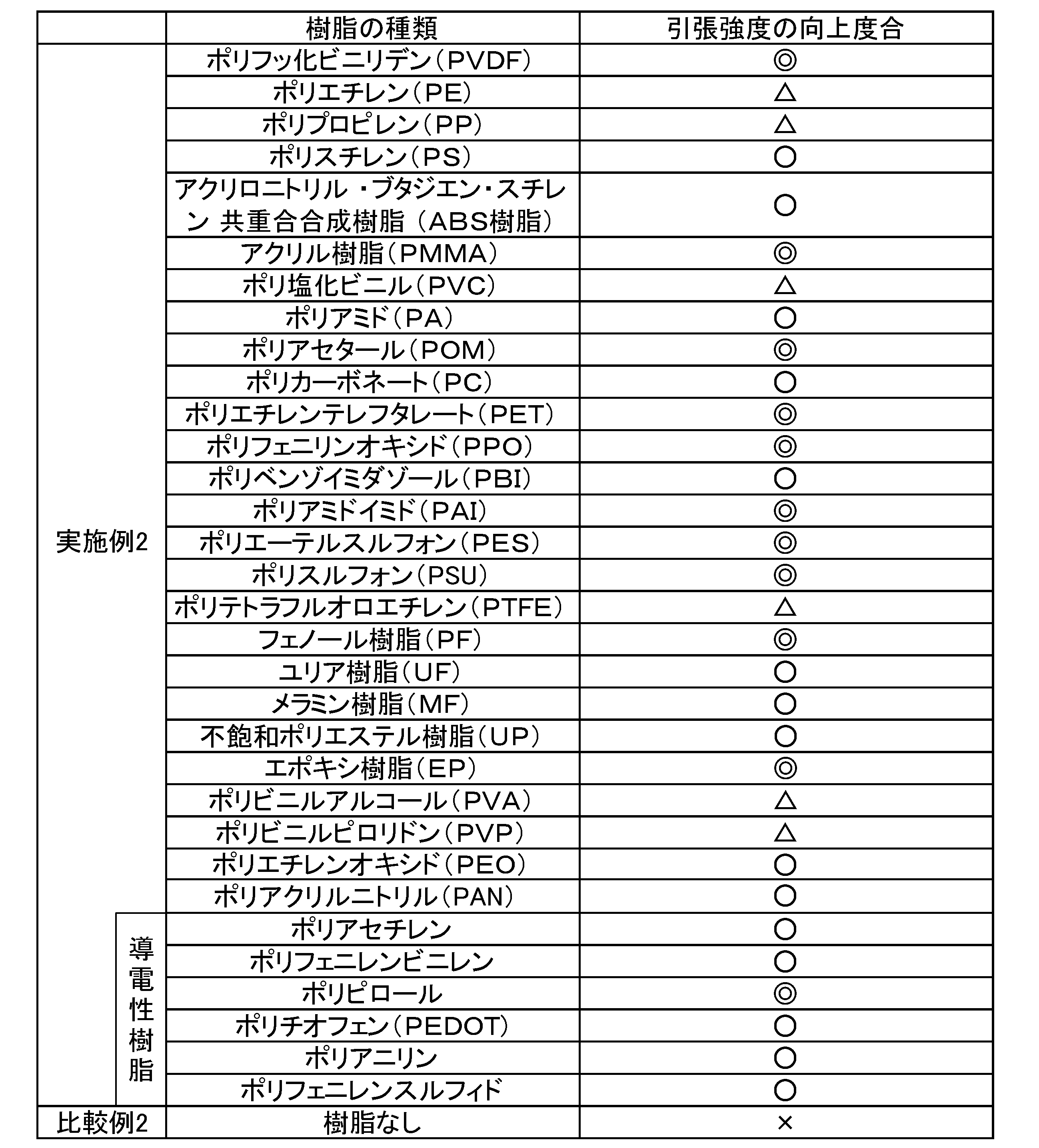
表2に示すように、実施例2の電気化学セル用集電体は引張強度が向上していることがわかる。電気化学セル用集電体は、上記の樹脂を用いて作製した樹脂組成物で骨格を覆うことで、強度を向上できることがわかる。
(実施例3)
電気化学セルは、製造時、コンマロールコータによって電気化学セル用集電体に電極合材が塗布される。このとき電気化学セル用集電体は、円柱状のロールに掛けられ引張力をかけられる。そこで、実施例3では、実際の電気化学セルの製造方法により近い下記の方法で電気化学セル用集電体の強度を評価した。
電気化学セルは、製造時、コンマロールコータによって電気化学セル用集電体に電極合材が塗布される。このとき電気化学セル用集電体は、円柱状のロールに掛けられ引張力をかけられる。そこで、実施例3では、実際の電気化学セルの製造方法により近い下記の方法で電気化学セル用集電体の強度を評価した。
厚さ1mm、幅300mm、長さ2mの電気化学セル用集電体を作製し、電気化学セル用集電体の長軸方向の両端を溶接により接着し、長さ約1mの無端の電気化学セル用集電体を作製した。
円柱形状をし、円柱の中心軸を軸として回転できる2つ金属製ロール(直径10cm)を1mの間隔をあけて配置した。無端状にした電気化学セル用集電体を2つの金属ロールに掛け、一方の金属ロールをモータで回転させることにより、電気化学セル用集電体を回転できるように設置した。
電気化学セル用集電体を10m/minの速度で500回、回転させた後の電気化学セル用集電体の質量の減少量を測定し、当該質量減少量を初期の電気化学セル用集電体の質量に対する割合(百分率)で表し、強度を評価した。
実施例3では、気孔率85%の発泡アルミを用い、アルミニウムで形成された骨格の質量に対して5wt%の割合で樹脂組成物としてのPVDFを含む電気化学セル用集電体と、気孔率90%の発泡銅を用い、銅で形成された骨格の質量に対して2wt%の割合で樹脂組成物としてのSBRを含む電気化学セル用集電体を作製し、上記の方法で強度を評価した。
発泡銅を用いた電気化学セル用集電体は以下の方法で作製した。まず、銅の微粉末(アルドリッチ社製、平均粒径10μm)200gを水溶性の界面活性剤(花王社製、製品名:エマール、品番20T)6gと水500mLとを混ぜてスラリーを作製した。
次に、ドクターブレード法により、作製したスラリーをペットフィルム(東レ社製、製品名:トレファン、品番2500T)上に薄く塗布してシート成型した。このとき、同時に、50℃に加熱して成型したシートに泡を形成しつつ、乾燥した。その後、500℃程度のアルゴン雰囲気下で焼結して気孔率90%、厚さ1mm、幅300mm、長さ2mの発泡銅を形成し、銅で形成された骨格を作製した。
次いで、電気化学セル用集電体を作製するためのスラリーを作製する。SBR:CMCが質量比で1:1になるように計量する。水にSBRを十分、分散させた後、CMCを溶かした水溶液をさらに投入して、SBR及びCMCの合計の質量濃度が10wt%の樹脂溶液を作製した。その後、骨格を樹脂溶液に3分浸漬し、110℃で90分間乾燥させて、骨格の質量に対して2wt%の割合でSBRを含む電気化学セル用集電体を作製した。SBR及びCMCの合計の質量濃度を変えることで、骨格の質量に対するSBRの含有量を変えることができる。
また、比較のために比較例3として、実施例3で用いた発泡アルミと発泡銅の強度を上記の方法で評価した。これらの結果を表3に示す。
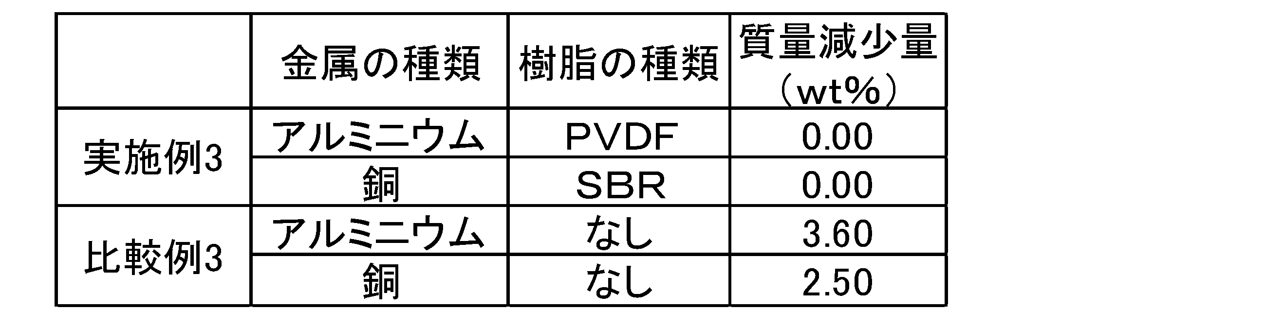
実施例3の電気化学セル用集電体は質量減少量が0であることから、電気化学セル用集電体が破損していないことがわかる。一方、比較例の電気化学セル用集電体は質量減少量が0でないことから、電気化学セル用集電体が欠け、電気化学セル用集電体の欠片が脱落して質量が減少したことがわかる。このように本発明の電気化学セル用集電体は、樹脂組成物4を含むこととで強度を向上でき、欠けを抑制できることが確認できた。
(実施例4)
実施例4として、本発明の電気化学セル用集電体を正極に用いたリチウムイオン二次電池を作製し、その特性を評価した。
実施例4として、本発明の電気化学セル用集電体を正極に用いたリチウムイオン二次電池を作製し、その特性を評価した。
まず、実施例1と同様の方法で気孔率94%、厚さ300μmの発泡アルミを作製し、発泡アルミを幅30mm、長さ25mmの大きさに切断してアルミニウムで形成された骨格を作製した。
次に、実施例1と同様の方法により、骨格の質量に対して0.1、1、5、10、50、100、200wt%のPVDFを含む電気化学セル用集電体を作製した。PVDFの含有割合は、溶媒への樹脂の投入量を調整することで変化させた。
次いで、活物質としてのLiCoO2(LCO)、バインダーとしてのPVDF、導電助剤としてのアセチレンブラック(AB)の質量比が98:1:1となるようにそれぞれ計量した。その後、計量したPVDFを溶媒N-メチル-2-ピロリドン(NMP)に添加し、20分攪拌した。さらにLCO及びABを添加して攪拌し、粘度6Pa・sに調整した正極スラリーを作製した。
続いて、各電気化学セル用集電体を正極スラリーに5分間浸した後、表面に付着している余分な正極スラリーをヘラで落とし、120℃で1時間乾燥させて、正極を作製した。
次いで、活物質として天然黒鉛、バインダーとしてSBR、導電助剤としてのAB、増粘剤としてCMCを質量比が97:1:1:1となるように計量した。計量後、水にCMCを溶解させ濃度1%の水溶液を作製し、当該水溶液と天然黒鉛とABとを自転公転ハイブリッドミキサー(株式会社シンキー製、モデル:ARE-310)に投入して10分撹拌した。さらに、SBRを分散させた溶液を投入して10分撹拌した。その後、適宜水を加えさらに攪拌し、粘度を800mPa・sに調整した負極スラリーを作製した。
次いで、厚さ10μmの銅箔を正極と同じ形状に切断して負極用の集電体を作製し、負極用の集電体の一表面に、コンマロールコータによって負極スラリーを塗工し、120℃で1時間乾燥させて厚さ300μmの負極合材層を集電体表面に形成し、負極を作製した。
最後に、正極と負極の間に無数の微細孔を有するポリエチレン製のセパレータを挟み、エチレンカーボネート(EC)とエチルメチルカーボネート(EMC)とジメチルカーボネート(DMC)とを体積比1:1:1の割合で混合した溶媒に1MのLiPF6を添加した電解液と共に、アルミラミネートパックに挿入し、真空パックをしてラミネートセル状の実施例4のリチウムイオン二次電池を作製した。
このようにして作製したリチウムイオン二次電池の放電容量と容量維持率を測定し、リチウムイオン二次電池の特性を評価した。
まずリチウムイオン二次電池の放電容量を測定した。放電容量は、1mA/cm2の定電流、4.2Vvs.Li/Li+の定電圧で充電電流値が0.1mA/cm2に低下するまで充電した後、カットオフ電圧を3.0Vvs.Li/Li+として、1C放電と、0.2C放電との2つの放電条件で測定した。
次にリチウムイオン二次電池の容量維持率を測定した。容量維持率(%)は、充放電を繰り返し行うサイクル試験の1サイクル目の放電容量を100としたときのサイクル試験後の放電容量である。容量維持率は、0.2C充電、0.2C放電を1サイクルとし、充放電を100サイクル繰り返してサイクル試験を行い、サイクル試験前後の放電容量を測定し、当該測定結果から算出した。容量維持率は、電気化学セルのサイクル特性を表す値であり、この値が大きいほどサイクル特性が良い、すなわち、耐久性がある。実施例4のリチウムイオン二次電池の放電レートを変化させた放電容量とサイクル試験後の容量維持率(%)とを表4に示す。
また、比較例4として、実施例4の電気化学セル用集電体に用いた発泡アルミを正極の集電体とした点のみ実施例4のリチウムイオン二次電池と異なるリチウムイオン二次電池を作製し、実施例4と同様に放電容量と容量維持率とを測定した。比較例4の放電容量と容量維持率との測定結果も表4に示す。表4中の放電容量の値は、比較例4の0.2C放電時の放電容量の値を100としたときの各実施例及び1C放電時の比較例の放電容量の値を表している。
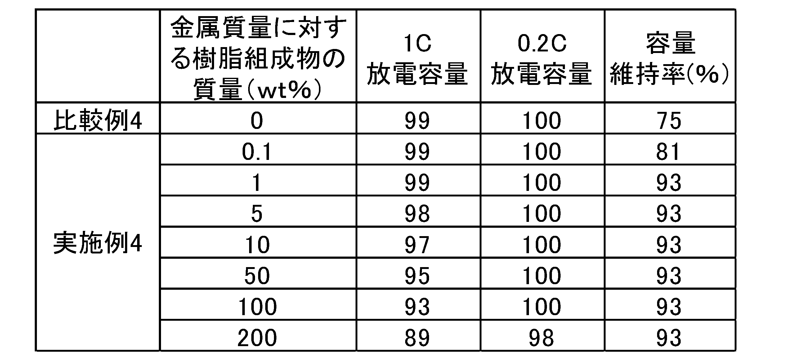
実施例4のリチウムイオン二次電池は、比較例4のリチウムイオン二次電池と比較して、それぞれ容量維持率が高く、サイクル特性が向上していることがわかる。これは、電気化学セル用集電体が、樹脂組成物を含むことで補強されて強度が向上し、欠けを抑制でき、リチウムイオン二次電池の充放電過程における収縮・膨張による電気化学セル用集電体の欠けや金属粒子5同士の結合が解かれて電気的なパスが切れてしまうことが抑制されたからであると考えられる。このように、本発明の電気化学セル用集電体は、強度が向上し、リチウムイオン二次電池の電極に用いたときに、リチウムイオン二次電池のサイクル特性を向上できる。
また、実施例4のリチウムイオン二次電池は、樹脂組成物の含有量が低いほど放電容量が大きいことがわかる。これは、樹脂組成物の含有量が増えるほど、電気化学セル用集電体の導電性が低下してリチウムイオン二次電池の内部抵抗の増加原因となり、また、担持できる活物質の量も減少するからであると考えられる。具体的には、骨格の質量に対する樹脂組成物の質量が0.1~200wt%であれば、放電容量の低下が小さく、骨格の質量に対する樹脂組成物の質量が0.1~100wt%であれば、より放電容量の低下が小さく、0.2C放電の場合は放電容量の低下が0であり、骨格の質量に対する樹脂組成物の質量が0.1~10wt%であれば、放電容量の低下が1C放電の場合にも極めて小さいことがわかる。電気化学セル用集電体は、骨格の質量に対して0.1~200wt%の樹脂組成物を含んでいることが望ましく、骨格の質量に対して0.1~100wt%の樹脂組成物を含んでいることがより望ましく、骨格の質量に対して0.1~10wt%の樹脂組成物を含んでいることがさらに望ましいことが確認できた。
(実施例5)
実施例5として、本発明の電気化学セル用集電体を電極に用いたEDLCを作製し、その特性を評価した。
実施例5として、本発明の電気化学セル用集電体を電極に用いたEDLCを作製し、その特性を評価した。
まず、実施例4と同様の方法により、実施例4の電気化学セル用集電体と同じサイズであり、気孔率が94%の発泡アルミを用い、アルミニウムで形成された骨格の質量に対して0.1、1、5、10、50、100、200wt%のPVDFを含む電気化学セル用集電体を作製した。
次いで、活物質としてのヤシガラ活性炭(クラレケミカル株式会社製、型番YP-50F)、バインダーとしてのPVDF、導電助剤としてのABの質量比が90:5:5となるようにそれぞれ計量した。その後、計量したPVDFを溶媒N-メチル-2-ピロリドン(NMP)に添加し、20分攪拌した。さらにヤシガラ活性炭及びABを添加して攪拌し、粘度6Pa・sに調整した電極スラリーを作製した。
続いて、各電気化学セル用集電体を電極スラリーに5分間浸した後、表面に付着している余分な電極スラリーをヘラで落とし、120℃で1時間乾燥させて、EDLC用電極を作製した。
最後に、2つのEDLC用電極の間に無数の微細孔を有するセルロース製のセパレータを挟み、溶媒であるプロピレンカーボーネート(PC)中に電解質であるテトラエチルアンモニウム4フッ化ホウ酸(N(C2H5)4BF4)が1モル含まれた電解液と共に、アルミラミネートパックに挿入し、真空パックをしてラミネートセル状の実施例5のEDLCを作製した。因みにこの時点では、正極・負極の区別はなく、キャパシタが完成し、プラス電圧を印加した方が正極となり、マイナス電圧を印加した方が負極となる。
このようにして作製したEDLCの放電容量と容量維持率を測定し、EDLCの特性を評価した。
放電容量は、2mA/cm2の定電流で充電し、正極と負極との電圧が2.4Vに到達した後、カットオフ電圧を1Vとして、100C放電と、10C放電との2つの放電条件で測定した。
容量維持率は、50C充電、50C放電を1サイクルとし、充放電を10000サイクル繰り返してサイクル試験を行い、サイクル試験前後の放電容量を測定し、当該測定結果から算出した。実施例5のEDLCの放電レートを変化させた放電容量とサイクル試験後の容量維持率(%)とを表5に示す。
また、比較例5として、実施例5の電気化学セル用集電体に用いた発泡アルミを各電極の集電体とした点のみ実施例5のEDLCと異なるEDLCを作製し、実施例5と同様に放電容量と容量維持率とを測定した。比較例5の放電容量と容量維持率との測定結果も表5に示す。表5中の放電容量の値は、比較例5の10C放電時の放電容量の値を100としたときの各実施例及び100C放電時の比較例の放電容量の値を表している。

実施例5のEDLCは、比較例5のEDLCと比較して、それぞれ容量維持率が高く、サイクル特性が向上していることがわかる。このように、本発明の電気化学セル用集電体は、強度が向上して欠けを抑制でき、PVDFによる被覆により、サイクル中の充放電に伴う熱膨張収縮によると考えられる発泡アルミからの活性炭の脱離もなくなるために、高い容量が維持できると考えられる。EDLCの電極に用いたときに、EDLCのサイクル特性を向上できる。
また、実施例5のEDLCは、樹脂組成物の含有量が低いほど放電容量が大きいことがわかる。これは、樹脂組成物の含有量が増えるほど、電気化学セル用集電体の導電性が低下してEDLCの内部抵抗の増加原因となり、また、担持できる活物質の量も減少するからであると考えられる。具体的には、骨格の質量に対する樹脂組成物の質量が0.1~200wt%であれば、放電容量の低下が小さく、骨格の質量に対する樹脂組成物の質量が0.1~100wt%であれば、より放電容量の低下が小さく、10C放電の場合は放電容量の低下が0か1であり、骨格の質量に対する樹脂組成物の質量が0.1~10wt%であれば、放電容量の低下が100C放電の場合にも極めて小さいことがわかる。電気化学セル用集電体は、骨格の質量に対して0.1~200wt%の樹脂組成物を含んでいることが望ましく、骨格の質量に対して0.1~100wt%の樹脂組成物を含んでいることがより望ましく、骨格の質量に対して0.1~10wt%の樹脂組成物を含んでいることがさらに望ましいことが確認できた。
(実施例6)
実施例6として、本発明の電気化学セル用集電体を正極及び負極に用いたリチウムイオンキャパシタを作製し、その特性を評価した。
実施例6として、本発明の電気化学セル用集電体を正極及び負極に用いたリチウムイオンキャパシタを作製し、その特性を評価した。
まず、実施例5と同様の方法により、実施例5の電気化学セル用集電体と同じサイズであり、骨格の質量に対して0.1、1、5、10、50、100、200wt%のPVDFを含む電気化学セル用集電体を用いてそれぞれリチウムイオンキャパシタ用電極を作製した。当該電極をリチウムイオンキャパシタの正極とした。
次に、実施例3と同様の方法で、気孔率70%、厚さ300μmの発泡銅を作製し、当該発泡銅を正極と同じ形状に切断して銅で形成された骨格を作製した。
次いで、リチウムイオンキャパシタの負極用の電気化学セル用集電体を作製するためのスラリーを作製する。SBR:CMCが質量比で1:1になるように計量する。水にSBRを十分、分散させた後、CMCを溶かした水溶液をさらに投入してSBR及びCMCの合計の質量濃度が2wt%、粘度が50mPa・sの樹脂溶液を作製した。その後、切断した骨格を樹脂溶液に3分浸漬した。浸漬した骨格を110℃で90分間乾燥させて、骨格の質量に対して0.1wt%の割合でSBRを含む電気化学セル用集電体を作製した。
続いて、活物質としての天然黒鉛、導電助剤としてのAB、バインダーとしてのSBR、増粘剤としてのCMCの質量比が97:1:1:1となるように計量した。計量後、水にCMCを溶解させ濃度1%の水溶液を作製し、当該水溶液と天然黒鉛とABとを自転公転ハイブリッドミキサーに投入して10分撹拌した。さらに、SBRを分散させた溶液を投入して10分撹拌した。その後、適宜水を加えさらに攪拌し、粘度500mPa・sに調整した負極スラリーを作製した。
次いで、電気化学セル用集電体を上記の負極スラリーに5分間浸した後、表面に付着している余分な負極スラリーをヘラで落とし、110℃で5時間乾燥させてリチウムイオンキャパシタ用の負極を作製した。
最後に、正極と負極の間に無数の微細孔を有するセルロース製のセパレータを挟み、溶媒であるエチレンカーボーネート(EC):ジエチルカーボネート(DEC):エチルメチルカーボネート(EMC)=3:3:4中に電解質である4フッ化ホウ酸リチウム(LiBF4)が1モル含まれた電解液と共に、負極黒鉛のプレドープ用の金属Li箔をアルミラミネートパックに挿入し、真空パックをしてラミネートセル状の実施例6のリチウムイオンキャパシタを作製した。
このようにして作製したリチウムイオンキャパシタの放電容量と容量維持率を測定し、リチウムイオンキャパシタの特性を評価した。
放電容量は、2mA/cm2の定電流、正極-負極間が4.0Vに到達した後、放電を開始し、カットオフ電圧を2Vとして、50C放電と、10C放電との2つの放電条件で測定した。
容量維持率は、50C充電、50C放電を1サイクルとし、充放電を10000サイクル繰り返してサイクル試験を行い、サイクル試験前後の放電容量を測定し、当該測定結果から算出した。実施例6のリチウムイオンキャパシタの放電レートを変化させた放電容量とサイクル試験後の容量維持率(%)とを表6に示す。
また、比較例6として、実施例6の電気化学セル用集電体に用いた発泡アルミを正極の集電体とし、発泡銅を負極の集電体とした点のみ実施例6のリチウムイオンキャパシタと異なるリチウムイオンキャパシタを作製し、実施例6と同様に放電容量と容量維持率とを測定した。比較例6の放電容量と容量維持率との測定結果も表6に示す。表6中の放電容量の値は、比較例6の10C放電時の放電容量の値を100としたときの各実施例及び50C放電時の比較例の放電容量の値を表している。
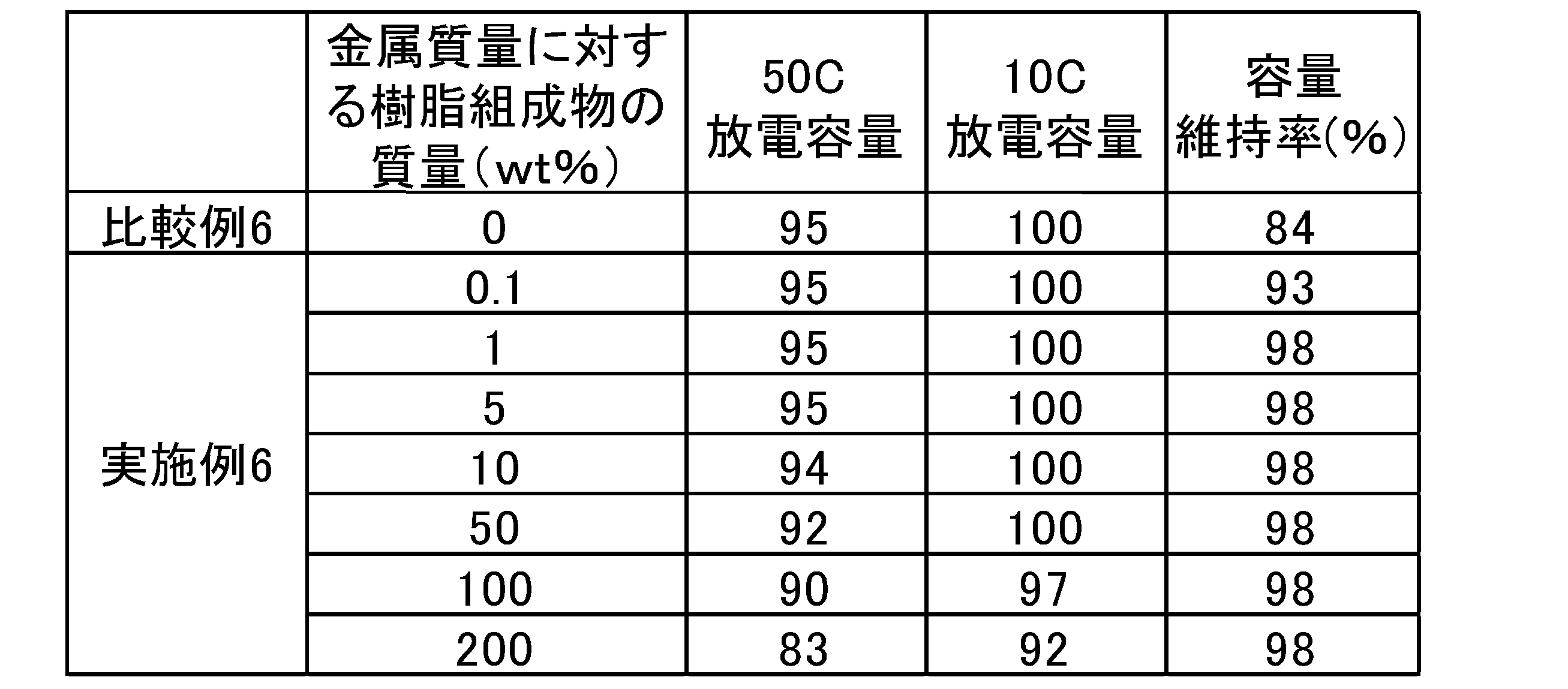
実施例6のリチウムイオンキャパシタは、比較例6のリチウムイオンキャパシタと比較して、それぞれ容量維持率が高く、サイクル特性が向上していることがわかる。このように、本発明の電気化学セル用集電体は、強度が向上して欠けを抑制でき、リチウムイオンキャパシタの電極に用いたときに、リチウムイオンキャパシタのサイクル特性を向上できる。
また、実施例6のリチウムイオンキャパシタは、樹脂組成物の含有量が低いほど放電容量が大きいことがわかる。これは、樹脂組成物の含有量が増えるほど、電気化学セル用集電体の導電性が低下してリチウムイオンキャパシタの内部抵抗の増加原因となり、また、担持できる活物質の量も減少するからであると考えられる。具体的には、骨格の質量に対する樹脂組成物の質量が0.1~200wt%であれば、放電容量の低下が小さく、骨格の質量に対する樹脂組成物の質量が0.1~100wt%であれば、より放電容量の低下が小さく、10C放電の場合は放電容量の低下が0か3であり、骨格の質量に対する樹脂組成物の質量が0.1~10wt%であれば、放電容量の低下が50C放電の場合にも極めて小さいことがわかる。電気化学セル用集電体は、骨格の質量に対して0.1~200wt%の樹脂組成物を含んでいることが望ましく、骨格の質量に対して0.1~100wt%の樹脂組成物を含んでいることがより望ましく、骨格の質量に対して0.1~10wt%の樹脂組成物を含んでいることがさらに望ましいことが確認できた。
(実施例7)
実施例7では、ビーズを用いて作製した骨格を樹脂組成物で覆って補強した電気化学セル用集電体を電極に用いたEDLCを作製し、その特性を評価した。
実施例7では、ビーズを用いて作製した骨格を樹脂組成物で覆って補強した電気化学セル用集電体を電極に用いたEDLCを作製し、その特性を評価した。
まず、ビーズとアルミニウム粉を体積比で80:20の割合で計量し、プラスチック容器に投入した。具体的には、球形状の平均粒径100μmのポリエチレン製ビーズを100mLの容器で8回すくって3Lのプラスチック容器に投入し、平均粒径10μmのアルミニウム粉(アルドリッチ社製)を100mLの容器で2回すくって当該プラスチック容器に投入した。その後、ビーズとアルミニウム粉が投入されたプラスチック容器内にバインダーとしてポリビニルアルコール(PVA)粉末を35g投入した。
次に、プラスチック容器内に直径5mmのアルミナ製のボールを3kg投入した後、プラスチック容器に蓋をして24時間、60回転/分の速度でプラスチック容器を回転させ、ボールミル混合を実施した。その後、ボールミル混合で得られた混合粉を目開き3mmメッシュの篩にかけ、混合粉からアルミナボールを取り出した。
続いて、アルミナボールを取り出した混合粉を縦3cm、横3cm、深さ1cmの金型に1g投入し、200kg/cm2の荷重で混合粉をプレスして圧粉体を作製した。
次いで、雰囲気制御可能なベルト炉内に圧粉体を配置し、大気雰囲気中で炉内を350℃まで5時間かけて昇温し、炉内の温度を350℃に10時間保持して圧粉体を加熱することで、圧粉体中のビーズのポリエチレンを蒸発させてビーズを除去する。
続いて、ベルト炉内をアルゴン雰囲気にし、炉内を655℃まで3時間かけて昇温し、炉内の温度を655℃に1時間保持し、3時間かけて100℃まで炉内の温度を下げて圧粉体を焼結することでアルミニウム焼結体を作製した。作製したアルミニウム焼結体は、厚さ0.4mm、気孔率70%であった。当該アルミニウム焼結体を幅10mm、長さ25mmにカットし、アルミニウムで形成された骨格を用意した。
最後に、用意した骨格をNMPにPVDFを溶解した樹脂溶液に浸漬した後、樹脂溶液から取り出して余分な樹脂溶液をふき取り、大気雰囲気中において120℃で3時間乾燥させて実施例7の電気化学セル用集電体を作製した。実施例7の電気化学セル用集電体は骨格の質量に対して1.6wt%の割合でPVDFを含んでいた。
実施例7の電気化学セル用集電体を正極及び負極の両電極の集電体に用いて、実施例5と同様の方法、条件で、実施例7のEDLCを作製した。実施例7のEDLCの放電容量と容量維持率(%)を、実施例5と同様の方法、条件で測定し、実施例7のEDLCの特性を評価した。
また、比較のために比較例7として、実施例7の電気化学セル用集電体に変えて、実施例7の電気化学セル用集電体の作製に用いた骨格(アルミニウム焼結体)を正極及び負極の両電極の集電体として用いた点のみ実施例7のEDLCと異なるEDLCを作製し、実施例7と同様に放電容量と容量維持率とを測定した。実施例7及び比較例7の放電容量と容量維持率の測定結果を表7に示す。表7中の放電容量の値は、比較例7の10C放電時の放電容量の値を100として規格化した値を表している。

実施例7のEDLCは、比較例7のEDLCと比較して、容量維持率が高く、サイクル特性が向上していることがわかる。このように、実施例7の電気化学セル用集電体は、強度が向上したことで欠けを抑制でき、PVDFによる被覆により、サイクル中の充放電に伴う熱膨張収縮によると考えられる電気化学セル用集電体からの活性炭の脱離も抑制できるために、高い容量が維持できると考えられる。
このように、ビーズを用いて作製したアルミニウム焼結体で骨格が形成された場合も、電気化学セル用集電体は、樹脂組成物で骨格を補強することで、電気化学セル用集電体の強度を向上でき、EDLCの電極に用いたときに、EDLCのサイクル特性を向上できる。
1 電気化学セル用集電体
2 骨格
3 中抜き細孔
4 樹脂組成物
5 金属粒子
6 空隙
2 骨格
3 中抜き細孔
4 樹脂組成物
5 金属粒子
6 空隙
Claims (11)
- 複数の金属粒子が結合した焼結体で形成され、3次元網目構造をした骨格と、
前記骨格によって区切られた領域に存在する中抜き細孔と、
前記骨格内部の前記金属粒子同士の間に形成された空隙とを有し、
少なくとも前記空隙に樹脂組成物を含み、
前記中抜き細孔同士は、液体や気体が流通するように内部空間が互いに連通している
ことを特徴とする電気化学セル用集電体。 - 気孔率が70%以上である
ことを特徴とする請求項1に記載の電気化学セル用集電体。 - 前記中抜き細孔は、球形状をしている
ことを特徴とする請求項1又は2に記載の電気化学セル用集電体。 - 前記樹脂組成物を含む前記骨格にバインダーを介して活物質を結着させて電気化学セル用電極として用い、
前記樹脂組成物が前記バインダーと同じ樹脂で形成されている
ことを特徴とする請求項1~3のいずれか1項に記載の電気化学セル用集電体。 - 前記中抜き細孔の内面が前記樹脂組成物で覆われている
ことを特徴とする請求項1~4のいずれか1項に記載の電気化学セル用集電体。 - 前記樹脂組成物が、前記骨格の質量の0.1~200wt%含まれている
ことを特徴とする請求項1~5のいずれか1項に記載の電気化学セル用集電体。 - 前記中抜き細孔の内面を覆う前記樹脂組成物の厚さが0.05~100μmである
ことを特徴とする請求項5に記載の電気化学セル用集電体。 - 前記樹脂組成物が、ポリフッ化ビニリデン、スチレン・ブタジエン・ラバー、ポリアミドイミド、ポリテトラフルオロエチレンから選ばれる1つ以上を含む
ことを特徴する請求項1~7のいずれか1項に記載の電気化学セル用集電体。 - 請求項1~8のいずれか1項に記載の電気化学セル用集電体を用いた電極を備える
ことを特徴とするリチウムイオン二次電池。 - 請求項1~8のいずれか1項に記載の電気化学セル用集電体を用いた電極を備える
ことを特徴とする電気二重層キャパシタ。 - 請求項1~8のいずれか1項に記載の電気化学セル用集電体を用いた電極を備える
ことを特徴とするリチウムイオンキャパシタ。
Applications Claiming Priority (4)
| Application Number | Priority Date | Filing Date | Title |
|---|---|---|---|
| JP2015066143 | 2015-03-27 | ||
| JP2015-066143 | 2015-03-27 | ||
| JP2015200076A JP2016178077A (ja) | 2014-10-16 | 2015-10-08 | 電気化学セル用集電体、リチウムイオン二次電池、電気二重層キャパシタ及びリチウムイオンキャパシタ |
| JP2015-200076 | 2015-10-08 |
Publications (1)
| Publication Number | Publication Date |
|---|---|
| WO2016158662A1 true WO2016158662A1 (ja) | 2016-10-06 |
Family
ID=57004247
Family Applications (1)
| Application Number | Title | Priority Date | Filing Date |
|---|---|---|---|
| PCT/JP2016/059367 Ceased WO2016158662A1 (ja) | 2015-03-27 | 2016-03-24 | 電気化学セル用集電体、リチウムイオン二次電池、電気二重層キャパシタ及びリチウムイオンキャパシタ |
Country Status (1)
| Country | Link |
|---|---|
| WO (1) | WO2016158662A1 (ja) |
Citations (7)
| Publication number | Priority date | Publication date | Assignee | Title |
|---|---|---|---|---|
| JPH0959596A (ja) * | 1995-08-22 | 1997-03-04 | Akebono Brake Res & Dev Center Ltd | 三次元網目構造の金属を骨格とする摩擦材およびその製造方法 |
| JP2002089561A (ja) * | 2000-09-14 | 2002-03-27 | Oiles Ind Co Ltd | 多孔質静圧気体軸受の製造方法 |
| JP2006313648A (ja) * | 2005-05-06 | 2006-11-16 | Hitachi Metals Ltd | 多孔質放熱部材 |
| JP2006322068A (ja) * | 2005-04-21 | 2006-11-30 | Nagamine Seisakusho:Kk | 多孔質部材およびその製造方法 |
| JP2014065955A (ja) * | 2012-09-27 | 2014-04-17 | Sumitomo Electric Ind Ltd | 金属多孔体及びその製造方法 |
| JP2014091151A (ja) * | 2012-11-05 | 2014-05-19 | Mitsubishi Materials Corp | 多孔質複合金属体の製造方法及び製造装置 |
| JP2014194074A (ja) * | 2013-03-01 | 2014-10-09 | Mitsubishi Materials Corp | 多孔質アルミニウム焼結体 |
-
2016
- 2016-03-24 WO PCT/JP2016/059367 patent/WO2016158662A1/ja not_active Ceased
Patent Citations (7)
| Publication number | Priority date | Publication date | Assignee | Title |
|---|---|---|---|---|
| JPH0959596A (ja) * | 1995-08-22 | 1997-03-04 | Akebono Brake Res & Dev Center Ltd | 三次元網目構造の金属を骨格とする摩擦材およびその製造方法 |
| JP2002089561A (ja) * | 2000-09-14 | 2002-03-27 | Oiles Ind Co Ltd | 多孔質静圧気体軸受の製造方法 |
| JP2006322068A (ja) * | 2005-04-21 | 2006-11-30 | Nagamine Seisakusho:Kk | 多孔質部材およびその製造方法 |
| JP2006313648A (ja) * | 2005-05-06 | 2006-11-16 | Hitachi Metals Ltd | 多孔質放熱部材 |
| JP2014065955A (ja) * | 2012-09-27 | 2014-04-17 | Sumitomo Electric Ind Ltd | 金属多孔体及びその製造方法 |
| JP2014091151A (ja) * | 2012-11-05 | 2014-05-19 | Mitsubishi Materials Corp | 多孔質複合金属体の製造方法及び製造装置 |
| JP2014194074A (ja) * | 2013-03-01 | 2014-10-09 | Mitsubishi Materials Corp | 多孔質アルミニウム焼結体 |
Similar Documents
| Publication | Publication Date | Title |
|---|---|---|
| JP6871342B2 (ja) | 電極、電極製造方法、並びに二次電池及びその製造方法 | |
| US9077041B2 (en) | Electrode structure for electrochemical cell | |
| JP3568052B2 (ja) | 金属多孔体、その製造方法及びそれを用いた電池用極板 | |
| KR20140014169A (ko) | 에너지 저장 장치용 다공성 구조체 | |
| JP5837437B2 (ja) | 非水系二次電池用セパレータおよび非水系二次電池 | |
| JP2004259636A (ja) | 非水電解質二次電池 | |
| CN104103791A (zh) | 一种电池复合隔膜及其制备方法 | |
| JP2016058257A (ja) | リチウムイオン二次電池用正極及びリチウムイオン二次電池 | |
| KR20140039305A (ko) | 내열 절연층을 갖는 세퍼레이터 | |
| TWI483446B (zh) | A battery collector, a battery positive electrode, a battery negative electrode, a battery, and a manufacturing method | |
| CN113169313A (zh) | 包括弹性可压缩功能层的电池及其制造工艺 | |
| WO2016158663A1 (ja) | 金属多孔質体 | |
| JP2016176135A (ja) | 金属多孔質体 | |
| JP2007123237A (ja) | 非水電解質電池、非水電解質電池用電極、及びこの非水電解質電池用電極の製造方法 | |
| CN117154182B (zh) | 电解质成分渐变的固态硅-硫电池及其制备方法与应用 | |
| JP2016178077A (ja) | 電気化学セル用集電体、リチウムイオン二次電池、電気二重層キャパシタ及びリチウムイオンキャパシタ | |
| WO2013061789A1 (ja) | キャパシタ | |
| EP3367486B1 (en) | Aluminum nonwoven fiber member for collector of power storage device, method for manufacturing same, electrode in which aforementioned aluminum nonwoven fiber member is used, and method for manufacturing same | |
| JP6779859B2 (ja) | 非水系二次電池用負極及び該負極を用いた非水系二次電池 | |
| WO2016158662A1 (ja) | 電気化学セル用集電体、リチウムイオン二次電池、電気二重層キャパシタ及びリチウムイオンキャパシタ | |
| JP5951982B2 (ja) | 非水系二次電池用セパレータおよび非水系二次電池 | |
| JP7365048B2 (ja) | 二次電池の正極の製造方法、および、二次電池 | |
| JP6103521B2 (ja) | 非水電解液二次電池およびその製造方法 | |
| KR102954221B1 (ko) | 다양한 크기를 갖는 기공 구조를 포함하는 다공성 구조체, 이의 제조방법 및 이를 이용한 이차전지용 전극 | |
| JP2004311417A (ja) | 電極およびそれを用いた電気化学セル |
Legal Events
| Date | Code | Title | Description |
|---|---|---|---|
| 121 | Ep: the epo has been informed by wipo that ep was designated in this application |
Ref document number: 16772543 Country of ref document: EP Kind code of ref document: A1 |
|
| NENP | Non-entry into the national phase |
Ref country code: DE |
|
| 122 | Ep: pct application non-entry in european phase |
Ref document number: 16772543 Country of ref document: EP Kind code of ref document: A1 |