WO2016158504A1 - 注出口栓及び包装容器 - Google Patents
注出口栓及び包装容器 Download PDFInfo
- Publication number
- WO2016158504A1 WO2016158504A1 PCT/JP2016/058737 JP2016058737W WO2016158504A1 WO 2016158504 A1 WO2016158504 A1 WO 2016158504A1 JP 2016058737 W JP2016058737 W JP 2016058737W WO 2016158504 A1 WO2016158504 A1 WO 2016158504A1
- Authority
- WO
- WIPO (PCT)
- Prior art keywords
- spout
- sealing film
- packaging container
- tab
- bridge portion
- Prior art date
- Legal status (The legal status is an assumption and is not a legal conclusion. Google has not performed a legal analysis and makes no representation as to the accuracy of the status listed.)
- Ceased
Links
Images



Definitions
- the present invention relates to a spout stopper and a packaging container.
- ⁇ Packaging containers that contain fluid foods such as fermented milk drinks, milk, mineral water, tea, juice, soup, alcohols are known.
- a spout plug having a spout sealed with a breakable sealing film (emblem), a cap covering the spout, and an opening means built in the spout is formed at the spout of the packaging container.
- Various types of spout stoppers have been proposed.
- An object of the present invention is to provide a spout stopper and a packaging container that can be easily opened.
- the spout stopper is a spout provided at a spout of a packaging container and a sealing film for sealing the spout, the sealing film being connected to the spout via a thin-walled portion. And two foot portions provided above the sealing film and fixed to the sealing film, and a bridge portion connecting the two foot portions, for pulling the sealing film upward It has a tension member and a tab provided in the lower part of the bridge part of the tension member.
- the tab may be provided at the center of the bridge portion.
- the tab may be provided at a position shifted from the center of the bridge portion.
- a packaging container is a packaging container body, a spout provided at a spout of the packaging container body, and a sealing film that seals the spout, and is attached to the spout via a thin-walled portion.
- a sealing film connected to the sealing film; and two foot portions provided above the sealing film and fixed to the sealing film; and a bridge portion connecting the two foot portions, the sealing film
- a spout having a pulling member for pulling upward, a tab provided at a lower portion of the bridge portion of the pulling member, and a cap covering the spout of the spout plug.
- the spout provided at the spout of the packaging container, the sealing film for sealing the spout, the sealing film connected to the spout via the thin wall portion, and the sealing A tension member provided above the stop film and having two feet fixed to the sealing film and a bridge portion connecting the two feet, and for pulling the sealing film upward; Since it has the tab provided in the lower part of the bridge
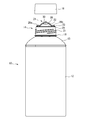
- FIG. 1 is a perspective view showing a packaging container according to this embodiment
- FIG. 2 is a side view showing the packaging container according to this embodiment
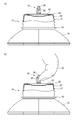
- FIG. 3 shows details of the spout stopper of the packaging container according to this embodiment and the opening method.
- the packaging container 10 is provided with a spout stopper 14 at the center of the dome-shaped top portion 13 of the packaging container body 12.
- the spout plug 14 is covered with a cap 16 at the time of transportation or storage.
- a cylindrical spout 20 is provided at a spout 18 of the packaging container body 12.
- a male screw 21 is formed on the outer peripheral surface of the spout 20.
- a female screw (not shown) is formed on the inner peripheral surface of the cap 16. The cap 16 is attached to the spout 20 of the spout stopper 14 by rotating the cap 16 on the spout 20 of the spout stopper 14. When removing the cap 16 from the spout 20 of the spout plug 14, the cap 16 is rotated in the reverse direction.
- the spout 20 of the spout stopper 14 is provided with a sealing film (emblem) 22 for sealing the spout 20 as shown in FIG.
- the sealing film (emblem) 22 is connected to the upper portion of the cylindrical spout 20 through the thin portion 23. When the sealing film (emblem) 22 is pulled upward, the thin portion 23 is broken and the sealing film (emblem) 22 can be detached from the spout 20.
- the spout 20 is made of, for example, LDPE (Low Density Polyethylene)
- the cap 16 is made of, for example, HDPE (High Density Polyethylene)
- the sealing film (emblem) 22 is made of, for example,
- the thin-walled portion 23 is formed of, for example, LDPE.
- the diameter of the spout 20 of the spout stopper 14 is, for example, 30 to 40 mm, and the wall thickness is, for example, 0.5 to 1.5 mm.
- the film thickness of the sealing film (emblem) 22 is, for example, 0.5 to 1.5 mm, and the thin portion 23 is, for example, 0.1 to 0.5 mm.
- the sealing film (emblem) 22 is provided with a tension member 24 for pulling the sealing film (emblem) 22 upward.
- the tension member 24 includes two foot portions 26 a and 26 b fixed to the peripheral portion of the sealing film (emblem) 22 and an arcuate bridge portion 28 that connects the two foot portions 26 a and 26 b.
- a tab 30 protruding from the center lower portion of the bridge portion 28 of the tension member 24 is provided. As shown in FIGS. 1 and 2, the tab 30 protrudes in the center of the arcuate bridge portion 28 and has a symmetrical shape with respect to the center of the bridge portion 28. As shown in FIG. 3A, the cross section of the tab 30 becomes thinner as it goes downward from the blister portion 28.
- the bridge portion 28 is formed by, for example, LDPE
- the tab 30 is formed by, for example, LDPE.
- the cross section of the bridge portion 28 of the tension member 24 is, for example, a square shape of 3.0 to 5.0 mm.
- the bridge portion 28 is an arc having a diameter of 20 to 30 mm, for example, and the central angle thereof is, for example, 150 to 180 degrees.
- the width of the tab 30 is, for example, 10 to 18 mm, and the height thereof is, for example, 2.0 to 5.0 mm.
- the tab 30 is continuous with the bridge portion 28, and the width of the upper portion thereof is, for example, 2.5 to 5.0 mm, and gradually becomes thinner.
- the operator places the finger 32 on the bridge portion 28 of the tension member 24 as shown in FIG.
- the bridge portion 28 is twisted in one direction by the tab 30.
- the twisting force is transmitted to the sealing film (emblem) 22 via the feet 26a and 26b, and is uneven with respect to the periphery of the sealing film (emblem) 22. Power is added.
- the bridge portion 28 is sealed via the feet 28 a and 28 b.
- a uniform force is applied to the periphery of the stop film (emblem) 22.
- the force is dispersed throughout the thin portion 23 around the periphery of the sealing film (emblem) 22, and a strong force is required to destroy the thin portion 23.
- FIG. 4 is a perspective view showing the packaging container according to the present embodiment
- FIG. 5 is a side view showing the packaging container according to the present embodiment.
- the same components as those in the first embodiment described above are denoted by the same reference numerals, and description thereof is omitted or simplified.
- the packaging container 10 is provided with a spout stopper 14 at the center of the dome-shaped top portion 13 of the packaging container body 12.
- the spout plug 14 is covered with a cap 16 at the time of transportation or storage.
- a cylindrical spout 20 is provided at a spout 18 of the packaging container body 12.
- a male screw 21 is formed on the outer peripheral surface of the spout 20.
- a female screw (not shown) is formed on the inner peripheral surface of the cap 16.
- the spout 20 of the spout plug 14 is provided with a sealing film (emblem) 22 for sealing the spout 20.
- the sealing film (emblem) 22 is connected to the upper portion of the cylindrical spout 20 through the thin portion 23.
- the sealing film (emblem) 22 is provided with a tension member 24 for pulling the sealing film (emblem) 22 upward.
- the tension member 24 includes two foot portions 26 a and 26 b fixed to the peripheral portion of the sealing film (emblem) 22 and an arcuate bridge portion 28 that connects the two foot portions 26 a and 26 b.
- a tab 34 is provided that protrudes to the lower part of the position shifted in one direction from the center of the bridge portion 28 of the tension member 24. As shown in FIGS. 1 and 2, the tab 34 protrudes at a position shifted in one direction from the center of the arcuate bridge portion 28. As in the first embodiment, the cross section of the tab 34 becomes thinner as it goes downward from the blister portion 28.
- the width of the tab 34 is, for example, 10 to 13 mm, and the height thereof is, for example, 2.0 to 5.0 mm.
- the tab 34 is continuous with the bridge portion 28, and the width of the upper portion thereof is, for example, 2.5 to 5.0 mm, and gradually becomes thinner.
- the tab 34 is provided at the lower part of the tension member 24 at a position shifted in one direction from the center of the bridge portion 28. Therefore, the tab 34 is not provided and the tab 34 is not provided in the other direction. A large space is formed at the bottom. For this reason, the operator can easily put a finger in the lower part of the bridge portion 28.
- the tab is provided at the center lower part of the bridge part or at the lower part of the position shifted in one direction from the center, but it is not limited to the tab forming position, its shape, or the above embodiment.
- a part of the periphery of the sealing film for example, the bridge part is twisted by a tab. You may make it make the thin part of the part to which a strong force is added thinner. Thereby, a sealing film can be made to detach
Landscapes
- Containers Opened By Tearing Frangible Portions (AREA)
- Closures For Containers (AREA)
Abstract
容易に開封することができる注出口栓及び包装容器を提供する。包装容器本体と、包装容器本体の注出口に設けられたスパウトと、スパウトを封止する封止フィルムであって、薄肉部を介してスパウトに接続された封止フィルムと、封止フィルムの上方に設けられ、封止フィルムに固定された2つの足部と、2つの足部を繋ぐブリッジ部とを有し、封止フィルムを上方に引っ張るための引張部材と、引張部材のブリッジ部の下部に設けられたタブとを有する注出口栓と、注出口栓のスパウトを覆うキャップとを有する包装容器である。
Description
本発明は、注出口栓及び包装容器に関する。
発酵乳飲料、牛乳、ミネラルウォーター、茶、ジュース、スープ、アルコール類等の流動性食品を収容する包装容器が知られている。包装容器の注出口には、破断可能な封止フィルム(エンブレム)で封止されたスパウトと、スパウトを覆うキャップと、スパウトに内蔵された開封手段とを有する注出口栓が形成される。そのような注出口栓として、様々なタイプのものが提案されている。
本発明の目的は、容易に開封することができる注出口栓及び包装容器を提供することにある。
本発明の一態様による注出口栓は、包装容器の注出口に設けられたスパウトと、前記スパウトを封止する封止フィルムであって、薄肉部を介して前記スパウトに接続された封止フィルムと、前記封止フィルムの上方に設けられ、前記封止フィルムに固定された2つの足部と、前記2つの足部を繋ぐブリッジ部とを有し、前記封止フィルムを上方に引っ張るための引張部材と、前記引張部材の前記ブリッジ部の下部に設けられたタブとを有することを特徴とする。
上述した注出口栓において、前記タブは前記ブリッジ部の中央に設けてもよい。
上述した注出口栓において、前記タブは前記ブリッジ部の中央からずれた位置に設けてもよい。
本発明の一態様による包装容器は、包装容器本体と、前記包装容器本体の注出口に設けられたスパウトと、前記スパウトを封止する封止フィルムであって、薄肉部を介して前記スパウトに接続された封止フィルムと、前記封止フィルムの上方に設けられ、前記封止フィルムに固定された2つの足部と、前記2つの足部を繋ぐブリッジ部とを有し、前記封止フィルムを上方に引っ張るための引張部材と、前記引張部材の前記ブリッジ部の下部に設けられたタブとを有する注出口栓と、前記注出口栓の前記スパウトを覆うキャップとを有することを特徴とする。
以上の通り、本発明によれば、包装容器の注出口に設けられたスパウトと、スパウトを封止する封止フィルムであって、薄肉部を介してスパウトに接続された封止フィルムと、封止フィルムの上方に設けられ、封止フィルムに固定された2つの足部と、2つの足部を繋ぐブリッジ部とを有し、封止フィルムを上方に引っ張るための引張部材と、引張部材のブリッジ部の下部に設けられたタブとを有するので、注出口栓を容易に開封することができる。
[第1実施形態]
本発明の第1実施形態による包装容器について図1乃至図3を用いて説明する。図1は本実施形態による包装容器を示す斜視図であり、図2は本実施形態による包装容器を示す側面図であり、図3は本実施形態による包装容器の注出口栓の詳細及び開封方法を示す図である。
本発明の第1実施形態による包装容器について図1乃至図3を用いて説明する。図1は本実施形態による包装容器を示す斜視図であり、図2は本実施形態による包装容器を示す側面図であり、図3は本実施形態による包装容器の注出口栓の詳細及び開封方法を示す図である。
本実施形態による包装容器10は、包装容器本体12のドーム状頂部13の中央に注出口栓14が設けられている。注出口栓14は、運搬時、保管時等には、キャップ16が被せられている。
注出口栓14として、包装容器本体12の注出口18に筒型のスパウト20が設けられている。スパウト20の外周面には雄ねじ21が形成されている。キャップ16の内周面には雌ねじ(図示せず)が形成されている。キャップ16を注出口栓14のスパウト20に被せて回転させることにより、注出口栓14のスパウト20にキャップ16を装着する。キャップ16を注出口栓14のスパウト20から取り外すときは、キャップ16を逆方向に回転させる。
注出口栓14のスパウト20には、図3(a)に示すように、スパウト20を封止するための封止フィルム(エンブレム)22が設けられている。封止フィルム(エンブレム)22は、薄肉部23を介して筒型のスパウト20の上部に接続されている。封止フィルム(エンブレム)22を上方に引っ張ると、薄肉部23が破壊されて封止フィルム(エンブレム)22をスパウト20から離脱させることができる。
スパウト20は、例えば、LDPE(Low Density Polyethylene:低密度ポリエチレン)により形成され、キャップ16は、例えば、HDPE(High Density Polyethylene:高密度ポリエチレン)により形成され、封止フィルム(エンブレム)22は、例えば、LDPEにより形成され、薄肉部23は、例えば、LDPEにより形成されている。
注出口栓14のスパウト20の直径は、例えば、30~40mmであり、肉厚は、例えば、0.5~1.5mmである。封止フィルム(エンブレム)22の膜厚は、例えば、0.5~1.5mmであり、薄肉部23は、例えば、0.1~0.5mmである。
封止フィルム(エンブレム)22には、封止フィルム(エンブレム)22を上方に引っ張るために引張部材24が設けられている。引張部材24は、封止フィルム(エンブレム)22の周縁部に固定された2つの足部26a、26bと、2つの足部26a、26bを繋ぐ円弧状のブリッジ部28とにより構成されている。
本実施形態では、引張部材24のブリッジ部28の中央下部に突出したタブ30が設けられている。タブ30は、図1、図2に示すように、円弧状のブリッジ部28の中央に突出し、ブリッジ部28の中央に対して左右対称な形状をしている。タブ30の断面は、図3(a)に示すように、ブリッ部28から下方になるにしたがい薄くなっている。
ブリッジ部28は、例えば、LDPEにより形成され、タブ30は、例えば、LDPEにより形成されている。
引張部材24のブリッジ部28の断面は、例えば、3.0~5.0mmの四角形状である。ブリッジ部28は、例えば、20~30mm径の円弧で、その中心角は、例えば、150~180度である。
タブ30の幅は、例えば、10~18mmであり、その高さは、例えば、2.0~5.0mmである。タブ30はブリッジ部28に連続し、その上部の幅は、例えば、2.5~5.0mmであり、徐々に薄くなっている。
本実施形態では、引張部材24のブリッジ部28の中央下部にタブ30が設けられているので、図3(b)に示すように、操作者が、引張部材24のブリッジ部28に指32に引っ掛けようとすると、タブ30によりブリッジ部28が一方向に捻られる。ブリッジ部28が一方向に捻られることにより、その捻る力が足部26a、26bを介して、封止フィルム(エンブレム)22に伝達され、封止フィルム(エンブレム)22周縁に対して不均一な力が加わる。その結果、封止フィルム(エンブレム)22周縁の薄肉部23の一部に強い力が加わり、その個所から薄肉部23が破壊されて、封止フィルム(エンブレム)22をスパウト20から容易に離脱させることができる。
ブリッジ部28にタブ30が設けられていないと、操作者が、引張部材24のブリッジ部28に指32に引っ掛けて上方に引っ張ろうとすると、ブリッジ部28の足部28a、28bを介して、封止フィルム(エンブレム)22周縁に均一な力が加わる。その結果、封止フィルム(エンブレム)22周縁の薄肉部23全体に力が分散され、薄肉部23を破壊するのに強い力が必要となる。
これに対し、本実施形態によれば、操作者がタブ30を指に引っ掛けてブリッジ部28を捻ることにより、封止フィルム(エンブレム)22周縁に不均一な力が加わり、封止フィルム(エンブレム)22周縁の薄肉部23を容易に破壊することができる。
[第2実施形態]
本発明の第2実施形態による包装容器について図4及び図5を用いて説明する。図4は本実施形態による包装容器を示す斜視図であり、図5は本実施形態による包装容器を示す側面図である。前述した第1実施形態と同一構成部分には同一の符号を付して説明を省略又は簡略にする。
本発明の第2実施形態による包装容器について図4及び図5を用いて説明する。図4は本実施形態による包装容器を示す斜視図であり、図5は本実施形態による包装容器を示す側面図である。前述した第1実施形態と同一構成部分には同一の符号を付して説明を省略又は簡略にする。
本実施形態による包装容器10は、包装容器本体12のドーム状頂部13の中央に注出口栓14が設けられている。注出口栓14は、運搬時、保管時等には、キャップ16が被せられている。
注出口栓14として、包装容器本体12の注出口18に筒型のスパウト20が設けられている。スパウト20の外周面には雄ねじ21が形成されている。キャップ16の内周面には雌ねじ(図示せず)が形成されている。
注出口栓14のスパウト20には、スパウト20を封止するための封止フィルム(エンブレム)22が設けられている。封止フィルム(エンブレム)22は、薄肉部23を介して筒型のスパウト20の上部に接続されている。
封止フィルム(エンブレム)22には、封止フィルム(エンブレム)22を上方に引っ張るために引張部材24が設けられている。引張部材24は、封止フィルム(エンブレム)22の周縁部に固定された2つの足部26a、26bと、2つの足部26a、26bを繋ぐ円弧状のブリッジ部28とにより構成されている。
本実施形態では、引張部材24のブリッジ部28の中央から一方向にずれた位置の下部に突出したタブ34が設けられている。タブ34は、図1、図2に示すように、円弧状のブリッジ部28の中央から一方向にずれた位置に突出している。タブ34の断面は、第1実施形態と同様に、ブリッ部28から下方になるにしたがい薄くなっている。
タブ34の幅は、例えば、10~13mmであり、その高さは、例えば、2.0~5.0mmである。タブ34はブリッジ部28に連続し、その上部の幅は、例えば、2.5~5.0mmであり、徐々に薄くなっている。
本実施形態では、引張部材24のブリッジ部28の中央から一方向にずれた位置の下部にタブ34が設けられているので、タブ34が設けられていない、ブリッジ部28の中央から他方向の下部に大きな空間が形成される。このため、操作者がブリッジ部28の下部に容易に指を入れることができる。
そして、操作者が指を入れてタブ34によりブリッジ部28を一方向に捻ることにより、封止フィルム(エンブレム)22周縁に対して不均一な力が加わり、薄肉部23を破壊して、封止フィルム(エンブレム)22をスパウト20から容易に離脱させることができる。
[変形実施形態]
本発明は上記実施形態に限らず種々の変形が可能である。
本発明は上記実施形態に限らず種々の変形が可能である。
例えば、上記実施形態では、ブリッジ部の中央下部や、中央から一方向にずれた位置の下部にタブを設けたが、タブの形成位置やその形状や上記実施形態のものに限らない。
また、上記実施形態では、封止フィルムの周縁にほぼ均一の薄肉部を介してスパウトに接続されているが、封止フィルムの周縁のうち一部、例えば、タブによりブリッジ部が捻られることにより強い力が加わる部分の薄肉部をより薄くするようにしてもよい。これにより、封止フィルムをスパウトからより容易に離脱させることができる。
10…包装容器
12…包装容器本体
13…ドーム状頂部
14…注出口栓
16…キャップ
18…注出口
20…スパウト
21…雄ねじ
22…封止フィルム(エンブレム)
23…薄肉部
24…引張部材
26a、26b…足部
28…ブリッジ部
30…タブ
32…指
34…タブ
12…包装容器本体
13…ドーム状頂部
14…注出口栓
16…キャップ
18…注出口
20…スパウト
21…雄ねじ
22…封止フィルム(エンブレム)
23…薄肉部
24…引張部材
26a、26b…足部
28…ブリッジ部
30…タブ
32…指
34…タブ
Claims (4)
- 包装容器の注出口に設けられたスパウトと、
前記スパウトを封止する封止フィルムであって、薄肉部を介して前記スパウトに接続された封止フィルムと、
前記封止フィルムの上方に設けられ、前記封止フィルムに固定された2つの足部と、前記2つの足部を繋ぐブリッジ部とを有し、前記封止フィルムを上方に引っ張るための引張部材と、
前記引張部材の前記ブリッジ部の下部に設けられたタブと
を有することを特徴とする注出口栓。 - 請求項1記載の注出口栓において、
前記タブは前記ブリッジ部の中央に設けられている
ことを特徴とする注出口栓。 - 請求項1記載の注出口栓において、
前記タブは前記ブリッジ部の中央からずれた位置に設けられている
ことを特徴とする注出口栓。 - 包装容器本体と、
前記包装容器本体の注出口に設けられたスパウトと、前記スパウトを封止する封止フィルムであって、薄肉部を介して前記スパウトに接続された封止フィルムと、前記封止フィルムの上方に設けられ、前記封止フィルムに固定された2つの足部と、前記2つの足部を繋ぐブリッジ部とを有し、前記封止フィルムを上方に引っ張るための引張部材と、前記引張部材の前記ブリッジ部の下部に設けられたタブとを有する注出口栓と、
前記注出口栓の前記スパウトを覆うキャップと
を有することを特徴とする包装容器。
Applications Claiming Priority (2)
| Application Number | Priority Date | Filing Date | Title |
|---|---|---|---|
| JP2015-076782 | 2015-04-03 | ||
| JP2015076782A JP2016196311A (ja) | 2015-04-03 | 2015-04-03 | 注出口栓及び包装容器 |
Publications (1)
| Publication Number | Publication Date |
|---|---|
| WO2016158504A1 true WO2016158504A1 (ja) | 2016-10-06 |
Family
ID=57005932
Family Applications (1)
| Application Number | Title | Priority Date | Filing Date |
|---|---|---|---|
| PCT/JP2016/058737 Ceased WO2016158504A1 (ja) | 2015-04-03 | 2016-03-18 | 注出口栓及び包装容器 |
Country Status (2)
| Country | Link |
|---|---|
| JP (1) | JP2016196311A (ja) |
| WO (1) | WO2016158504A1 (ja) |
Citations (7)
| Publication number | Priority date | Publication date | Assignee | Title |
|---|---|---|---|---|
| JPH02180138A (ja) * | 1988-09-06 | 1990-07-13 | Tetra Pak Finance & Trading Sa | 食品用パック容器 |
| JP2004519393A (ja) * | 2000-12-22 | 2004-07-02 | テトラ ラバル ホールデイングス エ フイナンス ソシエテ アノニム | 開口装置 |
| JP2008213860A (ja) * | 2007-02-28 | 2008-09-18 | Yoshino Kogyosho Co Ltd | 容器用中栓 |
| JP2010126222A (ja) * | 2008-11-28 | 2010-06-10 | Yoshino Kogyosho Co Ltd | 指掛けリング |
| JP2012051589A (ja) * | 2010-08-31 | 2012-03-15 | Yoshino Kogyosho Co Ltd | 抜栓式キャップ |
| JP2014084141A (ja) * | 2012-10-23 | 2014-05-12 | Toppan Printing Co Ltd | 注出口栓および包装容器 |
| JP2014108799A (ja) * | 2012-11-30 | 2014-06-12 | Yoshino Kogyosho Co Ltd | ヒンジキャップ |
-
2015
- 2015-04-03 JP JP2015076782A patent/JP2016196311A/ja active Pending
-
2016
- 2016-03-18 WO PCT/JP2016/058737 patent/WO2016158504A1/ja not_active Ceased
Patent Citations (7)
| Publication number | Priority date | Publication date | Assignee | Title |
|---|---|---|---|---|
| JPH02180138A (ja) * | 1988-09-06 | 1990-07-13 | Tetra Pak Finance & Trading Sa | 食品用パック容器 |
| JP2004519393A (ja) * | 2000-12-22 | 2004-07-02 | テトラ ラバル ホールデイングス エ フイナンス ソシエテ アノニム | 開口装置 |
| JP2008213860A (ja) * | 2007-02-28 | 2008-09-18 | Yoshino Kogyosho Co Ltd | 容器用中栓 |
| JP2010126222A (ja) * | 2008-11-28 | 2010-06-10 | Yoshino Kogyosho Co Ltd | 指掛けリング |
| JP2012051589A (ja) * | 2010-08-31 | 2012-03-15 | Yoshino Kogyosho Co Ltd | 抜栓式キャップ |
| JP2014084141A (ja) * | 2012-10-23 | 2014-05-12 | Toppan Printing Co Ltd | 注出口栓および包装容器 |
| JP2014108799A (ja) * | 2012-11-30 | 2014-06-12 | Yoshino Kogyosho Co Ltd | ヒンジキャップ |
Also Published As
| Publication number | Publication date |
|---|---|
| JP2016196311A (ja) | 2016-11-24 |
Similar Documents
| Publication | Publication Date | Title |
|---|---|---|
| US9145237B2 (en) | Container closure assemblies | |
| AU2013331990B2 (en) | Reclosable pour-out element for packaging, mandrel of a rotatable mandrel wheel in a packaging machine for receiving such a pour-out element and combination of pour-out element and mandrel | |
| US10279975B2 (en) | Bottle with pressurizing feature under lateral load and associated method | |
| NO158413B (no) | Pakning for stroemningsdyktige fyllinger. | |
| JP6639088B2 (ja) | 二重容器 | |
| JP2023543403A (ja) | 閉鎖アセンブリ及び閉鎖アセンブリを備える容器 | |
| JP5991838B2 (ja) | 複合容器蓋 | |
| JP6150114B2 (ja) | 二重容器 | |
| JP6278931B2 (ja) | 注出口栓及び包装容器 | |
| CN104909056B (zh) | 一种可自动密封的吸管盖 | |
| KR101528869B1 (ko) | 적층 및 뚜껑 개폐가 가능한 음료수 병 | |
| US11186414B2 (en) | Tamper-proof cap and spout and methods related thereto | |
| WO2016158504A1 (ja) | 注出口栓及び包装容器 | |
| JP5696374B2 (ja) | パウチ用注出口栓およびこれを用いたパウチ | |
| JP6659221B2 (ja) | 二重容器 | |
| JP5961547B2 (ja) | 詰め替え容器 | |
| US10507963B2 (en) | Resealable opening device and package comprising such an opening device | |
| JP5833937B2 (ja) | キャップ組立体およびその組立方法 | |
| JP5009329B2 (ja) | スパウトを装着したパウチ | |
| JP2009196696A (ja) | 中栓及び中栓付キャップ | |
| JP2008030829A (ja) | キャップ付き容器 | |
| JP2009012773A (ja) | スパウト | |
| CN204341669U (zh) | 避孕套包装袋 | |
| JP2014196117A (ja) | ポーション容器の構造 | |
| JP6116370B2 (ja) | カップ状容器、カップ状容器の開封方法、及びカップ状容器の密封方法 |
Legal Events
| Date | Code | Title | Description |
|---|---|---|---|
| 121 | Ep: the epo has been informed by wipo that ep was designated in this application |
Ref document number: 16772386 Country of ref document: EP Kind code of ref document: A1 |
|
| NENP | Non-entry into the national phase |
Ref country code: DE |
|
| 122 | Ep: pct application non-entry in european phase |
Ref document number: 16772386 Country of ref document: EP Kind code of ref document: A1 |