WO2016158312A1 - 水処理方法及び装置 - Google Patents
水処理方法及び装置 Download PDFInfo
- Publication number
- WO2016158312A1 WO2016158312A1 PCT/JP2016/057732 JP2016057732W WO2016158312A1 WO 2016158312 A1 WO2016158312 A1 WO 2016158312A1 JP 2016057732 W JP2016057732 W JP 2016057732W WO 2016158312 A1 WO2016158312 A1 WO 2016158312A1
- Authority
- WO
- WIPO (PCT)
- Prior art keywords
- water
- membrane
- cooling tower
- cooling
- water treatment
- Prior art date
- Legal status (The legal status is an assumption and is not a legal conclusion. Google has not performed a legal analysis and makes no representation as to the accuracy of the status listed.)
- Ceased
Links
Images

Classifications
-
- B—PERFORMING OPERATIONS; TRANSPORTING
- B01—PHYSICAL OR CHEMICAL PROCESSES OR APPARATUS IN GENERAL
- B01D—SEPARATION
- B01D61/00—Processes of separation using semi-permeable membranes, e.g. dialysis, osmosis or ultrafiltration; Apparatus, accessories or auxiliary operations specially adapted therefor
- B01D61/02—Reverse osmosis; Hyperfiltration ; Nanofiltration
- B01D61/04—Feed pretreatment
-
- B—PERFORMING OPERATIONS; TRANSPORTING
- B01—PHYSICAL OR CHEMICAL PROCESSES OR APPARATUS IN GENERAL
- B01D—SEPARATION
- B01D61/00—Processes of separation using semi-permeable membranes, e.g. dialysis, osmosis or ultrafiltration; Apparatus, accessories or auxiliary operations specially adapted therefor
- B01D61/14—Ultrafiltration; Microfiltration
-
- B—PERFORMING OPERATIONS; TRANSPORTING
- B01—PHYSICAL OR CHEMICAL PROCESSES OR APPARATUS IN GENERAL
- B01D—SEPARATION
- B01D61/00—Processes of separation using semi-permeable membranes, e.g. dialysis, osmosis or ultrafiltration; Apparatus, accessories or auxiliary operations specially adapted therefor
- B01D61/58—Multistep processes
-
- B—PERFORMING OPERATIONS; TRANSPORTING
- B01—PHYSICAL OR CHEMICAL PROCESSES OR APPARATUS IN GENERAL
- B01D—SEPARATION
- B01D65/00—Accessories or auxiliary operations, in general, for separation processes or apparatus using semi-permeable membranes
- B01D65/02—Membrane cleaning or sterilisation ; Membrane regeneration
-
- C—CHEMISTRY; METALLURGY
- C02—TREATMENT OF WATER, WASTE WATER, SEWAGE, OR SLUDGE
- C02F—TREATMENT OF WATER, WASTE WATER, SEWAGE, OR SLUDGE
- C02F1/00—Treatment of water, waste water, or sewage
- C02F1/44—Treatment of water, waste water, or sewage by dialysis, osmosis or reverse osmosis
-
- F—MECHANICAL ENGINEERING; LIGHTING; HEATING; WEAPONS; BLASTING
- F28—HEAT EXCHANGE IN GENERAL
- F28G—CLEANING OF INTERNAL OR EXTERNAL SURFACES OF HEAT-EXCHANGE OR HEAT-TRANSFER CONDUITS, e.g. WATER TUBES OR BOILERS
- F28G13/00—Appliances or processes not covered by groups F28G1/00 - F28G11/00; Combinations of appliances or processes covered by groups F28G1/00 - F28G11/00
Definitions
- the present invention relates to a method and apparatus for reusing backwash wastewater, wash wastewater, circulating water, concentrated water, etc. of a membrane separator, and more particularly to a water treatment method and apparatus suitable for recovering cooling tower blow water.
- An object of the present invention is to provide a method and an apparatus for treating backwash waste water, wash waste water, concentrated water, and circulating water of a membrane separator and using them as cooling water for a cooling tower.
- the water treatment method of the present invention is characterized in that a part or all of drainage water from a membrane separator comprising at least one of backwash wastewater, washing wastewater, circulating water and concentrated water of a membrane separator is supplied to a cooling tower. To do.
- the water treatment device of the present invention is a water treatment device having a membrane separation device, and is one of the drainage water of the membrane separation device comprising at least one of backwash waste water, washing waste water, circulating water and concentrated water of the membrane separation device. It is characterized by comprising a feeder for supplying a part or the whole to the cooling tower.
- the membrane separation device includes a pretreatment membrane device and a reverse osmosis membrane device, and the pretreatment device preferably has at least a microfiltration membrane or an ultrafiltration membrane.
- the cooling tower includes a filtration device for circulating and filtering at least a part of the cooling water.
- the present invention it is preferable to supply the water discharged from the membrane separator into the cooling tower after filtration. In this case, it is preferable to perform the filtration treatment with a filtration device for circulating and filtering at least a part of the cooling water provided in the cooling tower.
- the cooling tower is connected to a water supply pipe for supplying water to a filtration device for circulating and filtering at least a part of the cooling water from the cooling tower, and the membrane separator discharge water is supplied to the water supply pipe. It is supplied to the vicinity of the pipe or the water supply pipe connection in the cooling tower.
- the membrane separator drain water is temporarily stored in a tank and then supplied to the cooling tower.
- blow water from a cooling tower is supplied to the membrane separation device.
- the cooling tower blow water is treated with a membrane separation device and reused as cooling water, and at least one of backwash waste water, washing waste water, circulating water and concentrated water of this membrane separation device is used as cooling water.
- the water recovery rate of the cooling tower can be increased.
- blow water is filtered with an MF membrane or a UF membrane, and then treated with an RO membrane for deionization and organic matter removal treatment, and this RO treated water is used as cooling water for a cooling tower.
- the MF membrane or UF membrane backwash wastewater, circulating water, concentrated water, and RO membrane washwater are filtered and supplied to the cooling tower.
- FIG. 1 shows an example of a cooling tower system to which the method and apparatus of the present invention are applied.
- the cooling tower 1 of this cooling tower system is cooled in contact with the air introduced from the louver 1c while the cooling water sprinkled from the sprinkling pipe 1a flows down the filler layer 1b, and the pit 1d (lower part of the cooling tower)
- the air that is stored in the water tank and contains the steam is exhausted to the atmosphere by the fan 1e.
- the cold water in the pit 1d of the cooling tower 1 is supplied to the heat exchanger 4 via the pump 2 and the pipe 3, and the return water from the heat exchanger 4 is returned to the water spray pipe 1a of the cooling tower 1 via the pipe 5.
- the side filter 14 includes a filtration device such as a floating filter or a sand filter using a floating filter medium. Backwashing air can be introduced into the pipe 15 via an air pump 19 and a valve 18. A backwash drain discharge pipe 14 having a valve 14 a is connected to the primary side of the side filter 14.
- valves 13 and 16 When the side filter 14 is filtering, the valves 13 and 16 are open and the valves 14a and 18 are closed. When the side filter 14 is backwashed with air, the valves 13 and 16 are closed, the valves 14a and 18 are opened, air is supplied from the air pump 19 to the side filter 14, and the backwash drainage is discharged through the pipe 14b. Is done.
- the cooling tower 1 is supplied with makeup water from a makeup water line 8 so that the water level in the pit 1d is always at a predetermined level by the ball tap valve device 7 (or a water supply valve device with a level sensor).
- An electrical conductivity meter is provided for measuring the electrical conductivity of the cooling water in the pit 1d.
- the blow valve 21 is A part of the cooling water that is opened and has a high salt concentration is discharged as blow water through the pipe 22.
- blow water is sent to the water treatment device 25 via the pump 23 and the pipe 24. If water can be fed by gravity, the pump 23 becomes unnecessary. The configuration of the water treatment device 25 will be described later.
- cooling tower 1 In order to remove the heat of the process, a part of the circulating water is evaporated and the makeup water is concentrated. Concentrated cooling water is affected by the occurrence of scale and slime, which deteriorates the heat exchange efficiency of the heat exchanger. Therefore, chemicals such as a dispersant and an anti-slime agent are added to prevent them.
- Dispersants include inorganic polyphosphoric acids such as sodium hexametaphosphate and sodium tripolyphosphate, phosphonic acids such as hydroxyethylidene diphosphonic acid and phosphonobutane tricarboxylic acid, carboxyl group-containing materials such as maleic acid, acrylic acid, and itaconic acid.
- a vinyl monomer having a sulfonic acid group such as vinyl sulfonic acid, allyl sulfonic acid, 2-methacrylamide-2-methylpropane sulfonic acid, or a copolymer combining nonionic vinyl monomers such as acrylamide may be used.
- materials other than those listed here can also be applied.
- a terpolymer can be used by using other components. For example, N-tert-butylacrylamide is used as the third component.
- dispersants among them, a copolymer of HAPS (3-allyloxy-2-hydroxy-1-propanesulfonic acid) and acrylic acid and / or methacrylic acid, AMPS (2-acrylamido-2-methylpropanesulfonic acid) ) And acrylic acid and / or methacrylic acid.
- the molecular weight of the dispersant is preferably 1,000 or more and 30,000 or less. If the molecular weight is less than 1,000, a sufficient dispersion effect cannot be obtained, and if it exceeds 30,000, it may be removed by the pretreatment film.
- the present invention is also characterized in that the cooling water chemical contained in the cooling tower blow water is reused as a chemical for the reverse osmosis membrane, and the above-mentioned dispersant, the slime inhibitor described later and the like are effectively used.
- Anti-slime agents include hypochlorites such as sodium hypochlorite (NaClO), chlorine agents such as chlorine gas, chloramine, and chlorinated isocyanurates, chlorine such as monochlorosulfamic acid, amide sulfate, and amide sulfate groups.
- hypochlorites such as sodium hypochlorite (NaClO)
- chlorine agents such as chlorine gas, chloramine, and chlorinated isocyanurates
- chlorine such as monochlorosulfamic acid, amide sulfate, and amide sulfate groups.
- Bonded chlorinating agent (stabilized chlorinating agent) reacted with a compound having a bromide such as dibromohydantoin, brominated agent such as monobutylsulfamic acid, conjugated sulfuric acid or amide sulfate group, and a combined bromine agent (stabilized bromine agent) ), DBNPA (dibromonitrilopropion acid), MIT (methylisothiazolone), and other organic agents can be applied.
- a bromide such as dibromohydantoin
- brominated agent such as monobutylsulfamic acid, conjugated sulfuric acid or amide sulfate group
- a combined bromine agent stabilizedibromine agent
- DBNPA dibromonitrilopropion acid
- MIT methylisothiazolone
- the nitrogen compound to which free chlorine and free bromine are bonded is ammonia or its compound, melamine, urea, acetamide, sulfamide, cyclolamic acid, sulfamic acid, toluenesulfonamide, succinimide, Examples thereof include phthalimide, isocyanuric acid, N-chlorotoluenesulfonamide, uric acid, saccharin, and salts thereof.
- the combined chlorine agent used in the present invention is a compound in which free chlorine is bonded to these nitrogen compounds.
- Examples of such bonded chlorinating agents include chloramine, chlorinated oxidant and sulfamic acid compound, chloramine-T (sodium salt of N-chloro-4-methylbenzenesulfonamide), chloramine-B. (Sodium salt of N-chloro-benzenesulfonamide), sodium salt of N-chloro-paranitrobenzenesulfonamide, trichloromelamine, sodium salt or potassium salt of mono- or di-chloromelamine, trichloro-isocyanurate, mono- or 5, sodium salt or potassium salt of di-chloroisocyanuric acid, sodium salt or potassium salt of mono- or di-chlorosulfamic acid, monochlorohydantoin or 1,3-dichlorohydantoin, 5,5-dimethylhydantoin - alkyl derivatives.
- the bonded bromine is the same except that the chlorine part is bromine.
- hydrochloric acid for example, hydrochloric acid, sulfuric acid, nitric acid, sodium hypochlorite, sodium hydroxide, citric acid, oxalic acid and the like can be selected. There are no restrictions on the material.
- one or more kinds of chemicals are preferably used. It is preferable to control the injection amount by measuring the concentration of the slime inhibitor in the cooling tower. It is preferable to measure the pH of the cooling tower and control it within a certain range.
- the blow water from the cooling tower removes coarse turbidity and foreign matters with a filter 30 such as a strainer, and then a slime inhibitor and a pH adjuster such as sulfuric acid are added to the tank 31 and then a pretreatment membrane device 33. Then, turbidity treatment is performed.
- the water that has not permeated the membrane 33m is introduced into the water supply side circulation pipe 11 through the pipe 34.
- the water that has not permeated is preferably returned directly into the pit 1 d (cooling tower lower water tank), or may be returned to the tank 31.
- the permeated water of the membrane 33m is supplied to the RO membrane device 38 through the valve 35, the tank 36, and the pipe 37, and deionization processing is performed.
- the deionized treated water is returned to the cooling tower 1 via the pipe 39.
- the RO treated water may be returned to the makeup water line 8 or may be returned to the circulation pipes 11, 15, 17, etc. to the side filter 10.
- the concentrated water of the RO membrane device 38 is preferably discharged via the valve 43 and the pipe 45.
- the RO membrane device 38 is intermittently flushed or chemically cleaned using alkali or acid.
- the washing waste water at this time is also collected through the pipe 42.
- the filter 30 such as the strainer can be operated without it, but is preferably installed because the pretreatment membrane device 33 may be damaged.
- An auto strainer that performs a washing process automatically is preferably used.
- the shape of the strainer is not particularly limited, and any shape such as a Y shape or a bucket shape can be used.
- the pore size of the strainer is preferably 100 to 500 ⁇ m. If it is less than 100 ⁇ m, the strainer tends to become clogged severely. In the case of over 500 ⁇ m, there is a high possibility that coarse turbidity or foreign matter that has passed through the strainer may damage the pretreatment film.
- a filter such as a thread winding filter or a pleated filter may be used in place of the strainer, but the strainer is more preferable in view of the replacement frequency and cleaning properties.
- the pretreatment membrane device 33 is for removing turbidity and colloidal components in water that cause membrane contamination of the RO membrane device 38, and an MF membrane or a UF membrane can be used.
- an MF membrane or a UF membrane can be used.
- the membrane type there is no particular limitation on the membrane type, and a hollow fiber type, spiral type membrane filtration device or the like can be employed.
- limiting also in the filtration system Any system of internal pressure filtration, external pressure filtration, crossflow filtration, and total amount filtration is applicable.
- the molecular weight cutoff of the MF membrane and the UF membrane is preferably 30,000 or more. If it is less than 30,000, the dispersant may be removed.
- the upper limit of the molecular weight cut off is not particularly limited, but it is preferably 1,000,000 or less because it is possible to remove macromolecular polysaccharides and the like that can cause the RO membrane to be clogged in the cooling water.
- the same type as that used in the cooling tower can be used. By using the same type, it can be used effectively in the cooling tower.
- the combined chlorine agent (stabilizing agent) present in the cooling tower is obtained by using free chlorine and free bromine in the pretreatment membrane device 33. ) To reduce the amount of free chlorine originally required to be added in the cooling tower.
- the pretreatment membrane device 33 performs backwashing treatment regularly or irregularly, and discharges turbidity accumulated in the membrane 33m out of the system.
- the backwashing frequency is generally about once every 10 to 60 minutes, but is not limited thereto.
- hypochlorous acid and its salts, or hypobromite and its salts, organochlorine-based fungicides, combined chlorine-based fungicides, combined bromine-based fungicides, and slime control agents are added.
- the recovery effect can be improved by carrying out backwashing by changing the pH.
- the membrane permeated water in the tank 36 is used. That is, when the membrane 33m is backwashed, the valves 32 and 35 are closed, the valves 52 and 54 are opened, the pump 50 is operated, and the water in the tank 36 is moved to the secondary side of the membrane 33m via the pipes 51 and 53. Supply. At this time, a chemical such as NaC1O may be added to the pipe 53 to perform chemical cleaning. Backwash waste water is supplied from the pipe 34 to the pipe 11 (the suction side of the pump 12). Note that air backwashing may be performed instead of water backwashing. Also in this case, the backwash waste water is collected through the pipe 34. It is also possible to perform immersion cleaning by adding a chemical such as NaClO to the primary side of the membrane together with backwashing. The washing waste water at this time is also returned to the water supply side circulation pipe 11 or directly to the pit 1d through the pipe 34.
- the type of the RO membrane 38m of the RO membrane device 38 is not particularly limited, and is appropriately determined depending on the quality of the circulating cooling water to be treated (the quality of raw water supplied to the circulating cooling water system or the concentration ratio in the circulating cooling water system).
- the desalting rate of the RO membrane 38m is preferably 80% or more, particularly preferably 85% or more. If the desalting rate is lower than this, the deionization efficiency is poor, and it becomes difficult to obtain treated water (permeated water) with good water quality.
- a membrane of any material such as a polyamide composite membrane or a cellulose acetate membrane can be used, but a polyamide composite membrane is preferably used from the viewpoint of the removal rate.
- the shape of the RO membrane 38m is not particularly limited, and either a hollow fiber type or a spiral type can be used.
- a slime inhibitor to the water supply of the RO membrane device 38.
- a bonded chlorine agent, bonded bromine agent, and organic agent are preferably used as the slime inhibitor.
- the chlorinating agent and bromine agent described above are not preferable because there is a concern of film deterioration.
- the pH adjuster is added in the tank 31, but depending on the type of the dispersant, the polymer may block the pretreatment membrane. It is preferable to add a pH adjuster (for example, sulfuric acid).
- turbid components in the backwash wastewater and concentrated water can be removed by the side filter 14, and the concentration of turbidity in the cooling water system and the increase in concentration are prevented. It becomes possible.
- a separate filtration device may be provided in the return line.
- the ratio of the total amount of water per hour returned to the cooling tower, the circulating water, the washing water, and the concentrated water to the amount of water retained in the cooling water treatment system is 1: 100 or more. That is, the amount of water retained in the cooling tower when returning the backwash waste water and the concentrated water is preferably 100 times or more the return amount. If the amount of water is 100 times or more, the increase in concentration can be suppressed to a low level at the time of return, and a problem-free level can be obtained.
- a pH measuring device, an adjusting device, a chlorine measuring device, or an adjusting device may be installed in order to prevent the water quality fluctuation of the cooling water.
- a tank is provided in a water treatment apparatus for treating blow water, but these may not be provided.
- the backwash waste water, concentrated water, circulating water, and wash waste water are once stored in the water tank 55 and quantitatively measured through the pump 56 and the pipe 57. Then, it may be returned to the pipe 11 or the cooling tower.
- the quality of backwash waste water, circulating water, wash waste water and concentrated water may be detected by a sensor, and if the concentration exceeds a specified concentration, recovery may not be performed.
- backwash wastewater, circulating water, concentrated water, and chemical cleaning wastewater from the pretreatment membrane device 33 are collected. Flushing waste water, chemical cleaning waste water, and circulating water from the RO membrane device 38 are recovered.
- the pretreatment membrane device 33 and the RO membrane device 38 are used, but other membranes and filtration means may be used, and all of these washing means, concentrated water, and the like are to be collected.
- the washing wastewater may be supplied to the cooling tower via a line branched from the drainage line, or may be supplied directly to the cooling tower side via the supply line.
- concentrated water, backwash drainage, and the like are returned to the circulation water supply pipe 11 to the side filter 14, but may be returned to other locations, for example, directly into the pit 1d, for example, the pit 1d. It is good also in the connection part vicinity of the piping 11 in.
- the return destination near the connection portion of the pipe 11 of the pit 1d, that is, in the vicinity of the suction port, when water containing turbidity enters the pit, it is immediately sent to the side filter 14 through the pipe 11 for processing. It will be. Depending on the water quality, it may be returned via the pipe 3.
- the recovery water treatment device includes the filter 30, the pretreatment membrane device 33 such as the UF membrane device, and the RO membrane device 38, but the filter, the UF membrane, and the MF membrane. , One or any combination of two or more nanofiltration membranes and RO membranes.
- the turbid mass of backwash waste water, circulating water, wash waste water and concentrated water is preferably less than 1000 degrees.
- the turbidity of the backwash wastewater instantaneously becomes about 300 degrees at maximum, it is reduced to 1 degree or less by performing filtration.
- the pH of the backwash waste water, the circulating concentrated water, and the wash waste water is preferably 2-12.
- the cooling tower blow water is processed and recovered by the membrane separator, but even in the waste water of the membrane processing equipment such as water and waste water installed in factories, plants, etc. If there is what can be applied as cooling tower feed water, it may be treated by the water treatment device 25 and used as cooling water for the cooling tower 1. However, if it is cooling tower blow water, there is an advantage that it is easy to apply because the turbid content in the washing waste water is the same component.
- the water is sent to the water treatment apparatus via the blow pipe 22, but it can be sent from the position of the feed pipe 3 and the return pipe 5 to the heat exchanger using the pressure of the pump 2.
- Example 1 Recovery of cooling tower blow water that is being processed at a concentration rate of 3.5 times in a cooling tower with a circulating water volume of 5,000 m 3 / h and a retained water volume of 1,000 m 3 / h using industrial water from Chiba City as raw water Processed.
- a copolymer of acrylic acid and AMPS (molar ratio 70:30) and a dispersant having an average weight molecular weight of 10,000 were used.
- the dispersant retention concentration in the initial system was 3 mg / L.
- a slime inhibitor a mixture of alkali, sulfamic acid and hypochlorous acid described in WO11 / 125762 was used. The slime inhibitor was added so that the initial bond chlorine concentration in the system was 1.0 mg / L.
- a light filter manufactured by Kurita Kogyo was installed as a side filter in the cooling tower, and filtration was performed at 150 m 3 / h to remove a predetermined amount of turbidity in the system.
- the flow of the recovery process was a strainer, MF apparatus, and RO membrane apparatus as shown in the water treatment apparatus 25 of FIG. 1, and the entire amount of blow water amount 20 m 3 / h was recovered.
- the strainer mesh used was 400 ⁇ m
- the MF membrane used was Kuraray Puree GS (hydrophilic PVDF, pore size 0.02 ⁇ m, external pressure type).
- As the RO membrane KROA-2032-SN (polyamide ultra-low pressure RO membrane) manufactured by Kurita Kogyo Co., Ltd. was used.
- the frequency of backwashing of the MF apparatus was 30 minutes, and sodium hypochlorite was added at 100 mg / L during backwashing.
- the backwash water of the MF apparatus was returned to the cooling tower. By returning the backwash water of the MF apparatus, the water recovery rate became 100%.
- the amount of backwash water per one time was 1 m 3 .
- the pH of the blow water was 8.5 to 8.7, but sulfuric acid was added in front of the RO membrane device so that the pH was 5.5. Every three months, the RO membrane device was washed with a sodium hydroxide solution adjusted to pH 11 as the amount of water in the RO membrane device decreased, and the washed liquid was returned to the cooling tower. The amount of water in the cleaning liquid was 4 m 3 . The water recovery rate of the RO membrane device remained at 70-75%. By collecting backwash water and washing wastewater, the washing process did not affect the water recovery rate, and the total water recovery rate remained at 70-75%.
- the turbidity at the time of backwashing was removed by the side filter, and the turbidity remained stable at 5-7 degrees.
- Sodium hypochlorite added at the time of backwashing was consumed in the cooling tower, and the chlorine concentration changed from 0.1 to 0.2 mg / L.
- the combined chlorine concentration was 0.8 to 1.0 mg / L.
- Example 1 The same treatment as in Example 1 was performed except that the backwash waste water of the MF device and the wash waste water of the RO membrane device were discharged out of the system and not returned to the cooling tower.
- the water recovery rate of the MF membrane was 90%, and the water recovery rate of the RO membrane device was 68-73%. For this reason, the total water recovery rate was 61-65%.
- Example 2 The same processing as in Example 1 was performed in the same cooling tower system as in Example 1 except that the side filter 14 was not installed in the cooling tower system. As a result, the turbid mass in the system gradually increased and became 50 ° C. or more in 10 days, so the treatment was stopped.
- Example 3 The same treatment as in Example 1 was performed except that the amount of water held in the cooling tower was 100 m 3 . There was no effect of returning the MF device backwash water. However, when the washing waste water of the RO membrane device was returned, the pH fluctuated and CaCO 3 scale was deposited in the system, so the return was stopped.
- the water recovery rate can be increased by returning the backwash waste water and the cleaning waste water during the recovery process to the cooling tower. Eliminating wastewater treatment, it is economically superior and stable treatment is possible with a high recovery rate.
Landscapes
- Engineering & Computer Science (AREA)
- Chemical & Material Sciences (AREA)
- Water Supply & Treatment (AREA)
- Chemical Kinetics & Catalysis (AREA)
- General Engineering & Computer Science (AREA)
- Mechanical Engineering (AREA)
- Combustion & Propulsion (AREA)
- Life Sciences & Earth Sciences (AREA)
- Hydrology & Water Resources (AREA)
- Environmental & Geological Engineering (AREA)
- Organic Chemistry (AREA)
- Nanotechnology (AREA)
- Separation Using Semi-Permeable Membranes (AREA)
Abstract
膜分離装置の逆洗排水、洗浄排水、循環水又は濃縮水を処理して冷却塔の冷却水として利用する水処理方法及びそのための水処理装置が提供される。冷却塔1のブロー水を濾過器30で濾過した後、MF膜などの前処理膜装置33で処理し、次いでRO膜装置(逆浸透膜装置)38で処理し、RO処理水を冷却塔1に返送する。前処理膜装置33、RO膜装置38の濃縮水、逆洗排水、洗浄排水をサイドフィルタ14への送水用配管11に返送する。
Description
本発明は、膜分離装置の逆洗排水、洗浄排水、循環水、濃縮水などを再利用する方法及び装置に係り、特に冷却塔ブロー水の回収に好適な水処理方法及び装置に関する。
冷却水系、ボイラ水系などの水と接触する伝熱面や配管内では、スケール障害が発生する。特に、省資源、省エネルギーの立場から、冷却水の系外への排棄(ブロー)を少なくして高濃縮運転を行う場合、溶解している塩類が濃縮されて、伝熱面が腐食しやすくなるとともに、難溶性の塩となってスケール化する。装置の壁面などにスケールが付着すると、熱効率の低下、配管の閉塞など、ボイラや熱交換器の運転に重大な障害が生じる。近年、節水や省エネルギーを目的に、可能な限り水を有効利用するという動きが顕著になってきているが、更なる高濃縮運転の場合には、スケールの析出を抑制するには限界がある。
冷却水ブロー水をMF膜又はUF膜に通水してブロー水中の濁質を除去した後、RO膜処理してイオン類、有機物等を除去し、冷却塔に戻すことがある(特許文献1,2)。
MF膜、UF膜、RO膜を用いて回収処理を行う方法では、定期的又は不定期的に膜を洗浄する必要がある。特許文献1,2では、洗浄した際の逆洗排水などが系外に排出されるため、その分だけ水回収率が低いものとなっていた。また、逆洗水、循環水、濃縮水、洗浄排水などを系外に排出する場合、その水質によっては排水処理が必要となることがある。
本発明は、膜分離装置の逆洗排水、洗浄排水、濃縮水、循環水を処理して冷却塔の冷却水として利用する方法及び装置を提供することを目的とする。
本発明の水処理方法は、膜分離装置の逆洗排水、洗浄排水、循環水及び濃縮水の少なくとも1つよりなる膜分離装置排出水の一部又は全部を冷却塔に供給することを特徴とする。
本発明の水処理装置は、膜分離装置を有する水処理装置であって、該膜分離装置の逆洗排水、洗浄排水、循環水及び濃縮水の少なくとも1つよりなる膜分離装置排出水の一部又は全部を冷却塔に供給する供給器を備えたことを特徴とするものである。
膜分離装置は、前処理膜装置と逆浸透膜装置とを含み、該前処理装置は、少なくとも精密濾過膜又は限外濾過膜を有することが好ましい。
本発明の一態様では、冷却塔は冷却水の少なくとも一部を循環濾過するための濾過装置を備える。
本発明では、前記膜分離装置排出水を濾過処理した後に冷却塔内に供給することが好ましい。この場合、該濾過処理を、前記冷却塔に設けられた冷却水の少なくとも一部を循環濾過するための濾過装置で行うことが好ましい。
本発明の一態様では、冷却塔には、冷却塔から冷却水の少なくとも一部を循環濾過するための濾過装置へ送水する送水配管が接続されており、前記膜分離装置排出水を、該送水配管、又は冷却塔内の該送水配管接続部の近傍に供給する。
本発明の一態様では、前記膜分離装置排出水をタンクに一時的に貯留してから、冷却塔に供給する。
本発明の一態様では、冷却塔のブロー水を前記膜分離装置に供給する。
本発明の水処理方法及び装置では、各種の水処理ラインに設置されている膜分離装置の逆洗排水、洗浄排水及び濃縮水の少なくとも1つを冷却塔に供給して冷却水として利用するので、水回収率が向上する。特に、冷却塔ブロー水を膜分離装置で処理して冷却水として再利用すると共に、この膜分離装置の逆洗排水、洗浄排水、循環水及び濃縮水の少なくとも1つを冷却水として利用することにより、冷却塔の水回収率を高くすることができる。
本発明の一態様では、ブロー水をMF膜又はUF膜で濾過処理した後、RO膜で処理して脱イオン及び有機物除去処理し、このRO処理水を冷却塔の冷却水として利用する。また、このMF膜又はUF膜の逆洗排水、循環水、濃縮水、RO膜の洗浄排水を濾過処理した後、冷却塔に供給する。この濾過処理を冷却塔システムに設置された冷却水の少なくとも一部を循環濾過するための濾過装置で行うことにより、既存設備を利用することができる。
以下、図面を参照して実施の形態について説明する。図1は本発明方法及び装置が適用された冷却塔システムの一例を示す。
この冷却塔システムの冷却塔1は、散水管1aから散水された冷却水が充填材層1bを流下する間にルーバ1cから導入される空気と接触して冷却されて、ピット1d(冷却塔下部水槽)に貯留され、蒸気を含む空気はファン1eにより大気中に排気されるように構成されている。冷却塔1のピット1dの冷水は、ポンプ2、配管3を介して熱交換器4に
供給され、熱交換器4からの戻り水が配管5を介して冷却塔1の散水管1aに返送される。
供給され、熱交換器4からの戻り水が配管5を介して冷却塔1の散水管1aに返送される。
ピット1dの水の一部は、送水側循環配管11、ポンプ12、弁13を介してサイドフィルタ14に供給され、濾過処理された後、返送側循環配管15,17及び弁16を介してピット1dに返送される。サイドフィルタ14は浮上濾材を用いた浮上濾過器や砂濾過器などの濾過装置などよりなる。配管15には逆洗用空気がエアポンプ19及び弁18を介して導入可能とされている。サイドフィルタ14の1次側には、弁14aを有した逆洗排水の排出管14が接続されている。
サイドフィルタ14で濾過処理が行われているときには、弁13,16が開、弁14a,18は閉となっている。サイドフィルタ14を空気逆洗するときには、弁13,16が閉とされ、弁14a,18が開とされ、エアポンプ19から空気がサイドフィルタ14に供給され、逆洗排水が配管14bを介して排出される。
冷却塔1には、ボールタップ弁装置7(又はレベルセンサ付き給水弁装置)によってピット1d内の水位が常に所定レベルとなるように補給水ライン8から補給水が供給される。
ピット1d内の冷却水の電気伝導度を測定するための電気伝導度計が設けられており、この電気伝導度計で検出された電気伝導度が所定値以上となった場合、ブロー弁21が開とされ、塩類濃度が高くなった冷却水の一部がブロー水として配管22を介して排出される。この実施の形態では、ブロー水はポンプ23、配管24を介して水処理装置25へ送られる。重力で送水できればポンプ23は不要となる。この水処理装置25の構成については後述する。
冷却塔1ではプロセスの熱を除去するため、循環水の一部が蒸発し、補給水が濃縮された状態となる。濃縮された冷却水はスケール、スライム発生により、熱交換器の熱交換効率が悪くなるなどの影響が出るため、それらを防止するための分散剤、スライム防止剤等の薬品が添加される。
分散剤としてはヘキサメタリン酸ソーダやトリポリリン酸ソーダ等の無機ポリリン酸類、ヒドロキシエチリデンジホスホン酸やホスホノブタントリカルボン酸等のホスホン酸類、マレイン酸、アクリル酸、イタコン酸等のカルボキシル基含有素材、必要に応じてそれとビニルスルホン酸、アリルスルホン酸、2-メタクリルアミド-2-メチルプロパンスルホン酸等のスルホン酸基を有するビニルモノマーや、アクリルアミド等のノニオン性ビニルモノマーを組み合わせたコポリマーなどを使用することができるが、ここに挙げた以外の素材も適用することができる。分散剤の第三の成分として、そのほかの成分を使用して、三元重合物を使用することもできる。たとえば第三の成分として、N-tert-ブチルアクリルアミドなどを使用する。
分散剤としては、その中でも、HAPS(3-アリルオキシ-2-ヒドロキシ-1-プロパンスルホン酸)とアクリル酸および/又はメタクリル酸との共重合物、AMPS(2-アクリルアミド-2-メチルプロパンスルホン酸)とアクリル酸および/又はメタクリル酸との共重合物であることが最も好ましい。
分散剤の分子量としては1,000以上30,000以下であることが好ましい。分子量が1,000未満であると十分な分散効果が得られず、30,000超であると前処理膜で除去される恐れが出てくる。本発明では、冷却塔ブロー水に含まれる冷却水薬品を、逆浸透膜用の薬品として再利用する点にも特徴を有し、前述の分散剤、後述のスライム防止剤等を有効利用する。
スライム防止剤としては、次亜塩素酸ナトリウム(NaClO)等の次亜塩素酸塩、塩素ガス、クロラミン、塩素化イソシアヌル酸塩などの塩素剤、モノクロルスルファミン酸などの塩素とアミド硫酸、アミド硫酸基を有する化合物の反応した結合塩素剤(安定化塩素剤)、ジブロモヒダントインなどの臭素剤、モノブチルスルファミン酸など臭素とアミド硫酸、アミド硫酸基を有する化合物が反応した結合臭素剤(安定化臭素剤)、DBNPA(ジブロモニトリロプロピオンアシド)、MIT(メチルイソチアゾロン)などの有機剤が適用できる。
結合塩素剤、結合臭素剤において、遊離塩素、遊離臭素が結合する窒素化合物としては、アンモニアまたはその化合物、メラミン、尿素、アセトアミド、スルファミド、サイクロラミン酸、スルファミン酸、トルエンスルホンアミド、コハク酸イミド、フタル酸イミド、イソシアヌル酸、N-クロロトルエンスルホンアミド、尿酸、サッカリンまたはこれらの塩などを挙げることができる。本発明で使用する結合塩素剤は、これらの窒素化合物に遊離塩素が結合したものである。このような結合塩素剤としては、クロラミン、塩素系酸化剤とスルファミン酸化合物とからなる結合塩素剤のほか、クロラミン-T(N-クロロ-4-メチルベンゼンスルホンアミドのナトリウム塩)、クロラミン-B(N-クロロ-ベンゼンスルホンアミドのナトリウム塩)、N-クロロ-パラニトロベンゼンスルホンアミドのナトリウム塩、トリクロロメラミン、モノ-もしくはジ-クロロメラミンのナトリウム塩またはカリウム塩、トリクロロ-イソシアヌレート、モノ-もしくはジ-クロロイソシアヌール酸のナトリウム塩またはカリウム塩、モノ-もしくはジ-クロロスルファミン酸のナトリウム塩またはカリウム塩、モノクロロヒダントインもしくは1,3-ジクロロヒダントイン、5,5-ジメチルヒダントインのような5,5-アルキル誘導体等が挙げられる。結合臭素剤も塩素の部分が臭素になる点以外は同様である。
pHを変化させる薬品としては、例えば、塩酸、硫酸、硝酸、次亜塩素酸ナトリウム、水酸化ナトリウム、クエン酸、シュウ酸等を選択することができる。その素材に制限はない。
これらの中から一種類以上の薬品が好適に使用される。冷却塔のスライム防止剤の濃度を測定し、注入量を制御することが好ましい。冷却塔のpHを測定し、一定範囲に制御することが好ましい。
ブロー水を処理するための水処理装置25について次に説明する。
冷却塔からのブロー水は、ストレーナー等の濾過器30で粗大な濁質、異物を除去した後、タンク31でスライム防止剤やpH調整剤、例えば硫酸が添加された後、前処理膜装置33で、除濁処理を行う。膜33mを透過しなかった水は、配管34を介して前記送水側循環配管11に導入される。なお、透過しなかった水は、ピット1d(冷却塔下部水槽)内に直接戻すことも好ましく、タンク31に戻すようにしてもよい。膜33mの透過水は、弁35、タンク36、配管37を介してRO膜装置38に供給され、脱イオン処理が行われる。脱イオン処理された処理水は、配管39を介して冷却塔1に返送される。なお、RO処理水は、補給水ライン8に返送されてもよく、サイドフィルタ10への循環配管11,15,17等に返送されてもよい。
RO膜装置38の濃縮水は、弁43及び配管45を介して排出されることが好ましい。
RO膜装置38は間欠的にフラッシング洗浄されたり、アルカリや酸を用いた薬品洗浄が行われる。このときの洗浄排水も配管42を介して回収される。
上記ストレーナー等の濾過器30は、なくても運転は可能であるが、前処理膜装置33が破損する可能性があるため、設置したほうが好ましい。自動で洗浄処理を行うオートストレーナーは好適に使用される。ストレーナーの形状には特に制限はなく、Y型、バケット型などいずれの形状も使用出来る。ストレーナーの孔径は100~500μmであることが好ましい。100μm未満ではストレーナーの閉塞が激しくなる傾向がある。500μm超の場合、ストレーナーを透過した粗大な濁質、異物が前処理膜を破損させる可能性が高くなる傾向がある。ストレーナーの代わりに糸巻きフィルター、プリーツフィルターなどのフィルターを使用してもよいが、交換頻度、洗浄性を考えるとストレーナーのほうが好適である。
前処理膜装置33は、RO膜装置38の膜汚染の原因となる水中の濁質やコロイダル成分を除去するためのものであり、MF膜、UF膜を用いることができる。その膜型式に特に制限はなく、中空糸型、スパイラル型等の膜濾過装置を採用することができる。また、濾過方式にも制限はなく、内圧濾過、外圧濾過、クロスフロー濾過、全量濾過のいずれの方式も適用可能である。MF膜、UF膜の分画分子量としては30,000以上であることが好ましい。30,000未満であると、分散剤を除去するおそれがある。分画分子量の上限に特に制限はないが、1,000,000以下であると、冷却水中のRO膜の閉塞原因となりうる、高分子多糖類などを除去できるため、好ましい。前処理膜装置の運転開始時や逆洗後の空気抜き工程時など、ハウジング内に水を満たすための注水工程や循環工程を行うが、この際排出される水(循環水)も、配管34を介して、送水側循環配管11や、直接ピット1dに戻される。
前処理膜装置33で使用できるスライム防止剤、pH調整剤としては、冷却塔で使用するものと同種のものを使用することができる。同種のものを使用することにより、冷却塔内でも有効利用が可能となる。冷却塔内で結合塩素剤、結合臭素剤を使用している場合においては、前処理膜装置33で遊離塩素、遊離臭素を使用することにより、冷却塔内に存在する結合塩素剤(安定化剤)と反応し、冷却塔で本来添加が必要であった遊離塩素量を削減することができる。
前処理膜装置33は定期的又は不定期的に逆洗処理を行い、膜33mに蓄積した濁質等を系外に排出する。逆洗頻度は一般的に10~60分に一度程度であるが、これに限定されない。逆洗中に次亜塩素酸、およびその塩、あるいは次亜臭素酸、およびその塩、有機塩素系殺菌剤、結合塩素系殺菌剤、結合臭素系殺菌剤などの殺菌剤、スライムコントロール剤を添加したり、pHを変えて逆洗を実施することにより、その回復効果を向上することができる。
この逆洗を行うために、この実施の形態では、前記タンク36内の膜透過水が利用される。即ち、膜33mの逆洗時には、弁32,35を閉、弁52,54を開とし、ポンプ50を作動させ、タンク36内の水を配管51,53を介して膜33mの2次側に供給する。この際、配管53にNaC1O等の薬剤を添加して薬液洗浄してもよい。逆洗排水は配管34から前記配管11(ポンプ12の吸込側)に供給される。なお、水逆洗の代わりに空気逆洗を行うようにしてもよい。この場合も逆洗排水は配管34を介して回収される。逆洗と共に膜の一次側にNaClO等の薬剤を添加して、浸漬洗浄を行うこともできる。この際の洗浄排水も配管34を介して、送水側循環配管11や、直接ピット1dに戻される。
RO膜装置38のRO膜38mの種類としては、特に制限はなく、処理する循環冷却水の水質(循環冷却水系に供給される原水水質や循環冷却水系での濃縮倍率)によって適宜決定される。RO膜38mの脱塩率は80%以上、特に85%以上が好ましい。脱塩率がこれよりも低いと、脱イオン効率が悪く、良好な水質の処理水(透過水)を得ることが難しくなる。RO膜38mとしてはポリアミド複合膜、酢酸セルロース膜などいずれの材質の膜も使用が可能であるが、除去率の観点からポリアミド複合膜が好適に使用される。RO膜38mの形状について特に制限はなく、中空糸型、スパイラル型いずれも使用が可能である。
RO膜装置38の給水には、スライム防止剤を添加するのが好ましい。ポリアミド複合膜の場合、スライム防止剤としては、結合塩素剤、結合臭素剤、有機剤が好適に使用される。先に説明した塩素剤、臭素剤は膜劣化の懸念があり、好ましくない。冷却水薬品と分散剤やスライム防止剤を共有化することで、この工程は不要とすることもできる。本実施の形態では、タンク31でpH調整剤を添加しているが、分散剤の種類によっては、ポリマーが前処理膜を閉塞させる恐れがあるため、前処理膜装置の前段ではなく、RO給水にpH調整剤(例えば硫酸)を添加することが好ましい。
上記のように、逆洗排水や濃縮水を配管11に戻すことにより、逆洗排水や濃縮水中の濁質成分をサイドフィルタ14で除去でき、冷却水系における濁質の濃縮、濃度上昇を防止することが可能となる。サイドフィルタ14が設けられていない場合には、返送ラインに別途濾過装置を設けるようにしてもよい。
冷却塔に戻す逆洗排水、循環水、洗浄排水、濃縮水の1時間あたりの合計水量と、冷却水処理系の保有水量との比が1:100以上であることが好ましい。即ち、逆洗排水及び濃縮水を戻す場合の冷却塔の保有水量は、リターン量の100倍以上の水量であることが好ましい。100倍以上の水量を有していれば、リターン時に濃度上昇が低く抑えられ、問題ないレベルとすることができる。逆洗排水や濃縮水を戻す場合に、冷却水の水質変動を防止するために、pH測定器や調整装置、あるいは塩素測定装置、調整装置を設置してもよい。
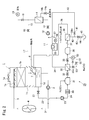
本実施の形態では、ブロー水を処理する水処理装置にタンクを設けているが、これらはなくてもよい。本発明では、図2に示すように、流入負荷を平準化するために、逆洗排水、濃縮水、循環水、洗浄排水をいったん水槽55に貯留し、ポンプ56及び配管57を介して定量にて配管11や冷却塔に戻してもよい。
逆洗排水、循環水、洗浄排水や濃縮水の水質をセンサで検出し、規定濃度以上の場合には回収を行わないようにしてもよい。
上記のように、この実施の形態では、前処理膜装置33からの逆洗排水や循環水、濃縮水、薬液洗浄廃水が回収される。RO膜装置38からのフラッシング排水、薬液洗浄廃水、循環水が回収される。
上記説明では前処理膜装置33とRO膜装置38が用いられているが、その他の膜、濾過手段が用いられてもよく、それらの洗浄手段、濃縮水等の全部が回収対象となる。洗浄廃水は排水ラインから分岐するラインを介して冷却塔に供給するようにしても良いし、直接冷却塔側へ供給ラインを介して供給するようにしても良い。濃縮水も同様であり、循環ラインから分岐させて冷却塔に供給するようにしても良いし、濃縮水の全部を冷却塔へ供給するようにしても良い。
上記実施の形態では、濃縮水、逆洗排水等をサイドフィルタ14への循環送水用配管11に返送しているが、他の箇所に返送してもよく、ピット1d内に直接、例えばピット1dにおける配管11の接続部近傍としてもよい。返送先をピット1dの配管11の接続部つまり吸い込み口近辺に配置することで、濁質を含む水がピット内に入った際に直ちに配管11を介してサイドフィルタ14へ送られて処理されることになる。水質によっては配管3を介して返送してもよい。
上記実施の形態では、回収用の水処理装置が、濾過器30と、UF膜装置などの前処理膜装置33と、RO膜装置38とを備えているが、濾過器、UF膜、MF膜、ナノ濾過膜及びRO膜の1つ又は任意の2以上の組み合せであってもよい。
本発明では、逆洗排水、循環水、洗浄排水、濃縮水の濁質量が1000度未満であることが好ましい。逆洗排水の濁度は瞬間的に最大300度程度になるが、濾過を行うことで、1度以下にまで低下する。逆洗排水、循環濃縮水、洗浄排水のpHは2~12であることが好ましい。
上記実施の形態では冷却塔ブロー水を膜分離装置で処理して回収するようにしているが、工場、プラント等に設置された用水や排水等の膜処理設備の洗浄排水等であっても、冷却塔給水として適用できるものがあれば、上記水処理装置25で処理し、冷却塔1の冷却水として利用してもよい。但し、冷却塔ブロー水であれば、洗浄廃水中の濁質分が同じ成分であるため、適用しやすいというメリットがある。
上記実施の形態では、ブロー配管22を介して水処理装置へ送っているが、ポンプ2の圧力を利用して熱交換器への送り配管3や戻り配管5の位置から送ることもできる。
[実施例1]
千葉市の工業用水を原水とする循環水量5,000m3/h、保有水量1,000m3/hの冷却塔において、濃縮倍率が3.5倍で処理を行っている冷却塔ブロー水の回収処理を行った。
千葉市の工業用水を原水とする循環水量5,000m3/h、保有水量1,000m3/hの冷却塔において、濃縮倍率が3.5倍で処理を行っている冷却塔ブロー水の回収処理を行った。
冷却水の分散剤処理には、アクリル酸とAMPSの共重合物(モル比70:30)、平均重量分子量10,000の分散剤を用いた。初期の系内の分散剤保持濃度は3mg/Lであった。スライム防止剤として、WO11/125762記載のアルカリとスルファミン酸、次亜塩素酸の混合剤を用いた。系内の初期結合塩素濃度が1.0mg/Lになるようにスライム防止剤を添加した。冷却塔にはサイドフィルタとして、栗田工業製ライトフィルターが設置され、150m3/hで濾過を行い、系内の濁質を所定量除去した。
回収処理のフローは、図1の水処理装置25の通り、ストレーナ、MF装置、RO膜装置であり、ブロー水量20m3/hの全量を回収処理した。ストレーナのメッシュは400μm、MF膜はクラレ製ピューリアGS(親水化PVDF、孔径0.02μm、外圧式)を用いた。RO膜は栗田工業株式会社製KROA-2032-SN(ポリアミド超低圧RO膜)を用いた。MF装置の逆洗頻度は30分とし、逆洗時に次亜塩素酸ナトリウムを100mg/Lで添加した。MF装置の逆洗水は冷却塔に戻した。MF装置の逆洗水を戻すことにより、水回収率は100%になった。1回あたりの逆洗水量は1m3であった。
ブロー水のpHは8.5~8.7であったが、RO膜装置の前で硫酸を添加し、pHを5.5になるようにした。3ヵ月ごとに、RO膜装置の水量低下に伴い、pH11に調整した水酸化ナトリウム液でRO膜装置を洗浄し、洗浄後の液は冷却塔に戻した。洗浄液の水量は4m3であった。RO膜装置の水回収率は70~75%で推移した。逆洗水及び洗浄排水の回収によって、洗浄処理が水回収率に影響せず、トータルの水回収率は70~75%で推移した。
逆洗時の濁質はサイドフィルタで除去され、濁度は5~7度で安定的に推移した。逆洗時に添加された次亜塩素酸ナトリウムは冷却塔内で消費され、塩素濃度は0.1~0.2mg/Lで推移した。結合塩素濃度は0.8~1.0mg/Lで推移した。
[比較例1]
MF装置の逆洗排水、RO膜装置の洗浄排水を系外に排出し、冷却塔に戻さないこと以外は実施例1と同様の処理を行った。MF膜の水回収率は90%であり、RO膜装置の水回収率は68~73%であった。そのため、トータルの水回収率は61~65%で推移した。
MF装置の逆洗排水、RO膜装置の洗浄排水を系外に排出し、冷却塔に戻さないこと以外は実施例1と同様の処理を行った。MF膜の水回収率は90%であり、RO膜装置の水回収率は68~73%であった。そのため、トータルの水回収率は61~65%で推移した。
逆洗排水、洗浄排水を系外に排出するために還元処理、pH中和処理が必要となった。
[実施例2]
冷却塔システムにサイドフィルタ14を設置しないこと以外は実施例1と同様の冷却塔システムにおいて、実施例1と同一の処理を行った。その結果、系内の濁質量が徐々に増加し、10日で50度以上になったので、処理を停止した。
冷却塔システムにサイドフィルタ14を設置しないこと以外は実施例1と同様の冷却塔システムにおいて、実施例1と同一の処理を行った。その結果、系内の濁質量が徐々に増加し、10日で50度以上になったので、処理を停止した。
[実施例3]
冷却塔の保有水量を100m3としたこと以外は実施例1と同様の処理を行った。MF装置の逆洗水の返送による影響は見られなかった。但し、RO膜装置の洗浄排水を戻した際、pHが変動し、系内でCaCO3スケールが析出したので、返送を停止した。
冷却塔の保有水量を100m3としたこと以外は実施例1と同様の処理を行った。MF装置の逆洗水の返送による影響は見られなかった。但し、RO膜装置の洗浄排水を戻した際、pHが変動し、系内でCaCO3スケールが析出したので、返送を停止した。
[考察]
以上の通り、本発明の循環冷却水の処理方法及び処理装置によれば、回収処理中の逆洗排水、洗浄排水を冷却塔に戻すことにより、水回収率を高くすることができ、追加の排水処理が不要となり、経済的に優れ、高回収率で安定処理が可能となった。
以上の通り、本発明の循環冷却水の処理方法及び処理装置によれば、回収処理中の逆洗排水、洗浄排水を冷却塔に戻すことにより、水回収率を高くすることができ、追加の排水処理が不要となり、経済的に優れ、高回収率で安定処理が可能となった。
本発明を特定の態様を用いて詳細に説明したが、本発明の意図と範囲を離れることなく様々な変更が可能であることは当業者に明らかである。
本出願は、2015年3月31日付で出願された日本特許出願2015-072960に基づいており、その全体が引用により援用される。
本出願は、2015年3月31日付で出願された日本特許出願2015-072960に基づいており、その全体が引用により援用される。
1 冷却塔
4 熱交換器
14 サイドフィルタ
25 水処理装置
30 濾過器
33 前処理膜装置
38 RO膜装置
4 熱交換器
14 サイドフィルタ
25 水処理装置
30 濾過器
33 前処理膜装置
38 RO膜装置
Claims (16)
- 膜分離装置の逆洗排水、洗浄排水、循環水及び濃縮水の少なくとも1つよりなる膜分離装置排出水の一部又は全部を冷却塔に供給することを特徴とする水処理方法。
- 請求項1において、膜分離装置は、前処理膜装置と逆浸透膜装置とを含み、該前処理装置は、少なくとも精密濾過膜又は限外濾過膜を有することを特徴とする水処理方法。
- 請求項1又は2において、前記冷却塔は冷却水の少なくとも一部を循環濾過するための濾過装置を備えることを特徴とする水処理方法。
- 請求項1又は2において、前記膜分離装置排出水を濾過処理した後に冷却塔内に供給することを特徴とする水処理方法。
- 請求項4において、該濾過処理を、前記冷却塔に設けられた冷却水の少なくとも一部を循環濾過するための濾過装置で行うことを特徴とする水処理方法。
- 請求項1又は2において、冷却塔には、冷却塔から冷却水の少なくとも一部を循環濾過するための濾過装置へ送水する送水配管が接続されており、
前記膜分離装置排出水を、該送水配管、又は冷却塔内の該送水配管接続部の近傍に供給することを特徴とする水処理方法。 - 請求項1ないし6のいずれか1項において、前記膜分離装置排出水をタンクに一時的に貯留してから、冷却塔に供給することを特徴とする水処理方法。
- 請求項1ないし7のいずれか1項において、冷却塔のブロー水を前記膜分離装置に供給することを特徴とする水処理方法。
- 膜分離装置を有する水処理装置であって、
該膜分離装置の逆洗排水、洗浄排水、循環水及び濃縮水の少なくとも1つよりなる膜分離装置排出水の一部又は全部を冷却塔に供給する供給器を備えたことを特徴とする水処理装置。 - 請求項9において、膜分離装置は、前処理膜装置と逆浸透膜装置とを含み、該前処理装置は、少なくとも精密濾過膜又は限外濾過膜を有することを特徴とする水処理装置。
- 請求項9又は10において、前記冷却塔は冷却水の少なくとも一部を循環濾過するための濾過装置を備えることを特徴とする水処理装置。
- 請求項9又は10において、前記膜分離装置排出水を濾過装置で濾過処理した後に冷却塔内に供給することを特徴とする水処理装置。
- 請求項12において、該濾過装置は、冷却塔に設けられた冷却水の少なくとも一部を循環濾過するための濾過装置であることを特徴とする水処理装置。
- 請求項9又は10において、冷却塔には、冷却塔から冷却水の少なくとも一部を循環濾過するための濾過装置へ送水する送水配管が接続されており、
前記膜分離装置排出水を、該送水配管、又は冷却塔内の該送水配管接続部の近傍に供給することを特徴とする水処理装置。 - 請求項9ないし14のいずれか1項において、前記膜分離装置排出水を一時的に貯留してから前記冷却塔に供給するための貯留器を備えたことを特徴とする水処理装置。
- 請求項9ないし15のいずれか1項において、前記冷却塔のブロー水を前記膜分離装置に供給する供給器を備えたことを特徴とする水処理装置。
Priority Applications (2)
| Application Number | Priority Date | Filing Date | Title |
|---|---|---|---|
| SG11201707887RA SG11201707887RA (en) | 2015-03-31 | 2016-03-11 | Water treatment method and apparatus |
| CN201680017517.9A CN107406277B (zh) | 2015-03-31 | 2016-03-11 | 水处理方法及装置 |
Applications Claiming Priority (2)
| Application Number | Priority Date | Filing Date | Title |
|---|---|---|---|
| JP2015-072960 | 2015-03-31 | ||
| JP2015072960A JP6305368B2 (ja) | 2015-03-31 | 2015-03-31 | 水処理方法及び装置 |
Publications (1)
| Publication Number | Publication Date |
|---|---|
| WO2016158312A1 true WO2016158312A1 (ja) | 2016-10-06 |
Family
ID=57006052
Family Applications (1)
| Application Number | Title | Priority Date | Filing Date |
|---|---|---|---|
| PCT/JP2016/057732 Ceased WO2016158312A1 (ja) | 2015-03-31 | 2016-03-11 | 水処理方法及び装置 |
Country Status (5)
| Country | Link |
|---|---|
| JP (1) | JP6305368B2 (ja) |
| CN (1) | CN107406277B (ja) |
| SG (1) | SG11201707887RA (ja) |
| TW (1) | TWI699235B (ja) |
| WO (1) | WO2016158312A1 (ja) |
Cited By (3)
| Publication number | Priority date | Publication date | Assignee | Title |
|---|---|---|---|---|
| CN107321186B (zh) * | 2017-08-16 | 2018-04-13 | 北京北控海创科技有限公司 | 一种纳滤、反渗透膜的高渗透压在线反向清洗方法及装置 |
| CN109879397A (zh) * | 2019-03-01 | 2019-06-14 | 武汉纺织大学 | 一种次氯酸钠废水处理设备及处理工艺 |
| CN112459854A (zh) * | 2020-11-16 | 2021-03-09 | 湖南华润电力鲤鱼江有限公司 | 一种汽轮机组用的循环冷却水系统及冷却方法 |
Families Citing this family (9)
| Publication number | Priority date | Publication date | Assignee | Title |
|---|---|---|---|---|
| JP6830413B2 (ja) * | 2017-01-13 | 2021-02-17 | 日鉄エンジニアリング株式会社 | 二酸化炭素の回収設備、及び、二酸化炭素の回収方法 |
| WO2018159299A1 (ja) * | 2017-03-01 | 2018-09-07 | 栗田工業株式会社 | 冷却塔システム |
| WO2018159300A1 (ja) * | 2017-03-01 | 2018-09-07 | 栗田工業株式会社 | 冷却塔システム |
| JP2019025397A (ja) * | 2017-07-27 | 2019-02-21 | 住友電気工業株式会社 | 含油海水の処理装置及び処理方法 |
| JP6468384B1 (ja) * | 2018-03-14 | 2019-02-13 | 栗田工業株式会社 | 水処理装置 |
| JP6590016B2 (ja) * | 2018-03-20 | 2019-10-16 | 栗田工業株式会社 | 逆浸透処理方法及び装置 |
| JP7567360B2 (ja) * | 2020-10-27 | 2024-10-16 | 栗田工業株式会社 | 排ガス処理設備排水の処理装置 |
| CN112723609A (zh) * | 2021-01-19 | 2021-04-30 | 涧纳(上海)环保科技有限公司 | 一种循环冷却水排污水的回用处理方法及装置 |
| JP7831043B2 (ja) * | 2022-03-18 | 2026-03-17 | 栗田工業株式会社 | 冷却塔の運転管理方法、運転管理システム及び運転管理用プログラム |
Citations (6)
| Publication number | Priority date | Publication date | Assignee | Title |
|---|---|---|---|---|
| JPS513038A (ja) * | 1974-06-27 | 1976-01-12 | Nippon Steel Corp | Kitaijunkanreikyakusochikeino mohatsuseiboshihoho |
| JP2000126781A (ja) * | 1998-10-20 | 2000-05-09 | Aquas Corp | 細菌性スライム障害の予測方法及び防止方法 |
| JP2002310595A (ja) * | 2001-04-12 | 2002-10-23 | Ebara Corp | 冷却装置 |
| JP2003001256A (ja) * | 2001-06-25 | 2003-01-07 | Kurita Water Ind Ltd | 循環冷却水の処理方法 |
| JP2004188270A (ja) * | 2002-12-09 | 2004-07-08 | Kurita Water Ind Ltd | 沈降性懸濁物含有水の濾過方法及び濾過設備 |
| JP2011156483A (ja) * | 2010-02-01 | 2011-08-18 | Asahi Kasei Chemicals Corp | 水回収システム |
Family Cites Families (5)
| Publication number | Priority date | Publication date | Assignee | Title |
|---|---|---|---|---|
| JP2002147993A (ja) * | 2000-11-09 | 2002-05-22 | Aquas Corp | 開放型冷却塔及びこれに濾過処理した冷却水を戻す方法 |
| JP3757888B2 (ja) * | 2002-03-27 | 2006-03-22 | 栗田工業株式会社 | 水処理機器の運転管理方法 |
| JP5603740B2 (ja) * | 2010-11-02 | 2014-10-08 | オルガノ株式会社 | ろ過システム |
| US20130056413A1 (en) * | 2011-09-01 | 2013-03-07 | General Electric Company | Membrane treatment of cooling tower blow down water |
| CN203936491U (zh) * | 2014-03-19 | 2014-11-12 | 常州市长昊机械有限公司 | 一种冷却水循环装置 |
-
2015
- 2015-03-31 JP JP2015072960A patent/JP6305368B2/ja not_active Expired - Fee Related
-
2016
- 2016-03-11 SG SG11201707887RA patent/SG11201707887RA/en unknown
- 2016-03-11 CN CN201680017517.9A patent/CN107406277B/zh active Active
- 2016-03-11 WO PCT/JP2016/057732 patent/WO2016158312A1/ja not_active Ceased
- 2016-03-22 TW TW105108829A patent/TWI699235B/zh active
Patent Citations (6)
| Publication number | Priority date | Publication date | Assignee | Title |
|---|---|---|---|---|
| JPS513038A (ja) * | 1974-06-27 | 1976-01-12 | Nippon Steel Corp | Kitaijunkanreikyakusochikeino mohatsuseiboshihoho |
| JP2000126781A (ja) * | 1998-10-20 | 2000-05-09 | Aquas Corp | 細菌性スライム障害の予測方法及び防止方法 |
| JP2002310595A (ja) * | 2001-04-12 | 2002-10-23 | Ebara Corp | 冷却装置 |
| JP2003001256A (ja) * | 2001-06-25 | 2003-01-07 | Kurita Water Ind Ltd | 循環冷却水の処理方法 |
| JP2004188270A (ja) * | 2002-12-09 | 2004-07-08 | Kurita Water Ind Ltd | 沈降性懸濁物含有水の濾過方法及び濾過設備 |
| JP2011156483A (ja) * | 2010-02-01 | 2011-08-18 | Asahi Kasei Chemicals Corp | 水回収システム |
Cited By (3)
| Publication number | Priority date | Publication date | Assignee | Title |
|---|---|---|---|---|
| CN107321186B (zh) * | 2017-08-16 | 2018-04-13 | 北京北控海创科技有限公司 | 一种纳滤、反渗透膜的高渗透压在线反向清洗方法及装置 |
| CN109879397A (zh) * | 2019-03-01 | 2019-06-14 | 武汉纺织大学 | 一种次氯酸钠废水处理设备及处理工艺 |
| CN112459854A (zh) * | 2020-11-16 | 2021-03-09 | 湖南华润电力鲤鱼江有限公司 | 一种汽轮机组用的循环冷却水系统及冷却方法 |
Also Published As
| Publication number | Publication date |
|---|---|
| JP6305368B2 (ja) | 2018-04-04 |
| CN107406277A (zh) | 2017-11-28 |
| CN107406277B (zh) | 2021-01-12 |
| JP2016190224A (ja) | 2016-11-10 |
| SG11201707887RA (en) | 2017-10-30 |
| TW201703846A (zh) | 2017-02-01 |
| TWI699235B (zh) | 2020-07-21 |
Similar Documents
| Publication | Publication Date | Title |
|---|---|---|
| JP6305368B2 (ja) | 水処理方法及び装置 | |
| CN106414344B (zh) | 循环冷却水系统中的冷却水处理药剂的浓度调整方法、冷却排出水的回收方法以及水处理装置 | |
| KR101744400B1 (ko) | 역삼투막 필터의 세정 장치 | |
| JP5773013B1 (ja) | 冷却排出水の回収方法及び回収装置 | |
| JP2008229418A (ja) | 工業用水の処理方法および処理装置 | |
| KR101928212B1 (ko) | 역삼투막 세정 방법 | |
| CN103328079B (zh) | 膜组件的洗涤方法、造水方法以及造水装置 | |
| US20070138096A1 (en) | Systems and methods for controlling contaminate levels of processed water and maintaining membranes | |
| US11186499B2 (en) | Methods of inhibiting fouling in liquid systems | |
| US11130694B2 (en) | Recovery method for discharged cooling water | |
| JP2017113729A (ja) | 膜洗浄剤、膜洗浄液及び膜の洗浄方法 | |
| JP6550851B2 (ja) | 逆浸透膜を用いた水処理方法及び水処理装置 | |
| KR20240064748A (ko) | 살생물제 조성물 및 방법 | |
| JP4650740B2 (ja) | 水処理システムの運転方法 | |
| KR101711516B1 (ko) | 증기를 이용한 막모듈 세정장치 및 방법 | |
| WO2012138900A1 (en) | Use of rhamnolipids in the water treatment industry | |
| JP4850467B2 (ja) | 膜脱気装置の洗浄方法 | |
| CN205275367U (zh) | 一种柴油发电机用冷却循环水系统 | |
| JP2005046762A (ja) | 水処理方法および装置 | |
| JP2005046801A (ja) | 水処理方法および装置 | |
| JP7354744B2 (ja) | 排水利用システム | |
| JP4842772B2 (ja) | 重亜硫酸ナトリウムの貯蔵装置 | |
| TWI893203B (zh) | 除鹽裝置的運轉方法 | |
| JP7427890B2 (ja) | 濃縮システム | |
| US20240025780A1 (en) | Method for eliminating the use of chemical products in pre-treatment in seawater desalination plants based on reverse osmosis |
Legal Events
| Date | Code | Title | Description |
|---|---|---|---|
| 121 | Ep: the epo has been informed by wipo that ep was designated in this application |
Ref document number: 16772196 Country of ref document: EP Kind code of ref document: A1 |
|
| WWE | Wipo information: entry into national phase |
Ref document number: 11201707887R Country of ref document: SG |
|
| NENP | Non-entry into the national phase |
Ref country code: DE |
|
| 122 | Ep: pct application non-entry in european phase |
Ref document number: 16772196 Country of ref document: EP Kind code of ref document: A1 |