WO2016158255A1 - 作業機械の周辺監視装置 - Google Patents
作業機械の周辺監視装置 Download PDFInfo
- Publication number
- WO2016158255A1 WO2016158255A1 PCT/JP2016/057236 JP2016057236W WO2016158255A1 WO 2016158255 A1 WO2016158255 A1 WO 2016158255A1 JP 2016057236 W JP2016057236 W JP 2016057236W WO 2016158255 A1 WO2016158255 A1 WO 2016158255A1
- Authority
- WO
- WIPO (PCT)
- Prior art keywords
- guide information
- distance
- work machine
- image
- periphery monitoring
- Prior art date
- Legal status (The legal status is an assumption and is not a legal conclusion. Google has not performed a legal analysis and makes no representation as to the accuracy of the status listed.)
- Ceased
Links
Images





Classifications
-
- E—FIXED CONSTRUCTIONS
- E02—HYDRAULIC ENGINEERING; FOUNDATIONS; SOIL SHIFTING
- E02F—DREDGING; SOIL-SHIFTING
- E02F9/00—Component parts of dredgers or soil-shifting machines, not restricted to one of the kinds covered by groups E02F3/00 - E02F7/00
- E02F9/26—Indicating devices
- E02F9/261—Surveying the work-site to be treated
-
- E—FIXED CONSTRUCTIONS
- E02—HYDRAULIC ENGINEERING; FOUNDATIONS; SOIL SHIFTING
- E02F—DREDGING; SOIL-SHIFTING
- E02F9/00—Component parts of dredgers or soil-shifting machines, not restricted to one of the kinds covered by groups E02F3/00 - E02F7/00
- E02F9/26—Indicating devices
-
- E—FIXED CONSTRUCTIONS
- E02—HYDRAULIC ENGINEERING; FOUNDATIONS; SOIL SHIFTING
- E02F—DREDGING; SOIL-SHIFTING
- E02F9/00—Component parts of dredgers or soil-shifting machines, not restricted to one of the kinds covered by groups E02F3/00 - E02F7/00
- E02F9/24—Safety devices, e.g. for preventing overload
-
- G—PHYSICS
- G06—COMPUTING OR CALCULATING; COUNTING
- G06V—IMAGE OR VIDEO RECOGNITION OR UNDERSTANDING
- G06V20/00—Scenes; Scene-specific elements
- G06V20/50—Context or environment of the image
- G06V20/52—Surveillance or monitoring of activities, e.g. for recognising suspicious objects
-
- H—ELECTRICITY
- H04—ELECTRIC COMMUNICATION TECHNIQUE
- H04N—PICTORIAL COMMUNICATION, e.g. TELEVISION
- H04N23/00—Cameras or camera modules comprising electronic image sensors; Control thereof
- H04N23/57—Mechanical or electrical details of cameras or camera modules specially adapted for being embedded in other devices
-
- H—ELECTRICITY
- H04—ELECTRIC COMMUNICATION TECHNIQUE
- H04N—PICTORIAL COMMUNICATION, e.g. TELEVISION
- H04N23/00—Cameras or camera modules comprising electronic image sensors; Control thereof
- H04N23/90—Arrangement of cameras or camera modules, e.g. multiple cameras in TV studios or sports stadiums
-
- H—ELECTRICITY
- H04—ELECTRIC COMMUNICATION TECHNIQUE
- H04N—PICTORIAL COMMUNICATION, e.g. TELEVISION
- H04N7/00—Television systems
- H04N7/18—Closed-circuit television [CCTV] systems, i.e. systems in which the video signal is not broadcast
-
- H—ELECTRICITY
- H04—ELECTRIC COMMUNICATION TECHNIQUE
- H04N—PICTORIAL COMMUNICATION, e.g. TELEVISION
- H04N7/00—Television systems
- H04N7/18—Closed-circuit television [CCTV] systems, i.e. systems in which the video signal is not broadcast
- H04N7/181—Closed-circuit television [CCTV] systems, i.e. systems in which the video signal is not broadcast for receiving images from a plurality of remote sources
Definitions
- the present invention relates to a work machine periphery monitoring apparatus capable of displaying guideline information that can improve work efficiency.
- a plurality of cameras are installed behind the vehicle body or on the side of the vehicle body so that the operator can visually recognize obstacles around the vehicle body. And the image which the camera imaged is projected on the monitor in the cab of a working machine as a single camera image.
- an apparatus that generates a bird's-eye view image by synthesizing the images of each camera after converting the images of each camera into an upper viewpoint so that 360 degrees around the vehicle body can be monitored simultaneously.
- a device that displays a single camera image captured by a camera selected by an operator on a monitor (see Patent Document 1).
- a plurality of concentric circular broken lines may be displayed in the overhead image from the turning center of the upper turning body.
- the plurality of concentric circular broken lines merely indicate the distance from the turning center of the upper turning body. Therefore, the operator stops at a position of 90 degrees or 180 degrees to the left or right with respect to an object other than the hydraulic excavator, for example, the direction of the dump truck, specifically, the hydraulic excavator that is performing excavation work, depending on the situation of the work.
- the dump truck stops or not it is necessary to visually check the actual dump truck or to estimate the stop position from the displayed overhead image.
- there is a problem that the working efficiency is poor because the accuracy of the direction is not increased.
- the present invention has been made in view of the above, and an object thereof is to provide a work machine periphery monitoring device capable of displaying guideline information capable of improving work efficiency.
- a work machine periphery monitoring device is a work machine periphery monitoring device provided in a work machine having a work machine on an upper swing body.
- a plurality of cameras that acquire the surroundings of the work machine, an image processing unit that generates an overhead image based on images captured by the plurality of cameras, and an image of one of the plurality of cameras.
- a display unit for displaying a single camera image and / or the bird's-eye view image, a straight line portion having a predetermined length extending perpendicularly to four straight lines extending in the front-rear and left-right directions from the turning center of the upper turning body, and the straight line
- a display control unit for displaying distance guide information formed by an arcuate portion of the same circle connecting each end of the unit on the single camera image and / or on the overhead image.
- the distance guide information includes a distance from the turning center of the upper swing body to the left and right front-rear direction at a rear portion of the upper swing body.
- First distance guide information that is the distance to the counter weight
- second distance guide information that is further increased by a predetermined distance from the first distance guide information, and prohibits the approach of an external work vehicle, and the work implement is maximized.
- third distance guide information indicating a turning area of the work machine in a state where the work implement is in a state of being.
- the predetermined width is a width in a left-right direction of the upper swing body.
- the work machine periphery monitoring apparatus is characterized in that, in the above-described invention, direction guide information connecting between the ends of the straight portions and the center is added to the distance guide information.
- the work machine periphery monitoring device includes, in the above invention, a guideline display setting unit configured to set display / non-display of the direction guide information, and the display control unit includes the guide display setting unit.
- the direction guide information is displayed / hidden according to the setting.
- the work machine periphery monitoring device is characterized in that, in the above invention, the direction guide information is position information at a ground surface level.
- the work machine periphery monitoring device is characterized in that, in the above invention, the display unit is provided in a remote control seat, a control room, or a portable terminal.
- the distance guide information is displayed on the image from the reference position of the upper swing body toward the periphery of the upper swing body, the positional relationship with the object positioned around the work machine And its orientation can be read easily, and work efficiency can be improved.
- FIG. 1 is a side view showing an overall configuration of a hydraulic excavator on which a working machine periphery monitoring device according to an embodiment of the present invention is mounted.
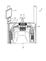
- FIG. 2 is a diagram showing the internal arrangement of the cab.
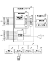
- FIG. 3 is a block diagram showing the detailed configuration of the entire control system of the excavator and the peripheral monitoring controller.
- FIG. 4 is an explanatory diagram illustrating the overhead image generation process performed by the overhead image generation unit.
- FIG. 5 is a side view showing the arrangement of the cameras.
- FIG. 6 is a plan view schematically showing the arrangement of the cameras.
- FIG. 7 is a side view showing the arrangement of the radar.
- FIG. 8 is a plan view schematically showing the arrangement of the radar.
- FIG. 1 is a side view showing an overall configuration of a hydraulic excavator on which a working machine periphery monitoring device according to an embodiment of the present invention is mounted.
- FIG. 2 is a diagram showing the internal arrangement of the cab.
- FIG. 9 is a diagram illustrating a display example of an overhead image and a single camera image.
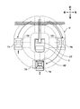
- FIG. 10 is a diagram illustrating a concept of guide information having a straight line portion.
- FIG. 11 is a diagram illustrating a display example of a bird's-eye view image and a single camera image on which guide information having a straight line portion is displayed.
- FIG. 12 is a diagram illustrating an example of work in the case of using guide information having a straight line portion.
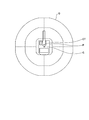
- FIG. 13 is a diagram illustrating a display example of guide information when the center of the overhead image is the center of gravity of the upper swing body.
- FIG. 14 is a diagram illustrating an example in which the periphery monitoring monitor is provided in the remote operation seat.
- FIG. 15 is a diagram illustrating an example in which the periphery monitoring monitor is provided in the mobile terminal.
- FIG. 1 is a side view showing an overall configuration of a hydraulic excavator on which a working machine periphery monitoring device according to an embodiment of the present invention is mounted.
- This hydraulic excavator 1 is a large hydraulic excavator such as a mining excavator used in a mine or the like shown as an example of a work machine.
- the hydraulic excavator 1 includes a self-propelled lower traveling body 2, an upper revolving body 3 that is pivotably installed on the lower traveling body 2, and a working machine that bends and undulates at the front center of the upper revolving body 3. 4.
- the work machine 4 includes a boom 4a, an arm 4b, a bucket 4c, a boom cylinder 4d, an arm cylinder 4e, and a bucket cylinder 4f.
- a base end portion of the boom 4a is rotatably connected to the upper swing body 3.
- the distal end portion of the boom 4a is rotatably connected to the proximal end portion of the arm 4b.
- the tip of the arm 4b is rotatably connected to the bucket 4c.
- the boom cylinder 4d, the arm cylinder 4e, and the bucket cylinder 4f are hydraulic cylinders that are driven by hydraulic oil discharged from a hydraulic pump.
- the boom cylinder 4d operates the boom 4a.
- the arm cylinder 4e operates the arm 4b.
- the bucket cylinder 4f is connected to the bucket 4c via a link member, and operates the bucket 4c.
- the bucket 4c operates as the cylinder rod of the bucket cylinder 4f expands and contracts.
- the opening of the bucket 4 c functions as a backhoe that faces the turning center, but the opening of the bucket 4 c may function as a front shovel that faces outward from the turning center.
- a cab 6 is installed on the left side of the front part of the upper swing body 3 via a cab base 5.
- a power container 7 is mounted on the rear part of the upper swing body 3.
- an engine, a hydraulic pump, a radiator, an oil cooler, and the like are accommodated.
- a counterweight 8 is attached to the rear end portion of the upper swing body 3.
- An elevating ladder 9 is disposed on the left side of the upper swing body 3 so as to be positioned behind the cab base 5. The lifting ladder 9 supports the lifting and lowering of the driver and the maintenance worker with respect to the upper swing body 3.
- FIG. 2 is a diagram showing the internal arrangement of the cab 6.
- the operation levers 11 and 12 are disposed on the left and right sides of the operator seat 10 in the cab 6.
- the operation lever 11 is disposed on the left hand side when the operator is seated on the operator seat 10.
- the operation lever 11 corresponds to the turning operation of the upper swing body 3 and the operation of the arm 4b.
- the operation lever 11 is operated to the left and right, the upper swing body 3 is turned to the left and right, and when the operation lever 11 is operated up and down, the arm 4b. Rotates in the front-rear direction.
- the operation lever 12 corresponds to the operation of the boom 4a and the operation of the bucket 4c.
- the traveling lever 13 can move forward and backward of the crawler track on the left side of the lower traveling body 2 according to the operation. Further, the traveling lever 14 can perform forward and backward movement of the right crawler belt of the lower traveling body 2 in accordance with an operation. If the traveling levers 13 and 14 are operated at the same time, the left and right crawler belts are driven simultaneously, and the entire excavator 1 can be moved forward and backward.
- the periphery monitoring monitor 15 is an input / output device formed by a touch panel, and can display at least the surroundings of the excavator 1 acquired by a plurality of cameras as an overhead image and a single camera image.
- the monitor 16 is an input / output device having a liquid crystal display unit and a key input unit.
- the monitor 16 can display various information including the state of the engine and the hydraulic pump. For example, the monitor 16 can display warning information indicating an engine water temperature, an oil temperature, a remaining amount of combustion, an abnormality of the device, and the like.
- the buzzer 17 issues a warning when an obstacle is detected by a plurality of radars. When an obstacle is detected, this obstacle information is also displayed on the image of the periphery monitoring monitor 15 described above.
- FIG. 3 is a block diagram showing a configuration of the entire control system of the hydraulic excavator 1.
- the periphery monitoring controller 40 is connected to a CAN 41 that is one of in-vehicle networks.
- a communication controller 42, a monitor controller 43, an engine controller 44, a pump controller 45, etc. are connected to the CAN 41.
- a camera group C including a plurality of cameras C1 to C7, a radar group R including a plurality of radars R1 to R8, a periphery monitoring monitor 15, and a buzzer 17 are connected to the periphery monitoring controller 40.
- the periphery monitoring controller 40 performs periphery monitoring control.
- the periphery monitoring controller 40 includes an image processing unit 51, an obstacle processing unit 52, and a display control unit 53. Further, the image processing unit 51 includes an overhead image generation unit 54 and an image composition unit 55.
- the overhead image generation unit 54 generates the overhead image 61 based on the images obtained from the cameras C1 to C7. As shown in FIG. 4, the overhead image generation unit 54 converts the images P1 to P7 obtained from the cameras C1 to C7 into an upper viewpoint image. That is, the overhead image generation unit 54 converts the image into an image viewed from a predetermined virtual viewpoint located above the excavator 1. Specifically, the bird's-eye view image generation unit 54 performs image conversion to be projected from a virtual viewpoint above the excavator 1 onto a predetermined virtual projection plane corresponding to the ground level GL.
- the overhead image generation unit 54 cuts out the converted images P11 to P17 corresponding to the regions E1 to E7 of the frame displaying the overhead image, and synthesizes the converted images P11 to P17 in the frame.
- An image P corresponding to a plan view of the excavator 1 is pasted in advance on the overhead image 61 generated by the overhead image generation unit 54.
- the obstacle processing unit 52 detects an obstacle based on the information of the radars R1 to R8.
- the obstacle processing unit 52 sounds the buzzer 17 to notify the obstacle, and outputs obstacle information such as the size and position of the detected obstacle to the image composition unit 55.
- the image composition unit 55 receives the above-described bird's-eye view image 61 and images (single camera images 62) captured by the cameras C1 to C7.
- the image composition unit 55 When the obstacle information is input from the obstacle processing unit 52, the image composition unit 55 generates an image in which the obstacle information is combined with the above-described overhead image 61 and single camera image 62. For example, the obstacle information A1 in the area E4 of FIG.
- the display control unit 53 performs control to display the overhead monitor image 61 input from the image composition unit 55 and the single camera image 62 selected from the images captured by the cameras C1 to C7 on the periphery monitoring monitor 15.
- the monitor controller 43 is connected to the monitor 16.
- the monitor controller 43 performs input / output control of various information such as information transmitted from various sensors via the CAN 41 and information input via the monitor 16.
- the monitor 16 can display, for example, warning information indicating an engine water temperature, an oil temperature, a remaining amount of fuel, a device abnormality, and the like.
- each of the cameras C1 to C7 may be attached to the upper swing body 3.
- each of the cameras C1 to C7 has a visual field range of 120 degrees in the left-right direction (60 degrees left and right) and 96 degrees in the height direction.
- a CCD (Charge-Coupled Device) camera can be used as the camera.
- Each of the cameras C1 to C7 may have a wide dynamic range function.
- the camera C ⁇ b> 1 is provided on the front surface of the cab base 5 which is the lower part of the cab 6 of the upper swing body 3 and images the front of the upper swing body 3.
- the camera C ⁇ b> 2 is provided at the lower right front of the upper swing body 3 and images the right front of the upper swing body 3.
- the camera C3 is provided at the lower part of the right side surface of the upper swing body 3 and images the right rear of the upper swing body 3.
- the camera C ⁇ b> 4 is provided in the lower rear center of the counterweight 8 disposed behind the upper swing body 3 and images the rear of the upper swing body 3.
- the camera C5 is provided at the lower part of the left side surface of the upper swing body 3 and images the left rear of the upper swing body 3.
- the camera C6 is provided on the upper left side surface of the cab base 5 and images the left front of the upper swing body 3.
- the camera C ⁇ b> 7 is provided in the lower part of the power container 7 and images the lower area of the power container 7 and the counterweight 8. Since the imaging ranges of the adjacent cameras C1 to C7 overlap, it is possible to take an image of the outer circumference of 360 degrees near the excavator.
- each of the radars R1 to R8 detects the relative position (relative position) and direction between the obstacle and the excavator 1 around the excavator 1.
- the radars R1 to R8 are attached to the outer peripheral portion of the excavator 1 as shown in FIGS.
- each of the radars R1 to R8 has a detection angle of 80 degrees ( ⁇ 40 degrees) in the azimuth (horizontal) direction and 16 degrees ( ⁇ 8 degrees) in the vertical (vertical) direction, and a UWB (maximum detection distance of 15 m or more).
- Ultra Wide Band (radar) radar Ultra Wide Band
- the radar R1 is provided at the lower left end of the front part of the upper swing body 3 and detects an obstacle on the left front side of the upper swing body 3.
- the radar R ⁇ b> 2 is provided at the front lower right end of the upper swing body 3 and detects an obstacle on the right front side of the upper swing body 3. Further, the installation directions of the radars R1 and R2 are adjusted so as not to detect the work machine 4 such as the bucket 4c, and the detection areas of the radars R1 and R2 do not overlap.
- the radar R3 is provided at the lower right side of the upper swing body 3 and detects an obstacle on the right rear side of the upper swing body 3.
- the radar R ⁇ b> 4 is provided at the lower right side of the upper swing body 3 and detects an obstacle on the right front side of the upper swing body 3.
- the radar R3 is adjacent to the radar R4 and is disposed in front of the position of the radar R4.
- the radars R3 and R4 detect obstacles on the entire right side of the upper swing body 3 by irradiating radar signals so as to cross each other.
- the radar R5 is provided below the counterweight 8 of the upper swing body 3 and detects an obstacle on the left rear of the upper swing body 3.
- the radar R6 is provided below the counterweight 8 and detects an obstacle on the right rear side of the upper swing body 3.
- the radar R5 is adjacent to the radar R6 and is arranged on the right side with respect to the position of the radar R6.
- the radars R5 and R6 detect obstacles on the entire rear surface of the upper swing body 3 by irradiating radar signals so as to cross each other.
- the radar R8 is provided on the lower left side of the upper swing body 3 and detects an obstacle on the left front side of the upper swing body 3.
- the radar R ⁇ b> 7 is provided at the lower left side of the upper swing body 3 and detects an obstacle on the left rear side of the upper swing body 3.
- the radar R8 is disposed adjacent to the radar R7 and rearward with respect to the position of the radar R7.
- the radars R8 and R7 detect obstacles on the entire left side of the upper swing body 3 by radiating radar signals so as to cross each other.
- the periphery monitoring monitor 15 shown in FIG. 9 is an example of an initial screen that is displayed first when the key is turned on.
- a bird's-eye view image 61 is displayed in the upper area of the periphery monitoring monitor 15, and a single camera image 62 is displayed in the lower area.
- icons I1 and I2 are displayed on the lower right of the periphery monitoring monitor 15.
- the displayed single camera image 62 is a rear image of the upper swing body 3 captured by the camera C4.
- the icon I1 indicates the seven image positions displayed by the single camera image 62. Since the single camera image 62 shown in FIG.
- FIG. 9 is a rear image, the lower region of the icon I1 corresponding to the rear position of the upper swing body 3 is filled and displayed.
- the dump truck TR exists behind the upper swing body 3.
- the dump truck TR is at a position 180 degrees from the front where the work implement 4 is disposed, and is parked facing outward.
- the bird's-eye view image 61 and the single camera image 62 display guide information D indicating the distance and direction from the upper swing body 3 described later.
- the icon I2 reference display setting unit
- FIG. 10 is a diagram showing the concept of the guide information D.
- the standard information D includes distance standard information D1 and direction standard information D2.
- the guide information D is, for example, position information on the ground level GL. By doing so, it becomes easier to discriminate the positional relationship with the obstacle around the hydraulic excavator in the single camera image 62 described later.
- the distance guide information D1 is information indicating a distance from the turning center CT of the upper swing body 3, and includes first distance guide information D11, second distance guide information D12, and third distance guide information D13.
- the first distance guide information D11 is information indicating the distance from the turning center CT of the upper swing body 3 to the left and right front-rear direction to the end of the counterweight 8 provided at the rear part of the upper swing body 3. That is, when there is an obstacle in the area inside the first distance guide information D11, it means that the hydraulic excavator 1 may collide when turning.
- the second distance guide information D12 is information indicating a distance that is further increased from the first distance guide information D11 by a predetermined distance d1 in the radial direction and prohibits the proximity of an external work vehicle such as the dump truck TR. .
- the predetermined distance d1 is, for example, when the excavator 1 is traveling by operating the traveling levers 13 and 14 toward the stopped dump truck TR, and the dump truck is located inside the second distance guide information D12. This is a distance that can be safely stopped without interrupting the operation of the travel levers 13 and 14 after determining that TR has entered and without entering the dump truck TR inside the first distance guide information D11.
- the predetermined distance d1 is 2 m, for example. Therefore, it is preferable that the second distance guide information D12 is set so that the obstacle processing unit 52 detects an obstacle and issues an alarm such as a buzzer when an obstacle enters the area.
- the third distance guide information D13 is information indicating a distance that is further increased from the second distance guide information D12 by a predetermined distance d2 in the radial direction.
- the third distance guide information D13 is information indicating the limit of the turning area of the work machine 4 in a state where the work machine 4 is extended to the maximum.
- the area between the second distance guide information D12 and the third distance guide information D13 is a work area by the work implement 4. In this case, even if there is a dump truck TR located between the second distance guide information D12 and the third distance guide information D13, the buzzer 17 may not be notified.
- the direction guide information D2 is information indicating the front / rear and left / right directions of the upper swing body 3 from the turning center CT of the upper swing body 3, and includes front reference direction guide information D21, left reference direction guide information D22, and rear reference direction guide. Information D23 and right reference direction guide information D24.
- the direction guide information D2 is a straight line that extends linearly from the turning center CT toward the front / rear / right / left direction of the upper swing body 3 and connects the intersections of the first distance guide information D11 and the third distance guide information D13. .
- the distance guide information D1 will be described in more detail.
- the first distance guide information D11 is the intersection of the front reference direction guide information D21, the left reference direction guide information D22, the rear reference direction guide information D23, and the right reference direction guide information D24 with respect to the guide information D21 to D24.
- Each has four straight portions 101 extending vertically.
- Each of the straight portions 101 has a predetermined length d3.
- the straight line portions 101 are provided at positions spaced equidistantly in the front-rear and left-right directions from the turning center CT.
- the predetermined length d3 coincides with the length in the left-right width direction of the upper swing body of the excavator 1.
- each of the second distance guide information D12 and the third distance guide information D13 includes straight portions 102 and 103 having the same predetermined length d3.
- the 1st distance standard information D11 connects between each end of four straight parts 101 by the same circle centering on turning center CT, respectively, and forms four circular arc parts 111.
- the second distance guide information D12 is formed by connecting the end portions of the four linear portions 102 by the same circle centered on the turning center CT, thereby forming four arc portions 112.
- the third distance guide information D13 is formed by connecting the end portions of the four linear portions 103 by the same circle centering on the turning center CT, thereby forming four arc portions 113.
- parallel placement direction guide information 201 and 202 connecting the end portions of the straight portions 101 to 103 may be provided.
- Two pieces of parallel arrangement direction guide information 201 and 202 are arranged in parallel to the front reference direction guide information D21, the left reference direction guide information D22, the rear reference direction guide information D23, and the right reference direction guide information D24. Therefore, a belt-like portion having a predetermined length d3 with respect to the front / rear / left / right direction of the upper swing body 3 is formed.
- FIG. 11 is a diagram illustrating a display example of the overhead image 61 and the single camera image 62 on which the above-described parallel arrangement direction guide information 201 and 202 are displayed.
- the direction guide information D21 ′, D22 ′, D23 ′, and D24 ′ constituting the direction guide information D2 ′ includes the parallel placement direction guide information 201 and 202 in the direction guide information D21, D22, D23, and D24. It is added.
- the dump truck TR is positioned 180 degrees from the front where the work implement 4 is disposed, facing outward, and positioned outside the second distance guide information D12.
- the straight lines 101 to 103 of the distance guide information D1 and the parallel placement direction guide information 201 and 202 can be displayed in a grid pattern, the direction and direction of the work vehicle such as the dump truck TR (FIG. 10).
- the side of the dump truck or the rear surface is compared with the straight portions 101 to 103, so that the dump truck TR It is possible to confirm whether the vehicle is parked diagonally), and the distance from the excavator can be easily recognized.
- some of the above areas are displayed in a grid pattern, other areas are displayed with arc-shaped lines, making it easy to grasp the distance between the images without complicating the whole overhead view image. .
- the first distance guide information D11, the second distance guide information D12, and the third distance guide information D13 constituting the guide information D described above are displayed in colors or different line types according to the distance.
- the first distance guide information D11 may be displayed as a red dotted line
- the second distance guide information D12 may be displayed as a yellow dotted line
- the third distance guide information D13 may be displayed as a white, green, or blue dotted line.
- the direction guide information D2 between the first distance guide information D11 and the second distance guide information D12 is displayed in the same yellow dotted line as the second distance guide information D12
- the second distance guide information D12 and the third distance guide are displayed.
- the direction guide information D2 between the information D13 and the third distance guide information D13 is preferably displayed in the same green or blue dotted line.
- the guide information D may be information in which marks are arranged instead of lines.
- FIG. 12 is a diagram illustrating an example of work when the above-described guide information D is used.
- the above-described reference information D when the above-described reference information D is used, it is easy to grasp the direction from the turning center CT with respect to the front-rear and left-right directions of the upper turning body 3 and the distance to the entire circumference.
- the distance guide information D1 it is possible to grasp how close the obstacle is to the excavator 1, and by having the straight portions 101 to 103, the dump truck TR can
- the vehicle is stopped horizontally or vertically, it can be confirmed whether or not the dump truck TR is stopped diagonally by comparing the side and back surfaces of the dump truck with the straight portions 101 to 103.
- the central portion of the vessel and the hydraulic excavator 1 are disposed.
- the left 90 degrees, right 90 degrees, and 180 degrees can be easily matched. By doing so, it is possible to efficiently carry out the loading work of the earth and sand onto the dump truck TR by the excavator 1 (when the position of the dump truck TR is deviated from the position described in FIG. 12, the loading is performed). Work efficiency decreases).
- the operator can view the overhead image 61 or the By monitoring the camera image 62 and recognizing the direction with the direction guide information D2, the dump truck TR is sounded when the dump truck TR reaches the appropriate position of the straight line portion 102 of the second distance guide information D12. It is possible to stop the TR operator by notifying that the operator is approaching in a direction parallel to the straight line portion 102. As a result, the dump truck TR can be arranged in an appropriate positional relationship with respect to the linear portion 102. In particular, the position of the vessel of the dump truck TR can be arranged and guided to an appropriate position.
- the guide information D is displayed centering on the turning center CT.
- the present invention is not limited to this, and as shown in FIG.
- the guide information D may be displayed.
- the peripheral monitoring monitor 15 is provided separately from the monitor 16, but the present invention is not limited to this, and the overhead image 61 and the single camera image 62 may be displayed on the monitor 16. Good.
- the periphery monitoring monitor 15 is configured as a touch panel display, a normal display without a built-in touch sensor may be used.
- the overhead view image 61 and the single camera image 62 are displayed on the periphery monitoring monitor 15 at the same time.
- the present invention is not limited to this, and only the overhead view image or only the single camera image is displayed in the periphery. You may comprise so that it may display on the monitoring monitor 15.
- FIG. in the above-described embodiment, the touch panel display 60 is configured such that only the images captured by any one of the cameras 61 to 67 are displayed in the area where the images captured by the cameras 61 to 67 are displayed. However, it may be configured such that two or more images can be displayed simultaneously.
- the periphery monitoring device may be configured with a smaller number of cameras, and more than this.
- the perimeter monitoring device may be configured by the number of cameras.
- the periphery monitoring device is configured such that the radar and the camera cooperate.
- the present invention is not limited to this, and the periphery monitoring device may be configured by the camera alone.
- the present invention may be applied to a hydraulic excavator used in a construction site.
- the configuration in which the periphery monitoring monitor 15 and the buzzer 17 are provided in the driver's seat 6 of the work machine has been described.
- You may provide in the control room which manages and controls the some remote control seat 300 shown in the figure or the some working machine in a mine.
- the remote operation monitor 301 shown in FIG. 14 may be used as a peripheral monitoring monitor.
- the periphery monitoring monitor 15 and the buzzer 17 may be provided in the mobile terminal 302 so that the operator can view an overhead image displayed on the mobile terminal 302.
- the remote operation seat 300 when an overhead image is displayed on the periphery monitoring monitor 15 in the remote operation seat 300 or the control room, or when the portable terminal 302 is used as the periphery monitoring monitor 15 or the buzzer 17, the work machine, the remote operation seat 300.
- a configuration may be employed in which some communication means is provided in each of the control room / portable terminal 302 and the like, and information such as a bird's-eye view image is transmitted and received.
Landscapes
- Engineering & Computer Science (AREA)
- Multimedia (AREA)
- Mining & Mineral Resources (AREA)
- Civil Engineering (AREA)
- General Engineering & Computer Science (AREA)
- Structural Engineering (AREA)
- Signal Processing (AREA)
- Physics & Mathematics (AREA)
- General Physics & Mathematics (AREA)
- Theoretical Computer Science (AREA)
- Component Parts Of Construction Machinery (AREA)
- Closed-Circuit Television Systems (AREA)
Abstract
Description
まず、図1は、本発明の実施の形態である作業機械の周辺監視装置が搭載される油圧ショベルの全体構成を示す側面図である。この油圧ショベル1は、作業機械の一例として示した、鉱山などで使用されるマイニングショベルなどの大型油圧ショベルである。油圧ショベル1は、自走可能な下部走行体2と、下部走行体2上に旋回自在に設置された上部旋回体3と、上部旋回体3の前部中央に屈曲起伏自在に動作する作業機4とを備える。
図2は、運転室6の内部配置を示す図である。図2に示すように、操作レバー11,12は、運転室6内のオペレータシート10の左右に配置される。操作レバー11は、オペレータがオペレータシート10に着座した時に左手側に配置される。操作レバー11は上部旋回体3の旋回動作とアーム4bの動作に対応しており、操作レバー11を左右に操作すると上部旋回体3が左右に旋回し、操作レバー11を上下に操作するとアーム4bが前後方向に回動する。操作レバー12はブーム4aの動作とバケット4cの動作に対応しており、操作レバー12を左右に操作するとバケット4cが掘削・排土方向に回動し、操作レバー12を上下に操作するとブーム4aが上下方向に回動する。尚、操作レバー11,12の操作と、どの作業機が動作するかの組み合わせは、本実施形態のものには限られない。
図3は、油圧ショベル1の制御系全体の構成を示すブロック図である。図3に示すように、周辺監視コントローラ40は、車内ネットワークの一つであるCAN41に接続される。CAN41には、通信コントローラ42、モニタコントローラ43、エンジンコントローラ44、ポンプコントローラ45等が接続される。また、周辺監視コントローラ40には、複数のカメラC1~C7からなるカメラ群C、複数のレーダR1~R8からなるレーダ群R、周辺監視モニタ15、及びブザー17が接続される。
つぎに、図5及び図6を参照して、各カメラC1~C7の構成と配置とについて説明する。すべてのカメラC1~C7は、上部旋回体3に取り付けられてもよい。例えば、各カメラC1~C7は、左右方向において120度(左右60度ずつ)、高さ方向において96度の視野範囲を有する。カメラとしてCCD(Charge-Coupled Device)カメラを用いることができる。また、各カメラC1~C7は、ワイドダイナミックレンジ(Wide Dynamic Range)機能を有してもよい。
つぎに、図7及び図8を参照して、各レーダR1~R8の構成と配置とについて説明する。すべてのレーダR1~R8は、上部旋回体3に設けられてもよい。各レーダR1~R8は、油圧ショベル1の周囲に存在する障害物と油圧ショベル1との相対的な位置(相対位置)と方向とを検出する。例えば、レーダR1~R8は、図7及び図8に示すように、油圧ショベル1の外周部分に取り付けられる。また、各レーダR1~R8は、方位(水平)方向80度(±40度)、上下(垂直)方向16度(±8度)の検出角度を有し、検出距離が最大15m以上のUWB(Ultra Wide Band:超広帯域)レーダである。
図9に示した周辺監視モニタ15は、キーオンしたときに最初に表示される初期画面の例である。図9では、周辺監視モニタ15の上部領域に俯瞰画像61が表示され、下部領域に単カメラ画像62が表示されている。また、周辺監視モニタ15の右下には、アイコンI1,I2が表示されている。表示されている単カメラ画像62は、カメラC4によって撮像された上部旋回体3の後方画像である。アイコンI1は、単カメラ画像62が表示する7つの画像位置を示すものである。図9に示した単カメラ画像62は、後方画像であるため、上部旋回体3の後方位置に対応するアイコンI1の下側領域が塗りつぶされて表示されている。なお、図9に示した俯瞰画像61及び単カメラ画像62では、上部旋回体3の後方にダンプトラックTRが存在している。図9では、ダンプトラックTRが、作業機4が配置される前方から180度の位置であって、外側を向き停車していることがわかる。さらに、俯瞰画像61及び単カメラ画像62には、後述する上部旋回体3からの距離及び方向を示す目安情報Dが表示されている。また、アイコンI2(目安表示設定部)は、このアイコンを選択することによって、目安情報Dの表示、非表示を切り替えるものである。
次に、俯瞰画像61及び単カメラ画像62に表示される目安情報Dについて説明する。図10は、目安情報Dの概念を示す図である。図10に示すように、目安情報Dは、距離目安情報D1と方向目安情報D2とを有する。なお、目安情報Dは、例えば地表面レベルGLの位置情報である。そうすることにより、後述する単カメラ画像62において、油圧ショベルの周辺にある障害物との位置関係がより判別しやすくなる。
図11は、上述した平行配置方向目安情報201,202が表示された俯瞰画像61及び単カメラ画像62の表示例を示す図である。なお、図11において、方向目安情報D2´を構成する方向目安情報D21´,D22´,D23´,D24´は、方向目安情報D21,D22,D23,D24に平行配置方向目安情報201,202を加えたものである。図11では、ダンプトラックTRが、作業機4が配置される前方から180度の位置であって、外側を向き、第2距離目安情報D12の外側に位置していることがわかる。また、距離目安情報D1の直線部101~103と平行配置方向目安情報201,202とにより線を格子状に表示することができるので、ダンプトラックTR等の作業車両の方向やその向き(図10に記載されているダンプトラックTRのように、油圧ショベルに対し横向きや縦向きに停車する場合には、ダンプトラックの側面や背面と直線部101~103とを比較することにより、ダンプトラックTRが斜めに停車していないか確認することができる)、油圧ショベルとの距離を容易に認識することができる。さらに、上記の一部領域は格子状に表示されているが、他の領域は円弧状の線が表示されているため、俯瞰画像全体が煩雑とならずに画像内の距離間を把握しやすい。
図12は、上述した目安情報Dを用いた場合における作業の一例を示す図である。図12に示すように、上述した目安情報Dを用いると、上部旋回体3の前後左右方向に対する旋回中心CTからの方向と全周に対する距離とを把握しやすくなる。具体的には、距離目安情報D1を表示することにより、障害物がどの程度油圧ショベル1に近づいているか把握することができると共に、直線部101~103を有することにより、ダンプトラックTRが油圧ショベルに対し横向きや縦向きに停車する場合に、ダンプトラックの側面や背面と直線部101~103とを比較することにより、ダンプトラックTRが斜めに停車していないか確認することができる。
前記実施形態では、モニタ16とは別に、周辺監視モニタ15を設けていたが、本発明はこれに限られず、モニタ16上に俯瞰画像61や単カメラ画像62を表示するように構成してもよい。また、周辺監視モニタ15をタッチパネルディスプレイとして構成していたが、タッチセンサを内蔵しない通常のディスプレイを用いてもよい。
2 下部走行体
3 上部旋回体
4a ブーム
4b アーム
4c バケット
4d ブームシリンダ
4e アームシリンダ
4f バケットシリンダ
4 作業機
5 キャブベース
6 運転室
7 パワーコンテナ
8 カウンタウェイト
10 オペレータシート
11,12 操作レバー
13,14 走行レバー
15 周辺監視モニタ
16 モニタ
17 ブザー
40 周辺監視コントローラ
42 通信コントローラ
43 モニタコントローラ
44 エンジンコントローラ
45 ポンプコントローラ
51 画像処理部
52 障害物処理部
53 表示制御部
54 俯瞰画像生成部
55 画像合成部
61 俯瞰画像
62 単カメラ画像
63 領域
101~103 直線部
111~113 円弧部
201,202 平行配置方向目安情報
300 遠隔操作席
301 遠隔操作用モニタ
302 携帯端末
A1 障害物情報
B10 ボタン
C カメラ群
C1~C7 カメラ
CT 旋回中心
D 目安情報
D1 距離目安情報
D11 第1距離目安情報
D12 第2距離目安情報
D13 第3距離目安情報
D2,D2´ 方向目安情報
D21,D21´ 前基準方向目安情報
D22,D22´ 左基準方向目安情報
D23,D23´ 後基準方向目安情報
D24,D24´ 右基準方向目安情報
E0,E1~E8,E20 領域
E21 昇降ラダー周辺領域
GL 地表面レベル
I1,I2 アイコン
P,P1~P7 画像
P11~P17 変換画像
R レーダ群
R1~R8 レーダ
TR ダンプトラック
Claims (7)
- 上部旋回体に作業機を備えた作業機械の周辺監視装置であって、
前記作業機械の周囲状況を取得する複数のカメラと、
前記複数のカメラが撮像した画像をもとに俯瞰画像を生成する画像処理部と、
前記複数のカメラのうちの1つのカメラの画像である単カメラ画像及び/または前記俯瞰画像を表示する表示部と、
前記上部旋回体の旋回中心から前後左右方向に延びる直線に対してそれぞれ垂直に伸びる所定長さの直線部と、該直線部の各端部を結ぶ同一円の円弧部とで形成される距離目安情報を前記単カメラ画像上及び/または前記俯瞰画像上に表示する表示制御部と、
を備えたことを特徴とする作業機械の周辺監視装置。 - 前記距離目安情報は、前記上部旋回体の旋回中心から左右前後方向への距離が前記上部旋回体の後部に設けられたカウンタウェイトまでの距離である第1距離目安情報と、前記第1距離目安情報からさらに所定距離大きくし、外部の作業車両の近接を禁止する第2距離目安情報と、前記作業機を最大に伸ばした状態での該作業機の旋回領域を示す第3距離目安情報とを有することを特徴とする請求項1に記載の作業機械の周辺監視装置。
- 前記所定幅は、前記上部旋回体の左右方向の幅であることを特徴とする請求項1に記載の作業機械の周辺監視装置。
- 前記距離目安情報に、前記直線部の端部間及び中心を結ぶ方向目安情報を付加したことを特徴とする請求項1に記載の作業機械の周辺監視装置。
- 前記距離目安情報の表示/非表示の設定を行う目安表示設定部を備え、
前記表示制御部は、前記目安表示設定部の設定に従って前記距離目安情報の表示/非表示を行うことを特徴とする請求項1に記載の作業機械の周辺監視装置。 - 前記距離目安情報は、地表面レベルの位置情報であることを特徴とする請求項1に記載の作業機械の周辺監視装置。
- 前記表示部が、遠隔操作席、管制室、または携帯端末に設けられたことを特徴とする作業機械の周辺監視装置。
Priority Applications (5)
| Application Number | Priority Date | Filing Date | Title |
|---|---|---|---|
| KR1020177006043A KR101945421B1 (ko) | 2015-03-31 | 2016-03-08 | 작업 기계의 주변 감시 장치 |
| JP2017509471A JP6200121B2 (ja) | 2015-03-31 | 2016-03-08 | 作業機械の周辺監視装置 |
| CN201680002488.9A CN107079089B (zh) | 2015-03-31 | 2016-03-08 | 作业机械的周边监视装置 |
| US15/507,907 US20170298595A1 (en) | 2015-03-31 | 2016-03-08 | Surrounding monitoring device for work machine |
| DE112016000115.0T DE112016000115B4 (de) | 2015-03-31 | 2016-03-08 | Umgebungsüberwachungsvorrichtung für Arbeitsmaschine |
Applications Claiming Priority (2)
| Application Number | Priority Date | Filing Date | Title |
|---|---|---|---|
| JPPCT/JP2015/060294 | 2015-03-31 | ||
| PCT/JP2015/060294 WO2016157462A1 (ja) | 2015-03-31 | 2015-03-31 | 作業機械の周辺監視装置 |
Publications (1)
| Publication Number | Publication Date |
|---|---|
| WO2016158255A1 true WO2016158255A1 (ja) | 2016-10-06 |
Family
ID=57005636
Family Applications (2)
| Application Number | Title | Priority Date | Filing Date |
|---|---|---|---|
| PCT/JP2015/060294 Ceased WO2016157462A1 (ja) | 2015-03-31 | 2015-03-31 | 作業機械の周辺監視装置 |
| PCT/JP2016/057236 Ceased WO2016158255A1 (ja) | 2015-03-31 | 2016-03-08 | 作業機械の周辺監視装置 |
Family Applications Before (1)
| Application Number | Title | Priority Date | Filing Date |
|---|---|---|---|
| PCT/JP2015/060294 Ceased WO2016157462A1 (ja) | 2015-03-31 | 2015-03-31 | 作業機械の周辺監視装置 |
Country Status (6)
| Country | Link |
|---|---|
| US (1) | US20170298595A1 (ja) |
| JP (2) | JPWO2016157462A1 (ja) |
| KR (1) | KR101945421B1 (ja) |
| CN (1) | CN107079089B (ja) |
| DE (1) | DE112016000115B4 (ja) |
| WO (2) | WO2016157462A1 (ja) |
Cited By (7)
| Publication number | Priority date | Publication date | Assignee | Title |
|---|---|---|---|---|
| WO2021153774A1 (ja) * | 2020-01-30 | 2021-08-05 | いすゞ自動車株式会社 | 検出装置および検出位置算出装置 |
| JP2021155148A (ja) * | 2020-03-26 | 2021-10-07 | 住友重機械建機クレーン株式会社 | 作業機械の周囲表示装置 |
| JP2021174054A (ja) * | 2020-04-20 | 2021-11-01 | 株式会社小松製作所 | 作業機械の障害物報知システムおよび作業機械の障害物報知方法 |
| JP2022152362A (ja) * | 2021-03-29 | 2022-10-12 | 株式会社レグラス | 作業機械の周辺監視装置 |
| JP2022152363A (ja) * | 2021-03-29 | 2022-10-12 | 株式会社レグラス | 作業機械の周辺監視装置 |
| US20230074375A1 (en) * | 2020-04-17 | 2023-03-09 | Komatsu Ltd. | Control system and control method |
| WO2024262096A1 (ja) * | 2023-06-23 | 2024-12-26 | 株式会社小松製作所 | 作業機械のための表示システム |
Families Citing this family (21)
| Publication number | Priority date | Publication date | Assignee | Title |
|---|---|---|---|---|
| EP3385457A4 (en) * | 2015-11-30 | 2019-03-13 | Sumitomo Heavy Industries, Ltd. | PERIPHERAL MONITORING SYSTEM FOR A WORK MACHINE |
| US10344450B2 (en) * | 2015-12-01 | 2019-07-09 | The Charles Machine Works, Inc. | Object detection system and method |
| WO2017183707A1 (ja) * | 2016-04-21 | 2017-10-26 | 住友建機株式会社 | ショベルの表示装置 |
| EP3537403A4 (en) * | 2016-11-01 | 2020-01-08 | Sumitomo (S.H.I.) Construction Machinery Co., Ltd. | SECURITY MANAGEMENT SYSTEM FOR WORKING MACHINE, MANAGEMENT DEVICE, SECURITY MANAGEMENT METHOD |
| JP6779759B2 (ja) * | 2016-11-21 | 2020-11-04 | 日立建機株式会社 | 建設機械 |
| JP6980391B2 (ja) * | 2017-01-25 | 2021-12-15 | 住友重機械工業株式会社 | 作業機械用周辺監視システム |
| JP6969983B2 (ja) | 2017-11-10 | 2021-11-24 | 株式会社小松製作所 | ダンプトラック |
| JP6900897B2 (ja) * | 2017-12-25 | 2021-07-07 | コベルコ建機株式会社 | 建設機械の障害物検出装置 |
| KR102707140B1 (ko) * | 2017-12-27 | 2024-09-13 | 스미토모 겐키 가부시키가이샤 | 쇼벨 및 쇼벨의 출력장치 |
| JP7091772B2 (ja) * | 2018-03-29 | 2022-06-28 | コベルコ建機株式会社 | 建設機械 |
| JP7070047B2 (ja) * | 2018-04-26 | 2022-05-18 | コベルコ建機株式会社 | 旋回式作業機械の旋回制御装置 |
| JP7147248B2 (ja) * | 2018-04-27 | 2022-10-05 | 株式会社タダノ | クレーン車 |
| JP7080750B2 (ja) * | 2018-06-29 | 2022-06-06 | 株式会社小松製作所 | 表示制御システム、遠隔操作システム、表示制御装置、および表示制御方法 |
| JP7285051B2 (ja) * | 2018-06-29 | 2023-06-01 | 株式会社小松製作所 | 表示制御装置、および表示制御方法 |
| JP7158216B2 (ja) * | 2018-09-03 | 2022-10-21 | 株式会社小松製作所 | 作業機械のための表示システム |
| JP2020063569A (ja) * | 2018-10-15 | 2020-04-23 | 日立建機株式会社 | 油圧ショベル |
| JP2022048490A (ja) * | 2020-09-15 | 2022-03-28 | 株式会社小松製作所 | 作業車両 |
| JP7760251B2 (ja) * | 2021-03-31 | 2025-10-27 | 住友重機械建機クレーン株式会社 | 作業機械の周囲監視装置 |
| US20240018746A1 (en) * | 2022-07-12 | 2024-01-18 | Caterpillar Inc. | Industrial machine remote operation systems, and associated devices and methods |
| US12227145B2 (en) * | 2023-01-20 | 2025-02-18 | Caterpillar Inc. | Machine security system |
| KR20250125795A (ko) * | 2024-02-15 | 2025-08-22 | 에이치디현대인프라코어 주식회사 | 건설 장비용 레이더 센서 시스템, 이를 포함하는 건설 장비, 및 건설 장비를 제어하기 위한 방법 |
Citations (7)
| Publication number | Priority date | Publication date | Assignee | Title |
|---|---|---|---|---|
| JPH1072851A (ja) * | 1996-08-30 | 1998-03-17 | Shin Caterpillar Mitsubishi Ltd | 侵入移動体検出装置 |
| JP2010204821A (ja) * | 2009-03-02 | 2010-09-16 | Hitachi Constr Mach Co Ltd | 周囲監視装置を備えた作業機械 |
| WO2011158955A1 (ja) * | 2010-06-18 | 2011-12-22 | 日立建機株式会社 | 作業機械の周囲監視装置 |
| JP2013066010A (ja) * | 2011-09-16 | 2013-04-11 | Hitachi Constr Mach Co Ltd | 作業機の周囲監視装置 |
| WO2014123228A1 (ja) * | 2013-02-08 | 2014-08-14 | 日立建機株式会社 | 旋回式作業機械の周囲監視装置 |
| JP2014161087A (ja) * | 2014-04-17 | 2014-09-04 | Komatsu Ltd | 作業車両用周辺監視システム及び作業車両 |
| WO2016013686A1 (ja) * | 2015-07-31 | 2016-01-28 | 株式会社小松製作所 | 作業機械の表示システム、作業機械の表示装置、および作業機械の表示方法 |
Family Cites Families (12)
| Publication number | Priority date | Publication date | Assignee | Title |
|---|---|---|---|---|
| JP2002019556A (ja) * | 2000-07-04 | 2002-01-23 | Matsushita Electric Ind Co Ltd | 監視システム |
| JP4996928B2 (ja) * | 2007-01-05 | 2012-08-08 | 日立建機株式会社 | 作業機械の周囲監視装置 |
| JP4595976B2 (ja) * | 2007-08-28 | 2010-12-08 | 株式会社デンソー | 映像処理装置及びカメラ |
| JP4783770B2 (ja) * | 2007-10-19 | 2011-09-28 | 富士通テン株式会社 | 車載機 |
| KR101123738B1 (ko) * | 2009-08-21 | 2012-03-16 | 고려대학교 산학협력단 | 중장비 동작 안전 모니터링 시스템 및 방법 |
| CN102163331A (zh) * | 2010-02-12 | 2011-08-24 | 王炳立 | 采用标定方法的图像辅助系统 |
| JP5269026B2 (ja) | 2010-09-29 | 2013-08-21 | 日立建機株式会社 | 作業機械の周囲監視装置 |
| JP5667638B2 (ja) * | 2010-10-22 | 2015-02-12 | 日立建機株式会社 | 作業機械の周辺監視装置 |
| JPWO2012164712A1 (ja) * | 2011-06-02 | 2014-07-31 | 日立建機株式会社 | 作業機械の周囲監視装置 |
| JP5124672B2 (ja) * | 2011-06-07 | 2013-01-23 | 株式会社小松製作所 | 作業車両の周辺監視装置 |
| US9030332B2 (en) * | 2011-06-27 | 2015-05-12 | Motion Metrics International Corp. | Method and apparatus for generating an indication of an object within an operating ambit of heavy loading equipment |
| JP6267972B2 (ja) * | 2014-01-23 | 2018-01-24 | 日立建機株式会社 | 作業機械の周囲監視装置 |
-
2015
- 2015-03-31 WO PCT/JP2015/060294 patent/WO2016157462A1/ja not_active Ceased
- 2015-03-31 JP JP2015521729A patent/JPWO2016157462A1/ja active Pending
-
2016
- 2016-03-08 JP JP2017509471A patent/JP6200121B2/ja active Active
- 2016-03-08 US US15/507,907 patent/US20170298595A1/en not_active Abandoned
- 2016-03-08 KR KR1020177006043A patent/KR101945421B1/ko active Active
- 2016-03-08 CN CN201680002488.9A patent/CN107079089B/zh active Active
- 2016-03-08 WO PCT/JP2016/057236 patent/WO2016158255A1/ja not_active Ceased
- 2016-03-08 DE DE112016000115.0T patent/DE112016000115B4/de active Active
Patent Citations (7)
| Publication number | Priority date | Publication date | Assignee | Title |
|---|---|---|---|---|
| JPH1072851A (ja) * | 1996-08-30 | 1998-03-17 | Shin Caterpillar Mitsubishi Ltd | 侵入移動体検出装置 |
| JP2010204821A (ja) * | 2009-03-02 | 2010-09-16 | Hitachi Constr Mach Co Ltd | 周囲監視装置を備えた作業機械 |
| WO2011158955A1 (ja) * | 2010-06-18 | 2011-12-22 | 日立建機株式会社 | 作業機械の周囲監視装置 |
| JP2013066010A (ja) * | 2011-09-16 | 2013-04-11 | Hitachi Constr Mach Co Ltd | 作業機の周囲監視装置 |
| WO2014123228A1 (ja) * | 2013-02-08 | 2014-08-14 | 日立建機株式会社 | 旋回式作業機械の周囲監視装置 |
| JP2014161087A (ja) * | 2014-04-17 | 2014-09-04 | Komatsu Ltd | 作業車両用周辺監視システム及び作業車両 |
| WO2016013686A1 (ja) * | 2015-07-31 | 2016-01-28 | 株式会社小松製作所 | 作業機械の表示システム、作業機械の表示装置、および作業機械の表示方法 |
Cited By (13)
| Publication number | Priority date | Publication date | Assignee | Title |
|---|---|---|---|---|
| JP2021120624A (ja) * | 2020-01-30 | 2021-08-19 | いすゞ自動車株式会社 | 検出装置および検出位置算出装置 |
| WO2021153774A1 (ja) * | 2020-01-30 | 2021-08-05 | いすゞ自動車株式会社 | 検出装置および検出位置算出装置 |
| US12566261B2 (en) | 2020-01-30 | 2026-03-03 | Isuzu Motors Limited | Detecting device and detection position calculating device |
| JP7458850B2 (ja) | 2020-03-26 | 2024-04-01 | 住友重機械建機クレーン株式会社 | 作業機械の周囲表示装置 |
| JP2021155148A (ja) * | 2020-03-26 | 2021-10-07 | 住友重機械建機クレーン株式会社 | 作業機械の周囲表示装置 |
| US12188200B2 (en) * | 2020-04-17 | 2025-01-07 | Komatsu Ltd. | Control system and control method |
| US20230074375A1 (en) * | 2020-04-17 | 2023-03-09 | Komatsu Ltd. | Control system and control method |
| JP2021174054A (ja) * | 2020-04-20 | 2021-11-01 | 株式会社小松製作所 | 作業機械の障害物報知システムおよび作業機械の障害物報知方法 |
| JP7560955B2 (ja) | 2020-04-20 | 2024-10-03 | 株式会社小松製作所 | ショベル、作業機械の障害物報知システムおよびショベルの障害物報知方法 |
| US12359405B2 (en) | 2020-04-20 | 2025-07-15 | Komatsu Ltd. | Work machine obstacle notification system and work machine obstacle notification method |
| JP2022152363A (ja) * | 2021-03-29 | 2022-10-12 | 株式会社レグラス | 作業機械の周辺監視装置 |
| JP2022152362A (ja) * | 2021-03-29 | 2022-10-12 | 株式会社レグラス | 作業機械の周辺監視装置 |
| WO2024262096A1 (ja) * | 2023-06-23 | 2024-12-26 | 株式会社小松製作所 | 作業機械のための表示システム |
Also Published As
| Publication number | Publication date |
|---|---|
| US20170298595A1 (en) | 2017-10-19 |
| KR20170038911A (ko) | 2017-04-07 |
| WO2016157462A1 (ja) | 2016-10-06 |
| DE112016000115B4 (de) | 2019-06-13 |
| JPWO2016157462A1 (ja) | 2018-01-25 |
| CN107079089A (zh) | 2017-08-18 |
| JP6200121B2 (ja) | 2017-09-20 |
| KR101945421B1 (ko) | 2019-02-07 |
| JPWO2016158255A1 (ja) | 2017-07-20 |
| DE112016000115T5 (de) | 2017-06-14 |
| CN107079089B (zh) | 2020-04-17 |
Similar Documents
| Publication | Publication Date | Title |
|---|---|---|
| JP6200121B2 (ja) | 作業機械の周辺監視装置 | |
| JP6216097B2 (ja) | 作業機械の周辺監視装置 | |
| JP6427597B2 (ja) | 作業機械の周辺監視装置及び作業機械の周辺監視方法 | |
| JP6659673B2 (ja) | 作業機械の周辺監視装置及び作業機械の周辺監視方法 | |
| JP7108750B2 (ja) | システムおよび方法 | |
| EP3788205B1 (en) | System and method for selectively displaying image data in a working machine | |
| JP2016194237A (ja) | 作業機械 |
Legal Events
| Date | Code | Title | Description |
|---|---|---|---|
| 121 | Ep: the epo has been informed by wipo that ep was designated in this application |
Ref document number: 16772139 Country of ref document: EP Kind code of ref document: A1 |
|
| ENP | Entry into the national phase |
Ref document number: 2017509471 Country of ref document: JP Kind code of ref document: A |
|
| WWE | Wipo information: entry into national phase |
Ref document number: 15507907 Country of ref document: US |
|
| ENP | Entry into the national phase |
Ref document number: 20177006043 Country of ref document: KR Kind code of ref document: A |
|
| WWE | Wipo information: entry into national phase |
Ref document number: 112016000115 Country of ref document: DE |
|
| 122 | Ep: pct application non-entry in european phase |
Ref document number: 16772139 Country of ref document: EP Kind code of ref document: A1 |