WO2016157865A1 - 薬液ピペット装置、薬液移送システムおよび薬液移送方法 - Google Patents
薬液ピペット装置、薬液移送システムおよび薬液移送方法 Download PDFInfo
- Publication number
- WO2016157865A1 WO2016157865A1 PCT/JP2016/001748 JP2016001748W WO2016157865A1 WO 2016157865 A1 WO2016157865 A1 WO 2016157865A1 JP 2016001748 W JP2016001748 W JP 2016001748W WO 2016157865 A1 WO2016157865 A1 WO 2016157865A1
- Authority
- WO
- WIPO (PCT)
- Prior art keywords
- container
- chemical
- siphon tube
- chemical solution
- valve
- Prior art date
- Legal status (The legal status is an assumption and is not a legal conclusion. Google has not performed a legal analysis and makes no representation as to the accuracy of the status listed.)
- Ceased
Links
Images




Classifications
-
- C—CHEMISTRY; METALLURGY
- C12—BIOCHEMISTRY; BEER; SPIRITS; WINE; VINEGAR; MICROBIOLOGY; ENZYMOLOGY; MUTATION OR GENETIC ENGINEERING
- C12M—APPARATUS FOR ENZYMOLOGY OR MICROBIOLOGY; APPARATUS FOR CULTURING MICROORGANISMS FOR PRODUCING BIOMASS, FOR GROWING CELLS OR FOR OBTAINING FERMENTATION OR METABOLIC PRODUCTS, i.e. BIOREACTORS OR FERMENTERS
- C12M1/00—Apparatus for enzymology or microbiology
- C12M1/26—Inoculator or sampler
-
- C—CHEMISTRY; METALLURGY
- C12—BIOCHEMISTRY; BEER; SPIRITS; WINE; VINEGAR; MICROBIOLOGY; ENZYMOLOGY; MUTATION OR GENETIC ENGINEERING
- C12N—MICROORGANISMS OR ENZYMES; COMPOSITIONS THEREOF; PROPAGATING, PRESERVING, OR MAINTAINING MICROORGANISMS; MUTATION OR GENETIC ENGINEERING; CULTURE MEDIA
- C12N1/00—Microorganisms; Compositions thereof; Processes of propagating, maintaining or preserving microorganisms or compositions thereof; Processes of preparing or isolating a composition containing a microorganism; Culture media therefor
Definitions
- the present invention relates to a chemical pipette device, a chemical liquid transfer system, and a chemical liquid transfer method used when culturing cells.
- a chemical solution used for cell culture includes a medium (nutrient solution), a cell suspension that is a mixed solution of a medium and cells, a washing solution, a peeling solution, a peeling solution and / or a cell that is a mixed solution of a medium and cells
- a recovery liquid a supernatant which is a supernatant liquid from which cells in the cell recovery liquid are precipitated.
- the cleaning operation first, the old medium is transferred from the culture container to the waste container. Next, after the cleaning liquid is transferred from the cleaning liquid container to the culture container, the cleaning liquid containing the old medium is transferred from the medium container to the waste container. In the peeling operation, the peeling liquid is transferred from the peeling liquid container to the culture container, and the cells are peeled from the culture container.
- the mixed solution of cells and stripping solution may be handled as it is as a cell recovery solution, or a mixture obtained by adding a medium to the mixed solution may be handled as a cell recovery solution. Alternatively, the mixed solution of cells and medium may be handled as the cell recovery solution by supplying the medium after discarding the stripping solution.
- the cell collection solution is transferred from the culture vessel to the precipitation vessel, and then the cells are precipitated in the precipitation vessel. Thereafter, the supernatant is transferred from the precipitation container to the waste container.
- the seeding operation after the culture medium is transferred from the culture medium container to the precipitation container, the cell suspension is transferred from the precipitation container to a new culture container.
- the dropper method is a method of sucking the chemical solution in the first container with the dropper and discharging the chemical solution from the dropper into the second container.
- Decantation is a method of inclining the first container on the second container and pouring the chemical directly from the first container to the second container.
- a dropper method using a small and inexpensive dropper and a decane that does not use a transfer device. Transfer methods other than station are not often adopted.
- an object of the present invention is to provide a chemical solution pipetting device and a chemical solution transfer method capable of transferring a large amount of chemical solution at a time without contaminating the periphery, and to provide a chemical solution transfer system including the chemical solution pipette device.
- the chemical pipette device of the present invention is a pipette device used when transferring a chemical solution used for cell culture from a first container to a second container located below the first container.
- a siphon tube having an upstream end inserted into the first container and a downstream end inserted into the second container or disposed above the second container; and provided in the siphon tube
- An initial setting mechanism that introduces the chemical solution into the siphon tube from the upstream end and causes the chemical solution in the siphon tube to reach a position below the liquid level of the chemical solution in the first container. It is characterized by.
- the chemical solution can be transferred by the siphon principle, a large amount of the chemical solution can be transferred at one time. And since a chemical
- the initial setting mechanism may include a branch pipe branched from the siphon pipe, and an operation body that is connected to the branch pipe and has a volume change. According to this configuration, it is possible to secure a sufficient amount of the chemical solution introduced into the siphon tube by the volume of the operation body while making the siphon tube simple and compact.
- the operating body may be configured to be detachable from the branch pipe. According to this configuration, it is necessary to replace the siphon tube and the branch tube for different chemical solutions, but the operating body can be used continuously if it is not in contact with the chemical solution.
- the cap that engages with the opening forming portion of the first container may be attached to the siphon tube. According to this configuration, the upstream end of the siphon tube 3 can be positioned and maintained at a desired position simply by engaging the cap with the opening forming portion of the first container.
- the above-described chemical pipette device may further include an opening / closing valve provided in the siphon tube downstream of the initial setting mechanism for opening and closing a flow path in the siphon tube.
- an opening / closing valve provided in the siphon tube downstream of the initial setting mechanism for opening and closing a flow path in the siphon tube.
- the siphon tube may include a flexible tube at least partially, and the on-off valve may be configured to pinch the flexible tube.
- the on-off valve can be configured to be simple and non-contact with the chemical solution.
- the on-off valve may be configured such that the flow path in the siphon pipe can be set to an arbitrary opening degree. According to this configuration, the transfer amount of the chemical liquid can be controlled precisely.
- the chemical transfer system includes the chemical pipette device including the initial setting mechanism and the on-off valve, a first drive mechanism that drives the initial setting mechanism, and a second drive mechanism that drives the on-off valve.
- An initial state detection sensor for detecting an initial state in which the chemical liquid in the siphon tube has reached a position below the liquid level of the chemical liquid in the first container, and the initial setting via the first drive mechanism
- a control device that operates a mechanism and operates the on-off valve via the second drive mechanism, wherein the control device has an upstream end of the siphon tube immersed in a chemical solution in the first container.
- the initial solution is introduced so that the chemical solution is introduced into the siphon tube while operating the on-off valve so as to close the flow path in the siphon tube.
- the initial state for operating the on-off valve to open a flow path of the siphon tube to stop the operation of the initial setting mechanism when it is detected characterized in that.
- the transfer of the chemical solution can be automated.
- the initial state detection sensor may be a weighing scale that measures the weight of the first container.
- medical solution transfer system may further be equipped with the weighing scale which measures the weight of a 2nd container.
- the control device may operate the open / close valve so as to close the flow path in the siphon tube when the amount of change in weight measured by the weighing scale reaches a predetermined value. According to this configuration, the chemical solution can be quantitatively transferred.
- the chemical solution transfer method of the present invention is a method of transferring a chemical solution used for cell culture from a first container to a second container located below the first container, wherein the upstream end of the siphon tube is connected to the second container.
- a preparatory step in which the downstream end of the siphon tube is inserted into the second container or disposed above the second container, and immersed in the chemical solution in the first container; and from the upstream end of the siphon tube into the siphon tube An initial setting step of introducing a chemical solution and causing the chemical solution in the siphon tube to reach a position below the liquid level of the chemical solution in the first container; and a chemical solution from the downstream end of the siphon tube to the second container And a transfer step for causing the liquid to flow out.
- the chemical solution can be transferred by the siphon principle, a large amount of the chemical solution can be transferred at one time. And since a chemical
- the cap that engages with the opening forming portion of the first container may be attached to the siphon tube.
- an initial setting mechanism provided in the siphon tube the initial setting mechanism including a branch pipe branched from the siphon pipe, and an operating body having a volume change connected to the branch pipe. May be used.
- the operation body may be configured to be detachable from the branch pipe.
- the siphon tube may be provided with an on-off valve that opens and closes the flow path in the siphon tube downstream of the initial setting mechanism.
- the siphon tube may include a flexible tube at least in part, and the on-off valve may be configured to pinch the flexible tube.
- the on-off valve may be configured such that the flow path in the siphon tube can be set to an arbitrary opening degree.
- a large amount of chemical solution can be transferred at a time without contaminating the periphery.
- FIG. 1 shows a chemical pipette device 2 according to an embodiment of the present invention.
- the chemical pipette device 2 is used when the chemical solution 10 used for cell culture is transferred from the first container 11 to the second container 12.
- medical solution 10 is as having demonstrated in the column of background art. That is, the combination of the 1st container 11, the 2nd container 12, and the chemical
- the first container 11 and the second container 12 may have any shape (for example, a thin petri dish or a flask), and one or both of the first container 11 and the second container 12 may be the chemical solution 10. May be tilted so that they gather in one place.
- the second container 12 is positioned below the first container 11.
- the horizontal positional relationship between the first container 11 and the second container 12 is not particularly limited.
- the entire second container 12 does not necessarily have to be positioned below the bottom of the first container 11 in the vertical direction.
- the chemical pipette device 2 includes a siphon tube 3 having an upstream end 3a as a suction port and a downstream end 3b as a discharge port, and an initial setting mechanism 4A provided in the siphon tube 3. Further, the siphon tube 3 is provided with an on-off valve 5 that opens and closes the flow path in the siphon tube 3 on the downstream side of the initial setting mechanism 4A.
- the siphon tube 3 has a shape that inverts from upward to downward from the upstream end 3a toward the downstream end 3b.
- the upstream end 3 a is inserted into the first container 11 and immersed in the chemical solution 10 in the first container 11.
- the downstream end 3 b may be inserted into the second container 12 or may be disposed above the second container 12.
- the cross-sectional area of the flow path in the siphon tube 3 is determined by the type and viscosity of the chemical solution 10.
- a nozzle 31 made of a hard material is formed at the downstream end 3b, and the other part of the siphon tube 3 is composed of a flexible tube 32.
- the siphon tube 3 corresponding to a knob-type on-off valve 5 described later is configured by the flexible tube 32, and a portion of the siphon tube 3 between the flexible tube 32 and the nozzle 31 and the flexible tube 32.
- a portion from the upstream end 3a may be formed of a hard tube.
- the siphon tube 3 may include the flexible tube 32 at least partially.
- the entire siphon tube 3 may be configured by the flexible tube 32 without the nozzle 31 being provided.
- the entire siphon tube 3 may be formed of a hard tube.
- a cap 21 that engages with the opening forming portion of the first container 11 is attached to a portion of the siphon tube 3 that extends upward from the upstream end 3a.
- a screw structure or fitting can be used for this engagement.
- the cap 21 is configured not to completely close the opening of the first container 11.
- the cap 21 is provided with a vent hole.
- the cap 21 can be omitted when the position of the upstream end 3a is operated, for example, when the chemical solution 10 is discarded.
- the knob member 52 moves between an open position where the flexible tube 32 is not crushed and a closed position where the flexible tube 32 is completely crushed on the fixed plate 51. Further, the knob member 52 can be stopped at any position between the open position and the closed position.
- the on-off valve 5 is configured so that the flow path in the siphon tube 3 can be set to an arbitrary opening degree. However, the on-off valve 5 may move only between the open position and the closed position.
- the initial setting mechanism 4A introduces the chemical solution 10 into the siphon tube 3 from the upstream end 3a of the siphon tube 3 and positions the chemical solution 10 in the siphon tube 3 below the level of the chemical solution 10 in the first container 11. It is for making it reach.
- the initial setting mechanism 4 ⁇ / b> A includes a branch pipe 41 branched from the siphon pipe 3 and an operating body 42 connected to the branch pipe 41.
- the operation body 42 changes its volume.
- an egg-shaped rubber pump that returns to its original shape by its own restoring force even when compressed is used as the operation body 42.
- the operation body 42 whose volume changes may be a syringe, for example.
- the operation body 42 is configured to be detachable from the branch pipe 41. This is because the siphon tube 3 and the branch tube 41 need to be replaced for different chemical solutions 10, but the operation body 42 can be used continuously unless it is in contact with the chemical solution 10.
- the detachable structure may be a screw structure or a press-fit structure.
- the operation body 42 and the knob member 52 may be manually operated or may be performed using an electric actuator or the like.
- the upstream end 3a of the siphon tube 3 is immersed in the chemical solution 10 in the first container 11, and the downstream end 3b of the siphon tube 3 is inserted into the second container 12 or disposed above the second container 12 (preparation). Process).
- the knob member 52 of the on-off valve 5 is operated so as to close the flow path in the siphon tube 3. The operation of the knob member 52 may be performed before the preparation process.
- the chemical solution 10 is introduced into the siphon tube 3 from the upstream end 3a of the siphon tube 3, and the chemical solution 10 in the siphon tube 3 is transferred to the liquid level of the chemical solution 10 in the first container 11.
- a lower position initial setting step. Specifically, first, the volume of the operating body 42 is reduced to form a suckable state. Note that the suctionable state may be formed before the preparation step. Subsequently, the volume of the operation body 42 is gradually returned to the original. Thereby, the chemical solution 10 is introduced into the siphon tube 3 from the upstream end 3 a of the siphon tube 3.
- the siphon tube 3 If the chemical solution 10 in the siphon tube 3 reaches a position below the liquid level of the chemical solution 10 in the first container 11 during or after the volume of the operating body 42 is gradually restored, the siphon tube The knob member 52 of the on-off valve 5 is operated so that the flow path in 3 is opened. Thereby, the chemical
- the volume of the operating body 42 in the initial setting step is reduced (formation of a suckable state) by an amount slightly smaller than the volume from the upstream end 3a in the siphon pipe 3 to the branch point of the branch pipe 41. May be.
- an initial state in which the chemical liquid 10 in the siphon tube 3 reaches a position below the liquid level of the chemical liquid 10 in the first container 11 is realized only by returning the volume of the operation body 42 to the original volume. be able to.
- the chemical solution 10 can be transferred by the siphon principle, a large amount of the chemical solution 10 can be transferred at a time. And since the chemical
- the transfer amount of the chemical solution 10 can be controlled by operating the on-off valve 5.
- the operating body 42 is operated with the flow path in the siphon tube 3 closed by the on-off valve 5, the suction and discharge of the chemical solution 10 can be repeated at the upstream end of the siphon tube 3. Therefore, the chemical solution 10 can be stirred in the first container 11 using the chemical solution pipette device 2. Such agitation is useful, for example, for mixing cells and medium in a storage container.
- the on-off valve 5 is configured to pinch the flexible tube 32, the on-off valve 5 can be configured in a non-contact and simple manner with the chemical solution 10. Moreover, since the on-off valve 5 can set the flow path in the siphon tube 3 to an arbitrary opening degree, the transfer amount of the chemical solution 10 can be precisely controlled.
- a check valve 6 including a swinging valve body 61 is used instead of the on-off valve 5 as shown in FIG. May be. If it is this structure, transfer of the chemical
- an initial setting mechanism 4B incorporated in the siphon tube 3 may be used.
- the initial setting mechanism 4 ⁇ / b> B includes a pair of check valves 6 and an operating body 42 provided between the check valves 6. That is, the operating body 42 constitutes a part of the siphon tube 3.
- the initial setting mechanism of the present invention is not necessarily required to include the operation body 42 whose volume changes, and may be an initial setting mechanism 4C as shown in FIG.
- the initial setting mechanism 4 ⁇ / b> C includes a vacuum tube 44 that forms part of the siphon tube 3 and a pair of on-off valves 43 for maintaining the degree of vacuum in the vacuum tube 44. Even in this configuration, if the upstream opening / closing valve 43 is opened, the chemical solution 10 in the first container 11 can be introduced into the siphon tube 3 from the upstream end 3a, and the chemical solution 10 in the siphon tube 3 is introduced into the first container. 11 can reach a position below the liquid level of the chemical solution 10 in the tank 11.
- the downstream opening / closing valve 43 is opened, the chemical solution 10 flows out from the downstream end 3 b of the siphon tube 3.
- either one of the pair of on-off valves 43 can be used as an on-off valve for controlling the transfer amount of the chemical solution 10.
- the initial setting mechanism 4A including the branch pipe 41 and the operating body 42 shown in FIGS. 1 and 2 is adopted rather than the initial setting mechanisms 4B and 4C shown in FIGS.
- a sufficient amount of the chemical solution 10 introduced into the siphon tube 3 can be ensured by the volume of the operation body 42 with a simple and compact configuration.
- the volume of the operating body 42 has a margin and the operation body 42 is being operated when the initial state is achieved, the chemical solution 10 is immediately generated when the upstream end 3a of the siphon tube 3 comes out of the chemical solution 10. The suction can be started and the transfer can be continued.
- the flow rate of the chemical solution 10 to be transferred can be controlled only by opening and closing those on-off valves 5.
- the chemical transfer system 7 includes a frame 73 that supports the siphon tube 3, a first drive mechanism 71 and a second drive mechanism 72 that are fixed to the frame 73, and a first drive mechanism 71 and a second drive mechanism 72.
- the chemical transfer system 7 includes a first table 75 on which the first container 11 is placed and a second table 76 on which the second container 12 is placed.
- a weigh scale 91 that measures the weight of the second container 12 is disposed on the second table 76.
- the first drive mechanism 71 drives the operating body 42 of the initial setting mechanism 4A
- the second drive mechanism 72 drives the knob member 52 of the on-off valve 5.
- the control device 8 operates the operating body 42 of the initial setting mechanism 4 ⁇ / b> A via the first drive mechanism 71, and operates the knob member 52 of the on-off valve 5 via the second drive mechanism 72.
- the control device 8 is connected to the above-described weigh scale 91 and to the initial state detection sensor 92 and the operation panel 81.
- the initial state detection sensor 92 is for detecting an initial state in which the chemical solution 10 in the siphon tube 3 has reached a position below the liquid level of the chemical solution 10 in the first container 11. It is attached to the frame 73 so as to be located in the middle of the portion extending downward toward the end 3b.
- the initial state detection sensor 92 is desirably located upstream of the branch point of the branch pipe 41 in the siphon pipe 3. This is to prevent the chemical liquid from being introduced into the branch pipe 41.
- the operation panel 81 receives an input for starting the transfer of the chemical solution 10 from the user.
- the control device 8 may be attached to the frame 73 and various signals may be transmitted by wireless communication between the control device 8 and an external communication device (not shown).
- the operation panel 81 may be included in the external communication device, and the transfer start signal may be transmitted from the external communication device to the control device 8.
- the operation of the operating body 42 of the initial setting mechanism 4A and the knob member 52 of the on-off valve 5 by the control device 8 will be described.
- the upstream end 3a of the siphon tube 3 is immersed in the chemical solution 10 in the first container 11 and the downstream end 3b of the siphon tube 3 is inserted into the second container 12 or Arranged above the second container 12.
- This preparatory work may be performed automatically using a drive mechanism that drives the frame 73 in the vertical direction, or may be performed manually.
- the control device 8 starts the initial state detection sensor 92 after the upstream end 3 a of the siphon tube 3 is immersed in the chemical solution 10 in the first container 11.
- the operation body 42 is operated so that the medicinal solution 10 is introduced into the siphon tube 3 while operating the knob member 52 so as to close the flow path in the siphon tube 3.
- the operation of the operating body 42 is as described in the method of using the chemical pipette device 2.
- the control device 8 stops the operation of the operation body 42 and operates the knob member 52 so as to open the flow path in the siphon tube 3.
- the control device 8 operates the knob member 52 so as to close the flow path in the siphon tube 3 when the amount of change in weight measured by the weigh scale 91 reaches a predetermined value.
- the chemical solution 10 can be conveyed quantitatively.
- the chemical solution 10 can be supplied to the plurality of second containers 12 in a fixed amount.
- the knob type opening / closing valve 5 may be incorporated in the second drive mechanism 72. With such a configuration, only the siphon tube 3 (the flexible tube 32 and the nozzle 31 in FIG. 1) and the initial setting mechanism 4A can be used as consumables.
- the weigh scale 91 may be disposed on the first table 75 and measure the weight of the first container 11. Even in this configuration, the knob member 52 is operated so as to close the flow path in the siphon tube 3 when the amount of change in weight measured by the weigh scale 91 reaches a predetermined value.
- the weighing scale 91 that measures the weight of the first container 11 can also detect the amount of the chemical solution 10 introduced into the siphon tube 3, the chemical solution 10 in the siphon tube 3 is stored in the first container 11. It can be used as an initial state detection sensor for detecting an initial state that has reached a position below the liquid level of the chemical solution 10 inside.
- the initial state detection sensor 92 provided in the middle of the siphon tube 3 as shown in FIG.
- a level meter 93 for detecting the liquid level of the chemical solution 10 in the first container 11 as shown in FIG. 6 may be used. If such a level meter 93 is used, the amount of the chemical solution 10 introduced into the siphon tube 3 can be grasped by the amount of change in the liquid level, so that it is provided in the middle of the siphon tube 3 as shown in FIG.
- the initial state detection sensor 92 is not necessary.
- the level meter 93 also functions as an initial state detection sensor that detects an initial state in which the chemical solution 10 in the siphon tube 3 reaches a position below the liquid level of the chemical solution 10 in the first container 11.
- the chemical pipette device 2 shown in FIG. 2 or 3 can be used instead of the chemical pipette device 2 shown in FIG.
- the chemical pipette device 2 shown in FIG. 4 can be used instead of the chemical pipette device 2 shown in FIG.
Landscapes
- Health & Medical Sciences (AREA)
- Life Sciences & Earth Sciences (AREA)
- Chemical & Material Sciences (AREA)
- Engineering & Computer Science (AREA)
- Bioinformatics & Cheminformatics (AREA)
- Wood Science & Technology (AREA)
- Biotechnology (AREA)
- Organic Chemistry (AREA)
- Zoology (AREA)
- Genetics & Genomics (AREA)
- General Health & Medical Sciences (AREA)
- Biochemistry (AREA)
- General Engineering & Computer Science (AREA)
- Medicinal Chemistry (AREA)
- Microbiology (AREA)
- Biomedical Technology (AREA)
- Sustainable Development (AREA)
- Tropical Medicine & Parasitology (AREA)
- Virology (AREA)
- Apparatus Associated With Microorganisms And Enzymes (AREA)
- Jet Pumps And Other Pumps (AREA)
- Micro-Organisms Or Cultivation Processes Thereof (AREA)
Abstract
薬液ピペット装置は、細胞の培養に用いられる薬液を第1容器から第1容器よりも下方に位置する第2容器へ移送する際に用いられるピペット装置であって、第1容器内に挿入される上流端、および第2容器内に挿入されるまたは第2容器の上方に配置される下流端を有するサイフォン管と、サイフォン管に設けられた、上流端からサイフォン管内に薬液を導入するとともに、サイフォン管内の薬液を第1容器内の薬液の液面よりも下方の位置まで到達させる初期設定機構と、を備える。
Description
本発明は、細胞を培養する際に使用される薬液ピペット装置、薬液移送システムおよび薬液移送方法に関する。
細胞を培養する際には、第1容器から第2容器へ薬液を移送する作業が行われる。例えば、細胞の培養に用いられる薬液には、培地(栄養液)、培地と細胞の混合液である細胞懸濁液、洗浄液、剥離液、剥離液および/または培地と細胞の混合液である細胞回収液、細胞回収液中の細胞を沈殿させた上澄み液である上清などがある。
細胞の培養は、初代培養、培地交換、継代培養などの作業に細分化される。以下、これらの作業での代表的な移送作業を説明する。初代培養では、採取した細胞を保持する保管容器へ培地容器から培地が移送されて混合された後、その保管容器から培養容器(例えば、特許文献1に記載されたフラスコ)へ細胞懸濁液が移送される(後半の移送は播種ともいう)。培地交換では、培養容器から廃棄容器へ古い培地が移送された後、培地容器から培養容器へ新しい培地が移送される。継代培養は、さらに洗浄作業、剥離作業、回収作業および播種作業に細分化される。
洗浄作業では、まず、培養容器から廃棄容器へ古い培地が移送される。ついで、洗浄液容器から培養容器へ洗浄液が移送された後、培地容器から廃棄容器へ古い培地を含む洗浄液が移送される。剥離作業では、剥離液容器から培養容器へ剥離液が移送され、培養容器からの細胞の剥離が行われる。細胞と剥離液の混合液はそのまま細胞回収液として取り扱われてもよいし、さらにその混合液に培地が加えられたものが細胞回収液として取り扱われてもよい。あるいは、剥離液を廃棄した後に培地を供給することにより、細胞と培地の混合液が細胞回収液として取り扱われてもよい。回収作業では、培養容器から沈殿容器へ細胞回収液が移送された後、沈殿容器で細胞の沈殿が行われる。その後、沈殿容器から廃棄容器へ上清が移送される。播種作業では、培地容器から沈殿容器へ培地が移送された後、沈殿容器から新たな培養容器へ細胞懸濁液が移送される。
上述したように、細胞の培養では、容器間での薬液の移送が多数行われる。
容器間で薬液を移送する方法には、スポイト方式とデカンテーションがある。スポイト方式とは、第1容器内の薬液をスポイトで吸引し、第2容器内へスポイトから薬液を吐出する方法である。デカンテーションとは、第2容器上で第1容器を傾けて、第1容器から第2容器へ薬液を直接的に注ぐ方法である。なお、細胞の培養では、一般的に、異なる薬液に対して同じ移送用器具を使用することは汚染の観点から許されないため、小型で安価なスポイトを用いるスポイト方式と移送用器具を用いないデカンテーション以外の移送方法はあまり採用されていない。
しかしながら、スポイト方式では、薬液の移送量が多い場合には、移送作業を何回も繰り返す必要がある。また、いったん第2容器内に挿入されたスポイトが再度第1容器内に挿入されるため、汚染のリスクもある。これに対し、デカンテーションでは、一度に多量の薬液を移送できるものの、薬液を注いだときに薬液が飛び散って周辺を汚すおそれがある。
そこで、本発明は、周辺を汚さずに一度に多量の薬液を移送できる薬液ピペット装置および薬液移送方法を提供すること、ならびにその薬液ピペット装置を含む薬液移送システムを提供することを目的とする。
前記課題を解決するために、本発明の薬液ピペット装置は、細胞の培養に用いられる薬液を第1容器から前記第1容器よりも下方に位置する第2容器へ移送する際に用いられるピペット装置であって、前記第1容器内に挿入される上流端、および前記第2容器内に挿入されるまたは前記第2容器の上方に配置される下流端を有するサイフォン管と、前記サイフォン管に設けられた、前記上流端から前記サイフォン管内に薬液を導入するとともに、前記サイフォン管内の薬液を前記第1容器内の薬液の液面よりも下方の位置まで到達させる初期設定機構と、を備える、ことを特徴とする。
上記の構成によれば、サイフォンの原理により薬液を移送できるので、一度に多量の薬液を移送できる。しかも、薬液はサイフォン管の下流端から第2容器内に流出するので、薬液が飛び散って周辺を汚すことを防止できる。
前記初期設定機構は、前記サイフォン管から分岐する分岐管と、前記分岐管に接続された、容積変化する操作体を含んでもよい。この構成によれば、サイフォン管を簡易かつコンパクトな構成としつつ、操作体の容積によってサイフォン管内への薬液の導入量を十分に確保することができる。
前記操作体は、前記分岐管に対して着脱可能に構成されていてもよい。この構成によれば、異なる薬液に対しては、サイフォン管および分岐管を取り換える必要があるが、操作体は薬液に接していなければ継続して使用することができる。
前記サイフォン管には、前記第1容器の開口形成部と係合するキャップが取り付けられていてもよい。この構成によれば、キャップを第1容器の開口成形部に係合させるだけで、サイフォン管3の上流端を所望の位置に位置決めおよび維持することができる。
上記の薬液ピペット装置は、前記初期設定機構よりも下流側で前記サイフォン管に設けられた、前記サイフォン管内の流路を開閉する開閉弁をさらに備えてもよい。この構成によれば、開閉弁の操作により薬液の移送量を制御することができる。しかも、開閉弁によってサイフォン管内の流路を閉じた状態で操作体を操作すれば、サイフォン管の上流端で薬液の吸引と吐出を繰り返すことができる。従って、薬液ピペット装置を使用して、第1容器内で薬液を攪拌することができる。
前記サイフォン管は、少なくとも一部に可撓性チューブを含み、前記開閉弁は、前記可撓性チューブをつまむように構成されていてもよい。この構成によれば、開閉弁を、薬液と非接触でかつ簡単な構成とすることができる。
前記開閉弁は、前記サイフォン管内の流路を任意の開度に設定できるように構成されていてもよい。この構成によれば、薬液の移送量を精密に制御することができる。
また、本発明の薬液移送システムは、前記初期設定機構および前記開閉弁を含む上記の薬液ピペット装置と、前記初期設定機構を駆動する第1駆動機構と、前記開閉弁を駆動する第2駆動機構と、前記サイフォン管内の薬液が前記第1容器内の薬液の液面よりも下方の位置まで到達した初期状態を検出するための初期状態検出センサと、前記第1駆動機構を介して前記初期設定機構を操作し、かつ、前記第2駆動機構を介して前記開閉弁を操作する制御装置と、を備え、前記制御装置は、前記サイフォン管の上流端が前記第1容器内の薬液に浸されてから前記初期状態検出センサで前記初期状態が検出されるまでは、前記サイフォン管内の流路を閉じるように前記開閉弁を操作しつつ前記サイフォン管内に薬液が導入されるように前記初期設定機構を操作し、前記初期状態が検出されたときに前記初期設定機構の操作を停止するとともに前記サイフォン管内の流路を開くように前記開閉弁を操作する、ことを特徴とする。
上記の構成によれば、薬液の移送を自動化することができる。
例えば、前記初期状態検出センサは、前記第1容器の重量を計測する重量計であってもよい。あるいは、上記の薬液移送システムは、第2容器の重量を計測する重量計をさらに備えてもよい。
前記制御装置は、前記重量計で計測される重量の変化量が所定値となったときに前記サイフォン管内の流路を閉じるように前記開閉弁を操作してもよい。この構成によれば、薬液を定量的に移送することができる。
また、本発明の薬液移送方法は、細胞の培養に用いられる薬液を第1容器から前記第1容器よりも下方に位置する第2容器へ移送する方法であって、サイフォン管の上流端を前記第1容器内の薬液に浸すとともに、前記サイフォン管の下流端を前記第2容器内に挿入するまたは前記第2容器の上方に配置する準備工程と、前記サイフォン管の上流端から前記サイフォン管内に薬液を導入するとともに、前記サイフォン管内の薬液を前記第1容器内の薬液の液面よりも下方の位置まで到達させる初期設定工程と、前記サイフォン管の下流端から前記第2容器内に薬液を流出させる移送工程と、を備える、ことを特徴とする。
上記の構成によれば、サイフォンの原理により薬液を移送できるので、一度に多量の薬液を移送できる。しかも、薬液はサイフォン管の下流端から第2容器内に流出するので、薬液が飛び散って周辺を汚すことを防止できる。
前記サイフォン管には、前記第1容器の開口形成部と係合するキャップが取り付けられていてもよい。前記初期設定工程では、前記サイフォン管に設けられた初期設定機構であって、前記サイフォン管から分岐する分岐管と、前記分岐管に接続された、容積変化する操作体と、を含む初期設定機構を使用してもよい。前記操作体は、前記分岐管に対して着脱可能に構成されていてもよい。前記サイフォン管には、前記初期設定機構よりも下流側に、前記サイフォン管内の流路を開閉する開閉弁が設けられていてもよい。前記サイフォン管は、少なくとも一部に可撓性チューブを含み、前記開閉弁は、前記可撓性チューブをつまむように構成されていてもよい。前記開閉弁は、前記サイフォン管内の流路を任意の開度に設定できるように構成されていてもよい。これらの構成による効果は、上述したのと同様である。
本発明によれば、周辺を汚さずに一度に多量の薬液を移送できる。
(薬液ピペット装置)
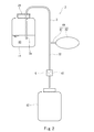
図1に、本発明の一実施形態に係る薬液ピペット装置2を示す。この薬液ピペット装置2は、細胞の培養に用いられる薬液10を第1容器11から第2容器12へ移送する際に用いられる。
図1に、本発明の一実施形態に係る薬液ピペット装置2を示す。この薬液ピペット装置2は、細胞の培養に用いられる薬液10を第1容器11から第2容器12へ移送する際に用いられる。
なお、第1容器11、第2容器12および薬液10の組合せの例示は、背景技術の欄で説明したとおりである。すなわち、第1容器11、第2容器12および薬液10の組合せは、以下の表1のいずれであってもよい。また、第1容器11および第2容器12の形状はどのような形状であってもよいし(例えば、薄いシャーレやフラスコなど)、第1容器11と第2容器12の一方または双方が薬液10が一ヶ所に集まるように傾けられてもよい。

第2容器12は、第1容器11よりも下方に位置する。ただし、第1容器11と第2容器12の水平方向の位置関係は、特に制限されるものではない。第1容器11と第2容器12の鉛直方向の位置関係については、必ずしも第2容器12の全体が鉛直方向において第1容器11の底よりも下方に位置している必要はない。
薬液ピペット装置2は、吸引口である上流端3aおよび排出口である下流端3bを有するサイフォン管3と、サイフォン管3に設けられた初期設定機構4Aを含む。さらに、サイフォン管3には、初期設定機構4Aよりも下流側に、サイフォン管3内の流路を開閉する開閉弁5が設けられている。
サイフォン管3は、上流端3aから下流端3bに向かって上向きから下向きに反転する形状を有している。上流端3aは、第1容器11内に挿入されて、第1容器11内の薬液10に浸される。下流端3bは、第2容器12内に挿入されてもよいし、第2容器12の上方に配置されてもよい。サイフォン管3内の流路の断面積は、薬液10の種類や粘性等により決定される。
本実施形態では、下流端3bに、硬質材料からなるノズル31が形成されており、サイフォン管3のその他の部分は、可撓性チューブ32で構成されている。ただし、サイフォン管3における後述するつまみ式の開閉弁5に対応する部分だけ可撓性チューブ32で構成され、サイフォン管3における可撓性チューブ32とノズル31の間の部分および可撓性チューブ32から上流端3aまでの部分は、硬質チューブで構成されてもよい。換言すれば、つまみ式の開閉弁5が採用される場合は、サイフォン管3は、少なくとも一部に可撓性チューブ32を含めばよい。あるいは、ノズル31が設けられずに、サイフォン管3の全体が可撓性チューブ32で構成されてもよい。さらには、つまみ式以外の開閉弁が採用される場合は、サイフォン管3の全体が硬質チューブで構成されてもよい。
さらに、本実施形態では、サイフォン管3における上流端3aから上向きに延びる部分に、第1容器11の開口形成部と係合するキャップ21が取り付けられている。この係合には、例えば、ネジ構造や嵌合を用いることができる。キャップ21は、第1容器11の開口を完全に閉塞しないように構成されている。例えば、キャップ21には、通気孔が設けられる。このように、キャップ21がサイフォン管3に取り付けられていれば、キャップ21を第1容器11の開口成形部に係合させるだけで、サイフォン管3の上流端3aを所望の位置に位置決めおよび維持することができる。ただし、薬液10を廃棄する場合などで上流端3aの位置を操作する場合には、キャップ21は省略可能である。
開閉弁5は、可撓性チューブ32をつまむ(pinch)ように構成されている。具体的に、開閉弁5は、可撓性チューブ32に沿う固定板51と、可撓性チューブ32を挟んで固定板51と反対側に配置されたつまみ部材52を含む。つまみ部材52は、図略のヒンジにより固定板51と連結されており、図略のバネにより固定板51に近づく方向又は固定板51から遠ざかる方向に付勢されている。
より詳しくは、つまみ部材52は、可撓性チューブ32を押し潰さない開位置と、固定板51上で可撓性チューブ32を完全に押し潰す閉位置との間で移動する。さらに、つまみ部材52は、開位置と閉位置の間の任意の位置で停止することができる。換言すれば、開閉弁5は、サイフォン管3内の流路を任意の開度に設定できるように構成されている。ただし、開閉弁5は、開位置と閉位置との間でのみ移動してもよい。
初期設定機構4Aは、サイフォン管3の上流端3aからサイフォン管3内に薬液10を導入するとともに、サイフォン管3内の薬液10を第1容器11内の薬液10の液面よりも下方の位置まで到達させるためのものである。具体的に、初期設定機構4Aは、サイフォン管3から分岐する分岐管41と、分岐管41に接続された操作体42を含む。
操作体42は、容積変化するものである。本実施形態では、操作体42として、卵形のゴムポンプであって圧縮されても自身の復元力で元の形状に戻るゴムポンプが採用されている。ただし、容積変化する操作体42は、例えばシリンジであってもよい。
操作体42は、分岐管41に対して着脱可能に構成されていることが望ましい。異なる薬液10に対しては、サイフォン管3および分岐管41を取り換える必要があるが、操作体42は薬液10に接していなければ継続して使用することができるからである。例えば、着脱可能な構造は、ネジ構造であってもよいし、圧入構造であってもよい。
次に、薬液ピペット装置2を使用する方法を説明する。なお、操作体42およびつまみ部材52の操作は、手動で行われてもよいし、電動アクチュエータなどを用いて行われてもよい。
まず、サイフォン管3の上流端3aを第1容器11内の薬液10に浸すとともに、サイフォン管3の下流端3bを第2容器12内に挿入するまたは第2容器12の上方に配置する(準備工程)。ついで、サイフォン管3内の流路を閉じるように開閉弁5のつまみ部材52を操作する。なお、このつまみ部材52の操作は、準備工程の前に行ってもよい。
その後、初期設定機構4Aを使用して、サイフォン管3の上流端3aからサイフォン管3内に薬液10を導入するとともに、サイフォン管3内の薬液10を第1容器11内の薬液10の液面よりも下方の位置まで到達させる(初期設定工程)。具体的には、まず、操作体42の容積を減少させて、吸引可能な状態を形成する。なお、この吸引可能な状態の形成は、準備工程の前に行ってもよい。ついで、操作体42の容積を徐々に元に戻す。これにより、サイフォン管3の上流端3aからサイフォン管3内に薬液10が導入される。
操作体42の容積を徐々に元に戻す間または元に戻した後に、サイフォン管3内の薬液10が第1容器11内の薬液10の液面よりも下方の位置まで到達すれば、サイフォン管3内の流路を開くように開閉弁5のつまみ部材52を操作する。これにより、サイフォン管3の下流端3bから第2容器12内に薬液10が流出する(移送工程)。
なお、初期設定工程における操作体42の容積の減少(吸引可能な状態の形成)は、サイフォン管3内の上流端3aから分岐管41の分岐点までの体積よりも僅かに少ない分だけ行われてもよい。このようにすれば、操作体42の容積を元に戻すだけで、サイフォン管3内の薬液10が第1容器11内の薬液10の液面よりも下方の位置まで到達した初期状態を実現することができる。
以上説明したように、本実施形態の薬液ピペット装置2では、サイフォンの原理により薬液10を移送できるので、一度に多量の薬液10を移送できる。しかも、薬液10はサイフォン管3の下流端3bから第2容器12内に流出するので、薬液10が飛び散って周辺を汚すことを防止できる。
また、本実施形態では開閉弁5が設けられているので、開閉弁5の操作により薬液10の移送量を制御することができる。しかも、開閉弁5によってサイフォン管3内の流路を閉じた状態で操作体42を操作すれば、サイフォン管3の上流端で薬液10の吸引と吐出を繰り返すことができる。従って、薬液ピペット装置2を使用して、第1容器11内で薬液10を攪拌することができる。このような撹拌は、例えば保管容器内での細胞と培地の混合に有用である。
さらに、開閉弁5が可撓性チューブ32をつまむように構成されているので、開閉弁5を、薬液10と非接触でかつ簡単な構成とすることができる。また、開閉弁5はサイフォン管3内の流路を任意の開度に設定できるので、薬液10の移送量を精密に制御することができる。
<変形例>
薬液ピペット装置2の構成は、前記実施形態で説明したとおりである必要はなく、種々の変形が可能である。
薬液ピペット装置2の構成は、前記実施形態で説明したとおりである必要はなく、種々の変形が可能である。
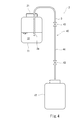
例えば、薬液10の移送量をそれほど厳密に制御する必要がない場合には、図2に示すように、開閉弁5の代わりに、揺動式の弁体61を含む逆止弁6が用いられてもよい。この構成であれば、操作体42の操作のみで薬液10の移送を開始することができる。薬液10の移送は、サイフォン管3の上流端3aを第1容器11内の薬液10中から取り出すことにより停止することができる。
また、サイフォン管3の脇に配置される初期設定機構4Aに代えて、図3に示すように、サイフォン管3に組み込まれた初期設定機構4Bを用いてもよい。この初期設定機構4Bは、一対の逆止弁6と、これらの逆止弁6の間に設けられた操作体42を含む。つまり、操作体42は、サイフォン管3の一部を構成する。
さらに、本発明の初期設定機構は、必ずしも容積変化する操作体42を含む必要はなく、図4に示すような初期設定機構4Cであってもよい。この初期設定機構4Cは、サイフォン管3の一部を構成する真空管44と、真空管44内の真空度を保つための一対の開閉弁43を含む。この構成でも、上流側の開閉弁43を開けば、第1容器11内の薬液10を上流端3aからサイフォン管3内に導入することができるとともに、サイフォン管3内の薬液10を第1容器11内の薬液10の液面よりも下方の位置まで到達させることができる。その後、下流側の開閉弁43を開けば、サイフォン管3の下流端3bから薬液10が流出する。なお、一対の開閉弁43のどちらか一方は、薬液10の移送量を制御する開閉弁として使用することができる。
ただし、図3および図4に示す初期設定機構4B,4Cを採用するよりも、図1および図2に示す分岐管41および操作体42を含む初期設定機構4Aを採用すれば、サイフォン管3を簡易かつコンパクトな構成としつつ、操作体42の容積によってサイフォン管3内への薬液10の導入量を十分に確保することができる。しかも、操作体42の容積に余裕があり、初期状態が達成されたときに操作体42の操作が途中であれば、サイフォン管3の上流端3aが薬液10から抜け出したときに、直ちに薬液10の吸引を開始して移送を継続することができる。
また、サイフォン管3および開閉弁5のセットを複数用いれば、それらの開閉弁5の開閉だけで、移送される薬液10の流量を制御することができる。
(薬液移送システム)
次に、図5を参照して、図1に示す薬液ピペット装置2を含む薬液移送システム7を説明する。この薬液移送システム7によれば、薬液10の移送を自動化することができる。
次に、図5を参照して、図1に示す薬液ピペット装置2を含む薬液移送システム7を説明する。この薬液移送システム7によれば、薬液10の移送を自動化することができる。
具体的に、薬液移送システム7は、サイフォン管3を支持するフレーム73と、フレーム73に固定された第1駆動機構71および第2駆動機構72と、第1駆動機構71および第2駆動機構72を制御する制御装置8を含む。また、薬液移送システム7は、第1容器11が載置される第1テーブル75と、第2容器12が載置される第2テーブル76を含む。本実施形態では、第2テーブル76上に、第2容器12の重量を計測する重量計91が配置されている。
第1駆動機構71は、初期設定機構4Aの操作体42を駆動し、第2駆動機構72は、開閉弁5のつまみ部材52を駆動する。制御装置8は、第1駆動機構71を介して初期設定機構4Aの操作体42を操作し、第2駆動機構72を介して開閉弁5のつまみ部材52を操作する。
制御装置8は、上述した重量計91と接続されているとともに、初期状態検出センサ92および操作パネル81と接続されている。初期状態検出センサ92は、サイフォン管3内の薬液10が第1容器11内の薬液10の液面よりも下方の位置まで到達した初期状態を検出するためのものであり、サイフォン管3における下流端3bに向かって下方に延びる部分の中間に位置するようにフレーム73に取り付けられている。初期状態検出センサ92は、サイフォン管3における分岐管41の分岐点よりも上流側に位置することが望ましい。分岐管41内にまで薬液が導入されることを防止するためである。操作パネル81は、使用者からの薬液10の移送の開始の入力を受け付ける。なお、制御装置8は、フレーム73に取り付けられて、制御装置8と外部通信機器(図示せず)との間で無線通信により各種の信号が伝達されてもよい。例えば、外部通信機器に操作パネル81が含まれ、移送開始信号が外部通信機器から制御装置8に送信されてもよい。
次に、制御装置8による初期設定機構4Aの操作体42および開閉弁5のつまみ部材52の操作を説明する。これらの操作が行われる前には、サイフォン管3の上流端3aが第1容器11内の薬液10に浸されるとともに、サイフォン管3の下流端3bが第2容器12内に挿入されるまたは第2容器12の上方に配置される。この準備作業は、フレーム73を鉛直方向に駆動する駆動機構を用いて自動的に行ってもよいし、手動で行ってもよい。
操作パネル81を通じて薬液10の移送の開始が入力されると、制御装置8は、サイフォン管3の上流端3aが第1容器11内の薬液10に浸されてから初期状態検出センサ92で初期状態が検出されるまでは、サイフォン管3内の流路を閉じるようにつまみ部材52を操作しつつ、サイフォン管3内に薬液10が導入されるように操作体42を操作する。操作体42の操作については、薬液ピペット装置2の使用方法で説明したとおりである。そして、初期状態検出センサ92により初期設態が検出されたときには、制御装置8は、操作体42の操作を停止するとともに、サイフォン管3内の流路を開くようにつまみ部材52を操作する。このように操作体42の操作を停止することによって、操作体42内に薬液10が吸引されることを防止できる。さらに、制御装置8は、重量計91で計測される重量の変化量が所定値となったときにサイフォン管3内の流路を閉じるようにつまみ部材52を操作する。これにより、薬液10を定量的に移送することができる。また、複数の第2容器12へ薬液10を定量ずつ供給することもできる。
つまみ式の開閉弁5は、第2駆動機構72に組み込まれていてもよい。このような構成であれば、サイフォン管3(図1では、可撓性チューブ32およびノズル31)および初期設定機構4Aのみを消耗品とすることができる。
<変形例>
重量計91は、第1テーブル75上に配置され、第1容器11の重量を計測してもよい。この構成でも、重量計91で計測される重量の変化量が所定値となったときに、サイフォン管3内の流路を閉じるようにつまみ部材52が操作される。
重量計91は、第1テーブル75上に配置され、第1容器11の重量を計測してもよい。この構成でも、重量計91で計測される重量の変化量が所定値となったときに、サイフォン管3内の流路を閉じるようにつまみ部材52が操作される。
また、第1容器11の重量を計測する重量計91は、サイフォン管3内に導入された薬液10の量を検出することも可能であるので、サイフォン管3内の薬液10が第1容器11内の薬液10の液面よりも下方の位置まで到達した初期状態を検出する初期状態検出センサとして使用することができる。この場合、図5に示すようなサイフォン管3の途中に設けられる初期状態検出センサ92は不要となる。
さらに、重量計91に代えて、図6に示すような第1容器11内の薬液10の液面を検出するレベル計93が用いられてもよい。このようなレベル計93を用いれば、液面の変化量によってサイフォン管3内に導入された薬液10の量を把握することができるため、図5に示すようなサイフォン管3の途中に設けられる初期状態検出センサ92は不要となる。換言すれば、レベル計93は、サイフォン管3内の薬液10が第1容器11内の薬液10の液面よりも下方の位置まで到達した初期状態を検出する初期状態検出センサとしても機能する。
さらには、第2駆動機構72を省略すれば、図1に示す薬液ピペット装置2の代わりに、図2または図3に示す薬液ピペット装置2を用いることができる。あるいは、第1駆動機構71を省略して、第2駆動機構72を2つ設ければ、図1に示す薬液ピペット装置2の代わりに、図4に示す薬液ピペット装置2を用いることができる。
(その他の実施形態)
本発明は上述した実施形態に限定されるものではなく、本発明の要旨を逸脱しない範囲で種々の変形が可能である。
本発明は上述した実施形態に限定されるものではなく、本発明の要旨を逸脱しない範囲で種々の変形が可能である。
10 薬液
11 第1容器
12 第2容器
2 薬液ピペット装置
21 キャップ
3 サイフォン管
3a 上流端
3b 下流端
32 可撓性チューブ
4A~4C 初期設定機構
41 分岐管
42 操作体
5 開閉弁
6 逆止弁
61 弁体
7 薬液移送システム
71 第1駆動機構
72 第2駆動機構
8 制御装置
91 重量計
92 初期状態検出センサ
93 レベル計(初期状態検出センサ)
11 第1容器
12 第2容器
2 薬液ピペット装置
21 キャップ
3 サイフォン管
3a 上流端
3b 下流端
32 可撓性チューブ
4A~4C 初期設定機構
41 分岐管
42 操作体
5 開閉弁
6 逆止弁
61 弁体
7 薬液移送システム
71 第1駆動機構
72 第2駆動機構
8 制御装置
91 重量計
92 初期状態検出センサ
93 レベル計(初期状態検出センサ)
Claims (18)
- 細胞の培養に用いられる薬液を第1容器から前記第1容器よりも下方に位置する第2容器へ移送する際に用いられるピペット装置であって、
前記第1容器内に挿入される上流端、および前記第2容器内に挿入されるまたは前記第2容器の上方に配置される下流端を有するサイフォン管と、
前記サイフォン管に設けられた、前記上流端から前記サイフォン管内に薬液を導入するとともに、前記サイフォン管内の薬液を前記第1容器内の薬液の液面よりも下方の位置まで到達させる初期設定機構と、
を備える、薬液ピペット装置。 - 前記初期設定機構は、前記サイフォン管から分岐する分岐管と、前記分岐管に接続された、容積変化する操作体を含む、請求項1に記載の薬液ピペット装置。
- 前記操作体は、前記分岐管に対して着脱可能に構成されている、請求項2に記載の薬液ピペット装置。
- 前記サイフォン管には、前記第1容器の開口形成部と係合するキャップが取り付けられている、請求項1~3のいずれか一項に記載の薬液ピペット装置。
- 前記初期設定機構よりも下流側で前記サイフォン管に設けられた、前記サイフォン管内の流路を開閉する開閉弁をさらに備える、請求項1~4のいずれか一項に記載の薬液ピペット装置。
- 前記サイフォン管は、少なくとも一部に可撓性チューブを含み、前記開閉弁は、前記可撓性チューブをつまむように構成されている、請求項5に記載の薬液ピペット装置。
- 前記開閉弁は、前記サイフォン管内の流路を任意の開度に設定できるように構成されている、請求項5または6に記載の薬液ピペット装置。
- 請求項5~7のいずれか一項に記載の薬液ピペット装置と、
前記初期設定機構を駆動する第1駆動機構と、
前記開閉弁を駆動する第2駆動機構と、
前記サイフォン管内の薬液が前記第1容器内の薬液の液面よりも下方の位置まで到達した初期状態を検出するための初期状態検出センサと、
前記第1駆動機構を介して前記初期設定機構を操作し、かつ、前記第2駆動機構を介して前記開閉弁を操作する制御装置と、を備え、
前記制御装置は、前記サイフォン管の上流端が前記第1容器内の薬液に浸されてから前記初期状態検出センサで前記初期状態が検出されるまでは、前記サイフォン管内の流路を閉じるように前記開閉弁を操作しつつ前記サイフォン管内に薬液が導入されるように前記初期設定機構を操作し、前記初期状態が検出されたときに前記初期設定機構の操作を停止するとともに前記サイフォン管内の流路を開くように前記開閉弁を操作する、薬液移送システム。 - 前記初期状態検出センサは、前記第1容器の重量を計測する重量計である、項請求項8に記載の薬液移送システム。
- 前記第2容器の重量を計測する重量計をさらに備える、項請求項8に記載の薬液移送システム。
- 前記制御装置は、前記重量計で計測される重量の変化量が所定値となったときに前記サイフォン管内の流路を閉じるように前記開閉弁を操作する、請求項9または10に記載の薬液移送システム。
- 細胞の培養に用いられる薬液を第1容器から前記第1容器よりも下方に位置する第2容器へ移送する方法であって、
サイフォン管の上流端を前記第1容器内の薬液に浸すとともに、前記サイフォン管の下流端を前記第2容器内に挿入するまたは前記第2容器の上方に配置する準備工程と、
前記サイフォン管の上流端から前記サイフォン管内に薬液を導入するとともに、前記サイフォン管内の薬液を前記第1容器内の薬液の液面よりも下方の位置まで到達させる初期設定工程と、
前記サイフォン管の下流端から前記第2容器内に薬液を流出させる移送工程と、
を備える、薬液移送方法。 - 前記サイフォン管には、前記第1容器の開口形成部と係合するキャップが取り付けられている、請求項12に記載の薬液移送方法。
- 前記初期設定工程では、前記サイフォン管に設けられた初期設定機構であって、前記サイフォン管から分岐する分岐管と、前記分岐管に接続された、容積変化する操作体と、を含む初期設定機構を使用する、請求項12または13に記載の薬液移送方法。
- 前記操作体は、前記分岐管に対して着脱可能に構成されている、請求項14に記載の薬液移送方法。
- 前記サイフォン管には、前記初期設定機構よりも下流側に、前記サイフォン管内の流路を開閉する開閉弁が設けられている、請求項14または15に記載の薬液移送方法。
- 前記サイフォン管は、少なくとも一部に可撓性チューブを含み、前記開閉弁は、前記可撓性チューブをつまむように構成されている、請求項16に記載の薬液移送方法。
- 前記開閉弁は、前記サイフォン管内の流路を任意の開度に設定できるように構成されている、請求項16または17に記載の薬液移送方法。
Applications Claiming Priority (2)
| Application Number | Priority Date | Filing Date | Title |
|---|---|---|---|
| JP2015066428A JP6564595B2 (ja) | 2015-03-27 | 2015-03-27 | 薬液ピペット装置、薬液移送システムおよび薬液移送方法 |
| JP2015-066428 | 2015-03-27 |
Publications (1)
| Publication Number | Publication Date |
|---|---|
| WO2016157865A1 true WO2016157865A1 (ja) | 2016-10-06 |
Family
ID=57005542
Family Applications (1)
| Application Number | Title | Priority Date | Filing Date |
|---|---|---|---|
| PCT/JP2016/001748 Ceased WO2016157865A1 (ja) | 2015-03-27 | 2016-03-25 | 薬液ピペット装置、薬液移送システムおよび薬液移送方法 |
Country Status (2)
| Country | Link |
|---|---|
| JP (1) | JP6564595B2 (ja) |
| WO (1) | WO2016157865A1 (ja) |
Cited By (1)
| Publication number | Priority date | Publication date | Assignee | Title |
|---|---|---|---|---|
| CN113218468A (zh) * | 2020-01-21 | 2021-08-06 | 弘塑科技股份有限公司 | 化学药剂定量装置及化学药剂定量方法 |
Families Citing this family (1)
| Publication number | Priority date | Publication date | Assignee | Title |
|---|---|---|---|---|
| JP7218188B2 (ja) * | 2019-01-25 | 2023-02-06 | 佐竹マルチミクス株式会社 | 培地交換装置 |
Citations (10)
| Publication number | Priority date | Publication date | Assignee | Title |
|---|---|---|---|---|
| JPS53144186A (en) * | 1977-04-20 | 1978-12-15 | Miles Lab | Inoculating instrument and method of using same |
| JPS5725597U (ja) * | 1980-07-18 | 1982-02-09 | ||
| JPH06165624A (ja) * | 1992-12-02 | 1994-06-14 | Iwate Pref Gov | 植物体の培養方法及びバイオリアクタ |
| JPH10191961A (ja) * | 1996-06-18 | 1998-07-28 | Ming-Yi Liau | 細胞の培養方法及び培養装置 |
| JP2002159241A (ja) * | 2000-11-27 | 2002-06-04 | Central Res Inst Of Electric Power Ind | 魚介類飼育装置 |
| JP2004089137A (ja) * | 2002-09-03 | 2004-03-25 | Olympus Corp | 培養装置および培地交換方法 |
| JP2011185254A (ja) * | 2010-03-10 | 2011-09-22 | Terumitsu Kawakazu | サイホン式ポンプ |
| JP2013013367A (ja) * | 2011-07-04 | 2013-01-24 | Nikon Corp | 培地供給装置、顕微鏡システム |
| WO2014077080A1 (ja) * | 2012-11-17 | 2014-05-22 | Yoshida Takashi | サイフォン管 |
| WO2016072460A1 (ja) * | 2014-11-06 | 2016-05-12 | オリンパス株式会社 | 細胞培養システムおよび細胞培養容器 |
-
2015
- 2015-03-27 JP JP2015066428A patent/JP6564595B2/ja active Active
-
2016
- 2016-03-25 WO PCT/JP2016/001748 patent/WO2016157865A1/ja not_active Ceased
Patent Citations (10)
| Publication number | Priority date | Publication date | Assignee | Title |
|---|---|---|---|---|
| JPS53144186A (en) * | 1977-04-20 | 1978-12-15 | Miles Lab | Inoculating instrument and method of using same |
| JPS5725597U (ja) * | 1980-07-18 | 1982-02-09 | ||
| JPH06165624A (ja) * | 1992-12-02 | 1994-06-14 | Iwate Pref Gov | 植物体の培養方法及びバイオリアクタ |
| JPH10191961A (ja) * | 1996-06-18 | 1998-07-28 | Ming-Yi Liau | 細胞の培養方法及び培養装置 |
| JP2002159241A (ja) * | 2000-11-27 | 2002-06-04 | Central Res Inst Of Electric Power Ind | 魚介類飼育装置 |
| JP2004089137A (ja) * | 2002-09-03 | 2004-03-25 | Olympus Corp | 培養装置および培地交換方法 |
| JP2011185254A (ja) * | 2010-03-10 | 2011-09-22 | Terumitsu Kawakazu | サイホン式ポンプ |
| JP2013013367A (ja) * | 2011-07-04 | 2013-01-24 | Nikon Corp | 培地供給装置、顕微鏡システム |
| WO2014077080A1 (ja) * | 2012-11-17 | 2014-05-22 | Yoshida Takashi | サイフォン管 |
| WO2016072460A1 (ja) * | 2014-11-06 | 2016-05-12 | オリンパス株式会社 | 細胞培養システムおよび細胞培養容器 |
Cited By (1)
| Publication number | Priority date | Publication date | Assignee | Title |
|---|---|---|---|---|
| CN113218468A (zh) * | 2020-01-21 | 2021-08-06 | 弘塑科技股份有限公司 | 化学药剂定量装置及化学药剂定量方法 |
Also Published As
| Publication number | Publication date |
|---|---|
| JP2016185089A (ja) | 2016-10-27 |
| JP6564595B2 (ja) | 2019-08-21 |
Similar Documents
| Publication | Publication Date | Title |
|---|---|---|
| JP6115667B2 (ja) | 分注装置 | |
| US10761000B2 (en) | Liquid stirring method | |
| CN105899954B (zh) | 分注装置以及分注方法 | |
| US20160332156A1 (en) | Soft stopper penetrating dispensing device and soft stopper penetrating dispensing method | |
| JP6564595B2 (ja) | 薬液ピペット装置、薬液移送システムおよび薬液移送方法 | |
| US20210239726A1 (en) | Reagent delivery and waste management system | |
| CN112051127B (zh) | 生物体液样本制备混匀装置及方法 | |
| JP2020156465A (ja) | 培養システム、培養装置、および多層培養容器操作装置 | |
| JP5866578B2 (ja) | 細胞培養装置および細胞培養方法 | |
| CN108780108B (zh) | 自动分析装置 | |
| CN204188404U (zh) | 一种固体样品定量自动取用装置 | |
| US9199237B2 (en) | Automated well plate | |
| WO2016009765A1 (ja) | 自動分析装置 | |
| CN105547763A (zh) | 双单向阀取样针及其取样方法 | |
| JP2011095058A (ja) | 生化学分析装置及び分注処理方法 | |
| JP2005172447A (ja) | 試料吸引分注装置およびそれを備えた標本作製装置 | |
| JP2010048738A (ja) | 分注装置および分注装置における目詰まり除去方法 | |
| JP2008048644A (ja) | 培養器具及び培養装置 | |
| JP4576340B2 (ja) | 自動分析装置 | |
| CN105388310B (zh) | 一种全自动粪便样本分析系统及分析方法 | |
| CN108675249B (zh) | 一种溶液连续快速分装工艺 | |
| WO2026078950A1 (ja) | 自動培養装置 | |
| JP5724810B2 (ja) | 液体排出機構及び分注装置 | |
| JP2010133838A (ja) | 反応処理装置 | |
| CN108713146A (zh) | 溶液排出装置及溶液的排出控制方法 |
Legal Events
| Date | Code | Title | Description |
|---|---|---|---|
| 121 | Ep: the epo has been informed by wipo that ep was designated in this application |
Ref document number: 16771753 Country of ref document: EP Kind code of ref document: A1 |
|
| NENP | Non-entry into the national phase |
Ref country code: DE |
|
| 122 | Ep: pct application non-entry in european phase |
Ref document number: 16771753 Country of ref document: EP Kind code of ref document: A1 |