WO2016157679A1 - 固縛用張力確認具 - Google Patents
固縛用張力確認具 Download PDFInfo
- Publication number
- WO2016157679A1 WO2016157679A1 PCT/JP2016/000590 JP2016000590W WO2016157679A1 WO 2016157679 A1 WO2016157679 A1 WO 2016157679A1 JP 2016000590 W JP2016000590 W JP 2016000590W WO 2016157679 A1 WO2016157679 A1 WO 2016157679A1
- Authority
- WO
- WIPO (PCT)
- Prior art keywords
- tension
- lashing
- pair
- belt
- band
- Prior art date
- Legal status (The legal status is an assumption and is not a legal conclusion. Google has not performed a legal analysis and makes no representation as to the accuracy of the status listed.)
- Ceased
Links
Images


Classifications
-
- G—PHYSICS
- G01—MEASURING; TESTING
- G01L—MEASURING FORCE, STRESS, TORQUE, WORK, MECHANICAL POWER, MECHANICAL EFFICIENCY, OR FLUID PRESSURE
- G01L5/00—Apparatus for, or methods of, measuring force, work, mechanical power, or torque, specially adapted for specific purposes
- G01L5/04—Apparatus for, or methods of, measuring force, work, mechanical power, or torque, specially adapted for specific purposes for measuring tension in flexible members, e.g. ropes, cables, wires, threads, belts or bands
- G01L5/06—Apparatus for, or methods of, measuring force, work, mechanical power, or torque, specially adapted for specific purposes for measuring tension in flexible members, e.g. ropes, cables, wires, threads, belts or bands using mechanical means
-
- B—PERFORMING OPERATIONS; TRANSPORTING
- B60—VEHICLES IN GENERAL
- B60P—VEHICLES ADAPTED FOR LOAD TRANSPORTATION OR TO TRANSPORT, TO CARRY, OR TO COMPRISE SPECIAL LOADS OR OBJECTS
- B60P7/00—Securing or covering of load on vehicles
- B60P7/06—Securing of load
- B60P7/08—Securing to the vehicle floor or sides
- B60P7/0823—Straps; Tighteners
- B60P7/0861—Measuring or identifying the tension in the securing element
-
- G—PHYSICS
- G01—MEASURING; TESTING
- G01L—MEASURING FORCE, STRESS, TORQUE, WORK, MECHANICAL POWER, MECHANICAL EFFICIENCY, OR FLUID PRESSURE
- G01L5/00—Apparatus for, or methods of, measuring force, work, mechanical power, or torque, specially adapted for specific purposes
- G01L5/04—Apparatus for, or methods of, measuring force, work, mechanical power, or torque, specially adapted for specific purposes for measuring tension in flexible members, e.g. ropes, cables, wires, threads, belts or bands
Definitions
- the present invention relates to a tension confirmation tool for lashing for confirming the tension of the band for lashing.
- a tension indicator for indicating the tension of the strap of the child safety seat of Patent Document 1 is known.
- the tension indicator rotates the rotating member against the biasing force of the spring member due to the tension of the strap so that the contact portion and the extending portion are aligned with each other. Is in a tension state.
- the belt tension detecting device of Patent Document 2 includes a belt bending mechanism that bends a belt under a certain tension and deforms according to the tension of the belt, and a sensor that detects the deformation of the mechanism.
- the belt bending mechanism has a flexible structure, and when the tension applied to the belt exceeds a certain limit, the belt is not bent but straight.
- the present invention has been made in view of the above points, and an object of the present invention is to make it possible to confirm whether or not a band for lashing is tightened with a simple structure and with a predetermined tension or higher. It is in.
- a part of the tension confirmation tool for lashing is broken when a predetermined tension or more is applied.
- the lashing tension checker is A pair of insertion portions that are arranged at a predetermined distance and each have a through-hole through which the banding body for lashing is inserted; A connecting part for connecting the pair of insertion parts; A tension detector provided in the connecting portion and provided at a position perpendicular to a straight line connecting the through holes of the pair of insertion portions so as to extend in the width direction of the tying band. ing.
- the tension detector is configured to break.
- the fragile portion may be provided in the tension detecting portion so as to be broken at a predetermined tension or more. According to this configuration, the tension setting at the time of breaking can be easily controlled by appropriately forming the fragile portion.
- the tension confirmation tool for lashing may be an integrally molded product of resin material. According to this configuration, a light and inexpensive tension confirmation tool for lashing can be obtained.
- the insertion part and the connection part are made of a resin molded product
- At least a portion of the tension detection unit that is broken may be formed of a metal member. According to this configuration, it is easier to control the breaking strength than the resin molded product by configuring the tension detection unit with the metal member.
- the present invention in a state where the band for lashing is inserted through the pair of insertion portions, one surface of the band for lashing is brought into contact with the tension detection unit, When a tension of a predetermined level or more is applied to the body, it is possible to confirm whether or not the banding body for lashing is tightened with a tension of a predetermined level or more with a simple structure by rupturing the tension detector.
- FIG. 2 is a sectional view taken along line II-II in FIG. It is a front view which expands and shows a tension
- FIG. 1 shows a lashing tension checker 1 according to an embodiment of the present invention.
- the lashing tension checker 1 is used to load a load by a lashing belt B as a lashing band, for example, a ship deck.
- a lashing belt B used to check the tension when fixing to
- the type of the tying belt B is not particularly limited, and may be a cloth belt such as polyester or a rubber belt containing a core wire.
- the tension of the lashing belt B is about 2 kN to 20 kN, the width is about 20 to 50 mm, and the thickness is about 2 mm to 3 mm.
- the lashing tension checker 1 is made of, for example, a resin molded product, and has a pair of insertion portions 2 arranged at a predetermined distance, and a lashing belt B is inserted into each insertion portion 2.
- a lashing belt B is inserted into each insertion portion 2.
- an oval through hole 2a is formed.
- the through-hole 2a only needs to have a width and a length through which the lashing belt B can be inserted.
- the width may be 5 mm and the length may be 60 mm.
- the cross section of the insertion part 2 is circular, it is not limited to this.
- the pair of insertion portions 2 are connected by a pair of rod-like connection portions 3 in the length direction of the lashing belt B.
- this connection part 3 is not specifically limited, In this embodiment, the cross section is circular.
- the tension detecting portion 4 extends in the width direction of the tying belt B at a position perpendicular to the straight line connecting the through holes 2a of the pair of insertion portions 2 vertically. (See FIG. 3) are provided integrally.
- the tension detecting unit 4 has, for example, a gate shape and a circular cross section when viewed from the longitudinal direction of the lashing belt B in order to increase the height at which the tying belt B is bent to some extent. It is formed integrally with the part 3.
- the tension detecting unit 4 is provided with notched weak portions 5 at intervals in the width direction of the lashing belt B so as to be broken at a predetermined tension or more.
- the fragile portion 5 may be a through hole or the like.
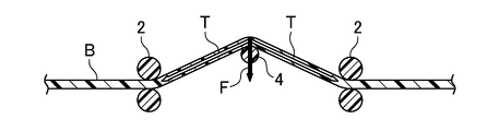
- the lashing belt B is inserted into the pair of insertion portions 2 as shown in FIG. At this time, the back surface (or the front surface) of the lashing belt B is brought into contact with the tension detection unit 4.
- a tightening machine (not shown) is attached to the tying belt B and gradually tightened. Then, as the belt tension T increases, the component force F applied to the tension detector 4 gradually increases. At this time, the lashing tension checking tool 1 is easy to work if it is immediately above the cargo tightening machine.
- the tension detection unit 4 When a tension T of a predetermined level or more is applied to the lashing belt B by the cargo tightening machine, the tension detection unit 4 is broken from the fragile part 5 by the component force F.
- the predetermined tension is set according to the size and weight of the conveyed product, the load applied during conveyance, and the like.
- the tension setting at the time of breakage can be easily controlled by appropriately forming the fragile portion 5 at an appropriate position.
- the tension confirmation tool 1 for lashing is formed of an integrally molded product of resin material, a light and inexpensive tension confirmation tool 1 for lashing can be obtained. Since it is inexpensive, a plurality of types of lashing tension checking tools 1 can be prepared for each predetermined tension. It is preferable that the proper use is facilitated by changing the color of the lashing tension checker 1 for each predetermined tension or changing the display.
- the lashing tension checking tool 1 it is possible to easily check whether the lashing belt B is fastened with a tension of a predetermined level or more with a simple structure.
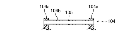
- FIG. 4 shows a modification of the embodiment of the present invention, which differs from the above embodiment in that the configuration of the tension detection unit 104 is different.
- the same parts as those in FIGS. 1 to 3 are denoted by the same reference numerals, and detailed description thereof is omitted.
- the insertion part 2 and the connecting part 3 are formed of a resin molded product, but the vertical part 104a extending vertically of the tension detecting part 104 is integrally formed with the connecting part 3 with a resin molded product. Yes.
- a round pipe-shaped fracture portion 104b connecting the pair of vertical portions 104a is formed of a metal member.
- the metal member is composed of a light metal round pipe such as an aluminum alloy.
- a fragile portion 105 made of a through hole is formed at the center in the longitudinal direction of the tension detecting portion 104.
- the fragile portion 105 may be a slit or may be provided at a plurality of locations.
- the fracture portion 104b of the tension detection unit 104 can be configured with a metal member with high finishing accuracy, so that the fracture strength can be controlled more easily than the resin molded product.
- the present invention may be configured as follows with respect to the above embodiment.
- the fragile portions 5 and 105 are provided, but even if the fragile portions 5 and 105 are not provided, the strength of the entire tension detection unit 4 is weakened so as to be broken at a tension equal to or higher than a predetermined tension. It may be.
- the tension detection unit 4 has a both-end supported structure in which both ends are supported, but may have a cantilever structure in which only one end is supported.
Landscapes
- Engineering & Computer Science (AREA)
- Transportation (AREA)
- Mechanical Engineering (AREA)
- Physics & Mathematics (AREA)
- General Physics & Mathematics (AREA)
- Force Measurement Appropriate To Specific Purposes (AREA)
- Clamps And Clips (AREA)
- Package Frames And Binding Bands (AREA)
- Measurement Of Current Or Voltage (AREA)
Abstract
Description
上記固縛用張力確認具は、
所定の距離を空けて配置され、上記固縛用帯状体が挿通される貫通孔をそれぞれ有する一対の挿通部と、
上記一対の挿通部を連結する連結部と、
上記連結部に設けられ、上記一対の挿通部の貫通孔を結ぶ直線から垂直に所定距離離れた位置に、上記固縛用帯状体の幅方向に延びるように設けられた張力検出部とを備えている。
上記張力検出部の少なくとも破断する部分は、金属部材で構成されていてもよい。この構成によると、張力検出部を金属部材で構成することで、樹脂成形品よりも破断強度を制御しやすい。
図4は本発明の実施形態の変形例を示し、張力検出部104の構成が異なる点で上記実施形態と異なる。なお、図1~図3と同じ部分については同じ符号を付してその詳細な説明は省略する。
本発明は、上記実施形態について、以下のような構成としてもよい。
2 挿通部
2a 貫通孔
3 連結部
4 張力検出部
5 脆弱部
104 張力検出部
104a 垂直部
104b 破断部
105 脆弱部
Claims (4)
- 固縛用帯状体の張力を確認する固縛用張力確認具において、
所定の距離を空けて配置され、上記固縛用帯状体が挿通される貫通孔をそれぞれ有する一対の挿通部と、
上記一対の挿通部を連結する連結部と、
上記連結部に設けられ、上記一対の挿通部の貫通孔を結ぶ直線から垂直に所定距離離れた位置に、上記固縛用帯状体の幅方向に延びるように設けられた張力検出部とを備え、
上記一対の挿通部に上記固縛用帯状体を挿通した状態で、該固縛用帯状体の一方の面が上記張力検出部に当接し、該固縛用帯状体に所定以上の張力を加えると、該張力検出部が破断するように構成されている
ことを特徴とする固縛用張力確認具。 - 請求項1に記載の固縛用張力確認具において、
上記張力検出部には、所定以上の張力で破断するように脆弱部が設けられている
ことを特徴とする固縛用張力確認具。 - 請求項1又は2に記載の固縛用張力確認具において、
樹脂材料の一体成形品よりなる
ことを特徴とする固縛用張力確認具。 - 請求項1又は2に記載の固縛用張力確認具において、
上記挿通部及び上記連結部は、樹脂成形品で構成され、
上記張力検出部の少なくとも破断する部分は、金属部材で構成されている
ことを特徴とする固縛用張力確認具。
Priority Applications (3)
| Application Number | Priority Date | Filing Date | Title |
|---|---|---|---|
| DE112016001527.5T DE112016001527T5 (de) | 2015-03-31 | 2016-02-05 | Spannungsverifikationswerkzeug zum Zurren |
| JP2017509192A JP6535731B2 (ja) | 2015-03-31 | 2016-02-05 | 固縛用張力確認具 |
| US15/687,453 US10288505B2 (en) | 2015-03-31 | 2017-08-26 | Lashing tension verification tool |
Applications Claiming Priority (2)
| Application Number | Priority Date | Filing Date | Title |
|---|---|---|---|
| JP2015070797 | 2015-03-31 | ||
| JP2015-070797 | 2015-03-31 |
Related Child Applications (1)
| Application Number | Title | Priority Date | Filing Date |
|---|---|---|---|
| US15/687,453 Continuation US10288505B2 (en) | 2015-03-31 | 2017-08-26 | Lashing tension verification tool |
Publications (1)
| Publication Number | Publication Date |
|---|---|
| WO2016157679A1 true WO2016157679A1 (ja) | 2016-10-06 |
Family
ID=57005888
Family Applications (1)
| Application Number | Title | Priority Date | Filing Date |
|---|---|---|---|
| PCT/JP2016/000590 Ceased WO2016157679A1 (ja) | 2015-03-31 | 2016-02-05 | 固縛用張力確認具 |
Country Status (4)
| Country | Link |
|---|---|
| US (1) | US10288505B2 (ja) |
| JP (1) | JP6535731B2 (ja) |
| DE (1) | DE112016001527T5 (ja) |
| WO (1) | WO2016157679A1 (ja) |
Cited By (4)
| Publication number | Priority date | Publication date | Assignee | Title |
|---|---|---|---|---|
| JP6227852B1 (ja) * | 2016-10-04 | 2017-11-08 | バンドー化学株式会社 | 固縛用張力確認具及びその製造方法 |
| CN109764997A (zh) * | 2017-11-10 | 2019-05-17 | 宝沃汽车(中国)有限公司 | 皮带张力检测方法及皮带张力计 |
| JP2019104601A (ja) * | 2017-12-13 | 2019-06-27 | グローブライド株式会社 | 電動巻き上げ装置及び該装置を備えた移動体 |
| CN110296782A (zh) * | 2019-06-28 | 2019-10-01 | 浙江双友物流器械股份有限公司 | 一种涨紧测力仪 |
Families Citing this family (2)
| Publication number | Priority date | Publication date | Assignee | Title |
|---|---|---|---|---|
| US12077091B2 (en) | 2020-10-08 | 2024-09-03 | J.J. Keller & Associates, Inc. | Method and apparatus for setting, monitoring, usage tracking and/or lifecycle management of cargo restraints |
| CA3098709C (en) | 2020-11-10 | 2024-10-08 | Intelligent Secure Strap Inc. | BELT TENSION DETECTION |
Citations (5)
| Publication number | Priority date | Publication date | Assignee | Title |
|---|---|---|---|---|
| JPS63159740U (ja) * | 1987-04-07 | 1988-10-19 | ||
| US4992778A (en) * | 1989-12-22 | 1991-02-12 | The University Of New Mexico | Pre-failure tension warning device |
| US5400868A (en) * | 1993-10-04 | 1995-03-28 | Research And Trading Corporation | Shock indicator for use on safety cables |
| US20010035122A1 (en) * | 2000-04-04 | 2001-11-01 | Wayne Margetts | Tension overload indicator |
| JP2012112152A (ja) * | 2010-11-24 | 2012-06-14 | Takenaka Komuten Co Ltd | 構造体支承装置、構造物及び構造物の建替え方法 |
Family Cites Families (30)
| Publication number | Priority date | Publication date | Assignee | Title |
|---|---|---|---|---|
| US3329013A (en) * | 1963-09-11 | 1967-07-04 | Dayco Corp | Tension measuring device |
| US3296857A (en) * | 1964-08-19 | 1967-01-10 | Huyck Corp | Apparatus for measuring the tension of flexible materials |
| US3832899A (en) * | 1972-02-17 | 1974-09-03 | Inst Cercetare Ind Extractiva | Dynamometrical deflection measuring method and apparatus |
| US3879999A (en) * | 1973-05-02 | 1975-04-29 | Erwin J Saxl | Tension meters |
| US3994162A (en) * | 1975-10-02 | 1976-11-30 | David William Auckland | Yarn tension measuring |
| US4135393A (en) * | 1978-02-14 | 1979-01-23 | Jordan Donald J | Tensiometer |
| DE3138655C2 (de) * | 1981-09-29 | 1983-10-27 | Spanset Inter AG, 4002 Basel | Vorrichtung zum Messen der Zugspannung von Zurrmitteln |
| US4506555A (en) * | 1983-10-07 | 1985-03-26 | Baker Drilling Equipment Company | Cable tension measuring device |
| US5026230A (en) * | 1987-04-18 | 1991-06-25 | Udo Dolezych | Load lashing device with tensioner for use on a freight carrier |
| SE9102218L (sv) * | 1991-07-22 | 1992-06-22 | Volvo Ab | Anordning foer indikering av en foerutbestaemd foerspaenningskraft i laangstraeckta, flexibla element |
| US5361959A (en) * | 1991-12-02 | 1994-11-08 | Allen Alexander R | Strap tensioning system |
| US5965827A (en) * | 1997-05-12 | 1999-10-12 | Automotive Systems Laboratory, Inc. | Seat belt tension measurement device using a bend sensor |
| US6357978B1 (en) * | 1997-06-03 | 2002-03-19 | Spanset Inter Ag | Load indicator on traction elements |
| US5845370A (en) * | 1997-06-17 | 1998-12-08 | Cohoon; Gilbert | Self-positioning tie down strap |
| US6041666A (en) * | 1998-01-08 | 2000-03-28 | Mackarvich; Charles J. | Strap tension measurement device |
| JP2001180441A (ja) | 1999-10-29 | 2001-07-03 | Takata Corp | ベルト張力検出装置 |
| US6623032B2 (en) * | 2000-01-24 | 2003-09-23 | Siemens Vdo Automotive Corporation | Belt force sensor |
| KR20030043791A (ko) * | 2000-05-12 | 2003-06-02 | 지멘스 비디오 오토모티브 코포레이션 | 시트벨트력 센서 시스템 |
| US6520032B2 (en) * | 2001-03-27 | 2003-02-18 | Trw Vehicle Safety Systems Inc. | Seat belt tension sensing apparatus |
| US6851715B2 (en) * | 2002-03-12 | 2005-02-08 | Trw Vehicle Safety Systems Inc. | Apparatus for measuring tension in seat belt webbing |
| WO2004005074A2 (en) * | 2002-07-10 | 2004-01-15 | Automotive Systems Laboratory, Inc. | Method of attaching a seat belt to a seat belt tension sensor |
| US7242286B2 (en) * | 2003-08-22 | 2007-07-10 | Autoliv Asp, Inc. | Seat belt tension indicator |
| GB0410185D0 (en) | 2004-05-07 | 2004-06-09 | Britax Excelsior | Tension indicator |
| SE0500578L (sv) * | 2005-03-14 | 2006-09-05 | Lindual Ab | Anordning vid godssurrning |
| GB0519472D0 (en) * | 2005-09-23 | 2005-11-02 | Shams Iden | Device |
| EP2025256A1 (en) * | 2007-08-03 | 2009-02-18 | SABELT S.p.A. | A tension regulator for a safety belt of a seat, in particular a child safety seat |
| GB2466463A (en) * | 2008-12-22 | 2010-06-23 | Express Hire | Low strap tension warning device for securing loads on vehicles |
| DE102010014167A1 (de) * | 2010-03-19 | 2011-12-15 | Polycontact Ag | Gurtspannungsüberwachung |
| SE535527C2 (sv) * | 2010-04-15 | 2012-09-11 | Tenmet Ab | Anordning för kontroll av spänning i band |
| CH710461A1 (de) * | 2014-12-11 | 2016-06-15 | Spanset Inter Ag | Vorrichtung und Verfahren zur Messung der Zugspannung in einem Spanngurt. |
-
2016
- 2016-02-05 DE DE112016001527.5T patent/DE112016001527T5/de not_active Withdrawn
- 2016-02-05 JP JP2017509192A patent/JP6535731B2/ja not_active Expired - Fee Related
- 2016-02-05 WO PCT/JP2016/000590 patent/WO2016157679A1/ja not_active Ceased
-
2017
- 2017-08-26 US US15/687,453 patent/US10288505B2/en active Active
Patent Citations (5)
| Publication number | Priority date | Publication date | Assignee | Title |
|---|---|---|---|---|
| JPS63159740U (ja) * | 1987-04-07 | 1988-10-19 | ||
| US4992778A (en) * | 1989-12-22 | 1991-02-12 | The University Of New Mexico | Pre-failure tension warning device |
| US5400868A (en) * | 1993-10-04 | 1995-03-28 | Research And Trading Corporation | Shock indicator for use on safety cables |
| US20010035122A1 (en) * | 2000-04-04 | 2001-11-01 | Wayne Margetts | Tension overload indicator |
| JP2012112152A (ja) * | 2010-11-24 | 2012-06-14 | Takenaka Komuten Co Ltd | 構造体支承装置、構造物及び構造物の建替え方法 |
Cited By (4)
| Publication number | Priority date | Publication date | Assignee | Title |
|---|---|---|---|---|
| JP6227852B1 (ja) * | 2016-10-04 | 2017-11-08 | バンドー化学株式会社 | 固縛用張力確認具及びその製造方法 |
| CN109764997A (zh) * | 2017-11-10 | 2019-05-17 | 宝沃汽车(中国)有限公司 | 皮带张力检测方法及皮带张力计 |
| JP2019104601A (ja) * | 2017-12-13 | 2019-06-27 | グローブライド株式会社 | 電動巻き上げ装置及び該装置を備えた移動体 |
| CN110296782A (zh) * | 2019-06-28 | 2019-10-01 | 浙江双友物流器械股份有限公司 | 一种涨紧测力仪 |
Also Published As
| Publication number | Publication date |
|---|---|
| DE112016001527T5 (de) | 2018-01-04 |
| JPWO2016157679A1 (ja) | 2018-02-01 |
| JP6535731B2 (ja) | 2019-06-26 |
| US20170356819A1 (en) | 2017-12-14 |
| US10288505B2 (en) | 2019-05-14 |
Similar Documents
| Publication | Publication Date | Title |
|---|---|---|
| JP6535731B2 (ja) | 固縛用張力確認具 | |
| US4457251A (en) | Belt load indicator | |
| WO2007115301A3 (en) | Harness tension sensor and crash occurrence sensor | |
| US9592754B2 (en) | Vehicle rear seat cushion structure | |
| AU736367B2 (en) | Load indicators on traction elements | |
| US3154026A (en) | Articulated tie-down load control bracket | |
| KR20190063901A (ko) | 고박용 장력 측정 장치 | |
| CN101163610B (zh) | 加载捆扎装置 | |
| CN101310640B (zh) | 固定货物的带扣 | |
| US9682845B2 (en) | Rope load detecting device for detecting the total rope load in multiple elevator ropes | |
| US11970124B2 (en) | Occupancy sensor for wheeled mobility device restraint | |
| KR20160006455A (ko) | 자동차용 시트 벨트 버클 이송 장치 | |
| JP6032154B2 (ja) | エレベータの釣合い重り | |
| JP6227852B1 (ja) | 固縛用張力確認具及びその製造方法 | |
| JP5169673B2 (ja) | 乗員拘束具 | |
| JP2017119457A (ja) | ロッキングタング | |
| JP6991655B2 (ja) | ハーネス配索構造 | |
| CN104528600B (zh) | 链条松动检测装置、臂架以及消防车 | |
| JP6509134B2 (ja) | ウェイトチェッカー | |
| KR200439949Y1 (ko) | 벨트 안전 보완장치 | |
| JP2009209951A (ja) | パイプホイップレストレイント | |
| JP3182549U (ja) | ラケットに2本のセンターメインストリングを張る際に、スタータクランプとヘッドバンパー又はフレームのグロメットとの間に配置するアダプター | |
| CN101213119A (zh) | 舌片板止动器以及使用该舌片板止动器的安全带装置 | |
| CN120135107A (zh) | 安全带固定验证系统 | |
| JP4759611B2 (ja) | シートベルトのロッキングクリップ |
Legal Events
| Date | Code | Title | Description |
|---|---|---|---|
| 121 | Ep: the epo has been informed by wipo that ep was designated in this application |
Ref document number: 16771576 Country of ref document: EP Kind code of ref document: A1 |
|
| ENP | Entry into the national phase |
Ref document number: 2017509192 Country of ref document: JP Kind code of ref document: A |
|
| WWE | Wipo information: entry into national phase |
Ref document number: 112016001527 Country of ref document: DE |
|
| 122 | Ep: pct application non-entry in european phase |
Ref document number: 16771576 Country of ref document: EP Kind code of ref document: A1 |