WO2016157646A1 - 急速撹拌機の制御方法および急速撹拌機 - Google Patents
急速撹拌機の制御方法および急速撹拌機 Download PDFInfo
- Publication number
- WO2016157646A1 WO2016157646A1 PCT/JP2015/085529 JP2015085529W WO2016157646A1 WO 2016157646 A1 WO2016157646 A1 WO 2016157646A1 JP 2015085529 W JP2015085529 W JP 2015085529W WO 2016157646 A1 WO2016157646 A1 WO 2016157646A1
- Authority
- WO
- WIPO (PCT)
- Prior art keywords
- sludge
- rapid
- flocculant
- stirrer
- stirring
- Prior art date
- Legal status (The legal status is an assumption and is not a legal conclusion. Google has not performed a legal analysis and makes no representation as to the accuracy of the status listed.)
- Ceased
Links
Images


Classifications
-
- C—CHEMISTRY; METALLURGY
- C02—TREATMENT OF WATER, WASTE WATER, SEWAGE, OR SLUDGE
- C02F—TREATMENT OF WATER, WASTE WATER, SEWAGE, OR SLUDGE
- C02F1/00—Treatment of water, waste water, or sewage
- C02F1/52—Treatment of water, waste water, or sewage by flocculation or precipitation of suspended impurities
- C02F1/5209—Regulation methods for flocculation or precipitation
-
- B—PERFORMING OPERATIONS; TRANSPORTING
- B01—PHYSICAL OR CHEMICAL PROCESSES OR APPARATUS IN GENERAL
- B01D—SEPARATION
- B01D21/00—Separation of suspended solid particles from liquids by sedimentation
- B01D21/01—Separation of suspended solid particles from liquids by sedimentation using flocculating agents
-
- B—PERFORMING OPERATIONS; TRANSPORTING
- B01—PHYSICAL OR CHEMICAL PROCESSES OR APPARATUS IN GENERAL
- B01D—SEPARATION
- B01D21/00—Separation of suspended solid particles from liquids by sedimentation
- B01D21/30—Control equipment
-
- B—PERFORMING OPERATIONS; TRANSPORTING
- B01—PHYSICAL OR CHEMICAL PROCESSES OR APPARATUS IN GENERAL
- B01F—MIXING, e.g. DISSOLVING, EMULSIFYING OR DISPERSING
- B01F23/00—Mixing according to the phases to be mixed, e.g. dispersing or emulsifying
- B01F23/50—Mixing liquids with solids
- B01F23/53—Mixing liquids with solids using driven stirrers
-
- B—PERFORMING OPERATIONS; TRANSPORTING
- B01—PHYSICAL OR CHEMICAL PROCESSES OR APPARATUS IN GENERAL
- B01F—MIXING, e.g. DISSOLVING, EMULSIFYING OR DISPERSING
- B01F27/00—Mixers with rotary stirring devices in fixed receptacles; Kneaders
- B01F27/05—Stirrers
- B01F27/11—Stirrers characterised by the configuration of the stirrers
- B01F27/111—Centrifugal stirrers, i.e. stirrers with radial outlets; Stirrers of the turbine type, e.g. with means to guide the flow
- B01F27/1111—Centrifugal stirrers, i.e. stirrers with radial outlets; Stirrers of the turbine type, e.g. with means to guide the flow with a flat disc or with a disc-like element equipped with blades, e.g. Rushton turbine
-
- B—PERFORMING OPERATIONS; TRANSPORTING
- B01—PHYSICAL OR CHEMICAL PROCESSES OR APPARATUS IN GENERAL
- B01F—MIXING, e.g. DISSOLVING, EMULSIFYING OR DISPERSING
- B01F27/00—Mixers with rotary stirring devices in fixed receptacles; Kneaders
- B01F27/80—Mixers with rotary stirring devices in fixed receptacles; Kneaders with stirrers rotating about a substantially vertical axis
- B01F27/84—Mixers with rotary stirring devices in fixed receptacles; Kneaders with stirrers rotating about a substantially vertical axis with two or more stirrers rotating at different speeds or in opposite directions about the same axis
-
- B—PERFORMING OPERATIONS; TRANSPORTING
- B01—PHYSICAL OR CHEMICAL PROCESSES OR APPARATUS IN GENERAL
- B01F—MIXING, e.g. DISSOLVING, EMULSIFYING OR DISPERSING
- B01F27/00—Mixers with rotary stirring devices in fixed receptacles; Kneaders
- B01F27/80—Mixers with rotary stirring devices in fixed receptacles; Kneaders with stirrers rotating about a substantially vertical axis
- B01F27/87—Mixers with rotary stirring devices in fixed receptacles; Kneaders with stirrers rotating about a substantially vertical axis the receptacle being divided into superimposed compartments
-
- B—PERFORMING OPERATIONS; TRANSPORTING
- B01—PHYSICAL OR CHEMICAL PROCESSES OR APPARATUS IN GENERAL
- B01F—MIXING, e.g. DISSOLVING, EMULSIFYING OR DISPERSING
- B01F27/00—Mixers with rotary stirring devices in fixed receptacles; Kneaders
- B01F27/80—Mixers with rotary stirring devices in fixed receptacles; Kneaders with stirrers rotating about a substantially vertical axis
- B01F27/90—Mixers with rotary stirring devices in fixed receptacles; Kneaders with stirrers rotating about a substantially vertical axis with paddles or arms
-
- B—PERFORMING OPERATIONS; TRANSPORTING
- B01—PHYSICAL OR CHEMICAL PROCESSES OR APPARATUS IN GENERAL
- B01F—MIXING, e.g. DISSOLVING, EMULSIFYING OR DISPERSING
- B01F27/00—Mixers with rotary stirring devices in fixed receptacles; Kneaders
- B01F27/80—Mixers with rotary stirring devices in fixed receptacles; Kneaders with stirrers rotating about a substantially vertical axis
- B01F27/91—Mixers with rotary stirring devices in fixed receptacles; Kneaders with stirrers rotating about a substantially vertical axis with propellers
-
- B—PERFORMING OPERATIONS; TRANSPORTING
- B01—PHYSICAL OR CHEMICAL PROCESSES OR APPARATUS IN GENERAL
- B01F—MIXING, e.g. DISSOLVING, EMULSIFYING OR DISPERSING
- B01F35/00—Accessories for mixers; Auxiliary operations or auxiliary devices; Parts or details of general application
- B01F35/20—Measuring; Control or regulation
- B01F35/21—Measuring
- B01F35/211—Measuring of the operational parameters
- B01F35/2111—Flow rate
- B01F35/21112—Volumetric flow rate
-
- B—PERFORMING OPERATIONS; TRANSPORTING
- B01—PHYSICAL OR CHEMICAL PROCESSES OR APPARATUS IN GENERAL
- B01F—MIXING, e.g. DISSOLVING, EMULSIFYING OR DISPERSING
- B01F35/00—Accessories for mixers; Auxiliary operations or auxiliary devices; Parts or details of general application
- B01F35/20—Measuring; Control or regulation
- B01F35/21—Measuring
- B01F35/212—Measuring of the driving system data, e.g. torque, speed or power data
-
- B—PERFORMING OPERATIONS; TRANSPORTING
- B01—PHYSICAL OR CHEMICAL PROCESSES OR APPARATUS IN GENERAL
- B01F—MIXING, e.g. DISSOLVING, EMULSIFYING OR DISPERSING
- B01F35/00—Accessories for mixers; Auxiliary operations or auxiliary devices; Parts or details of general application
- B01F35/20—Measuring; Control or regulation
- B01F35/22—Control or regulation
- B01F35/221—Control or regulation of operational parameters, e.g. level of material in the mixer, temperature or pressure
- B01F35/2214—Speed during the operation
- B01F35/22142—Speed of the mixing device during the operation
- B01F35/221422—Speed of rotation of the mixing axis, stirrer or receptacle during the operation
-
- B—PERFORMING OPERATIONS; TRANSPORTING
- B01—PHYSICAL OR CHEMICAL PROCESSES OR APPARATUS IN GENERAL
- B01F—MIXING, e.g. DISSOLVING, EMULSIFYING OR DISPERSING
- B01F35/00—Accessories for mixers; Auxiliary operations or auxiliary devices; Parts or details of general application
- B01F35/71—Feed mechanisms
- B01F35/717—Feed mechanisms characterised by the means for feeding the components to the mixer
- B01F35/7176—Feed mechanisms characterised by the means for feeding the components to the mixer using pumps
-
- C—CHEMISTRY; METALLURGY
- C02—TREATMENT OF WATER, WASTE WATER, SEWAGE, OR SLUDGE
- C02F—TREATMENT OF WATER, WASTE WATER, SEWAGE, OR SLUDGE
- C02F11/00—Treatment of sludge; Devices therefor
- C02F11/12—Treatment of sludge; Devices therefor by de-watering, drying or thickening
- C02F11/14—Treatment of sludge; Devices therefor by de-watering, drying or thickening with addition of chemical agents
- C02F11/147—Treatment of sludge; Devices therefor by de-watering, drying or thickening with addition of chemical agents using organic substances
-
- B—PERFORMING OPERATIONS; TRANSPORTING
- B01—PHYSICAL OR CHEMICAL PROCESSES OR APPARATUS IN GENERAL
- B01F—MIXING, e.g. DISSOLVING, EMULSIFYING OR DISPERSING
- B01F2101/00—Mixing characterised by the nature of the mixed materials or by the application field
- B01F2101/305—Treatment of water, waste water or sewage
-
- B—PERFORMING OPERATIONS; TRANSPORTING
- B01—PHYSICAL OR CHEMICAL PROCESSES OR APPARATUS IN GENERAL
- B01F—MIXING, e.g. DISSOLVING, EMULSIFYING OR DISPERSING
- B01F2215/00—Auxiliary or complementary information in relation with mixing
- B01F2215/04—Technical information in relation with mixing
- B01F2215/0413—Numerical information
- B01F2215/0418—Geometrical information
- B01F2215/0431—Numerical size values, e.g. diameter of a hole or conduit, area, volume, length, width, or ratios thereof
-
- C—CHEMISTRY; METALLURGY
- C02—TREATMENT OF WATER, WASTE WATER, SEWAGE, OR SLUDGE
- C02F—TREATMENT OF WATER, WASTE WATER, SEWAGE, OR SLUDGE
- C02F2209/00—Controlling or monitoring parameters in water treatment
- C02F2209/40—Liquid flow rate
Definitions
- the present invention relates to a technique for controlling a rapid stirrer of an agglomeration mixing tank used in a water treatment facility or the like.
- Patent Document 1 describes a technique of photographing the floc state of a floc in a stock solution and adjusting the amount of flocculant added and the rotational speed of the flocculant stirrer.
- This includes an imaging unit that captures the aggregated floc, a luminance signal of the aggregated floc image, which is converted into an electrical signal, the image is binarized from the electrical signal, and a binary image is generated, and the binary image is displayed.
- a calculation unit that calculates the aggregated floc area, a comparison unit that compares the aggregated floc measurement area and the aggregated floc reference area, and controls the rotation speed of the coagulant supply pump and the coagulant stirrer according to the comparison result
- a control unit and an output unit that issues an alarm according to the comparison result and the calculation unit calculates an aggregation floc area for a plurality of times at the same coagulant addition rate in advance, and an average value of the aggregation floc areas for a plurality of times
- the average aggregated floc area is calculated, and the aggregated floc reference area is calculated based on the average aggregated floc area.
- the flocculant addition rate to be added to the sludge supplied to the flocculation mixing tank is controlled, and the rotation speed of the flocculant stirrer that performs slow stirring is controlled is doing.
- Patent Document 2 describes a technique for automatically determining the state of sludge aggregation. This includes the step of injecting a predetermined amount of flocculant into sludge, the step of photographing an image of the state of coagulation of sludge, the step of compressing the digital image data of the coagulated state of the sludge taken, and the compressed digital A step of comparing the image data amount with a predetermined threshold value, and in the comparison step, when the compressed digital image data amount is less than the predetermined threshold value, the injection amount of the flocculant is increased or decreased.
- Sludge is continuously sent to the coagulation and mixing tank and is continuously supplied from the coagulation and mixing tank to a dehydrator or a concentrator.
- the amount of sludge input changes according to the progress of processing in the dehydrator. If the progress of the dehydrator processing is fast, the amount of sludge input to the coagulation mixing tank per unit time will increase, reducing the time for sludge to stay in the coagulation mixing tank, and the amount of sludge input to the coagulation mixing tank will be reduced. By decreasing, the time during which sludge stays in the coagulation mixing tank increases.
- the flocculant is dispersed in the water to be treated to produce agglomerated floc-forming nuclei as nuclei for forming agglomerated flocs, and turbidity in the water to be treated is aggregated around the agglomerated floc-forming nuclei. Forms fine flocs.
- Slow stirring agglomerates fine flocs and sludge.
- the present invention solves the above-mentioned problems, and a rapid stirrer that can contribute to the stability of dewatering performance by appropriately controlling the rotation speed of the stirring blade in rapid stirring according to the increase or decrease of the sludge input amount and the flocculant input amount
- An object of the present invention is to provide a control method and a rapid stirrer.
- the rapid stirrer control method of the present invention is a rapid stirrer that stirs sludge and aggregating agent with stirring blades in a tank, according to an increase in the amount of sludge input or the amount of solid matter. Increase the number of revolutions of the stirring blades at the set ratio, and decrease the number of revolutions of the stirring blades at the set ratio according to the decrease in the amount of sludge input, so that the floc diameter remains constant even when the operating conditions change.
- the agglomerate floc is stably generated.
- the control method of the rapid stirrer of the present invention is a rapid stirrer that stirs sludge and flocculant with stirring blades in the tank, and increases the rotation speed of the stirring blades at a set ratio according to the increase of the flocculant input amount, The rotating speed of the agitating blade is decreased by a set ratio according to the decrease in the flocculant input amount, and stable floc flocs with a constant floc diameter can be generated even when the operating conditions change when the sludge input amount increases or decreases.
- the rapid stirrer of the present invention includes a rapid stirring tank body for stirring sludge and a flocculant, a stirrer having a stirring blade rotating around the axis of a drive shaft disposed inside the rapid stirring tank body, It is equipped with a sludge supply system that supplies sludge to the agitation tank body, a flocculant supply system that introduces a flocculant into the sludge that is supplied to the rapid agitation tank body, and an agitator control device that controls the rotation speed of the agitator.
- the control unit increases the rotation speed of the stirring blades at a set ratio according to the increase of the sludge input amount or solid matter by the sludge supply system, and the rotation speed of the stirring blades according to the decrease of the sludge input amount by the sludge supply system. Is reduced by a set ratio.
- the rapid stirrer of the present invention includes a rapid stirring tank body for stirring sludge and a flocculant, a stirrer having a stirring blade rotating around the axis of a drive shaft disposed inside the rapid stirring tank body, It is equipped with a sludge supply system that supplies sludge to the agitation tank body, a flocculant supply system that introduces a flocculant into the sludge that is supplied to the rapid agitation tank body, and an agitator control device that controls the rotation speed of the agitator.
- the control device increases the rotation speed of the stirring blade at a set ratio according to the increase in the flocculant input amount by the flocculant supply system, and increases the rotation speed of the stirring blade according to the decrease in the flocculant input amount by the flocculant supply system. It is reduced by a set ratio.
- the sludge supply system and the flocculant supply system are provided with a pump and a flow meter, and the stirrer control device determines the rotational speed of the stirring blade by using the flow rate measured by the flow meter or the rotational speed of the pump as an index. It is characterized by controlling.
- a flocculent mixing device is formed by any of the above-mentioned rapid stirrers and a slow stirrer communicating with the rapid stirrer, and a dehydrator is disposed in a subsequent process of the flocculent mixing device. It is characterized by.
- a flocculent mixing device is formed by any one of the above rapid stirrers and a slow stirrer communicating with the rapid stirrer, and a concentrator is disposed in a subsequent process of the flocculent mixing device. It is characterized by.
- the flocculant and the sludge are retained in the tank by increasing or decreasing the rotational speed of the stirring blade at a set ratio according to the increase or decrease of the sludge input amount or the increase or decrease of the flocculant input amount.
- the contact frequency between the solid fine particles in the sludge and the agglomerated floc-forming nuclei within time is ensured appropriately and sufficiently.
- agglomerated flocs having a constant floc diameter can be stably generated even when the operating conditions change when the sludge input amount increases or decreases.
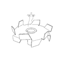
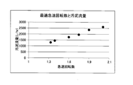
- the schematic diagram which shows the sludge treatment system in embodiment of this invention The perspective view which shows the edged turbine blade in the rapid stirrer of the aggregation mixing apparatus in the same embodiment Graph showing the relationship between rapid rotation speed and sludge input Graph showing the relationship between the rapid rotation speed and the chemical flow rate that is the amount of flocculant charged
- the agglomeration and mixing apparatus 100 includes a rapid stirrer 10 and a slow stirrer 50, and the slow stirrer 50 is disposed above the rapid stirrer 10, and the tank body of the rapid stirrer 10.
- the ceiling 11 and the tank bottom 51 of the slow agitator 50 communicate with each other at the opening 12.
- the rapid stirrer 10 has a rapid stirring tank body 13 for stirring sludge and a flocculant.
- the sludge is a slurry-like substance such as sewage sludge
- the flocculant is a polymer flocculant or the like.
- the rapid stirring tank body 13 is connected to one side of the side wall by a sludge supply system 14 for supplying sludge, and a flocculant supply system 15 for supplying a flocculant in the middle of the sludge supply system 14 is connected. .
- the sludge supply system 14 includes a sludge storage tank 141, a sludge supply pump 142, a sludge flow meter 143, and a sludge concentration meter 144 sequentially from the upstream side to the downstream side.
- the coagulant supply system 15 includes a polymer coagulant dissolution tank 151, a coagulant supply pump 152, and a coagulant flow meter 153 in order from the upstream side to the downstream side, and controls the operation of the coagulant supply pump 152.
- a flocculant flow rate control device 154 is provided.
- the flocculant flow control device 154 increases or decreases the rotation speed of the flocculant supply pump 152 using the measured values of the sludge flow meter 143, the sludge concentration meter 144, and the flocculant flow meter 153 as indexes.
- a drive shaft 16 is arranged vertically along the tank body axis, and an edged turbine blade 17 is attached to the drive shaft 16.
- an edged turbine blade 17 is illustrated in the present embodiment, a normal turbine blade or paddle blade may be employed instead of the edged turbine blade 17.
- a motor 18 that rotationally drives the drive shaft 16 is provided outside the bottom of the rapid stirring tank body 13, and a rapid stirrer control device 19 that controls the operation of the motor 18 is provided.
- the rapid stirrer control device 19 controls the rotation speed of the motor 18 that rotationally drives the edged turbine blade 17 using the sludge input amount, that is, the measurement value of the sludge flowmeter 143 as an index. It is also possible to use the amount of solid matter as an index instead of the sludge flow rate.
- the rotation speed of the motor 18 is controlled using the measurement value of the sludge flow meter 143 as an index.
- the rotation speed of the sludge supply pump 142, the rotation speed of the coagulant supply pump 152, and the flocculant flow meter 153 It is also possible to control the rotational speed of the motor 18 that rotationally drives the edged turbine blade 17 in accordance with the increase / decrease of the flocculant input amount that is the measured value.
- the edged turbine blade 17 has a rotary plate 171 that rotates integrally with the drive shaft 16, and rises in the axial center direction of the drive shaft 16 at the radially outer peripheral edge of the rotary plate 171.
- a plurality of turbine blades 172 are provided.
- the turbine blade 172 may be provided on both the front surface side and the back surface side of the rotating plate 171 in the axial direction of the drive shaft 16, or may be provided only on one surface side, and is disposed on the plate surface of the rotating plate 171. It is also possible to do.
- the plurality of turbine blades 172 are arranged along a virtual circle centered on the axis of the drive shaft 16 and are arranged along the tangential direction of the virtual circle to form a shape specialized for shearing action. .
- a paddle blade 53 is disposed inside a slow stirring tank body 52.
- the paddle blade 53 has a drive shaft 54 disposed vertically along the tank body axis, and a shaft of the drive shaft 54. It consists of a plurality of paddles 55 arranged radially from the heart.
- a motor 56 that rotationally drives the drive shaft 54 is provided outside the upper portion of the slow stirring tank body 52.
- An agglomerated sludge outflow system 57 is provided at the upper position of the side wall of the slow stirring tank body 52, and a dehydrator 58 is disposed in a subsequent process following the agglomerated sludge outflow system 57 of the agglomeration and mixing apparatus 100. It is also possible to arrange a concentrator instead of the dehydrator 58.
- Sludge is supplied from the sludge supply system 14 to the rapid stirring tank body 13 of the rapid stirrer 10, and the flocculant is continuously supplied from the flocculant supply system 15.
- the drive shaft 16 is rotationally driven by the motor 18 and the edged turbine blade 17 is rotated inside the rapid stirring tank body 13 to rapidly mix the sludge and the flocculant.
- the flocculant supplied to the inside of the rapid stirring tank body 13 stays in a lump in the sludge, but the turbine blade 20 cuts into the flocculant lump in a blade shape, and the flocculant is sheared. Therefore, a large amount of agglomerated floc-forming nuclei, which are nuclei for forming agglomerated flocs, are rapidly generated in the sludge.
- the sludge in which fine flocs are formed in the rapid stirring tank body 13 flows into the slow stirring tank body 52 of the slow stirring machine 50 from the opening 12.
- the drive shaft 54 is rotated by the motor 56 to rotate the paddle blade 53 at a slow speed in the sludge, and fine flocs are mixed in the sludge to form a coagulation block.
- Eggplant. This agglomerated sludge is supplied from the agglomerated sludge outlet 57 to a dehydrator 58 in a subsequent process for dehydration.
- the rapid stirrer control device 19 controls the rotational speed of the motor 18 that rotationally drives the edged turbine blade 17 based on the measured value of the sludge flow meter 143 that measures the amount of sludge input by the sludge supply system 14. That is, the rotational speed of the edged turbine blade 17 is increased at a set ratio in accordance with an increase in the amount of sludge input by the sludge supply system 14, and the rotation of the edged turbine blade 17 in accordance with a decrease in the amount of sludge input by the sludge supply system 14. Decrease the number by a set ratio.
- the setting ratio is, for example, as shown in FIG. 3 and is the rotational speed of the edged turbine blade 17 while the sludge flow rate measured by the sludge flow meter 143 increases from about 1300 L / hr to about 2600 L / hr.
- the rapid rotational speed is increased linearly from 1.3 times the basic rotational speed to 2.1 times.
- the sludge flow rate can be obtained by calculation using the rotation speed of the sludge supply pump 142 as an index.
- the setting ratio can be set according to the processing conditions such as the sludge properties and is increased in a quadratic curve. It is also possible that basically the rotational speed increases with an increase in the sludge flow rate and that the rotational speed decreases with a decrease in the sludge flow rate.
- the rotational speed of the edged turbine blade 17 is controlled to increase / decrease using the sludge input amount (sludge flow rate) as an index.
- the rotational speed of the edged turbine blade 17 is increased / decreased according to the increase / decrease of the flocculant input amount. It is also possible to control.
- the amount of flocculant input (chemical flow rate) measured by the flocculant flow meter 153 or the rotation speed of the flocculant supply pump 152 is used as an index, and the edge is increased according to the increase in the amount of flocculant input by the flocculant supply system 15.
- the rotational speed of the edged turbine blade 17 is increased at a set ratio, and the rotational speed of the edged turbine blade 17 is decreased at the set ratio in accordance with a decrease in the amount of flocculant charged by the flocculant supply system 15.
- the flocculant supply pump 152 may be controlled according to the amount of sludge input.
- the setting ratio is, for example, as shown in FIG. 4. While the chemical flow rate measured by the flocculant flow meter 153 is increased from about 200 L / hr to about 430 L / hr, the set ratio is the rotational speed of the edged turbine blade 17. A rapid rotation speed is increased linearly from 1.1 times to 2.1 times the basic rotation speed.
- the setting ratio can be set according to the processing conditions such as the properties of sludge, and can be increased in a quadratic curve as described above.
- the flocculant and the sludge are brought into the rapid stirring tank body 13 by increasing / decreasing the rotational speed of the edged turbine blade 17 at a set ratio according to the increase / decrease of the sludge input amount or the increase / decrease of the flocculant input amount.
- the contact frequency between the solid fine particles in the sludge and the aggregated floc-forming nuclei is ensured appropriately and sufficiently without being excessive.
- the sludge watering changes depending on whether the coagulation state of the flocs flocs is good, and if the water drainage is good, the sludge inlet pressure decreases and the processing progresses faster.
- the rotation speed of the supply pump 142 is increased.
- the rotational speed of the sludge supply pump 142 is reduced in order to reduce the sludge input amount.
- the present invention can also be realized by controlling the rotational speed of the edged turbine blade 17 of the rapid agitator 10 using the pressure at the sludge inlet of the dehydrator 58 as an index.
- the present invention is applied to a sludge treatment system using a dehydrator or a concentrator.
- the present invention can be applied to any treatment system having a coagulation action, for example, coagulation.
- the present invention is also applicable to a coagulation sedimentation processing system using a sedimentation tank, other processing systems, and the like.
Landscapes
- Chemical & Material Sciences (AREA)
- Chemical Kinetics & Catalysis (AREA)
- Organic Chemistry (AREA)
- Life Sciences & Earth Sciences (AREA)
- Hydrology & Water Resources (AREA)
- Engineering & Computer Science (AREA)
- Environmental & Geological Engineering (AREA)
- Water Supply & Treatment (AREA)
- General Chemical & Material Sciences (AREA)
- Fluid Mechanics (AREA)
- Physics & Mathematics (AREA)
- Dispersion Chemistry (AREA)
- Treatment Of Sludge (AREA)
- Mixers Of The Rotary Stirring Type (AREA)
Abstract
Description
設定比率は汚泥の性状等の処理条件に応じて設定することが可能であり、二次曲線的に増加させることも可能であることは上記と同じである。
Claims (7)
- 汚泥と凝集剤を槽体内で撹拌翼により撹拌する急速撹拌機において、汚泥投入量または固形物の量の増加に応じて撹拌翼の回転数を設定比率で増加させ、汚泥投入量の減少に応じて撹拌翼の回転数を設定比率で減少させ、汚泥投入量が増減する運転条件の変化時にあっても一定のフロック径の凝集フロックを安定的に生成することを特徴とする急速撹拌機の制御方法。
- 汚泥と凝集剤を槽体内で撹拌翼により撹拌する急速撹拌機において、凝集剤投入量の増加に応じて撹拌翼の回転数を設定比率で増加させ、凝集剤投入量の減少に応じて撹拌翼の回転数を設定比率で減少させ、汚泥投入量が増減する運転条件の変化時にあっても一定のフロック径の凝集フロックを安定的に生成することを特徴とする急速撹拌機の制御方法。
- 汚泥と凝集剤を撹拌するための急速撹拌槽体と、急速撹拌槽体の内部に配置した駆動軸の軸心廻りに回転する撹拌翼を有する撹拌機と、急速撹拌槽体に汚泥を供給する汚泥供給系と、急速撹拌槽体に供給する汚泥に凝集剤を投入する凝集剤供給系と、撹拌機の回転数を制御する撹拌機制御装置を備え、
撹拌機制御装置は、汚泥供給系による汚泥投入量または固形物の量の増加に応じて撹拌翼の回転数を設定比率で増加させ、汚泥供給系による汚泥投入量の減少に応じて撹拌翼の回転数を設定比率で減少させることを特徴とする急速撹拌機。 - 汚泥と凝集剤を撹拌するための急速撹拌槽体と、急速撹拌槽体の内部に配置した駆動軸の軸心廻りに回転する撹拌翼を有する撹拌機と、急速撹拌槽体に汚泥を供給する汚泥供給系と、急速撹拌槽体に供給する汚泥に凝集剤を投入する凝集剤供給系と、撹拌機の回転数を制御する撹拌機制御装置を備え、
撹拌機制御装置は、凝集剤供給系による凝集剤投入量の増加に応じて撹拌翼の回転数を設定比率で増加させ、凝集剤供給系による凝集剤投入量の減少に応じて撹拌翼の回転数を設定比率で減少させることを特徴とする急速撹拌機。 - 汚泥供給系および凝集剤供給系はポンプおよび流量計を備え、撹拌機制御装置は、流量計で計測する流量もしくはポンプの回転数を指標として撹拌翼の回転数を制御することを特徴とする請求項3または4に記載の急速撹拌機。
- 請求項3から5の何れか1項に記載の急速撹拌機と、急速撹拌機に連通する緩速撹拌機とで凝集混和装置を形成し、凝集混和装置の後工程に脱水機を配置したことを特徴とする汚泥処理システム。
- 請求項3から5の何れか1項に記載の急速撹拌機と、急速撹拌機に連通する緩速撹拌機とで凝集混和装置を形成し、凝集混和装置の後工程に濃縮機を配置したことを特徴とする汚泥処理システム。
Priority Applications (3)
| Application Number | Priority Date | Filing Date | Title |
|---|---|---|---|
| JP2017509176A JP6770949B2 (ja) | 2015-03-31 | 2015-12-18 | 急速撹拌機の制御方法および急速撹拌機 |
| US15/559,519 US10654015B2 (en) | 2015-03-31 | 2015-12-18 | Method for controlling rapid stirrer, and rapid stirrer |
| CA2978398A CA2978398A1 (en) | 2015-03-31 | 2015-12-18 | Method for controlling rapid stirrer, and rapid stirrer |
Applications Claiming Priority (2)
| Application Number | Priority Date | Filing Date | Title |
|---|---|---|---|
| JP2015070484 | 2015-03-31 | ||
| JP2015-070484 | 2015-03-31 |
Publications (1)
| Publication Number | Publication Date |
|---|---|
| WO2016157646A1 true WO2016157646A1 (ja) | 2016-10-06 |
Family
ID=57005568
Family Applications (1)
| Application Number | Title | Priority Date | Filing Date |
|---|---|---|---|
| PCT/JP2015/085529 Ceased WO2016157646A1 (ja) | 2015-03-31 | 2015-12-18 | 急速撹拌機の制御方法および急速撹拌機 |
Country Status (4)
| Country | Link |
|---|---|
| US (1) | US10654015B2 (ja) |
| JP (1) | JP6770949B2 (ja) |
| CA (1) | CA2978398A1 (ja) |
| WO (1) | WO2016157646A1 (ja) |
Cited By (2)
| Publication number | Priority date | Publication date | Assignee | Title |
|---|---|---|---|---|
| JP2021096093A (ja) * | 2019-12-13 | 2021-06-24 | 株式会社クボタ | 閾値更新装置、学習装置、制御装置、閾値更新方法、および制御プログラム |
| JP2023163695A (ja) * | 2022-04-28 | 2023-11-10 | 月島Jfeアクアソリューション株式会社 | フロック状態制御装置、汚泥処理設備、汚泥凝集設備、汚泥濃縮設備、フロック状態制御方法、及びプログラム |
Families Citing this family (6)
| Publication number | Priority date | Publication date | Assignee | Title |
|---|---|---|---|---|
| JP5731089B1 (ja) * | 2015-01-14 | 2015-06-10 | 巴工業株式会社 | 高分子凝集剤混合溶解システム及び高分子凝集剤の混合溶解方法 |
| CN109224537B (zh) * | 2018-09-07 | 2024-08-02 | 佛山市科顺建筑材料有限公司 | 一种沉降搅拌设备 |
| US20220081332A1 (en) * | 2019-01-29 | 2022-03-17 | Dow Global Technologies Llc | Tailings Treatment Process |
| WO2022106745A1 (en) * | 2020-11-20 | 2022-05-27 | Outotec (Finland) Oy | Stirring impeller, arrangement and use |
| CN117776362B (zh) * | 2024-02-27 | 2024-05-28 | 威海龙港纸业有限公司 | 一种造纸用废水处理装置 |
| CN118145774B (zh) * | 2024-05-08 | 2024-07-05 | 安徽焓谷工程技术有限公司 | 一种基于循环式混合原理的污水处理设备 |
Citations (5)
| Publication number | Priority date | Publication date | Assignee | Title |
|---|---|---|---|---|
| JPH09141300A (ja) * | 1995-11-21 | 1997-06-03 | Kubota Corp | 含液固形物の脱水方法および脱水装置 |
| JP2002292207A (ja) * | 2001-03-30 | 2002-10-08 | Japan Organo Co Ltd | 水処理装置 |
| JP2004267880A (ja) * | 2003-03-07 | 2004-09-30 | Kansai Kako Kk | 有機性汚泥の処理方法及び処理システム |
| JP2005219028A (ja) * | 2004-02-09 | 2005-08-18 | Matsushita Environment Airconditioning Eng Co Ltd | 有機性汚泥処理装置および汚泥処理方法 |
| JP2015057288A (ja) * | 2011-02-10 | 2015-03-26 | 水ing株式会社 | 汚泥の凝集方法及び装置 |
Family Cites Families (7)
| Publication number | Priority date | Publication date | Assignee | Title |
|---|---|---|---|---|
| JP3691768B2 (ja) | 2001-02-08 | 2005-09-07 | 株式会社埼玉種畜牧場 | 汚泥処理方法 |
| JP4427798B2 (ja) * | 2005-04-14 | 2010-03-10 | 株式会社石垣 | 差速回転濃縮機における運転制御方法並びに運転制御装置 |
| JP5334899B2 (ja) | 2009-03-27 | 2013-11-06 | メタウォーター株式会社 | 汚泥の凝集状態の自動制御方法及び汚泥の凝集システム |
| JP5593045B2 (ja) | 2009-08-27 | 2014-09-17 | 株式会社石垣 | 汚泥処理装置及び汚泥処理方法 |
| JP2012179579A (ja) * | 2011-03-03 | 2012-09-20 | Kubota Corp | 凝集反応装置および凝集反応方法 |
| CN104507879B (zh) | 2012-07-30 | 2016-12-14 | 水翼株式会社 | 污泥的处理方法及处理装置 |
| JP2015044149A (ja) * | 2013-08-28 | 2015-03-12 | 株式会社日立製作所 | 凝集処理方法、凝集処理装置及び水処理装置 |
-
2015
- 2015-12-18 WO PCT/JP2015/085529 patent/WO2016157646A1/ja not_active Ceased
- 2015-12-18 JP JP2017509176A patent/JP6770949B2/ja active Active
- 2015-12-18 CA CA2978398A patent/CA2978398A1/en not_active Abandoned
- 2015-12-18 US US15/559,519 patent/US10654015B2/en active Active
Patent Citations (5)
| Publication number | Priority date | Publication date | Assignee | Title |
|---|---|---|---|---|
| JPH09141300A (ja) * | 1995-11-21 | 1997-06-03 | Kubota Corp | 含液固形物の脱水方法および脱水装置 |
| JP2002292207A (ja) * | 2001-03-30 | 2002-10-08 | Japan Organo Co Ltd | 水処理装置 |
| JP2004267880A (ja) * | 2003-03-07 | 2004-09-30 | Kansai Kako Kk | 有機性汚泥の処理方法及び処理システム |
| JP2005219028A (ja) * | 2004-02-09 | 2005-08-18 | Matsushita Environment Airconditioning Eng Co Ltd | 有機性汚泥処理装置および汚泥処理方法 |
| JP2015057288A (ja) * | 2011-02-10 | 2015-03-26 | 水ing株式会社 | 汚泥の凝集方法及び装置 |
Cited By (3)
| Publication number | Priority date | Publication date | Assignee | Title |
|---|---|---|---|---|
| JP2021096093A (ja) * | 2019-12-13 | 2021-06-24 | 株式会社クボタ | 閾値更新装置、学習装置、制御装置、閾値更新方法、および制御プログラム |
| JP7300380B2 (ja) | 2019-12-13 | 2023-06-29 | 株式会社クボタ | 閾値更新装置、学習装置、制御装置、閾値更新方法、および制御プログラム |
| JP2023163695A (ja) * | 2022-04-28 | 2023-11-10 | 月島Jfeアクアソリューション株式会社 | フロック状態制御装置、汚泥処理設備、汚泥凝集設備、汚泥濃縮設備、フロック状態制御方法、及びプログラム |
Also Published As
| Publication number | Publication date |
|---|---|
| JP6770949B2 (ja) | 2020-10-21 |
| US20180117551A1 (en) | 2018-05-03 |
| US10654015B2 (en) | 2020-05-19 |
| CA2978398A1 (en) | 2016-10-06 |
| JPWO2016157646A1 (ja) | 2018-01-25 |
Similar Documents
| Publication | Publication Date | Title |
|---|---|---|
| JP6770949B2 (ja) | 急速撹拌機の制御方法および急速撹拌機 | |
| JP6609624B2 (ja) | 凝集混和装置 | |
| US10201788B2 (en) | Polymer flocculant mixing and dissolving system configured to control pressure on discharge side of regenerative mixer and method thereof | |
| JP3691768B2 (ja) | 汚泥処理方法 | |
| KR101737431B1 (ko) | 하이브리드형 자동 제어 폴리머 용해 처리 장치 | |
| US20170136427A1 (en) | Rapid High Solids Separation | |
| JP4633769B2 (ja) | 汚泥脱水装置 | |
| JP4496489B2 (ja) | 脱水機の原汚泥供給量一定制御方法並びにその制御装置 | |
| JP5041298B2 (ja) | 回転濃縮機に連設するスクリュープレスの運転制御方法 | |
| KR101675025B1 (ko) | 응집제 용해 시스템 | |
| KR101130605B1 (ko) | 응집기 | |
| JP5240232B2 (ja) | 制御システム及び制御装置 | |
| JP6139349B2 (ja) | 水処理システム | |
| JP2005274250A (ja) | 濃度検出器並びに回転濃縮機の制御装置 | |
| KR100856702B1 (ko) | 급속혼화를 위한 교반실 및 혼화수조 | |
| JP4516899B2 (ja) | 濁水処理装置 | |
| JPH02239911A (ja) | ポリテトラフルオロエチレンの湿潤パウダーの連続製造法 | |
| KR20190052613A (ko) | 고분자 라텍스 수지 분체의 제조장치 및 제조방법 | |
| JP2010247044A (ja) | 濃縮装置に連設するスクリュープレスの運転制御方法 | |
| JP2010247044A5 (ja) | ||
| JP4079807B2 (ja) | 凝集沈澱装置 | |
| JP5928832B2 (ja) | 凝集剤溶解装置 | |
| JP4785454B2 (ja) | 汚泥脱水機における汚泥固形物供給量の調整方法および装置 | |
| JP2023173197A (ja) | 汚泥凝集装置 | |
| EP4101516A1 (en) | Polymer flocculant mixing and dissolving system |
Legal Events
| Date | Code | Title | Description |
|---|---|---|---|
| 121 | Ep: the epo has been informed by wipo that ep was designated in this application |
Ref document number: 15887788 Country of ref document: EP Kind code of ref document: A1 |
|
| ENP | Entry into the national phase |
Ref document number: 2017509176 Country of ref document: JP Kind code of ref document: A |
|
| ENP | Entry into the national phase |
Ref document number: 2978398 Country of ref document: CA |
|
| WWE | Wipo information: entry into national phase |
Ref document number: 15559519 Country of ref document: US |
|
| NENP | Non-entry into the national phase |
Ref country code: DE |
|
| 122 | Ep: pct application non-entry in european phase |
Ref document number: 15887788 Country of ref document: EP Kind code of ref document: A1 |