WO2016157409A1 - 乗り物用シートスライド装置 - Google Patents
乗り物用シートスライド装置 Download PDFInfo
- Publication number
- WO2016157409A1 WO2016157409A1 PCT/JP2015/060122 JP2015060122W WO2016157409A1 WO 2016157409 A1 WO2016157409 A1 WO 2016157409A1 JP 2015060122 W JP2015060122 W JP 2015060122W WO 2016157409 A1 WO2016157409 A1 WO 2016157409A1
- Authority
- WO
- WIPO (PCT)
- Prior art keywords
- pair
- movable rail
- rail
- side walls
- fixed rail
- Prior art date
- Legal status (The legal status is an assumption and is not a legal conclusion. Google has not performed a legal analysis and makes no representation as to the accuracy of the status listed.)
- Ceased
Links
Images




Classifications
-
- B—PERFORMING OPERATIONS; TRANSPORTING
- B60—VEHICLES IN GENERAL
- B60N—SEATS SPECIALLY ADAPTED FOR VEHICLES; VEHICLE PASSENGER ACCOMMODATION NOT OTHERWISE PROVIDED FOR
- B60N2/00—Seats specially adapted for vehicles; Arrangement or mounting of seats in vehicles
- B60N2/02—Seats specially adapted for vehicles; Arrangement or mounting of seats in vehicles the seat or part thereof being movable, e.g. adjustable
- B60N2/04—Seats specially adapted for vehicles; Arrangement or mounting of seats in vehicles the seat or part thereof being movable, e.g. adjustable the whole seat being movable
- B60N2/06—Seats specially adapted for vehicles; Arrangement or mounting of seats in vehicles the seat or part thereof being movable, e.g. adjustable the whole seat being movable slidable
- B60N2/07—Slide construction
Definitions
- the present invention relates to a vehicle seat slide device.
- Patent Document 1 Japanese Patent Laid-Open No. 8-127270 (Patent Document 1) describes an example of a vehicle seat slide device.
- the vehicle seat slide device described in Patent Literature 1 includes a fixed rail, a movable rail, and a roller.
- the fixed rail is fixed to a floor surface of a vehicle body of a vehicle, and the cross-sectional shape is formed in a substantially rectangular frame shape having an opening at the top.
- the movable rail has an upper portion attached to a seat (seat) and a lower portion that has entered the interior of the fixed rail through the opening of the fixed rail and is engaged with the frame-shaped inside of the fixed rail.
- the rollers are provided at both ends in the longitudinal direction of the movable rail and can roll with respect to the inner surface of the fixed rail. With this configuration, the movable rail can be slid in the longitudinal direction relative to the fixed rail, and the sheet to which the movable rail is attached can be slid in the longitudinal direction.
- the movable rail is provided with a lock lever that can move up and down and is normally biased downward, and a plurality of lock holes that engage with the lowered lock lever are formed in the bottom wall of the fixed rail.
- the lock lever can be engaged with an arbitrary lock hole by sliding the movable rail with respect to the fixed rail. Thereby, the user can slide the seat and lock it in a desired position.
- the movable rail is engaged with the fixed rail with almost no gap. Therefore, if the fixed rail fixed to the vehicle body is deformed due to a large external force applied to the vehicle body, the sliding resistance of the movable rail with respect to the fixed rail increases, and the movable rail may not be able to move smoothly.
- an object of the present invention is to provide a vehicle seat slide device capable of smoothly moving a movable rail relative to a fixed rail even if the fixed rail or the movable rail is deformed.
- the cross-sectional shape is a bottom wall, a pair of opposing side walls, and a pair of top walls provided in parallel with the bottom wall so that the front end edges are spaced apart from each other.
- a fixed rail that has a rectangular frame shape and extends in one direction, and is disposed in the fixed rail with a gap between the bottom wall, the pair of side walls, and the pair of top walls.
- a base roller that is connected to the base and urged against the inner surfaces of the pair of top walls, and a main roller that is attached to the base and abuts against a support portion that extends from the bottom wall or the pair of side walls.
- the base has a pair of protrusions protruding toward the pair of side walls, Each of the pair of side walls is a surface inclined so as to approach the center position between the pair of side walls as it goes from the bottom wall side to the top wall side, and the base portion is on either side of the pair of side walls.
- a seat slide device having an inclined surface that comes into contact with the protruding portion when moved so as to approach the pair of top walls while being displaced.
- the movable rail can be smoothly moved relative to the fixed rail.
- FIG. 1 is a perspective view for explaining a seat slide device 1 which is an example of a vehicle seat slide device according to an embodiment.
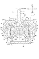
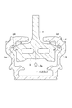
- FIG. 2 is a cross-sectional view taken along the line II-II in FIG. 1 for explaining the reference engagement state of the fixed rail 2 and the movable rail 3 included in the seat slide device 1.
- FIG. 3 is a bottom view of the movable rail 3.
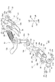
- FIG. 4 is a perspective view showing the main roller 21 and related members included in the movable rail 3, a pair of top wall contact mechanisms K 1, and the slide lock device 12.
- FIG. 5 is a left side view of the top wall contact mechanism K1 in FIG.
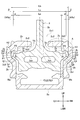
- FIG. 6 is a cross-sectional view at the VI-VI position in FIG.
- FIG. 8 is a cross-sectional view for explaining a state in which the movable rail 3 is moved upward with respect to FIG.
- FIG. 9 is a cross-sectional view for explaining a state in which the movable rail has moved to the upper right with respect to FIG.
- FIGS. 1 to 9 A vehicle seat slide device according to an embodiment will be described with reference to FIGS. 1 to 9 using a seat slide device 1 as a preferred embodiment.
- the forward and backward directions of the vehicle body are indicated as FR, RR, LH, RH, UP, and LWR with the forward direction of the vehicle body as the forward direction. It is shown. Therefore, as a single body of the seat slide device 1, the front-rear direction can be called the longitudinal direction, the left-right direction can be called the width direction, and the up-down direction can be called the height direction.
- FIG. 1 shows a seat slide device 1 including a fixed rail 2 extending in one direction (front-rear direction) and a movable rail 3 that engages with a part of the fixed rail 2 and is movable in the extending direction. It is a perspective view explaining.
- the fixed rail 2 is shown with a part broken for grasping the shape of the movable rail 3.
- 2 is a cross-sectional view taken along the line II-II in FIG.
- FIG. 3 is a bottom view of the movable rail 3.
- the seat slide device 1 includes a fixed rail 2 and a movable rail 3.
- the fixed rail 2 extends in the front-rear direction, and has a cross-sectional shape formed by extrusion molding into a rectangular frame shape having an opening upward. As shown in FIG. 2, the fixed rail 2 has a cross-sectional shape that is symmetrical with respect to a center line CL ⁇ b> 2 that extends vertically.
- the fixed rail 2 includes a bottom wall 2a fixed to the vehicle body, a pair of side walls 2b and 2b erected upward from both left and right ends of the bottom wall 2a, and inward from the tops of the pair of side walls 2b and 2b.
- top walls 2c and 2c Bending and having top walls 2c and 2c extending substantially parallel to the bottom wall 2a so as to face each other.
- the leading edge portions of the top walls 2c, 2c that face each other are spaced apart from each other to form opposed edges 2c1, 2c1.
- the opposing edge portions 2c1 and 2c1 define a slit Dp1 (opening) that is sufficiently wider than the thickness of a plate-like portion 3b (details will be described later) extending in the up-down and front-back directions of the movable rail 3, and are spaced apart in parallel. is doing.
- Support portions 2d and 2d projecting inward so as to approach each other are formed at portions of the inner surfaces 2b1 and 2b1 of the pair of side walls 2b and 2b on the bottom wall 2a side.
- the top surfaces on the front end side of the support portions 2d and 2d are support surfaces 2d1 and 2d1 which are inclined surfaces that incline so as to spread leftward and rightward as they go upward in the cross-sectional shape.
- the support surfaces 2d1 and 2d1 are not limited to planes and may be curved surfaces. In the case of a curved surface, for example, it is formed of a concave circumferential surface or a convex circumferential surface having a circular cross-sectional shape. Here, the case of a concave peripheral surface will be described.
- the support surfaces 2d1 and 2d2 have circular arcs in cross section, and the arcs have a radius from the center Pa located on the center line CL2 above the support portions 2d and 2d, for example, as shown in FIG.
- the arc is Ra.
- the radius Ra is, for example, 25 mm.
- the fixed rail 2 has a substantially rectangular cross-sectional shape surrounded by the side walls 2b, 2b, the top walls 2c, 2c, and the support portions 2d, 2d inside the U-shaped frame shape.
- a rectangular parallelepiped space Va is formed.
- the fixed rail 2 is used in such a posture that the bottom wall 2a is fixed to the floor surface of the vehicle body with a bolt or the like, and the center line CL2 is in a vertical direction in a natural state.
- the movable rail 3 includes a base portion 3a that is housed in the space Va, and a plate-like portion 3b that extends upward in the left-right direction (width direction) center of the base portion 3a and is formed by extrusion molding. Has been.
- a seat cushion frame 51 (illustrated by an alternate long and short dash line in FIG. 2) is connected to an upper portion of the plate-like portion 3b.
- the movable rail 3 is formed symmetrically with respect to the center line CL3.
- the center line CL3 coincides with the center line CL2 of the fixed rail 2.
- the reference engagement state is a natural engagement state between the fixed rail 2 and the movable rail 3, and is an engagement state that serves as a reference in design and use.
- a recess 3a1 is formed which is bent from the bottom surface side.
- the interior of the recess 3a1 is a substantially cubic space Vb.
- the left and right walls of the recess 3a1 are side walls 3a2 and 3a2.
- the main rollers 21 and 21 are rotatably supported on the base 3a.
- pins 22 having an axial direction in the left and right direction are press-fitted and attached to the side walls 3a2 and 3a2 of the base 3a.
- the lower side of the main rollers 21 and 21 protrudes downward from the lower end position of the base portion 3a without being accommodated in the space Vb.
- a pair of main rollers 21 and 21 are externally fitted to the pin 22 so as to be rotatable in a posture that is symmetrical with respect to the center line CL3.
- Each of the pair of main rollers 21 and 21 is formed with a contact portion 21a (FIG. 4) having a larger diameter than other portions on the end portion which is outward in the axial direction.
- the outer peripheral surface of the contact portion 21a includes an abutting surface 21a1 that has an arc shape in the longitudinal cross-sectional shape shown in FIG. 2 and abuts against the support surface 2d1 of the fixed rail 2.
- the arc in the longitudinal cross-sectional shape of the contact surface 21a1 is an arc that becomes smaller in diameter toward the outside in the axial direction.
- This arc is, for example, an arc defined by a radius Rb from a center Pb located on a line segment connecting the center Pa and the support surface 2d1.
- the pair of main rollers 21 and 21 are urged in a direction away from the side wall 3a2, that is, a direction approaching each other, by spring washers 23 and 23 interposed between the left and right ends thereof and the side walls 3a2 and 3a2. .
- the spring washer 23 has a through hole 23a, and a pin 22 is inserted through the through hole 23a.
- a predetermined gap W is formed between the outer surface of the base 3 a of the movable rail 3 and the inner surface of the fixed rail 2 in the reference engagement state.
- the predetermined gap is indicated by, for example, a gap distance Wa in the left-right direction in FIG.
- the downward direction is indicated by a gap distance Wb, for example.
- the upward direction is indicated by, for example, a gap distance Wc (shown only on the right side; the same applies to the left side).
- the movable rail 3 tends to move downward (drop) by the dead weight of the movable rail 3 and the seat connected to the movable rail 3 by the seat cushion frame 51.
- This movement is regulated by the main roller 21 coming into contact with the support portion 2d of the fixed rail 2.
- the movable rail 3 is supported by the fixed rail 2 in the reference engagement state, with the contact surfaces 21a1 and 21a1 of the pair of main rollers 21 and 21 being in point contact with the pair of support surfaces 2d1.
- the point where the contact surface 21a1 makes point contact with the support surface 2d1 is referred to as a support point Ps.
- the seat slide device 1 is adapted to maintain point contact at the support point Ps even when vibrations or impacts caused by traveling of the vehicle body are applied and the movable rail 3 attempts to move upward. . Further, even when the movable rail 3 moves upward and rises instantaneously, a top wall contact mechanism K1 is provided so that the point rail is immediately returned to the support state.
- the top wall abutting mechanism K1 is a mechanism that includes a secondary roller 31 that urges and abuts against the top wall 2c of the fixed rail 2 and urges the fixed rail 2 upward (relatively the movable rail 3 downward).
- a pair of the movable rails 3 are provided apart from each other in the front-rear direction.
- FIG. 4 is a perspective view showing an excerpt of the pair of main rollers 21 and 21 and their related members and the pair of top wall contact mechanisms K1 and K1.
- the movable rail 3 is not shown for easy understanding.
- FIG. 5 is a left side view for explaining the top wall abutting mechanism K1 provided in front of the pair of top wall abutting mechanisms K1, K1 provided on the movable rail 3 (FIG. 4). Arrow view DB diagram).
- the top wall abutting mechanism K1 provided at the rear has the same configuration and is shown in a shape obtained by horizontally reversing the shape shown in FIG.
- the top wall abutting mechanism K1 has a pair of sub-rollers 31 and 31 and is disposed inside the pair of recesses 3a1 and 3a1 in which the main rollers 21 and 21 are provided in the extending direction of the movable rail 3. Yes. Specifically, a pair of accommodating portions 3a3 and 3a3 (see FIG. 3) and escape portions 3g and 3g are formed on the base 3a of the movable rail 3 so as to be turned upward from the lower side. The top wall contact mechanism K1 is accommodated in 3a3 and the escape portion 3g.
- the top wall contact mechanism K1 includes a bracket 32 and a pair of left and right sub-rollers 31 and 31 that are rotatably supported by the bracket 32.
- the top wall abutting mechanism K1 includes a pin 33 that connects the bracket 32 to the movable rail 3, a pair of levers 34 and 34 that urge the bracket 32 around the pin 33, a main body portion 35a, and a holding portion. And a damper 35 having 35b.
- the bracket 32 is formed in a substantially U shape that opens upward in the cross-sectional shape. That is, the bracket 32 includes a bottom portion 32a and a pair of side portions 32b and 32b extending upward from both left and right end portions of the bottom portion 32a.
- a pin 33 is rotatably inserted in the left-right direction slightly forward from the center in the front-rear direction of the pair of side portions 32b, 32b. Both ends of the pin 33 are press-fitted and fixed to the left and right housing side walls 3a4 of the housing portion 3a3 of the base portion 3a (see FIG. 3). Therefore, the bracket 32 is supported by the base 3a so as to be rotatable about the pin 33 as a rotation center. That is, the pair of sub rollers 31 are integrally connected to the base portion 3a via the bracket 32.
- the lever 34 is a spring member formed in a substantially arcuate shape that extends in the front-rear direction and has a central portion that is recessed below both ends.
- a pair of levers 34 are juxtaposed in the left-right direction.
- the lever 34 includes a main body portion 35a of the damper 35 positioned at the upper side with the holding portion 35b attached to the base portion 3a, an upper end portion of the side portion 32b of the bracket 32 positioned on the lower side, and a center portion in the front-rear direction. It is sandwiched between. Further, the lever 34 is at a position where the front and rear end sides (the left end side in FIG. 5) of the movable rail 3 are spaced above the pin 33.
- Sub-rollers 31 and 31 are rotatably supported on the front and rear end sides (left end side in FIG. 5) of the pair of side portions 32b of the bracket 32 so that the horizontal direction is the axial direction. As shown in FIG. 5, the upper ends of the sub-rollers 31, 31 are located higher than the damper 35 and protrude upward.
- the contact surfaces 21 a 1 and 21 a 1 of the main rollers 21 and 21 make point contact with the support surface 2 d 1 of the fixed rail 2.
- the downward movement of the movable rail 3 is restricted.
- the contact surface 21a1 and the support surface 2d1 are formed as peripheral surfaces whose positions become higher as they move away from the center line CL2 in the left direction and the right direction, respectively, the left and right directions of the movable rail 3 are substantially positioned. Is done.
- the top wall contact mechanism K1 is in the state shown in FIG. 5 in the reference engagement state. Specifically, the upper end of the sub-roller 31 contacts the top wall lower surface 2c2 of the top wall 2c of the fixed rail 2, and the bracket 32 presses the main body portion 35a of the damper 35 upward at this contact position. ing. Therefore, the bracket 32 is urged by the main body portion 35a of the damper 35 so as to rotate in the clockwise direction around the pin 33 (see the white arrow Y1). 2c2 is biased upward (see black arrow Y2). That is, the movable rail 3 is pressed downward by the reaction force of the biasing of the fixed rail 2 against the top wall lower surface 2c2 by the pair of sub rollers 31 and 31.
- the movable rail 3 moves smoothly in the front-rear direction by moving the main roller 21 relative to the support surface 2 d 1 and the sub roller 31 relative to the top wall lower surface 2 c 2 relative to the fixed rail 2. It is possible to move to.
- the seat slide device 1 includes a slide lock device 12 that allows the movable rail 3 to be locked to a fixed rail 2 at a desired position among a plurality of fixed positions set at a predetermined pitch in the front-rear direction. ing.
- the slide lock device 12 will be described with reference mainly to FIG. 1, FIG. 3, and FIG.
- the slide lock device 12 has a shaft 12e that is rotatably supported with respect to the movable rail 3 with the vertical direction as an axis.
- An operation lever 12a extending in the horizontal direction is fixed to the upper part of the shaft 12e, and a lever 12f extending in the horizontal direction is fixed to the lower part.
- a shaft portion 12d is provided at the distal end portion of the lever 12f, and a lock plate 12c having a rugged shape at the right edge is rotatably attached to the shaft portion 12d.
- the lock plate 12c is guided by a movement guide portion (not shown) provided on the movable rail 3 side, and moves horizontally without rotation.
- a coil spring 12b is attached between the operation lever 12a and the plate-like portion 3b of the movable rail 3.
- the coil spring 12b urges the shaft portion 12d in the clockwise direction when viewed from above in a natural state.
- the lock plate 12c is further guided through the lever 12f to the movement guide portion and biased so as to move horizontally to the right without rotating (see the white arrow F in FIG. 4).
- the fixed rail 2 is provided with a plurality of lock holes (not shown) at a predetermined pitch in an appropriate position in the longitudinal direction in which the convex and concave portions of the lock plate 12c can be engaged in a natural state. Yes.
- the lock plate 12c in the natural state, can be engaged with any one of the lock holes provided in the fixed rail 2, and the movement of the movable rail 3 in the front-rear direction is restricted by the engagement.
- the user When moving the seat of the vehicle body to a desired front-rear position, first, the user locks the lock plate 12c by turning the operation lever 12a integrated with the shaft portion 12d in the direction opposite to the biasing direction of the coil spring 12b. Remove from the hole and release the lock. In this unlocked state, the movable rail 3 and the seat connected to the movable rail 3 can be manually moved in the front-rear direction with respect to the fixed rail 2. Therefore, after the user moves the seat to a desired position, the user releases the operation lever 12a to the natural state again, and engages the lock plate 12c with the lock hole closest to the desired position to make the lock state again.
- the shaft portion 12d and the lock plate 12c are not directly connected but connected via a lever 12f.
- the position of the shaft portion 12d supported by the movable rail 3 and the position of the lock plate 12c attached to the tip of the lever 12f do not coincide with each other and are shifted in the horizontal direction. Therefore, even if a large external force is applied to the fixed rail 2 in the locked state, the force is not directly applied to the shaft portion 12d from the lock plate 12c engaged with the fixed rail 2. That is, there is little possibility that the movable rail 3 supporting the shaft portion 12d will be deformed.
- the seat slide device 1 even when a force enough to deform the fixed rail 2 is applied to the fixed rail 2 in the locked state of the movable rail 3, the force is applied to the movable rail via the slide lock device 12. 3 is less likely to be transmitted to the movable rail 3 and is less likely to be deformed. Therefore, the increase in sliding resistance due to the deformation of the movable rail 3 does not substantially occur, and the movable rail 3 can be moved smoothly.
- a pair of top wall contact mechanisms K1 is provided in the longitudinal direction (extending direction) of the movable rail 3 with the slide lock device 12 interposed therebetween.
- the spring constants of the lever 34 and the damper 35 of one top wall contact mechanism K1 the spring constants of the lever 34 and the damper 35 of the other top wall contact mechanism K1
- the swing of the movable rail 3 with respect to the fixed rail 2 hardly occurs. Further, even if the swing occurs, the swing amount is small and the damping is fast.
- This swing is a swing in which both ends of the movable rail 3 move up and down with the engagement position between the lock plate 12c and the lock hole as a fulcrum.
- the seat slide device 1 can move the movable rail 3 back and forth smoothly even when the vehicle occupant is seated on a seat connected to the movable rail 3. Further, the lever 34 can be softly received after the fall-down fruit juice applied to the seat back generated when the occupant leans against a well-known seat back (not shown) constituting the seat.
- a predetermined gap is formed between the inner surface of the fixed rail 2 and the outer surface of the movable rail 3.
- the distance of the predetermined gap can be set in consideration of the magnitude of the external force that can be applied to the vehicle body and the rigidity and mass of the fixed rail 2 and the movable rail 3. For example, the greater the external force that can be applied to the vehicle body, the greater the amount of deformation of the fixed rail 2, so the distance of the gap is set larger to allow the deformation.
- the movable rail 3 can be moved smoothly.
- the pair of support portions 2d also approach each other.
- the point Ps is displaced upward. That is, the movable rail 3 is displaced upward.
- a gap exemplified by a gap distance Wc is formed between the movable rail 3 and the fixed rail 2.
- the sub roller 31 is allowed to rotate around the pin 33 that resists the elastic repulsive force while receiving the elastic repulsive force by the damper 35. Therefore, the upward displacement of the movable rail 3 is allowed. Thereby, the smooth movement of the movable rail 3 is maintained and secured.
- the pair of side walls 2b of the fixed rail 2 When the pair of side walls 2b of the fixed rail 2 is expanded and deformed so as to be separated from each other, the pair of support portions 2d are also separated from each other, and the support point Ps is displaced downward. That is, the movable rail 3 is displaced downward. Also in this case, a gap W exemplified by a gap distance Wb is formed below the movable rail 3 with the fixed rail, and the secondary roller 31 is elastically repelled by the damper 35 as described above. Therefore, the movable rail 3 is allowed to move downward. Thereby, the smooth movement of the movable rail 3 is maintained and secured.
- the auxiliary roller 31 When the vertical expansion / contraction deformation of the fixed rail 2 occurs, the auxiliary roller 31 always urges and abuts the top wall lower surface 2c2 regardless of the expansion / contraction deformation by the urging structure of the top wall abutting mechanism K1. Thereby, the smooth movement of the movable rail 3 is maintained and secured.
- the movable rail 3 Since the seat slide device 1 has the gap W between the fixed rail 2 and the movable rail 3, the movable rail 3 is used when the vehicle body vibrates with a large amplitude or when a large impact force is applied to the vehicle body. May be greatly displaced in the space Va upward and in the left-right direction.
- the seat slide device 1 has a structure (also referred to as a return structure K2) that immediately returns to the reference engagement state with respect to the displacement of the movable rail 3 above and in the left-right direction (including the diagonally upward direction). This will be described in detail with reference to FIGS.
- FIG. 6 is a view showing only the fixed rail 2 and the movable rail 3 in the reference engagement state, and is a cross-sectional view taken along the VI-VI position in FIG.
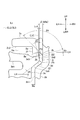
- FIG. 7 is an enlarged view of a portion A in FIG.
- the base 3a of the movable rail 3 has a through hole 3ah penetrating in the longitudinal direction as a lightening hole.
- the return structure K2 includes a fixed rail 2 and a movable rail 3. Since the return structure K2 has a symmetrical shape with respect to the center line CL2 and the center line CL3 that coincide with each other in the reference engagement state, a description will be given mainly of the A portion on the right side in FIG.
- the return structure K2 on the fixed rail 2 side is formed at a connecting portion between the side wall 2b and the top wall 2c.
- a regulation projecting portion 2e that projects in a substantially triangular cross-sectional shape in the space Va is formed.
- the restricting protrusion 2e is parallel to the center line CL2, and extends in the up / down / front / rear direction, a lower plane 2g extending horizontally from the lower end of the side plane 2f and away from the center line CL2,
- An inner inclined surface 2h that is connected to the right end portion of the plane 2g and is inclined upward as it goes to the right is formed.
- the distance in the left-right direction between the pair of left and right side planes 2f, 2f is a distance La (FIG. 6).
- an extended portion 2j whose width expands so as to bulge outwardly corresponding to the restricting protruding portion 2e is formed.
- the extended portion 2j has a lower inclined surface 2j1 that is inclined outward with respect to the inner surface 2b1, and a side bottom surface 2j2 that is connected to the upper end of the lower inclined surface 2j1 and extends in the vertical direction. Further, the upper end of the side bottom surface 2j2 and the right end of the inner inclined surface 2h are connected by a back inclined surface 2k that is inclined downward as it goes outward.
- This back inclined surface 2k is a surface inclined so as to approach the central position (position of the center line CL2) between the pair of side walls 2b as it goes from the bottom wall 2a to the top wall 2c (that is, upward) ( That is, the back inclined surface 2k is “a surface inclined so as to approach the center position between the pair of side walls as it goes from the bottom wall side to the top wall side”.
- the distance in the left-right direction between the pair of left and right side bottom surfaces 2j2, 2j2 is defined as a distance Lb.
- the distance in the left-right direction between the side plane 2f and the side bottom surface 2j2 is defined as a distance ⁇ .
- the return structure K2 on the movable rail 3 side is substantially symmetrical to the shape on the fixed rail 2 side in the upper left and upper right portions of the base 3a, and is formed in a symmetrical shape with respect to the center line CL3.
- the protrusions 3d and 3d formed obliquely upward so as to be separated from the center line CL3 and the vicinity thereof correspond to the upper portions of the pair of side surfaces 3c and 3c in the base portion 3a.
- the upper right protrusion 3d in FIG. 6 and the vicinity thereof will be described with reference to FIG.
- the side surface 3c is formed as a plane extending in the up / down and front / rear direction.
- the protruding portion 3d has a protruding inclined surface 3d1, a return inclined surface 3d2, and an upper inclined surface 3d3.
- the protruding inclined surface 3d1 is an inclined surface that is connected to the upper end of the side surface 3c and goes rightward (outward from the center line) as it goes upward.
- the return inclined surface 3d2 is a surface that is connected to the obliquely upper end of the protruding inclined surface 3d1 and is slightly inclined leftward (toward the center line CL3) as it goes upward.
- the upper inclined surface 3d3 is a surface that is connected to the upper end of the return inclined surface 3d2 and is inclined downward toward the left (toward the center line CL3).
- the protruding inclined surface 3d1 and the return inclined surface 3d2 are gently connected with a relatively large R at the ridgeline (first ridgeline portion) indicated by the connecting portion P1.
- the return inclined surface 3d2 and the upper inclined surface 3d3 have a relatively small R at the ridgeline (second ridgeline portion) indicated by the connection portion P2 and are connected steeply (in short, the cross-section of the ridgeline at P2).
- the curvature is smaller than the curvature of the cross section of the ridgeline at P1).
- the protruding portion 3d has the connecting portion P1 positioned on the outermost side in the left-right direction.
- the distance in the left-right direction between the pair of left and right connecting portions P1, P1 is defined as a distance Lc.
- the inclination angles of the surfaces of the protrusion 3d in the reference engagement state in which the center line CL3 is vertical are represented by the following angles ⁇ 1 to ⁇ 4.
- An inclination angle (subordinate angle) of the protruding inclined surface 3d1 with respect to the horizontal plane LH is defined as an angle ⁇ 1.
- An inclination angle (subordinate angle) of the return inclined surface 3d2 with respect to the vertical surface LV is defined as an angle ⁇ 2.
- An inclination angle (subordinate angle) of the upper inclined surface 3d3 with respect to the horizontal plane LH is defined as an angle ⁇ 3.
- An angle (recess angle) of the back inclined surface 2k with respect to the upper inclined surface 3d3 is defined as an angle ⁇ 4.
- the angles ⁇ 1 to ⁇ 4 are set to the following values, for example.
- the angle ⁇ 1 is about 40 °
- the angle ⁇ 2 is about 14 °
- the angle ⁇ 3 is about 13 °
- the angle ⁇ 4 is about 118 °. These angle values are illustrated for ease of understanding, and do not limit the angle values.
- the protruding inclined surface 3d1 and the lower inclined surface 2j1 of the extended portion 2j of the fixed rail 2 are substantially parallel to each other. Further, the upper inclined surface 3d3 and the inner inclined surface 2h of the extended portion 2j of the fixed rail 2 are substantially parallel to each other.
- the center line CL2 and the center line CL3 coincide with each other. That is, as shown in FIG. 6, when the gap distance between the connecting portion P1 and the side bottom surface 2j2 is a distance ⁇ , the distance ⁇ is equal on the left side and the right side (relative to the center lines CL2 and CL3).
- the gap distance Wa (FIG. 6), which is the distance between the side surface 3c of the base 3a of the movable rail 3 and the inner surface 2b1 of the side wall 2b of the fixed rail 2, is equal to the distance ⁇ . Is set.
- FIG. 8 shows a state in which the movable rail 3 is moved upward from the reference engagement state shown in FIG.
- the protrusion 3d abuts against the restricting protrusion 2e so that the upward movement of the movable rail 3 (see the white arrow Da) does not become excessive, and the upward movement is restricted.
- the distance La is set smaller than the distance Lc (La ⁇ Lc).
- the upper inclined surface 3d3 of the protruding portion 3d is in contact with the inner inclined surface 2h of the restricting protruding portion 2e.
- the pair of left and right inner inclined surfaces 2h, 2h are formed as inclined surfaces that go upward as they move left and right from the center line CL2. Specifically, it is formed as an inclined surface having an angle ⁇ 3 in parallel with the upper inclined surface 3d3 of the base portion 3a. Accordingly, the base 3a urged against the pair of inner inclined surfaces 2h, 2h by the pair of projecting portions 3d, 3d is contacted on the left side and the right side, and the left lower side and the lower right side from the inner inclined surface 2h, respectively. Reaction force F1 and reaction force F2 are applied. As for the reaction force F1 and the reaction force F2, since the pair of inner inclined surfaces 2h have a left-right symmetrical shape, their left-right direction components cancel each other. Therefore, the base portion 3a is not displaced leftward or rightward, and the base portion 3a moves directly below after the upward movement is restricted and shifts to the reference engagement state.
- the restriction of the upward movement of the movable rail 3 by the restriction protrusion 2e is performed in the same manner even when the movable rail 3 is moved upward at a position that is maximally displaced leftward or rightward from the reference engagement state.
- a distance La to a distance Lc, and a distance ⁇ and a distance ⁇ are set.
- the restriction of the upward movement is similarly performed when the movable rail 3 is obliquely moved from the reference engagement state to the upper left or the upper right.
- FIG. 9 shows a cross-sectional view when the movable rail 3 is moved upward with the maximum displacement to the right.
- FIG. 9 is a cross-sectional view corresponding to FIG.
- the state in which the movable rail 3 is positioned upward while being displaced leftward or rightward is referred to as a biased engagement state.
- the state of being displaced upward to one side and positioned upward is also referred to as a maximum biased engagement state.
- the maximum bias engagement state will be described.
- the movable rail 3 is movable to the maximum distance ⁇ (gap distance Wa) from the reference engagement state to the right (the same applies to the left).
- the right side surface 3c of the base portion 3a contacts the inner surface 2b1 of the side wall 2b of the fixed rail 2, and the connection portion P1 also contacts the side bottom surface 2j2 of the extension portion 2j.
- the left protrusion 3d of the base 3a abuts on the left restricting protrusion 2e to restrict further upward movement of the movable rail 3.
- the distance Lc is set larger than the distance obtained by adding the distance La and the distance ⁇ . That is, Lc> La + ⁇ (Formula 3) It is. From (Expression 1) to (Expression 3), the distance La to the distance Lc are Lc> (La + Lb) / 2 (Formula 4) Is set.
- the bias engagement state may occur when the vehicle body vibrates having a large left-right direction component and vertical direction component, or when an impact force is applied to the vehicle body.
- the movement (sliding) of the movable rail 3 with respect to the fixed rail 2 can be performed without any problem even in the biased engagement state, but is basically in the reference engagement state from the stress state generated in each member. It is most desirable to move. Therefore, in the seat slide device 1, by providing the return structure K2, the movable rail 3 that has reached the biased engagement state is actively guided and returned to the reference engagement state.
- the behavior of the movable rail 3 in the maximum biased engagement state shown in FIG. 9, that is, when the movable rail 3 moves upward (white arrow Db) at the position closest to the right side will be described in detail.
- the left protrusion 3d of the base 3a abuts on the restricting protrusion 2e of the fixed rail 2 as described above.
- the upper inclined surface 3d3 of the protruding portion 3d is in urging contact with the inner inclined surface 2h of the restricting protruding portion 2e.
- the protrusion 3d of the base 3a receives a reaction force orthogonal to the inclined surface 2h of the restriction protrusion 2e, that is, a reaction force F3 directed downward to the left, from the restriction protrusion 2e.
- the protruding portion 3d on the right side of the base portion 3a has the connecting portion P2 urged against the back inclined surface 2k of the extended portion 2j of the fixed rail 2.
- a concave portion 3a6 is formed on the upper surface 3a5 of the base portion 3a so as to avoid contact with the restricting protruding portion 2e so that the connecting portion P2 of the protruding portion 3d is urged and brought into contact with the deep inclined surface 2k.
- the inner inclined surface 2k is formed as an inclined surface that goes inward (centerline CL2 side) as it goes upward, the base 3a is opposite to the lower left surface (downward on the centerline CL2 side) from the inner inclined surface 2k. Receives force F4.
- the main forces that the base 3a receives from the fixed rail 2 side are only the reaction force F3 and the reaction force F4.
- the reaction force F3 and the reaction force F4 are both forces that move the base portion 3a to the lower left, so the base portion 3a moves leftward from the state displaced rightward and returns to the reference engagement state.
- the width ARa in the left-right direction in which the back inclined surface 2k is formed is set to be equal to the distance ⁇ (Wa), for example.
- the connecting portion P2 of the projecting portion 3d is not inclined when the base portion 3a moves upward at a position displaced by a predetermined distance or more without being displaced to the maximum right or left.
- the base 3a is in contact with 2k and receives a reaction force that moves in the direction opposite to the displaced left or right direction.
- the predetermined distance is a distance Lc1 shown in FIG. That is, the distance in the left-right direction between the connection portion P2 in the reference engagement state and the connection position between the back inclined surface 2k and the inner inclined surface 2h.
- the distance Lc1 is determined by the angle ⁇ 2, which is the inclination angle of the return inclined surface 3d2, and the distance in the left-right direction between the connection portion P1 and the connection portion P2.
- the distance Lc1 is set to secure a larger upward movable distance even when the base 3a is greatly displaced to the left or right. If the distance Lc1 is increased, the interference area in the left-right direction between the projecting portion 3d and the restricting projecting portion 2e is reduced. Therefore, the distance Lc1 is appropriately set in consideration of the displacement amount allowed for the movable rail 3 in the space Va.
- This distance Lc1 can be set by providing the return inclined surface 3d2. Further, by providing the return inclined surface 3d2, it is possible to increase the thickness of the protruding portion 3d on the tip side. Further, the angle ⁇ 1 and the angle ⁇ 3 of the protruding portion 3d are set so that the root side is thicker than the tip side. That is, angle ⁇ 3 ⁇ angle ⁇ 1. As a result, the base portion 3a moves upward, leftward, or rightward at a high speed due to excessive external force applied to the vehicle body, and collides with any one of the restricting protruding portion 2e, the side bottom surface 2j2, and the back inclined surface 2k. Even in this case, the protrusion 3d is less likely to be deformed or damaged.
- the seat slide device 1 is moved upward in a position where the movable rail 3 is displaced leftward or rightward in the space Va that is a displacement allowable space of the movable rail 3 formed in the fixed rail 2.
- the movable rail 3 can be moved in the longitudinal direction, and is naturally returned to the reference engagement state. Thereby, a more preferable engagement state is always maintained.
- the bracket 32 is configured such that the pair of levers 34, 34 arranged side by side are always urged downward. Accordingly, the pair of sub rollers 31, 31 supported by the bracket 32 always press the top wall lower surfaces 2 c 2, 2 c 2 of the fixed rail 2 upward. Accordingly, the main rollers 21 and 21 attached to the movable rail 3 always press the support surfaces 2d1 and 2d1 of the fixed rail 2 downward. The pressure contact between the sub-rollers 31 and 31 and the main rollers 21 and 21 is continuously maintained without being affected by the vibration to the extent that the vibration is generated during normal traveling of the vehicle body.
- the spring washer 23 is interposed between the main rollers 21 and 21 and the side wall 3a2 of the recess 3a1. Further, the main rollers 21 and 21 and the support surface 2d1 of the fixed rail 2 are in point contact with each other at a support point Ps. As a result, even if the fixed rail 2 or the movable rail 3 is greatly deformed, the support point Ps moves in an arc orbit while maintaining point contact, so that the movable rail 3 moves smoothly with respect to the fixed rail 2.
- the bracket 32 and the auxiliary rollers 31 and 31 of the top wall contact mechanism K1 are assembled in advance and unitized. Accordingly, the number of assembly steps in the assembly line such as the fixed rail 2 can be reduced. Thereby, the assembly work process of various members is simplified.
- the contact surface 21a1 of the main roller 21 is a convex circumferential surface and the support surface 2d1 of the fixed rail 2 is a concave circumferential surface.
- the present invention is not limited to this.
- the contact surface 21a1 may be a convex circumferential surface and the support surface 2d1 may be an inclined plane.
- the contact surface 21a1 may be an inclined plane and the support surface 2d1 may be a convex circumferential surface. That is, it is only necessary that at least one surface (contact surface) of the contact surface 21a1 and the support surface 2d1 is formed as a convex curved surface so as to be in point contact.
- the configuration in which the movable rail 3 is supported by the pair of left and right support portions 2d extending from the pair of side walls 2b of the fixed rail 2 has been described, but is not limited thereto.
- the support portion 2d may extend from the bottom wall 2a of the fixed rail 2, or the support portion 2d may be provided at one central location to support point contact.
- the vehicle is not limited to an automobile, but may be a mobile body that includes a vehicle body having a seat, such as an aircraft, a ship, and a railway vehicle body, and moves while the passenger is seated on the seat.
- a vehicle body having a seat such as an aircraft, a ship, and a railway vehicle body, and moves while the passenger is seated on the seat.
- the present invention can be used for a seat slide device that slides a seat mounted on a vehicle (automobile, aircraft, ship, railway car body, etc.) that moves an occupant in a seated state.
- a vehicle autonomous, aircraft, ship, railway car body, etc.
Landscapes
- Engineering & Computer Science (AREA)
- Aviation & Aerospace Engineering (AREA)
- Transportation (AREA)
- Mechanical Engineering (AREA)
- Seats For Vehicles (AREA)
Abstract
シートスライド装置(1)は、底壁(2a)と一対の側壁(2b)と底壁(2a)と平行かつ先端縁部(2c1)が離隔した一対の頂壁(2c)とを有する横断面枠状の固定レール(2)と、固定レール(2)内に間隙を有して配置された基部(3a)と一対の頂壁(2c)の内面に付勢転動する副ローラ(31)及び一対の側壁(2b)から延出した支持部(2d)に転動する主ローラ(21)とを有して固定レール(2)内で移動する可動レール(3)と、を備える。基部(3a)は一対の側壁(2b)へ向かい突出する一対の突出部(3d)を有する。一対の側壁(2b)それぞれは、底壁(2a)側から頂壁(2c)側に向かうにつれて一対の側壁(2b)間の中央に接近傾斜する面(2k)であって、基部(3a)が一対の側壁(2b)の一方側に変位し一対の頂壁(2c)に接近移動したときに突出部(3d)に当接する傾斜面(2k)を有する。
Description
本発明は、乗り物用シートスライド装置に関する。
特開平8-127270号公報(特許文献1)に、乗り物用シートスライド装置の例が記載されている。
特許文献1に記載された乗り物用シートスライド装置は、固定レールと、可動レールと、ローラと、を有する。
固定レールは、乗り物の車体の床面などに固定され、横断面形状が、上部に開口部を有する略矩形枠状に形成されている。
可動レールは、上方部位がシート(座席)に取り付けられ下方部位が固定レールの開口部から内部に進入して固定レールの枠状内部に係合している。
ローラは、可動レールの長手方向の両端部に設けられ固定レールの内面に対し転動可能とされている。
この構成により、固定レールに対し可動レールを長手方向に摺動可能であり、可動レールが取り付けられたシートを長手方向にスライドさせることができる。
特許文献1に記載された乗り物用シートスライド装置は、固定レールと、可動レールと、ローラと、を有する。
固定レールは、乗り物の車体の床面などに固定され、横断面形状が、上部に開口部を有する略矩形枠状に形成されている。
可動レールは、上方部位がシート(座席)に取り付けられ下方部位が固定レールの開口部から内部に進入して固定レールの枠状内部に係合している。
ローラは、可動レールの長手方向の両端部に設けられ固定レールの内面に対し転動可能とされている。
この構成により、固定レールに対し可動レールを長手方向に摺動可能であり、可動レールが取り付けられたシートを長手方向にスライドさせることができる。
また、可動レールには、上下動可能で通常下方に付勢されるロックレバーが設けられ、固定レールの底壁には、下降したロックレバーに係合する複数のロック孔が形成されている。ロックレバーは、固定レールに対し可動レールを摺動させて任意のロック孔に係合させることができるようになっている。
これにより、使用者は、シートをスライドして所望の位置にロックすることができる。
これにより、使用者は、シートをスライドして所望の位置にロックすることができる。
特許文献1に記載された乗り物用シートスライド装置は、可動レールが固定レールに対してほぼ隙間なく係合している。
従って、車体に大きな外力が加わるなどの原因によって、車体に固定された固定レールが変形すると、固定レールに対する可動レールの摺動抵抗が大きくなって、可動レールがスムースに移動できなくなる虞がある。
従って、車体に大きな外力が加わるなどの原因によって、車体に固定された固定レールが変形すると、固定レールに対する可動レールの摺動抵抗が大きくなって、可動レールがスムースに移動できなくなる虞がある。
また、ロックレバーをロック孔に係合させたロック状態で固定レールに対し大きな外力が加わると、固定レールからロックレバーを介して可動レールに大きな力が加わり、固定レールのみならず可動レールの変形が生じる虞がある。
この場合、固定レールと可動レールとの両方に変形が生じるので摺動抵抗が一段と大きくなって、スムースな移動がより難しくなることが懸念される。
この場合、固定レールと可動レールとの両方に変形が生じるので摺動抵抗が一段と大きくなって、スムースな移動がより難しくなることが懸念される。
そこで、本発明は、固定レール又は可動レールが変形しても、固定レールに対する可動レールの移動がスムースに行える乗り物用シートスライド装置を提供することを目的とする。
本発明の一つの態様によれば、横断面形状が、底壁と、対向する一対の側壁と、前記底壁と平行に、かつ先端縁部同士が対向離隔するよう設けられた一対の頂壁と、を有して矩形枠状を呈し一方向に延びる固定レールと、前記固定レール内に、前記底壁,前記一対の側壁,及び前記一対の頂壁との間に間隙を有して配置された基部と、前記基部に連結され前記一対の頂壁の内面に付勢当接する副ローラと、前記基部に取り付けられ前記底壁又は前記一対の側壁から延出した支持部に当接する主ローラと、を有し、前記副ローラ及び前記主ローラが転動して前記固定レールに対して移動する可動レールと、を備え、
前記基部は、前記一対の側壁それぞれに向かって突出する一対の突出部を有し、
前記一対の側壁それぞれは、前記底壁側から前記頂壁側に向かうに従って前記一対の側壁間の中央位置に接近するよう傾斜した面であって、前記基部が前記一対の側壁のいずれかの側に変位しつつ前記一対の頂壁に接近するよう移動したときに前記突出部に当接する傾斜面を有しているシートスライド装置が提供される。
前記基部は、前記一対の側壁それぞれに向かって突出する一対の突出部を有し、
前記一対の側壁それぞれは、前記底壁側から前記頂壁側に向かうに従って前記一対の側壁間の中央位置に接近するよう傾斜した面であって、前記基部が前記一対の側壁のいずれかの側に変位しつつ前記一対の頂壁に接近するよう移動したときに前記突出部に当接する傾斜面を有しているシートスライド装置が提供される。
本発明の乗り物用シートスライド装置によれば、固定レール又は可動レールが変形しても、固定レールに対する可動レールの移動がスムースに行える。
図1~図9を参照し、実施の形態に係る乗り物用シートスライド装置を、好ましい実施例であるシートスライド装置1により説明する。
図1~図9では、シートスライド装置1が乗り物の車体に取り付けられた状態での、車体の前進方向を前方として前後左右上下の各方向を、FR,RR,LH,RH,UP,LWRとして示してある。
従って、シートスライド装置1の単体としては、前後方向を長手方向、左右方向を幅方向、上下方向を高さ方向、と呼ぶことができる。
図1~図9では、シートスライド装置1が乗り物の車体に取り付けられた状態での、車体の前進方向を前方として前後左右上下の各方向を、FR,RR,LH,RH,UP,LWRとして示してある。
従って、シートスライド装置1の単体としては、前後方向を長手方向、左右方向を幅方向、上下方向を高さ方向、と呼ぶことができる。
(実施例)
まず、図1~図3を参照してシートスライド装置1の全体の概略構成について説明する。
図1は、一方向(前後方向)に延びる固定レール2と、固定レール2の一部に係合してその延在方向に移動可能な可動レール3と、を含んでなるシートスライド装置1を説明する斜視図である。図1において、固定レール2は、可動レール3の形状把握のため、一部を破断して記載してある。
図2は、図1におけるII-II位置での矢視断面図である。
図3は、可動レール3の底面図である。
まず、図1~図3を参照してシートスライド装置1の全体の概略構成について説明する。
図1は、一方向(前後方向)に延びる固定レール2と、固定レール2の一部に係合してその延在方向に移動可能な可動レール3と、を含んでなるシートスライド装置1を説明する斜視図である。図1において、固定レール2は、可動レール3の形状把握のため、一部を破断して記載してある。
図2は、図1におけるII-II位置での矢視断面図である。
図3は、可動レール3の底面図である。
シートスライド装置1は、固定レール2及び可動レール3を有する。
固定レール2は、前後方向に延び、横断面形状が、上方に開口を有する矩形枠状に押し出し成形によって形成されている。
図2に示されるように、固定レール2は、横断面形状が、上下に延びる中心線CL2に対して左右対称に形成されている。
固定レール2は、車体に固定される底壁2aと、底壁2aの左右両端部から上方に立設された一対の側壁2b,2bと、一対の側壁2b,2bの各頂部から内方へ屈曲し、互いに対向接近するよう底壁2aに略平行に延設された頂壁2c,2cと、を有する。
頂壁2c,2cの対向する先端縁部同士は対向離隔し、対向縁部2c1,2c1とされる。
対向縁部2c1,2c1は、可動レール3の上下前後方向に延在する板状部3b(詳細後述)の厚さよりも十分に幅が広いスリットDp1(開口部)を画成し、平行に離隔している。
固定レール2は、前後方向に延び、横断面形状が、上方に開口を有する矩形枠状に押し出し成形によって形成されている。
図2に示されるように、固定レール2は、横断面形状が、上下に延びる中心線CL2に対して左右対称に形成されている。
固定レール2は、車体に固定される底壁2aと、底壁2aの左右両端部から上方に立設された一対の側壁2b,2bと、一対の側壁2b,2bの各頂部から内方へ屈曲し、互いに対向接近するよう底壁2aに略平行に延設された頂壁2c,2cと、を有する。
頂壁2c,2cの対向する先端縁部同士は対向離隔し、対向縁部2c1,2c1とされる。
対向縁部2c1,2c1は、可動レール3の上下前後方向に延在する板状部3b(詳細後述)の厚さよりも十分に幅が広いスリットDp1(開口部)を画成し、平行に離隔している。
一対の側壁2b,2bの内面2b1,2b1における底壁2a側の部位には、互いに接近するよう内方へ突出する支持部2d,2dが形成されている。
支持部2d,2dの先端側の上面は、横断面形状において、上方に向かうに従って、それぞれ左方,右方に互いに広がるように傾斜する傾斜面である支持面2d1,2d1とされている。
支持面2d1,2d1は、平面に限定されず曲面であってもよい。曲面の場合は、例えば横断面形状が円弧状となる凹周面又は凸周面で形成されている。
ここでは、凹周面の場合を説明する。
すなわち、支持面2d1,2d2は横断面形状が円弧を呈し、その円弧は、例えば、図2に示されるように、支持部2d,2dよりも上方の中心線CL2上に位置する中心Paから半径Raとなる円弧とされる。半径Raは例えば25mmである。
支持部2d,2dの先端側の上面は、横断面形状において、上方に向かうに従って、それぞれ左方,右方に互いに広がるように傾斜する傾斜面である支持面2d1,2d1とされている。
支持面2d1,2d1は、平面に限定されず曲面であってもよい。曲面の場合は、例えば横断面形状が円弧状となる凹周面又は凸周面で形成されている。
ここでは、凹周面の場合を説明する。
すなわち、支持面2d1,2d2は横断面形状が円弧を呈し、その円弧は、例えば、図2に示されるように、支持部2d,2dよりも上方の中心線CL2上に位置する中心Paから半径Raとなる円弧とされる。半径Raは例えば25mmである。
図2に示されるように、固定レール2は、U字枠状の内部に、側壁2b,2bと頂壁2c,2cと支持部2d,2dとで概ね囲まれた横断面形状が略矩形を呈する直方体状の空間Vaが形成されている。
固定レール2は、底壁2aが車体の床面にボルトなどにより固定され、自然状態で中心線CL2が鉛直方向となる姿勢で使用される。
固定レール2は、底壁2aが車体の床面にボルトなどにより固定され、自然状態で中心線CL2が鉛直方向となる姿勢で使用される。
可動レール3は、空間Va内に収められる基部3aと、基部3aの左右方向(幅方向)の中央において上方に向け板状に延出する板状部3bと、を有し、押し出し成形により形成されている。
板状部3bにおける上部には、シートのフレーム部材であるシートクッションフレーム51(図2において一点鎖線で図示)が連結されている。
可動レール3は、中心線CL3に対して左右対称形状に形成されている。
板状部3bにおける上部には、シートのフレーム部材であるシートクッションフレーム51(図2において一点鎖線で図示)が連結されている。
可動レール3は、中心線CL3に対して左右対称形状に形成されている。
図2に示される、可動レール3の固定レール2に対する基準係合状態において、中心線CL3は、固定レール2の中心線CL2と一致する。
基準係合状態は、固定レール2と可動レール3との自然係合状態であり、設計上及び使用上の基準となる係合状態である。
基準係合状態は、固定レール2と可動レール3との自然係合状態であり、設計上及び使用上の基準となる係合状態である。
基部3aの前端側及び後端側には、底面側から抉られた凹部3a1が形成されている。凹部3a1の内部は、略立方体状の空間Vbとされる。また、凹部3a1の左右の壁は、側壁3a2,3a2である。
空間Vbには、主ローラ21,21が、基部3aに回転自在に軸支されて収容されている。
詳しくは、空間Vb内には、左右方向を軸線方向とするピン22が、その両端部を基部3aの側壁3a2,3a2に圧入装着されている。また、主ローラ21,21の下方側は、空間Vbに収容されずに基部3aの下端位置から下方に突出している。
空間Vbには、主ローラ21,21が、基部3aに回転自在に軸支されて収容されている。
詳しくは、空間Vb内には、左右方向を軸線方向とするピン22が、その両端部を基部3aの側壁3a2,3a2に圧入装着されている。また、主ローラ21,21の下方側は、空間Vbに収容されずに基部3aの下端位置から下方に突出している。
ピン22には、一対の主ローラ21,21が、中心線CL3を挟んで左右対称となる姿勢で回転自在に外嵌されている。
一対の主ローラ21,21は、それぞれ軸方向において外方となる端部側に、他の部位より大径の接触部21a(図4)が形成されている。
接触部21aの外周面には、図2に示される縦断面形状で円弧状を呈して固定レール2の支持面2d1に当接する当接面21a1が含まれている。
当接面21a1の縦断面形状での円弧は、軸方向の外方に向かうに従って小径となる円弧である。この円弧は、例えば中心Paと支持面2d1とを繋ぐ線分上に位置する中心Pbから半径Rbで規定される円弧である。
当接面21a1の半径Rbは、支持面2d1の半径Raよりも小さい。例えばRb=20mmである。
一対の主ローラ21,21は、それぞれ軸方向において外方となる端部側に、他の部位より大径の接触部21a(図4)が形成されている。
接触部21aの外周面には、図2に示される縦断面形状で円弧状を呈して固定レール2の支持面2d1に当接する当接面21a1が含まれている。
当接面21a1の縦断面形状での円弧は、軸方向の外方に向かうに従って小径となる円弧である。この円弧は、例えば中心Paと支持面2d1とを繋ぐ線分上に位置する中心Pbから半径Rbで規定される円弧である。
当接面21a1の半径Rbは、支持面2d1の半径Raよりも小さい。例えばRb=20mmである。
一対の主ローラ21,21は、その左右両端部と側壁3a2,3a2との間に介装されたばねワッシャ23,23によって、側壁3a2から離れる方向、すなわち、互いに接近する方向に付勢されている。
図4に示されるように、ばねワッシャ23は、貫通孔23aを有し、貫通孔23aにピン22が挿通されて介装されている。
図4に示されるように、ばねワッシャ23は、貫通孔23aを有し、貫通孔23aにピン22が挿通されて介装されている。
図2に示されるように、基準係合状態において、可動レール3の基部3aの外面と、固定レール2の内面と、の間には、所定の間隙Wが形成されるようになっている。
所定の間隙は、図2の左右方向については、例えば間隙距離Waで示される。また、下方向については、例えば間隙距離Wbで示される。上方向については、例えば間隙距離Wcで示される(右方のみ図示。左方も同様)。
基準係合状態において、可動レール3及び可動レール3に対してシートクッションフレーム51で連結されたシートの自重によって、可動レール3は下方に移動(落下)しようとする。
この移動は、主ローラ21が、固定レール2の支持部2dに当接することで規制される。
詳しくは、可動レール3は、基準係合状態で、一対の主ローラ21,21の当接面21a1,21a1が、一対の支持面2d1それぞれに対し点接触して固定レール2に支持されている。
以下、支持面2d1に対し当接面21a1が点接触する点を支持点Psと称する。
所定の間隙は、図2の左右方向については、例えば間隙距離Waで示される。また、下方向については、例えば間隙距離Wbで示される。上方向については、例えば間隙距離Wcで示される(右方のみ図示。左方も同様)。
基準係合状態において、可動レール3及び可動レール3に対してシートクッションフレーム51で連結されたシートの自重によって、可動レール3は下方に移動(落下)しようとする。
この移動は、主ローラ21が、固定レール2の支持部2dに当接することで規制される。
詳しくは、可動レール3は、基準係合状態で、一対の主ローラ21,21の当接面21a1,21a1が、一対の支持面2d1それぞれに対し点接触して固定レール2に支持されている。
以下、支持面2d1に対し当接面21a1が点接触する点を支持点Psと称する。
シートスライド装置1は、車体の走行に伴い生じる振動や衝撃等が付与されて、可動レール3が上方に移動しようとした場合にも、支持点Psにおける点接触が維持されるようになっている。また、可動レール3が上方移動して瞬間的に浮き上がった場合にも、直ちに点接触での支持状態に戻るように、頂壁当接機構K1が設けられている。
この頂壁当接機構K1は、固定レール2の頂壁2cに付勢当接する副ローラ31を備えて固定レール2を上方に(相対的に可動レール3を下方に)付勢する機構であり、可動レール3の前後方向に離隔して一対設けられている。
次に、頂壁当接機構K1について、図3~図5を主に参照して説明する。
この頂壁当接機構K1は、固定レール2の頂壁2cに付勢当接する副ローラ31を備えて固定レール2を上方に(相対的に可動レール3を下方に)付勢する機構であり、可動レール3の前後方向に離隔して一対設けられている。
次に、頂壁当接機構K1について、図3~図5を主に参照して説明する。
図4は、一対の主ローラ21,21及びその関連部材と、一対の頂壁当接機構K1,K1と、を抜粋して示した斜視図である。可動レール3は理解容易のため不図示としてある。
図5は、可動レール3に設けられた一対の頂壁当接機構K1,K1の内の、前方に設けられた頂壁当接機構K1を説明するための左側面図である(図4の矢視DB図)。後方に設けられた頂壁当接機構K1は、同じ構成であって図5の記載形状を左右反転した形状で示される。
図5は、可動レール3に設けられた一対の頂壁当接機構K1,K1の内の、前方に設けられた頂壁当接機構K1を説明するための左側面図である(図4の矢視DB図)。後方に設けられた頂壁当接機構K1は、同じ構成であって図5の記載形状を左右反転した形状で示される。
頂壁当接機構K1は、一対の副ローラ31,31を有し、可動レール3の延在方向において主ローラ21,21が設けられた一対の凹部3a1,3a1よりも内側に一対配置されている。
具体的には、可動レール3の基部3aに、下方側から上方に向け抉られて一対の収容部3a3,3a3(図3参照)と逃げ部3g,3gとが形成されており、各収容部3a3及び逃げ部3g内に頂壁当接機構K1が収容されている。
具体的には、可動レール3の基部3aに、下方側から上方に向け抉られて一対の収容部3a3,3a3(図3参照)と逃げ部3g,3gとが形成されており、各収容部3a3及び逃げ部3g内に頂壁当接機構K1が収容されている。
頂壁当接機構K1は、概略構成として、ブラケット32と、ブラケット32に回転自在に支持された左右一対の副ローラ31,31と、を有する。また、頂壁当接機構K1は、ブラケット32を可動レール3に連結するピン33と、ブラケット32をピン33のまわりに回動付勢する一対のレバー34,34と、本体部35a及び保持部35bを有するダンパ35と、を有する。
ブラケット32は、横断面形状において上方に開口する略U字形状に形成されている。すなわち、ブラケット32は、底部32aと、底部32aの左右両端部それぞれから上方に延出した一対の側部32b,32bと、を有する。
一対の側部32b,32bの前後方向における中央からやや前方寄りには、左右方向にピン33が回転自在に挿通されている。
ピン33の両端部は、基部3aの収容部3a3の左右の収容側壁3a4に圧入固定されている(図3参照)。
従って、基部3aに対し、ブラケット32は、ピン33を回動中心として回動可能に支持されている。すなわち、一対の副ローラ31は、基部3aに対しブラケット32を介して一体的に連結されている。
ブラケット32は、横断面形状において上方に開口する略U字形状に形成されている。すなわち、ブラケット32は、底部32aと、底部32aの左右両端部それぞれから上方に延出した一対の側部32b,32bと、を有する。
一対の側部32b,32bの前後方向における中央からやや前方寄りには、左右方向にピン33が回転自在に挿通されている。
ピン33の両端部は、基部3aの収容部3a3の左右の収容側壁3a4に圧入固定されている(図3参照)。
従って、基部3aに対し、ブラケット32は、ピン33を回動中心として回動可能に支持されている。すなわち、一対の副ローラ31は、基部3aに対しブラケット32を介して一体的に連結されている。
図4及び図5に示されるように、レバー34は、前後方向に延び、中央部が両端部よりも下方に凹となる略弓型状に形成されたばね部材である。
レバー34は左右方向に一対並設されている。
レバー34は、前後方向の中央部位において、基部3aに保持部35bが取り付けられて上方に位置するダンパ35の本体部35aと、下方側に位置するブラケット32の側部32bの上方端部と、の間に挟まれている。
また、レバー34は、可動レール3の前後両端側(図5では左方端側)が、ピン33の上方に離隔した位置にある。
レバー34は左右方向に一対並設されている。
レバー34は、前後方向の中央部位において、基部3aに保持部35bが取り付けられて上方に位置するダンパ35の本体部35aと、下方側に位置するブラケット32の側部32bの上方端部と、の間に挟まれている。
また、レバー34は、可動レール3の前後両端側(図5では左方端側)が、ピン33の上方に離隔した位置にある。
ブラケット32における一対の側部32bの前後両端側(図5では左方端側)には、それぞれ左右方向を軸線方向とする姿勢で副ローラ31,31が回転自在に支持されている。
図5に示されるように、副ローラ31,31の上端は、ダンパ35よりも高く上方に突出した位置にある。
図5に示されるように、副ローラ31,31の上端は、ダンパ35よりも高く上方に突出した位置にある。
シートスライド装置1は、図2に示される固定レール2に対する可動レール3の基準係合状態において、主ローラ21,21の当接面21a1,21a1が、固定レール2の支持面2d1それぞれに点接触し、可動レール3の下方への移動が規制されている。
また、当接面21a1及び支持面2d1は、それぞれ中心線CL2から左方向及び右方向に離れるほど位置が高くなる周面として形成されているので、実質的に、可動レール3の左右方向も位置決めされる。
また、当接面21a1及び支持面2d1は、それぞれ中心線CL2から左方向及び右方向に離れるほど位置が高くなる周面として形成されているので、実質的に、可動レール3の左右方向も位置決めされる。
頂壁当接機構K1は、基準係合状態において、図5に示された状態となる。
詳しくは、副ローラ31の上端が、固定レール2の頂壁2cの頂壁下面2c2に当接し、この当接位置において、ブラケット32が、ダンパ35の本体部35aを上方に押圧するようになっている。
従って、ブラケット32は、ダンパ35の本体部35aによってピン33を中心とする時計まわり方向に回動するよう付勢され(白矢印Y1参照)、この付勢によって、副ローラ31は、頂壁下面2c2を上方に付勢する(黒矢印Y2参照)。
すなわち、可動レール3は、一対の副ローラ31,31による固定レール2の頂壁下面2c2への付勢の反力によって、下方に押し付けられる。
この反力は、一対の主ローラ21,21の当接面21a1,21a1から支持面2d1,2d1に伝達される。
従って、固定レール2に対し、可動レール3は、重力と副ローラ31が頂壁下面2c2を付勢する力の反力とで固定レール2を下方に押しつつ上下方向に位置決めされる。
これにより、固定レール2の空間Va内における、可動レール3の左右方向及び上下方向の位置が決められる。
詳しくは、副ローラ31の上端が、固定レール2の頂壁2cの頂壁下面2c2に当接し、この当接位置において、ブラケット32が、ダンパ35の本体部35aを上方に押圧するようになっている。
従って、ブラケット32は、ダンパ35の本体部35aによってピン33を中心とする時計まわり方向に回動するよう付勢され(白矢印Y1参照)、この付勢によって、副ローラ31は、頂壁下面2c2を上方に付勢する(黒矢印Y2参照)。
すなわち、可動レール3は、一対の副ローラ31,31による固定レール2の頂壁下面2c2への付勢の反力によって、下方に押し付けられる。
この反力は、一対の主ローラ21,21の当接面21a1,21a1から支持面2d1,2d1に伝達される。
従って、固定レール2に対し、可動レール3は、重力と副ローラ31が頂壁下面2c2を付勢する力の反力とで固定レール2を下方に押しつつ上下方向に位置決めされる。
これにより、固定レール2の空間Va内における、可動レール3の左右方向及び上下方向の位置が決められる。
シートスライド装置1において、固定レール2に対し、可動レール3は、主ローラ21が支持面2d1に対し転動し、副ローラ31が頂壁下面2c2に対し転動することで、スムースに前後方向に移動可能となっている。
また、シートスライド装置1は、固定レール2に対し、可動レール3を、前後方向に所定ピッチで設定された複数の固定位置の内の、所望の位置でロック可能とするスライドロック装置12を備えている。
このスライドロック装置12について、図1,図3,及び図4を主に参照して説明する。
このスライドロック装置12について、図1,図3,及び図4を主に参照して説明する。
スライドロック装置12は、可動レール3に対し、上下方向を軸線として回転自在に支持された軸12eを有する。
軸12eの上部には、水平方向に延在する操作レバー12aが固定され、下部には水平方向に延在するレバー12fが固定されている。
レバー12fの先端部位には、軸部12dが設けられ、軸部12dには右方縁部が凹凸形状とされたロックプレート12cが回動自在に取り付けられている。
このロックプレート12cは、軸部12dが回動したときに、可動レール3側に設けられた移動案内部(図示せず)によって案内されて、非回動で水平移動するようになっている。
また、操作レバー12aと、可動レール3の板状部3bと、の間には、コイルスプリング12bが取り付けられている。
コイルスプリング12bは、自然状態で、軸部12dを、上方からみたときの時計回り方向に付勢している。これにより、ロックプレート12cは、レバー12fを介し、さらに移動案内部に案内されて右方に非回動で水平移動するように(図4の白矢印F参照)付勢される。
軸12eの上部には、水平方向に延在する操作レバー12aが固定され、下部には水平方向に延在するレバー12fが固定されている。
レバー12fの先端部位には、軸部12dが設けられ、軸部12dには右方縁部が凹凸形状とされたロックプレート12cが回動自在に取り付けられている。
このロックプレート12cは、軸部12dが回動したときに、可動レール3側に設けられた移動案内部(図示せず)によって案内されて、非回動で水平移動するようになっている。
また、操作レバー12aと、可動レール3の板状部3bと、の間には、コイルスプリング12bが取り付けられている。
コイルスプリング12bは、自然状態で、軸部12dを、上方からみたときの時計回り方向に付勢している。これにより、ロックプレート12cは、レバー12fを介し、さらに移動案内部に案内されて右方に非回動で水平移動するように(図4の白矢印F参照)付勢される。
一方、固定レール2には、自然状態で、ロックプレート12cにおける凹凸形状の凸部分が係合可能とされたロック孔(図示せず)が、長手方向の適宜位置に所定ピッチで複数設けられている。
この構成により、自然状態において、ロックプレート12cは、固定レール2に設けられたロック孔のいずれかに係合可能であり、係合によって可動レール3の前後方向の移動が規制される。
車体のシートを所望の前後位置に移動させる場合、まず、使用者は、軸部12dに一体化された操作レバー12aを、コイルスプリング12bの付勢方向と反対方向に回してロックプレート12cをロック孔から離脱させ、ロックを解除する。
このロック解除状態で、可動レール3及び可動レール3に連結されたシートは、手動により固定レール2に対して前後方向に移動可能となる。
そこで、使用者は、シートを所望の位置に移動した後、操作レバー12aを再び自然状態に解放し、ロックプレート12cを所望位置に最も近いロック孔に係合させて再度ロック状態とする。
このロック解除状態で、可動レール3及び可動レール3に連結されたシートは、手動により固定レール2に対して前後方向に移動可能となる。
そこで、使用者は、シートを所望の位置に移動した後、操作レバー12aを再び自然状態に解放し、ロックプレート12cを所望位置に最も近いロック孔に係合させて再度ロック状態とする。
スライドロック装置12は、軸部12dと、ロックプレート12cと、を直接連結せず、レバー12fを介して連結している。これにより、可動レール3に支持された軸部12dの位置と、レバー12fの先端に取り付けられたロックプレート12cの位置と、は一致せず、水平方向にずれている。
そのため、ロック状態で固定レール2に大きな外力が加わっても、その力が、固定レール2に係合しているロックプレート12cから軸部12dに直接加わることがない。すなわち、軸部12dを支持する可動レール3に変形が生じる虞が少ない。
そのため、ロック状態で固定レール2に大きな外力が加わっても、その力が、固定レール2に係合しているロックプレート12cから軸部12dに直接加わることがない。すなわち、軸部12dを支持する可動レール3に変形が生じる虞が少ない。
このように、シートスライド装置1では、可動レール3のロック状態で、固定レール2に対し固定レール2を変形させるほどの力が付与されても、その力がスライドロック装置12を介して可動レール3に伝達しにくく、可動レール3が変形する虞が小さい。
従って、可動レール3の変形に起因する摺動抵抗の増加は実質的に発生せず、可動レール3の移動がスムースに行える。
従って、可動レール3の変形に起因する摺動抵抗の増加は実質的に発生せず、可動レール3の移動がスムースに行える。
頂壁当接機構K1は、このスライドロック装置12を挟んで、可動レール3の長手方向(延在方向)に一対設けられている。
一対の頂壁当接機構K1,K1において、一方の頂壁当接機構K1のレバー34及びダンパ35のばね定数と、他方の頂壁当接機構K1のレバー34及びダンパ35のばね定数と、を異ならせておくとよりよい。
これにより、固定レール2に対する可動レール3の揺動が生じにくい。また、揺動が生じても揺動量は少なく、減衰も速い。
この揺動は、可動レール3の、ロックプレート12cとロック孔との係合位置を支点として両端部側が上下動する揺動である。
一対の頂壁当接機構K1,K1において、一方の頂壁当接機構K1のレバー34及びダンパ35のばね定数と、他方の頂壁当接機構K1のレバー34及びダンパ35のばね定数と、を異ならせておくとよりよい。
これにより、固定レール2に対する可動レール3の揺動が生じにくい。また、揺動が生じても揺動量は少なく、減衰も速い。
この揺動は、可動レール3の、ロックプレート12cとロック孔との係合位置を支点として両端部側が上下動する揺動である。
また、シートスライド装置1は、車体の乗員が可動レール3に連結されたシートに着座した状態でも可動レール3はスムースに前後動できる。また、座席を構成する図示しない周知のシートバックに乗員がもたれかかることにより発生するシートバックに加わる後倒れ果汁を、レバー34が柔軟にしなることで柔らかく受けることができる。
シートスライド装置1は、固定レール2の内面と、可動レール3の外面と、の間に、所定の間隙が形成されている。
この所定の間隙の距離は、車体に付与され得る外力の大きさ、並びに、固定レール2及び可動レール3の剛性や質量を考慮して設定することができる。
例えば、車体に付与され得る外力が大きいほど、固定レール2の変形量が大きくなり得るので、その変形を許容すべく間隙の距離を大きく設定する。
これにより、車体に外力が付与されることなどによって固定レール2が変形しても、固定レール2が可動レール3に接触する可能性は小さく、摺動抵抗が大幅に増加することがないので、可動レール3のスムースな移動が行える。
この所定の間隙の距離は、車体に付与され得る外力の大きさ、並びに、固定レール2及び可動レール3の剛性や質量を考慮して設定することができる。
例えば、車体に付与され得る外力が大きいほど、固定レール2の変形量が大きくなり得るので、その変形を許容すべく間隙の距離を大きく設定する。
これにより、車体に外力が付与されることなどによって固定レール2が変形しても、固定レール2が可動レール3に接触する可能性は小さく、摺動抵抗が大幅に増加することがないので、可動レール3のスムースな移動が行える。
車体が大きな力の付与により変形し、それに伴い、図2に示された固定レール2の一対の側壁2bが、互いに接近するように変形した場合、一対の支持部2dも互いに接近するため、支持点Psは上方に変位する。すなわち、可動レール3が上方に変位する。
この場合も、可動レール3の上方には、固定レール2との間に、間隙距離Wcで例示される間隙が形成されている。また、図5から明らかなように、副ローラ31は、ダンパ35による弾性反発力を受けながらも、その弾性反発力に抗するピン33を中心とする回動が許容されている。そのため、可動レール3の上方変位は許容される。これにより、可動レール3のスムースな移動が維持確保される。
この場合も、可動レール3の上方には、固定レール2との間に、間隙距離Wcで例示される間隙が形成されている。また、図5から明らかなように、副ローラ31は、ダンパ35による弾性反発力を受けながらも、その弾性反発力に抗するピン33を中心とする回動が許容されている。そのため、可動レール3の上方変位は許容される。これにより、可動レール3のスムースな移動が維持確保される。
また、固定レール2の一対の側壁2bが、互いに離隔するように拡張変形した場合、一対の支持部2dも互いに離隔し、支持点Psは下方に変位する。すなわち、可動レール3が下方に変位する。
この場合も、可動レール3の下方には、固定レールとの間に、間隙距離Wbで例示される間隙Wが形成されており、かつ副ローラ31が既述のようにダンパ35による弾性反発力によって頂壁下面2c2を付勢当接するので、可動レール3の下方変位は許容される。これにより可動レール3のスムースな移動が維持確保される。
この場合も、可動レール3の下方には、固定レールとの間に、間隙距離Wbで例示される間隙Wが形成されており、かつ副ローラ31が既述のようにダンパ35による弾性反発力によって頂壁下面2c2を付勢当接するので、可動レール3の下方変位は許容される。これにより可動レール3のスムースな移動が維持確保される。
固定レール2の上下方向の拡縮変形が生じた場合は、頂壁当接機構K1の付勢構造により、拡縮変形によらず常に副ローラ31が頂壁下面2c2を付勢当接する。これにより可動レール3のスムースな移動は維持確保される。
シートスライド装置1では、固定レール2と可動レール3との間に間隙Wを有することから、車体が大振幅で振動した場合、或いは車体に大きな衝撃力が付与された場合などに、可動レール3が空間Va内で上方及び左右方向に大きく変位する場合がある。
シートスライド装置1は、可動レール3の上方及び左右方向(斜め上方向を含む)の変位に対し、直ちに基準係合状態に復帰する構造(復帰構造K2とも称する)を有しているので、次に、図6~図9を参照して詳述する。
シートスライド装置1は、可動レール3の上方及び左右方向(斜め上方向を含む)の変位に対し、直ちに基準係合状態に復帰する構造(復帰構造K2とも称する)を有しているので、次に、図6~図9を参照して詳述する。
図6は、基準係合状態の固定レール2及び可動レール3のみを示す図であって、図3のVI-VI位置での横断面図である。
図7は、図6におけるA部拡大図である。
可動レール3の基部3aは、長手方向に貫通する貫通孔3ahを肉抜き孔として有している。
図7は、図6におけるA部拡大図である。
可動レール3の基部3aは、長手方向に貫通する貫通孔3ahを肉抜き孔として有している。
復帰構造K2は、固定レール2と可動レール3とにより構成される。復帰構造K2は、基準係合状態において一致する中心線CL2及び中心線CL3に対して左右対称形状となるので、主に図6において右側となるA部について説明する。
固定レール2側の復帰構造K2は、側壁2bと頂壁2cとの連結部位に形成されている。
側壁2bと頂壁2cとの連結部位の内面には、空間Va内に略三角形の断面形状で突出する規制突出部2eが形成されている。
規制突出部2eは、中心線CL2と平行で、上下前後方向に延在する側平面2fと、側平面2fの下方端から水平に中心線CL2から離れる方向に延在する下平面2gと、下平面2gの右方端部に接続し右方に向かうに従って上方に傾斜した内傾斜面2hと、を有して形成されている。前記下平面2gを設けることにより、規制突出部2eの先端部の強度を上げることができる。
ここで、左右一対の側平面2f,2fの左右方向の距離を距離La(図6)とする。
側壁2bと頂壁2cとの連結部位の内面には、空間Va内に略三角形の断面形状で突出する規制突出部2eが形成されている。
規制突出部2eは、中心線CL2と平行で、上下前後方向に延在する側平面2fと、側平面2fの下方端から水平に中心線CL2から離れる方向に延在する下平面2gと、下平面2gの右方端部に接続し右方に向かうに従って上方に傾斜した内傾斜面2hと、を有して形成されている。前記下平面2gを設けることにより、規制突出部2eの先端部の強度を上げることができる。
ここで、左右一対の側平面2f,2fの左右方向の距離を距離La(図6)とする。
側壁2bの内面2b1の上部には、規制突出部2eに対応して外方に膨らむように幅が拡張する拡張部2jが形成されている。
拡張部2jは、内面2b1に対し、上方に向かうに従って外方に傾斜する下傾斜面2j1と、下傾斜面2j1の上方端に接続し上下前後方向に延在する側底面2j2と、を有する。
また、側底面2j2の上方端と内傾斜面2hの右方端とは、外方に向かうに従って下方に傾斜する奥傾斜面2kで接続されている。
この奥傾斜面2kは、底壁2aから頂壁2cに向う(つまり上方に向かう)に従って、一対の側壁2b間の中央位置(中心線CL2の位置)に接近するように傾斜した面である(すなわち奥傾斜面2kは、「前記底壁側から前記頂壁側に向かうに従って前記一対の側壁間の中央位置に接近するよう傾斜した面」である。)。
ここで、左右一対の側底面2j2,2j2の左右方向の距離を距離Lbとする。また、側平面2fと側底面2j2との間の左右方向距離を距離αとする。
拡張部2jは、内面2b1に対し、上方に向かうに従って外方に傾斜する下傾斜面2j1と、下傾斜面2j1の上方端に接続し上下前後方向に延在する側底面2j2と、を有する。
また、側底面2j2の上方端と内傾斜面2hの右方端とは、外方に向かうに従って下方に傾斜する奥傾斜面2kで接続されている。
この奥傾斜面2kは、底壁2aから頂壁2cに向う(つまり上方に向かう)に従って、一対の側壁2b間の中央位置(中心線CL2の位置)に接近するように傾斜した面である(すなわち奥傾斜面2kは、「前記底壁側から前記頂壁側に向かうに従って前記一対の側壁間の中央位置に接近するよう傾斜した面」である。)。
ここで、左右一対の側底面2j2,2j2の左右方向の距離を距離Lbとする。また、側平面2fと側底面2j2との間の左右方向距離を距離αとする。
可動レール3側の復帰構造K2は、基部3aの左上及び右上の部分に、固定レール2側の形状に概ね対応し、中心線CL3に対し左右対称形状にて形成されている。
詳しくは、基部3aにおける一対の側面3c,3cの上部に、中心線CL3から離れるように斜め上方に突出形成された突出部3d,3dと、その近傍部位と、が該当する。
以下、図6における右上の突出部3d及びその近傍部位について、図7も参照して説明する。
詳しくは、基部3aにおける一対の側面3c,3cの上部に、中心線CL3から離れるように斜め上方に突出形成された突出部3d,3dと、その近傍部位と、が該当する。
以下、図6における右上の突出部3d及びその近傍部位について、図7も参照して説明する。
側面3cは、上下前後方向に延在する平面として形成されている。
突出部3dは、突出傾斜面3d1と、戻り傾斜面3d2と、上傾斜面3d3と、を有して形成されている。
突出傾斜面3d1は、側面3cの上方端に接続し、上方に向かうに従って右方(中心線から外側)に向かう傾斜面である。
戻り傾斜面3d2は、突出傾斜面3d1の斜め上方端に接続し、上方に向かうに従ってわずかに左方(中心線CL3の方)に傾斜する面である。
上傾斜面3d3は、戻り傾斜面3d2の上方端に接続し、左方(中心線CL3の方)に向かうに従って下方に傾斜する面である。
突出傾斜面3d1と戻り傾斜面3d2とは、接続部P1で示される稜線(第1の稜線部)において比較的大きなR付がなされ緩やかに接続されている。
戻り傾斜面3d2と上傾斜面3d3とは、接続部P2で示される稜線(第2の稜線部)において、比較的小さなR付けがなされ、急峻に接続されている(要するにP2における稜線の断面の曲率は、P1における稜線の断面の曲率より小さい)。
突出部3dは、図6に示される基準係合状態において、接続部P1が最も左右方向の外側に位置している。
ここで、左右一対の接続部P1,P1の左右方向の距離を距離Lcとする。
突出部3dは、突出傾斜面3d1と、戻り傾斜面3d2と、上傾斜面3d3と、を有して形成されている。
突出傾斜面3d1は、側面3cの上方端に接続し、上方に向かうに従って右方(中心線から外側)に向かう傾斜面である。
戻り傾斜面3d2は、突出傾斜面3d1の斜め上方端に接続し、上方に向かうに従ってわずかに左方(中心線CL3の方)に傾斜する面である。
上傾斜面3d3は、戻り傾斜面3d2の上方端に接続し、左方(中心線CL3の方)に向かうに従って下方に傾斜する面である。
突出傾斜面3d1と戻り傾斜面3d2とは、接続部P1で示される稜線(第1の稜線部)において比較的大きなR付がなされ緩やかに接続されている。
戻り傾斜面3d2と上傾斜面3d3とは、接続部P2で示される稜線(第2の稜線部)において、比較的小さなR付けがなされ、急峻に接続されている(要するにP2における稜線の断面の曲率は、P1における稜線の断面の曲率より小さい)。
突出部3dは、図6に示される基準係合状態において、接続部P1が最も左右方向の外側に位置している。
ここで、左右一対の接続部P1,P1の左右方向の距離を距離Lcとする。
図7に示されるように、中心線CL3が鉛直となる基準係合状態での突出部3dの各面の傾斜角度を、次の角度θ1~角度θ4で表す。
突出傾斜面3d1の水平面LHに対する傾斜角度(劣角)を、角度θ1とする。
戻り傾斜面3d2の鉛直面LVに対する傾斜角度(劣角)を、角度θ2とする。
上傾斜面3d3の水平面LHに対する傾斜角度(劣角)を、角度θ3とする。
上傾斜面3d3に対する奥傾斜面2kの角度(劣角)を、角度θ4とする。
角度θ1~角度θ4は、例えば次の値とされる。
角度θ1は、約40°、角度θ2は、約14°、角度θ3は、約13°、角度θ4は、約118°である。これらの角度値は、理解を容易にするために例示されるものであって、角度値を限定するものではない。
突出傾斜面3d1の水平面LHに対する傾斜角度(劣角)を、角度θ1とする。
戻り傾斜面3d2の鉛直面LVに対する傾斜角度(劣角)を、角度θ2とする。
上傾斜面3d3の水平面LHに対する傾斜角度(劣角)を、角度θ3とする。
上傾斜面3d3に対する奥傾斜面2kの角度(劣角)を、角度θ4とする。
角度θ1~角度θ4は、例えば次の値とされる。
角度θ1は、約40°、角度θ2は、約14°、角度θ3は、約13°、角度θ4は、約118°である。これらの角度値は、理解を容易にするために例示されるものであって、角度値を限定するものではない。
基準係合状態において、突出傾斜面3d1と固定レール2の拡張部2jにおける下傾斜面2j1とは、概ね平行になっている。また、上傾斜面3d3と固定レール2の拡張部2jにおける内傾斜面2hとは、概ね平行になっている。
基準係合状態において、中心線CL2と中心線CL3とは一致している。
すなわち、図6に示されるように、接続部P1と側底面2j2との間隙距離を距離βとすると、距離βは、(中心線CL2、CL3に対して)左側と右側とで等しくなる。
また、この例において、可動レール3の基部3aの側面3cと、固定レール2の側壁2bの内面2b1と、の間隙の左右方向距離である間隙距離Wa(図6))は、距離βと等しく設定されている。
すなわち、図6に示されるように、接続部P1と側底面2j2との間隙距離を距離βとすると、距離βは、(中心線CL2、CL3に対して)左側と右側とで等しくなる。
また、この例において、可動レール3の基部3aの側面3cと、固定レール2の側壁2bの内面2b1と、の間隙の左右方向距離である間隙距離Wa(図6))は、距離βと等しく設定されている。
左右一対の側底面2j2の左右方向の距離Lbは、左右一対の側平面2f,2fの左右方向の距離Laに対し、左右にそれぞれ等しい距離αを加えた距離となっている。すなわち、
Lb=La+2α (数式1)
である。
また、基準係合状態において、距離Lbは、基部3aの左右一対の接続部P1,P1の左右方向の距離Lcに対し、左右にそれぞれ等しい距離βを加えた距離となっている。すなわち、
Lb=Lc+2β (数式2)
である。
Lb=La+2α (数式1)
である。
また、基準係合状態において、距離Lbは、基部3aの左右一対の接続部P1,P1の左右方向の距離Lcに対し、左右にそれぞれ等しい距離βを加えた距離となっている。すなわち、
Lb=Lc+2β (数式2)
である。
可動レール3が、図6に示された基準係合状態から上方に移動した状態を図8に示してある。
図8に示されるように、シートスライド装置1は、可動レール3の上方移動(白矢印Da参照)が過度にならないように、突出部3dが規制突出部2eに当接してその上方移動を規制するようになっている。
すなわち、距離Laを距離Lcよりも小さく設定してある(La<Lc)。
詳しくは、突出部3dの上傾斜面3d3が、規制突出部2eの内傾斜面2hに当接するようになっている。
図8に示されるように、シートスライド装置1は、可動レール3の上方移動(白矢印Da参照)が過度にならないように、突出部3dが規制突出部2eに当接してその上方移動を規制するようになっている。
すなわち、距離Laを距離Lcよりも小さく設定してある(La<Lc)。
詳しくは、突出部3dの上傾斜面3d3が、規制突出部2eの内傾斜面2hに当接するようになっている。
また、左右一対の内傾斜面2h,2hは、中心線CL2から左右に離れるほど上方に向かう傾斜面として形成されている。詳しくは、基部3aの上傾斜面3d3と平行に、角度θ3をなす傾斜面として形成されている。
従って、一対の内傾斜面2h,2hに対し一対の突出部3d,3dで付勢当接した基部3aには、左側及び右側の当接で、各内傾斜面2hからそれぞれ左下方及び右下方に向かう反力F1及び反力F2が付与される。
反力F1と反力F2とは、一対の内傾斜面2hが左右対称形状であることから、その左右方向成分は互いに相殺する。
そのため、基部3aは、左方又は右方のいずれかに変位することはなく、基部3aは、上方移動が規制された後にそのまま真下に移動して基準係合状態に移行する。
従って、一対の内傾斜面2h,2hに対し一対の突出部3d,3dで付勢当接した基部3aには、左側及び右側の当接で、各内傾斜面2hからそれぞれ左下方及び右下方に向かう反力F1及び反力F2が付与される。
反力F1と反力F2とは、一対の内傾斜面2hが左右対称形状であることから、その左右方向成分は互いに相殺する。
そのため、基部3aは、左方又は右方のいずれかに変位することはなく、基部3aは、上方移動が規制された後にそのまま真下に移動して基準係合状態に移行する。
規制突出部2eによる可動レール3の上方移動の規制は、可動レール3が、基準係合状態から左方又は右方に最大限変位した位置で上方に移動した場合も、同様に行われるように距離La~距離Lc、並びに、距離α及び距離βが設定されている。
この上方移動の規制は、可動レール3が基準係合状態から左上方又は右上方に斜め移動した場合も同様に行われる。
この上方移動の規制は、可動レール3が基準係合状態から左上方又は右上方に斜め移動した場合も同様に行われる。
例えば、可動レール3が右方に最大限変位した状態で上方に移動した場合の横断面図が図9に示されている。図9は、図6に対応する横断面図である。このように、可動レール3が左方又は右方に変位しつつ上方に位置した状態を、偏倚係合状態と称する。特に、図9に示されるように、一方に最大限変位しつつ上方に位置した状態を、最大偏倚係合状態とも称する。
理解容易のため、最大偏倚係合状態について説明する。
図9に示されるように、可動レール3は、基準係合状態から右方へ(左方へも同様)最大で距離β(間隙距離Wa)移動可能である。
最大偏倚係合状態において、基部3aの右側の側面3cは、固定レール2の側壁2bの内面2b1に当接し、接続部P1も、拡張部2jの側底面2j2に当接する。
また、基部3aの左側の突出部3dが、左側の規制突出部2eに当接して可動レール3のそれ以上の上方移動を規制する。
詳しくは、左側突出部3dの上傾斜面3d3が、左側規制突出部2eの内傾斜面2hに当接して基部3aの上方移動が規制される。
この規制が行われるために、距離Lcは、距離Laと距離αとを加算した距離よりも大きく設定されている。すなわち、
Lc>La+α (数式3)
である。
(数式1)~(数式3)から、距離La~距離Lcは、
Lc>(La+Lb)/2 (数式4)
と設定される。
図9に示されるように、可動レール3は、基準係合状態から右方へ(左方へも同様)最大で距離β(間隙距離Wa)移動可能である。
最大偏倚係合状態において、基部3aの右側の側面3cは、固定レール2の側壁2bの内面2b1に当接し、接続部P1も、拡張部2jの側底面2j2に当接する。
また、基部3aの左側の突出部3dが、左側の規制突出部2eに当接して可動レール3のそれ以上の上方移動を規制する。
詳しくは、左側突出部3dの上傾斜面3d3が、左側規制突出部2eの内傾斜面2hに当接して基部3aの上方移動が規制される。
この規制が行われるために、距離Lcは、距離Laと距離αとを加算した距離よりも大きく設定されている。すなわち、
Lc>La+α (数式3)
である。
(数式1)~(数式3)から、距離La~距離Lcは、
Lc>(La+Lb)/2 (数式4)
と設定される。
偏倚係合状態は、車体が、大きな左右方向成分及び上下方向成分を有する振動をした場合や、車体に衝撃力が付与された場合に生じる可能性がある。
シートスライド装置1において、固定レール2に対する可動レール3の移動(スライド)は、偏倚係合状態でも支障なく可能であるが、各部材に生じる応力状態などから、基本的には基準係合状態で移動することが最も望ましい。
そこで、シートスライド装置1では、復帰構造K2を設けたことで、偏倚係合状態に至った可動レール3を、基準係合状態に積極的に誘導復帰させるようになっている。
シートスライド装置1において、固定レール2に対する可動レール3の移動(スライド)は、偏倚係合状態でも支障なく可能であるが、各部材に生じる応力状態などから、基本的には基準係合状態で移動することが最も望ましい。
そこで、シートスライド装置1では、復帰構造K2を設けたことで、偏倚係合状態に至った可動レール3を、基準係合状態に積極的に誘導復帰させるようになっている。
そこで、次に、図9に示される最大偏倚係合状態、すなわち、可動レール3が右方に最も寄った位置で上方に移動(白矢印Db)した場合の可動レール3の挙動について詳述する。
最大偏倚係合状態で、基部3aの左側の突出部3dは、既述のように、固定レール2の規制突出部2eに当接する。詳しくは、突出部3dの上傾斜面3d3が規制突出部2eの内傾斜面2hに付勢当接する。
この付勢当接によって基部3aの突出部3dは、規制突出部2eから規制突出部2eの傾斜面2hに直交する反力、すなわち左下方へ向かう反力F3を受ける。
最大偏倚係合状態で、基部3aの左側の突出部3dは、既述のように、固定レール2の規制突出部2eに当接する。詳しくは、突出部3dの上傾斜面3d3が規制突出部2eの内傾斜面2hに付勢当接する。
この付勢当接によって基部3aの突出部3dは、規制突出部2eから規制突出部2eの傾斜面2hに直交する反力、すなわち左下方へ向かう反力F3を受ける。
一方、基部3aの右側の突出部3dは、接続部P2が、固定レール2の拡張部2jにおける奥傾斜面2kに付勢当接する。
突出部3dの接続部P2が奥傾斜面2kに確実に付勢当接するように、基部3aの上面3a5には、規制突出部2eとの当接を回避するように凹部3a6が形成されている。
奥傾斜面2kは、上方に向かうに従って内側(中心線CL2側)に向かう傾斜面として形成されているので、基部3aは、奥傾斜面2kから左下方(中心線CL2側の下方)に向かう反力F4を受ける。
突出部3dの接続部P2が奥傾斜面2kに確実に付勢当接するように、基部3aの上面3a5には、規制突出部2eとの当接を回避するように凹部3a6が形成されている。
奥傾斜面2kは、上方に向かうに従って内側(中心線CL2側)に向かう傾斜面として形成されているので、基部3aは、奥傾斜面2kから左下方(中心線CL2側の下方)に向かう反力F4を受ける。
基部3aが固定レール2側から受ける主たる力は、反力F3及び反力F4のみである。反力F3と反力F4とは、いずれも基部3aを左下方に移動させる力であるから、基部3aは、右方に変位した状態から左方に移動して基準係合状態に復帰する。
奥傾斜面2kが形成されている左右方向の幅ARaは、図6に示されるように、例えば距離β(Wa)と等しく設定される。
この場合、復帰構造K2では、基部3aが右方又は左方に最大限変位することなく、所定距離以上変位した位置で上方に移動したときにも、突出部3dの接続部P2が奥傾斜面2kに当接し、基部3aは、変位した左方向又は右方向とは反対の方向へ移動させる反力を受けるようになっている。
所定距離は、図7に示される距離Lc1である。すなわち、基準係合状態での接続部P2と、奥傾斜面2kと内傾斜面2hとの接続位置と、の左右方向距離である。
奥傾斜面2kが形成されている左右方向の幅ARaは、図6に示されるように、例えば距離β(Wa)と等しく設定される。
この場合、復帰構造K2では、基部3aが右方又は左方に最大限変位することなく、所定距離以上変位した位置で上方に移動したときにも、突出部3dの接続部P2が奥傾斜面2kに当接し、基部3aは、変位した左方向又は右方向とは反対の方向へ移動させる反力を受けるようになっている。
所定距離は、図7に示される距離Lc1である。すなわち、基準係合状態での接続部P2と、奥傾斜面2kと内傾斜面2hとの接続位置と、の左右方向距離である。
距離Lc1は、戻り傾斜面3d2の傾斜角度である角度θ2と、接続部P1と接続部P2との間の左右方向の距離と、によって決定される。
距離Lc1は、基部3aが左方又は右方に大きく変位したときにも上方への移動可能距離をより多く確保するために設定される。
距離Lc1を大きくすると、突出部3dと規制突出部2eとの左右方向の干渉領域が少なくなるので、空間Va内において可動レール3に許容される変位量などを考慮して、適宜設定される。
距離Lc1は、基部3aが左方又は右方に大きく変位したときにも上方への移動可能距離をより多く確保するために設定される。
距離Lc1を大きくすると、突出部3dと規制突出部2eとの左右方向の干渉領域が少なくなるので、空間Va内において可動レール3に許容される変位量などを考慮して、適宜設定される。
この距離Lc1は、戻り傾斜面3d2を設けることで設定可能となる。
また、戻り傾斜面3d2を設けることで、突出部3dの先端側の厚さをより厚くすることができる。
また、突出部3dは、根本側が先端側よりも太くなるように角度θ1と角度θ3とが設定されている。すなわち、角度θ3<角度θ1 である。
これにより、車体への過大な外力付加などによって、基部3aが高速で上方,左方,又は右方に移動し、規制突出部2e,側底面2j2,及び奥傾斜面2kのいずれかに衝突した場合にも、突出部3dに変形や破損などが生じにくくなっている。
また、戻り傾斜面3d2を設けることで、突出部3dの先端側の厚さをより厚くすることができる。
また、突出部3dは、根本側が先端側よりも太くなるように角度θ1と角度θ3とが設定されている。すなわち、角度θ3<角度θ1 である。
これにより、車体への過大な外力付加などによって、基部3aが高速で上方,左方,又は右方に移動し、規制突出部2e,側底面2j2,及び奥傾斜面2kのいずれかに衝突した場合にも、突出部3dに変形や破損などが生じにくくなっている。
上述のように、シートスライド装置1は、固定レール2に形成された可動レール3の変位許容空間である空間Va内で可動レール3が左方又は右方に変位した位置で上方移動した場合でも、可動レール3の長手方向の移動が可能で、自然に基準係合状態に復帰するようになっている。これにより、より好ましい係合状態が常に維持されるようになっている。
上述の実施形態によれば、頂壁当接機構K1において、ブラケット32は、並設された一対のレバー34,34が、下方に常に付勢されるようになっている。
従って、ブラケット32に軸支された一対の副ローラ31,31が、固定レール2の頂壁下面2c2,2c2を常に上方に圧接している。
これに伴い、可動レール3に取り付けられた主ローラ21,21は、固定レール2の支持面2d1,2d1を常に下方に圧接している。
この副ローラ31,31及び主ローラ21,21の圧接は、車体の通常の走行で発生する振動程度では、その振動の影響を受けずに継続して維持される。
これにより、通常の可動レール3の移動において、副ローラ31,31と頂壁下面2c2,2c2との間に隙間が生じることはない。従って、副ローラ31,31の接触と離隔との繰り返しで生じる雑音が発生しにくく、使用感が良好である。
従って、ブラケット32に軸支された一対の副ローラ31,31が、固定レール2の頂壁下面2c2,2c2を常に上方に圧接している。
これに伴い、可動レール3に取り付けられた主ローラ21,21は、固定レール2の支持面2d1,2d1を常に下方に圧接している。
この副ローラ31,31及び主ローラ21,21の圧接は、車体の通常の走行で発生する振動程度では、その振動の影響を受けずに継続して維持される。
これにより、通常の可動レール3の移動において、副ローラ31,31と頂壁下面2c2,2c2との間に隙間が生じることはない。従って、副ローラ31,31の接触と離隔との繰り返しで生じる雑音が発生しにくく、使用感が良好である。
上述の実施形態によれば、主ローラ21,21と凹部3a1の側壁3a2との間に、ばねワッシャ23を介在させている。また、主ローラ21,21と固定レール2の支持面2d1とが、それぞれ支持点Psで点接触している。これにより、仮に固定レール2又は可動レール3が大きく変形した場合においても、支持点Psは点接触を維持したまま円弧軌道で移動するので、固定レール2に対し可動レール3はスムースに移動する。
上述の実施形態において、頂壁当接機構K1のブラケット32と副ローラ31,31とは、あらかじめ組み付けられてユニット化されている。従って、固定レール2などの組み立てラインでの組み立て工数が少なくて済む。これにより、各種部材の組み付け作業工程が単純化する。
上述の説明では、主ローラ21の当接面21a1が凸円周面であって、固定レール2の支持面2d1が凹円周面であるものを説明したが、これに限定されない。
例えば、当接面21a1が凸円周面で、支持面2d1を傾斜平面としてもよい。また、当接面21a1を傾斜平面とし、支持面2d1を凸円周面としてもよい。
すなわち、当接面21a1と支持面2d1との少なくとも一方の面(当接面)が、凸曲面で形成されて点接触するようになっていればよい。
例えば、当接面21a1が凸円周面で、支持面2d1を傾斜平面としてもよい。また、当接面21a1を傾斜平面とし、支持面2d1を凸円周面としてもよい。
すなわち、当接面21a1と支持面2d1との少なくとも一方の面(当接面)が、凸曲面で形成されて点接触するようになっていればよい。
上述の実施形態では、可動レール3を固定レール2の一対の側壁2bから延出した左右一対の支持部2dで支持する構成を説明したが、これに限定されない。例えば、支持部2dは固定レール2の底壁2aから延出したものでもよく、また、支持部2dが中央の一か所に設けられて点接触支持する構成であってもよい。
本発明は、以上説明した実施形態に限定されるものではなく、本発明の要旨を逸脱しない範囲において種々変更可能である。
乗り物は、自動車に限らず、航空機,船舶,鉄道車体など、シートを有する車体を備え、乗員をシートに着座させて移動する移動体であればよい。
本発明は、乗員を着座状態で移動させる乗り物(自動車、航空機、船舶、鉄道車体、など)に搭載されるシートをスライドさせるシートスライド装置に利用できる。
Claims (4)
- 横断面形状が、底壁と、対向する一対の側壁と、前記底壁と平行に、かつ先端縁部同士が対向離隔するよう設けられた一対の頂壁と、を有して矩形枠状を呈し一方向に延びる固定レールと、
前記固定レール内に、前記底壁,前記一対の側壁,及び前記一対の頂壁との間に間隙を有して配置された基部を備え、前記固定レールに対して移動する可動レールと、
を備え、
前記基部は、前記一対の側壁それぞれに向かって突出する一対の突出部を有し、
前記一対の側壁それぞれは、前記底壁側から前記頂壁側に向かうに従って前記一対の側壁間の中央位置に接近するよう傾斜した面であって、前記基部が前記一対の側壁のいずれかの側に変位しつつ前記一対の頂壁に接近するよう移動したときに前記突出部に当接する傾斜面を有しているシートスライド装置。 - 前記可動レールは、前記基部と一体的に連結され前記一対の頂壁の内面に付勢当接する副ローラと、前記基部に取り付けられ前記底壁又は前記一対の側壁から延出した支持部に当接する主ローラと、を有し、前記副ローラ及び前記主ローラが転動して前記固定レールに対して移動する請求項1記載のシートスライド装置。
- 前記支持部と前記主ローラとは、少なくとも一方の当接面が凸曲面で形成されて点接触することを特徴とする請求項2記載のシートスライド装置。
- 前記突出部は、基準係合状態で、前記側壁に最も接近した第1の稜線部と、前記傾斜面に最も接近した第2の稜線部と、前記第1の稜線部と前記第2の稜線部とを接続し、前記第1の稜線部から前記第2の稜線部に向かうに従って、前記中央位置に接近するよう傾斜した戻り傾斜面を有して形成されていることを特徴とする請求項1乃至3の何れかに記載のシートスライド装置。
Priority Applications (3)
| Application Number | Priority Date | Filing Date | Title |
|---|---|---|---|
| JP2017508922A JPWO2016157409A1 (ja) | 2015-03-31 | 2015-03-31 | 乗り物用シートスライド装置 |
| PCT/JP2015/060122 WO2016157409A1 (ja) | 2015-03-31 | 2015-03-31 | 乗り物用シートスライド装置 |
| CN201580078240.6A CN107614316A (zh) | 2015-03-31 | 2015-03-31 | 交通工具用座椅滑轨装置 |
Applications Claiming Priority (1)
| Application Number | Priority Date | Filing Date | Title |
|---|---|---|---|
| PCT/JP2015/060122 WO2016157409A1 (ja) | 2015-03-31 | 2015-03-31 | 乗り物用シートスライド装置 |
Publications (1)
| Publication Number | Publication Date |
|---|---|
| WO2016157409A1 true WO2016157409A1 (ja) | 2016-10-06 |
Family
ID=57005714
Family Applications (1)
| Application Number | Title | Priority Date | Filing Date |
|---|---|---|---|
| PCT/JP2015/060122 Ceased WO2016157409A1 (ja) | 2015-03-31 | 2015-03-31 | 乗り物用シートスライド装置 |
Country Status (3)
| Country | Link |
|---|---|
| JP (1) | JPWO2016157409A1 (ja) |
| CN (1) | CN107614316A (ja) |
| WO (1) | WO2016157409A1 (ja) |
Cited By (2)
| Publication number | Priority date | Publication date | Assignee | Title |
|---|---|---|---|---|
| JP2018184017A (ja) * | 2017-04-24 | 2018-11-22 | アディエント・エンジニアリング・アンド・アイピー・ゲゼルシャフト・ミット・ベシュレンクテル・ハフツング | シートスライド装置 |
| WO2020077209A2 (en) | 2018-10-11 | 2020-04-16 | Magna Seating Inc. | Long rail assembly for vehicle seat adjustment |
Families Citing this family (6)
| Publication number | Priority date | Publication date | Assignee | Title |
|---|---|---|---|---|
| DE102019206304B4 (de) * | 2018-05-04 | 2022-01-27 | Lear Corporation | Schienenanordnung |
| US12233756B2 (en) | 2018-05-04 | 2025-02-25 | Lear Corporation | Track system with a support member |
| US11358497B2 (en) | 2018-05-04 | 2022-06-14 | Lear Corporation | Track system having a rolling member |
| DE102021104018B4 (de) | 2020-02-21 | 2023-11-09 | Lear Corporation | Schienensystem mit einem Stützelement, Verfahren zum Betreiben eines Schienensystems |
| US11906028B2 (en) | 2020-02-21 | 2024-02-20 | Lear Corporation | Track system with a support member |
| CN114537231A (zh) * | 2020-11-24 | 2022-05-27 | 诺创汽车科技(上海)有限公司 | 电动式座椅滑轨总成 |
Citations (3)
| Publication number | Priority date | Publication date | Assignee | Title |
|---|---|---|---|---|
| US5582381A (en) * | 1994-05-31 | 1996-12-10 | Alusuisse Technology & Management Ltd. | Means for guiding rails longitudinally free of play |
| JP2007210597A (ja) * | 2006-02-08 | 2007-08-23 | Dymos Inc | 車両シートレール |
| WO2014016888A1 (ja) * | 2012-07-23 | 2014-01-30 | ジョンソン コントロールズ テクノロジー カンパニ- | 乗り物用シートスライド装置 |
Family Cites Families (2)
| Publication number | Priority date | Publication date | Assignee | Title |
|---|---|---|---|---|
| EP1209024A1 (en) * | 2000-11-16 | 2002-05-29 | Johnson Controls Automotive Systems Corporation | Seat slide apparatus |
| JP2002144928A (ja) * | 2000-11-16 | 2002-05-22 | Johnson Controls Automotive Systems Corp | シートスライド装置 |
-
2015
- 2015-03-31 JP JP2017508922A patent/JPWO2016157409A1/ja active Pending
- 2015-03-31 CN CN201580078240.6A patent/CN107614316A/zh active Pending
- 2015-03-31 WO PCT/JP2015/060122 patent/WO2016157409A1/ja not_active Ceased
Patent Citations (3)
| Publication number | Priority date | Publication date | Assignee | Title |
|---|---|---|---|---|
| US5582381A (en) * | 1994-05-31 | 1996-12-10 | Alusuisse Technology & Management Ltd. | Means for guiding rails longitudinally free of play |
| JP2007210597A (ja) * | 2006-02-08 | 2007-08-23 | Dymos Inc | 車両シートレール |
| WO2014016888A1 (ja) * | 2012-07-23 | 2014-01-30 | ジョンソン コントロールズ テクノロジー カンパニ- | 乗り物用シートスライド装置 |
Cited By (3)
| Publication number | Priority date | Publication date | Assignee | Title |
|---|---|---|---|---|
| JP2018184017A (ja) * | 2017-04-24 | 2018-11-22 | アディエント・エンジニアリング・アンド・アイピー・ゲゼルシャフト・ミット・ベシュレンクテル・ハフツング | シートスライド装置 |
| JP7016222B2 (ja) | 2017-04-24 | 2022-02-04 | カイパー シーティング メカニズムス カンパニー リミテッド | シートスライド装置 |
| WO2020077209A2 (en) | 2018-10-11 | 2020-04-16 | Magna Seating Inc. | Long rail assembly for vehicle seat adjustment |
Also Published As
| Publication number | Publication date |
|---|---|
| CN107614316A (zh) | 2018-01-19 |
| JPWO2016157409A1 (ja) | 2018-01-18 |
Similar Documents
| Publication | Publication Date | Title |
|---|---|---|
| JPWO2016157409A1 (ja) | 乗り物用シートスライド装置 | |
| JP5654764B2 (ja) | 車両用シートのスライド装置 | |
| JP4151984B2 (ja) | 車両用シートのシートバック構造 | |
| JP5545834B2 (ja) | 車両用スライドレール装置 | |
| US10059229B2 (en) | Seat sliding device for vehicle | |
| JP2013023039A (ja) | シートスライド装置 | |
| US10363839B2 (en) | Seat slide adjuster | |
| EP2875991A1 (en) | Vehicle seat slide device | |
| CN102791519A (zh) | 车辆用滑动轨道装置 | |
| JP2018052268A (ja) | シート用スライド装置 | |
| JP2018095152A (ja) | スライドレール支持構造体 | |
| CN112356745B (zh) | 座椅滑动装置 | |
| JP5085900B2 (ja) | シートトラック装置 | |
| JP6352035B2 (ja) | シートレール装置 | |
| JP5030281B2 (ja) | 車両用シートのシートバック構造 | |
| JP7129846B2 (ja) | シートスライド装置 | |
| JP2010036609A (ja) | シートスライド装置 | |
| JP2018052401A (ja) | シートスライド装置 | |
| JP5498554B2 (ja) | 車両用スライドレール装置 | |
| JP6342489B2 (ja) | 乗り物用シートスライド装置 | |
| JP6679410B2 (ja) | シートスライド装置 | |
| JP6809365B2 (ja) | シート用スライド装置 | |
| JP6240752B2 (ja) | 乗り物用シートスライド装置 | |
| JP2015217808A (ja) | ヘッドレストおよびヘッドレストを備えた乗物用シート | |
| JP6676006B2 (ja) | シートスライド装置 |
Legal Events
| Date | Code | Title | Description |
|---|---|---|---|
| 121 | Ep: the epo has been informed by wipo that ep was designated in this application |
Ref document number: 15887562 Country of ref document: EP Kind code of ref document: A1 |
|
| ENP | Entry into the national phase |
Ref document number: 2017508922 Country of ref document: JP Kind code of ref document: A |
|
| NENP | Non-entry into the national phase |
Ref country code: DE |
|
| 122 | Ep: pct application non-entry in european phase |
Ref document number: 15887562 Country of ref document: EP Kind code of ref document: A1 |