WO2016153049A1 - 鉄鋼製品の加熱装置及び鉄鋼製品の加熱方法 - Google Patents
鉄鋼製品の加熱装置及び鉄鋼製品の加熱方法 Download PDFInfo
- Publication number
- WO2016153049A1 WO2016153049A1 PCT/JP2016/059695 JP2016059695W WO2016153049A1 WO 2016153049 A1 WO2016153049 A1 WO 2016153049A1 JP 2016059695 W JP2016059695 W JP 2016059695W WO 2016153049 A1 WO2016153049 A1 WO 2016153049A1
- Authority
- WO
- WIPO (PCT)
- Prior art keywords
- burner
- steel product
- heating
- range
- steel
- Prior art date
- Legal status (The legal status is an assumption and is not a legal conclusion. Google has not performed a legal analysis and makes no representation as to the accuracy of the status listed.)
- Ceased
Links
Images


Classifications
-
- C—CHEMISTRY; METALLURGY
- C21—METALLURGY OF IRON
- C21D—MODIFYING THE PHYSICAL STRUCTURE OF FERROUS METALS; GENERAL DEVICES FOR HEAT TREATMENT OF FERROUS OR NON-FERROUS METALS OR ALLOYS; MAKING METAL MALLEABLE, e.g. BY DECARBURISATION OR TEMPERING
- C21D9/00—Heat treatment, e.g. annealing, hardening, quenching or tempering, adapted for particular articles; Furnaces therefor
- C21D9/52—Heat treatment, e.g. annealing, hardening, quenching or tempering, adapted for particular articles; Furnaces therefor for wires; for strips ; for rods of unlimited length
- C21D9/54—Furnaces for treating strips or wire
- C21D9/56—Continuous furnaces for strip or wire
- C21D9/562—Details
-
- C—CHEMISTRY; METALLURGY
- C21—METALLURGY OF IRON
- C21D—MODIFYING THE PHYSICAL STRUCTURE OF FERROUS METALS; GENERAL DEVICES FOR HEAT TREATMENT OF FERROUS OR NON-FERROUS METALS OR ALLOYS; MAKING METAL MALLEABLE, e.g. BY DECARBURISATION OR TEMPERING
- C21D9/00—Heat treatment, e.g. annealing, hardening, quenching or tempering, adapted for particular articles; Furnaces therefor
- C21D9/52—Heat treatment, e.g. annealing, hardening, quenching or tempering, adapted for particular articles; Furnaces therefor for wires; for strips ; for rods of unlimited length
- C21D9/54—Furnaces for treating strips or wire
- C21D9/56—Continuous furnaces for strip or wire
-
- C—CHEMISTRY; METALLURGY
- C21—METALLURGY OF IRON
- C21D—MODIFYING THE PHYSICAL STRUCTURE OF FERROUS METALS; GENERAL DEVICES FOR HEAT TREATMENT OF FERROUS OR NON-FERROUS METALS OR ALLOYS; MAKING METAL MALLEABLE, e.g. BY DECARBURISATION OR TEMPERING
- C21D1/00—General methods or devices for heat treatment, e.g. annealing, hardening, quenching or tempering
- C21D1/34—Methods of heating
- C21D1/52—Methods of heating with flames
-
- C—CHEMISTRY; METALLURGY
- C21—METALLURGY OF IRON
- C21D—MODIFYING THE PHYSICAL STRUCTURE OF FERROUS METALS; GENERAL DEVICES FOR HEAT TREATMENT OF FERROUS OR NON-FERROUS METALS OR ALLOYS; MAKING METAL MALLEABLE, e.g. BY DECARBURISATION OR TEMPERING
- C21D9/00—Heat treatment, e.g. annealing, hardening, quenching or tempering, adapted for particular articles; Furnaces therefor
- C21D9/52—Heat treatment, e.g. annealing, hardening, quenching or tempering, adapted for particular articles; Furnaces therefor for wires; for strips ; for rods of unlimited length
- C21D9/54—Furnaces for treating strips or wire
- C21D9/56—Continuous furnaces for strip or wire
- C21D9/561—Continuous furnaces for strip or wire with a controlled atmosphere or vacuum
-
- F—MECHANICAL ENGINEERING; LIGHTING; HEATING; WEAPONS; BLASTING
- F27—FURNACES; KILNS; OVENS; RETORTS
- F27B—FURNACES, KILNS, OVENS OR RETORTS IN GENERAL; OPEN SINTERING OR LIKE APPARATUS
- F27B9/00—Furnaces through which the charge is moved mechanically, e.g. of tunnel type; Similar furnaces in which the charge moves by gravity
- F27B9/04—Furnaces through which the charge is moved mechanically, e.g. of tunnel type; Similar furnaces in which the charge moves by gravity adapted for treating the charge in vacuum or special atmosphere
- F27B9/045—Furnaces with controlled atmosphere
-
- F—MECHANICAL ENGINEERING; LIGHTING; HEATING; WEAPONS; BLASTING
- F27—FURNACES; KILNS; OVENS; RETORTS
- F27B—FURNACES, KILNS, OVENS OR RETORTS IN GENERAL; OPEN SINTERING OR LIKE APPARATUS
- F27B9/00—Furnaces through which the charge is moved mechanically, e.g. of tunnel type; Similar furnaces in which the charge moves by gravity
- F27B9/06—Furnaces through which the charge is moved mechanically, e.g. of tunnel type; Similar furnaces in which the charge moves by gravity heated without contact between combustion gases and charge; electrically heated
- F27B9/10—Furnaces through which the charge is moved mechanically, e.g. of tunnel type; Similar furnaces in which the charge moves by gravity heated without contact between combustion gases and charge; electrically heated heated by hot air or gas
-
- F—MECHANICAL ENGINEERING; LIGHTING; HEATING; WEAPONS; BLASTING
- F27—FURNACES; KILNS; OVENS; RETORTS
- F27B—FURNACES, KILNS, OVENS OR RETORTS IN GENERAL; OPEN SINTERING OR LIKE APPARATUS
- F27B9/00—Furnaces through which the charge is moved mechanically, e.g. of tunnel type; Similar furnaces in which the charge moves by gravity
- F27B9/12—Furnaces through which the charge is moved mechanically, e.g. of tunnel type; Similar furnaces in which the charge moves by gravity with special arrangements for preheating or cooling the charge
-
- F—MECHANICAL ENGINEERING; LIGHTING; HEATING; WEAPONS; BLASTING
- F27—FURNACES; KILNS; OVENS; RETORTS
- F27B—FURNACES, KILNS, OVENS OR RETORTS IN GENERAL; OPEN SINTERING OR LIKE APPARATUS
- F27B9/00—Furnaces through which the charge is moved mechanically, e.g. of tunnel type; Similar furnaces in which the charge moves by gravity
- F27B9/14—Furnaces through which the charge is moved mechanically, e.g. of tunnel type; Similar furnaces in which the charge moves by gravity characterised by the path of the charge during treatment; characterised by the means by which the charge is moved during treatment
- F27B9/20—Furnaces through which the charge is moved mechanically, e.g. of tunnel type; Similar furnaces in which the charge moves by gravity characterised by the path of the charge during treatment; characterised by the means by which the charge is moved during treatment the charge moving in a substantially straight path
-
- F—MECHANICAL ENGINEERING; LIGHTING; HEATING; WEAPONS; BLASTING
- F27—FURNACES; KILNS; OVENS; RETORTS
- F27B—FURNACES, KILNS, OVENS OR RETORTS IN GENERAL; OPEN SINTERING OR LIKE APPARATUS
- F27B9/00—Furnaces through which the charge is moved mechanically, e.g. of tunnel type; Similar furnaces in which the charge moves by gravity
- F27B9/28—Furnaces through which the charge is moved mechanically, e.g. of tunnel type; Similar furnaces in which the charge moves by gravity for treating continuous lengths of work
-
- F—MECHANICAL ENGINEERING; LIGHTING; HEATING; WEAPONS; BLASTING
- F27—FURNACES; KILNS; OVENS; RETORTS
- F27B—FURNACES, KILNS, OVENS OR RETORTS IN GENERAL; OPEN SINTERING OR LIKE APPARATUS
- F27B9/00—Furnaces through which the charge is moved mechanically, e.g. of tunnel type; Similar furnaces in which the charge moves by gravity
- F27B9/30—Details, accessories or equipment specially adapted for furnaces of these types
- F27B9/3005—Details, accessories or equipment specially adapted for furnaces of these types arrangements for circulating gases
- F27B9/3011—Details, accessories or equipment specially adapted for furnaces of these types arrangements for circulating gases arrangements for circulating gases transversally
-
- F—MECHANICAL ENGINEERING; LIGHTING; HEATING; WEAPONS; BLASTING
- F27—FURNACES; KILNS; OVENS; RETORTS
- F27B—FURNACES, KILNS, OVENS OR RETORTS IN GENERAL; OPEN SINTERING OR LIKE APPARATUS
- F27B9/00—Furnaces through which the charge is moved mechanically, e.g. of tunnel type; Similar furnaces in which the charge moves by gravity
- F27B9/30—Details, accessories or equipment specially adapted for furnaces of these types
- F27B9/36—Arrangements of heating devices
-
- F—MECHANICAL ENGINEERING; LIGHTING; HEATING; WEAPONS; BLASTING
- F27—FURNACES; KILNS; OVENS; RETORTS
- F27D—DETAILS OR ACCESSORIES OF FURNACES, KILNS, OVENS OR RETORTS, IN SO FAR AS THEY ARE OF KINDS OCCURRING IN MORE THAN ONE KIND OF FURNACE
- F27D17/00—Arrangements for using waste heat; Arrangements for using, or disposing of, waste gases
-
- F—MECHANICAL ENGINEERING; LIGHTING; HEATING; WEAPONS; BLASTING
- F27—FURNACES; KILNS; OVENS; RETORTS
- F27D—DETAILS OR ACCESSORIES OF FURNACES, KILNS, OVENS OR RETORTS, IN SO FAR AS THEY ARE OF KINDS OCCURRING IN MORE THAN ONE KIND OF FURNACE
- F27D17/00—Arrangements for using waste heat; Arrangements for using, or disposing of, waste gases
- F27D17/10—Arrangements for using waste heat
- F27D17/18—Arrangements for using waste heat for preheating solid materials
-
- F—MECHANICAL ENGINEERING; LIGHTING; HEATING; WEAPONS; BLASTING
- F27—FURNACES; KILNS; OVENS; RETORTS
- F27D—DETAILS OR ACCESSORIES OF FURNACES, KILNS, OVENS OR RETORTS, IN SO FAR AS THEY ARE OF KINDS OCCURRING IN MORE THAN ONE KIND OF FURNACE
- F27D17/00—Arrangements for using waste heat; Arrangements for using, or disposing of, waste gases
- F27D17/30—Arrangements for extraction or collection of waste gases; Hoods therefor
-
- F—MECHANICAL ENGINEERING; LIGHTING; HEATING; WEAPONS; BLASTING
- F27—FURNACES; KILNS; OVENS; RETORTS
- F27D—DETAILS OR ACCESSORIES OF FURNACES, KILNS, OVENS OR RETORTS, IN SO FAR AS THEY ARE OF KINDS OCCURRING IN MORE THAN ONE KIND OF FURNACE
- F27D7/00—Forming, maintaining or circulating atmospheres in heating chambers
- F27D7/02—Supplying steam, vapour, gases or liquids
-
- F—MECHANICAL ENGINEERING; LIGHTING; HEATING; WEAPONS; BLASTING
- F27—FURNACES; KILNS; OVENS; RETORTS
- F27B—FURNACES, KILNS, OVENS OR RETORTS IN GENERAL; OPEN SINTERING OR LIKE APPARATUS
- F27B9/00—Furnaces through which the charge is moved mechanically, e.g. of tunnel type; Similar furnaces in which the charge moves by gravity
- F27B9/30—Details, accessories or equipment specially adapted for furnaces of these types
- F27B9/36—Arrangements of heating devices
- F27B2009/3638—Heaters located above and under the track
Definitions
- the present invention relates to a steel product heating device and a steel product heating method formed by cold rolling.
- products manufactured by cold rolling have oil and fat, and organic and inorganic particles mixed in the oil and fat on the surface of the product, which causes quality problems in processes such as plating. It is necessary to remove these deposits in advance.
- Patent Document 1 As an example of a direct-fire type heating device, the heating device disclosed in Patent Document 1 is known.
- the burner is installed in parallel to the object to be heated, and the object to be heated is indirectly heated mainly by the radiation heat from the flame.
- the radiant heat from the flame since it was indirectly heated by the radiant heat from the flame, it was necessary to enlarge the furnace body and the thermal efficiency was poor.
- JP 2006-284019 A Japanese Utility Model Publication No. 5-37954
- the present invention has been made in consideration of such circumstances, and its purpose is to efficiently and rapidly heat a product produced by cold rolling, and to adhere adhered oil and fat, and organic particles mixed in the oil and fat. And a steel product heating apparatus and a steel product heating method capable of removing inorganic particles.
- the preheating chamber has a function of blowing off while burning at least one of inorganic particles and organic particles, and the preheating chamber includes exhaust gas containing combustion gas in the burner that has flowed in by the exhaust gas discharge means. Scan the heating device of steel products has become a structure for the preheating of the steel products.
- the burner on the upper side of the steel product or / and the burner on the lower side of the steel product are arranged to form two or more burner rows, and the amount of combustion per burner Is set to Q [Mcal / h], the interval L between the burner rows is in the range of (17 to 300) ⁇ Q (1/2) mm. Heating equipment for steel products.
- a method for heating steel products formed by cold rolling wherein the steel products are heated in a preheating chamber and then introduced into a heating chamber connected to the preheating chamber and heated to a desired temperature.
- the heating chamber is provided with a plurality of burners arranged so as to sandwich the steel product from above and below, and by means of the burner using fuel and an oxidizing agent having an oxygen concentration of 80 vol% or more.
- the steel product is heated, and at least one of oil and fat adhering to the surface of the steel product, and inorganic and organic particles mixed in the oil and fat.
- a method of heating steel products to exchange heat with the steel products by blowing off with the flame while burning the gas and introducing exhaust gas containing combustion gas in the burner into the preheating chamber .
- the burner on the upper side of the steel product or / and the burner on the lower side of the steel product are arranged in a row, and the amount of combustion per burner is Q [Mcal / h]
- the interval d between the plurality of burners arranged in the one row is set in the range of (7 to 20) ⁇ Q (1/2) mm. This is a method for heating steel products.
- the burner on the upper side of the steel product or / and the burner on the lower side of the steel product are arranged to form two or more burner rows, and the amount of combustion per burner Is set to Q [Mcal / h], the interval L between the burner rows is in the range of (17 to 300) ⁇ Q (1/2) mm. Heating method for steel products.
- a product manufactured by cold rolling can be efficiently and rapidly heated, and adhered oil and fat, and organic particles and inorganic particles mixed in the oil and fat can be removed.
- FIG. 1 is a cross-sectional view showing a heating device according to an embodiment of the present invention.
- FIG. 2 is a perspective view showing a part of the heating device according to the embodiment of the present invention.
- FIG. 3 is a cross-sectional view showing a part of the heating device according to the embodiment of the present invention.
- FIG. 4 is a plan view showing a part of the heating device according to the embodiment of the present invention.
- FIG. 5 is a graph showing the temperature deviation of the steel plate temperature at each point in the width direction of the steel plate with respect to the burner interval in one embodiment of the present invention.
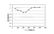
- FIG. 6 is a graph showing the relationship between the distance between the burner rows and the relative heat transfer efficiency in one embodiment of the present invention.
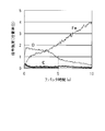
- FIG. 7 is an explanatory diagram relating to a method for evaluating the amount of carbon remaining on the surface of a degreasing test piece.
- the preheating chamber 3 is a portion that first receives the steel plate 2 in the heating device 1, and is a preheating portion A that preheats the steel plate 2.
- the preheating chamber 3 is provided with a steel plate inlet 8 into which the steel plate 2 is introduced on the upstream side in the moving direction X of the steel plate 2 (hereinafter simply referred to as “upstream side”). (Hereinafter simply referred to as “downstream side”) is connected to the heating chamber 4.
- the furnace length (length in the X direction) of the preheating chamber 3 is preferably designed in the range of 0.5 to 4 m, more preferably in the range of 1 to 4 m.
- the heating chamber 4 is a heating section B that heats the steel plate 2 to a desired temperature, the upstream side is connected to the preheating chamber 3, and the steel plate outlet 9 for taking out the steel plate is provided on the downstream side. .
- the furnace length (length in the X direction) of the heating chamber 4 is preferably in the range of the sum of the intervals L of the burner row E, which will be described later, +0.5 to 1.5 m. When the length is longer than 1.5 m, the heating chamber 4 becomes large, causing furnace heat loss. When the length is shorter than 0.5 m, the load on the combustion chamber of the heating unit is lowered, and the heat transfer efficiency is lowered. is there.
- the heating chamber 4 is provided with a plurality of burners 5 so as to sandwich the steel plate 2 from above and below.
- the burner 5 forms a flame D with fuel and an oxidant having an oxygen concentration of 80 vol% or more, more preferably 90 vol% or more.
- the burner 5 is arrange
- FIG. 2 is a perspective view in which the outer wall of the heating chamber 4 is omitted
- FIG. 3 is a cross-sectional view showing only the steel plate 2 and the burner 5.
- the distance H from the tip 5a of the burner 5 to the steel plate 2 is (30 to 110) ⁇ Q (1 / when the amount of combustion per burner 5 is Q [Mcal / h]. 3) It is preferably in the range of mm, and more preferably in the range of (60 to 110) ⁇ Q (1/3) mm. For example, if the combustion amount is 35 Mcal / h, the distance H is more preferably in the range of approximately 200 to 360 mm. If it is shorter than 30 ⁇ Q (1/3) mm, the possibility of damaging the burner 5 due to the rebound of the flame D increases. If it is longer than 110 ⁇ Q (1/3) mm, the flame D collides with the steel plate 2.
- the distance H from the tip 5a of the burner 5 to the steel plate 2 refers to the distance from the tip 5a of the burner 5 to the intersection P between the center axis M of the burner and the surface 2a of the steel plate 2, as shown in FIG.
- column E is formed of the several burner 5 provided in the direction perpendicular
- FIG. 4 is a plan view showing only the burner 5 and the steel plate 2.
- the interval d between the burners 5 constituting each burner row E is preferably in the range of (5 to 25) ⁇ Q (1/2) mm, and is in the range of (7 to 20) ⁇ Q (1/2) mm. More preferably. For example, when the combustion amount is 35 Mcal / h, it is more preferable that the distance d is in the range of approximately 40 to 120 mm.
- the interval d of the burners 5 is shorter than 5 ⁇ Q (1/2) mm, when heating the wide steel plate 2 or the like, it is necessary to provide a very large number of burners 5, which is not practical.
- interval d of the burner 5 is longer than 25 * Q (1/2) mm, it becomes difficult to heat the steel plate 2 uniformly.
- the burner row E is preferably arranged in two or more rows when the desired temperature of the steel plate 2 is high.
- the interval L between the burner rows E is preferably in the range of (17 to 300) ⁇ Q (1/2) mm, and is in the range of (17 to 68) ⁇ Q (1/2) mm, or ( More preferably, it is in the range of 100 to 300) ⁇ Q (1/2) mm.
- the interval L is more preferably set to a range of approximately 100 to 400 mm or 600 to 1800 mm.
- the interval L of the burner row E is shorter than 17 ⁇ Q (1/2) mm, the local combustion amount increases, and the possibility of damaging the burner 5 and the heating chamber 4 increases.
- the interval L between the burner rows E is longer than 68 ⁇ Q (1/2) mm and shorter than 100 ⁇ Q (1/2) mm, it is formed by the burners 5 in the rear row (burner row E 2 in FIG. 4).
- the flame D interferes with the flame D formed by the burners 5 in the front row (burner row E 1 in FIG. 4), and the flame D is peeled off from the surface 2a of the steel plate 2 to reduce the heat transfer efficiency.
- the interval L between the burner rows E is longer than 300 ⁇ Q (1/2) mm, the heating chamber 4 becomes large and the furnace body heat loss increases, which is not practical.
- the amount of combustion per burner 5 is preferably in the range of 10 to 100 Mcal / h, and more preferably in the range of 20 to 80 Mcal / h.
- the combustion amount is smaller than 10 Mcal / h, the flame length is shortened, so that the flame temperature when colliding with the steel sheet 2 is lowered and the flow velocity is also lowered, so that the heat transfer efficiency is lowered.
- it is higher than 100 Mcal / h, it is necessary to increase the distance between the burner 5 and the steel plate 2, the heating chamber 4 becomes larger, the furnace heat loss increases, and the thermal efficiency decreases.
- the steel plate 2 since the steel plate 2 is preheated in the preheating chamber 3 using the exhaust gas C containing the combustion gas of the burner 5, the steel plate 2 can be efficiently heated. Moreover, in this embodiment, since the oxidizing agent supplied to the burner 5 is an oxidizing agent having an oxygen concentration of 80 vol% or more, the fuel is burned rapidly, and a high-temperature high-speed flame can be formed. Since the flame D is directly collided with the steel plate 2, the steel plate 2 can be efficiently and rapidly heated.
- the method for heating a steel product (steel plate) according to this embodiment includes a preheating step of heating the steel plate 2 in the preheating chamber 3 and a heating step of heating the steel plate 2 in the heating chamber 4 connected to the preheating chamber 3. is doing.
- a steel plate 2 which is a steel product formed by cold rolling is put into the preheating chamber 3 from the steel plate inlet 8 and the steel plate 2 is moved to the heating chamber 4 side. And sequentially move along the X direction.
- the exhaust gas C containing the combustion gas of the burner 5 is introduced from the heating chamber 3 by the exhaust gas discharge means 7, and the steel plate 2 is preheated by exchanging heat between the exhaust gas C and the steel plate 2.
- the exhaust gas C heat-exchanged with the steel plate 2 is discharged out of the heating device 1 through the exhaust gas discharge pipe 6 by the exhaust gas discharge means 7.
- the steel plate 2 moves into the heating chamber 4, and a heating process is performed in the heating chamber 4.
- the steel plate 2 is heated to a desired temperature so that the flame D formed by the burner 5 formed in the heating chamber 4 directly collides with the surface 2a of the steel plate 2.
- the burner 5 is supplied with fuel and an oxidant having an oxygen concentration of 80 vol% or more, so the flame formed by the burner is a high-temperature high-speed flame.
- the steel plate 2 is rapidly and uniformly heated to a desired temperature, and the oil and fat adhered to the surface 2a of the steel plate 2 by the flame D of the burner 5, as well as inorganic particles and organic particles mixed in the oil and fat are removed. Blow away and remove while burning.
- the steel plate 2 that has undergone the heating process is taken out of the heating device 1 through the steel plate outlet 9.
- the steel plate 2 since the steel plate 2 is preheated in the preheating chamber 3 using the exhaust gas C containing the combustion gas of the burner 5, the steel plate 2 can be efficiently heated. Moreover, in this embodiment, since the oxidizing agent supplied to the burner 5 is an oxidizing agent having an oxygen concentration of 80 vol% or more, the fuel is burned rapidly, and a high-temperature high-speed flame can be formed. Since this flame is directly collided with the steel plate, the steel plate 2 can be efficiently and rapidly heated.
- a heating test of a cold-rolled steel sheet was performed using the heating apparatus shown in FIGS.
- LNG flow rate: 3.4 Nm 3 / h ⁇ book
- pure oxygen flow rate: 8.5 Nm 3 / h ⁇ book
- the combustion amount of one burner is 35 Mcal / h.
- the supply amount of the oxidant corresponds to 110% of the oxygen flow rate necessary for complete combustion of LNG.
- the number of burners was 41 on each of the upper and lower sides of the steel sheet, for a total of 82.
- the upper burner and the lower burner of the steel plate were alternately arranged in two rows, respectively (21 in the front row and 20 in the rear row).
- the interval between the burners was 60 mm, and the interval between the burner rows was 200 mm.
- the distance from the burner to the steel plate was 200 mm, and the angle formed by the central axis of the burner and the surface of the steel plate was set to 80 degrees in the direction in which the flame ejection direction of the burner and the moving direction of the steel plate face each other.
- the cold rolled steel sheet had a thickness of 0.4 mm, a width of 1250 mm, and a moving speed of 200 m / min.
- the temperature of the steel plate at the steel plate inlet of the heating device was 25 ° C.
- the steel plate throughput was 47 T / hour
- the heating time in the heating chamber was 0.3 seconds.
- the steel plate temperature was measured by using a radiation thermometer to measure the temperature distribution in the width direction of the steel plate having a plate width of 1250 mm (direction perpendicular to the moving direction X of the steel plate).
- the average temperature is a value obtained by averaging the temperature distribution in the width direction of the steel sheet.
- Example 2 a heating test of a cold-rolled steel sheet was performed by changing the burner interval using the heating apparatus shown in FIG.
- Table 1 shows the conditions of combustion and oxygen supply to the burner of the steel sheet heating device and the number of burners. The combustion amount of all burners is set to be approximately equal. Other conditions were the same as in Example 1.
- FIG. 5 shows the temperature deviation of the steel plate temperature at each point in the width direction of the steel plate with respect to the burner interval. From the results of this example, it can be seen that when the burner interval is widened, the temperature deviation in the width direction of the steel sheet increases and uniform heating is difficult. This result shows that about 60 mm is appropriate.
- Example 1 Under the conditions of Example 1, the distance between the burner rows was changed and the influence on the steel plate heat transfer efficiency was confirmed. Conditions other than the burner row interval were the same as those in Example 1.
- FIG. 6 shows the influence on the heat transfer efficiency with respect to the burner row interval.
- the heat transfer efficiency is shown as a relative heat transfer efficiency with a heat transfer efficiency of 1.0 at a burner row interval of 300 mm.
- the relative heat transfer efficiency tends to become a minimum value when the burner row interval is 400 to 500 mm, and therefore it is preferable that the burner interval is 100 to 300 mm, or 600 mm or more.
- LNG was used as the fuel supplied to the burner disposed in the heating chamber, and pure oxygen was used as the oxidant.
- the fuel and oxidant supplied to one burner are LNG as the fuel: flow rate 3.4 Nm 3 / h
- the pure oxygen as the oxidizer was 8.5 Nm 3 / h.
- the flow rate of the pure oxygen was set to 110% of the amount necessary for complete combustion of the fuel.
- the burners were arranged in the same manner as in FIG. 4, that is, five in the front row E1 and six in the rear row E2.
- the burner height H is 200 mm
- the burner angle ⁇ is 70 °
- the burner interval d and the burner row interval L are determined as Test No. Different settings were used. However, the burner was installed only on the upper side of the steel plate.
- a cold rolled steel plate having a plate width of 600 mm and a plate thickness of 0.6 mm was prepared.
- the burner is burned at various combustion load factors, and the prepared cold rolled steel sheet is run in the X direction in FIG. 1 at various moving speeds, and the flame of the burner is directly collided with the surface of the cold rolled steel sheet.
- the oils and fats adhering to were burned and removed.
- Table 2 shows the burner combustion conditions and the moving speed of the cold-rolled steel sheet.
- the burnability of oils and fats was evaluated as follows. From each cold-rolled steel sheet after the degreasing test, 7 to 13 samples were collected from the center of the sheet width to prepare a degreasing test piece. The number and position of the collected samples are as shown in Table 3 according to the burner interval d.
- the element distribution analysis of the depth direction by argon ion sputtering was performed from the surface of the cold-rolled steel plate using the glow discharge luminescence surface analyzer (GDS).
- GDS glow discharge luminescence surface analyzer
- the carbon content of each of the degreasing test specimens collected from 7 to 13 locations in the plate width direction was averaged, and this was regarded as the residual carbon content, and the combustion removal property of the fats and oils was evaluated based on the magnitude.
- the evaluation results are shown in Table 4.
- the comparative material of Table 4 is the result of having obtained the amount of residual carbon using the degreasing test piece extract
- the residual carbon content of the comparative material is 0.3, while test No.
- the amount of residual carbon of 1 to 15 was 0.3 to 0.5, and at most 0.7. In other words, the amount of carbon remaining in the comparative material could be reduced to almost the same level. From this, it has been confirmed that the oil and fat adhering to the surface of the steel product can be burned and removed to the extent equivalent to alkaline degreasing using the heating method of the present invention. It was also confirmed that the oils and fats adhering to the surface of the steel product could be burned and removed even under various burner spacing d, burner row spacing L, combustion load factor, and steel plate moving speed.
Landscapes
- Engineering & Computer Science (AREA)
- Mechanical Engineering (AREA)
- Chemical & Material Sciences (AREA)
- General Engineering & Computer Science (AREA)
- Environmental & Geological Engineering (AREA)
- Crystallography & Structural Chemistry (AREA)
- Thermal Sciences (AREA)
- Materials Engineering (AREA)
- Metallurgy (AREA)
- Organic Chemistry (AREA)
- Physics & Mathematics (AREA)
- Combustion & Propulsion (AREA)
- Heat Treatment Of Strip Materials And Filament Materials (AREA)
- Tunnel Furnaces (AREA)
Abstract
Description
本願は、2015年3月26日に、日本に出願された特願2015-065015号に基づき優先権を主張し、その内容をここに援用する。
もっとも、火炎からのふく射熱によって間接的に加熱するので、炉体を大きくする必要があり、熱効率が悪かった。
また、燃焼速度が遅いため、火炎の吹き飛びの問題から、高速の火炎を形成しにくかった。そのため、火炎を衝突させるタイプの加熱装置であっても、鉄鋼製品を急速に加熱するには限界があった。
(1)冷間圧延にて成形した鉄鋼製品の加熱装置であって、前記鉄鋼製品を予熱するための予熱室と、前記予熱室に連結され、前記鉄鋼製品を所望の温度まで加熱するための加熱室と、前記加熱室において前記鉄鋼製品を上下から挟みこむように配置された複数本のバーナと、前記バーナでの燃焼ガスを含む排ガスを、前記予熱室内に流入した後に前記加熱装置外に排出する排ガス排出手段と、を備え、前記バーナは、燃料と酸素濃度が80vol%以上の酸化剤とによって火炎を形成し、前記火炎によって前記鉄鋼製品の表面に付着した油脂、並びに前記油脂に混入した無機物粒子及び有機物粒子の少なくとも1つを燃焼させつつ吹き払う機能を有し、前記予熱室は、前記排ガス排出手段によって流入した前記バーナでの燃焼ガスを含む排ガスによって、前記鉄鋼製品の予熱を行う構造となっている鉄鋼製品の加熱装置。
まず、本実施形態の鉄鋼製品の加熱装置について説明する。
本実施形態の鉄鋼製品(鋼板)の加熱装置1は、図1に示すように、冷間圧延にて成形した鉄鋼製品である鋼板2を加熱する装置であり、鋼板2を予熱する予熱室3と、予熱室3に連結された加熱室4と、加熱室4内に設けられた複数本のバーナ5と、予熱室3に接続された排ガス排出管6と、排ガス排出管6に設けられた排ガス排出手段7と、を備えた構成となっている。
図1は、本実施形態の加熱装置1の概略構成を示した断面図である。また、図1ないし図4において、矢印Xは、鋼板2の移動方向を示している。
予熱室3の炉長(X方向の長さ)は、0.5~4mの範囲に設計されているのが好ましく、1~4mの範囲に設計されているのがより好ましい。4mよりも長くしても鋼板の加熱効率はほとんど変わらず、無駄に設備が大きくなり設備コストが高くなるという不都合があり、0.5mよりも短いと、加熱装置1の排ガスの熱量を回収できないこととなり、排ガスの熱損が多くなるという不都合がある。
このように、予熱室3は、排ガス排出手段7によって、加熱室4から流入したバーナ5での燃焼ガスを含む排ガスCと、鋼板2を熱交換することで、鋼板2の予熱を行う構造となっている。
この加熱室4の炉長(X方向の長さ)は、後述するバーナ列Eの間隔Lの総和+0.5~1.5mの範囲であるのが好ましい。1.5mよりも長いと、加熱室4が大きくなり、炉体熱損が生じ、また、0.5mよりも短いと、加熱部の燃焼室負荷が低下し、伝熱効率が低下するという不都合がある。
バーナ5は、燃料と酸素濃度が80vol%以上、より好ましくは90vol%以上の酸化剤とによって火炎Dを形成する。そして、バーナ5は、図2及び図3に示すように、火炎Dが直接鋼板2の表面2aに衝突するような位置に配置されている。
図2は、加熱室4の外壁を省略した斜視図であり、図3は鋼板2とバーナ5のみを記した断面図である。
30×Q(1/3)mmより短いと、火炎Dの跳ね返りによりバーナ5を損傷させる可能性が大きくなり、110×Q(1/3)mmよりも長いと、火炎Dが鋼板2に衝突する際の流速及び温度が低下してしまい、高い伝熱効率を得ることができない。
バーナ5の先端5aから鋼板2までの距離Hとは、図3に示すように、バーナ5の先端5aからバーナの中心軸Mと鋼板2の表面2aとの交点Pまでの距離を言う。
角度αが60度よりも小さい場合、伝熱効率が低下し、90度より大きい場合も同様に伝熱効果の低下が顕著となる。
また、各バーナ5によって、バーナ5の中心軸Mと鋼板2の表面2aとがなす角度αが異なっても構わないが、鋼板2を均一に加熱するためには、全てのバーナ5が同じ角度で設けられているのが好ましい。
図4は、バーナ5と鋼板2のみを示した平面図である。
バーナ5の間隔dが5×Q(1/2)mmよりも短い場合、幅の広い鋼板2などを加熱する場合、非常に多数のバーナ5を設ける必要があり、実用的ではない。また、バーナ5の間隔dが25×Q(1/2)mmより長い場合、鋼板2を均一に加熱することが困難となる。
バーナ列Eの間隔Lが17×Q(1/2)mmより短い場合、局所的な燃焼量が大きくなり、バーナ5及び加熱室4を損傷する可能性が大きくなる。また、バーナ列Eの間隔Lが、68×Q(1/2)mmより長く100×Q(1/2)mmより短い場合、後列(図4におけるバーナ列E2)のバーナ5によって形成される火炎Dが前列(図4におけるバーナ列E1)のバーナ5によって形成される火炎Dと干渉することになり、火炎Dが鋼板2の表面2aから剥離した状態となり、伝熱効率が低下する。また、バーナ列Eの間隔Lを300×Q(1/2)mmより長くした場合、加熱室4が大きくなり、炉体熱損が増加するため実用的ではない。
また、バーナ5の1本あたりの燃焼量は、10~100Mcal/hの範囲にあることが好ましく、20~80Mcal/hの範囲にあることがより好ましい。燃焼量が10Mcal/hより小さい場合、火炎長が短くなるため、鋼板2に衝突する際の火炎温度が低くなるとともに、流速も低下するため、伝熱効率が低下する。また、100Mcal/hより大きくすると、バーナ5と鋼板2の距離を大きくする必要があり、加熱室4が大きくなり、炉体熱損が増加し、熱効率が低下する。
また、本実施形態では、バーナ5に供給する酸化剤として、酸素濃度80vol%以上の酸化剤を用いているので、燃料を急速に燃焼させることとなり、高温高速火炎を形成することができる。この火炎Dを直接鋼板2に衝突させているので、鋼板2を効率よく急速に加熱することができる。また、高温高速火炎を衝突させることで、鋼板2の表面2aに付着した油脂、並びに油脂に混入した有機物粒子及び無機物粒子を燃焼させつつ、この高温高速火炎によって吹き払うことが可能となる。
次に、本実施形態の鉄鋼製品の加熱方法について説明する。
本実施形態の鉄鋼製品(鋼板)の加熱方法は、鋼板2を予熱室3にて加熱する予熱工程と、鋼板2を予熱室3に連結された加熱室4で加熱する加熱工程と、を有している。
予熱室3内には、排ガス排出手段7によって、加熱室3から、バーナ5の燃焼ガスを含む排ガスCが導入されており、この排ガスCと鋼板2を熱交換することで、鋼板2を予熱する。
この加熱工程では、加熱室4内に形成されたバーナ5によって形成された火炎Dが、直接、鋼板2の表面2aに衝突するようにして、鋼板2を所望の温度まで加熱する。この際、バーナ5には燃料と酸素濃度が80vol%以上の酸化剤が供給されているので、バーナが形成する火炎は、高温高速火炎となっている。
また、バーナ5に供給する酸化剤に含まれる酸素流量が、バーナに供給する燃料を完全燃焼させるのに必要な酸素流量の90~120%の範囲となるように、酸化剤及び燃料の流量を適宜調整するのが好ましい。
バーナ5に供給する酸化剤に含まれる酸素流量が、燃料を完全に燃焼させるのに必要な酸素流量の90%よりも少ない場合は、未燃ガスが排出され排ガス熱損が多くなるといった不都合があり、120%よりも多い場合は、鋼板の酸化量が多くなるといった不都合がある。
加熱工程を経た鋼板2は、鋼板取出口9を通って加熱装置1外へと取り出される。
また、本実施形態では、バーナ5に供給する酸化剤として、酸素濃度80vol%以上の酸化剤を用いているので、燃料を急速に燃焼させることとなり、高温高速火炎を形成することができる。この火炎を直接鋼板に衝突させているので、鋼板2を効率よく急速に加熱することができる。また、高温高速火炎を衝突させることで、鋼板2の表面2aに付着した油脂、並びに油脂に混入した有機物粒子及び無機物粒子を燃焼させつつ、この高温高速火炎によって吹き払うことが可能となる。
加熱室に配置したバーナへ供給する燃料としてはLNG(流量:3.4Nm3/h・本)を用い、酸化剤としては純酸素(流量:8.5Nm3/h・本)を用いた。したがって、バーナ1本の燃焼量は35Mcal/hとなる。また、酸化剤の供給量は、LNGを完全燃焼するのに必要な酸素流量の110%に相当する。
バーナの本数は、鋼板の上側及び下側ともに41本ずつ、合計82本とした。また、鋼板の上側のバーナ及び下側のバーナは、ともに2列にそれぞれ互い違いに配置した(前列21本、後列20本)。各バーナの間隔は60mmとし、バーナ列の間隔は200mmとした。
また、バーナから鋼板までの距離は200mmとし、バーナの中心軸と鋼板の表面との成す角度を、バーナの火炎の噴出方向と鋼板の移動方向が対向する向きで80度となるようにした。
また、冷間圧延鋼板は、板厚0.4mm、板幅1250mm、移動速度200m/minとした。加熱装置の鋼板入口での鋼板の温度を25℃とし、鋼板処理量を47T/hourとし、加熱室での加熱時間を0.3秒とした。
鋼板温度は、放射温度計を用いて、板幅1250mmの範囲の鋼板の幅方向(鋼板の移動方向Xに対して垂直の方向)の温度分布を測定した。平均温度は、鋼板の幅方向の温度分布を平均した値である。
鋼板加熱装置のバーナへの燃焼と酸素の供給条件およびバーナ本数を表1に示す。全バーナの燃焼量が概ね等しくなるようにしている。その他の条件は、実施例1と同じとした。

バーナ列間隔以外の条件は、実施例1と同じ条件とした。図6にバーナ列間隔に対する伝熱効率への影響を示す。伝熱効率は、バーナ列間隔300mmの条件の伝熱効率を1.0とした相対伝熱効率で示す。
・本、酸化剤として純酸素:8.5Nm3/h・本とし、純酸素の流量は燃料を完全燃焼
させるために必要な量の110%となるように設定した。
バーナは、図4と同様に、すなわち前列E1として5本、後列E2として6本の計11本を配置した。また、バーナ高さHは200mm、バーナ角度αは70°とし、バーナ間隔dとバーナ列間隔Lは、試験No.ごとに異なる設定とした。ただし、バーナは鋼板の上側のみに設置した。
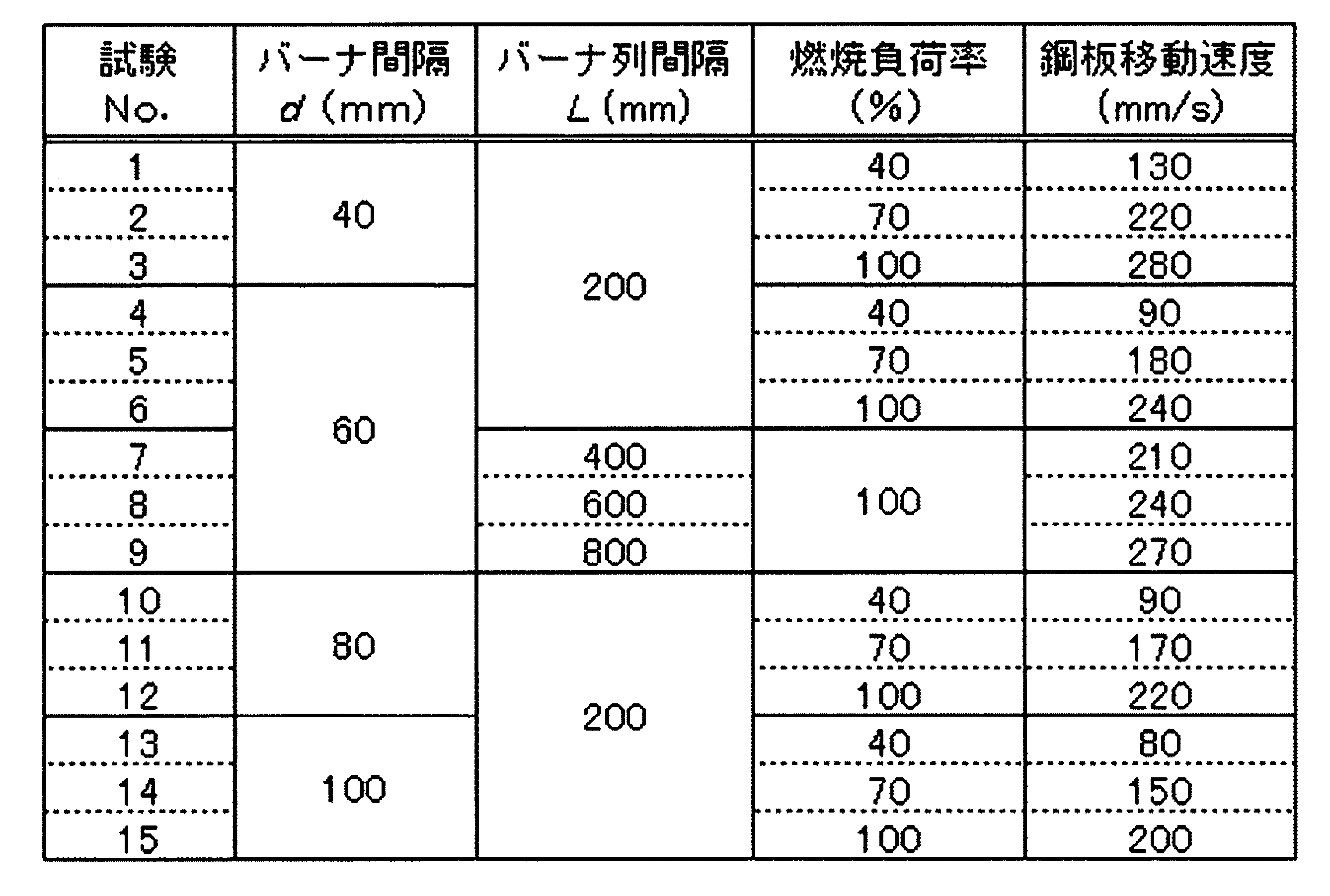
脱脂試験を終えたそれぞれの冷間圧延鋼板から、板幅中央を中心に7ないし13箇所のサンプルを採取して脱脂試験片を準備した。採取したサンプルの個数と位置はバーナ間隔dに応じて、表3のとおりとした。

表4の比較材は、冷間圧延鋼板をアセトンにより脱脂し、7箇所から採取した脱脂試験片を用いて残留カーボン量を求めた結果である。
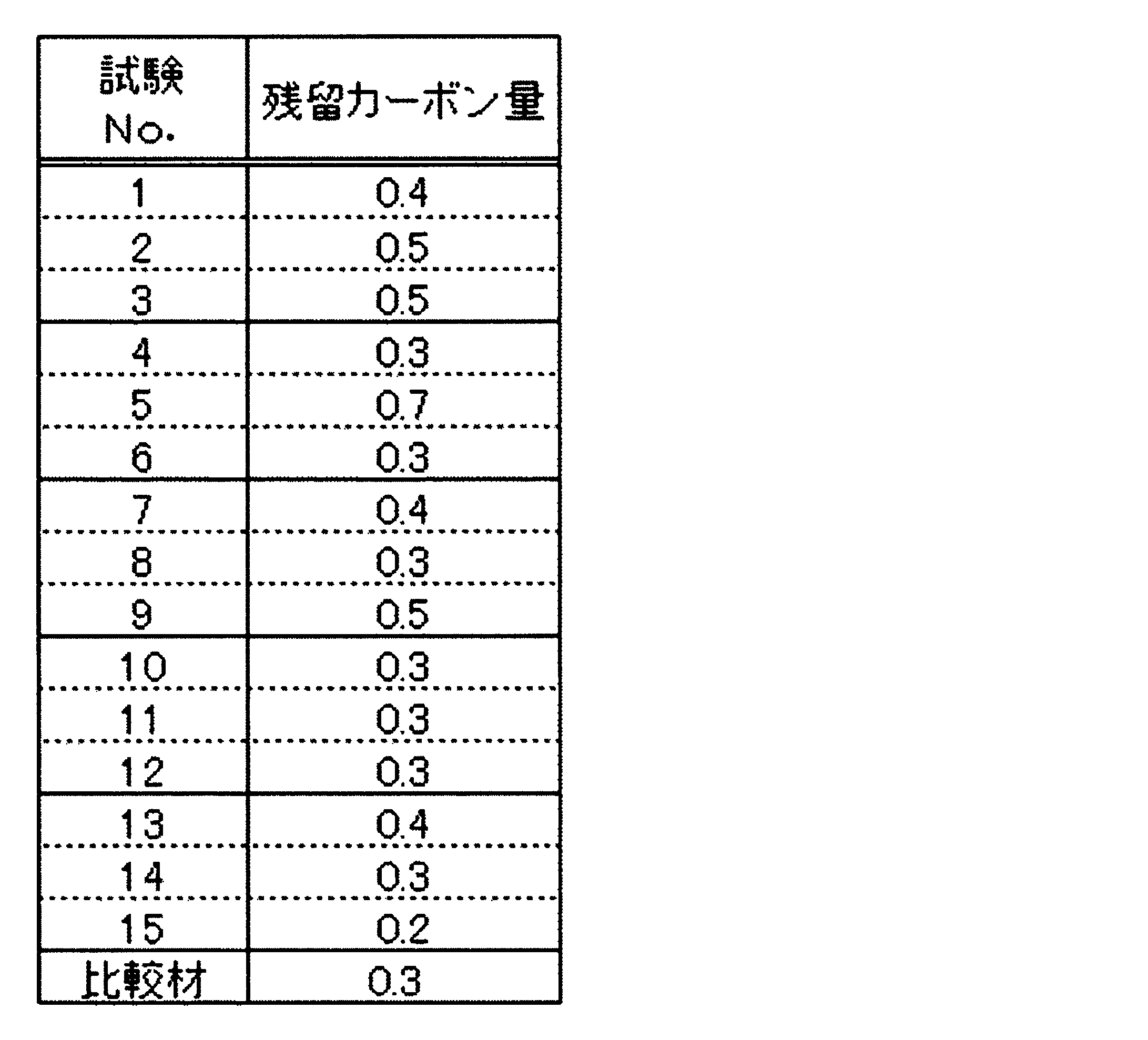
その結果、脱脂試験片No.1~15について、鋼板表面の酸化膜の厚みはすべて0.1μm程度で、比較材と同等であった。
2 鋼板
2a 鋼板の表面
3 予熱室
4 加熱室
5 バーナ
6 排ガス排出管
7 排ガス排出手段
8 鋼板入口
9 鋼板取出口
A 予熱部
B 加熱部
C 排ガス
D 火炎
E バーナ列
Claims (13)
- 冷間圧延にて成形した鉄鋼製品の加熱装置であって、
前記鉄鋼製品を予熱するための予熱室と、
前記予熱室に連結され、前記鉄鋼製品を所望の温度まで加熱するための加熱室と、
前記加熱室において前記鉄鋼製品を上下から挟みこむように配置された複数本のバーナと、
前記バーナでの燃焼ガスを含む排ガスを、前記予熱室内に流入した後に前記加熱装置外に排出する排ガス排出手段と、を備え、
前記バーナは、燃料と酸素濃度が80vol%以上の酸化剤とによって火炎を形成し、前記火炎によって前記鉄鋼製品の表面に付着した油脂、並びに前記油脂に混入した無機物粒子及び有機物粒子の少なくとも1つを燃焼させつつ吹き払う機能を有し、
前記予熱室は、前記排ガス排出手段によって流入した前記バーナでの燃焼ガスを含む排ガスによって、前記鉄鋼製品の予熱を行う構造となっている鉄鋼製品の加熱装置。 - 前記バーナの1本あたりの燃焼量をQ[Mcal/h]とした場合に、前記バーナの先端と前記鉄鋼製品との間の距離Hを(30~110)×Q(1/3)mmの範囲とし、前記バーナの中心軸と前記鉄鋼製品との表面とが成す角度αを60~90度の範囲とする請求項1に記載の鉄鋼製品の加熱装置。
- 前記鉄鋼製品の上側の前記バーナ又は/及び前記鉄鋼製品の下側の前記バーナが、1列に複数配置されており、
前記バーナの1本あたりの燃焼量をQ[Mcal/h]とした場合に、前記1列に配置された複数の前記バーナの間隔dを(7~20)×Q(1/2)mmの範囲とする請求項1又は請求項2に記載の鉄鋼製品の加熱装置。 - 前記鉄鋼製品の上側の前記バーナ又は/及び前記鉄鋼製品の下側の前記バーナが、2列以上のバーナ列を形成するように配置されており、
前記バーナの1本あたりの燃焼量をQ[Mcal/h]とした場合に、前記バーナ列の間隔Lを(17~300)×Q(1/2)mmの範囲とする請求項1ないし請求項3のいずれか1項に記載の鉄鋼製品の加熱装置。 - 前記バーナ列の前記間隔Lを(17~68)×Q(1/2)mmの範囲、又は(100~300)×Q(1/2)mmの範囲とする請求項4に記載の鉄鋼製品の加熱装置。
- 2列以上のバーナ列を形成するように配置された前記バーナが、それぞれ互い違いに配置されている請求項4又は請求項5に記載の鉄鋼製品の加熱装置。
- 冷間圧延にて成形した鉄鋼製品の加熱方法であって、
前記鉄鋼製品を予熱室にて加熱した後に、前記予熱室に連結された加熱室に導入して所望の温度まで加熱する方法であり、
前記加熱室には、前記鉄鋼製品を上下から挟みこむように配置された複数本のバーナが設けられており、
燃料と酸素濃度が80vol%以上の酸化剤とを用いて前記バーナによって形成した火炎を、前記鉄鋼製品の表面に直接衝突させることによって、前記鉄鋼製品を加熱するとともに、前記鉄鋼製品の表面に付着した油脂、並びに前記油脂に混入した無機物粒子及び有機物粒子の少なくとも1つを燃焼させつつ前記火炎によって吹き払い、
前記バーナでの燃焼ガスを含む排ガスを前記予熱室に導入することで、前記鉄鋼製品と熱交換させる鉄鋼製品の加熱方法。 - 前記バーナに供給する前記酸化剤の流量を、前記燃料を完全燃焼させるのに必要な酸素流量の90~120%の範囲とする請求項7に記載の鉄鋼製品の加熱方法。
- 前記バーナの1本あたりの燃焼量をQ[Mcal/h]とした場合に、前記バーナの先端と前記鉄鋼製品との間の距離Hを(30~100)×Q(1/3)mmの範囲とし、前記バーナの中心軸と前記鉄鋼製品との表面とが成す角度αを60~90度の範囲とする請求項7又は請求項8に記載の鉄鋼製品の加熱方法。
- 前記鉄鋼製品の上側の前記バーナ又は/及び前記鉄鋼製品の下側の前記バーナが、1列に複数配置されており、
前記バーナの1本あたりの燃焼量をQ[Mcal/h]とした場合に、前記1列に配置された複数の前記バーナの間隔dを(7~20)×Q(1/2)mmの範囲とする請求項7ないし請求項9のいずれか1項に記載の鉄鋼製品の加熱方法。 - 前記鉄鋼製品の上側の前記バーナ又は/及び前記鉄鋼製品の下側の前記バーナが、2列以上のバーナ列を形成するように配置されており、
前記バーナの1本あたりの燃焼量をQ[Mcal/h]とした場合に、前記バーナ列の間隔Lを(17~300)×Q(1/2)mmの範囲とする請求項7ないし請求項10のいずれか1項に記載の鉄鋼製品の加熱方法。 - 前記バーナ列の前記間隔Lを(17~68)×Q(1/2)mmの範囲、又は(100~300)×Q(1/2)mmの範囲とする請求項11に記載の鉄鋼製品の加熱方法。
- 前記バーナの1本あたりの燃焼量を10~100Mcal/hの範囲とする請求項7ないし請求項12のいずれか1項に記載の鉄鋼製品の加熱方法。
Priority Applications (5)
| Application Number | Priority Date | Filing Date | Title |
|---|---|---|---|
| CN201680017436.9A CN107429972B (zh) | 2015-03-26 | 2016-03-25 | 钢铁产品的加热装置及钢铁产品的加热方法 |
| JP2017508472A JPWO2016153049A1 (ja) | 2015-03-26 | 2016-03-25 | 鉄鋼製品の加熱装置及び鉄鋼製品の加熱方法 |
| KR1020177027022A KR102040517B1 (ko) | 2015-03-26 | 2016-03-25 | 철강 제품의 가열 장치 및 철강 제품의 가열 방법 |
| MYPI2017703330A MY182961A (en) | 2015-03-26 | 2016-03-25 | Device for heating iron and steel products, and method for heating iron and steel products |
| US15/557,586 US20180044758A1 (en) | 2015-03-26 | 2016-03-25 | Device for heating iron and steel products, and method for heating iron and steel products |
Applications Claiming Priority (2)
| Application Number | Priority Date | Filing Date | Title |
|---|---|---|---|
| JP2015-065015 | 2015-03-26 | ||
| JP2015065015 | 2015-03-26 |
Publications (1)
| Publication Number | Publication Date |
|---|---|
| WO2016153049A1 true WO2016153049A1 (ja) | 2016-09-29 |
Family
ID=56977851
Family Applications (1)
| Application Number | Title | Priority Date | Filing Date |
|---|---|---|---|
| PCT/JP2016/059695 Ceased WO2016153049A1 (ja) | 2015-03-26 | 2016-03-25 | 鉄鋼製品の加熱装置及び鉄鋼製品の加熱方法 |
Country Status (7)
| Country | Link |
|---|---|
| US (1) | US20180044758A1 (ja) |
| JP (1) | JPWO2016153049A1 (ja) |
| KR (1) | KR102040517B1 (ja) |
| CN (1) | CN107429972B (ja) |
| MY (1) | MY182961A (ja) |
| TW (1) | TWI685570B (ja) |
| WO (1) | WO2016153049A1 (ja) |
Families Citing this family (2)
| Publication number | Priority date | Publication date | Assignee | Title |
|---|---|---|---|---|
| CN111668632B (zh) * | 2020-05-14 | 2025-03-28 | 江西巴斯巴新能源技术有限公司 | 一种大电流线簧接触片模块结构及大电流端子连接结构 |
| WO2023229806A1 (en) * | 2022-05-24 | 2023-11-30 | Corning Incorporated | Apparatuses and methods for processing optical fiber |
Citations (4)
| Publication number | Priority date | Publication date | Assignee | Title |
|---|---|---|---|---|
| JPS5330930A (en) * | 1976-09-03 | 1978-03-23 | Nippon Steel Corp | Direct heat type nonnoxidizing heat treatment method of continuous molten zinc plating apparatus |
| JPS5597422A (en) * | 1979-01-20 | 1980-07-24 | Nippon Steel Corp | Fast heating appartaus for continuous annealing installation |
| JPS5613440A (en) * | 1979-07-09 | 1981-02-09 | Daido Steel Co Ltd | Continuous heating furnace with preheating throat |
| JP2009525401A (ja) * | 2006-02-03 | 2009-07-09 | リンデ アクチエンゲゼルシヤフト | 酸素−燃料バーナーを備えた連続熱処理炉内における鋼帯の熱処理方法 |
Family Cites Families (8)
| Publication number | Priority date | Publication date | Assignee | Title |
|---|---|---|---|---|
| JPS57104632A (en) * | 1980-12-19 | 1982-06-29 | Ishikawajima Harima Heavy Ind Co Ltd | Heater for continuous type heat treatment furnace |
| CN1011982B (zh) * | 1985-07-10 | 1991-03-13 | 日本钢管株式会社 | 具有明火加热炉的带钢连续处理作业线 |
| JPS6254031A (ja) * | 1985-08-31 | 1987-03-09 | Nippon Kokan Kk <Nkk> | 鋼帯の連続焼鈍設備における直火加熱炉 |
| JPH0537954U (ja) | 1991-10-29 | 1993-05-21 | 三菱重工業株式会社 | 直火式連続加熱炉における鋼帯の加熱装置 |
| JP3168753B2 (ja) * | 1993-01-07 | 2001-05-21 | 日本鋼管株式会社 | 金属帯連続処理ラインの直火還元加熱設備における通板方法 |
| JP3937729B2 (ja) * | 2001-01-17 | 2007-06-27 | Jfeスチール株式会社 | 加熱炉の雰囲気制御方法および加熱炉 |
| JP2006284019A (ja) | 2005-03-31 | 2006-10-19 | Jfe Steel Kk | 直火式鋼板連続加熱炉および鋼板の加熱方法 |
| JP5597422B2 (ja) * | 2010-01-19 | 2014-10-01 | デクセリアルズ株式会社 | 接着フィルム付き電子部品の製造方法および実装体の製造方法 |
-
2016
- 2016-03-25 JP JP2017508472A patent/JPWO2016153049A1/ja active Pending
- 2016-03-25 US US15/557,586 patent/US20180044758A1/en not_active Abandoned
- 2016-03-25 TW TW105109402A patent/TWI685570B/zh not_active IP Right Cessation
- 2016-03-25 KR KR1020177027022A patent/KR102040517B1/ko not_active Expired - Fee Related
- 2016-03-25 MY MYPI2017703330A patent/MY182961A/en unknown
- 2016-03-25 CN CN201680017436.9A patent/CN107429972B/zh not_active Expired - Fee Related
- 2016-03-25 WO PCT/JP2016/059695 patent/WO2016153049A1/ja not_active Ceased
Patent Citations (4)
| Publication number | Priority date | Publication date | Assignee | Title |
|---|---|---|---|---|
| JPS5330930A (en) * | 1976-09-03 | 1978-03-23 | Nippon Steel Corp | Direct heat type nonnoxidizing heat treatment method of continuous molten zinc plating apparatus |
| JPS5597422A (en) * | 1979-01-20 | 1980-07-24 | Nippon Steel Corp | Fast heating appartaus for continuous annealing installation |
| JPS5613440A (en) * | 1979-07-09 | 1981-02-09 | Daido Steel Co Ltd | Continuous heating furnace with preheating throat |
| JP2009525401A (ja) * | 2006-02-03 | 2009-07-09 | リンデ アクチエンゲゼルシヤフト | 酸素−燃料バーナーを備えた連続熱処理炉内における鋼帯の熱処理方法 |
Also Published As
| Publication number | Publication date |
|---|---|
| CN107429972A (zh) | 2017-12-01 |
| KR102040517B1 (ko) | 2019-11-07 |
| TW201702387A (zh) | 2017-01-16 |
| US20180044758A1 (en) | 2018-02-15 |
| MY182961A (en) | 2021-02-05 |
| KR20170120159A (ko) | 2017-10-30 |
| JPWO2016153049A1 (ja) | 2017-11-02 |
| TWI685570B (zh) | 2020-02-21 |
| CN107429972B (zh) | 2021-12-24 |
Similar Documents
| Publication | Publication Date | Title |
|---|---|---|
| CA1170042A (en) | Jet impingement/radiant heating apparatus | |
| CN100577825C (zh) | 直燃式金属管材光亮热处理炉 | |
| JP2009528444A (ja) | 金属熱処理方法及び装置 | |
| CN103290191A (zh) | 一种热处理炉余热回收装置 | |
| Xu et al. | Analysis of nozzle designs on zoned and staged double P-type gas-fired radiant tube | |
| JP5180291B2 (ja) | 希薄燃焼 | |
| WO2016153049A1 (ja) | 鉄鋼製品の加熱装置及び鉄鋼製品の加熱方法 | |
| CN102925833B (zh) | 一种采用连续热处理炉生产铍青铜带材的方法 | |
| CN100577826C (zh) | 直燃式金属管材光亮热处理方法 | |
| TWI697563B (zh) | 鋼胚加熱爐及抑制鋼胚表面脫碳層之厚度增加的方法 | |
| CN202830108U (zh) | 带钢连续退火中的蓄热式直烧炉 | |
| JP5268303B2 (ja) | 加熱炉の降温方法及び加熱炉 | |
| CN201186941Y (zh) | 直燃式金属管材光亮热处理炉 | |
| CN107923709A (zh) | 用于再加热金属产品的设备和方法 | |
| JP4112670B2 (ja) | 表面性状に優れた鋼板の製造方法 | |
| KR101328241B1 (ko) | 분위기 가열장치 | |
| JPH0230720A (ja) | 鋼板の加熱方法 | |
| RU2090810C1 (ru) | Печь для нагрева нефти | |
| CN208791706U (zh) | 一种铝卷退火炉 | |
| CN101435018A (zh) | 一种热镀锌退火工艺和高温退火炉 | |
| JP2733885B2 (ja) | 鋼帯の連続熱処理方法 | |
| Docquier et al. | 5.1 Metals Industry | |
| JPH0781167B2 (ja) | 鋼帯の直火式連続焼鈍方法及び装置 | |
| CN202582223U (zh) | 用于热处理炉的热能回收利用装置 | |
| Soroka | Reduction of Environmental Pollution under Natural Gas Combustion by Means of Flat-Flame Burners of New Generation |
Legal Events
| Date | Code | Title | Description |
|---|---|---|---|
| 121 | Ep: the epo has been informed by wipo that ep was designated in this application |
Ref document number: 16768952 Country of ref document: EP Kind code of ref document: A1 |
|
| ENP | Entry into the national phase |
Ref document number: 2017508472 Country of ref document: JP Kind code of ref document: A |
|
| WWE | Wipo information: entry into national phase |
Ref document number: 15557586 Country of ref document: US |
|
| ENP | Entry into the national phase |
Ref document number: 20177027022 Country of ref document: KR Kind code of ref document: A |
|
| NENP | Non-entry into the national phase |
Ref country code: DE |
|
| 122 | Ep: pct application non-entry in european phase |
Ref document number: 16768952 Country of ref document: EP Kind code of ref document: A1 |